Featuring Flexibility Manual addendum — Venting · GAS-FIRED WATER BOILER — Manual addendum —...
28
This addendum must only be used by a qualified heating installer/service technician. Read all instructions, including the Ultra boiler manual and all other information shipped with the boiler, before installing. Perform steps in the order given. Failure to comply could result in severe personal injury, death or substantial property damage. Manual addendum — Venting Gas-fired water boilers – Series 3 Featuring Flexibility Part number 550-100-103/1110 ® Contents Venting & air — general . . . . . . . . . . . . . . . . . . . . . . . . . . . . . . . . . . . . . . . . . . . . . . 2 Sidewall vent/air termination: 3” or 4” concentric . . . . . . . . . . . . . . . . . . . . . . . . . . . . . . . . . 8 Vertical vent/air termination: 3” or 4” concentric . . . . . . . . . . . . . . . . . . . . . . . . . . . . . . . . 11 Concentric vent/air termination assembly. . . . . . . . . . . . . . . . . . . . . . . . . . . . . . . . . . . . 14 DIRECT VENT: Vertical vent / sidewall air . . . . . . . . . . . . . . . . . . . . . . . . . . . . . . . . . . . 15 Install vent/air piping — boiler to termination . . . . . . . . . . . . . . . . . . . . . . . . . . . . . . . . . . 18 DIRECT EXHAUST venting — general . . . . . . . . . . . . . . . . . . . . . . . . . . . . . . . . . . . . . 19 DIRECT EXHAUST — Boiler room air openings . . . . . . . . . . . . . . . . . . . . . . . . . . . . . . . . 20 DIRECT EXHAUST — Sidewall . . . . . . . . . . . . . . . . . . . . . . . . . . . . . . . . . . . . . . . . 22 DIRECT EXHAUST — Vertical . . . . . . . . . . . . . . . . . . . . . . . . . . . . . . . . . . . . . . . . . 25 Supplementary instructions for: Additional concentric vent/air termination kits, including IPEX System 636 in 3-inch and 4-inch sizes (for information on IPEX, go to www.ipexinc.com) Direct exhaust venting (requires combustion air openings to boiler room/building per this addendum). Direct vent with Roof exhaust and Sidewall air intake
Transcript of Featuring Flexibility Manual addendum — Venting · GAS-FIRED WATER BOILER — Manual addendum —...

This addendum must only be used by a qualified heating installer/service technician. Read all instructions, including the Ultra boiler manual and all other information shipped with the boiler, before installing. Perform steps in the order given. Failure to comply could result in severe personal injury, death or substantial property damage.
Manual addendum — Venting
Gas-fired water boilers – Series 3
Featuring
Flexibility
Part number 550-100-103/1110
®
Contents
Venting & air — general. . . . . . . . . . . . . . . . . . . . . . . . . . . . . . . . . . . . . . . . . . . . . . 2
Sidewall vent/air termination: 3” or 4” concentric . . . . . . . . . . . . . . . . . . . . . . . . . . . . . . . . . 8
Vertical vent/air termination: 3” or 4” concentric . . . . . . . . . . . . . . . . . . . . . . . . . . . . . . . . 11
Concentric vent/air termination assembly. . . . . . . . . . . . . . . . . . . . . . . . . . . . . . . . . . . . 14
DIRECT VENT: Vertical vent / sidewall air . . . . . . . . . . . . . . . . . . . . . . . . . . . . . . . . . . . 15
Install vent/air piping — boiler to termination . . . . . . . . . . . . . . . . . . . . . . . . . . . . . . . . . . 18
DIRECT EXHAUST venting — general . . . . . . . . . . . . . . . . . . . . . . . . . . . . . . . . . . . . . 19
DIRECT EXHAUST — Boiler room air openings . . . . . . . . . . . . . . . . . . . . . . . . . . . . . . . . 20
DIRECT EXHAUST — Sidewall . . . . . . . . . . . . . . . . . . . . . . . . . . . . . . . . . . . . . . . . 22
DIRECT EXHAUST — Vertical . . . . . . . . . . . . . . . . . . . . . . . . . . . . . . . . . . . . . . . . . 25
Supplementary instructions for:
Additional concentric vent/air termination kits, including IPEX System 636 in 3-inch and 4-inch sizes (for information on IPEX, go to www.ipexinc.com)
Direct exhaust venting (requires combustion air openings to boiler room/building per this addendum).
Direct vent with Roof exhaust and Sidewall air intake

Part number 550-100-103/1110
GAS-FIRED WATER BOILER — Manual addendum — Venting
A–2
Corrosive contaminants and sourcesFigure 1
Products to avoid
Spray cans containing chloro/fluorocarbons
Permanent wave solutions
Chlorinated waxes/cleaners
Chlorine-based swimming pool chemicals
Calcium chloride used for thawing
Sodium chloride used for water softening
Refrigerant leaks
Paint or varnish removers
Hydrochloric acid/muriatic acid
Cements and glues
Antistatic fabric softeners used in clothes dryers
Chlorine-type bleaches, detergents, and cleaning solvents found in household laundry rooms
Adhesives used to fasten building products and other similar products
Excessive dust and dirt
Areas likely to have contaminants
Dry cleaning/laundry areas and establishments
Swimming pools
Metal fabrication plants
Beauty shops
Refrigeration repair shops
Photo processing plants
Auto body shops
Plastic manufacturing plants
Furniture refinishing areas and establishments
New building construction
Remodeling areas
Garages with workshops
Venting & air — general
Do not install the Ultra boiler into a common vent with any other appliance. This will cause flue gas spillage or ap-pliance malfunction, resulting in possible severe personal injury, death or substantial property damage.
Existing common vent systems may be too large for the appliances remaining connected after the existing boiler is removed.
Failure to follow all instructions can result in flue gas spillage and carbon monoxide emissions, causing severe personal injury or death.
When removing a boiler from an existing common vent systemThe Ultra boiler cannot be common vented with any other appli-ance. When an existing boiler is replaced with an Ultra boiler, the Ultra boiler CANNOT use the existing common vent. The Ultra boiler requires its own vent and air piping, as specified in this manual. This may cause a problem for the appliances that remain on the old common vent, because the vent may be too large. The following test is intended to check for proper operation of the appliances remaining on the old common vent system.
Vent system verificationAt the time of removal of an existing boiler, the following steps shall be followed with each appliance remaining connected to the common venting system placed in operation, while the other appliances remaining connected to the common venting system are not in operation. Seal any unused open-ings in the common venting system.
Existing vent test procedure(The following is intended to test whether the appliances remaining on an existing vent system will operate satisfactorily.)
Visually inspect the venting system for proper size and horizontal pitch 1. and determine there is no blockage or restriction, leakage, corrosion or other deficiencies which could cause an unsafe condition.Test vent system — Insofar as is practical, close all building doors and 2. windows and all doors between the space in which the appliances remaining connected to the common venting system are located and other spaces of the building. Turn on clothes dryers and any appliance not connected to the common venting system. Turn on any exhaust fans, such as range hoods and bathroom exhausts, so they will oper-ate at maximum speed. Do not operate a summer exhaust fan. Close fireplace dampers.Place in operation the appliance being inspected. Follow the lighting in-3. structions. Adjust thermostat so appliance will operate continuously.Test for spillage at draft hood relief opening after 5 minutes of main 4. burner operation. Use the flame of a match or candle, or smoke from a cigarette, cigar, or pipe.After it has been determined that each appliance remaining connected 5. to the common venting system properly vents when tested as outlined herein, return doors, windows, exhaust fans, fireplace dampers, and any other gas-burning appliance to their previous conditions of use.
Any improper operation of common venting system should be corrected so the installation conforms with the National Fuel Gas Code, ANSI Z223.1 — latest edition. Correct by re-sizing to approach the minimum size as determined using the appropriate tables in Part 11 of that code. Canadian installations must comply with B149.1 or B149.2 Installation Code.
REPLACES MANUAL PAGE 16
You must provide combustion air.
Direct vent — Install air inlet piping for the Ultra boiler as described in the Boiler manual and this ad-dendum. The air termination fitting must be installed with the clearances and geometry relative to the vent outlet depicted in this manual to ensure that flue products do not enter the air intake.Direct exhaust — Provide combustion air openings to boiler room/building as specified in this adden-dum and as required by all applicable codes.Ensure that the combustion air will not contain any of the contaminants in Figure 1. DO NOT place combustion air supply opening or intake near a swimming pool, for example. Avoid areas subject to exhaust fumes from laundry facilities. These areas will always contain contaminants.Contaminated combustion air will damage the boiler, resulting in possible severe personal injury, death or substantial property damage.

Part number 550-100-103/1110 A–3
GAS-FIRED WATER BOILER — Manual addendum — Venting
Venting & air — general (cont.)
Ultra Boilers must be vented and supplied with combustion and ven-tilation air using piping and methods described in this manual.
Every boiler must have its own vent. DO NOT common vent with any other appliance. See page A-2.
Inspect finished vent and air piping thoroughly to ensure all are airtight and comply with the instructions provided and with all requirements of applicable codes.
Failure to provide a properly-installed vent and air system will cause severe personal injury or death.
If the vent/air piping configurations cov-ered in the Ultra boiler manual and this addendum cannot be applied for a par-ticular installation, contact Weil-McLain for assistance. Other configurations may be available.
Where vent piping is routed through an unheated space, apply minimum 1 inch of foil-faced fiberglass insulation on the length of the vent pipe in the unheated space.
Installations must comply with local requirements and with the National Fuel Gas Code, ANSI Z223.1 for U.S. installations or CSA B149.1 or B149.2 for Canadian installations.
Use only the materials listed in the Boiler manual and this addendum for vent and air pipe and fittings. See Fig-ure 5, page A-7. Failure to comply could result in severe personal injury, death or substantial property damage.
If used, a masonry chimney can ONLY be used as a PIPE CHASE for vent and air pipes — The vent and air piping must be installed as instructed in this manual and all joints must be sealed. The chimney must be used only for Ultra boilers. NO OTHER appliance or fire-place can be connected to the chimney.
The chimney must be straight, with no offsets, and the vent and air piping ma-terials must comply with this instruction manual. The chimney must be fitted with a sealed access opening, through which the interior of the chimney can be inspected. The chimney (and liner, if installed) must be inspected at least once annually to verify condition.
Failure to comply could result in severe personal injury, death or substantial property damage.
Vent pipingBoiler flue gases must be piped from the boiler to outside, follow-1. ing the instructions in the Boiler manual and this addendum, and compliant with all applicable codes. The vent pipe must terminate either through the sidewall or through the roof, located with the correct separation from the air termination.
See 2. Figure 2, page A-4 for location of instructions for the vent/air system being used.
Each Ultra boiler requires a separate vent. 3. Do not common vent.
Combustion air piping (direct vent installations)
For direct venting, combustion air must be piped from outside to 1. the boiler, following the instructions in the Boiler manual and this addendum, and compliant with all applicable codes. Read the warning in Figure 1, page A-2, and ensure the air intake will not be likely to draw in contaminated air.
Combustion air can be piped individually for each boiler, or 2. it can be manifolded as shown in Boiler manual, page 55. Air piping must always terminate on the same side (or roof ) of the building as the vent, except for direct vent: vertical vent/sidewall air installations.
Combustion and ventilation air openings (direct exhaust installations)
Combustion and ventilation air are provided from the boiler room 1. on direct exhaust installations. Follow all instructions in the Boiler manual and this addendum, plus all applicable codes, to provide required air openings.
Vent and air pipe termination optionsVent and air piping must terminate out the sidewall or through 1. the roof of the building, using only one of the methods described in the Boiler manual and this addendum.
See 2. Figure 2, page A-4 for options.
Vent and air pipe diametersVent and air pipe diameters can be as specified in 1. Fig-ure 2, page A-4.
Vent and air pipe maximum lengthDo not exceed vent and air piping MAXIMUM lengths given in 1. Figure 2, page A-4.
Vent and air pipe minimum lengthDirect vent — vent pipe and air pipe must each be 1. at least 2 feet long, with 2 elbows if sidewall venting or 1 elbow if vertical vent-ing.
Direct exhaust — no minimum.2.
REPLACES MANUAL PAGE 17
Part number 550-100-103/1110
GAS-FIRED WATER BOILER — Manual addendum — Venting
A–4
Venting & air — general (cont.)
Figure 2 DIRECT VENT APPLICATIONS — Vent and air termination options
DIRECT VENTSIDEWALL termination
DIRECT VENTVERTICAL termination
DIRECT VENTVERTICAL vent and
SIDEWALL air
Weil-McLain sidewall
termination plate
(See Boiler
manual page 18)
3” or 4”PVC concentric termination
(See addendum
page A-8)
Vertical vent
termination
and
Sidewall air
termination
(See addendum page A-15)
3” or 4” PVC concentric termination
(See addendum
page A-8)
Vertical termination with
separate vent and
air pipes
(See Boiler manual
page 73)
Sidewall termination with
separate vent and
air pipes
(See Boiler manual
page 66)
Direct vent installation sequence
Install the boiler.Step 1 Determine the termination method — sidewall or vertical, concentric or separate pipes, etc.Step 2 Determine proper location for wall or roof penetration for each termination.Step 3 Install termination assembly as described in this manual.Step 4 Install air and vent piping from boiler to termination.Step 5 Install pipe supports and brackets as required.Step 6

Part number 550-100-103/1110 A–5
GAS-FIRED WATER BOILER — Manual addendum — Venting
Venting & air — general (cont.)
Figure 3 DIRECT EXHAUST APPLICATIONS — Vent termination options (combustion air from room)
DIRECT EXHAUSTSidewall termination
DIRECT EXHAUSTVertical termination
Sidewall vent termination
(See addendum
page A-19)
Vertical vent termination
(See addendum
page A-19)
Direct exhaust installation sequence
Install the boiler.Step 1 Determine the proper location for roof or wall penetration for each termination. Step 2
Prepare roof penetrations before installing vent piping.Finish by attaching external pipe and fittings as shown in the termination instructions.Vertical terminations only — Install terminations as described in this addendum.Support vertical runs on the outside of the building with brackets as shown in the termination instructions.
Install vent piping from boiler to termination.Step 3 Install a hanger support within 6 inches of any upturn in the piping.Slope horizontal piping downward toward the boiler at least 1/4 inch per foot.
Connect the vent piping at the boiler per manual instructions.Step 4

Part number 550-100-103/1110
GAS-FIRED WATER BOILER — Manual addendum — Venting
A–6
Venting & air — general (cont.)
Figure 4 Vent and air pipe options and maximum allowable piping lengths
Ult
ra m
od
el
Ven
t or
air
pip
e si
ze
(All applications include allowance for the terminations.)
Direct ventSidewall
with Weil-McLain vent/air cap
Direct ventSidewall with
separate pipes — or —
(sidewall or vertical)
3” PVC Concentric Sidewall or Vertical(Use only PVC pipe
DO NOT use CPVC
or ABS) [Note 1]
4” PVC Concentric Sidewall or Vertical(Use only PVC pipe
DO NOT use CPVC
or ABS) [Note 1]
Direct ventVertical
with separate pipes
Direct vent Vertical exhaust
Sidewall air
Direct vent only
Direct vent or Direct exhaust
Direct vent only
Direct vent only
Direct vent only
Direct vent only
Length Ells Length Ells Length Ells Length Ells Length Ells Length Ells
80/1052” * 100 (ab) 2 100 (a) 2 100 (ab) 1 NA 100 (a) 1 100 (a) 1
3” 100 2 100 2 100 1 NA 100 1 100 1
155 3” 100 2 100 2 100 1 NA 100 1 100 1
2303” 30 (c) 2 30 (c) 2 30 (c) 1 30 (c)(d) 1 30 (c) 1 30 (c) 1
4” 100 (d) 2 100 2 70 (d) 1 100 1 100 1 100 1
299 4” 100 2 100 2 70 (d) 1 100 1 100 1 100 1
310 4” 100 2 100 2 70 (d) 1 100 1 100 1 100 1
399 4” 100 2 100 2 NA 100 1 100 1 100 1
Note 1:
IPEX 3” and 4” PVC concentric vent kits can be used with standard PVC pipe, fittings and cement (ANSI/ASTM D1785) except
where ULC S636 compliance is required. For ULC S636 compliance, all pipe, fittings and cement must be IPEX System 636. When
using IPEX kits, use only IPEX product code 196006 for 3” venting or IPEX product code 196021 for 4” venting.
Contact Weil-McLain for ordering information and availability of Weil-McLain venting kits.
Additionalnotes
a — Use 3”x2” reducer at boiler
Use 3”x2” reducers at termination
c — Use 4”x3” reducer at boiler
d — Use 4”x3” reducers at termination
* Ultra-80 and 105 boilers installed with 2-inch vent piping automatically derate due to the pressure loss in the vent and air pip-ing. The derate ranges up to 10% for the Ultra-80 at 100 feet or 15% for the Ultra-105 at 100 feet.
Equivalent feet for elbows — deduct from maximum equivalent length of piping:
Stainless (AL29-4C) vent pipe
install an adapter at the boiler for all applications. Also install an adapter at the termination unless using separate-pipe termina-tion.

Part number 550-100-103/1110 A–7
GAS-FIRED WATER BOILER — Manual addendum — Venting
Venting & air — general (cont.)
Figure 5 Vent and air piping materials — Use only the materials listed below, ensuring that all materials meet local codes
Item MaterialStandards for installations in:
United States Canada
Plastic piping materials
Vent or air pipe &
fittings
PVC schedule 40 ANSI/ASTM D1785
Plastic vent pipe must be certified to ULC S636 when required. (Note 2)
Air pipe can be any of those listed at left if acceptable for local codes.
PVC-DWV (Note 1) ANSI/ASTM D2665
CPVC schedule 40 (Note 1) ANSI/ASTM F441
ABS-DWV schedule 40 (Note 1) ANSI/ASTM D2661
PVC & ABS pipe cement & primer
PVC ANSI/ASTM D2564
CPVC (Note 1) ANSI/ASTM F493
ABS (Note 1) ANSI/ASTM D2235
AL29-4C piping materials
Vent pipe AL29-4C stainless
steel
Heat Fab, Inc. — Saf-T-Vent®
Z-Flex, Inc. — Z-Vent II
Simpson Dura-Vent — FasNSeal™
Certified for Category IV and direct vent appliance venting
Certified for Category IV and direct vent appliance venting
Weil-McLain bird screens (purchase separately)
Weil-McLain bird
screens
For 2” or 3” vent or air termination (cut to size if necessary)
3” vent screen: W-M part number 383-500-105
For 3” or 4” vent or air termination (cut to size if necessary)
4” vent screen: W-M part number 383-500-110
Note 1: DO NOT use DWV, CPVC or ABS when using concentric vent termination. Use ONLY PVC schedule 40.
Note 2: IPEX PVC concentric terminations utilize PVC pipe/fittings certified to ULC S636. Where ULC S636 compliance is required, use only IPEX System 636 pipe, fittings and cement.
AL29-4C vent piping — Install a PVC-to-stainless adapter supplied by the vent pipe manufacturer at the boiler vent connection and at the termination (when using Weil-McLain plate or concentric PVC termination). DO NOT mix piping from different vent pipe manufacturers unless using adapters specifically designed for the purpose by the manufacturer.
Plastic piping — Do not attempt to connect different types of plastic piping together.
DO NOT use cellular core pipe.
All vent and air pipes require a bird screen at each termination where specified in the manual or vent supplement. Purchase bird screens separately from Weil-McLain or vent kit supplier. Note that most kits do not include the screens.
Part number 550-100-103/1110
GAS-FIRED WATER BOILER — Manual addendum — Venting
A–8
Sidewall vent/air termination: 3” or 4” concentric
Termination kit — 3” or 4” PVC concentric termination
The 3” or 4” PVC concentric termination kit must be purchased 1. separately. See below.
Use only the vent materials and kits listed in Fig-ure 2, page A-4 and Figure 4, page A-6 for concentric venting. Provide pipe adapters as specified in Fig-ure 4, page A-6.
Commonwealth of Massachusetts
When the boiler is installed within the Commonwealth of Mas-sachusetts:
This product must be installed by a licensed plumber or gas fitter.
See instruction in the Boiler manual.
Allowable vent/air pipe materials
Use only the materials listed in Figure 5, page A-7.
Maximum piping length
Locate the termination such that the total air piping and vent piping 1. from the boiler to the termination will not exceed the maximum length given in Figure 4, page A-6.
Maximum lengths listed in 2. Figure 4, page A-6 allow for 1 elbow. Additional elbows required a reduction in maximum length as explained in the table notes.
Connecting from termination to boiler
Install the termination as instructed in the following. 1.
Then proceed to 2. page A-18 to complete the air and vent piping between the termination and the boiler.
The center lines between the air and vent are wider at the concentric 3. termination connections than at the boiler. See Figure 15, page A-13 for suggestions on adjusting the spacing when required. In addi-tion to the method given there, you can rotate the Y-fitting slightly, which will cause the air pipe to be slightly higher or lower than the vent, but the center lines will match those at the boiler vent and air connections.
Determine locations for terminations
A gas vent extending through an exterior wall shall not terminate adjacent to the wall or below building exten-sions such as eaves, parapets, balconies or decks. Failure to comply could result in severe personal injury, death or substantial property damage.
Locate the vent/air terminations using the following guidelines.
You must consider the surroundings when terminating the vent 1. and air:
Position the vent termination where vapors will not damage a. nearby shrubs, plants or air conditioning equipment or be objectionable.
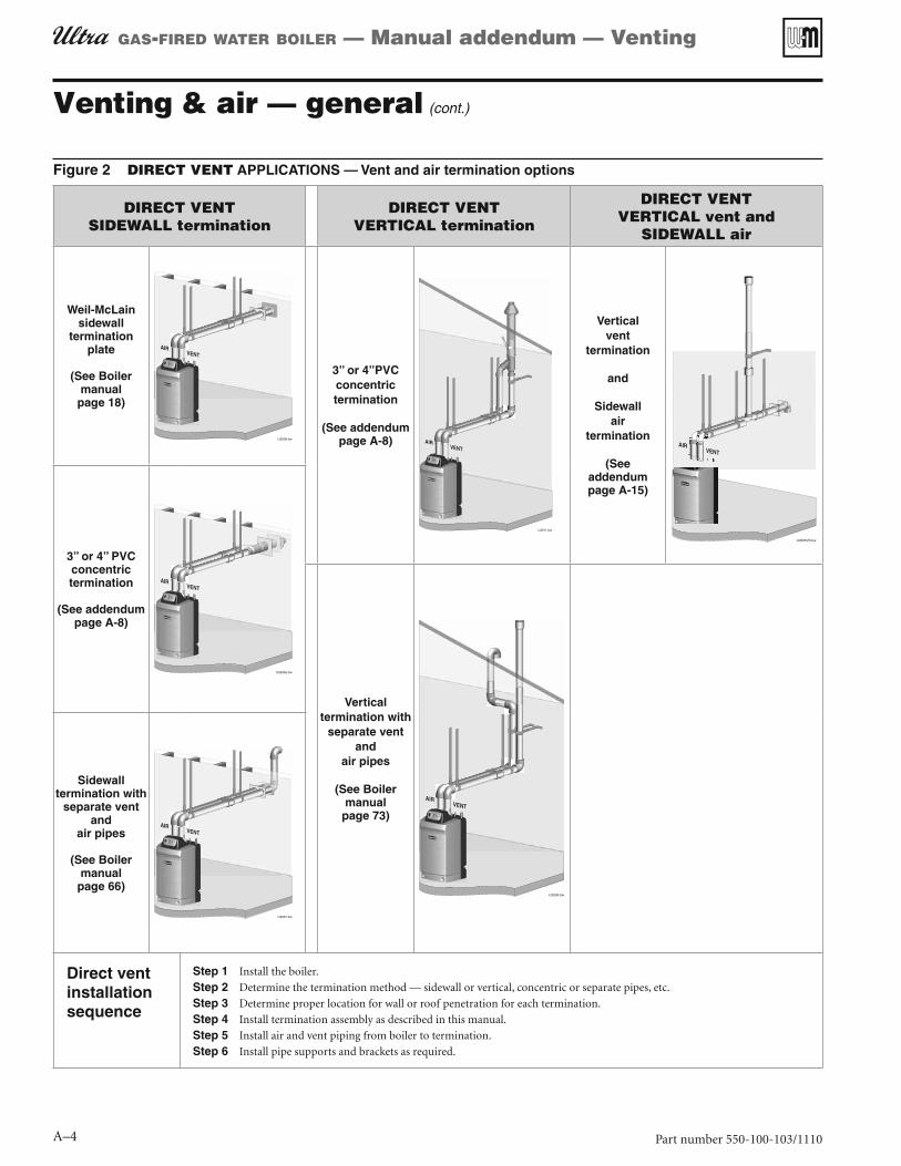
Termination location — 3” or 4” PVC Figure 6concentric termination — height above grade or snow line
Termination location — 3” or 4” PVC Figure 7concentric termination — clearances to openings
All vent and air pipes require a bird screen at each termination. Most kits do not include the screens. Purchase separately from Weil-McLain or vent kit supplier if not included.

Part number 550-100-103/1110 A–9
GAS-FIRED WATER BOILER — Manual addendum — Venting
Sidewall vent/air termination: 3” or 4” concentric (cont.)
The flue products will form a noticeable plume as they con-b. dense in cold air. Avoid areas where the plume could obstruct window views.
Prevailing winds could cause freezing of condensate and water/c. ice buildup where flue products impinge on building surfaces or plants.
Avoid possibility of accidental contact of flue products with d. people or pets.
Do not locate the terminations where wind eddies could affect e. performance or cause recirculation, such as inside building corners, near adjacent buildings or surfaces, window wells, stairwells, alcoves, courtyards or other recessed areas.
Do not terminate above any door or window or under a deck. f. Condensate can freeze, causing ice formations.
Locate or guard vent to prevent condensate damage to exterior g. finishes.
Maintain clearances as shown in 2. Figure 6, Figure 7, Figure 8 and Figure 9. Also maintain the following:
Vent must terminate:a.
At least 6 feet from adjacent walls.
No closer than 5 feet below roof overhang.
At least 7 feet above any public walkway.
At least 3 feet above any forced air intake within 10 feet.
No closer than 12 inches below or horizontally from any door or window or any other gravity air inlet.
Air inlet must terminate at least 12” above grade or snow b. line.
Do not terminate closer than 4 feet horizontally (above or be-c. low) from any electric meter, gas meter, regulator, relief valve or other equipment.
Locate terminations so they are not likely to be damaged by foreign 3. objects, such as stones or balls, or subject to buildup of leaves or sediment.
Multiple vent/air terminations
When terminating multiple Ultra boilers, terminate each vent/air 1. connection as described in this addendum.
All vent pipes and air inlets must terminate at the same height to avoid possibility of severe personal injury, death or substantial property damage.
Place wall penetrations to obtain minimum clearance as shown in 2. Figure 9 for U. S. installations. For Canadian installations, provide clearances required by CSA B149.1 or B149.2 Installation Code.
The air inlet of an Ultra boiler is part of a direct vent connection. 3. It is not classified as a forced air intake with regard to spacing from adjacent boiler vents.
Combustion air (NOT vent piping) can be manifolded as shown 4. in Boiler manual, page 55.
Termination location — 3” or 4” PVC Figure 8concentric termination — clearances to public walkway or forced air intake
Termination location — 3” or 4” PVC Figure 9concentric termination — multiple boilers — clearance from vent of one to air intake of the next
Part number 550-100-103/1110
GAS-FIRED WATER BOILER — Manual addendum — Venting
A–10
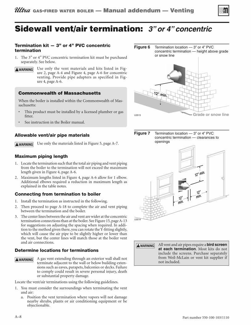
Installing and supporting the concentric Figure 10sidewall vent assembly
Install terminations — concentric pipes
Assemble the vent termination as described for vertical concentric 1. terminations, beginning on page A-12.
If necessary, you can shorten the lengths of the inner and outer pipes for a shorter finished assembly. But you must ensure the pipes butt correctly at both ends. Failure to properly assemble the concentric termination can result in flue gas recirculation, causing possible severe personal injury or death.
Wall penetration:2. 3” termination: Preferably, use a thimble with a 4½-inch hole. a. If not using a thimble, carefully use a hole saw to cut a hole not larger than 4¾ inches in diameter through the wall. The finished hole must provide a solid stop for the rain cap ribs, as shown in the inset to Figure 10.4” termination: Preferably, use a thimble with a 6-inch hole. b. If not using a thimble, carefully use a hole saw to cut a hole not larger than 6¼ inches in diameter through the wall. The finished hole must provide a solid stop for the rain cap ribs, as shown in the inset to Figure 10.
Secure the termination in place so the rain cap will butt against the 3. outside wall or outer thimble plate as shown in Figure 10.
Before beginning vent and air piping from the boiler to the con-4. centric termination, mount and secure the concentric termination as shown in Figure 10 and Figure 11.
The vent and air piping must be securely supported, and must not rest its weight on the boiler fittings. Failure to properly support the vent and air piping could result in vent piping damage, resulting in possible severe personal injury, death or substantial property damage.
The supports/bracing used must support the termination assembly to prevent slippage or movement.
The clamps used on the outside of the termination pipe must not cut into the pipe or contain sharp edges that could cause a crack to form.
When inserting the partially-assembled termination kit through the roof penetration, wrap plastic or other protection over the end of the exposed assembly to pre-vent debris from entering the pipes. If the air passages become blocked, the boiler will not operate. Once the rain cap has been cemented to the assembly, there is no way to correct the problem. The assembly would have to be replaced if it were cut to be removed and cleaned. Altering the assembly in any way could result in severe personal injury or death due to toxic flue product emis-sions.
When using AL294C stainless vent pipe, use the vent pipe manufacturer’s PVC adapter when connecting to the concentric vent attachment.
After the assembly has been positioned in the opening and all sup-5. ports have been attached, install a bird screen (purchased separately if not included with the kit) and rain cap as follows:
Place the bird screen on the end of the inner pipe as in a. Fig-ure 17, page A-14.Cement the rain cap in place as shown.b.
Sidewall vent/air termination: 3” or 4” concentric (cont.)
Figure 11 Concentric termination requirements
Concentric termination (installing termination — see
page A-8)
Install pipe supports every 5 feet on both the horizontal and vertical runs.
Install a hanger support within 6 inches of any upturn in the piping.
The concentric termination assembly must be installed before piping from the boiler to the termination.
Support the termination at the wall as shown in the termination instructions.
Slope horizontal piping downward toward the boiler at least 1/4 inch per foot.
Rotate the concentric termination Y-fitting about 30° to result in pipe centers the same as at the boiler.
Ensure that the wall material is strong enough to prevent the rain cap from being pushed inward if struck or pushed from the outside.

Part number 550-100-103/1110 A–11
GAS-FIRED WATER BOILER — Manual addendum — Venting
Vertical vent/air termination: 3” or 4” concentric
Termination kit — 3” or 4” PVC concentric termination
The 3” or 4” PVC concentric termination kit must be purchased 1. separately. See below.
Use only the vent materials and kits listed in Fig-ure 2, page A-4 and Figure 4, page A-6 for concentric venting. Provide pipe adapters as specified in Fig-ure 4, page A-6.
Allowable vent/air pipe materials
Use only the materials listed in Figure 5, page A-7.
Maximum piping length
Locate the termination such that the total air piping and vent piping 1. from the boiler to the termination will not exceed the maximum length given in Figure 4, page A-6.
Maximum lengths listed in 2. Figure 4, page A-6 allow for 1 elbow. Additional elbows required a reduction in maximum length as explained in the table notes.
Connecting from termination to boiler
Install the termination as instructed in the following. Then proceed 1. to page A-18 to complete the piping between the termination and the boiler.
Determine location
Locate the concentric vent/air termination using the following guide-lines:
The concentric vent/air assembly must terminate as shown in 1. Figure 12.
The vent and air piping connected to the termination assembly 2. must comply with the instructions in this supplement.
You must consider the surroundings when terminating the vent 3. and air:
Position the termination where vent vapors will not damage a. nearby shrubs, plants or air conditioning equipment or be objectionable.The flue products will form a noticeable plume as they con-b. dense in cold air. Avoid areas where the plume could obstruct window views.Prevailing winds could cause freezing of condensate and water/c. ice buildup where flue products impinge on building surfaces or plants.Avoid possibility of accidental contact of flue products with d. people or pets.Do not locate the termination where wind eddies could affect e. performance or cause recirculation, such as inside building corners, near adjacent buildings or surfaces, window wells, stairwells, alcoves, courtyards or other recessed areas.Locate or guard vent outlet to prevent condensate damage to f. exterior finishes.
Figure 12 Vertical termination — 3” or 4” PVC concentric
Figure 13 Vertical termination — 3” or 4” PVC concentric — multiple boilers
All vent and air pipes require a bird screen at each termination. Most kits do not include the screens. Purchase separately from Weil-McLain or vent kit supplier if not included.

Part number 550-100-103/1110
GAS-FIRED WATER BOILER — Manual addendum — Venting
A–12
Vertical vent/air termination: 3” or 4” concentric (cont.)
Maintain clearances to termination as given below:4. Vent outlet must be located:a.
At least 6 feet from adjacent walls.No closer than 5 feet below roof overhang.At least 7 feet above any public walkway.At lease 3 feet above any forced air intake within 10 feet.No closer than 12 inches below or horizontally from any door or window or any other gravity air inlet.
Air inlet must terminate at least 12 inches above the roof or b. snow line as shown in Figure 12, page A-11. (For Canada, the minimum is 18 inches.)Do not terminate closer than 4 feet horizontally from any c. electric meter, gas meter, regulator, relief valve or other equip-ment. Never terminate above or below any of these within 4 feet horizontally.
Locate termination so it is not likely to be damaged by foreign 5. objects, such as stones or balls, or subject to buildup of leaves or sediment.
Do not connect any other appliance to the vent pipe or multiple 6. boilers to a common vent pipe.
Multiple vent/air terminations
When terminating multiple Ultra boilers, install the concentric 1. vent/air termination assemblies as described in this addendum.
All vent outlets must terminate at the same height to avoid possibility of severe personal injury, death or substantial property damage.
Place roof penetrations to obtain minimum of 12 inches between 2. centers of adjacent vent pipe of another boiler for U. S. installations (see Figure 13, page A-11).
For Canadian installations, provide clearances required by CSA 3. B149.1 or B149.2 Installation Code.
The air inlet of an Ultra boiler is part of a direct vent connection. 4. It is not classified as a forced air intake with regard to spacing from adjacent boiler vents.
Prepare roof penetrations
Roof penetration hole:1. 3” termination: Cut a 5-inch diameter hole to clear the 4½-inch a. termination outside diameter.4” termination: Cut a 6.5-inch diameter hole to clear the 6-inch b. termination outside diameter.Insert a galvanized metal thimble in the vent pipe hole.c.
Follow all local codes for isolation of vent pipe when passing 2. through floors, ceilings and roofs.
Provide flashing and sealing boots sized for the concentric termi-3. nation outside diameter.
Mount the termination as shown in 4. Figure 15, page A-13.
Assembling the concentric termination
See 1. Figure 18, page A-14 for the dimensions and details of the termination assembly.
Prepare the bird screen (purchased separately if not included with 2. the kit). Cut the bird screen to size if required. If the bird screen must be trimmed, cut the bird screen to fit the outside diameter of the PVC inner pipe supplied with the termination kit.
Partially assemble the vent termination kit in the se-3. quence shown in Figure 17, page A-14.
DO NOT install the rain cap and bird screen until the assembly has been inserted through the roof and all supports have been installed. Follow instructions to cover the end of the assembly with plastic before inserting through the roof penetration to prevent debris from blocking the air passages.
Use the following procedures to prepare termination 4. components and cement together.
Deburr inside and outside of pipe ends.5.
Chamfer outside of each pipe end to ensure even cement 6. distribution when joining.
Clean all pipe ends and fittings.7.
Dry thoroughly.8.
Dry assemble entire vent or air piping to ensure proper 9. fit before assembling any joint.
For each joint:10. Handle fittings and pipes carefully to prevent con-a. tamination of surfaces.Apply primer liberally to both joint surfaces — pipe b. end and fitting socket.While primer is still damp, lightly apply approved c. cement to both surfaces in a uniform coating.Apply a second coat to both surfaces. Avoid using d. too much cement on sockets to prevent cement buildup inside.With cement still wet, insert pipe into fitting, twist-e. ing ¼ turn. Make sure pipe is fully inserted.
If necessary, you can shorten the lengths of the inner and outer pipes for a shorter finished assembly. But you must ensure the pipes butt correctly at both ends. Failure to properly as-semble the concentric termination can result in flue gas recirculation, causing possible severe personal injury or death.
Mount concentric termination
Before beginning vent and air piping from boiler, mount 1. and secure the concentric termination as shown in Fig-ure 14, page A-13, and Figure 15, page A-13.
The vent and air piping must be securely supported, and must not rest its weight on the boiler fittings. DO NOT drill or screw into either the vent pipe or air pipe. Failure to properly support the vent and air piping could result in vent piping damage, resulting in possible severe personal injury, death or substantial property damage.

Part number 550-100-103/1110 A–13
GAS-FIRED WATER BOILER — Manual addendum — Venting
Vertical vent/air termination: 3” or 4” concentric (cont.)
When inserting the partially-assembled termination kit through the roof penetration, wrap plastic or other protection over the end of the exposed assembly to prevent debris from entering the pipes. If the air passages become blocked, the boiler will not operate. Once the rain cap has been cemented to the assembly, there is no way to correct the problem. The as-sembly would have to be replaced if it were cut to be removed and cleaned. Altering the assembly in any way could result in severe personal injury or death due to toxic flue product emissions.
When using AL294C stainless vent pipe, use the vent pipe manufacturer’s PVC adapter when connecting to the con-centric vent attachment.
After the assembly has been positioned in the roof opening and all sup-2. ports have been attached, install a bird screen (purchased separately if not included with the kit) and rain cap as follows:
Place the bird screen on the end of the inner pipe as in a. Fig-ure 17, page A-14.Cement the rain cap in place as shown.b.
Vent termination support
Support the concentric vent/air termination at the roof penetration 1. as shown in Figure 15.
The supports/bracing used must support the termination assembly to prevent vertical slippage or sideways movement.The clamps used on the outside of the termination pipe must not cut into the pipe or contain sharp edges that could cause a crack to form.
Concentric termination requirementsFigure 14
Concentric termination (installing termination — see page A-11)
Install pipe supports every 5 feet on both the horizontal and vertical runs.
Install a hanger support within 6 inches of any upturn in the piping.
The concentric termination assembly must be installed before piping from the boiler to the termination.
Support the termination at the ceiling and above the roof as shown in the termination instructions.
Slope horizontal piping downward toward the boiler at least 1/4 inch per foot.
Use long-radius elbows for air piping when using 2” or 3” pipe to reduce pressure drop.
Rotate the concentric termination Y-fitting about 30° to result in pipe centers the same as at the boiler.
3” or 4” PVC concentric termination Figure 15supports
Alternate piping configuration, using (3) Figure 1645-degree elbows to obtain closer pipe centers

Part number 550-100-103/1110
GAS-FIRED WATER BOILER — Manual addendum — Venting
A–14
Concentric vent/air termination assembly
3” or 4” PVC concentric termination assembly (see kit Figure 18manufacturer’s instructions for details)
3” or 4” PVC concentric termination assembly Figure 17— DO NOT attach the rain cap until the termination has been inserted through the roof or wall and all supports have been installed.

Part number 550-100-103/1110 A–15
GAS-FIRED WATER BOILER — Manual addendum — Venting
DIRECT VENT: Vertical vent / sidewall air
Determine location
Locate the vent termination using the following guidelines:1.
The vent piping must terminate in an up-turned coupling as shown 2. in Figure 20, page A-16. The top of the coupling must be at least 1 foot above the air intake.
You must consider the surroundings when terminating the vent and 3. air:
Position the vent termination where vapors will not damage nearby a. shrubs, plants or air conditioning equipment or be objectionable.The flue products will form a noticeable plume as they condense b. in cold air. Avoid areas where the plume could obstruct window views.Prevailing winds could cause freezing of condensate and water/c. ice buildup where flue products impinge on building surfaces or plants.Avoid possibility of accidental contact of flue products with people d. or pets.Do not locate the terminations where wind eddies could affect e. performance or cause recirculation into building or appliance air intakes, such as inside building corners, near adjacent buildings or surfaces, window wells, stairwells, alcoves, courtyards or other recessed areas.Do not terminate above any door or window. Condensate can freeze, f. causing ice formations.Locate or guard vent to prevent condensate damage to exterior g. finishes.
Maintain clearances to vent termination as given below:4. Vent must terminate:a.
At least 6 feet from adjacent walls.No closer than 5 feet below roof overhang.At least 3 feet above any forced air intake within 10 feet.No closer than 12 inches below or horizontally from any door or window or any other gravity air inlet.
Do not terminate vent closer than 4 feet horizontally from any b. electric meter, gas meter, regulator, relief valve or other equip-ment. Never terminate above or below any of these within 4 feet horizontally.
Locate terminations so they are not likely to be damaged by foreign 5. objects, such as stones or balls, or subject to buildup of leaves or sedi-ment.
Do not connect any other appliance to the vent pipe. Do not connect 6. multiple boilers to a common vent pipe.
Prepare roof penetrations
Vent pipe penetration:1. Cut a hole for the vent pipe. For either combustible or noncombus-a. tible construction, size the vent pipe hole at least 0.4” larger than the vent pipe diameter:
2¾” hole for 2” PVC4” hole for 3” PVC5” hole for 4” PVC
Insert a galvanized metal thimble in the vent pipe hole.b.
Follow all local codes for isolation of vent pipe when passing through 2. floors, ceilings and roofs.
Provide flashing and sealing boots sized for the vent pipe and air 3. pipe.
Allowable vent/air pipe materials
Use only the materials listed in 1. Figure 5, page A-7.
Purchase bird screens for vent and air termina-2. tions separately. See the parts list at the end of this manual.
Maximum piping lengths
Locate the terminations such that the total air pip-1. ing and vent piping from the boiler to the termina-tion will not exceed the maximum length given in Figure 4, page A-6.
Maximum lengths listed in 2. Figure 4, page A-6 allow for 1 elbow in the air piping and 1 elbow in the vent piping. Additional elbows required a reduction in maximum length as explained in the table notes.
Direct vent: Vertical vent / sidewall airFigure 19

Part number 550-100-103/1110
GAS-FIRED WATER BOILER — Manual addendum — Venting
A–16
DIRECT VENT: Vertical vent / sidewall air (continued)
Termination and fittings
Prepare the vent termination coupling by inserting a bird screen. 1. Bird screens must be purchased separately. See the parts list at the end of this manual for part numbers.
If using 3-inch piping for an Ultra-230, cut a 4-inch bird screen a. by placing 3-inch fitting on screen and cutting around it as a template.
Maintain the required dimensions of the finished termination 2. piping as shown in Figure 20.
Multiple vent terminations
When terminating multiple Ultra boilers, terminate each vent/air 1. connection as described in this section.
Place adjacent terminations at least 6 inches apart. 2.
For Canadian installations, provide clearances required by CSA 3. B149.1 or B149.2 Installation Code.
Connecting from vent termination to boiler
Install the termination penetration as instructed in the preced-1. ing. Then proceed to page 18 to complete the piping between the termination and the boiler.
Determine location for air inlet elbow
The air inlet of an Ultra boiler is part of a direct vent connection. 1. It is not classified as a forced air intake with regard to spacing from adjacent appliance terminations.
Locate the air inlet elbow (termination) using the following 2. guidelines.
The air piping must terminate in a down-turned elbow as shown 3. in Figure 21.
Apply the configuration on the left side of a. Figure 21 unless the terminations would fail to meet minimum clearance to grade or snow line.Apply the configuration on the right side of b. Figure 21 when the terminations need to be raised higher to meet clearance to grade or snow line.The air pipe may run up the side of the building, as shown. c. The vent and air pipes must be secured with braces, and all clearances and lengths must be maintained. Space braces no further than 24 inches apart.
You must consider the surroundings when terminating the air 4. connection:
Make sure there are no obstructions for air flow. DO NOT a. locate the termination where plants could grow and cause obstruction to air flow.Do not locate the terminations where wind eddies could affect b. performance or cause recirculation with exhaust from other appliances, such as inside building corners, near adjacent build-ings or surfaces, window wells, stairwells, alcoves, courtyards or other recessed areas.Locate the air inlet termination at least 12 inches below and c. 12 inches horizontally from any appliance or building vent outlet.
Locate terminations so they are not likely to be damaged by foreign 5. objects, such as stones or balls, or subject to buildup of leaves or sediment.
Vent termination (through the roof) for direct Figure 20vent: vertical vent / sidewall air
Sidewall air inlet (termination) for direct vent: Figure 21vertical vent / sidewall air

Part number 550-100-103/1110 A–17
GAS-FIRED WATER BOILER — Manual addendum — Venting
DIRECT VENT: Vertical vent / sidewall air (continued)
Multiple air terminations
When terminating multiple Ultra boiler air connections, terminate 1. each air connection as described in this manual.
Place wall penetrations to obtain minimum clearances as instructed 2. in this manual.
Place adjacent air inlets for multiple Ultra boilers at least 6 inches 3. apart.
For Canadian installations, provide clearances required by CSA 4. B149.1 or B149.2 Installation Code.
Combustion air (NOT vent piping) can be manifolded as shown 5. in the Ultra boiler manual.
Prepare wall penetrations
Air pipe penetration:1.
a. Cut a hole for the air pipe. Size the air pipe hole as close as desired to the air pipe outside diameter.
Seal exterior openings thoroughly with exterior caulk.2.
Termination and fittings
Prepare the air termination elbow (1. Figure 21) by inserting a bird screen. Bird screens must be purchased separately. See the parts list at the end of this manual for part numbers.
Use metal plates (by installer) at inside and ouside penetrations 2. as shown in Figure 22.
If extending the air pipe out from the wall, install a cou-pling on each pipe. Mount the piping with the coupling flush with the outer plate.
Connecting from air termination to boiler
Install the terminations as instructed in the following. Then pro-1. ceed to page 18 to complete the air and vent piping between the termination and the boiler.
Sidewall air inlet installation for direct vent: Figure 22vertical vent / sidewall air
1 Air piping2 Sidewall plates, by installer
3 Bird screen (air), by installer4 Air inlet elbow
Part number 550-100-103/1110
GAS-FIRED WATER BOILER — Manual addendum — Venting
A–18
Install vent/air piping — boiler to termination
Complete termination preparation
Install vent and air terminations before proceeding. See previous 1. pages for instructions.
Installing vent and air piping
For reference in the following see:1.
Sidewall terminations: see a. Figure 11, page A-10.
Vertical terminations: see b. Figure 14, page A-13.
Work from the boiler to vent or air termination. Do not exceed 2. the lengths given in the previous pages for either the air or vent piping.
As shown in the maximum length tables, the Ultra-80 or a. Ultra-105 may be installed with either 2-inch or 3-inch vent and air piping.
As shown in the maximum length tables, the Ultra-230 may be b. installed with either 3-inch or 4-inch vent and air piping.
You must install appropriate pipe reducers, where required, at c. both the boiler and at the termination assembly.
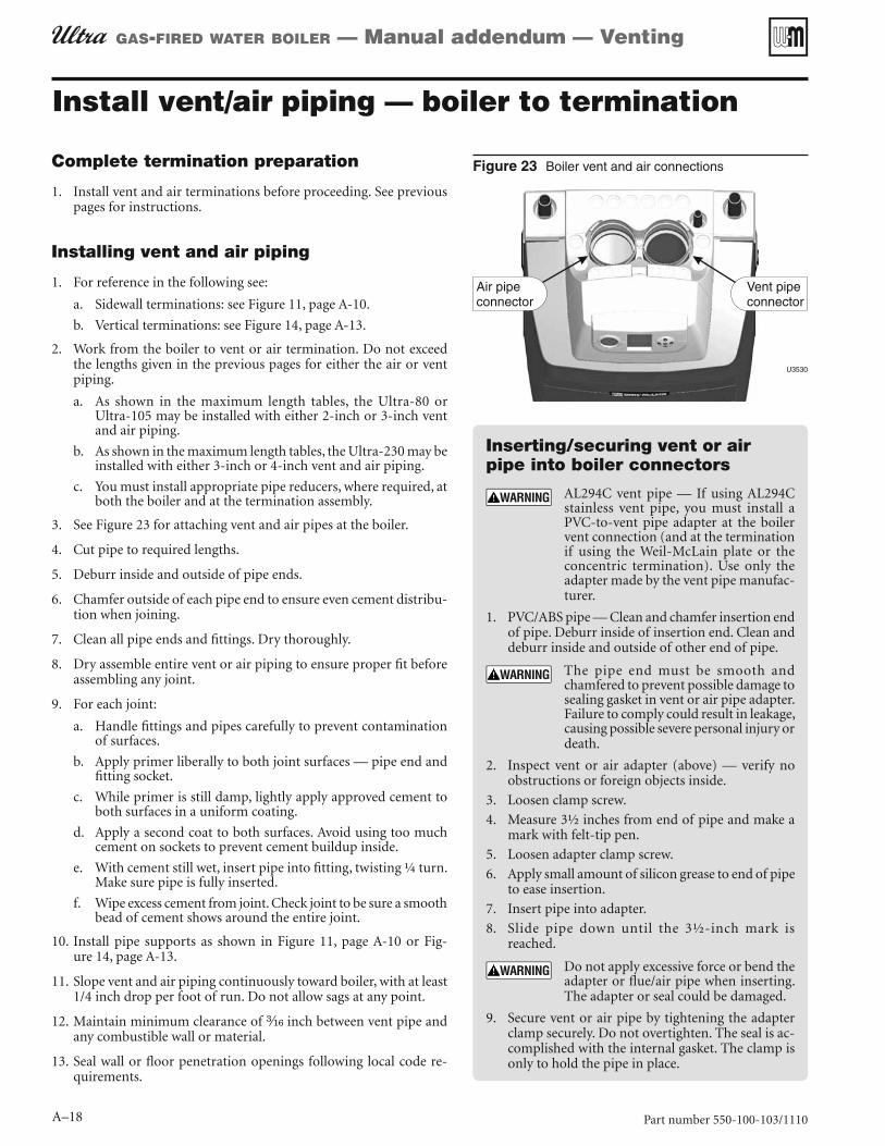
See 3. Figure 23 for attaching vent and air pipes at the boiler.
Cut pipe to required lengths.4.
Deburr inside and outside of pipe ends.5.
Chamfer outside of each pipe end to ensure even cement distribu-6. tion when joining.
Clean all pipe ends and fittings. Dry thoroughly.7.
Dry assemble entire vent or air piping to ensure proper fit before 8. assembling any joint.
For each joint:9.
Handle fittings and pipes carefully to prevent contamination a. of surfaces.
Apply primer liberally to both joint surfaces — pipe end and b. fitting socket.
While primer is still damp, lightly apply approved cement to c. both surfaces in a uniform coating.
Apply a second coat to both surfaces. Avoid using too much d. cement on sockets to prevent cement buildup inside.
With cement still wet, insert pipe into fitting, twisting ¼ turn. e. Make sure pipe is fully inserted.
Wipe excess cement from joint. Check joint to be sure a smooth f. bead of cement shows around the entire joint.
Install pipe supports as shown in 10. Figure 11, page A-10 or Fig-ure 14, page A-13.
Slope vent and air piping continuously toward boiler, with at least 11. 1/4 inch drop per foot of run. Do not allow sags at any point.
Maintain minimum clearance of 12. inch between vent pipe and any combustible wall or material.
Seal wall or floor penetration openings following local code re-13. quirements.
Boiler vent and air connectionsFigure 23
Inserting/securing vent or air pipe into boiler connectors
AL294C vent pipe — If using AL294C stainless vent pipe, you must install a PVC-to-vent pipe adapter at the boiler vent connection (and at the termination if using the Weil-McLain plate or the concentric termination). Use only the adapter made by the vent pipe manufac-turer.
PVC/ABS pipe — Clean and chamfer insertion end 1. of pipe. Deburr inside of insertion end. Clean and deburr inside and outside of other end of pipe.
The pipe end must be smooth and chamfered to prevent possible damage to sealing gasket in vent or air pipe adapter. Failure to comply could result in leakage, causing possible severe personal injury or death.
Inspect vent or air adapter (above) — verify no 2. obstructions or foreign objects inside.
Loosen clamp screw.3.
Measure 3½ inches from end of pipe and make a 4. mark with felt-tip pen.
Loosen adapter clamp screw.5.
Apply small amount of silicon grease to end of pipe 6. to ease insertion.
Insert pipe into adapter.7.
Slide pipe down until the 3½-inch mark is 8. reached.
Do not apply excessive force or bend the adapter or flue/air pipe when inserting. The adapter or seal could be damaged.
Secure vent or air pipe by tightening the adapter 9. clamp securely. Do not overtighten. The seal is ac-complished with the internal gasket. The clamp is only to hold the pipe in place.

Part number 550-100-103/1110 A–19
GAS-FIRED WATER BOILER — Manual addendum — Venting
DIRECT EXHAUST venting — general
Vent and air piping materialsSee 1. Figure 5, page A-7 for approved vent and air piping materials, for both direct exhaust and direct vent.
Use the same vent or air piping material through-out. — Do not connect different types of piping to-gether.
Vent pipingBoiler flue gases must be piped from the boiler to outside, following 1. the instructions in this manual, and compliant with all applicable codes. The vent pipe must terminate either through the sidewall or through the roof, located with the correct separation from the air termination. See the associated instructions in the following pages.
Each Ultra boiler requires a separate vent. 2. DO NOT common vent.
Combustion air openings for direct exhaust
Provide combustion air openings to boiler room and building. Combustion and ventilation air for direct exhaust boilers is provided from the boiler room. Follow all instructions in the Boiler manual and this addendum plus all applicable codes, providing combustion air open-ings as specified. Failure to comply could result in severe personal injury, death or substantial property damage.
Combustion air must be supplied through openings into the boiler 1. room, following the instructions in this manual, and compliant with all applicable codes. Read the warning in Figure 1, page A-2, and ensure the air and boiler room will not contain contaminated air.
Where the Ultra boiler shares a space with other appliances, the 2. combustion air openings must be sized to handle the combined requirements of all appliances in the space.
SIDEWALL direct exhaust optionRead and follow instructions in Boiler manual, including page 61 1. for Massachusetts installations when applicable.
Read and follow instructions in Venting addendum 2. page A-2 through page A-7.
Then go to Venting addendum 3. page A-22.
VERTICAL direct exhaust optionRead and follow instructions in Boiler manual, including page 61 1. for Massachusetts installations when applicable.
Read and follow instructions in Venting addendum 2. page A-2 through page A-7.
Then go to Venting addendum 3. page A-25.
SIDEWALL DIRECT EXHAUST
VERTICAL DIRECT EXHAUST
Every vent pipe requires a bird screen at its termi-nation. Bird screens are not supplied with the Ultra boiler. Purchase separately from Weil-McLain.

Part number 550-100-103/1110
GAS-FIRED WATER BOILER — Manual addendum — Venting
A–20
DIRECT EXHAUST — Boiler room air openings
Special considerations
Tight constructionANSI Z223.1 defines unusually tight construction where:
Walls and ceilings exposed to the outside atmo-1. sphere have a continuous water vapor retarder with a rating of 1 perm or less with openings gasketed, and . . .
Weather-stripping has been added on openable 2. windows and doors, and . . .
Caulking or sealants are applied to areas such as 3. joints around windows and door frames, between sole plates and floors, between wall-ceiling joints, between wall panels, at penetrations for plumbing, electrical, and gas lines, and in other openings.
For buildings with such construction, provide air openings into the building from outside, sized per the appropriate case in Figure 24, page 21 if appliances are to use inside air for combustion and ventilation.
Exhaust fans and air movers
The appliance space must never be under a negative pressure unless all appliances are installed as direct vent. Always provide air openings sized not only to the dimensions required for the firing rate of all appli-ances, but also to handle the air movement rate of the exhaust fans or air movers using air from the building or space.
Motorized air dampers
If the air openings are fitted with motorized dampers, electrically interlock the damper to:
Prevent the boiler from firing if the damper is not fully open.
Shut the boiler down should the damper close dur-ing boiler operation.
To accomplish this interlock, wire an isolated contact (proving the damper open) in series with the thermo-stat input to the boiler. The boiler will not start if this contact is open, and will shut down should it open during operation.
Combustion air provision
The Ultra boiler can use inside air if no contaminants are present in the boiler space. (If contaminants are likely to be present, install the boiler as a direct vent appliance, using the appropriate vent instructions in this manual.)
The boiler room must be fitted with combustion air openings large enough to provide air for all appliances in the room. Use the following information to size the openings. Ensure the installation complies with all applicable codes and standards.
Sizing combustion air openings
Air openings provide for ventilation (as well as combustion air) to prevent overheating of the boiler controls and boiler space. Air is also needed for other appliances located in the same space.
Use Figure 24, page A-21, selecting the appropriate installation condi-tions.
Air openings must be sized to handle all appliances and air movers (exhaust fans, etc.) using the air supply.
The sizing given in Figure 24, page A-21 is based on the National Fuel Gas Code, ANSI Z223.1, allowing adequate air openings for gravity-vented gas appliances (Category I) in addition to that needed for the Ultra boiler.
The air openings recommended in Figure 24, page A-21 will allow adequate ventilation and combustion air provided the boiler room is not subjected to negative pressure due to exhaust fans or other mechanical ventilation devices.
Refer to the National Fuel Gas Code for dealing with other conditions.
Free area — louver allowance
The free area of openings means the area after reduction for any installed
louvers or grilles. Be sure to consider this reduction when sizing the air openings.
Part number 550-100-103/1110 A–21
GAS-FIRED WATER BOILER — Manual addendum — Venting
DIRECT EXHAUST — Boiler room air openings (continued)
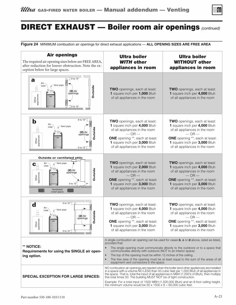
MINIMUM combustion air openings for direct exhaust applications — Figure 24 ALL OPENING SIZES ARE FREE AREA
Air openingsThe required air opening sizes below are FREE AREA, after reduction for louver obstruction. Note the ex-ception below for large spaces.
Ultra boiler WITH other
appliances in room
Ultra boiler WITHOUT other
appliances in room
TWO openings, each at least:1 square inch per 1,000 Btuh of all appliances in the room
TWO openings, each at least:1 square inch per 4,000 Btuh of all appliances in the room
TWO openings, each at least:1 square inch per 4,000 Btuh of all appliances in the room
— OR —ONE opening **, each at least:1 square inch per 3,000 Btuh of all appliances in the room
TWO openings, each at least:1 square inch per 4,000 Btuh of all appliances in the room
— OR —ONE opening **, each at least:1 square inch per 3,000 Btuh of all appliances in the room
TWO openings, each at least:1 square inch per 2,000 Btuh of all appliances in the room
— OR —ONE opening **, each at least:1 square inch per 3,000 Btuh of all appliances in the room
TWO openings, each at least:1 square inch per 4,000 Btuh of all appliances in the room
— OR —ONE opening **, each at least:1 square inch per 3,000 Btuh of all appliances in the room
TWO openings, each at least:1 square inch per 4,000 Btuh of all appliances in the room
— OR —ONE opening **, each at least:1 square inch per 3,000 Btuh of all appliances in the room
TWO openings, each at least:1 square inch per 4,000 Btuh of all appliances in the room
— OR —ONE opening **, each at least:1 square inch per 3,000 Btuh of all appliances in the room
** NOTICE:Requirements for using the SINGLE air open-ing option.
A single combustion air opening can be used for cases b, c or d above, sized as listed, provided that:
The single opening must communicate directly to the outdoors or to a space that communicates directly with outdoors (NOT to an interior space).The top of the opening must be within 12 inches of the ceiling.The free area of the opening must be at least equal to the sum of the areas of all equipment vent connectors in the space.
SPECIAL EXCEPTION FOR LARGE SPACES:
NO combustion air openings are needed when the boiler (and other appliances) are installed in a space with a volume NO LESS than 50 cubic feet per 1,000 Btuh of all appliances in the space. That is, total the input of all appliances in MBH (1,000’s of Btuh), then multiply this total times 50. The building MUST NOT be of tight construction.
Example: For a total input of 1500 MBH (1,500,000 Btuh) and an 8-foot ceiling height, the minimum volume would be 50 x 1500 x 8 = 60,000 cubic feet.

Part number 550-100-103/1110
GAS-FIRED WATER BOILER — Manual addendum — Venting
A–22
DIRECT EXHAUST — Sidewall
DIRECT EXHAUST — Sidewall Figure 25termination
DIRECT EXHAUST — Sidewall termination — installation sequence overview
Install the boiler.Step 1
Determine the proper location for wall pen-Step 2 etration for each termination.
Prepare wall penetrations before installing vent piping.
Finish by attaching external pipe and fittings as shown in the termination in-structions.
Support vertical runs on the outside of the building with brackets as shown in the termination instructions.
Install vent piping from boiler to termina-Step 3 tion.
Install a hanger support within 6 inches of any upturn in the piping.
Install pipe supports every 5 feet on both the horizontal and vertical runs.
Slope horizontal piping downward toward the boiler at least 1/4 inch per foot.
Connect the vent piping at the boiler per Step 4 instructions in this addendum.
Allowable vent pipe materials
Use only the materials listed in 1. Figure 5, page A-7.
Install a bird screen in each vent pipe termination (coupling or elbow). 2. Bird screens are not supplied with the Ultra boiler. Purchase separately from Weil-McLain.
Maximum piping length
Locate the termination such that the total vent piping from the boiler 1. to the termination will not exceed the maximum length given in Fig-ure 4, page A-6.
Maximum lengths listed in 2. Figure 4, page A-6 allow for 2 elbows. Ad-ditional elbows require a reduction in maximum length as explained in the table notes.
Determine location for sidewall termination
A gas vent extending through an exterior wall shall not terminate adjacent to the wall or below building extensions such as eaves, parapets, balconies or decks, except as otherwise instructed in this manual or local codes. Failure to comply could result in severe personal injury, death or substantial property damage.
Place the vent terminations using the following guidelines.
Terminate the vent piping with a down-turned elbow as shown in 3. Fig-ure 26, page 23. The elbow must butt against the outside wall plate. If vent piping is extended outside, install an elbow at the outer plate and continue vent piping from the elbow when snorkeling as in Figure 26, page 23 right side.
Apply the configuration on the left side of a. Figure 26 unless the termination would fail to meet minimum clearance to grade or snow line.
Apply the configuration on the right side of b. Figure 26 when the termination needs to be raised higher to meet clearance to grade or snow line.
The vent pipe may run up as high as 4 feet, as shown in c. Figure 26 right side, with no enclosure. The vent pipe must be secured with braces, and maintain all required clearances.
Space braces no further than 24 inches apart. (See WARNING below d. for extremely cold climates.)
External venting greater than 4 feet requires an enclosure around e. the vent pipe. The vent termination must exit through the enclosure as shown in Figure 26, maintaining all required clearances.
Do not exceed the maximum length of the outside vent piping shown in Figure 26. Excessive length exposed to the outside could cause freezing of condensate in the vent pipe, result-ing in potential boiler shutdown. In extremely cold climates, install an insulated chase around the vent piping, particularly when using longer lengths. The chase must allow for inspec-tion of the vent pipe, and insulation must be protected from water.

Part number 550-100-103/1110 A–23
GAS-FIRED WATER BOILER — Manual addendum — Venting
DIRECT EXHAUST — Sidewall (continued)
DIRECT EXHAUST — Sidewall — configuration options Figure 26and minimum clearances
Consider the surroundings when terminating the vent:4.
Position the vent termination where vapors will not damage a. nearby shrubs, plants or air conditioning equipment or be objectionable.
The flue products will form a noticeable plume as they con-b. dense in cold air. Avoid areas where the plume could obstruct window views.
Prevailing winds could cause freezing of condensate and water/c. ice buildup where flue products impinge on building surfaces or plants.
Avoid possibility of accidental contact of flue products with d. people or pets.
Do not locate the terminations where wind eddies could affect e. performance, such as inside building corners, near adjacent buildings or surfaces, window wells, stairwells, alcoves, court-yards or other recessed areas.
Do not terminate above any door or window or under a deck. f. Condensate can freeze, causing ice formations.
Locate or guard vent to prevent condensate damage to exterior g. finishes.
Maintain clearances as shown in the illustrations in this manual 5. section. Also maintain the following:
Vent must terminate:a.
At least 6 feet from adjacent walls.
No closer than 5 feet below roof overhang.
At lease 3 feet above any forced air intake within 10 feet.
No closer than 48 inches below or horizontally from any door or window or any other gravity air inlet.
Do not terminate closer than 4 feet horizontally from any b. electric meter, gas meter, regulator, relief valve or other equip-ment.
DIRECT EXHAUST — Sidewall — Figure 27clearances to openings
DIRECT EXHAUST — Sidewall — Figure 28clearances from vent exit to forced air intake
Because 6. Ultra boilers are Category IV appliances, the National Fuel Gas Code, ANSI Z223.1, requires that the vent must not terminate over a public walkway or over an area where condensate or vapor could create a nui-sance or hazard, or could be detrimental to the operation of regulators, relief valves, or other equipment.
Where the vent pen7. etrates an outside wall, the annular space around the penetration must be permanently sealed using approved materials to prevent entry of combustion products into the building.

Part number 550-100-103/1110
GAS-FIRED WATER BOILER — Manual addendum — Venting
A–24
DIRECT EXHAUST — Sidewall — Figure 29termination assembly — all parts by installer
1 Vent piping2 Cover plates3 Galvanized thimble
4 Vent termination elbow5 Bird screen
Locate termination so it is not likely to be damaged by foreign 8. objects, such as stones or balls, or subject to buildup of leaves or sediment.
Do not connect any other appliance to the vent pipe. Do not con-9. nect multiple boilers to a common vent pipe.
Completing the vent piping
Install vent penetration as explained in the following before install-1. ing vent piping from the boiler to the termination.
Insert piping from boiler vent connections, then attach exterior 2. termination piping.
Follow instructions beginning on 3. page A-27 to complete piping from boiler to termination.
Multiple vent terminations
When terminating multiple direct exhaust Ultra boilers, terminate 1. each vent connection as described in this manual for individual vents. Space terminations as required for best installation practices and required maintenance.
Prepare wall penetrations
Wall penetration:1.
Cut a rough opening large enough to clear the diameter of the a. metal thimble used.
Provide metal cover plates (item 2, b. Figure 29). The outer plate MUST provide a stop to prevent the vent elbow from being pushed inward. (See NOTICE at right.) Hole diameters in the metal plates must be:
2-inch PVC, CPVC or ABS — 21⁄2” hole diameter.
3-inch PVC, CPVC or ABS — 35⁄8” hole diameter.
4-inch PVC, CPVC or ABS — 45⁄8” hole diameter.
AL29-4C vent pipe and elbow — size hole large enough to clear vent pipe, but small enough to prevent the elbow from being pushed through.
Insert the galvanized metal thimble (by installer) in the vent c. pipe hole as shown in Figure 29.
Follow all local codes for isolation of vent pipe when passing 2. through floors or walls.
Termination and fittings
Prepare the vent termination elbow (1. Figure 26, page A-23) by in-serting a bird screen. Bird screens are not supplied with the Ultra boiler. Purchase separately from Weil-McLain.
You can install the vent termination using either of the configura-2. tions shown in Figure 26, page A-23.
Maintain the required dimensions of the finished termination 3. piping as shown in Figure 26, page A-23.
Seal exterior openings thoroughly with exterior caulk.4.
Do not extend exposed vent pipe outside of the building more 5. than shown in this document. Condensate could freeze and block vent pipe.
DIRECT EXHAUST — Sidewall (continued)
The Weil-McLain sidewall termination kit sup-plied with each boiler includes metal plates with two openings. These plates can be trimmed and used for direct exhaust vent termination cover plates when the vent diameter used matches the hole size in the plates provided with the boiler.

Part number 550-100-103/1110 A–25
GAS-FIRED WATER BOILER — Manual addendum — Venting
DIRECT EXHAUST — Vertical
DIRECT EXHAUST vertical terminationFigure 30
DIRECT EXHAUST — Vertical termination — installation sequence overview
Install the boiler.Step 1 Determine the proper location for wall pen-Step 2 etration for each termination.
Prepare roof penetrations before installing vent piping.
Finish by attaching external pipe and fittings as shown in the termination in-structions.
Install terminations as described in this manual.
Support vertical runs on the outside of the building with brackets as shown in the termination instructions.
Install vent piping from boiler to termina-Step 3 tion.
Install a hanger support within 6 inches of any upturn in the piping.
Install pipe supports every 5 feet on both the horizontal and vertical runs.
Slope horizontal piping downward toward the boiler at least 1/4 inch per foot.
Connect the vent piping at the boiler per Step 4 manual instructions.
Allowable vent pipe materialsUse only the materials listed in 1. Figure 5, page A-7.
Install a bird screen in each vent pipe termination (coupling or elbow). 2. Bird screens are not supplied with the Ultra boiler. Purchase separately from Weil-McLain.
Maximum piping lengthLocate the termination such that the total vent piping from the boiler 1. to the termination will not exceed the maximum length given in Fig-ure 4, page A-6.
Maximum lengths listed in 2. Figure 4, page A-6 allow for 2 elbows. Ad-ditional elbows require a reduction in maximum length as explained in the table notes.
Determine location for vertical termination
Locate the vent termination using the following guidelines:1.
The vent piping must terminate in a coupling as shown in 2. Figure 31, page 26.
Consider the surroundings when terminating the vent:3. Position the vent termination where vapors will not damage nearby a. shrubs, plants or air conditioning equipment or be objectionable.The flue products will form a noticeable plume as they condense b. in cold air. Avoid areas where the plume could obstruct window views.Prevailing winds could cause freezing of condensate and water/c. ice buildup where flue products impinge on building surfaces or plants.Avoid possibility of accidental contact of flue products with people d. or pets.Do not locate the termination where wind eddies could affect per-e. formance or cause recirculation, such as inside building corners, near adjacent buildings or surfaces, window wells, stairwells, alcoves, courtyards or other recessed areas.Locate or guard vent to prevent condensate damage to exterior f. finishes.
Maintain clearances as shown in the illustrations in this manual section. 4. Also maintain the following:
Vent must terminate:a. At least 12 inches above roof or snow line as shown in Fig-ure 31.At least 6 feet from adjacent walls.No closer than 5 feet below roof overhang.At lease 3 feet above any forced air intake within 10 feet.No closer than 48 inches below or horizontally from any door or window or any other gravity air inlet.
Do not terminate closer than 4 feet horizontally from any electric b. meter, gas meter, regulator, relief valve or other equipment.
Where the vent pen5. etrates the roof, the annular space around the penetration must be permanently sealed using approved materials to prevent entry of combustion products into the building.
Locate terminations so they are not likely to be damaged by foreign 6. objects, such as stones or balls, or subject to buildup of leaves or sedi-ment.
Do not connect any other appliance to the vent pipe. Do not connect 7. multiple boilers to a common vent pipe.
Part number 550-100-103/1110
GAS-FIRED WATER BOILER — Manual addendum — Venting
A–26
DIRECT EXHAUST — Vertical (continued)
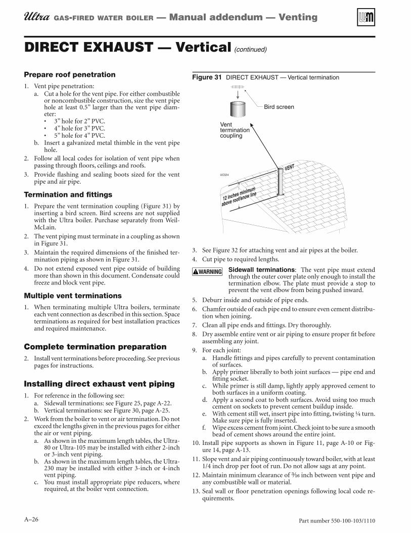
DIRECT EXHAUST — Vertical terminationFigure 31Prepare roof penetration
Vent pipe penetration:1. Cut a hole for the vent pipe. For either combustible a. or noncombustible construction, size the vent pipe hole at least 0.5” larger than the vent pipe diam-eter:
3” hole for 2” PVC.4” hole for 3” PVC.5” hole for 4” PVC.
Insert a galvanized metal thimble in the vent pipe b. hole.
Follow all local codes for isolation of vent pipe when 2. passing through floors, ceilings and roofs.
Provide flashing and sealing boots sized for the vent 3. pipe and air pipe.
Termination and fittings
Prepare the vent termination coupling (1. Figure 31) by inserting a bird screen. Bird screens are not supplied with the Ultra boiler. Purchase separately from Weil-McLain.
The vent piping must terminate in a coupling as shown 2. in Figure 31.
Maintain the required dimensions of the finished ter-3. mination piping as shown in Figure 31.
Do not extend exposed vent pipe outside of building 4. more than shown in this document. Condensate could freeze and block vent pipe.
Multiple vent terminations
When terminating multiple Ultra boilers, terminate 1. each vent connection as described in this section. Space terminations as required for best installation practices and required maintenance.
Complete termination preparationInstall vent terminations before proceeding. See previous 2. pages for instructions.
Installing direct exhaust vent pipingFor reference in the following see:1.
Sidewall terminations: see a. Figure 25, page A-22.Vertical terminations: see b. Figure 30, page A-25.
Work from the boiler to vent or air termination. Do not 2. exceed the lengths given in the previous pages for either the air or vent piping.
As shown in the maximum length tables, the Ultra-a. 80 or Ultra-105 may be installed with either 2-inch or 3-inch vent piping.As shown in the maximum length tables, the Ultra-b. 230 may be installed with either 3-inch or 4-inch vent piping.You must install appropriate pipe reducers, where c. required, at the boiler vent connection.
See 3. Figure 32 for attaching vent and air pipes at the boiler.
Cut pipe to required lengths.4.
Sidewall terminations: The vent pipe must extend through the outer cover plate only enough to install the termination elbow. The plate must provide a stop to prevent the vent elbow from being pushed inward.
Deburr inside and outside of pipe ends.5.
Chamfer outside of each pipe end to ensure even cement distribu-6. tion when joining.
Clean all pipe ends and fittings. Dry thoroughly.7.
Dry assemble entire vent or air piping to ensure proper fit before 8. assembling any joint.
For each joint:9. Handle fittings and pipes carefully to prevent contamination a. of surfaces.Apply primer liberally to both joint surfaces — pipe end and b. fitting socket.While primer is still damp, lightly apply approved cement to c. both surfaces in a uniform coating.Apply a second coat to both surfaces. Avoid using too much d. cement on sockets to prevent cement buildup inside.With cement still wet, insert pipe into fitting, twisting ¼ turn. e. Make sure pipe is fully inserted.Wipe excess cement from joint. Check joint to be sure a smooth f. bead of cement shows around the entire joint.
Install pipe supports as shown in 10. Figure 11, page A-10 or Fig-ure 14, page A-13.
Slope vent and air piping continuously toward boiler, with at least 11. 1/4 inch drop per foot of run. Do not allow sags at any point.
Maintain minimum clearance of 12. inch between vent pipe and any combustible wall or material.
Seal wall or floor penetration openings following local code re-13. quirements.

Part number 550-100-103/1110 A–27
GAS-FIRED WATER BOILER — Manual addendum — Venting
Boiler vent and air connectionsFigure 32 Inserting/securing vent or air pipe into boiler connectors
AL294C vent pipe — If using AL294C stainless vent pipe, you must install a PVC-to-vent pipe adapter at the boiler vent connection (and at the termination if using the Weil-McLain plate or the concentric termination). Use only the adapter made by the vent pipe manufacturer.
PVC/ABS pipe — Clean and chamfer insertion end of 1. pipe. Deburr inside of insertion end. Clean and deburr inside and outside of other end of pipe.
The pipe end must be smooth and chamfered to prevent possible damage to sealing gasket in vent or air pipe adapter. Failure to comply could result in leakage, causing possible severe personal injury or death.
Inspect vent or air adapter (above) — verify no obstruc-2. tions or foreign objects inside.
Loosen clamp screw.3.
Measure 3½ inches from end of pipe and make a mark 4. with felt-tip pen.
Loosen adapter clamp screw.5.
Apply small amount of silicon grease to end of pipe to 6. ease insertion.
Insert pipe into adapter.7.
Slide pipe down until the 3½-inch mark is reached.8.
Do not apply excessive force or bend the adapter or flue/air pipe when inserting. The adapter or seal could be damaged.
Secure vent or air pipe by tightening the adapter clamp 9. securely. Do not overtighten. The seal is accomplished with the internal gasket. The clamp is only to hold the pipe in place.
Air inlet opening protection: Obtain a bird screen (sized for air inlet opening) the from Weil-McLain. Insert the bird screen into the air inlet opening to prevent foreign objects from falling into the opening.
Install vent — from boiler to termination (continued)

GAS-FIRED WATER BOILER — Manual addendum — Venting