![[Rcs Iot] Rcs-e v1-2- Joyn](https://static.fdocuments.us/doc/165x107/577cd0231a28ab9e78917fbc/rcs-iot-rcs-e-v1-2-joyn.jpg)
Features - admiral-microwaves.co.uk In RF power measurement for evaluating UUT system sensitivity...
13
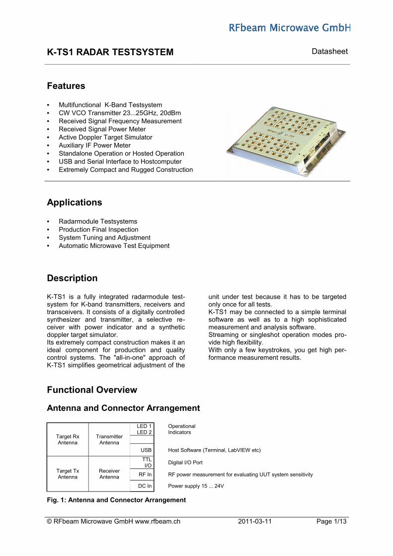
K-TS1 RADAR TESTSYSTEM Datasheet Features • Multifunctional K-Band Testsystem • CW VCO Transmitter 23...25GHz, 20dBm • Received Signal Frequency Measurement • Received Signal Power Meter • Active Doppler Target Simulator • Auxiliary IF Power Meter • Standalone Operation or Hosted Operation • USB and Serial Interface to Hostcomputer • Extremely Compact and Rugged Construction Applications • Radarmodule Testsystems • Production Final Inspection • System Tuning and Adjustment • Automatic Microwave Test Equipment Description K-TS1 is a fully integrated radarmodule test- system for K-band transmitters, receivers and transceivers. It consists of a digitally controlled synthesizer and transmitter, a selective re- ceiver with power indicator and a synthetic doppler target simulator. Its extremely compact construction makes it an ideal component for production and quality control systems. The "all-in-one" approach of K-TS1 simplifies geometrical adjustment of the unit under test because it has to be targeted only once for all tests. K-TS1 may be connected to a simple terminal software as well as to a high sophisticated measurement and analysis software. Streaming or singleshot operation modes pro- vide high flexibility. With only a few keystrokes, you get high per- formance measurement results. Functional Overview Antenna and Connector Arrangement Target Rx Antenna Transmitter Antenna LED 1 LED 2 Operational Indicators USB Host Software (Terminal, LabVIEW etc) Target Tx Antenna Receiver Antenna TTL I/O Digital I/O Port RF In RF power measurement for evaluating UUT system sensitivity DC In Power supply 15 ... 24V Fig. 1: Antenna and Connector Arrangement © RFbeam Microwave GmbH www.rfbeam.ch 2011-03-11 Page 1/13
Transcript of Features - admiral-microwaves.co.uk In RF power measurement for evaluating UUT system sensitivity...
K-TS1 RADAR TESTSYSTEM Datasheet
Features
• Multifunctional K-Band Testsystem• CW VCO Transmitter 23...25GHz, 20dBm• Received Signal Frequency Measurement • Received Signal Power Meter • Active Doppler Target Simulator • Auxiliary IF Power Meter• Standalone Operation or Hosted Operation• USB and Serial Interface to Hostcomputer• Extremely Compact and Rugged Construction
Applications
• Radarmodule Testsystems• Production Final Inspection• System Tuning and Adjustment• Automatic Microwave Test Equipment
Description
K-TS1 is a fully integrated radarmodule test-system for K-band transmitters, receivers and transceivers. It consists of a digitally controlled synthesizer and transmitter, a selective re-ceiver with power indicator and a synthetic doppler target simulator.Its extremely compact construction makes it an ideal component for production and quality control systems. The "all-in-one" approach of K-TS1 simplifies geometrical adjustment of the
unit under test because it has to be targeted only once for all tests. K-TS1 may be connected to a simple terminal software as well as to a high sophisticated measurement and analysis software.Streaming or singleshot operation modes pro-vide high flexibility. With only a few keystrokes, you get high per-formance measurement results.
Functional Overview
Antenna and Connector Arrangement
Target RxAntenna
TransmitterAntenna
LED 1LED 2
OperationalIndicators
USB Host Software (Terminal, LabVIEW etc)
Target TxAntenna
Receiver Antenna
TTLI/O
Digital I/O Port
RF In RF power measurement for evaluating UUT system sensitivity
DC In Power supply 15 ... 24V
Fig. 1: Antenna and Connector Arrangement
© RFbeam Microwave GmbH www.rfbeam.ch 2011-03-11 Page 1/13
K-TS1 RADAR TESTSYSTEM Datasheet
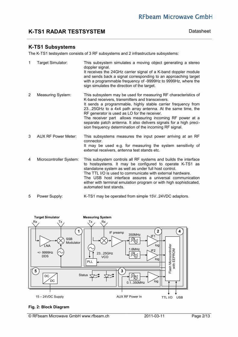
K-TS1 SubsystemsThe K-TS1 testsystem consists of 3 RF subsystems and 2 infrastructure subsystems:
1 Target Simulator: This subsystem simulates a moving object generating a stereo doppler signal. It receives the 24GHz carrier signal of a K-band doppler module and sends back a signal corresponding to an approaching target with a programmable frequency of -9999Hz to 9999Hz, where the sign simulates the direction of the target.
2 Measuring System: This subsystem may be used for measuring RF characteristics of K-band receivers, transmitters and transceivers.It sends a programmable, highly stable carrier frequency from 23...25GHz to a 4x4 path array antenna. At the same time, the RF generator is used as LO for the receiver. The receiver part allows measuring incoming RF power at a separate patch antenna. It also delivers signals for a high preci-sion frequency determination of the incoming RF signal.
3 AUX RF Power Meter: This subsystems measures the input power arriving at an RF connector. It may be used e.g. for measuring the system sensitivity of external receivers, antenna test stands etc.
4 Microcontroller System: This subsystem controls all RF systems and builds the interface to hostsystems. It may be configured to operate K-TS1 as standalone system as well as under full host control.The TTL I/O is used to communicate with external hardware.The USB host interface assures a universal communication either with terminal emulation program or with high sophisticated, automated test stands.
5 Power Supply: K-TS1 may be operated from simple 15V..24VDC adaptors.
Fig. 2: Block Diagram
© RFbeam Microwave GmbH www.rfbeam.ch 2011-03-11 Page 2/13
log
logPLL
23...25GHzVCO
+/- 9999HzDDS
SSBModulator
log
Fla
sh M
icro
con
trol
ler
with
EE
PR
OM
DC
DC
LNA
USBTTL I/OAUX RF Power In15 – 24VDC Supply
Status
Rx Tx
Target Simulator Measuring System
Tx Rx
IF1
IF2
350MHz
1.6MHz
IF preamp
0.1..350MHz
1 2
3
4
5
K-TS1 RADAR TESTSYSTEM Datasheet
CharacteristicsParameter Conditions / Notes Symbol Min Typ Max Unit
Operating conditions
Supply voltage Vcc 15 24 26 V
Supply current Transmitter active Icc 100 mA
Operating temperature Top 0 +60 °C
Storage temperature Tst -20 +80 °C
Transmitter
Transmitter frequency digitally adjustable fTX 23.000 25.000 GHz
Frequency step width fstep 1 MHz/stp
Output power EIRP PTX +13 +17 +20 dBm
Frequency drift vs temperature 0°C .. +60°C fTXDrift +/- 25 kHz/°C
Maximum frequency error 0°C .. +60°C fTXError +/- 1.2 MHz
Phase Noise @ 100kHz offset PTxNoise -95 dBc/Hz
Spurious @ 62.5kHz offset Pspur1 -25 dBc
Out of Band Spurious f<23.000GHz or f>25.000GHz Pspur2 -20 dBm
Receiver
Frequency range fRX 23.000 25.000 GHz
IF1 bandwidth Band is centered around TX frequency BWIF1 fTX+/-350 MHz
IF2 bandwidth Band is centered around TX frequency BWIF2 fTX+/-1.6 MHz
Noisefloor IF1 full bandwidth PnoiseIF1 -68 dBm
Noisefloor IF2 full bandwidth PnoiseIF2 -89 dBm
RX power indicator range IF1 Power seen from RX-Antenna PIF1 -65.0 -10.0 dBm
RX power indicator range IF2 Power seen from RX-Antenna PIF2 -86.0 -10.0 dBm
RX power detector resolution IF1 / IF2 RPRx 0.1 dB
RX power accuracy IF1 / IF2 PRXError +/- 3 dB
RX frequency detector resolution RfRx 1 MHz
Frequency measurement error fRXError +/- 1 MHz
RX frequency detector sensitivity power range for reliable acquisition PfRx -50.0 -10.0 dBm
Doppler Target
Frequency range Transmit frequency of UUT fTG 23.500 24.500 GHz
Doppler frequency range Software Adjustable fDoppler 1 9999 Hz
Aequivalent reflectivityapproximative indicationSerial# < 1108xxxxSerial# >= 1108xxxx
RCSRCS
10200
mm2
cm2
AUX Power Input
AUX bandwidth -3dB Points BWAUX 0.1 350 MHz
Noisefloor AUX full bandwidth PnoiseAUX -75.0 dBm
AUX power indicator range PAUX -72.0 +15.0 dBm
AUX power detector resolution RPAUX 0.1 dB
AUX power accuracy PAUXError +/- 3 dB
AUX input impedance Rin 50 Ohm
Host Interface
USB Virtual COM Port 38.4kB, 8N1, no handsh. PC Driver www.ftdichip.com/Drivers/VCP.htm
TTL I/O ConnectorInput TTL (internal pull up = 47k) Vllow 0 0.4 0.6 V
Output TTL @-10mA Vohigh 4.5 5 V
© RFbeam Microwave GmbH www.rfbeam.ch 2011-03-11 Page 3/13
K-TS1 RADAR TESTSYSTEM Datasheet
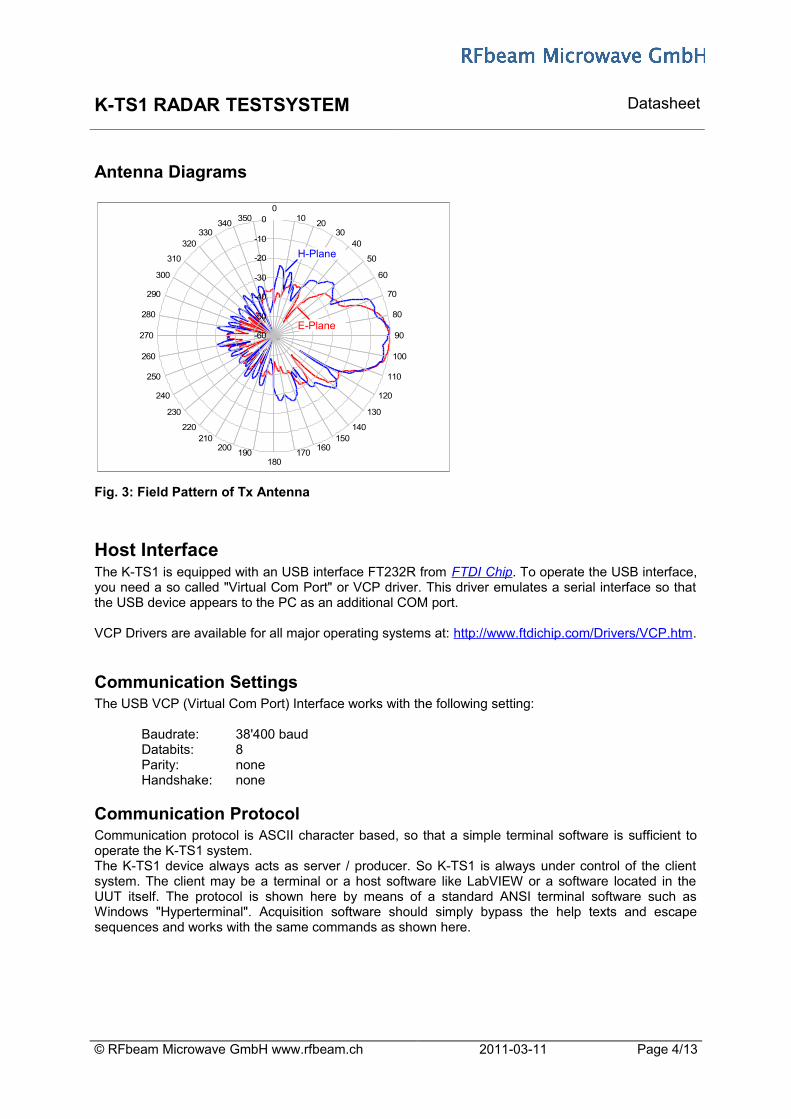
Antenna Diagrams
Fig. 3: Field Pattern of Tx Antenna
Host InterfaceThe K-TS1 is equipped with an USB interface FT232R from FTDI Chip. To operate the USB interface, you need a so called "Virtual Com Port" or VCP driver. This driver emulates a serial interface so that the USB device appears to the PC as an additional COM port.
VCP Drivers are available for all major operating systems at: http://www.ftdichip.com/Drivers/VCP.htm.
Communication SettingsThe USB VCP (Virtual Com Port) Interface works with the following setting:
Baudrate: 38'400 baudDatabits: 8Parity: noneHandshake: none
Communication ProtocolCommunication protocol is ASCII character based, so that a simple terminal software is sufficient to operate the K-TS1 system.The K-TS1 device always acts as server / producer. So K-TS1 is always under control of the client system. The client may be a terminal or a host software like LabVIEW or a software located in the UUT itself. The protocol is shown here by means of a standard ANSI terminal software such as Windows "Hyperterminal". Acquisition software should simply bypass the help texts and escape sequences and works with the same commands as shown here.
© RFbeam Microwave GmbH www.rfbeam.ch 2011-03-11 Page 4/13
-60
-50
-40
-30
-20
-10
00
1020
3040
50
60
70
80
90
100
110
120
130
140150
160170
180190
200210
220
230
240
250
260
270
280
290
300
310
320330
340350
H-Plane
E-Plane

K-TS1 RADAR TESTSYSTEM Datasheet
Startup Message and SectionsK-TS1 sends the following screen after receiving an [Enter] key from the terminal program:
RFbeam K-TS1 24GHz Test System #09160219==============================================Program Version V3.01 Jan 27 2011
[c] CW Carrier on/off : 0 [0=off, 1=on] [t] Target on/off : 0 [0=off, 1=on][f] TX-frequency : 24.125 [23.000 .. 25.000GHz] [q,w,e] Frequency ++[i,o,p] Frequency –[g] Target Frequency : 200 [-9999 .. 9999Hz]
System commands
[s] Setup[r] Store to EEPROM [b] Jump in Bootloader
Setup commands
[m] Measure f/P once[l] Measure f/P in loop [a] Cyclic table update : 0 [0=off, 1=on]
Display commands
[-] Transmitter EIRP : [dBm][-] IF1 power : [dBm] [-] IF2 power : [dBm][-] AUX power : [dBm][-] Target EIRP : [dBm]
K-TS1 measuring resultsdisplayed at command "a1"
==> K-TS1 command and result line
Fig. 4: K-TS1 output structure at a standard terminal program
K-TS1 Command Set
OverviewAll commands must be followed by an [Enter] key (ASCII 0x0d). Exception: Fast up ([q], [w], [e]) and down ([i], [o], [p]) adjustment keys. Cyclic operations can be cancelled by [Enter] or [Esc] keys.
Key Param. System Reactionc 0 | 1 K-TS1 transmits a CW carrier at a frequency set by [f]. t 0 | 1 Turns on the Doppler target simulator. The signal received at "target Rx antenna" will be amplified, SSB
modulated by the programmable target frequency and sent back via the "target Tx antenna". Tip: do not use cyclic inline display [l] when using this function. Otherwise there will possibly be distortions in the doppler signal.
f 23.000 ...25.000
Carrier frequency is set to f with a resolution of 1 MHz.Please note, that all digits including the decimal point must be entered.
q,w,e -- Fast frequency increase by 1MHz, 10MHz, 100MHz. This is very handy for frequency sweep by a host computer.
i, o, p -- Fast frequency decrease by 1MHz, 10MHz, 100MHzg -9999 ...
9999Target simulator frequency may be set with a resolution of 1Hz. The sign sets the simulated direction of the target. A positive value will simulate a forward moving target and a negative value a backward moving target. Please note, that all digits including leading zeroes must be entered.
Range for K-TS1 with Firmware smaller then V3.01 = 0 .. 4000HzRange for K-TS1 with Firmware equal or higher then V3.01 = -9999 .. 9999Hz
s -- Calibration and special mode settings values for the K-TS1 system. See Special I/O Settingsr -- Nonvolatile storage of the actual settings. Use this functions for standalone operation of K-TS1b -- This command is used for updating K-TS1 firmware. Refer to the release notes on http://www.rfbeam.ch/m -- Performs a "oneshot" measurement of Rx frequency, Rx power and Power at the "Aux" connectorl -- Performs a "cyclic" measurement of Rx frequency, Rx power and Power at the "Aux" connector. Stop cyclic
display by [Esc]. Tip: Switch doppler target off when using this function.a 0 | 1 Performs a "cyclic" measurement of internal values (refer to Fig. 4). Turn CW carrier on to get values.
Enter Enters commands and refreshes the screenEsc Escapes/stops running command [l] and refreshes the screen
© RFbeam Microwave GmbH www.rfbeam.ch 2011-03-11 Page 5/13
key description actual values
K-TS1 RADAR TESTSYSTEM Datasheet
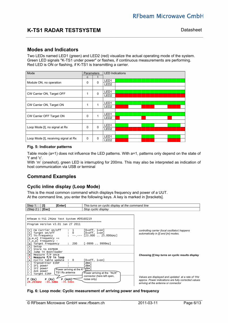
Modes and IndicatorsTwo LEDs named LED1 (green) and LED2 (red) visualize the actual operating mode of the system.Green LED signals "K-TS1 under power" or flashes, if continuous measurements are performing.Red LED is ON or flashing, if K-TS1 is transmitting a carrier.
Mode Parameters LED Indicationsc t
Module ON, no operation 0 0LED1LED2
CW Carrier ON, Target OFF 1 0LED1LED2
CW Carrier ON, Target ON 1 1LED1LED2
CW Carrier OFF Target ON 0 1LED1LED2
Loop Mode [l], no signal at Rx 0 0LED1LED2
Loop Mode [l], receiving signal at Rx 0 0LED1LED2
Fig. 5: Indicator patterns
Table mode (a=1) does not influence the LED patterns. With a=1, patterns only depend on the state of 't' and 'c'.With ‘m’ (oneshot), green LED is interrupting for 200ms. This may also be interpreted as indication of host communication via USB or terminal
Command Examples
Cyclic inline display (Loop Mode)This is the most common command which displays frequency and power of a UUT.At the command line, you enter the following keys. A key is marked in [brackets].
Step 1: [l] [Enter] This turns on cyclic display at the command line(Step 2:) [Esc] Stop cyclic display
RFbeam K-TS1 24GHz Test System #09160219==============================================Program Version V3.01 Jan 27 2011
[c] CW Carrier on/off : 1 [0=off, 1=on] [t] Target on/off : 0 [0=off, 1=on][f] TX-frequency : --.--- [23.000 .. 25.000GHz] [q,w,e] Frequency ++[i,o,p] Frequency –[g] Target Frequency : 200 [-9999 .. 9999Hz]
controlling carrier (local oscillator) happens automatically in [l] and [m] modes.
[s] Setup[r] Store to EEPROM [b] Jump in Bootloader[m] Measure f/P once[l] Measure f/P in loop [a] Cyclic table update : 0 [0=off, 1=on]
Choosing [l] key turns on cyclic results display
[-] Transmitter EIRP : [dBm][-] IF1 power : [dBm] [-] IF2 power : [dBm][-] AUX power : [dBm][-] Target EIRP : [dBm]
f (Rx) P (Rx) P (AUX)24.203GHz -35.3dBm -70.9dBm
Values are displayed and updated at a rate of 1Hz approx. Power indications are fully corrected values arriving at the antenna or connector
Fig. 6: Loop mode: Cyclic measurement of arriving power and frequency
© RFbeam Microwave GmbH www.rfbeam.ch 2011-03-11 Page 6/13
Power arriving at the K-TS1 Rx antenna Power arriving at the "AUX"
connector (here left open, noise only)

K-TS1 RADAR TESTSYSTEM Datasheet
Doppler TargetThis is an example of a test stand operation for Doppler radar transceivers. First, you had measured transmitter characteristics as in the example before. Now you like to know an approximative receiver sensitivity. K-TS1 acts as "moving target" and you measure the level of the Doppler signal at the UUT with an oscilloscope or with the software of the UUT itselfs.
(Step 1:) [Enter] If necessary, terminate a previous cyclic display(Step 2:) [c] [0] [Enter] switch off the CW carrier, it may interfere with the UUT carrierStep 3: [t] [1] [Enter] This turns on the Doppler target simulator (and causes a doppler signal at the UUT}Step 4: [g] nnnn [Enter] Set target frequency by entering 4 digits including leading zeroes. With Software
>=V3.01 you can control the simulated direction with the sign of the frequency.
RFbeam K-TS1 24GHz Test System #09160219==============================================Program Version V3.01 Jan 27 2011
[c] CW Carrier on/off : 0 [0=off, 1=on] [t] Target on/off : 1 [0=off, 1=on][f] TX-frequency : 24.125 [23.000 .. 25.000GHz] [q,w,e] Frequency ++[i,o,p] Frequency –[g] Target Frequency : 200 [-9999 .. 9999Hz]
This command activates the doppler target. It receives the carrier of the UUT, modulates it with an adjustable frequency and sends it back to the UUT. Frequency to speed relation is 44Hz / km/h
[s] Setup[r] Store to EEPROM [b] Jump in Bootloader[m] Measure f/P once[l] Measure f/P in loop [a] Cyclic table update : 0 [0=off, 1=on][-] Transmitter EIRP : [dBm][-] IF1 power : [dBm] [-] IF2 power : [dBm][-] AUX power : [dBm][-] Target EIRP : [dBm]
==>.No cyclic inline display should be activated!
Fig. 7: K-TS1 Operating as Synthetic Doppler target.
Cyclic Table Display This is an example of an in-depth analysis of Doppler radar transceivers and antenna characteristics. AUX power may be used for any power measurements of signals from –72dBm to +15dBm in a frequency range from 100kHz and 350MHz. A typical application is a readout of a high bandwidth mixer output of a radar receiver exposed to the CW carrier of the TS-1 module.Using IF1 and IF2 readouts are intended mainly for highly dynamic power measurements by ramping the CW carrier frequency and processing the value of the narrow band IF2 filter.
(Step 1:) [Enter] If necessay, terminate a previous cyclic displayStep 2: [c] [1] [Enter] This turns on the K-TS1 local oscillator and transmitterStep 3: [a] [1] [Enter] Turn on the table display mode(Step 4:) [t] [1] [Enter] This turns on the Doppler target simulator (and causes a doppler signal at the UUT}
RFbeam K-TS1 24GHz Test System #09160219==============================================Program Version V3.01 Jan 27 2011
[c] CW Carrier on/off : 1 [0=off, 1=on] [t] Target on/off : 1 [0=off, 1=on][f] TX-frequency : 24.125 [23.000 .. 25.000GHz] [q,w,e] Frequency ++[i,o,p] Frequency –[g] Target Frequency : 200 [-9999 .. 9999Hz]
In [a] mode, turning on carrier oscillator is necessary to perform power measurements.Setting of [t] is optional
[s] Setup[r] Store to EEPROM [b] Jump in Bootloader[m] Measure f/P once[l] Measure f/P in loop [a] Cyclic table update : 1 [0=off, 1=on]
Choosing [l] key turns on cyclic results display
[-] Transmitter EIRP : 20.0 [dBm][-] IF1 power : -33.6 [dBm] [-] IF2 power : -50.5 [dBm][-] AUX power : -72.9 [dBm][-] Target EIRP : -63.3 [dBm]
IF1 shows approximative Rx power got from the UUT
Target EIRP: power sent to the UUT (only if [t]=1)
==> No cyclic inline display should be activated!
Fig. 8: K-TS1 Table Display, while operating as target
© RFbeam Microwave GmbH www.rfbeam.ch 2011-03-11 Page 7/13
K-TS1 RADAR TESTSYSTEM Datasheet
Special I/O Settings
These settings are for experienced users only!Special I/O available only in Software >= V3.0 and Hardware Serial# > 0916xxxx
The special I/O appear at the TTL I/O Connection. The functionality depends on the mode of the K-TS1 system.
Normal ModeThis is the default mode, featuring all measuring functions.
Tuning Mode
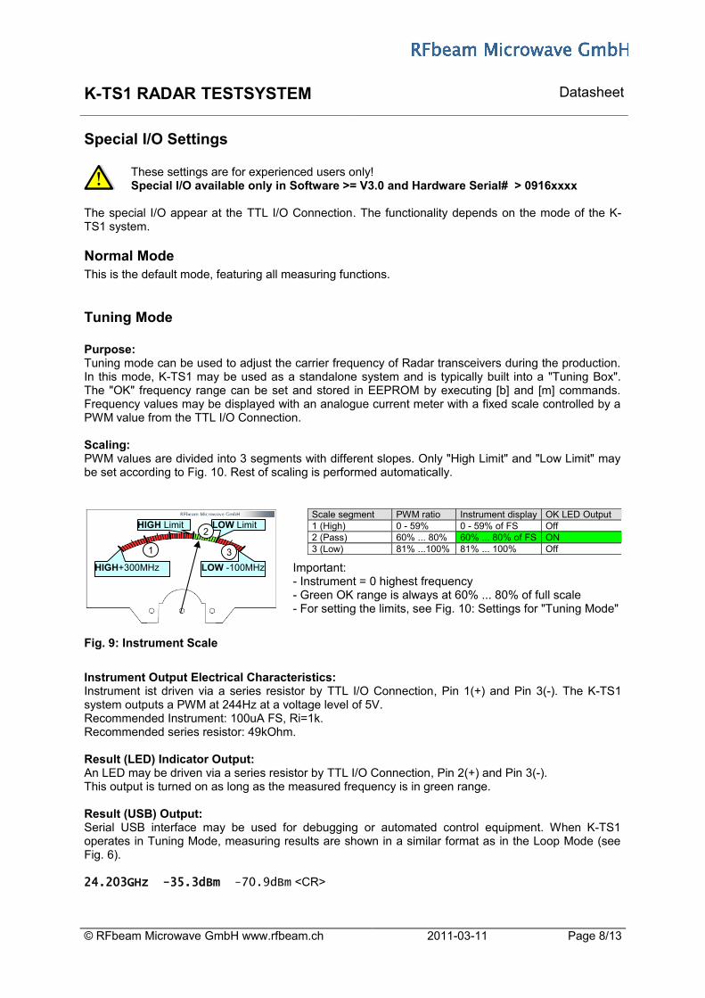
Purpose:Tuning mode can be used to adjust the carrier frequency of Radar transceivers during the production. In this mode, K-TS1 may be used as a standalone system and is typically built into a "Tuning Box". The "OK" frequency range can be set and stored in EEPROM by executing [b] and [m] commands. Frequency values may be displayed with an analogue current meter with a fixed scale controlled by a PWM value from the TTL I/O Connection.
Scaling:PWM values are divided into 3 segments with different slopes. Only "High Limit" and "Low Limit" may be set according to Fig. 10. Rest of scaling is performed automatically.
Important: - Instrument = 0 highest frequency- Green OK range is always at 60% ... 80% of full scale - For setting the limits, see Fig. 10: Settings for "Tuning Mode"
Fig. 9: Instrument Scale
Instrument Output Electrical Characteristics:Instrument ist driven via a series resistor by TTL I/O Connection, Pin 1(+) and Pin 3(-). The K-TS1 system outputs a PWM at 244Hz at a voltage level of 5V.Recommended Instrument: 100uA FS, Ri=1k.Recommended series resistor: 49kOhm.
Result (LED) Indicator Output:An LED may be driven via a series resistor by TTL I/O Connection, Pin 2(+) and Pin 3(-).This output is turned on as long as the measured frequency is in green range.
Result (USB) Output:Serial USB interface may be used for debugging or automated control equipment. When K-TS1 operates in Tuning Mode, measuring results are shown in a similar format as in the Loop Mode (see Fig. 6).
24.203GHz -35.3dBm -70.9dBm <CR>
© RFbeam Microwave GmbH www.rfbeam.ch 2011-03-11 Page 8/13
Scale segment PWM ratio Instrument display OK LED Output1 (High) 0 - 59% 0 - 59% of FS Off2 (Pass) 60% ... 80% 60% ... 80% of FS ON3 (Low) 81% ...100% 81% ... 100% Off
HIGH Limit LOW Limit
HIGH+300MHz LOW -100MHz
1
2
3
K-TS1 RADAR TESTSYSTEM Datasheet
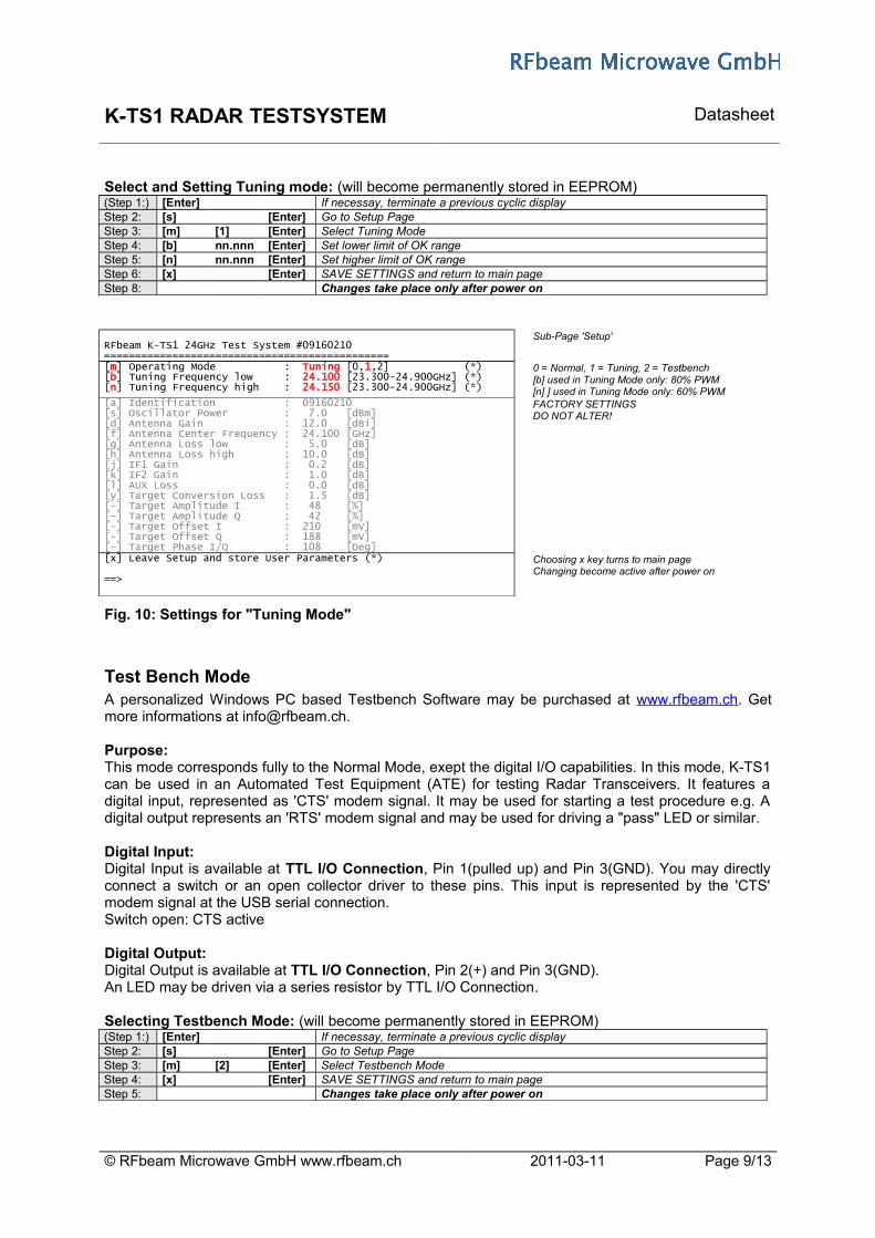
Select and Setting Tuning mode: (will become permanently stored in EEPROM)(Step 1:) [Enter] If necessay, terminate a previous cyclic displayStep 2: [s] [Enter] Go to Setup PageStep 3: [m] [1] [Enter] Select Tuning ModeStep 4: [b] nn.nnn [Enter] Set lower limit of OK rangeStep 5: [n] nn.nnn [Enter] Set higher limit of OK rangeStep 6: [x] [Enter] SAVE SETTINGS and return to main pageStep 8: Changes take place only after power on
RFbeam K-TS1 24GHz Test System #09160210==============================================
Sub-Page 'Setup'
[m] Operating Mode : Tuning [0,1,2] (*)[b] Tuning Frequency low : 24.100 [23.300-24.900GHz] (*)[n] Tuning Frequency high : 24.150 [23.300-24.900GHz] (*)
0 = Normal, 1 = Tuning, 2 = Testbench[b] used in Tuning Mode only: 80% PWM [n] ] used in Tuning Mode only: 60% PWM
[a] Identification : 09160210[s] Oscillator Power : 7.0 [dBm][d] Antenna Gain : 12.0 [dBi][f] Antenna Center Frequency : 24.100 [GHz][g] Antenna Loss low : 5.0 [dB][h] Antenna Loss high : 10.0 [dB][j] IF1 Gain : 0.2 [dB][k] IF2 Gain : 1.0 [dB][l] AUX Loss : 0.0 [dB][y] Target Conversion Loss : 1.5 [dB][-] Target Amplitude I : 48 [%][-] Target Amplitude Q : 42 [%][-] Target Offset I : 210 [mV][-] Target Offset Q : 188 [mV][-] Target Phase I/Q : 108 [Deg]
FACTORY SETTINGSDO NOT ALTER!
[x] Leave Setup and store User Parameters (*)
==>
Choosing x key turns to main pageChanging become active after power on
Fig. 10: Settings for "Tuning Mode"
Test Bench ModeA personalized Windows PC based Testbench Software may be purchased at www.rfbeam.ch. Get more informations at [email protected].
Purpose:This mode corresponds fully to the Normal Mode, exept the digital I/O capabilities. In this mode, K-TS1 can be used in an Automated Test Equipment (ATE) for testing Radar Transceivers. It features a digital input, represented as 'CTS' modem signal. It may be used for starting a test procedure e.g. A digital output represents an 'RTS' modem signal and may be used for driving a "pass" LED or similar.
Digital Input:Digital Input is available at TTL I/O Connection, Pin 1(pulled up) and Pin 3(GND). You may directly connect a switch or an open collector driver to these pins. This input is represented by the 'CTS' modem signal at the USB serial connection.Switch open: CTS active
Digital Output:Digital Output is available at TTL I/O Connection, Pin 2(+) and Pin 3(GND). An LED may be driven via a series resistor by TTL I/O Connection.
Selecting Testbench Mode: (will become permanently stored in EEPROM)(Step 1:) [Enter] If necessay, terminate a previous cyclic displayStep 2: [s] [Enter] Go to Setup PageStep 3: [m] [2] [Enter] Select Testbench ModeStep 4: [x] [Enter] SAVE SETTINGS and return to main pageStep 5: Changes take place only after power on
© RFbeam Microwave GmbH www.rfbeam.ch 2011-03-11 Page 9/13
K-TS1 RADAR TESTSYSTEM Datasheet
Application Notes
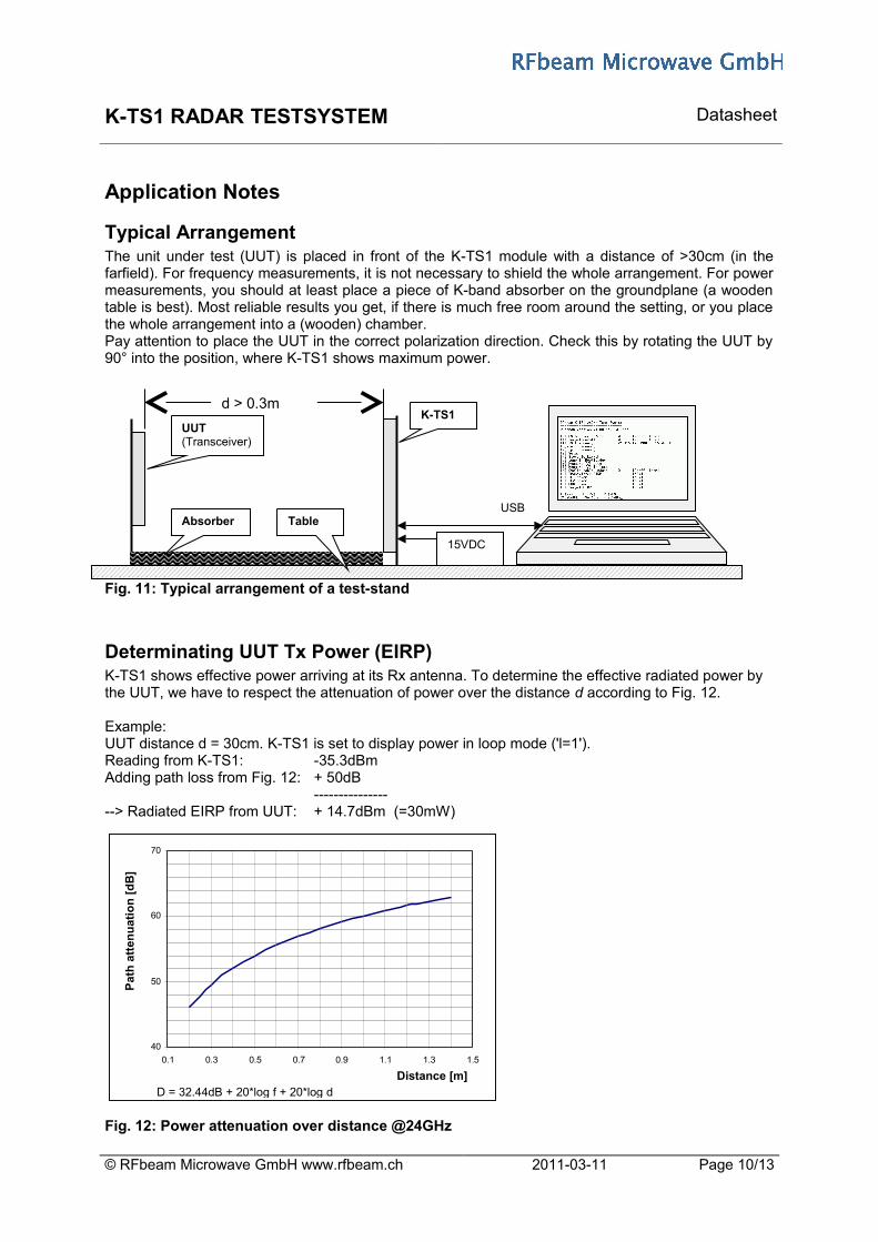
Typical ArrangementThe unit under test (UUT) is placed in front of the K-TS1 module with a distance of >30cm (in the farfield). For frequency measurements, it is not necessary to shield the whole arrangement. For power measurements, you should at least place a piece of K-band absorber on the groundplane (a wooden table is best). Most reliable results you get, if there is much free room around the setting, or you place the whole arrangement into a (wooden) chamber.Pay attention to place the UUT in the correct polarization direction. Check this by rotating the UUT by 90° into the position, where K-TS1 shows maximum power.
Fig. 11: Typical arrangement of a test-stand
Determinating UUT Tx Power (EIRP)K-TS1 shows effective power arriving at its Rx antenna. To determine the effective radiated power by the UUT, we have to respect the attenuation of power over the distance d according to Fig. 12.
Example: UUT distance d = 30cm. K-TS1 is set to display power in loop mode ('l=1').Reading from K-TS1: -35.3dBmAdding path loss from Fig. 12: + 50dB
-----------------> Radiated EIRP from UUT: + 14.7dBm (=30mW)
Fig. 12: Power attenuation over distance @24GHz
© RFbeam Microwave GmbH www.rfbeam.ch 2011-03-11 Page 10/13
40
50
60
70
0.1 0.3 0.5 0.7 0.9 1.1 1.3 1.5
Pat
h a
tten
uat
ion
[d
B]
Distance [m]D = 32.44dB + 20*log f + 20*log d
15VDC
d > 0.3m
UUT (Transceiver)
K-TS1
AbsorberUSB
Table

K-TS1 RADAR TESTSYSTEM Datasheet
Using K-TS1 as Synthetic TargetFor testing Doppler transceivers, you need normally a moving object, that reflects the transceiver's carrier and thus produces a Doppler signal in the transceiver. The same test may be accomplished by using K-TS1 in a much more comfortable and reliable fashion as "synthetic target". This results in a programmable Doppler frequency at the target's IF output and a phase shift at I/Q outputs of +90° (corresponds to an approaching target). By operating the test-stand with a known target, you may calibrate your test-stand by using the IF output signal level of the UUT as a reference.You get even more information on the behaviour of the UUT by using the K-TS1 "Table Display" mode (see Fig. 8). Based on the "Target EIRP" value, a calculation of UUT overall receiver sensitivity may be performed.
Using K-TS1 EEPROM Feature
K-TS1 as Standalone SystemYou may use K-TS1 without any host connection, if you have stored the desired operation mode in EEPROM.This feature is useful in "Synthetic Target" mode (t=1). To enter this mode permanently, enter the following commands:
(Step 1:) [Enter] If necessary, terminate a previous cyclic display(Step 2:) [c] [0] [Enter] switch off the CW carrier, it may interfere with the UUT carrierStep 3: [t] [1] [Enter] This turns on the Doppler target simulator (and causes a doppler signal at the UUT}Step 4: [g] nnnn [Enter] Enter simulator frequencyStep 5: [r] [Enter] K-TS1 answers with a short message
From now, K-TS1 automatically works as synthetic target after each power on. You may alter this setting at any time and store a new configuration in EEPROM.
You may also use a standalone K-TS1 in "Tuning Mode". See chapter Tuning Mode.
Startup with Preset ParametersFrequency and CW carrier state may be set to the desired values and stored to EEPROM by function [r]. From now, K-TS1 starts up with the new setting stored in EEPROM.
© RFbeam Microwave GmbH www.rfbeam.ch 2011-03-11 Page 11/13
K-TS1 RADAR TESTSYSTEM Datasheet
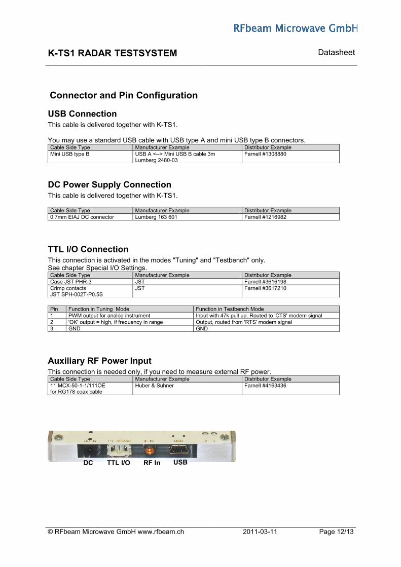
Connector and Pin Configuration
USB ConnectionThis cable is delivered together with K-TS1.
You may use a standard USB cable with USB type A and mini USB type B connectors.Cable Side Type Manufacturer Example Distributor ExampleMini USB type B USB A <--> Mini USB B cable 3m
Lumberg 2480-03Farnell #1308880
DC Power Supply ConnectionThis cable is delivered together with K-TS1.
Cable Side Type Manufacturer Example Distributor Example0.7mm EIAJ DC connector Lumberg 163 601 Farnell #1216982
TTL I/O ConnectionThis connection is activated in the modes "Tuning" and "Testbench" only.See chapter Special I/O Settings.Cable Side Type Manufacturer Example Distributor ExampleCase JST PHR-3 JST Farnell #3616198Crimp contactsJST SPH-002T-P0.5S
JST Farnell #3617210
Pin Function in Tuning Mode Function in Testbench Mode1 PWM output for analog instrument Input with 47k pull up. Routed to 'CTS' modem signal 2 'OK' output = high, if frequency in range Output, routed from 'RTS' modem signal3 GND GND
Auxiliary RF Power InputThis connection is needed only, if you need to measure external RF power. Cable Side Type Manufacturer Example Distributor Example11 MCX-50-1-1/111OEfor RG178 coax cable
Huber & Suhner Farnell #4163436
© RFbeam Microwave GmbH www.rfbeam.ch 2011-03-11 Page 12/13
DC TTL I/O RF In USB
K-TS1 RADAR TESTSYSTEM Datasheet
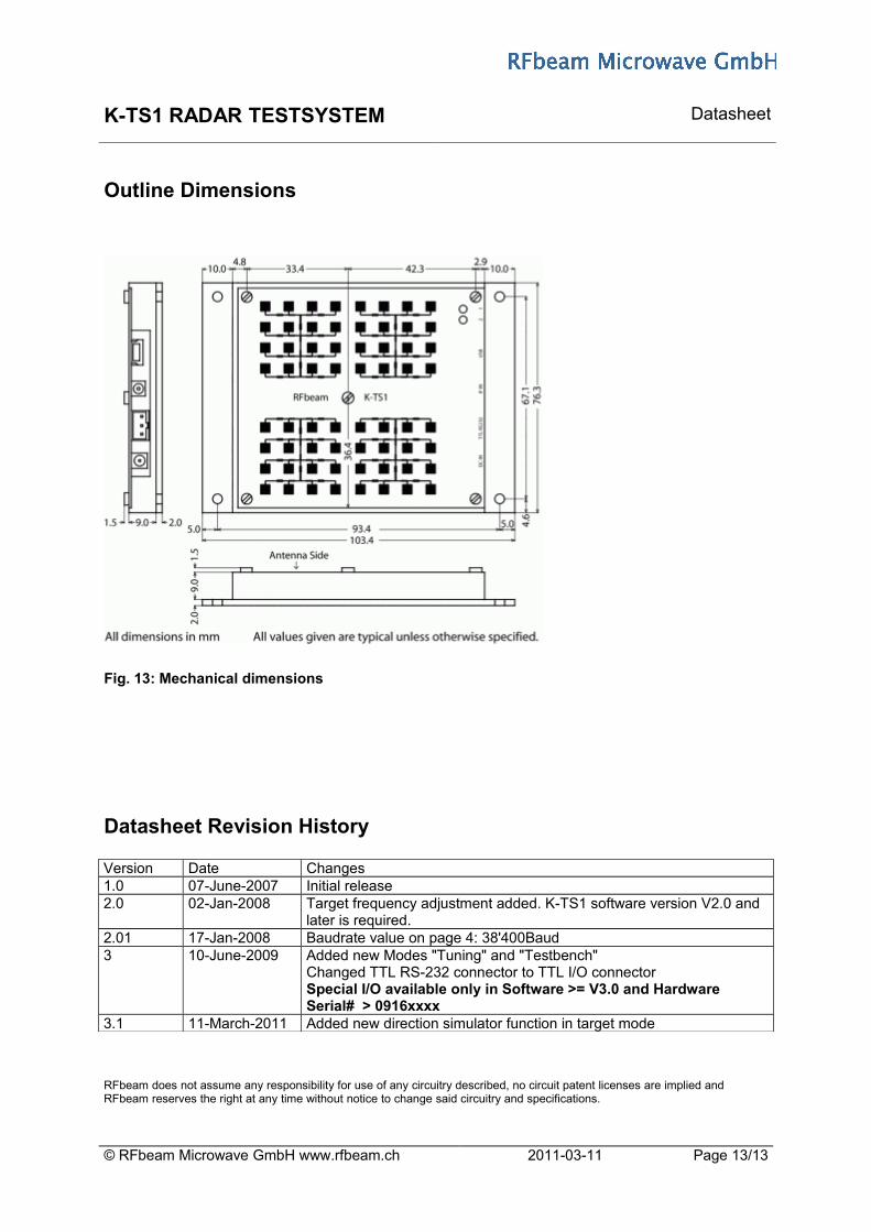
Outline Dimensions
Fig. 13: Mechanical dimensions
Datasheet Revision History
Version Date Changes1.0 07-June-2007 Initial release2.0 02-Jan-2008 Target frequency adjustment added. K-TS1 software version V2.0 and
later is required.2.01 17-Jan-2008 Baudrate value on page 4: 38'400Baud3 10-June-2009 Added new Modes "Tuning" and "Testbench"
Changed TTL RS-232 connector to TTL I/O connectorSpecial I/O available only in Software >= V3.0 and Hardware Serial# > 0916xxxx
3.1 11-March-2011 Added new direction simulator function in target mode
© RFbeam Microwave GmbH www.rfbeam.ch 2011-03-11 Page 13/13
RFbeam does not assume any responsibility for use of any circuitry described, no circuit patent licenses are implied and RFbeam reserves the right at any time without notice to change said circuitry and specifications.


![Mm2 Crazyness![1]](https://static.fdocuments.us/doc/165x107/558673bed8b42a08578b470f/mm2-crazyness1.jpg)