feature feature interaction - Home | Cheriton School of...
10
Translating Models of Automotive Features in MATLAB’s Stateflow to SMV to Detect Feature Interactions A. L. Juarez-Dominguez, MMath; University of Waterloo; Waterloo, Ontario, CANADA N. A. Day, Ph.D.; University of Waterloo; Waterloo, Ontario, CANADA R. T. Fanson, BASc.; Critical Systems Labs Inc.; Vancouver, British Columbia, CANADA Keywords: Automobile Safety, Feature Interaction, Model Checking, Modelling Abstract Feature interactions are becoming more prevalent as systems increase in complexity, and can be a source of significant risk. When features that are designed to run independently are integrated within a system, the combination of their behaviours may interfere with each other. We propose to use the formal verification technique of symbolic model checking to examine exhaustively all behaviours of an integrated set of features to detect feature interactions. In this paper, we describe how to translate automotive features described in MATLAB's Stateflow language into the input language of the model checker SMV. MATLAB's Stateflow is used extensively for designing embedded components in various domains such as the automotive and avionics industries. SMV has powerful features for model checking and has a flexible input language, in which we can describe the semantics of Stateflow and of the composition of features. The translated SMV models contain the same level of description as the design, so that the findings of our analysis can be directly understood in terms of the feature design in Stateflow. Introduction In the context of complex, electronic, software-intensive systems, a feature is a bundle of system functionality as a user recognizes it. Features are units that companies use to guide the design and marketing of the functionality offered to their customers. Features often automate a manual process or activity. An example of a feature is a collision mitigation function in a vehicle. A feature interaction occurs when features that have been developed and tested in isolation are integrated into a system, and the combination of features causes unexpected and undesired system behaviour. An example in the automotive domain is when one feature requests to apply the brakes as another feature releases the brakes. While both actions may be correct according to the intended behaviour of each feature, their interaction is undesired and potentially unsafe. A feature interaction does not arise from the failure of individual components, but from the intended functionality of correctly implemented features. Given the constant demand for functionality in products by customers, systems are becoming increasingly more complex and harder to analyze, especially when dealing with reliability and safety. Traditionally, reliability is achieved by performing extensive testing, and using techniques such as probabilistic reliability modelling (ref. 1) and Failure Modes and Effects Analysis (FMEA) (ref. 2). However, the use of FMEAs or probabilistic reliability modelling in the design process focuses on individual feature failures and does not help identify and avoid feature interactions. The feature interaction problem has been extensively studied in the telecommunications domain for the last couple of decades (ref. 3), but in that domain, the problem has not yet been completely solved. This problem is very important when dealing with safety-critical systems since an inappropriate resolution to an undesired interaction can have safety implications. For example, in the telecommunications domain, when a feature interaction occurs and it is not clear how to handle the situation, the call is just dropped; from a safety perspective, this resolution is likely acceptable since no harm is inflicted upon the users (the only exception would be the 911 feature). In contrast, in an advanced vehicle, resolving an interaction by shutting down the vehicle would not be safe for the passengers. A step toward assigning appropriate and safe resolutions to the feature interactions in safety-critical systems is to detect all the feature interactions present in the system, i.e., find all the interacting behaviours in the system where the features are being integrated. We have developed a tool to help detect feature interactions by taking models of the feature controllers designed in MATLAB’s Stateflow (ref. 4) and automatically translating them into the input language of the model checker SMV (ref. 5). The name of our tool is mdl2smv. MATLAB’s Stateflow is extensively used for designing the controllers of embedded components in the automotive and avionics industries because the models designed in Stateflow can be simulated, and code for the embedded
Transcript of feature feature interaction - Home | Cheriton School of...

Translating Models of Automotive Features in MATLAB’s Stateflow to SMV to Detect Feature Interactions
A. L. Juarez-Dominguez, MMath; University of Waterloo; Waterloo, Ontario, CANADA
N. A. Day, Ph.D.; University of Waterloo; Waterloo, Ontario, CANADA
R. T. Fanson, BASc.; Critical Systems Labs Inc.; Vancouver, British Columbia, CANADA
Keywords: Automobile Safety, Feature Interaction, Model Checking, Modelling
Abstract
Feature interactions are becoming more prevalent as systems increase in complexity, and can be a source of significant risk. When features that are designed to run independently are integrated within a system, the combination of their behaviours may interfere with each other. We propose to use the formal verification technique of symbolic model checking to examine exhaustively all behaviours of an integrated set of features to detect feature interactions. In this paper, we describe how to translate automotive features described in MATLAB's Stateflow language into the input language of the model checker SMV. MATLAB's Stateflow is used extensively for designing embedded components in various domains such as the automotive and avionics industries. SMV has powerful features for model checking and has a flexible input language, in which we can describe the semantics of Stateflow and of the composition of features. The translated SMV models contain the same level of description as the design, so that the findings of our analysis can be directly understood in terms of the feature design in Stateflow.
Introduction In the context of complex, electronic, software-intensive systems, a feature is a bundle of system functionality as a user recognizes it. Features are units that companies use to guide the design and marketing of the functionality offered to their customers. Features often automate a manual process or activity. An example of a feature is a collision mitigation function in a vehicle. A feature interaction occurs when features that have been developed and tested in isolation are integrated into a system, and the combination of features causes unexpected and undesired system behaviour. An example in the automotive domain is when one feature requests to apply the brakes as another feature releases the brakes. While both actions may be correct according to the intended behaviour of each feature, their interaction is undesired and potentially unsafe. A feature interaction does not arise from the failure of individual components, but from the intended functionality of correctly implemented features. Given the constant demand for functionality in products by customers, systems are becoming increasingly more complex and harder to analyze, especially when dealing with reliability and safety. Traditionally, reliability is achieved by performing extensive testing, and using techniques such as probabilistic reliability modelling (ref. 1) and Failure Modes and Effects Analysis (FMEA) (ref. 2). However, the use of FMEAs or probabilistic reliability modelling in the design process focuses on individual feature failures and does not help identify and avoid feature interactions. The feature interaction problem has been extensively studied in the telecommunications domain for the last couple of decades (ref. 3), but in that domain, the problem has not yet been completely solved. This problem is very important when dealing with safety-critical systems since an inappropriate resolution to an undesired interaction can have safety implications. For example, in the telecommunications domain, when a feature interaction occurs and it is not clear how to handle the situation, the call is just dropped; from a safety perspective, this resolution is likely acceptable since no harm is inflicted upon the users (the only exception would be the 911 feature). In contrast, in an advanced vehicle, resolving an interaction by shutting down the vehicle would not be safe for the passengers. A step toward assigning appropriate and safe resolutions to the feature interactions in safety-critical systems is to detect all the feature interactions present in the system, i.e., find all the interacting behaviours in the system where the features are being integrated. We have developed a tool to help detect feature interactions by taking models of the feature controllers designed in MATLAB’s Stateflow (ref. 4) and automatically translating them into the input language of the model checker SMV (ref. 5). The name of our tool is mdl2smv. MATLAB’s Stateflow is extensively used for designing the controllers of embedded components in the automotive and avionics industries because the models designed in Stateflow can be simulated, and code for the embedded
feature controllers can be automatically generated from the Stateflow models. Any change in the functionality of the features resulting from our analysis, and also any increment or error fix of the behaviour, needs to be made in the Stateflow design. Thus, we take MATLAB’s Stateflow design models directly as the input of our process. For feature interaction detection, we propose to use symbolic model checking, which is an automatic technique that searches exhaustively all the possible behaviours of a finite representation of a system. This technique can detect all feature interactions because it achieves full coverage of the system behaviours. Simulation and testing only explore some scenarios of the system. After studying the semantics of Stateflow, we decided to translate the design models into models that can be used to perform model checking in SMV since this tool is suitable for describing the semantics of individual Stateflow models and of the composition of features. The goal of this paper is to explain how each of the elements in Stateflow is automatically mapped into SMV notation by our tool mdl2smv.
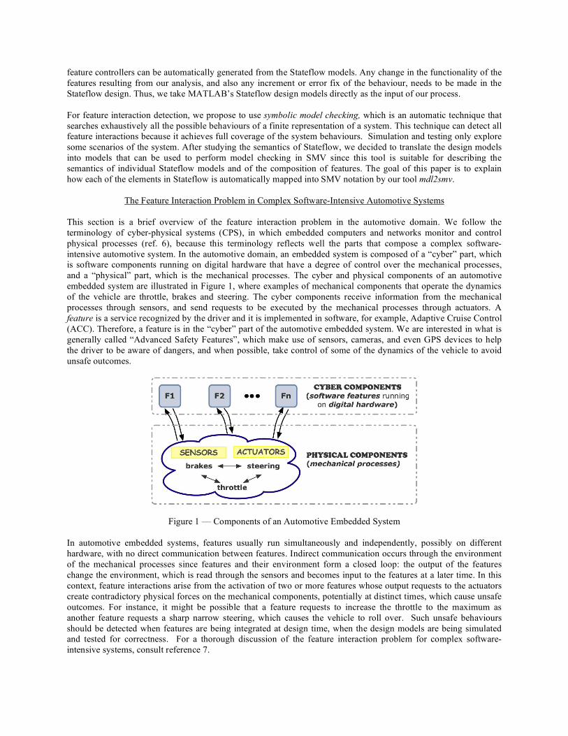
The Feature Interaction Problem in Complex Software-Intensive Automotive Systems This section is a brief overview of the feature interaction problem in the automotive domain. We follow the terminology of cyber-physical systems (CPS), in which embedded computers and networks monitor and control physical processes (ref. 6), because this terminology reflects well the parts that compose a complex software-intensive automotive system. In the automotive domain, an embedded system is composed of a “cyber” part, which is software components running on digital hardware that have a degree of control over the mechanical processes, and a “physical” part, which is the mechanical processes. The cyber and physical components of an automotive embedded system are illustrated in Figure 1, where examples of mechanical components that operate the dynamics of the vehicle are throttle, brakes and steering. The cyber components receive information from the mechanical processes through sensors, and send requests to be executed by the mechanical processes through actuators. A feature is a service recognized by the driver and it is implemented in software, for example, Adaptive Cruise Control (ACC). Therefore, a feature is in the “cyber” part of the automotive embedded system. We are interested in what is generally called “Advanced Safety Features”, which make use of sensors, cameras, and even GPS devices to help the driver to be aware of dangers, and when possible, take control of some of the dynamics of the vehicle to avoid unsafe outcomes.
Figure 1 — Components of an Automotive Embedded System In automotive embedded systems, features usually run simultaneously and independently, possibly on different hardware, with no direct communication between features. Indirect communication occurs through the environment of the mechanical processes since features and their environment form a closed loop: the output of the features change the environment, which is read through the sensors and becomes input to the features at a later time. In this context, feature interactions arise from the activation of two or more features whose output requests to the actuators create contradictory physical forces on the mechanical components, potentially at distinct times, which cause unsafe outcomes. For instance, it might be possible that a feature requests to increase the throttle to the maximum as another feature requests a sharp narrow steering, which causes the vehicle to roll over. Such unsafe behaviours should be detected when features are being integrated at design time, when the design models are being simulated and tested for correctness. For a thorough discussion of the feature interaction problem for complex software-intensive systems, consult reference 7.
A Brief Description of MATLAB’s Stateflow
In this section, we describe briefly MATLAB’s Stateflow notation, particularly the subset of the notation that is normally used when modelling the controller part of automotive features. MATLAB is the foundation for Simulink and all other MathWorks products. Simulink is software for modelling, simulating, and analyzing dynamic systems, and Stateflow is an interactive graphical design tool that works with Simulink to model and simulate event-driven systems. Stateflow models can be included in a Simulink model by placing them in Stateflow blocks, so they can be simulated. Our description is based on the Stateflow documentation (ref. 4), and Dabney and Harman (ref. 8). The syntax of Stateflow is similar to that of Statecharts (ref. 9). Like Statecharts, Stateflow uses state diagrams extended with the notions of hierarchy (states can be contained within other states), concurrency (more than one state can execute actions at the same time if appropriately triggered), and communication (broadcast mechanism for communication between concurrent components). These capabilities make the language compact yet expressive to represent complex design models succinctly. These are behavioural models because they describe the execution of the system. A Stateflow design model consists of a set of states connected by arcs called transitions. Each state has a name and can be decomposed, creating a hierarchical state diagram. The Stateflow documentation defines two kinds of decomposition for a state: (1) ‘exclusive’ or ‘OR-states’ (indicated by solid borders) and (2) ‘parallel’ or AND-states’ (indicated by dashed borders). In Stateflow, at each level of the hierarchy, only one kind of decomposition is allowed, i.e., all states at the same hierarchy level must be either OR-states or AND-states. Stateflow does not perform true concurrency for AND-states as Statecharts does. In Stateflow, AND-states execution is sequential: each AND-state reacts to the same input, but only one AND-state executes at a time because a Stateflow model runs in a single thread. Each AND-state is executed sequentially following its respective execution order. The execution order is based on the geometric position of the AND-states, where priority is assigned from top to bottom and then from left to right, according to the rules:
• The higher an AND-state’s vertical position in the diagram, the higher its priority for execution. • Among AND-states with the same vertical position, the left-most state receives highest priority.
The lower the number, the higher the priority. This order determines when each AND-state performs the actions it executes, only one state at a time for a given set of inputs, but the same set of inputs is used for all AND-states at the same level of the hierarchy. In the Section “Translating MATLAB’s Stateflow to SMV” in this paper, an example of the execution of AND-states will be shown. A Stateflow model can have data input/output ports and event input/output ports. Both data and events can be defined as local to the Stateflow model or external, i.e., communicated from the Simulink parent model through ports. Each transition’s label follows the syntax:
event[condition]/transition_action
Each part of the label is optional. The event specifies an event that causes the transition to be taken, provided the condition, if included, is true; the condition is a Boolean expression that, when true, allows a transition to be taken; the transition action is executed after the condition, if included, is true. Each transition also has a priority of execution, determined by the hierarchy level of the transition’s destination state, the type of information in its label (e.g., events have priority over conditions) and the geometric position of the transition source. If a state has no output transitions in the hierarchy, the model deadlocks. A history state (called a history junction in Stateflow) as the destination of a transition (or as the default state) means enter the most recently active state in a superstate. The In(state_name) condition function evaluates to true when the state specified as the argument is active. The following Stateflow syntax is not normally used in the creation of automotive design models: condition actions in transitions, actions within states, connective junctions, graphical functions, MATLAB functions, temporal conditions (use of temporal logic within Stateflow), and any notation that allows event broadcasting. If these syntactic elements are desired while designing a feature model, in most cases, an equivalent design can be created without these syntactic elements.

A Brief Description of SMV In this section, we describe SMV models and the subset of the SMV notation used in our translated models. Our description is based on McMillan (ref. 5). SMV (Symbolic Model Verifier) is a model checking tool that automatically verifies if a finite-state system satisfies its specification. Specifications are given in temporal logic, either linear (linear time temporal logic - LTL) or branching (computation-tree temporal logic - CTL) (ref. 10)1. Model checking is an automatic technique for verifying finite-state concurrent systems, which has been successfully used to verify complex sequential circuit designs and communication protocols. The model checking procedure searches the state space of the system exhaustively to determine if a specification is true or not. Given enough resources, the procedure will terminate with a yes/no answer. Moreover, if the answer is no, the algorithm normally provides a counterexample, i.e., a trace of the system's execution that does not satisfy the specification. A challenge that prevents the wide use of model checking is the state space explosion problem. The problem occurs in systems with a large number of interacting components, since the verification of the behaviour of these systems consist of enumerating and analyzing the set of system states that can ever be reached, so the number of system states can be too big to be handled. However, some techniques have been proposed to reduce the state space explosion problem such as abstraction and partial order reduction (ref. 11). An SMV model describes the behaviour of a system by declaring a set of variables, and writing equations for the initial values of these variables and how the variables change in each step of the model. This description of behaviour can be partitioned into a set of modules and a main module. An SMV module is a set of declarations, assignments, macros, and assertions, all of which can be re-used (similar to the concept of a subroutine). An example of the format of our generated SMV modules is shown in Figure 2. Each module can have formal parameters, which are often declared as inputs (assigned outside the module) or outputs (assigned inside the module).
Figure 2 — Example of the Format of Generated SMV Models The Declaration Section contains the input, output and local variable declarations with their types. The input and output declarations must occur before any local declarations and assignments. In the Assignment Section, a set of assignments of the form ‘name := value;’ are declared, indicating how the variables change value. Different operators can be used in the Assignment Section, and for our translator we used operators such as Boolean (“and”, “or”, “not”), conditional (“if-then-else”, “case”, “switch”), arithmetic (“+”, “-”, “*”, “/”), and
1 It is not necessary to know LTL or CTL to understand the contribution of our paper.

comparison (“=”, “<”, “>”, “>=”, “<=”). Special operators for assignments are “init” and “next”. An assignment describes the initial value of a variable using the syntax init(x) on the left-hand side (LHS) of the assignment. The syntax next(x) on the LHS is used for assignments that describe how the variable changes its value in each step. The next value of x is defined using operators and constants from the range of values that x can take given its declaration. Any variable that does not have an assignment is allowed to change non-deterministically. A macro assignment is prefixed by the keyword DEFINE and gives a concise and meaningful name to a constant or an expression. In the Assertion Section we write the properties that should hold over all executions of the system.
Translating MATLAB’s Stateflow to SMV: mdl2smv MATLAB’s Stateflow stores the information about a model in a file with a .mdl extension. We extract the necessary information from the .mdl file and translate it to the SMV modelling notation. We chose to use SMV because its notation can reflect precisely the semantics of the design models in Stateflow, and that of the composition of features. Thus, we built a direct translator from Stateflow to SMV that we call mdl2smv, which takes one text file as input and outputs another text file. As a stand-alone tool, our translator is more portable than a plug-in to MATLAB and can be used without a license for MATLAB. Our translator is written in the C programming language. We perform feature interaction detection analysis on design models so that we can apply the findings of our analysis directly to the design of the automotive components. The properties that we plan to verify are detection of feature interactions in the integration of the automotive features and the lack of errors in the design. Thus, we must refer to more than one feature during our analysis, which makes our work different from previous work on translation and analysis of Stateflow models because in those efforts the property verification analysis only considered one feature model at a time. Also, most of the previous work assumed that Stateflow’s semantics and that of Statecharts are the same, which is not the case; our work matches the semantics of Stateflow. Next, we explain how the elements of Stateflow are mapped to elements in the SMV notation. Each Stateflow feature model is a separate module in SMV. The name of the SMV module corresponds to the name of the Stateflow block. An overview of the translation process is as follows:
1. Stateflow variables are declared as SMV variables of the appropriate type; 2. Stateflow states are declared as SMV variables of enumerated type. The possible value of each superstate are
the names of its substates; 3. To translate the behavioural description, we must map Stateflow steps into SMV steps. In each step,
transitions change the values of the states and variables. We define the initial state of each superstate using an init operator and then using conditional expressions in SMV on input variables to produce the changes in the state and output variables update (using the operator next).
4. AND-state behaviour is captured through a sequence of SMV steps. 5. Feature models are integrated by synchronizing the times at which the models receive inputs.
The process of creating the SMV module is described in detail in the rest of this section. Variable Declarations: At each step in the execution of a Stateflow model, only one event can be input at a time. Therefore, we model the event inputs using one variable with an enumerated type containing the names of the possible events. The formal parameters of the SMV module include this event variable, as well as all the data that is external input or output to the Stateflow model. The module’s variables (inputs, outputs and local) are declared as enumerations, ranges, or Booleans in SMV, accordingly to the type they have in Stateflow. SMV requires its datatypes to be finite, while Stateflow allows its types to be used without value declaration. To account for this issue, our translator prompts the user when reading non-Boolean data and requests the values the data may take (range or enumeration). Only local events or data are initialized within the module, using the init operator: Booleans are initialized to false, ranges to 0 and enumerated types to a value that corresponds to the concept of “no event”. All the variables that are initialized with the init operator must be updated using an assignment with the next operator. States: Our translator declares one state variable per level of state hierarchy in the Stateflow model. Each state variable has an enumerated type consisting of the names of all of its substates. Also, we make use of the default transition information stored in the .mdl file to initialize, using the init operator, the first active state at each level of the state hierarchy. For AND-states, there is no default transition; the state with execution order of 1 is initialized to be the first active state.

Transitions: The behaviour of transitions is modelled in SMV using switch statements. At most one transition in the model can be taken in an SMV step. Figure 3 shows an example of the translation of Stateflow model with OR-states. Nested switch statements follow the hierarchy of states in the Stateflow model and check whether the model is in the source state of a transition. A simple state diagram of only one level of hierarchy would have one switch statement. Within the switch statement, there is a case for each state at the corresponding level of the hierarchy. Within each case statement, there is a series of if-then-else statements, one per transition, checking whether the event and/or condition of the transition are satisfied. The order of the if-then-else statements corresponds to the transitions’ priority of execution. If we are creating transitions within a nested switch statement (i.e., at a hierarchy level other than one), outgoing transitions from the superstate must be listed before inner transitions, in order to follow their priority of execution. Then, internal transitions are listed; first, the transition with highest priority, and consecutively creating the rest in decreasing priority.
Figure 3 — SMV File Excerpt Showing State Transition and Park Assist (PA) Stateflow Design Model Excerpt
Within each if statement, there is an assignment for every output variable. For variables that are directly changed by the transition, the assignment corresponds to the actions of the transition of the Stateflow design model. For any output variable whose value is not explicitly defined in the transition of the Stateflow model, we assign it the value it currently holds, e.g., SteerOut in the transition to FAIL in Figure 3. Also, within the if statement, there is an assignment for the next state as a result of the transition. For OR-states, the assignment corresponds to the state name that is the destination of the transition (possibly following default states for destinations that are superstates). AND-States: To translate the behaviour of AND-states in Stateflow, we must ensure (1) that AND-states execute sequentially in the order assigned to the components because Stateflow models are single-threaded, and (2) that all AND-states in the same hierarchy use the same set of inputs when checking which transitions can be taken. Thus, the execution of the behaviour of AND-states will take several SMV steps. Here, we briefly explain our solution to this problem, which was previously presented in Juarez-Dominguez, Day, and Joyce (ref. 12). To make our explanation more concrete, consider the following example, which is illustrated in Figure 4. In Figure 4, the model C has two children that are AND-states in the same hierarchy level, called A and B, with order of execution 1 and 2 respectively. If at the i-th step of execution, the model gets as input the event e1, it would check in two successive steps:
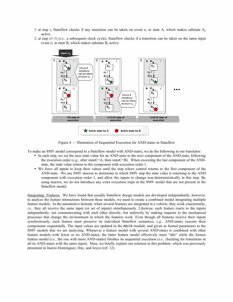
1. at step i, Stateflow checks if any transition can be taken on event e1 in state A, which makes substate A2 active.
2. at step (i+1) (i.e., a subsequent clock cycle), Stateflow checks if a transition can be taken on the same input event e1 in state B, which makes substate B2 active.
Figure 4 — Illustration of Sequential Execution for AND-states in Stateflow To make an SMV model correspond to a Stateflow model with AND-states, we do the following in our translator:
• In each step, we set the next state value for an AND-state to the next component of the AND-state, following the execution order (e.g., after stateC=A, then stateC=B). When executing the last component of the AND-state, the state value returns to the component with execution order 1.
• We force all inputs to keep their values until the step where control returns to the first component of the AND-state. We use SMV macros to determine in which SMV step the state value is returning to the AND component with execution order 1, and allow the inputs to change non-deterministically in this step. By using macros, we do not introduce any extra execution steps in the SMV model that are not present in the Stateflow model.
Integrating Features: We have found that usually Stateflow design models are developed independently, however, to analyze the feature interactions between these models, we need to create a combined model integrating multiple feature models. In the automotive domain, when several features are integrated in a vehicle, they work concurrently, i.e., they all receive the same input (or set of inputs) simultaneously. Likewise, each feature reacts to the inputs independently, not communicating with each other directly, but indirectly by making requests to the mechanical processes that change the environment in which the features work. Even though all features receive their inputs synchronously, each feature must preserve its individual Stateflow semantics, e.g., AND-states execute their components sequentially. The input values are updated in the MAIN module, and given as formal parameters to the SMV models that we are analyzing. Whenever a feature model with several AND-states is combined with other feature models with fewer or no AND-states, the latter feature model effectively must “idle” while the former feature model (i.e., the one with more AND-states) finishes its sequential execution (i.e., checking for transitions in all its AND-states with the same input). Here, we briefly explain our solution to this problem, which was previously presented in Juarez-Dominguez, Day, and Joyce (ref. 12).

Figure 5 — Illustration of Execution when Combining Multiple Features in SMV Figure 5 is an example to explain the semantics of the combination of features. In Figure 5, two features are modelled in Stateflow, named C and D. Feature model C has two children AND-states, A and B with execution order 1 and 2 respectively. When C and D are combined, they synchronize and receive new inputs when all the features are in the initial components of their AND-states. If at step i input e1 is received, C will take two steps to process the input since it has to check for transitions that can be taken in its two children AND-states, while D will only take one step to process the same input. At step i, both A and D take a transition on the input e1. At step i+1, B checks if it can take a transition while D idles. At step i+2, both feature models can process another input, say e3, because C already finished its sequential execution. When a feature model remains “idle”, it must retain the outputs it generated in its most immediate previous step of execution. To make an SMV model corresponding to the integration of several Stateflow models, we use a macro to denote when all the features are ready to receive new inputs because each feature is in the first component of all of its AND-states. Taking a transition in the first component of any AND-state is dependent on this macro being true.
Related Work In this section, we overview other efforts to translate Stateflow design models into an input representation for a tool that allows property verification. The main differences with our work are: (1) Previous work assumed that the Stateflow semantics and that of Statecharts are the same, but this is not the case, so our work matches the semantics of Stateflow during the translation process while previous efforts mostly follow Statecharts semantics (e.g., Kalita and Khargonekar (ref. 13) – Stateflow to STeP); (2) To study feature interaction, we must create a composed model of multiple features since in the automotive domain, when several features are integrated in a vehicle, they work concurrently, i.e., they all receive the same inputs simultaneously. This requirement makes our work different from previous work on translation and analysis of Stateflow models (e.g., Scaife et al. (ref. 14) – Stateflow to Lustre) since in those efforts the purpose of property verification only considered one model at a time, so they are not likely to work with our methodology for integration of feature models; (3) Some previous work translates part of the Stateflow language, leaving out necessary elements to model automotive features (e.g., Agrawal et al. (ref. 15) Stateflow to Hybrid Automata, Camera (ref. 16) – Stateflow to VHDL, Pingree and Mikk (ref. 17) – Stateflow to Spin). Banphawatthanarak and Krogh (ref. 18) translated Stateflow to SMV by creating an SMV module per OR- and AND-state, plus a module to coordinate the status of AND-states (i.e., ‘not-active’, ‘active-active’, or ‘active-wait’). Our solution is simpler and achieves the same result, but using fewer variables. Their work supported only Boolean variables, and does not support transition actions, needed in our features to model actuator request. In addition, each feature is analyzed only in isolation.

Conclusions In this paper, we introduced the main ideas behind the development of a tool to translate automatically design models in MATLAB’s Stateflow into SMV for analysis to detect feature interactions in the automotive domain. The translator described in this report, mdl2smv, has all the functionality necessary to handle the most commonly used notation for modelling the controllers of automotive embedded components in Stateflow to the input notation of the model checker SMV. The semantics of Stateflow are maintained in the generated representation in SMV. Most of the previous work assumed that Stateflow semantics and that of Statecharts were the same, but this is not the case, so our translated models match the semantics of Stateflow. The translated SMV models will allow us to verify properties of the automotive features at the same level of description as the design, so that the findings of our analysis can be directly applied to the design of the final automotive components. Our translation tool mdl2smv also implements a feature composition operator in SMV to capture the semantics of the integration of several features in a vehicle. The properties that we will verify are detection of feature interactions in the integration of the automotive features and the lack of errors in the design. During the analysis for detection of feature interactions, we must refer to more than one feature because in the automotive domain they work concurrently, i.e., they all receive the same inputs simultaneously. In contrast, other related efforts to translate Stateflow design models for property verification only considered one model at a time. As future work, we plan to use SMV on our translated models to detect feature interactions in the automotive domain. The automobile industry will continue to advance, making feature interactions an ongoing problem since vehicles continue to increase in complexity and features often evolve as a product line. Translators, such as the one we developed, which allow feature interaction analysis, are a step in the right direction to create a means to prevent undesirable interactions from ever occurring, or at least decrease the severity of their results.
References 1. M. L. Shooman. Probabilistic reliability: an engineering approach. Brooklyn Polytechnic Institute series.
McGraw-Hill, first edition, 1968. 2. N. G. Leveson. Safeware: System Safety and Computers. Addison Wesley, first edition, 2001. 3. S. Reiff-Marganiec and M. Ryan, editors. Feature Interactions in Telecommunications and Software Systems
VIII. IOS Press, 2005. 4. MathWorks Stateflow documentation, http://www.mathworks.com/access/helpdesk/help/toolbox/stateflow/,
2008. 5. K. L. McMillan. Symbolic model checking. Kluwer Academic, 1993. 6. E. A. Lee. Cyber-physical systems – are computing foundations adequate? Position Paper for the NFS Worshop
on Cyber-Physical Systems: Research, Motivation, Techniques and Roadmap, 2006. 7. A. L. Juarez-Dominguez, J. J. Joyce, and R. Debouk. Feature Interaction as a Source of Risk in Complex
Software-intensive Systems. In the Proc. of the 25th Int. System Safety Conference, 2007. 8. J. Dabney and T. L. Harman. Mastering Simulink. Pearson/Prentice Hall, 2004. 9. D. Harel. Statecharts: A visual formalism for complex systems. In the Science of Computer Programming,
8(3):231–274, 1987. 10. Z. Manna and A. Pnueli. The Temporal Logic of Reactive and Concurrent Systems: Specification. Springer-
Verlag, 1992. 11. E. M. Clarke, O. Grumberg and D.A. Peled. Model Checking. The MIT Press, 2000. 12. A. L. Juarez-Dominguez, N. A. Day, and J. J. Joyce. Modelling Feature Interactions in the Automotive Domain.
In the Proc. 2nd Workshop Modelling in Software Engineering (MiSE 2008), pages 45-50. ACM, 2008. 13. D. Kalita and P.P. Khargonekar. SF2SteP: A CAD Tool for Formal Verification of Timed Stateflow diagrams.
In IEEE Int. Sym. On Computer Aided Control Systems Design, pages 156-162, 2000. 14. N. Scaife, C. Sofronis, P. Caspi, et. al. Defining and Translating a “Safe” Subset of Simulink/Stateflow into
Lustre. In ACM Int. Conf. On Embedded Software, pages 259-268. ACM Press, 2004. 15. A. Agrawal, G. Simon, abd G. Karsai. Semantic Translation of Simulink/Stateflow Models to Hybrid Automata
using Graph Transformations. In Int. Workshop on Graph Transformation and Visual Modelling Techniques. ENTCS, 2004.
16. K. Camera. SF2VHD: A Stateflow to VHDL translator. Master’s thesis, University of California, Berkeley, 2001.

17. P. J. Pingree and E. Mikk. The HiVy Tool Set. In Computer Aided Verification (CAV), vol. 3114, pages 466-469. Spriger, 2004.
18. C. Banphawatthanarak and B. H. Krogh. Verification of stateflow diagrams using smv: sf2smv 2.0. Technical Report CMU-ECE-2000-020, Carnegie Mellon University, 2000.
Biography
A. L. Juarez-Dominguez, M. Math, Ph.D. Candidate, University of Waterloo, 200 University Avenue West, Waterloo, ON, N2L 3G1, Canada, telephone – (519) 888-4567 ext 37867, facsimile – (519) 885-1208, e-mail – [email protected]. Ms. Juarez-Dominguez is a doctoral candidate in the David R. Cheriton School of Computer Science at the University of Waterloo, working on the development of techniques and tools for safety-critical automotive systems in collaboration with General Motors Canada and Critical System Labs Inc. Her interest is in formal verification for correctness, safety and reliability of systems, particularly, distributed and embedded systems. She holds a MMath (Computer Science) from the University of Waterloo, Canada. N. A. Day, Ph.D., Associate Professor, University of Waterloo, 200 University Avenue West, Waterloo, ON, N2L 3G1, Canada, telephone – (519) 888-4567 ext 35321, facsimile – (519) 885-1208, e-mail – [email protected]. Dr. Nancy Day is an Associate Professor at the David R. Cheriton School of Computer Science of the University of Waterloo. Her research interests include formal methods, requirements specification and analysis, software engineering, and hardware verification. She is a founding member of the Waterloo Formal Methods (WatForm) Research Group. Between 1998 and 2000, she was a Postdoctoral Research Associate in the Department of Computer Science and Engineering at the Oregon Graduate Institute. She received her Ph.D. from the University of British Columbia. Her doctoral dissertation investigated analysis methods for the integrated use of multiple formal notations, with emphasis on model-oriented notations. R. T. Fanson, B. Sc., Critical Systems Labs Inc., #618-475 Howe Street, Vancouver, BC, V6C 2B3, Canada, e-mail – [email protected]. Mr. Fanson finished his undergraduate degree at the University of Waterloo in the field of Mechatronics Engineering. He became involved in the area of safety-critical systems during his work as a co-op student for Critical Systems Labs Inc. in Vancouver, BC.