Feature Description - WLAN - Huawei Description - WLAN Issue 02 Date 2013-05-15 ... Feature...
129
Enterprise Data Communication Products Feature Description - WLAN Issue 02 Date 2013-05-15 HUAWEI TECHNOLOGIES CO., LTD.
Transcript of Feature Description - WLAN - Huawei Description - WLAN Issue 02 Date 2013-05-15 ... Feature...

Enterprise Data Communication Products
Feature Description - WLAN
Issue 02
Date 2013-05-15
HUAWEI TECHNOLOGIES CO., LTD.

Copyright © Huawei Technologies Co., Ltd. 2013. All rights reserved.No part of this document may be reproduced or transmitted in any form or by any means without prior writtenconsent of Huawei Technologies Co., Ltd. Trademarks and Permissions
and other Huawei trademarks are trademarks of Huawei Technologies Co., Ltd.All other trademarks and trade names mentioned in this document are the property of their respective holders. NoticeThe purchased products, services and features are stipulated by the contract made between Huawei and thecustomer. All or part of the products, services and features described in this document may not be within thepurchase scope or the usage scope. Unless otherwise specified in the contract, all statements, information,and recommendations in this document are provided "AS IS" without warranties, guarantees or representationsof any kind, either express or implied.
The information in this document is subject to change without notice. Every effort has been made in thepreparation of this document to ensure accuracy of the contents, but all statements, information, andrecommendations in this document do not constitute a warranty of any kind, express or implied.
Huawei Technologies Co., Ltd.Address: Huawei Industrial Base
Bantian, LonggangShenzhen 518129People's Republic of China
Website: http://enterprise.huawei.com
Issue 02 (2013-05-15) Huawei Proprietary and ConfidentialCopyright © Huawei Technologies Co., Ltd.
i

About This Document
Intended AudienceThis document describes the definition, purpose, and implementation of features on enterprisedatacom products including the campus network switch, enterprise router, data center switch,and WLAN. For features supported by the device, see Configuration Guide.
This document is intended for:
l Network planning engineersl Commissioning engineersl Data configuration engineersl System maintenance engineers
Symbol ConventionsThe symbols that may be found in this document are defined as follows.
Symbol Description
DANGERIndicates a hazard with a high level or medium level of riskwhich, if not avoided, could result in death or serious injury.
WARNINGIndicates a hazard with a low level of risk which, if notavoided, could result in minor or moderate injury.
CAUTIONIndicates a potentially hazardous situation that, if notavoided, could result in equipment damage, data loss,performance deterioration, or unanticipated results.
TIP Provides a tip that may help you solve a problem or save time.
NOTE Provides additional information to emphasize or supplementimportant points in the main text.
Enterprise Data Communication ProductsFeature Description - WLAN About This Document
Issue 02 (2013-05-15) Huawei Proprietary and ConfidentialCopyright © Huawei Technologies Co., Ltd.
ii

Command ConventionsThe command conventions that may be found in this document are defined as follows.
Convention Description
Boldface The keywords of a command line are in boldface.
Italic Command arguments are in italics.
[ ] Items (keywords or arguments) in brackets [ ] are optional.
{ x | y | ... } Optional items are grouped in braces and separated byvertical bars. One item is selected.
[ x | y | ... ] Optional items are grouped in brackets and separated byvertical bars. One item is selected or no item is selected.
{ x | y | ... }* Optional items are grouped in braces and separated byvertical bars. A minimum of one item or a maximum of allitems can be selected.
[ x | y | ... ]* Optional items are grouped in brackets and separated byvertical bars. You can select one or several items, or selectno item.
&<1-n> The parameter before the & sign can be repeated 1 to n times.
# A line starting with the # sign is comments.
Change HistoryChanges between document issues are cumulative. Therefore, the latest document versioncontains all updates made to previous versions.
Changes in Issue 02 (2013-05-15)This version has the following updates:
The following information is modified:
l Descriptions and figures are optimized, improving availability.
Changes in Issue 01 (2012-09-30)Initial commercial release.
Enterprise Data Communication ProductsFeature Description - WLAN About This Document
Issue 02 (2013-05-15) Huawei Proprietary and ConfidentialCopyright © Huawei Technologies Co., Ltd.
iii

Contents
About This Document.....................................................................................................................ii
1 WLAN Basics..................................................................................................................................11.1 Introduction to WLAN...................................................................................................................................................21.2 Principles........................................................................................................................................................................21.2.1 Concepts......................................................................................................................................................................21.2.2 802.11 Standards.........................................................................................................................................................41.2.3 WLAN Architecture....................................................................................................................................................91.2.4 AP Login....................................................................................................................................................................111.2.5 STA Access...............................................................................................................................................................151.2.6 Data Forwarding Mode..............................................................................................................................................181.3 Applications..................................................................................................................................................................221.3.1 WLAN Networking Application on Medium- and Large-sized Campus Networks.................................................221.3.2 WLAN Networking Application on Small Campus Networks.................................................................................241.3.3 WLAN Networking Application in Enterprise Branches..........................................................................................251.3.4 SOHO WLAN Networking Application...................................................................................................................261.4 References....................................................................................................................................................................26
2 WLAN Security............................................................................................................................282.1 Introduction to WLAN Security...................................................................................................................................292.2 Perimeter Security Principles.......................................................................................................................................292.2.1 Wireless Intrusion Detection.....................................................................................................................................292.2.2 Wireless Intrusion Prevention...................................................................................................................................312.2.3 Attack Detection........................................................................................................................................................322.2.4 Defense Against Brute Force Attacks on PSK..........................................................................................................342.3 User Access Security Principles...................................................................................................................................352.3.1 Security Policy...........................................................................................................................................................352.3.1.1 WEP........................................................................................................................................................................352.3.1.2 WPA/WPA2...........................................................................................................................................................352.3.1.3 WAPI......................................................................................................................................................................412.3.2 STA Blacklist and Whitelist......................................................................................................................................462.4 Service Security Principles...........................................................................................................................................472.4.1 User Isolation.............................................................................................................................................................472.4.2 Terminal Type Identification.....................................................................................................................................48
Enterprise Data Communication ProductsFeature Description - WLAN Contents
Issue 02 (2013-05-15) Huawei Proprietary and ConfidentialCopyright © Huawei Technologies Co., Ltd.
iv

2.5 Applications..................................................................................................................................................................502.5.1 WIDS/WIPS..............................................................................................................................................................502.5.2 Security Policy...........................................................................................................................................................512.5.3 STA Blacklist and Whitelist......................................................................................................................................522.6 References....................................................................................................................................................................53
3 Radio Resource Management....................................................................................................543.1 Introduction to Radio Resource Management..............................................................................................................553.2 Principles......................................................................................................................................................................553.2.1 Radio Calibration.......................................................................................................................................................553.2.2 Load Balancing..........................................................................................................................................................603.2.3 5G-Prior Access.........................................................................................................................................................633.2.4 Spectrum Analysis.....................................................................................................................................................633.3 References....................................................................................................................................................................65
4 WLAN Reliability........................................................................................................................664.1 Introduction to WLAN Reliability...............................................................................................................................674.2 Principles......................................................................................................................................................................674.2.1 Non-Stop AP Operation After CAPWAP Link Disconnection.................................................................................674.2.2 Dual-Link Backup.....................................................................................................................................................694.2.3 AC Hot Standby.........................................................................................................................................................714.3 Applications..................................................................................................................................................................734.3.1 Application of Non-Stop AP Operation After CAPWAP Link Disconnection.........................................................734.3.2 Application of Dual-Link Backup.............................................................................................................................744.3.3 Application of AC Hot Standby................................................................................................................................754.4 References....................................................................................................................................................................77
5 WLAN Roaming...........................................................................................................................785.1 Introduction to WLAN Roaming..................................................................................................................................795.2 Principles......................................................................................................................................................................805.2.1 Roaming Between APs in the Same Service VLAN.................................................................................................805.2.2 Roaming Between APs in Different Service VLANs...............................................................................................825.2.3 Key Negotiation Between STA and AP....................................................................................................................835.3 References....................................................................................................................................................................84
6 WLAN QoS...................................................................................................................................856.1 Introduction to WLAN QoS.........................................................................................................................................866.2 Principles......................................................................................................................................................................866.2.1 WMM........................................................................................................................................................................876.2.2 Priority Mapping........................................................................................................................................................916.2.3 Traffic Policing..........................................................................................................................................................926.3 Applications..................................................................................................................................................................966.4 References....................................................................................................................................................................97
7 WLAN WDS.................................................................................................................................98
Enterprise Data Communication ProductsFeature Description - WLAN Contents
Issue 02 (2013-05-15) Huawei Proprietary and ConfidentialCopyright © Huawei Technologies Co., Ltd.
v

7.1 Introduction to WDS....................................................................................................................................................997.2 Principles......................................................................................................................................................................997.3 Applications................................................................................................................................................................1037.4 References..................................................................................................................................................................105
8 WLAN Mesh...............................................................................................................................1068.1 Introduction to WLAN Mesh.....................................................................................................................................1078.2 Principles....................................................................................................................................................................1078.3 Applications................................................................................................................................................................1128.4 References..................................................................................................................................................................114
9 WLAN Positioning....................................................................................................................1159.1 Introduction to Wireless Positioning..........................................................................................................................1169.2 Principles....................................................................................................................................................................1169.2.1 WLAN tag positioning............................................................................................................................................1169.2.2 Terminal Positioning...............................................................................................................................................1199.3 References..................................................................................................................................................................122
Enterprise Data Communication ProductsFeature Description - WLAN Contents
Issue 02 (2013-05-15) Huawei Proprietary and ConfidentialCopyright © Huawei Technologies Co., Ltd.
vi

1 WLAN Basics
About This Chapter
1.1 Introduction to WLAN
1.2 Principles
1.3 Applications
1.4 References
Enterprise Data Communication ProductsFeature Description - WLAN 1 WLAN Basics
Issue 02 (2013-05-15) Huawei Proprietary and ConfidentialCopyright © Huawei Technologies Co., Ltd.
1
1.1 Introduction to WLAN
DefinitionA wireless local area network (WLAN) is a network that uses wireless channels such as radiowaves, laser, and infrared rays to replace the transmission media used on a wired LAN. TheWLAN technology described in this document is implemented based on 802.11 standards. Thatis, a WLAN is a network that uses high-frequency signals (for example, 2.4 GHz or 5 GHzsignals) as transmission media.
802.11 was originally a wireless LAN communications standard defined by the Institute ofElectrical and Electronics Engineers (IEEE) in 1997. The IEEE then made amendments to thestandard, forming the 802.11 family, including 802.11, 802.11a, 802.11b, 802.11e, 802.11g,802.11i, and 802.11n.
PurposeWired LANs use wired cables or optical fibers as transmission media, which are expensive andhave fixed locations. As people have increasing requirements on network mobility, wired LANscannot meet these requirements. WLAN technology is then developed. Currently, WLAN hasbecome a cost-efficient network access mode. WLAN technology allows you to easily access awireless network and move around within the coverage of the wireless network.
Benefitsl High network mobility: WLANs can be connected easily, which is not limited by cable and
port positions. WLANs especially apply to scenarios such as office buildings, airport halls,resorts, hotels, stadiums, and cafes.
l Flexible network deployment: WLANs can provide wireless network coverage in placeswhere cables are difficult to deploy, such as subways and highways. This solution reducescables, offers ease of implementation at a low cost, and has high scalability.
1.2 Principles
1.2.1 Concepts
l Station (STA): a terminal that supports 802.11 standards, such as a PC that has a wirelessNIC or a mobile phone that supports WLAN.
l Radio signal: high-frequency electromagnetic wave that has long-distance transmissioncapabilities. Radio signals provide transmission media for 802.11-compliant WLANs.Radio signals described in this document are electromagnetic waves in 2.4 GHz or 5 GHzfrequency band.
l Access point (AP): a device that provides 802.11-compliant wireless access for STAs toconnect wired networks to wireless networks. APs fall into two categories:– Fat AP: provides wireless access for STAs in the autonomous architecture. A Fat AP
provides wireless connection, security, and management functions.
Enterprise Data Communication ProductsFeature Description - WLAN 1 WLAN Basics
Issue 02 (2013-05-15) Huawei Proprietary and ConfidentialCopyright © Huawei Technologies Co., Ltd.
2

– Fit AP: provides wireless access for STAs in the centralized architecture. A Fit APprovides only reliable, high-performance wireless connection and depends on an accesscontroller (AC) to provide other functions.
l AC: a device that controls and manages all the APs on a WLAN in the centralizedarchitecture. For example, an AC can connect to an authentication server to authenticateWLAN users.
l Control And Provisioning of Wireless Access Points (CAPWAP): an encapsulation andtransmission mechanism defined in RFC 5415 to implement communication between APsand ACs.
l Virtual access point (VAP): a WLAN service entity on an AP. You can create differentVAPs on an AP to provide wireless access service for different user groups.
l AP region: a collection of APs. AP regions are configured based on AP deployment onenterprise networks. Generally, a region maps a hotspot.
l Service set identifier (SSID): a unique identifier that identifies a wireless network. Whenyou search for available wireless networks on your laptop, SSIDs are displayed to identifythe available wireless networks.SSIDs are classified into two types:
– Basic service set identifier (BSSID): a link-layer MAC address of a VAP on an AP.Figure 1-1 shows the relationship between VAP and BSSID.
Figure 1-1 Relationship between VAP and BSSID
AP
VAP1:SSID: guestBSSID: 0025.9e45.24a0
VAP2:SSID: internalBSSID: 0025.9e45.24a9
STA1:I join the guest network
STA2:I join the internal network
– Extended service set identifier (ESSID): an identifier of one or a group of wirelessnetworks. For example, in Figure 1-1, SSID guest identifies a wireless network, andSSID internal identifies another wireless network. A STA scans all wireless networksand selects a wireless network based on the SSID. Generally, an SSID refers to anESSID.
NOTE
Multiple APs can use one ESSID to provide roaming service for users; however, their BSSIDsmust be unique because the MAC address of each AP is unique.
l Basic service set (BSS): an area covered by an AP. STAs in a BSS can communicate witheach other.
l Extend service set (ESS): a group of BSSs that share the same SSID.
Enterprise Data Communication ProductsFeature Description - WLAN 1 WLAN Basics
Issue 02 (2013-05-15) Huawei Proprietary and ConfidentialCopyright © Huawei Technologies Co., Ltd.
3

Figure 1-2 shows the relationship between SSID, BSSID, BSS, and ESS.
Figure 1-2 Relationship between SSID, BSSID, BSS, and ESS
AP2
BSS
AP1
BSS
ESS
SSID=”huawei” SSID=”huawei”
BSSID: 0025.9e45.24a0
BSSID: 0025.9e45.3100
1.2.2 802.11 Standards
Introduction to 802.11Figure 1-3 shows the role of 802.11 standards in the IEEE 802 standard family, involving thephysical layer and data link layer.
Figure 1-3 Role of 802.11 standards in the IEEE 802 standard family
802.1 (used for network management)
802.2 (logical link control layer)
802.3 MAC
802.3 PHY
802.3 802.5802.5 MAC
802.5 PHY
802.11 MAC
802.11
802.11 FHSS/DSSS PHY
802.11nOFDM/MIMOPHY
802.11aOFDM PHY
802.11bDSSS PHY
802.11gDSSS/OFDM PHY
Physical layer
Data link
layer
l Physical Layer802.11 standards use different physical layer technologies, including frequency hoppingspread spectrum (FHSS), direct sequence spread spectrum (DSSS), orthogonal frequencydivision multiplexing (OFDM), and multiple-input multiple-output (MIMO). Thesephysical layer technologies support different frequency bands and transmission rates, asshown in Table 1-1.
Enterprise Data Communication ProductsFeature Description - WLAN 1 WLAN Basics
Issue 02 (2013-05-15) Huawei Proprietary and ConfidentialCopyright © Huawei Technologies Co., Ltd.
4

Table 1-1 Comparisons between 802.11 standards
802.11Standard
PhysicalLayerTechnology
FrequencyBand(GHz)
Transmission Rate(Mbit/s)
Compatibility withOther802.11Standards
Commercial Use
802.11 FHSS/DSSS
2.4 1, 2 Incompatible
Earlierstandard,supportedby mostproducts
802.11b DSSS 2.4 1, 2, 5.5, 11 Incompatible
Earlierstandard,supportedby mostproducts
802.11a OFDM 5 6, 9, 12, 18,24, 36, 48,54
Incompatible
Rarely used
802.11g DSSS/OFDM
2.4 1, 2, 5.5, 11,6, 9, 12, 18,24, 36, 48,54
Compatiblewith802.11b
Widely used
802.11n OFDM/MIMO
2.4, 5 A maximumof 600 Mbit/s,dependingon themodulationand codingscheme(MCS)
Compatiblewith802.11a,802.11b,and 802.11g
Widely used
l Data Link Layer
On a wired LAN, 802.3 standards use the carrier sense multiple access with collisiondetection (CSMA/CD) mechanism to control wired media access of different devices. TheCSMA/CD mechanism requires that all terminals should detect packets of each other.However, WLANs provide only limited wireless signal coverage, so some terminals mayfail to detect the packets of each other. 802.11 standards use the carrier sense multipleaccess with collision avoidance (CSMA/CA) mechanism to overcome the deficiency in theCSMA/CD mechanism.
NOTE
For CSMA/CA principles, see 6.2.1 WMM.
Enterprise Data Communication ProductsFeature Description - WLAN 1 WLAN Basics
Issue 02 (2013-05-15) Huawei Proprietary and ConfidentialCopyright © Huawei Technologies Co., Ltd.
5

802.11 MAC Frame Format
An 802.11 MAC frame consists of a MAC header, frame body, and frame check sequence (FCS).The settings of attribute fields in the MAC header determine the frame type. Figure 1-4 showsthe 802.11 MAC frame format.
Figure 1-4 802.11 MAC frame format
Protocol Version Type More
Frag Retry Pwr Mgmt
MoreData
ProtectedFrame OrderSubtype To
DSFromDS
Frame Control
2bits 2bits 4bits 1bit 1bit 1bit 1bit 1bit 1bit1bit 1bit
Duration/ID
Address 1
Address 2
Address 3
SequenceControl
Address 4
FrameBody FCS
MAC Header
2bytes 2bytes 6bytes 0-2312bytes6bytes 6bytes 2bytes 6bytes 4bytes
QoSControl
2bytes
An 802.11 MAC frame has a maximum length of 2348 bytes. The following describes themeanings of each field in an 802.11 MAC frame.
l Frame Control field: includes the following sub-fields:
– Protocol Version: indicates the MAC version of the frame. Currently, only MAC version0 is supported.
– Type/Subtype: identifies the frame type, including data, control, and managementframes.
– Data frame: transmits data packets, including a special type of frame: Null frame.A Null frame has a zero-length frame body. A STA can send a Null frame to notifyan AP of the changes in the power-saving state.
NOTE802.11 supports the power-saving mode, allowing STAs to shut down antennas to save powerwhen no data is transmitted.
– Control frame: helps transmit data frames, releases and obtains channels, andacknowledges received data. Some common control frames include:
– Acknowledgement (ACK) frame: After receiving a data frame, the receivingSTA will send an ACK frame to the sending STA if no error is detected.
– Request to Send (RTS) and Clear to Send (CTS) frames: provide a mechanismto reduce collisions for APs with hidden STAs. A STA sends an RTS framebefore sending data frames. The STA that receives the RTS frame responds witha CTS frame. This mechanism is used to release a channel and enable a sendingSTA to obtain data transmission media.
– Management frame: manages WLANs, including notifying network information,adding or removing STAs, and managing radio. Some common management framesinclude:
– Beacon frame: is periodically sent by an AP to announce the WLAN presenceand provide WLAN parameters (for example, the SSID, supported rate, andauthentication type).
– Association Request/Response frame: A STA sends an Association Requestframe to an AP to request to join a WLAN. After receiving the Association
Enterprise Data Communication ProductsFeature Description - WLAN 1 WLAN Basics
Issue 02 (2013-05-15) Huawei Proprietary and ConfidentialCopyright © Huawei Technologies Co., Ltd.
6

Request frame, the AP sends an Association Response frame to the STA to acceptor reject the association request.
– Disassociation frame: is sent from a STA to terminate the association with anAP.
– Authentication Request/Response frame: is used in link authentication betweena STA and an AP for identity authentication.
– Deauthentication frame: is sent from a STA to terminate link authentication withan AP.
– Probe Request/Response frame: A STA or an AP sends a Probe Request frameto detect available WLANs. After another STA or AP receives the Probe Requestframe, it needs to reply with a Probe Response frame that carries all parametersspecified in a Beacon frame.
– To DS and From DS: indicate whether a data frame is destined for a distribution system(or an AP). If the two fields are set to 1, the data frame is transmitted between APs.
– More Frag: indicates whether a packet is divided into multiple fragments fortransmission.
– Retry: indicates whether a frame needs to be retransmitted. This field helps eliminateduplicate frames.
– Pwr Mgmt: indicates the power management mode of a STA after the completion of aframe exchange, including Active and Sleep modes.
– More Data: indicates that an AP transmits buffered packets to a STA in power-savingmode.
– Protected Frame: indicates whether a frame is encrypted.– Order: indicates whether a frame is transmitted in order.
l Duration/ID field: has the following forms:– Duration: indicates the duration in which a STA can occupy a channel. This field is used
for CSMA/CA.– Contention-Free Period (CFP): has a value of 32768, indicating that a STA keeps
occupying a channel and other STAs cannot use the channel.– Association ID (AID): identifies the BSS to which a STA belongs. This field is carried
in a PS-Poll frame. A STA may work in active or sleep mode. When a STA works insleep mode, an AP buffers data frames destined for the STA. When the STA transitionsfrom the sleep mode to the active mode, the STA sends a PS-Poll frame to request thebuffered data frames.
l Address field: indicates MAC addresses. An 802.11 frame can have up to four addressfields. The four address fields vary according to the To DS/From DS sub-field in the FrameControl field. For example, the values of the four address fields are different when a frameis sent from a STA to an AP and when a frame is sent from an AP to a STA. Table 1-2describes the rules for filling in the four address fields.
Enterprise Data Communication ProductsFeature Description - WLAN 1 WLAN Basics
Issue 02 (2013-05-15) Huawei Proprietary and ConfidentialCopyright © Huawei Technologies Co., Ltd.
7

Table 1-2 Rules for filling in the four address fields
To DS From DS Address1
Address2
Address3
Address4
Description
0 0 Destinationaddress
Sourceaddress
BSSID Unused The frameis amanagement orcontrolframe, forexample,a Beaconframesent by anAP.
0 1 Destinationaddress
BSSID Sourceaddress
Unused AP1sends theframe toSTA1 asshown in(1) inFigure1-5.
1 0 BSSID Sourceaddress
Destinationaddress
Unused STA2sends theframe toAP1 asshown in(2) inFigure1-5.
1 1 BSSID ofthedestination AP
BSSID ofthe sourceAP
Destinationaddress
Sourceaddress
AP1sends theframe toAP2 asshown in(3) inFigure1-5.
Enterprise Data Communication ProductsFeature Description - WLAN 1 WLAN Basics
Issue 02 (2013-05-15) Huawei Proprietary and ConfidentialCopyright © Huawei Technologies Co., Ltd.
8

Figure 1-5 WLAN networking
AP1
Internet
STA1 STA2 STA3 STA4
(1) To DS=0; From DS=1 (2) To DS=1;
From DS=0
(3) To DS=1; From DS=1
AP2
AC
l Sequence Control field: is used to eliminate duplicate frames and reassemble fragments. Itincludes two sub-fields:– Fragment Number: is used to reassemble fragments.– Sequence Number: is used to eliminate duplicate frames. When a device receives an
802.11 MAC frame, the device discards the frame if its Sequence Number field valueis the same as a previous frame.
l QoS Control field: exists only in a data frame to implement 802.11e-compliant WLANQoS.
l Frame Body field: transmits payload from higher layers. It is also called the data field. In802.11 standards, the transmitted payload is also called a MAC service data unit (MSDU).
l Frame Check Sequence (FCS) field: checks the integrity of received frames. The FCS fieldis similar to the cyclic redundancy check (CRC) field in an Ethernet packet.
1.2.3 WLAN Architecture
A WLAN has the wired side and wireless side. On the wired side, an AP connects to the Internetusing Ethernet. On the wireless side, a STA communicates with an AP using 802.11. The WLANarchitecture on the wireless side includes the autonomous architecture and centralizedarchitecture.
Autonomous ArchitectureIn autonomous architecture, Fat APs implement wireless access without requiring an AC, asshown in Figure 1-6.
Enterprise Data Communication ProductsFeature Description - WLAN 1 WLAN Basics
Issue 02 (2013-05-15) Huawei Proprietary and ConfidentialCopyright © Huawei Technologies Co., Ltd.
9
Figure 1-6 WLAN autonomous architecture
Campus network
DHCPserver
DNS server
NMS
Fat AP
Fat AP
Fat AP
STA
STA
STA
STA
STA
Campus egress
gateway
Internet
The autonomous architecture was widely used in early stage of WLAN construction. Fat APshave powerful functions and can work independently of ACs; however, Fat APs have complexstructure and are difficult to manage in a centralized manner. When an enterprise has a largenumber of APs deployed, AP configuration and software upgrade bring large workload and highcosts. Therefore, the autonomous architecture is gradually replaced by the centralizedarchitecture.
Centralized Architecture
In centralized architecture, an AC manages and controls multiple APs (Fit APs) in centralizedmanner, as shown in Figure 1-7.
Figure 1-7 WLAN centralized architecture
STA
Campus network
DHCPserver
DNSserver
NMS
Fit AP
Fit AP
CAPWAP
CAPWAP
AC
Internet
Campus egress
gateway
STA
STA
STA
STA
In centralized architecture, APs work with an AC to implement wireless access.
l The AC implements all security, control, and management functions, including mobile usermanagement, identity authentication, VLAN assignment, radio management, and dataforwarding.
Enterprise Data Communication ProductsFeature Description - WLAN 1 WLAN Basics
Issue 02 (2013-05-15) Huawei Proprietary and ConfidentialCopyright © Huawei Technologies Co., Ltd.
10

l Fit APs implement wireless radio access, including radio signal transmission and detectionresponse, data encryption and decryption, and data transmission acknowledgment.
l The AC and APs communicate using Control and Provisioning of Wireless Access Points(CAPWAP). They can be connected across a Layer 2 or Layer 3 network.
The centralized architecture applies to enterprise networks and carrier networks because it allowscentralized management and maintenance. The centralized architecture is used in the followingsections.
In autonomous architecture, STAs associate with a Fat AP to access a WLAN. For details, see1.2.5 STA Access.
In centralized architecture, wireless access involves the following operations:
1. Fit APs establish CAPWAP tunnels with an AC. For details, see 1.2.4 AP Login.
2. Fit APs associate with an AC. For details, see 1.2.5 STA Access.
1.2.4 AP Login
In centralized architecture, Fit APs need to go online before being managed and controlled byan AC. AP login includes the following phases:
1. IP Address Allocation
2. CAPWAP Tunnel Establishment
3. AP Access Control
4. (Optional) AP Software Upgrade
5. CAPWAP Tunnel Maintaining
6. AC Configuration Delivery
IP Address Allocation
An AP obtains an IP address in any of the following modes:
l Static mode: An IP address is configured for the AP.
l DHCP mode: The AP functions as a DHCP client to request an IP address from a DHCPserver.
l PPPoE mode: The AP functions as a PPPoE client to request an IP address from a PPPoEserver.
CAPWAP Tunnel Establishment
The AC manages and controls APs in a centralized manner through CAPWAP tunnels.CAPWAP tunnels provide the following functions:
l Maintains the running status of APs and the AC.
l Helps the AC manage APs and deliver configurations to APs.
l Transmits service data to the AC for centralized forwarding.
Figure 1-8 shows the process of establishing a CAPWAP tunnel.
Enterprise Data Communication ProductsFeature Description - WLAN 1 WLAN Basics
Issue 02 (2013-05-15) Huawei Proprietary and ConfidentialCopyright © Huawei Technologies Co., Ltd.
11

Figure 1-8 CAPWAP tunnel establishment process
Discovery Request
Discovery Response
DTLS
AP AC
1. Discovery phase (an AP discovers an AC): An AP sends a Discovery Request packet tofind an available AC.An AP can discover an AC in static or dynamic mode.l Static mode
An AC IP address list is preconfigured on the AP. When the AP goes online, the APunicasts a Discovery Request packet to each AC whose IP address is specified in thepreconfigured AC IP address list. After receiving the Discovery Request packet, theACs send Discovery Response packets to the AP. The AP then selects an AC to establisha CAPWAP tunnel according to the received Discovery Request packets.
l Dynamic modeAn AP can dynamically discover an AC in DHCP, DNS, or broadcast mode.
– DHCP mode: The AP obtains an AC IP address using DHCP and then unicasts aDiscovery Request packet to the AC. After receiving the Discovery Request packet,the AC sends a Discovery Response packet to the AP. The AC IP address is obtainedfrom the AC IP address list contained in Option 43 carried in a DHCP Responsepacket and configured on a DHCP server.
– DNS mode: The AP obtains an AC domain name and DNS server IP address usingDHCP and then requests to obtain the IP address mapped the AC domain name fromthe DNS server. After obtaining the AC IP address, the AP unicasts a DiscoveryRequest packet to the AC. The AC then sends a Discovery Response packet to theAP. The AC domain name is carried in Option 15 that is contained in a DHCPResponse packet and configured on a DHCP server.After receiving the DHCP Response packet, the AP obtains the AC domain namecarried in Option 15. The AP then automatically adds the prefix huawei-wlan-controller to the obtained domain name and sends it to the DNS server to obtain theIP address corresponding to the AC domain name. For example, after obtaining theAC domain name ac.test.com configured on the DHCP server, the AP adds theprefix huawei-wlan-controller to ac.test.com and sends the huawei-wlan-controller.ac.test.com to the DNS server for resolution. The IP addresscorresponding to huawei-wlan-controller.ac.test.com must be configured on theDNS server.
– Broadcast mode: The AP broadcasts a Discovery Request packet to automaticallydiscover an AC and then selects an AC to establish a CAPWAP tunnel according tothe Discovery Response packets received from available ACs when the followingconditions are met:
Enterprise Data Communication ProductsFeature Description - WLAN 1 WLAN Basics
Issue 02 (2013-05-15) Huawei Proprietary and ConfidentialCopyright © Huawei Technologies Co., Ltd.
12

– The AP and ACs reside on the same network segment.– No AC IP address list is configured on the AP; alternatively, an AC IP address
is configured on the AP but the AP does not receive any Discovery Responsepacket after sending a Discovery Request packet 10 times.
– Dual-Link Backup is not configured on the AP.2. The AP establishes CAPWAP tunnels with an AC.
CAPWAP tunnels include data tunnels and control tunnels.l Data channel: transmits service data from the AP to an AC for centralized forwarding.l Control tunnel: transmits control packets between the AP and AC. You can also enable
datagram transport layer security (DTLS) encryption over the control tunnel to ensuresecurity of CAPWAP control packets. Subsequently, CAPWAP control packets will beencrypted and decrypted through DTLS.
NOTEFor details about the setup of active and standby CAPWAP links, see 4.2.2 Dual-Link Backup.
AP Access ControlThe AP sends a Join Request packet to an AC. The AC then determines whether to allow theAP to access and sends a Join Response packet to the AP. The Join Response packet carries theAP software upgrade mode and AP version information.
Figure 1-9 shows the AP access control flowchart.
Enterprise Data Communication ProductsFeature Description - WLAN 1 WLAN Basics
Issue 02 (2013-05-15) Huawei Proprietary and ConfidentialCopyright © Huawei Technologies Co., Ltd.
13

Figure 1-9 AP access control flowchart
Start
Check the AP authentication
mode
AP goes online
Add the AP to list of authenticated APs
Non-authentication
MAC authentication SN authentication
Yes Yes
No No
Manually confirm the AP (entering the
MAC or SN)
Is the AP with the specified
MAC address added offline?
No
Yes Is the AP with the specified SN
added offline?
No
Is the AP with the specified
MAC address in the whitelist?
Is the AP with the specified SN in
the whitelist?
Yes
Is the MAC address or SN of the AP
in the blacklist?
Prohibit the AP from going online
Yes
No
Enterprise Data Communication ProductsFeature Description - WLAN 1 WLAN Basics
Issue 02 (2013-05-15) Huawei Proprietary and ConfidentialCopyright © Huawei Technologies Co., Ltd.
14

(Optional) AP Software UpgradeThe AP determines whether its system software version is the same as that specified on the ACaccording to parameters in the received Join Response packet. If the two versions are different,the AP updates its software version in AC, FTP, or SFTP mode.
After the software version is updated, the AP restarts and repeats steps 1 to 3.
CAPWAP Tunnel MaintainingThe AP and AC exchange Keepalive packets to detect the data tunnel connectivity.
The AP and AC exchange Echo packets to detect the control tunnel connectivity.
AC Configuration DeliveryThe AP sends a Configuration Update Request packet to the AC, which then replies with aConfiguration Update Response packet to deliver the AP's service configuration to the AP.
1.2.5 STA Access
STAs can access wireless networks after CAPWAP tunnels are established. STA access includesthree phases: scanning, link authentication, and association.
ScanningA STA can actively or passively scan wireless networks.
Active Scanning
In active scanning, a STA periodically searches for surrounding wireless networks. The STAcan send two types of Probe Request frames: containing SSID and not containing SSID.l The STA sends a Probe Request frame containing an SSID in each channel to search for
the AP with the same SSID. Only the AP with the same SSID will respond to the STA. Forexample, in Figure 1-10, the STA sends a Probe Request frame containing SSID huaweito search for an AP with SSID huawei.This method applies to the scenario where a STA actively scans wireless networks to accessa specified wireless network.
Figure 1-10 Active scanning by sending a Probe Request frame containing an SSID
STA AP1(SSID=huawei)
Probe Request (SSID=huawei)
Probe Response
l The STA periodically broadcasts a Probe Request frame that does not contain an SSID in
the supported channels as shown in Figure 1-11. The APs return Probe Response framesto notify the STA of the wireless services they can provide.This method applies to the scenario where a STA actively scans wireless networks todetermine whether wireless services are available.
Enterprise Data Communication ProductsFeature Description - WLAN 1 WLAN Basics
Issue 02 (2013-05-15) Huawei Proprietary and ConfidentialCopyright © Huawei Technologies Co., Ltd.
15

Figure 1-11 Active scanning by sending a Probe Request frame containing no SSID
STA
AP1
APn
Probe Request (SSID=Null)
Probe Response
Probe Request (SSID=Null)
Passive Scanning
In Figure 1-12, a STA listens on the Beacon frames that an AP periodically sends in each channelto obtain AP information. A Beacon frame contains information including the SSID andsupported rate.
To save power of a STA, enable the STA to passively scan wireless networks. In most cases,VoIP terminals passively scan wireless networks.
Figure 1-12 Passive scanning process
STA1
AP
STA2
Beacon
Beacon
Link Authentication
To ensure wireless link security, an AP needs to authenticate STAs that attempt to access theAP. IEEE 802.11 defines two authentication modes: open system authentication and shared keyauthentication.l Open system authentication: indicates no authentication, allowing any STA to associate
with the AP, as shown in Figure 1-13.
Enterprise Data Communication ProductsFeature Description - WLAN 1 WLAN Basics
Issue 02 (2013-05-15) Huawei Proprietary and ConfidentialCopyright © Huawei Technologies Co., Ltd.
16

Figure 1-13 Open system authentication
STA AP
Authentication Request
Authentication Response
l Shared key authentication: requires that the STA and AP have the same shared key
preconfigured. The AP checks whether the STA has the same shared key to determinewhether the STA can be authenticated. If the STA has the same shared key as the AP, theSTA can be authenticated. Otherwise, the STA cannot be authenticated.
Figure 1-14 Shared key authentication
STA AP
Authentication Request
Authentication Response(Challenge)
Authentication Response(EncryptedChallenge)
Authentication Response(Success)4
1
2
3
Figure 1-14 shows the shared key authentication process:
1. The STA sends an Authentication Request packet to the AP.2. The AP generates a challenge and sends it to the STA.3. The STA uses the preconfigured key to encrypt the challenge and sends it to the AP.4. The AP uses the preconfigured key to decrypt the encrypted challenge and compares
the decrypted challenge with the challenge sent to the STA. If the two challenges arethe same, the STA can be authenticated. Otherwise, the STA cannot be authenticated.
AssociationClient association refers to link negotiation. After link authentication is complete, a STA initiateslink negotiation using Association packets, as shown in Figure 1-15.
Enterprise Data Communication ProductsFeature Description - WLAN 1 WLAN Basics
Issue 02 (2013-05-15) Huawei Proprietary and ConfidentialCopyright © Huawei Technologies Co., Ltd.
17

Figure 1-15 STA association
STA AP
Assocation Request
Assocation Response4
1
2
AC
Association Request
3 Association Response
NOTEIn Figure 1-15, the centralized WLAN architecture (AC+Fit AP) is used as an example to describe STAassociation. If the autonomous WLAN architecture (Fat AP) is used, steps 2 and 3 are performed on theFat AP.
1. The STA sends an Association Request packet to the AP. The Association Request packetcarries the STA's parameters and the parameters that the STA selects according to theservice configuration, including the transmission rate, channel, QoS capabilities, accessauthentication algorithm, and encryption algorithm.
2. The AP receives the Association Request packet, encapsulates the packet into a CAPWAPpacket, and sends the CAPWAP packet to the AC.
3. The AC determines whether to authenticate the STA according to the received AssociationRequest packet and replies with an Association Response packet.
4. The AP decapsulates the received Association Response packet and sends it to the STA.
NOTE
The STA determines whether it needs to be re-authenticated according to the received AssociationResponse packet:
l If the STA does not need to be re-authenticated, the STA can access the wireless network.
l If the STA needs to be re-authenticated, the STA initiates user access authentication. After beingauthenticated, the STA can access the wireless network. For details about user access authentication,see NAC in Feature Description - Security.
1.2.6 Data Forwarding Mode
Packets transmitted on a WLAN include control packets and data packets. Control packets areforwarded through CAPWAP control tunnels. Data packets are forwarded in tunnel forwarding(centralized forwarding) or direct forwarding (local forwarding) mode according to whether datapackets are forwarded through CAPWAP data tunnels.
Tunnel ForwardingIn tunnel forwarding mode, APs encapsulate user data packets over a CAPWAP data tunnel andsends them to an AC, which then forwards these packets to an upper-layer network, as shownin Figure 1-16.
Enterprise Data Communication ProductsFeature Description - WLAN 1 WLAN Basics
Issue 02 (2013-05-15) Huawei Proprietary and ConfidentialCopyright © Huawei Technologies Co., Ltd.
18

Figure 1-16 Tunnel forwarding
STA
AP
LAN
Internet
AC
Data packet
Control packet
CAPWAP tu
nnel
Direct ForwardingIn direct forwarding mode, an AP directly forwards user data packets to an upper-layer networkwithout encapsulating them over a CAPWAP data tunnel, as shown in Figure 1-17.
Enterprise Data Communication ProductsFeature Description - WLAN 1 WLAN Basics
Issue 02 (2013-05-15) Huawei Proprietary and ConfidentialCopyright © Huawei Technologies Co., Ltd.
19

Figure 1-17 Direct forwarding
STA
AP
LAN
Internet
AC
Data packet
Control packet
CAPWAP tu
nnel
Comparisons Between Tunnel forwarding and Direct forwardingTable 1-3 lists the comparisons between tunnel forwarding and direct forwarding.
Table 1-3 Comparisons between tunnel forwarding and direct forwarding
DataForwardingMode
Advantage Disadvantage
Tunnelforwarding
An AC forwards all data packets,ensuring security and facilitatingcentralized management andcontrol.
User data must be forwarded by an AC,reducing packet forwarding efficiencyand burdening the AC.
Directforwarding
User data does not need to beforwarded by an AC, improvingpacket forwarding efficiency andreducing the burden on the AC.
User data is difficult to manage andcontrol in a centralized manner.
Enterprise Data Communication ProductsFeature Description - WLAN 1 WLAN Basics
Issue 02 (2013-05-15) Huawei Proprietary and ConfidentialCopyright © Huawei Technologies Co., Ltd.
20

Centralized Authentication in Direct Forwarding ModeIf direct forwarding is used, user data does not need to be forwarded by an AC. When user accessauthentication (for example, 802.1x authentication) is required on a wireless user access networkand the access control point is deployed on an AC, user authentication packets cannot bemanaged by the AC in a centralized manner. This brings difficulties in controlling users in auniform manner. Centralized authentication can be enabled in direct forwarding mode so thatuser authentication packets can be forwarded over CAPWAP tunnels to the AC, while commondata packets do not need to be forwarded by the AC. Figure 1-18 shows centralizedauthentication in direct forwarding mode.
Figure 1-18 Centralized authentication in direct forwarding mode
STA
AP
LAN
Internet
AC
Common data packet
Control packet
CAPWAP tunn
el
Authentication packet
Centralized authentication and local forwarding implement 802.1X or Portal authentication onLayer 3 networks, and solve the following problems:
1. When an AC connects to an AP over a Layer 3 network and direct forwarding is used,802.1x or Portal access control points cannot be deployed on the AC and the AC cannotcontrol wireless access users in centralized manner. As a result, air interface control anduser access control are separated.
2. When an AC connects to an AP over a Layer 3 network and direct forwarding is used,802.1x or Portal access control points can be deployed on the switch. The management andmaintenance costs are high. It is difficult to deploy and manage 802.1x access controlpoints.
3. When an AC connects to an AP over a Layer 3 network and tunnel forwarding is used,802.1x or Portal access control points can be deployed on the AC. All data is forwarded
Enterprise Data Communication ProductsFeature Description - WLAN 1 WLAN Basics
Issue 02 (2013-05-15) Huawei Proprietary and ConfidentialCopyright © Huawei Technologies Co., Ltd.
21

through tunnels, and even local forwarding is limited by the bandwidth of the link betweenthe AC and the AP.
1.3 Applications
1.3.1 WLAN Networking Application on Medium- and Large-sizedCampus Networks
Medium and large campus networks are deployed in headquarters of large and mediumenterprises, branches of large enterprises, colleges and universities, and airports. On a largecampus network, a large number of APs are often deployed.
Most of these campus networks use the centralized WLAN architecture (AC+Fit AP) to facilitatenetwork maintenance and enhance security. Based on the AC deployment mode, two ACsolutions are available: centralized AC solution and distributed AC solution.
Centralized AC SolutionThe centralized AC solution deploys independent ACs to manage APs on the network. An ACcan be deployed in chain mode (between an AP and an aggregation or a core switch) or inbranched mode (the AC is connected to only the aggregation or core switch).
l The chain mode applies to new WLANs.l The branched mode applies to the scenario where the existing network topology remains
unchanged and only ACs are deployed to meet WLAN requirements.
Figure 1-19 shows the centralized AC solution on a medium or large campus network. In Figure1-19, the AC connects to only a core device.
Enterprise Data Communication ProductsFeature Description - WLAN 1 WLAN Basics
Issue 02 (2013-05-15) Huawei Proprietary and ConfidentialCopyright © Huawei Technologies Co., Ltd.
22

Figure 1-19 Centralized AC solution on a medium or large campus network
APAP
Internet
NMS Core switch
Access switch
Campus egress gateway
Access switch
Aggregation switch
Aggregation switch
Campus network
AC
Internet
Campus egress gateway
Distributed AC SolutionThe distributed AC solution deploys multiple ACs in different areas to manage APs. This modeintegrates AC functions on an aggregation switch to manage all the APs connected to theaggregation switch, without using an independent AC.
Figure 1-20 shows the distributed AC solution on a medium or large campus network.
Enterprise Data Communication ProductsFeature Description - WLAN 1 WLAN Basics
Issue 02 (2013-05-15) Huawei Proprietary and ConfidentialCopyright © Huawei Technologies Co., Ltd.
23

Figure 1-20 Distributed AC solution on a medium or large campus network
APAP
Internet
NMS
Campus egress
gateway
Switch
Integrated AC
Campus network
Integrated AC
Switch
Internet
Campus egress
gateway
1.3.2 WLAN Networking Application on Small Campus NetworksSmall-scale campus networks are deployed in small- and medium-scale enterprises. Its WLANdeployment scale is smaller than that on a large-scale campus network but is greater than thaton a SOHO network.
To reduce costs, a small-scale campus network does not use dedicated NMS devices orauthentication servers, resulting in low reliability.
A small-scale campus network often uses the centralized AC solution. You can use anindependent AC or a router integrating AC functions to implement the centralized AC solution.In Figure 1-21, the router integrates AC functions to implement the centralized AC solution.
Enterprise Data Communication ProductsFeature Description - WLAN 1 WLAN Basics
Issue 02 (2013-05-15) Huawei Proprietary and ConfidentialCopyright © Huawei Technologies Co., Ltd.
24

Figure 1-21 Small-scale campus network WLAN solution
AP
Internet
Integrated AC(campus egress
gateway)
Campus network
Switch
1.3.3 WLAN Networking Application in Enterprise BranchesThe enterprise branch WLAN networking can be used when an enterprise deploys WLANs inthe headquarters and branches and the headquarters needs to manage WLANs in branches.
Large-scale and small-scale branch WLAN networkings are defined based on the ACdeployment mode, independent of the network size. Figure 1-22 and Figure 1-23 show thelarge-scale and small-scale branch WLAN networkings.
Figure 1-22 Large-scale branch WLAN networking
NMS (manages WLANs
in a unified manner)
Branch egress
gateway
Access switch
AP
InternetWAN
Headquarters egress
gateway
Headquarters network
Branch network
AC
Enterprise Data Communication ProductsFeature Description - WLAN 1 WLAN Basics
Issue 02 (2013-05-15) Huawei Proprietary and ConfidentialCopyright © Huawei Technologies Co., Ltd.
25

Figure 1-23 Small-scale branch WLAN networking
NMS(manages
WLANs in a unified manner)
Branch egress
gateway
Access switch
AP
InternetWAN
Headquartersegress
gateway
Headquarters network
Branch network
AC
1.3.4 SOHO WLAN Networking ApplicationThe SOHO WLAN solution applies to independent small-scale networks, for example, small-scale enterprises, stores, cafe bars, SOHO offices, or enterprise branches where WLAN servicesare deployed independently.
Most of SOHO WLAN networks have no independent authentication server or NMS device anduse the autonomous architecture (Fat AP) without an AC. In Figure 1-24, an AR router isdeployed on the SOHO WLAN to function as the Fat AP.
Figure 1-24 SOHO WLAN networking
Switch BRAS
InternetMAN
Fat AP
1.4 References
The following table lists the references.
Document Description Remarks
RFC 5415 Control And Provisioning ofWireless Access Points (CAPWAP)Protocol Specification
-
Enterprise Data Communication ProductsFeature Description - WLAN 1 WLAN Basics
Issue 02 (2013-05-15) Huawei Proprietary and ConfidentialCopyright © Huawei Technologies Co., Ltd.
26

Document Description Remarks
RFC 5416 Control and Provisioning ofWireless Access Points ProtocolBinding for IEEE 802.11
-
IEEE 802.11 WLAN communication standard -
IEEE 802.1x Standard for Port-based NetworkAccess Control
-
Enterprise Data Communication ProductsFeature Description - WLAN 1 WLAN Basics
Issue 02 (2013-05-15) Huawei Proprietary and ConfidentialCopyright © Huawei Technologies Co., Ltd.
27

2 WLAN Security
About This Chapter
2.1 Introduction to WLAN Security
2.2 Perimeter Security Principles
2.3 User Access Security Principles
2.4 Service Security Principles
2.5 Applications
2.6 References
Enterprise Data Communication ProductsFeature Description - WLAN 2 WLAN Security
Issue 02 (2013-05-15) Huawei Proprietary and ConfidentialCopyright © Huawei Technologies Co., Ltd.
28

2.1 Introduction to WLAN Security
Definition
WLAN security involves the following:l Perimeter security: An 802.11 network is subject to threats from unauthorized APs and
users, ad-hoc networks, and denial of service (DoS) attacks. A wireless intrusion detectionsystem (WIDS) can detect unauthorized users and APs. A wireless intrusion preventionsystem (WIPS) can protect an enterprise network against unauthorized access from wirelessnetworks.
l User access security: Link authentication, access authentication, and data encryption areused to ensure validity and security of user access on wireless networks.
l Service security: This feature protects service data of authorized user from beingintercepted by unauthorized users during transmission.
Purpose
WLAN networks are easy to deploy and expand, flexible, and cost-effective. As WLANtechnology uses radio signals to transmit service data, service data can easily be intercepted ortampered by attackers when being transmitted on the open wireless channels. Security hasbecome a major factor that hinders WLAN technology development.
WLAN technology can provide the following mechanisms to guarantee data security for wirelessusers:l WIDS and WIPS mechanisms that detect and defend against intrusion from unauthorized
usersl Security policies for wireless users, including link authentication, access authentication,
and data encryptionl Security mechanisms for wireless services, such as user isolation
2.2 Perimeter Security Principles
2.2.1 Wireless Intrusion Detection
Monitor APs can be configured on a network to prevent intrusion to the network. Whenconfigured with the intrusion detection function, monitor APs periodically listen on wirelesssignals. The AC can obtain information about wireless devices from the monitor APs and takecountermeasures on unauthorized devices.
Before configuring intrusion detection on an AP, configure the working mode of the AP.
An AP supports three working modes: access mode, monitor mode, and hybrid mode:
l Access mode: If background neighbor probing is not enabled on an AP, the AP onlytransmits data of wireless users and does not monitor wireless users on the network. If
Enterprise Data Communication ProductsFeature Description - WLAN 2 WLAN Security
Issue 02 (2013-05-15) Huawei Proprietary and ConfidentialCopyright © Huawei Technologies Co., Ltd.
29

background neighbor probing is enabled, the AP can not only transmit data of wirelessusers but also scan wireless devices and listen on all 802.11 frames on wireless channels.
l Monitor mode: An AP scans wireless devices on the network and listens on all 802.11frames on wireless channels. In this mode, all WLAN services on the AP are disabled andthe AP cannot transmit data of wireless users.
l Hybrid mode: An AP can monitor wireless devices while transmitting data of wireless users.NOTE
An AP can implement the WIDS or WIPS function only when it works in monitoring or hybrid mode.The configured WIDS or WIPS takes effect on an AP only after a service set is bound to the AP on theAC and the AC delivers the configurations to the AP.
Intrusion detection consists of two phases: wireless device identification and rogue deviceidentification.
Wireless Device IdentificationAn AP working in monitoring or hybrid mode can identify types of neighboring wireless devicesaccording to detected 802.11 management frames and data frames. The wireless deviceidentification process is as follows:
1. The AP working mode is set to monitoring or hybrid on the AC.2. The AC delivers the configuration to the AP.3. The AP listens on frames sent from neighboring wireless devices to collect information
about wireless devices. The AP determines frame types and device types according to MACheaders in received 802.11 MAC frames. For details about the 802.11 MAC frame format,see 1.2.2 802.11 Standards.An AP can identify the following device types: AP, STA, wireless bridge, and ad-hocdevice.l Wireless bridge: an AP provides wireless distribution system (WDS) service. For details
about WDS, see WLAN WDS.l Ad-hoc device: a device on an ad-hoc network. An ad-hoc network is a temporary
wireless network composed of several devices with wireless network adapters, as shownin Figure 2-1.
Figure 2-1 Ad-hoc network
STA STA
STA
An AP identifies device types in the following way:
Enterprise Data Communication ProductsFeature Description - WLAN 2 WLAN Security
Issue 02 (2013-05-15) Huawei Proprietary and ConfidentialCopyright © Huawei Technologies Co., Ltd.
30

l When receiving a Probe Request, Association Request or Reassociation Request frame,the AP determines whether the sender is an ad-hoc device or STA according to thenetwork type specified in the Frame Body field of the 802.11 MAC frame.
– Ad-hoc: The network type is independent basic service set (IBSS).
– STA: The network type is basic service set (BSS).
l When receiving a Beacon, Probe Response, Association Response, or ReassociationResponse frame, the AP determines whether the sender is an ad-hoc device or APaccording to the network type specified in the Frame Body field of the 802.11 MACframe.
– Ad-hoc: The network type is IBSS.
– AP: The network type is BSS.
l The AP listens on all 802.11 data frames and checks the DS fields of the data frames todetermine whether the sender is an ad-hoc device, wireless bridge, STA, or AP.
– Ad-hoc device: In the Frame Control field of the 802.11 MAC header, both the ToDS and From DS fields are 0.
– Wireless bridge: In the Frame Control field of the 802.11 MAC header, both the ToDS and From DS fields are 1.
– STA: In the Frame Control field of the 802.11 MAC header, the To DS field is 1and the From DS field is 0.
– AP: In the Frame Control field of the 802.11 MAC header, the To DS field is 0 andthe From DS field is 1.
Rogue Device Identification
Currently, an AC can identify only rogue APs.
APs periodically report collected device information to an AC, and the AC identifies rogue APsaccording to the reported device information.
1. The AC checks whether an AP is managed by itself. If so, the AC considers the AP anauthorized device. If not, the AC goes to step 2.
2. The AC checks whether the AP is included in the whitelist of the SSID. If so, the ACconsiders the AP an authorized device. If not, the AC considers the AP a rogue AP.
NOTE
An AC can take a countermeasure on rogue APs to prevent STAs from associating with the rogue APs.For details about the countermeasure, see 2.2.2 Wireless Intrusion Prevention.
2.2.2 Wireless Intrusion Prevention
An AC can prevent wireless intrusion of three types of unauthorized devices:
l Rogue AP
After an AC identifies a rogue AP, it sends rogue AP information to a monitoring AP. Themonitoring AP uses the rogue AP's identity information to broadcast a Deauthenticationframe. After STAs that associate with the rogue AP receive the Deauthentication frame,they disassociate from the rogue AP. This countermeasure prevents STAs from associatingwith rogue APs.
Enterprise Data Communication ProductsFeature Description - WLAN 2 WLAN Security
Issue 02 (2013-05-15) Huawei Proprietary and ConfidentialCopyright © Huawei Technologies Co., Ltd.
31

NOTE
l Deauthentication frames are used to terminate established wireless links. Either an AP or a STA cansend a Deauthentication frame to terminate the current link.
l Currently, an AC supports only countermeasure on rogue APs that have the same SSIDs as authorizedAPs managed by the AC.
l Unauthorized STAAfter an AC identifies an unauthorized STA, it sends unauthorized STA information to amonitoring AP. The monitoring AP uses the unauthorized STA's identity information tounicast a Deauthentication frame. After the AP with which the unauthorized STA associatesreceives the Deauthentication frame, the AP disassociates from the unauthorized STA. Thiscountermeasure prevents APs from associating with unauthorized STAs.
l Ad hoc deviceAfter an AC identifies an ad hoc device, it sends the ad hoc device information to amonitoring AP. The monitoring AP uses the ad hoc device's identity information (BSSIDand MAC address of the device) to unicast a Deauthentication frame. After the STAs thatassociate with the ad hoc device receive the Deauthentication frame, the STAs disassociatefrom the ad hoc device. This countermeasure prevents STAs from associating with ad hocdevices.
2.2.3 Attack Detection
On small- and medium-scale WLANs, the attack detection function can be enabled to detectflooding attacks, weak initialization vector (IV), and spoofing attacks. This function enables anAP to add attackers to the dynamic blacklist and send alarms to the AC to alert administrators.
Flooding Attack Detection
Figure 2-2 Flooding attack
AC
AP
STA Unauthorized STA
Attack
LAN
In Figure 2-2, the AP receives a large number of management packets or empty data packetsthat have the same type and source MAC address within a short period. This is a flooding attack.
Enterprise Data Communication ProductsFeature Description - WLAN 2 WLAN Security
Issue 02 (2013-05-15) Huawei Proprietary and ConfidentialCopyright © Huawei Technologies Co., Ltd.
32

As a result, the system is busy processing these attack packets and cannot process packets fromauthorized STAs.
Flooding attack detection allows an AP to keep monitoring the traffic volume of each STA toprevent flooding attacks. When the traffic of a STA exceeds the allowed threshold (for example,the AP receives more than 100 packets from a STA within 1 second), the AP considers that theSTA will flood packets and reports an alarm to the AC. If a dynamic blacklist is configured, theAP adds the detected attack device to the dynamic blacklist. Before the dynamic blacklist ages,the AP discards all the packets from the attack device to prevent the network from a floodingattack.
An AP can detect flooding attacks of the following packets:
l Authentication Request
l Deauthentication
l Association Request
l Disassociation
l Probe Request
l Action
l EAPOL Start
l EAPOL-Logoff
l PS-Poll
l RTS/CTS
l 802.11 Null
Weak IV Detection
Figure 2-3 Weak IV
AC
AP
STA
Account, password, and user
information
Unauthorized STA
Listen on and
decrypt
LAN
Enterprise Data Communication ProductsFeature Description - WLAN 2 WLAN Security
Issue 02 (2013-05-15) Huawei Proprietary and ConfidentialCopyright © Huawei Technologies Co., Ltd.
33

In Figure 2-3, when WEP encryption is used, a STA uses a 3-byte IV and a fixed shared key toencrypt each packet to be sent so that the same shared key generates different encryption effects.If the STA uses the weak IV (the first byte of the IV ranges from 3 to 15 and the second byte is255), attackers can easily decrypt the shared key and access network resources because the IVof the packet sent by the STA is sent in plain text as one part of the header.
Weak IV detection identifies the IV of each WEP packet to prevent attackers from decryptingthe shared key. When the AP detects a packet carrying the weak IV, the AP sends an alarm tothe AC so that users can use other security policies to prevent STAs from using the weak IV forencryption.
Spoofing Attack Detection
Figure 2-4 Spoofing attack
Attack AP
AC
AP
STA
Deassociation frame
Normal data communication is interrupted
In Figure 2-4, an attacker (a rogue AP or malicious user) forges an authorized user to sendspoofing attack packets to STAs, which then fail to go online. This is a spoofing attack, whichis also called man-in-the-middle attack. Spoofing attack packets includes broadcastDisassociation packets and Deauthentication packets.
After the spoofing attack detection function is enabled, an AP checks whether the source MACaddress of a packet is its MAC address when receiving either of the two types of packets. If so,the WLAN is under the spoofing attack of Disassociation or Deauthentication packets.
2.2.4 Defense Against Brute Force Attacks on PSK
The brute force method is to search for a password by trying to use all possible passwordcombinations. This method is also called the exhaustive attack method. For example, a 4-digitpassword that contains only digits may have a maximum of 10,000 combinations. The passwordcan be decrypted after a maximum of 10,000 attempts. In theory, the brute force method candecrypt any password. The only problem is how to shorten the time used to decrypt a password.When a WLAN uses WPA/WPA2-PSK, WAPI-PSK, or WEP-Shared-Key as the securitypolicy, attackers can use the brute force method to decrypt the password.
Defense against brute force attacks on PSK can prolong the time used to decrypt passwords toimprove password security. An AP checks whether the number of key negotiation attemptsduring WPA/WPA2-PSK, WAPI-PSK, or WEP-Shared-Key authentication exceeds theconfigured threshold. If so, the AP considers that a user is using the brute force method to decryptthe password and reports an alarm to the AC. If the dynamic blacklist function is enabled, the
Enterprise Data Communication ProductsFeature Description - WLAN 2 WLAN Security
Issue 02 (2013-05-15) Huawei Proprietary and ConfidentialCopyright © Huawei Technologies Co., Ltd.
34

AP adds the user to the dynamic blacklist, discards all the packets of the user until the dynamicblacklist entry ages.
2.3 User Access Security Principles
2.3.1 Security Policy
Four WLAN security policies are available: Wired Equivalent Privacy (WEP), Wi-Fi ProtectedAccess (WPA), WPA2, WLAN Authentication and Privacy Infrastructure (WAPI). Eachsecurity policy has a series of security mechanisms, including the link authentication mechanismused to establish a wireless link, user authentication mechanism used when users attempt toconnect to a wireless network, and data encryption mechanism used during data transmission.
2.3.1.1 WEP
Wired Equivalent Privacy (WEP), defined in IEEE 802.11, is used to protect data of authorizedusers from tampering during transmission on a WLAN. The WEP protocol uses the RC4algorithm that encrypts data using a 64-bit or 128-bit encryption key. An encryption key containsa 24-bit initialization vector (IV) generated by the system, so the length of key configured onthe WLAN server and client is 40 bits or 104 bits. WEP uses a static encryption key. That is, allSTAs associating with the same SSID use the same key to connect to the wireless network.
A WEP security policy defines a link authentication mechanism and a data encryptionmechanism.
Link authentication mechanisms include open system authentication and shared keyauthentication. For details about link authentication, see "Link Authentication" in 1.2.5 STAAccess.
l If open system authentication is used, data is not encrypted during link authentication. Aftera user goes online, service data can be encrypted by WEP or not, depending on theconfiguration.
l If shared key authentication is used, the WLAN client and server complete key negotiationduring link authentication. After a user goes online, service data is encrypted using thenegotiated key.
2.3.1.2 WPA/WPA2
WEP shared key authentication uses the RC4 symmetric stream cipher to encrypt data. Thisauthentication method requires the same static key pre-configured on the server and client. Boththe encryption mechanism and encryption algorithm can bring security risks to the network. TheWi-Fi Alliance developed Wi-Fi Protected Access (WPA) to overcome WEP defects beforemore secure policies are provided in 802.11i. WPA still uses the RC4 algorithm and defines theTemporal Key Integrity Protocol (TKIP) encryption algorithm. Later, 802.11i defined WPA2.Different from WPA, WPA2 uses an 802.1X authentication framework and supports ExtensibleAuthentication Protocol-Protected Extensible Authentication Protocol (EAP-PEAP) and EAP-Transport Layer Security (EAP-TLS) authentication. In addition, WPA2 uses a more secureencryption algorithm: Counter Mode with CBC-MAC Protocol (CCMP).
Enterprise Data Communication ProductsFeature Description - WLAN 2 WLAN Security
Issue 02 (2013-05-15) Huawei Proprietary and ConfidentialCopyright © Huawei Technologies Co., Ltd.
35

Both WPA and WPA2 support 802.1X authentication and TKIP/CCMP encryption algorithm,ensuring better compatibility. The two protocols provide almost the same security level and theirdifference lies in the protocol packet format.
The WPA/WPA2 security policy involves four phases: link authentication, accessauthentication, key negotiation, and data encryption.
Link AuthenticationLink authentication can be completed in open system authentication or shared key authenticationmode. For details, see "Link Authentication" in 1.2.5 STA Access.
WPA and WPA2 support only open system authentication.
Access AuthenticationWPA and WPA2 have an enterprise edition and a personal edition.l WPA/WPA2 enterprise edition (WPA/WPA2-802.1X authentication): uses a RADIUS
server and the EAP protocol for authentication. Users provide authentication information,including the user name and password, and are authenticated by an authentication server(generally a RADIUS server).Large-scale enterprise networks usually use the WPA/WPA2 enterprise edition.
NOTE
For details about 802.1X authentication, see 802.1X Authentication in the Feature Description -Security.
WPA/WPA2 implements 802.1X authentication using EAP-TLS and EAP-PEAP. Figure2-5 and Figure 2-6 show EAP-TLS 802.1X authentication and EAP-PEAP 802.1Xauthentication processes.
Enterprise Data Communication ProductsFeature Description - WLAN 2 WLAN Security
Issue 02 (2013-05-15) Huawei Proprietary and ConfidentialCopyright © Huawei Technologies Co., Ltd.
36
Figure 2-5 EAP-TLS 802.1X authentication
Authentication succeeds, and a PMK is generated
STA certificate (universal key encrypted
using public key)
STA certificate (universal key encrypted using public key)
AC certificate (public key)
User identity authentication
Authentication succeeds
AC certificate (public key)
EAP authentication response
EAP authentication request
EAP start
Association
Open system authentication
Authenticate AC certificates and generate PMK by using public key to encrypt universal key
Authenticate STA certificates and generate PMK by using private key to decrypt universal key
STA AP AC RADIUS server
Enterprise Data Communication ProductsFeature Description - WLAN 2 WLAN Security
Issue 02 (2013-05-15) Huawei Proprietary and ConfidentialCopyright © Huawei Technologies Co., Ltd.
37

Figure 2-6 EAP-PEAP 802.1X authentication
STA AP AC RADIUS Server
PEAP authentication start
Send encryption algorithm list, TLS version, and session ID
Authentication succeeds, and a PMK is generated
Send encryption algorithm list, TLS version, and session ID
PEAP authentication start
EAP authentication response
EAP authentication request
EAP start
Association
Open system authentication
User identity authentication
Authentication succeeds
Authenticate AC certificates and generate PMK by using public key to encrypt universal key
Authenticate STA certificates and generate PMK by using private key to decrypt universal key
STA certificate (universal key encrypted using public key)
STA certificate (universal key encrypted using public key)
AC certificate (public key)AC certificate (public key)
l WPA/WPA2 personal edition: A dedicated authentication server is expensive and difficult
to maintain for small- and medium-scale enterprises and individual users. The WPA/WPA2personal edition provides a simplified authentication mode: pre-shared key (WPA-PSK)authentication. This mode does not require a dedicated authentication server. Users onlyneed to set a pre-shared key on each WLAN node (including WLAN server, wireless router,and wireless network adapter). A WLAN client can access the WLAN if its pre-shared keyis the same as that configured on the WLAN server. The pre-shared key is not used forencryption; therefore, it will not bring security risks like the 802.11 shared keyauthentication.
802.1X authentication can be used to authenticate wireless and wired users, whereas PSKauthentication is specific to wireless users.
PSK authentication requires that a STA and an AC be configured with the same pre-shared key.The STA and AC authenticate each other through key negotiation. During key negotiation, theSTA and AC use their pre-shared keys to decrypt the message sent from each other. If themessages are successfully decrypted, the STA and AC have the same pre-shared key. If they usethe same pre-shared key, PSK authentication is successful; otherwise, PSK authentication fails.
Enterprise Data Communication ProductsFeature Description - WLAN 2 WLAN Security
Issue 02 (2013-05-15) Huawei Proprietary and ConfidentialCopyright © Huawei Technologies Co., Ltd.
38

Key Negotiation
802.11i defines two key hierarchies: pairwise key hierarchy and group key hierarchy. Thepairwise key hierarchy protects unicast data exchanged between STAs and APs. The group keyhierarchy protects broadcast or multicast data exchanged between STAs and APs.
During key negotiation, a STA and an AC use the pairwise master key (PMK) to generate apairwise transient key (PTK) and a group temporal key (GTK). The PTK is used to encryptunicast packets, and the GTK is used to encrypt multicast and broadcast packets.
l In 802.1X authentication, a PMK is generated in the process shown in Figure 2-5.
l In PSK authentication, the method to generate a PMK varies according to the method toset the pre-shared key (configured using a command):
– If the pre-shared key is a hexadecimal numeral string, it is used as the PMK.
– If the pre-shared key is a character string, the PMK is calculated using the hash algorithmbased on pre-shared key and service set identifier (SSID).
Key negotiation consists of unicast key negotiation and group key negotiation.
l Unicast key negotiation
Key negotiation is completed through a four-way handshake between a STA and an AC,during which the STA and AC send EAPOL-Key frames to exchange information, as shownin Figure 2-7.
Figure 2-7 Unicast key negotiation
② EAPOL-Key(Snonce, MIC, RSNE )
STA AC
① EAPOL-Key(ANonce)Generate PTK
③ EAPOL-Key(Key RSC, Anonce, MIC, RSNE, GTK, IGTK)
④ EAPOL-Key(MIC)
Generate PTK
Install PTK
Install PTK
Generate a random number ANonce
Generate a random number SNonce
1. The AC sends an EAPOL-Key frame with a random value (ANonce) to the STA.
2. The STA calculates the PTK using MAC addresses of its own and the AC, PMK,ANonce, and SNonce, and sends an EAPOL-Key frame to the AC. The EAPOL-Keyframe carries the SNonce, robust security network (RSN) information element, andmessage integrity code (MIC) of the EAPOL-Key frame. The AC calculates the PTKusing the MAC addresses of its own and the STA, PMK, ANonce, and SNonce, andvalidates the MIC to determine whether STA's PMK is the same as its own PMK.
Enterprise Data Communication ProductsFeature Description - WLAN 2 WLAN Security
Issue 02 (2013-05-15) Huawei Proprietary and ConfidentialCopyright © Huawei Technologies Co., Ltd.
39

3. The AC sends an EAPOL-Key frame to the STA to request the STA to install the PTK.The EAPOL-Key frame carries the ANonce, RSN information element, MIC, andencrypted GTK.
4. The STA sends an EAPOL-Key frame to the AC to notify the AC that the PTK hasbeen installed and will be used. The AC installs the PTK after receiving the EAPOL-Key frame.
l Group key negotiation
Multicast key negotiation is completed through a two-way handshake. The two-wayhandshake begins after the STA and AC generate and install a PTK through a four-wayhandshake. Figure 2-8 shows the two-way handshake process.
Figure 2-8 Group key negotiation
② EAPOL-Key (Gnonce, MIC)
STA AC
① EAPOL-Key (Gnonce, Key RSC, MIC, GTK, IGTK)
Generate a random number GNonce
1. The AC calculates the GTK, uses the unicast key to encrypt the GTK, and sends anEAPOL-Key frame to the STA.
2. After the STA receives the EAPOL-Key frame, it validates the MIC, decrypts theGTK, installs the GTK, and sends an EAPOL-Key ACK frame to the AC. After theAC receives the EAPOL-Key ACK frame, it validates the MIC and installs the GTK.
Data Encryption
WPA and WPA2 support TKIP and CCMP encryption algorithms.
l TKIP
Unlike WEP that uses a static shared key, TKIP uses a dynamic key negotiation andmanagement mechanism. Each user obtains an independent key through dynamicnegotiation. The key of a user is calculated using the PTK generated in key negotiation,MAC address of the sender, and packet sequence number. This mechanism helps defendagainst attacks to WEP.
TKIP uses MICs to ensure integrity of frames received on the receiver and validity of datasent by the sender and receiver. This mechanism protects information integrity. A MIC iscalculated using the MIC key generated during key negotiation, destination MAC address,source MAC address, and data frame.
l CCMP
Enterprise Data Communication ProductsFeature Description - WLAN 2 WLAN Security
Issue 02 (2013-05-15) Huawei Proprietary and ConfidentialCopyright © Huawei Technologies Co., Ltd.
40

Different from WEP and TKIP that use a stream cipher algorithm, CCMP uses an AdvancedEncryption Standard (AES) block cipher. The block cipher algorithm overcomes defectsof the RC4 algorithm and provides a higher security.
2.3.1.3 WAPI
WLAN Authentication and Privacy Infrastructure (WAPI) is a Chinese national standard forWLANs, which was developed based on IEEE 802.11. WAPI provides higher security thanWEP and WPA and consists of the following:
l WLAN Authentication Infrastructure (WAI): authenticates user identities and manageskeys.
l WLAN Privacy Infrastructure (WPI): protects data transmitted on WLANs and providesthe encryption, data verification, and anti-replay functions.
WAPI uses the elliptic curve cryptography (ECC) algorithm based on the public keycryptography and the block key algorithm based on the symmetric-key cryptography. The ECCalgorithm is used for digital certificate authentication and key negotiation between wirelessdevices. The block key algorithm is used to encrypt and decrypt data transmitted betweenwireless devices. The two algorithms implement identity authentication, link authentication,access control, and user information encryption.
WAPI has the following advantages:l Bidirectional identity authentication
Bidirectional identity authentication prevents access from unauthorized STAs and protectsa WLAN against attacks from unauthorized WLAN devices. Other security policies onlyenable WLAN devices to authenticate STAs and do not provide a mechanism toauthenticate WLAN devices.
l Digital certificate as identity informationA WAPI system has an independent certificate server. STAs and WLAN devices use digitalcertificates to prove their identities, improving network security. When a STA requests tojoin or leave a network, the administrator only needs to issue a certificate to the STA orrevoke the certificate of the STA.
l Well-developed authentication protocolWAPI uses digital certificates to identify STAs and wireless devices. During identityauthentication, the elliptic curve digital signature algorithm is used to verify a digitalcertificate. In addition, the secure message hash algorithm is used to ensure messageintegrity, preventing attackers from tampering or forging information transmitted duringidentity authentication. In other security policies, the message integrity check mechanismis ineffective and cannot prevent attackers from tampering or forging authentication successmessages.
As shown in Figure 2-9, WAPI involves identity authentication and key negotiation, whichbegin after a STA associates with an AC.
Enterprise Data Communication ProductsFeature Description - WLAN 2 WLAN Security
Issue 02 (2013-05-15) Huawei Proprietary and ConfidentialCopyright © Huawei Technologies Co., Ltd.
41

Figure 2-9 WAPI networking
Internet
STA AP AC
ASU① STA associates
with AC
② Identity authentication
③ Key negotiation
Identity AuthenticationWAPI provides two identity authentication modes: certificate-based mode (WAPI-CERT) andpre-shared key-based mode (WAPI-PSK).
l WAPI-CERT: A STA and an AC authenticate each other's certificate. The certificates mustbe loaded on the STA and AC and verified by an authentication service unit (ASU). Aftercertificate authentication is complete, the STA and AC use the temporal public key andprivate key to generate a base key (BK) for key negotiation.The WAPI-CERT mode is applicable to large-scale enterprise networks or carrier networksthat can deploy and maintain an expensive certificate system.
Figure 2-10 WAPI certificate authentication
STA AC
⑤ Access authentication response
① Authentication activation② Access
authentication request③ Certificate
authentication request④ Certificate
authentication response
ASU
Figure 2-10 shows the WAPI certificate authentication process.
1. Authentication activation: When a STA requests to associate or re-associate with anAC, the AC checks whether the user is a WAPI user. If the user is a WAPI user, the
Enterprise Data Communication ProductsFeature Description - WLAN 2 WLAN Security
Issue 02 (2013-05-15) Huawei Proprietary and ConfidentialCopyright © Huawei Technologies Co., Ltd.
42

AC sends an authentication activation packet to trigger the certificate authenticationprocess.
2. Access authentication request: The STA sends an access authentication requestcarrying the STA's certificate and system time to the AC. The system time is the accessauthentication request time.
3. Certificate authentication request: When the AC receives the access authenticationrequest, it records the access authentication request time and sends a certificateauthentication request to the ASU. The certificate authentication request carries theSTA's certificate, access authentication request time, AC's certificate, and signaturegenerated using the AC's private key and the preceding information.
4. Certificate authentication response: When the ASU receives the certificateauthentication request, it authenticates the AC's signature and certificate. If the AC'ssignature and certificate are invalid, the authentication fails. If they are valid, the ASUauthenticates the STA's certificate. After the authentication is complete, the ASUconstructs a certificate authentication response with the STA's certificateauthentication result, AC's certificate authentication result, and signature generatedusing the authentication results, and sends the certificate authentication response tothe AC.
5. Access authentication response: When the AC receives the certificate authenticationresponse, it checks the signature to obtain the STA's certificate authentication result,and controls access of the STA based on the certificate authentication result. The ACthen forwards the certificate authentication response to the STA. The STA checks thesignature generated by the ASU to obtain the AC's certificate authentication result,and determines whether to associate with the AC based on the result. If the certificateauthentication succeeds, the AC accepts the access request. If the certificateauthentication fails, the AC disassociates the STA from the network.
l WAPI-PSK: The STA and AC have the same pre-shared key configured beforeauthentication. The pre-shared key is converted into a BK during authentication.The WAPI-PSK mode does not require an expensive certificate system, so it is applicableto individual users or small-scale enterprise networks.
Key NegotiationAfter the AC is authenticated by the ASU, the AC initiates key negotiation with the STA. Keynegotiation consists of unicast key negotiation and multicast key negotiation.
l Unicast key negotiationThe STA and AC use the unicast encryption key and unicast integrity key obtained throughunicast key negotiation to ensure security of unicast data exchanged between them. Duringunicast key negotiation, the STA and AC use the KD-HMAC-SHA256 algorithm tocalculate a unicast session key (USK) based on the BK. In addition to the USK, the STAand AC also negotiate the encryption key and identity key used to generate the multicastkey.
Enterprise Data Communication ProductsFeature Description - WLAN 2 WLAN Security
Issue 02 (2013-05-15) Huawei Proprietary and ConfidentialCopyright © Huawei Technologies Co., Ltd.
43

Figure 2-11 WAPI unicast key negotiation
Obtain or deliver unicast key
STA AC
① Unicast key negotiation request
② Unicast key negotiation response
③ Unicast key negotiation ACK
Figure 2-11 shows the unicast key negotiation process.
1. Unicast key negotiation requestAfter a BK is generated, the AC sends a unicast key negotiation request packet to theSTA.
2. Unicast key negotiation responseAfter the STA receives the unicast key negotiation request packet, it performs thefollowing steps:
a. Checks whether this negotiation process is triggered to update the unicast key.– If so, the STA proceeds to step b.– If not, the STA proceeds to step c.
NOTE
WAPI allows the STA to directly send a unicast key negotiation response to the AC to initiatea unicast key update.
b. Checks whether the challenge of the AC is the same as the challenge that isobtained in last unicast key negotiation and saved locally. If the two challengesare different, the STA drops the unicast key negotiation request packet.
c. Generates a random challenge, and then uses the KD-HMAC-SHA256 algorithmto calculate a USK and the AC's challenge used for the next unicast keynegotiation based on the BK, AC's challenge, and STA's challenge.
d. Uses the message authentication key and HMAC-SHA256 algorithm to calculatea message authentication code, and sends it to the AC with a unicast keynegotiation response packet.
3. Unicast key negotiation ACKAfter the AC receives the unicast key negotiation response packet, it performs thefollowing steps:
a. Checks whether the AC's challenge is correct. If the AC's challenge is incorrect,the AC drops the unicast key negotiation response packet.
b. Uses the KD-HMAC-SHA256 algorithm to calculate a USK and the AC'schallenge used for the next unicast key negotiation based on the BK, AC'schallenge, STA's challenge. The AC then calculates the local message
Enterprise Data Communication ProductsFeature Description - WLAN 2 WLAN Security
Issue 02 (2013-05-15) Huawei Proprietary and ConfidentialCopyright © Huawei Technologies Co., Ltd.
44

authentication code using the message authentication key and HMAC-SHA256algorithm, and compares the local message authentication code with that in thereceived unicast key negotiation response packet. If the two messageauthentication codes are different, the AC drops the unicast key negotiationresponse packet.
c. Checks the WAPI information element in the response packet if this is the firstunicast key negotiation after the BK is generated. If the network type is BSS, theAC checks whether the WAPI information element in the response packet is thesame as that in the association request packet it received before. If they aredifferent, the AC sends a Deauthentication frame to disassociate the STA. If thenetwork type is IBSS (ad-hoc network), the AC checks whether the unicast keyalgorithm supports the information element in the response packet. If not, theAC sends a Deauthentication frame to disassociate the STA.
d. Uses the message authentication key and HMAC-SHA256 algorithm to calculatea message authentication code, and sends it to the STA with a unicast keynegotiation ACK packet.
l Multicast key negotiationThe AC uses the multicast encryption key and multicast integrity key derived from themulticast master key (MMK) to encrypt broadcast or multicast data it sends, and sends amulticast key advertisement packet to the STA. The STA obtains the multicast encryptionkey and multicast integrity key from the multicast key advertisement packet to decrypt thebroadcast or multicast data it receives.Multicast key negotiation is performed after unicast key negotiation is complete. The ACadvertises the multicast keys to the STA in this process.
Figure 2-12 WAPI multicast key negotiation
Obtain or deliver multicast key
STA AC
② Multicast key response
① Multicast key advertisement
Figure 2-12 shows the multicast key negotiation process.
1. Multicast key advertisementThe AC uses the random number algorithm to calculate a MMK, encrypts the MMKusing the negotiated unicast key, and sends an advertisement packet to notify the STAof the MMK.
2. Multicast key responseAfter the STA receives the multicast key advertisement packet, it performs thefollowing steps:
a. Calculates the checksum using the message authentication key identified by theunicast key identifier, and compares the checksum with the message
Enterprise Data Communication ProductsFeature Description - WLAN 2 WLAN Security
Issue 02 (2013-05-15) Huawei Proprietary and ConfidentialCopyright © Huawei Technologies Co., Ltd.
45

authentication code. If the checksum is different from the message authenticationcode, the STA drops the multicast key advertisement packet.
b. Checks whether the key advertisement identifier is increasing. If not, the STAdrops the multicast key advertisement packet.
c. Decrypts the multicast key to obtain the 16-byte master key and uses the KD-HMAC-SHA256 algorithm to extend it to 32 bytes. The first 16 bytes indicatethe encryption key, and the last 16 bytes indicate the integrity key.
d. Saves the key advertisement identifier and sends a multicast key response packetto the AC.
After the AC receives the multicast key response packet, it performs the followingsteps:
a. Calculates the checksum using the message authentication key identified by theunicast key identifier, and compares the checksum with the messageauthentication code. If the checksum is different from the message authenticationcode, the AC drops the multicast key response packet.
b. Compares fields (such as key advertisement identifier) in the multicast keyresponse packet with corresponding fields in the multicast key advertisementpacket it has sent. If all the fields are the same, the multicast key negotiation issuccessful. Otherwise, the AC drops the multicast key response packet.
Key UpdateWAPI defines a dynamic key negotiation mechanism, but there are still security risks if a STAuses the same encryption key for a long time. To enhance security, WAPI provides time-basedand packet-based key updates mechanisms:
l Time-based key update: The unicast and multicast keys of a STA have an aging time(configured using a command). When the aging time of the current unicast or multicast keyexpires, the STA and AC negotiate a new unicast or multicast key.
l Packet-based key update: When the number of packets encrypted using a unicast ormulticast key reaches a specified value (configured using a command), the STA and ACnegotiate a new unicast or multicast key.
2.3.2 STA Blacklist and Whitelist
On a WLAN, blacklist or whitelist can be configured to filter access from STAs based onspecified rules. The blacklist or whitelist allows authorized STAs to connect to the WLAN andrejects access from unauthorized STAs.
l WhitelistA whitelist contains MAC addresses of STAs that are allowed to connect to a WLAN. Afterthe whitelist function is enabled, only the STAs in the whitelist can connect to the WLAN,and access from other STAs is rejected.
l BlacklistA blacklist contains MAC addresses of STAs that are not allowed to connect to a WLAN.After the blacklist function is enabled, STAs in the blacklist cannot connect to the WLAN,and other STAs can connect to the WLAN.
NOTE
If the STA whitelist or blacklist function is enabled but the whitelist or blacklist is empty, all STAs can connectto the WLAN.
Enterprise Data Communication ProductsFeature Description - WLAN 2 WLAN Security
Issue 02 (2013-05-15) Huawei Proprietary and ConfidentialCopyright © Huawei Technologies Co., Ltd.
46

Figure 2-13 shows how STA blacklist and whitelist work.
Figure 2-13 STA blacklist and whitelist working process
Whitelist and blacklist are disabled
Whitelist is enabled
Blacklist is enabled
Yes
No
No
Yes
Is whitelist empty?
Allow user access
Start
Yes
No
Check STA access control mode
Reject user access
Is packet source
MAC address in whitelist?
Ispacket source
MAC address in blacklist?
2.4 Service Security Principles
2.4.1 User Isolation
In public places (such as airports and cafes), carriers' networks, medium- and large-sizedenterprises, and financial organizations, users may need to connect to the Internet wirelessly. Inthese scenarios, user isolation can ensure security of data transmitted between users. Userisolation can be implemented based on VAPs or user groups.
Enterprise Data Communication ProductsFeature Description - WLAN 2 WLAN Security
Issue 02 (2013-05-15) Huawei Proprietary and ConfidentialCopyright © Huawei Technologies Co., Ltd.
47

VAP-based User IsolationIn VAP-based user isolation mode, Layer 2 packets cannot be transmitted between WLAN usersassociating with the same VAP. All user traffic must be forwarded by the gateway, and all WLANusers communicate through the gateway.
As shown in Figure 2-14, STA1 and STA2 associate with the same VAP. Before user isolationis enabled, Layer 2 packets can be forwarded between STA1 and STA2. (Layer 2 packets areforwarded by the AP in direct forwarding mode and by the AC in tunnel forwarding mode.)After user isolation is enabled, Layer 2 packets cannot be forwarded between STA1 and STA2.
Figure 2-14 VAP-based user isolation (direct forwarding mode)
ACSTA1
AP
STA2
InternetGateway
Packet flow when user isolation is not enabled
Packet flow when user isolation is enabled
User Group-based User IsolationWLAN users need to be dynamically authorized to limit the network resources users can accessafter they go online. A RADIUS server controls user authority based on user groups. After auser is authenticated, the RADIUS server delivers a user group for the user to the AC. Usergroups can be associated with different ACL rules to control authorization information fordifferent types of users. User group-based user isolation can isolate users within a user group orbetween different user groups to protect security of service data.
After intra-group user isolation is configured in a user group, users in the user group cannotcommunicate with each other.
After inter-group isolation is configured in a user group, users in the user group cannotcommunicate with users in other user groups.
2.4.2 Terminal Type IdentificationBring Your Own Device (BYOD) has become a trend as the Internet develops fast. Manyenterprises now allow employees to connect to enterprise networks wirelessly using their ownmobile terminals, such as mobile phones, tablet computers, or laptops. This work style enablesemployees to use up-to-date technologies, gives them more flexibility in work, and improvestheir working efficiency. However, employees' own terminals may bring security risks toenterprise networks, and traditional security technology that authenticates and authorizes usersbased on user roles cannot secure enterprise networks in this scenario. Terminal typeidentification technology can solve this problem. This technology identifies types of mobileterminals that employees use to connect to an enterprise network to control access from the
Enterprise Data Communication ProductsFeature Description - WLAN 2 WLAN Security
Issue 02 (2013-05-15) Huawei Proprietary and ConfidentialCopyright © Huawei Technologies Co., Ltd.
48

mobile terminals. Enterprises can use this technology to implement user authentication andauthorization based on user information, device type, access time, access location, and deviceoperating environment.
Concepts
User Agent (UA): a field in a Hypertext Transfer Protocol (HTTP) header. A terminal typeidentification server can identify a terminal's operating system, operating system version, CPUtype, browser, browser version, browser rendering engine, browser language, and browser plug-ins according to this field.
Terminal type identification: A terminal type identification server analyzes fields in packets sentfrom users to identify terminal types.
Implementation
The AC can identify terminal types by analyzing MAC addresses, UA information, and DHCPoption information:
l A terminal's organizationally unique identifier (OUI), the first 12 bits in its MAC address,identifies the manufacturer of the terminal.
l The UA field in an HTTP packet sent from a terminal identifies the terminal's operatingsystem, operating system version, CPU type, browser, and browser version.
l The Option 12, Option 55, or Option 60 field in a DHCP packet sent by a terminal identifiesthe host name of the terminal and manufacturer type.
– As shown in Figure 2-15, DHCP Option 12 is the Host Name Option. In this optionfield, 12 indicates the information type, N indicates the length of the followinginformation, and h1 to hN indicate the information content (containing the host nameof the STA).
Figure 2-15 DHCP Option 12 format
Code Length Host Name Option
12 N h1 h2 h3 h4 h5 … hN
– As shown in Figure 2-16, DHCP Option 55 is the Parameter Request List. In this optionfield, 55 indicates the information type, N indicates the length of the followinginformation, and c1 to cN indicate the information content (containing the list ofparameters requested by a STA). Different STAs may request different parameters.
Figure 2-16 DHCP Option 55 format
Code Length Parameter Request List
55 N c1 c2 c3 c4 c5 … cN
– As shown in Figure 2-17, DHCP Option 60 is the Vendor Class Identifier. In this optionfield, 60 indicates the information type, N indicates the length of the followinginformation, and i1 to iN indicate the information content (containing the manufactureridentifier).
Enterprise Data Communication ProductsFeature Description - WLAN 2 WLAN Security
Issue 02 (2013-05-15) Huawei Proprietary and ConfidentialCopyright © Huawei Technologies Co., Ltd.
49

Figure 2-17 DHCP Option 60 format
Code Length Vendor Class Identifier
60 N i1 i2 i3 i4 i5 … iN
The AC can obtain the MAC address, DHCP option information, and UA information of aterminal during Portal or 802.1x authentication.
During Portal authentication, the AC identifies the type of a terminal as follows:
1. After a user successfully associates with an AP, the AC obtains the user MAC address.2. When the user sends a DHCP Request packet to apply for an IP address, the AP uses the
DHCP snooping function to obtain the option information from the DHCP Request packetand sends the option information to the AC.
3. When the user sends an HTTP Get packet to obtain the authentication page, the AC analyzesthe HTTP Get packet and obtains the UA information from the packet.
4. An AC identifies the terminal type by analyzing the MAC address, UA information, andDHCP option information of the user.
5. The AC encapsulates the terminal type in an Authentication Request packet and sends theAuthentication Request packet to the AAA server. The AAA server authenticates the userusing the user account and terminal type, and delivers corresponding right to the user.
During 802.1x authentication, the AC identifies the type of a terminal as follows:
1. After a user successfully associates with an AP, the AC obtains the user MAC address.2. The AC identifies the terminal type according to the OUI in the MAC address. If the OUI
is an identifiable one, the AC encapsulates the terminal type in an Authentication Requestpacket and sends the Authentication Request packet to the AAA server.
3. When the user sends a DHCP Request packet to apply for an IP address, the AP uses theDHCP snooping function to obtain the option information from the DHCP Request packetand sends the option information to the AC.
4. The AC identifies the terminal type according to the MAC address and DHCP optioninformation, encapsulates the terminal type in an accounting packet, and sends theaccounting packet to the AAA server.
5. When the user sends an HTTP Get packet to obtain the authentication page in the redirectionprocess, the AC analyzes the HTTP Get packet and obtains the UA information from thepacket.
6. The AC identifies the terminal type according to the MAC address, UA information, andDHCP option information, encapsulates the terminal type in an accounting packet, andsends the accounting packet to the AAA server.
2.5 Applications
2.5.1 WIDS/WIPSAs shown in Figure 2-18, an employee connects to a rogue fat AP from the campus network oruses simulation software to simulate a fat AP. After wireless intrusion detection system (WIDS)and wireless intrusion prevention system (WIPS) are configured on AC1, the monitor AP collects
Enterprise Data Communication ProductsFeature Description - WLAN 2 WLAN Security
Issue 02 (2013-05-15) Huawei Proprietary and ConfidentialCopyright © Huawei Technologies Co., Ltd.
50

neighbor information and reports it to AC1. When AC1 identifies the rogue AP, AC1 notifiesthe monitor AP of the rogue AP's identity information. The monitor AP then uses the rogue AP'sidentity information to broadcast a Deauthentication frame. After STAs associating with therogue AP receive the Deauthentication frame, they disassociate from the rogue AP. Thiscountermeasure prevents STAs from associating with the rogue AP.
Figure 2-18 WIDS/WIPS networking
Monitoring AP
AC1
Rogue AP (fat AP)
Internet
Switch
STA
2.5.2 Security Policy
Commonly Used Security Policy for Households and SOHO Networks
Households and SOHO networks do not require high security. They usually use the WPA/WPA2personal edition and do not require an authentication server.
Commonly Used Security for Enterprise Networks
Enterprise networks require high security. They usually use the 802.1X-based WPA/WPA2enterprise edition and deploy an authentication server.
Commonly Used Security Policy for Carrier Networks
Besides WEP, WPA/WPA2, and WAPI that are specific to wireless users, carriers can combineWLAN security policies with port authentication to enhance security of wireless users. Portauthentication methods include 802.1X authentication, MAC address authentication, and Portal
Enterprise Data Communication ProductsFeature Description - WLAN 2 WLAN Security
Issue 02 (2013-05-15) Huawei Proprietary and ConfidentialCopyright © Huawei Technologies Co., Ltd.
51

authentication. For details about the authentication methods, see NAC in the Feature description- Security.
As shown in Figure 2-19, a carrier WLAN network usually uses WEP (no authentication, noencryption) and Portal authentication. When a STA attempts to connect to wireless network, theAC pushes the Portal authentication web page to the user. The user must enter the user nameand password on the displayed web page. If the user is successfully authenticated by the RADIUSserver, the user can connect to the Internet wirelessly.
Figure 2-19 WEP+Portal authentication
AC
InternetSTA1
STA2
AP
RADIUS Server
Portal Server
2.5.3 STA Blacklist and Whitelist
STA WhitelistAs shown in Figure 2-20, visiting employees often bring their laptops in an AP's coverage areaon a campus network. If only STAs of a few local employees are allowed to connect to thewireless network, the enterprise can configure the whitelist function on the AC and add MACaddresses of these STAs to the whitelist. In this example, STA2 is added to the whitelist. Thenonly STA2 can connect to the wireless network, and STAs not in the whitelist (STA1, STA3,and STA4 in Figure 2-20) cannot connect to the wireless network through the AP.
Figure 2-20 STA whitelist application
AC
Internet
STA1
STA2
APSTA3
STA4
Enterprise Data Communication ProductsFeature Description - WLAN 2 WLAN Security
Issue 02 (2013-05-15) Huawei Proprietary and ConfidentialCopyright © Huawei Technologies Co., Ltd.
52

STA BlacklistAs shown in Figure 2-21, many STAs of local employees exist in an AP's coverage area on acampus network. Guests or visiting employees sometimes bring their laptops to this AP'scoverage area. If only STAs of guests or visiting employees are not allowed to connect to thewireless network, the enterprise can configure the blacklist function on the AC and add MACaddresses of these STAs to the blacklist. In this example, STA4 is added to the blacklist. ThenSTA4 cannot connect to the wireless network through the AP, and other STAs (STA1, STA2,and STA3 in Figure 2-21) can connect to the wireless network.
Figure 2-21 STA blacklist application
AC
Internet
STA1
STA2
APSTA3
STA4
2.6 References
The following table lists the reference for this feature.
Document Description Remarks
IEEE 802.11i Medium Access Control (MAC)Security Enhancements
-
Enterprise Data Communication ProductsFeature Description - WLAN 2 WLAN Security
Issue 02 (2013-05-15) Huawei Proprietary and ConfidentialCopyright © Huawei Technologies Co., Ltd.
53

3 Radio Resource Management
About This Chapter
3.1 Introduction to Radio Resource Management
3.2 Principles
3.3 References
Enterprise Data Communication ProductsFeature Description - WLAN 3 Radio Resource Management
Issue 02 (2013-05-15) Huawei Proprietary and ConfidentialCopyright © Huawei Technologies Co., Ltd.
54

3.1 Introduction to Radio Resource Management
DefinitionRadio resource management enables APs to check the surrounding radio environment,dynamically adjust working channels and transmit power, and evenly distribute access users.This function helps reduce radio signal interference, adjust radio coverage, and enable a wirelessnetwork to quickly adapt to changes in the radio environment. With the radio resourcemanagement function, the wireless network can provide high service quality for wireless usersand maintain an optimal radio resource utilization.
PurposeWLAN technology uses radio signals (such as 2.4 GHz or 5 GHz radio waves) as transmissionmedium. Radio waves will attenuate when they are transmitted over air, degrading servicequality for wireless users. Radio resource management enables a WLAN to adapt to changes inthe radio environment by dynamically adjusting radio resources. This improves service qualityfor wireless users.
3.2 Principles
3.2.1 Radio Calibration
OverviewOn a WLAN, operating status of APs is affected by the radio environment. For example, adjacentAPs using the same working channel interfere with each other, and a large-power AP caninterfere with adjacent APs if they work on overlapping channels. The radio calibration functioncan dynamically adjust channels and power of APs managed by the same AC to ensure that theAPs work at the optimal performance.
l Channel adjustmentOn a WLAN, adjacent APs must work on non-overlapping channels to avoid radiointerference. For example, the 2.4 GHz frequency band is divided into 14 overlapping 20MHz channels, as shown in Figure 3-1.
NOTE
For channels supported in different countries, see the Country Code & Channel Compliance Table.Youcan search and obtain this table at http://support.huawei.com/enterprise.
Figure 3-1 Channels in the 2.4 GHz frequency band
2.412
2.417
2.422
2.427
2.432
2.437
2.442
2.447
2.452
2.457
2.462
2.467
2.472
2.484
1: channel2.412: center frequency (GHz)
1
2
3
4
5
6
7
8
9
10
11
12
13
14
Enterprise Data Communication ProductsFeature Description - WLAN 3 Radio Resource Management
Issue 02 (2013-05-15) Huawei Proprietary and ConfidentialCopyright © Huawei Technologies Co., Ltd.
55

Figure 3-2 shows the channel distribution before and after channel adjustment. Beforechannel adjustment, both AP2 and AP4 use channel 6. After channel adjustment, AP4 useschannel 11 so that it does not interfere with AP2.After channel adjustment, each AP is allocated an optimal channel to minimize or avoidadjacent-channel or co-channel interference, ensuring reliable data transmission on thenetwork.
Figure 3-2 Channel adjustment
AP1Channel 1
AP2Channel 6
AP3Channel 11
AP4Channel 6
AP1Channel 1
AP2Channel 6
AP3Channel 6
AP4Channel 11
Before channel adjustment
After channel adjustment
Note: A circle represents an AP's coverage area Channel X indicates an AP's working channel
In addition to optimizing radio performance, channel adjustment can also be used fordynamic frequency selection (DFS). In some regions, radar systems work in the 5 GHzfrequency band, which interfere with radio signals of APs working in the 5 GHz frequencyband. The DFS function enables APs to automatically switch to other channels when theydetect interference on their current working channels.
l Power adjustmentAn AP's transmit power determines its radio coverage area. APs with higher power havelarger coverage areas. A traditional method to control the radio power is to set the transmitpower to the maximum value to maximize the radio coverage area. However, a high transmitpower may cause interference to other wireless devices. Therefore, an optimal power isrequired to balance the coverage area and signal quality.The power adjustment function helps dynamically allocate proper power to APs accordingto the real-time radio environment.– When an AP is added to the network, the transmit power of neighboring APs decreases.
As shown in Figure 3-3, the area of the circle around an AP represents the AP's transmitpower and coverage area. When AP4 is added to the network, transmit power of eachAP decreases automatically.
Enterprise Data Communication ProductsFeature Description - WLAN 3 Radio Resource Management
Issue 02 (2013-05-15) Huawei Proprietary and ConfidentialCopyright © Huawei Technologies Co., Ltd.
56

Figure 3-3 Transmit power of APs decreases
AP4Channel 1
Channel 11Channel 6
AC
AP1
AP3
AP2
AC
AP1
AP3
AP2
When AP4 is added, power of each existing AP decreases
Switch
Switch
– When an AP goes offline or fails, power of neighboring APs increases, as shown in
Figure 3-4.
Enterprise Data Communication ProductsFeature Description - WLAN 3 Radio Resource Management
Issue 02 (2013-05-15) Huawei Proprietary and ConfidentialCopyright © Huawei Technologies Co., Ltd.
57

Figure 3-4 Transmit power of APs increases
When AP4 goes offline or is removed, power of other APs increases to ensure radio coverage
Channel 1
Channel 11Channel 6AC
AP1
AP3
AP2
AP4AC
AP1
AP3
AP2
Switch
Switch
ImplementationAn AC supports global radio calibration and partial radio calibration:
l Global radio calibration: takes effect in an AP region. The AC controls channels andtransmit power of all APs in the region to achieve best radio performance. Generally, thiscalibration mode is used on a newly deployed WLAN or a WLAN with a few services.On a network shown in Figure 3-5, the global radio calibration process is as follows:
Enterprise Data Communication ProductsFeature Description - WLAN 3 Radio Resource Management
Issue 02 (2013-05-15) Huawei Proprietary and ConfidentialCopyright © Huawei Technologies Co., Ltd.
58

Figure 3-5 Implementation of global radio calibration
AP region ID: 10
STA
STA
AP1 AC
STA
STAAP0
AP2
STAAP3
Internet
1. After global radio calibration is enabled, the AC requests the APs to start neighborprobing in the order of AP IDs, starting with AP0.
2. When AP0 receives a probe message from the AC, it listens on Beacon frames on allchannels and sends a response message to the AC. After traversing all the channels,AP0 sends the probing result to the AC.
3. When the AC receives the response message from AP0, it sends a probe message toAP1, requesting AP1 to start neighbor probing. When AP1 receives the probe messagefrom the AC, it listens on Beacon frames on all channels and sends a response messageto the AC. After traversing all the channels, AP1 sends the probing result to the AC.
4. When the AC receives the response message from AP1, it sends a probe message toAP2, requesting AP2 to start neighbor probing. When AP2 receives the probe messagefrom the AC, it listens on Beacon frames on all channels and sends a response messageto the AC. After traversing all the channels, AP2 sends the probing result to the AC.
5. When the AC receives the response message from AP2, it sends a probe message toAP3, requesting AP3 to start neighbor probing. When AP3 receives the probe messagefrom the AC, it listens on Beacon frames on all channels and sends a response messageto the AC. After traversing all the channels, AP3 sends the probing result to the AC.
6. After the AC receives probing results of all the APs, it uses the global radio calibrationalgorithm to allocate channels and power to APs, and sends the results to all the APs.
l Partial radio calibration: The AC dynamically allocates channels and power to specifiedAPs. Generally, this calibration mode is used when new APs are added to the network orthe radio environment deteriorates in some areas.
Enterprise Data Communication ProductsFeature Description - WLAN 3 Radio Resource Management
Issue 02 (2013-05-15) Huawei Proprietary and ConfidentialCopyright © Huawei Technologies Co., Ltd.
59

On a network shown in Figure 3-5, if AP1 needs radio calibration, the calibration processis as follows:
1. After partial radio calibration is enabled for AP1, the AC sends a probe message toAP1, requesting AP1 to start neighbor probing.
2. AP1 listens on Beacon frames on all channels. After traversing all the channels, AP1sends the probing result to the AC.
3. The AC uses the partial radio calibration algorithm to allocate a proper channel andpower to AP1, and sends the result to AP1.
Background Neighbor ProbingDuring global or partial radio calibration, an AP needs to listen on Beacon frames on eachchannel until all channels are probed. The probing process takes a long time and may causeservice interruption. If background neighbor probing is enabled, an AP does not need to traverseall channels after receiving a probe message from the AC. Instead, the AP reports the previousprobe result to the AC. This reduces risks of service interruption caused by radio calibration.
If background neighbor probing is enabled before radio calibration, an AP determines whetherto switch to another channel for neighbor probing every 300s based on the service traffic volumeand threshold of user quantity. If the channel switching condition is met (the number of usersor traffic on the channel does not exceed the threshold), the AP switches to the new channel.The AP then listens on Beacon frames on the new channel and saves the probing result. After300 ms, the AP switches back to the original channel.
3.2.2 Load Balancing
ImplementationAs shown in Figure 3-6, AP1 and AP2 associate with an AC. Four users (STA1 to STA4)associate with AP1, and one user (STA5) associates with AP2. If too many users connect to theInternet through AP1, AP1 will be overloaded, whereas resources on AP2 are not used.
Load balancing can evenly distribute user traffic to different APs to ensure high performanceand bandwidth for each STA. The load balancing function applies to wireless networks withhigh user densities to ensure proper distribution of traffic from STAs.
After load balancing is configured on an AC, the AC uses a load balancing algorithm to determinewhether a new STA (STA6 in Figure 3-6) can associate with an AP. The load balancingalgorithm prevents new STAs from associating with heavily-loaded APs to reduce loads on theseAPs.
NOTE
Load balancing can be implemented among APs only when the APs are connected to the same AC and all theseAPs can be discovered by a STA.
Enterprise Data Communication ProductsFeature Description - WLAN 3 Radio Resource Management
Issue 02 (2013-05-15) Huawei Proprietary and ConfidentialCopyright © Huawei Technologies Co., Ltd.
60

Figure 3-6 WLAN load balancing
AC
STA2STA4
AP1 AP2Switch
STA3
STA1
STA5
STA6(a new STA)
Internet
Load Balancing ModeDepending on whether a load balancing group needs to be manually created, load balancing isclassified in to static and dynamic load balancing:l Static load balancing: APs providing the same services are manually added to a load
balancing group. Each AP periodically reports STA association information to the AC, andthe AC distributes user traffic among APs based on received STA association information.When a STA sends an association request, the AP uses a load balancing algorithm todetermine whether to accept the association request. Static load balancing can beimplemented when the following conditions are met:– All APs in a load balancing group work in the same frequency band (2.4 GHz or 5 GHz
band).– A radio can join only one load balancing group. APs in Figure 3-6 are single-band APs
that support only one frequency band (2.4 GHz or 5 GHz band). If dual-band APs areused, traffic is load balanced among APs working in the same frequency band. That is,a dual-band AP can join two load balancing groups.
– APs in a load balancing group use different working channels.– Each load balancing group supports a maximum of three APs.
l Dynamic load balancing: A STA sends broadcast Probe Request frame to scan availableAPs. The APs that receive the Probe Request frame all report the STA information to theAC. The AC adds these APs to a load balancing group, and then uses a load balancing
Enterprise Data Communication ProductsFeature Description - WLAN 3 Radio Resource Management
Issue 02 (2013-05-15) Huawei Proprietary and ConfidentialCopyright © Huawei Technologies Co., Ltd.
61

algorithm to determine whether to allow access from the STA. Dynamic load balancingdoes not limit the number of load balancing members and does not require load balancingmembers to be manually configured and reside on the same frequency band. Therefore,dynamic load balancing can ensure bandwidth of each STA.
Depending on the load balancing algorithm used, load balancing is classified into traffic-basedload balancing and session-based load balancing:
l Traffic-based load balancing: Traffic is load balanced based on the difference between thetraffic volume on different radios. The traffic-based load balancing algorithm is as follows:
The AC calculates the load percentage of each radio in a load balancing group using theformula:
Load percentage of a radio = (Traffic rate of the radio/Maximum rate of the radio) x 100%
The AC compares load percentages of all radios in the load balancing group and obtainsthe smallest load percentage value. When a STA requests to associate with an AP radio,the AC calculates the difference between the radio's load percentage and the smallest loadpercentage value and compares the load difference with the threshold (configured using acommand). If the load difference is smaller than the threshold, the AC allows the STA toassociate with the radio. If not, the AC rejects the association request of the STA. If theSTA continues sending association requests to this AP, the AC allows the STA to associatewith the AP when the number of association requests sent by the STA exceeds the maximumnumber configured on the AC.
l Session-based load balancing: Traffic is load balanced based on differences between STAquantities on different radios. The session-based load balancing algorithm is as follows:
The AC calculates the load percentage of each radio in a load balancing group using theformula:
Load percentage of a radio = (Number of associated STAs on the radio/Maximum numberof STAs allowed on the radio) x 100%
The AC compares load percentages of all radios in the load balancing group and obtainsthe smallest load percentage value. When a STA requests to associate with an AP radio,the AC calculates the difference between the radio's load percentage and the smallest loadpercentage value and compares the load difference with the threshold (configured using acommand). If the load difference is smaller than the threshold, the AC allows the STA toassociate with the radio. If not, the AC rejects the association request of the STA. If theSTA continues sending association requests to this AP, the AC allows the STA to associatewith the AP when the number of association requests sent by the STA exceeds the maximumnumber configured on the AC.
The following explains the session-based load balancing algorithm in static load balancing mode.
As shown in Figure 3-6, four STAs (STA1 to STA4) has associated with AP1 and only STA5has associated with AP2. Assume that AP1 and AP2 each allow a maximum of 10 users and theload difference threshold is set to 5%. Now, STA6 requests to associate with AP1.
According to the load percentage calculation formula, the load percentage of AP1's radio is 40%(4/10 x 100% = 40%), and the load percentage of AP2's radio is 10% (1/10 x 100% = 10%).Therefore, the smallest load percentage value is 10%. When STA6 associates with AP1, the loadpercentage of AP1 will reach 50% (5/10 x 100% = 50%). The difference between this loadpercentage and the smallest value is 40% (50% - 10% = 40%), larger than the load differencethreshold (5%). Therefore, the AC determines that traffic is not evenly distributed between thetwo APs and prevents STA6 from associating with AP1.
Enterprise Data Communication ProductsFeature Description - WLAN 3 Radio Resource Management
Issue 02 (2013-05-15) Huawei Proprietary and ConfidentialCopyright © Huawei Technologies Co., Ltd.
62

3.2.3 5G-Prior Access
When an AP and STA support both 5 GHz and 2.4 GHz frequency bands, the AP can requestthe STA to associate with the 5 GHz radio first.
Most STAs support both 5 GHz and 2.4 GHz frequency bands and they usually associate withthe 2.4 GHz radio by default when connecting to the Internet. To connect to the 5 GHz radio,users must manually select the 5 GHz radio. When the 2.4 GHz frequency band has many usersor severe interference, the 5 GHz frequency band can provide better access service for wirelessusers. The 5G-prior access function enable STAs to preferentially associate with the 5 GHzradio.
NOTE
To implement the 5G-prior access function, an AP must have the same SSID and security policy on the 5 GHzand 2.4 GHz radios.
5G-prior access is implemented as follows:
As shown in Figure 3-7, when the AP receives a Probe Request frame from the STA, it checksthe radio receiving the Probe Request frame. If the Probe Request frame is received by the 2.4GHz radio, the AP does not return a Probe Response frame. If the Probe Request frame is receivedby the 5 GHz, the AP returns a Probe Response frame. Then the STA associates with the 5 GHzradio.
If only the 2.4 GHz radio receives 25 Probe Request frames continuously but the 5 GHz radiodoes not receive any Probe Request frame, the AP returns a Probe Response frame through the2.4 GHz radio. Then the STA associates with the 2.4 GHz radio.
Figure 3-7 5G-prior access
STA AP
5GHz Radio
Internet
2.4GHz Radio
AC
3.2.4 Spectrum Analysis
OverviewWireless interference includes WLAN interference and non-WLAN interference. WLANinterference can be detected using interference detection technologies. Non-WLAN interferencecan be detected using spectrum analysis technologies.
In spectrum analysis, the spectrum analysis server analyzes the characteristics of collectedwireless signals to identify and locate non-WLAN (non-Wi-Fi) devices, eliminating the impactof interference on WLANs.
Enterprise Data Communication ProductsFeature Description - WLAN 3 Radio Resource Management
Issue 02 (2013-05-15) Huawei Proprietary and ConfidentialCopyright © Huawei Technologies Co., Ltd.
63
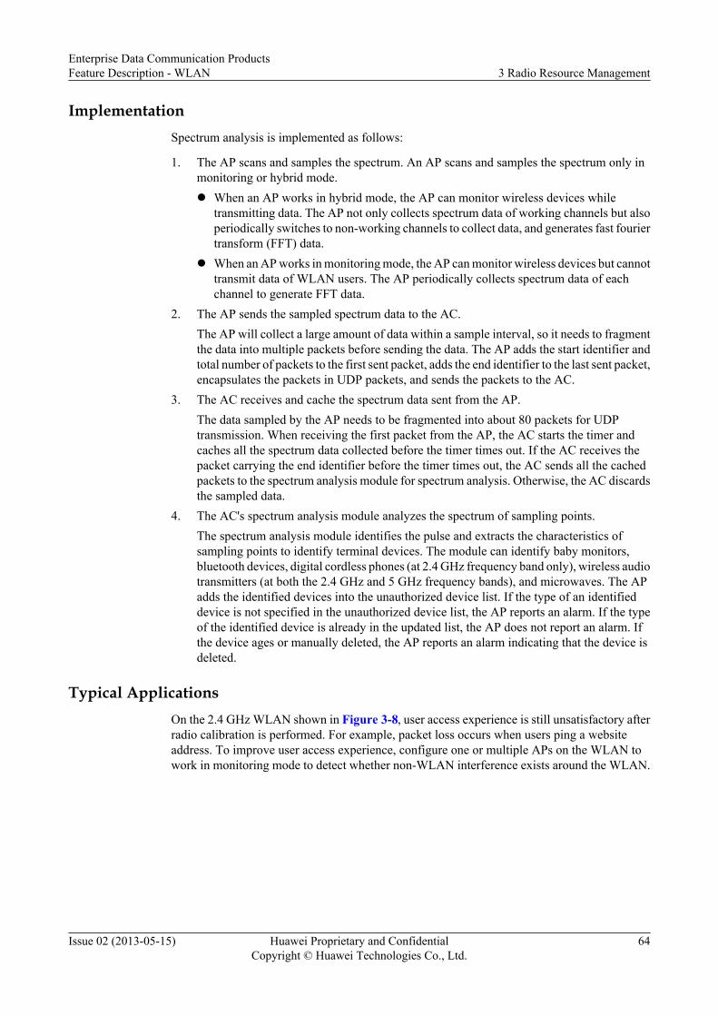
ImplementationSpectrum analysis is implemented as follows:
1. The AP scans and samples the spectrum. An AP scans and samples the spectrum only inmonitoring or hybrid mode.l When an AP works in hybrid mode, the AP can monitor wireless devices while
transmitting data. The AP not only collects spectrum data of working channels but alsoperiodically switches to non-working channels to collect data, and generates fast fouriertransform (FFT) data.
l When an AP works in monitoring mode, the AP can monitor wireless devices but cannottransmit data of WLAN users. The AP periodically collects spectrum data of eachchannel to generate FFT data.
2. The AP sends the sampled spectrum data to the AC.The AP will collect a large amount of data within a sample interval, so it needs to fragmentthe data into multiple packets before sending the data. The AP adds the start identifier andtotal number of packets to the first sent packet, adds the end identifier to the last sent packet,encapsulates the packets in UDP packets, and sends the packets to the AC.
3. The AC receives and cache the spectrum data sent from the AP.The data sampled by the AP needs to be fragmented into about 80 packets for UDPtransmission. When receiving the first packet from the AP, the AC starts the timer andcaches all the spectrum data collected before the timer times out. If the AC receives thepacket carrying the end identifier before the timer times out, the AC sends all the cachedpackets to the spectrum analysis module for spectrum analysis. Otherwise, the AC discardsthe sampled data.
4. The AC's spectrum analysis module analyzes the spectrum of sampling points.The spectrum analysis module identifies the pulse and extracts the characteristics ofsampling points to identify terminal devices. The module can identify baby monitors,bluetooth devices, digital cordless phones (at 2.4 GHz frequency band only), wireless audiotransmitters (at both the 2.4 GHz and 5 GHz frequency bands), and microwaves. The APadds the identified devices into the unauthorized device list. If the type of an identifieddevice is not specified in the unauthorized device list, the AP reports an alarm. If the typeof the identified device is already in the updated list, the AP does not report an alarm. Ifthe device ages or manually deleted, the AP reports an alarm indicating that the device isdeleted.
Typical ApplicationsOn the 2.4 GHz WLAN shown in Figure 3-8, user access experience is still unsatisfactory afterradio calibration is performed. For example, packet loss occurs when users ping a websiteaddress. To improve user access experience, configure one or multiple APs on the WLAN towork in monitoring mode to detect whether non-WLAN interference exists around the WLAN.
Enterprise Data Communication ProductsFeature Description - WLAN 3 Radio Resource Management
Issue 02 (2013-05-15) Huawei Proprietary and ConfidentialCopyright © Huawei Technologies Co., Ltd.
64

Figure 3-8 Spectrum analysis networking
AC (has spectrum analysis enabled)
STA
Monitor AP1
SwitchNMS
Digital cordless phone
Monitor AP2
Monitor AP3
Send sampled data to the AC
3.3 References
The following table lists the reference for this feature.
Document Description Remarks
IEEE 802.11k Radio Resource Measurement ofWireless LANs
-
Enterprise Data Communication ProductsFeature Description - WLAN 3 Radio Resource Management
Issue 02 (2013-05-15) Huawei Proprietary and ConfidentialCopyright © Huawei Technologies Co., Ltd.
65

4 WLAN Reliability
About This Chapter
4.1 Introduction to WLAN Reliability
4.2 Principles
4.3 Applications
4.4 References
Enterprise Data Communication ProductsFeature Description - WLAN 4 WLAN Reliability
Issue 02 (2013-05-15) Huawei Proprietary and ConfidentialCopyright © Huawei Technologies Co., Ltd.
66

4.1 Introduction to WLAN Reliability
As WLAN technologies develop, a lot of users access the Internet through the WLAN. Reliabilityis a major problem to be solved in WLAN transmission. A reliable WLAN can effectively reduceimpact of network faults and service interruption.
4.2 Principles
4.2.1 Non-Stop AP Operation After CAPWAP Link Disconnection
In the direct forwarding scenario that uses the AC+Fit AP architecture, the AP and AC mustestablish a CAWAP tunnel for control packet forwarding before a STA connects to the Internetthrough WLAN. When the CAPWAP tunnel is faulty, the AP cannot forward data packets, onlineusers on the AP are forcibly disconnected from the AP, and new users cannot connect to the AP.These problems affect user experience.
l Service holding upon CAPWAP link disconnectionAfter the service holding function is enabled, the AP can still forward data packets whenthe CAPWAP tunnel is faulty, ensuring nonstop data service transmission in directforwarding mode. This function reduces loss for users and improves service reliability.
Enterprise Data Communication ProductsFeature Description - WLAN 4 WLAN Reliability
Issue 02 (2013-05-15) Huawei Proprietary and ConfidentialCopyright © Huawei Technologies Co., Ltd.
67
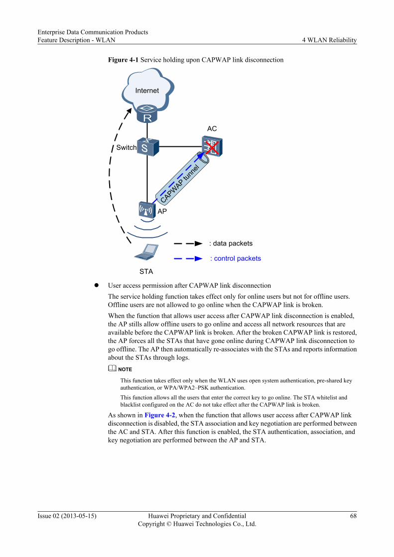
Figure 4-1 Service holding upon CAPWAP link disconnection
STA
AP
Internet
AC
CAPWAP tu
nnel
: data packets
: control packets
Switch
l User access permission after CAPWAP link disconnectionThe service holding function takes effect only for online users but not for offline users.Offline users are not allowed to go online when the CAPWAP link is broken.When the function that allows user access after CAPWAP link disconnection is enabled,the AP stills allow offline users to go online and access all network resources that areavailable before the CAPWAP link is broken. After the broken CAPWAP link is restored,the AP forces all the STAs that have gone online during CAPWAP link disconnection togo offline. The AP then automatically re-associates with the STAs and reports informationabout the STAs through logs.
NOTE
This function takes effect only when the WLAN uses open system authentication, pre-shared keyauthentication, or WPA/WPA2–PSK authentication.
This function allows all the users that enter the correct key to go online. The STA whitelist andblacklist configured on the AC do not take effect after the CAPWAP link is broken.
As shown in Figure 4-2, when the function that allows user access after CAPWAP linkdisconnection is disabled, the STA association and key negotiation are performed betweenthe AC and STA. After this function is enabled, the STA authentication, association, andkey negotiation are performed between the AP and STA.
Enterprise Data Communication ProductsFeature Description - WLAN 4 WLAN Reliability
Issue 02 (2013-05-15) Huawei Proprietary and ConfidentialCopyright © Huawei Technologies Co., Ltd.
68

Figure 4-2 User access permission after CAPWAP link disconnection
STA
AP
LAN
Internet
AC
CAPWAP tu
nnel
Authentication packet exchange before user access permission after CAPWAP link disconnection is disabled
(1)
(1)
(2)
(2) Authentication packet exchange before user access permission after CAPWAP link disconnection is enabled
4.2.2 Dual-Link Backup
In the AC + Fit AP networking, the AC manages and controls WLAN services of users. An ACmay control hundreds of APs and thousands of STAs; therefore, the AC must be highly reliable.If the AC is faulty, the services of all users connected to the AC are interrupted.
As shown in Figure 4-3, an active AC and a standby AC are deployed on the WLAN. The APestablishes tunnels with the two ACs (CAPWAP Tunnel Setup), and periodically exchangesCAPWAP packets with ACs to monitor link status. The active AC controls access of STAs. Ifthe AP detects a fault on the link between AP and active AC, the AP requests the standby ACto trigger an Active/Standby Switchover. The standby AC then becomes the active AC tocontrol access of STAs. After the original active AC is restored, the AP requests the active andstandby ACs to perform Revertive Switchover. The restored AC becomes the active AC again.
Enterprise Data Communication ProductsFeature Description - WLAN 4 WLAN Reliability
Issue 02 (2013-05-15) Huawei Proprietary and ConfidentialCopyright © Huawei Technologies Co., Ltd.
69

Figure 4-3 Dual-link backup networking diagram
Active AC
Standby AC
AP
Switch
STASTA
CAPWAP prim
ary tunnel CAPW
AP b
acku
p tu
nnel
CAPWAP Tunnel Setup1. Setting up the first tunnel
The procedure for setting up the first tunnel is the same as the procedure for setting up aCAPWAP tunnel, except that the active AC needs to be selected in Discovery phase. Onlythe Discovery phase is described in this section. For description of other phases, see"CAPWAP Tunnel Establishment" in 1.2.4 AP Login.
a. After the dual-link backup function is enabled in Discovery phase, the AP sends aDiscovery Request message in unicast or broadcast mode:l If the IP addresses of active and standby ACs have been allocated in static, DHCP,
or DNS mode, the AP sends the Discovery Request message in unicast mode torequest connections with the ACs.
l If no IP addresses are allocated to ACs or there is not response to the unicast packet,the AP sends another Discovery Request message in broadcast mode to discoverthe ACs that can be associated with the AP.
b. As long as the ACs are working properly, they will return Discovery Responsemessages to the AP. The Discovery Response messages contain the dual-link backupflag, priorities, load, and IP addresses of the ACs.
c. After receiving the Discovery Response message, the AP selects an active AC basedon AC priorities, loads, and IP addresses and sets up a CAPWAP primary tunnel withthe active AC. The AP selects the active AC in the following sequence:
a. Compare AC priorities, and select the AC with the smaller priority value as theactive AC.
b. When the AC priorities are the same, compare the loads, that is, the number ofAPs and STAs. Select the AC connecting to fewer APs and STAs as the activeAC.
c. When the loads are the same, compare the ACs' IP addresses, and select the ACwith the smaller IP address as the active AC.
Enterprise Data Communication ProductsFeature Description - WLAN 4 WLAN Reliability
Issue 02 (2013-05-15) Huawei Proprietary and ConfidentialCopyright © Huawei Technologies Co., Ltd.
70

2. Setting up the second tunnel with the other ACTo prevent repeated service configuration delivery, the AP starts to set up the second tunnelonly after the configuration of the first tunnel is complete.
a. The AP sends a Discovery Request message to the other AC in unicast mode.b. The AC returns a Discovery Response message containing the dual-link backup flag,
load, and priority to the AP.c. The AP knows that the dual-link backup function is enabled after receiving the
Discovery Response message, and saves the priority of the AC.
NOTE
If the priority of this AC is higher than the priority of the other AC, the AP performs an active/standby switchover only after the tunnel is set up.
d. The AP sends a Join Request message, notifying the AC that the configurations havebeen delivered. After receiving the Join Request message, the AC sets up a CAPWAPtunnel with the AP but does not deliver configurations to the AP.
e. After the second tunnel is set up, the AP selects the active and standby ACs againbased on the tunnel priorities.
Active/Standby SwitchoverAfter setting up tunnels with the active and standby ACs, the AP sends Echo messages to monitortunnel status. The Echo messages contain the active/standby status of the tunnels. When the APdetects that the primary tunnel fails, it sends an Echo Request message with the active flag tothe standby AC. After receiving the Echo Request message, the standby AC becomes the activeAC, and the AP transfers STA data to this AC.
Revertive SwitchoverThe AP periodically sends Discovery Request messages to check whether the original primarytunnel recovers. If the original primary tunnel recovers, the AP switches STA data back to thistunnel after a delay because this tunnel has a higher priority than the other one. To preventfrequent switchovers caused by network flapping, the AP requests ACs to perform revertiveswitchover after 20 Echo intervals, and then sends STA data to the new active AC.
4.2.3 AC Hot Standby
In dual-link backup, an AP periodically sends Echo packets to the active and standby ACs tomonitor the link status. If the AP does not receive any response from the AC after the Echopackets are sent for the specified number of times, the AP triggers an active/standby switchover.When the AP determines whether to trigger an active/standby switchover, services areinterrupted.
To prevent service interruption in dual-link backup, the AC hot standby mechanism is used toensure that services are seamlessly switched to the standby AC when the active AC fails. Thismechanism ensures non-stop enterprise service transmission and improves reliability.
AC hot standby can be implemented in two modes:
l Hot standby backup (HSB)+Virtual Router Redundancy Protocol (VRRP): An AP canobtain only one AC's IP address. This IP address is the virtual IP address of the active andstandby ACs in a VRRP group. The active and standby ACs are elected among the ACs inthe VRRP group based on the AC priority. The active AC manages and controls all APs
Enterprise Data Communication ProductsFeature Description - WLAN 4 WLAN Reliability
Issue 02 (2013-05-15) Huawei Proprietary and ConfidentialCopyright © Huawei Technologies Co., Ltd.
71

and STAs and periodically sends status information and information to be backed up to thestandby AC through the HSB function in scheduled and real-time backup modes. Theinformation to be backed up includes AC entries, CAPWAP link information, and userinformation. When a fault occurs on the active AC, the standby AC can fast detect the faulton the active AC through the CAPWAP heartbeat mechanism and become the new activeAC in a timely manner. This function ensures nonstop user services.
Figure 4-4 HSB+VRRP networking
Active AC
Internet
Standby AC10.1.1.1/24
10.1.1.2/24
Virtual AC
Switch
Switch
APGateway:10.1.1.10/24IP Address:10.1.1.3/24
APGateway:10.1.1.10/24IP Address:10.1.1.3/24
VRRP Region 1Virtual IP Address:10.1.1.10/24Virtual MAC Address:0000-5e00-0101
Internet
HSB active and standby channels
VRRP group
l HSB+dual-link backup: An AP establishes CAPWAP tunnels with both the active andstandby ACs. The two ACs back up user information through the HSB function. When theactive AC becomes faulty, the AP detects that the active AC fails and switches the standbyCAPWAP tunnel as the new active CAPWAP tunnel.
Enterprise Data Communication ProductsFeature Description - WLAN 4 WLAN Reliability
Issue 02 (2013-05-15) Huawei Proprietary and ConfidentialCopyright © Huawei Technologies Co., Ltd.
72

Figure 4-5 HSB+dual-link backup networking
Active AC Standby AC
AP AP
Aggregation switch
STA
CAPWAP primary linkCAPWAP
bakcup linkSTA STA STA
HSB active and standby channels
Internet
Router
4.3 Applications
4.3.1 Application of Non-Stop AP Operation After CAPWAP LinkDisconnection
As shown in Figure 4-6, to reduce management and maintenance costs, some small- andmedium-sized enterprises deploy the AC at the headquarters to manage the APs and STAs inbranches. In the direct forwarding scenario, after the CAPWAP link between the AP and AC isbroken, online branch users can access local network resources (such as the local servers), andnew branch users can still access the WLAN to obtain network resources.
Enterprise Data Communication ProductsFeature Description - WLAN 4 WLAN Reliability
Issue 02 (2013-05-15) Huawei Proprietary and ConfidentialCopyright © Huawei Technologies Co., Ltd.
73

Figure 4-6 Non-stop AP operation after CAPWAP link disconnection
分支机构Enterprise
branch WAN Enterprise headquarters
AC
NMS
AP
Internet
Online user
Online user
New online user
4.3.2 Application of Dual-Link Backup
1+1 Dual-Link Backup
As shown in Figure 4-7, AC1 and AC2 provide dual links for STAs. AC1 is the active device,serving AP1 and AP2. AC2 is the standby device. When the APs detect that AC1 fails, theCAPWAP tunnels between APs and AC2 become the active tunnels, and AC2 becomes theactive AC. After AC1 recovers, it becomes the active AC or still functions as the standby ACdepending on the configuration.
Figure 4-7 1+1 dual-link backup networking diagram
AC1 AC2
AP1 AP2
Switch
STA
CAPWAP primary tunnelCAPWAP backup tunnelSTA STA STA
Enterprise Data Communication ProductsFeature Description - WLAN 4 WLAN Reliability
Issue 02 (2013-05-15) Huawei Proprietary and ConfidentialCopyright © Huawei Technologies Co., Ltd.
74

N+1 Link Backup
As shown in Figure 4-8, AC1 functions as the active AC for AP1, AC2 functions as the activeAC for AP2, and AC3 functions as the standby AC for AP1 and AP2. When AC1 or AC2 isfaulty, the data from AP1 or AP2 is switched to AC3, ensuring nonstop service transmission.
Figure 4-8 N+1 link backup networking diagram
AC2
AP1 AP2
Switch
STA
CAPWAP primary tunnelCAPWAP backup tunnelSTA STA STA
AC1 AC3
4.3.3 Application of AC Hot StandbyOn a wireless access network, an AC can manage several hundred APs. If the AC becomesfaulty, services of all the APs that associate with the AC are interrupted. To reduce impact ofAC faults, a traditional backup solution deploys two devices on an access node for backup. AnAC on a wireless network usually run Dynamic Host Configuration Protocol (DHCP), networkadmission control (NAC), and wireless local area network (WLAN) services, which require real-time information backup from the active device to the standby device. For example, the activeDHCP device must synchronize user status information to the standby DHCP device in real time.Otherwise, services will be interrupted after link switching.
The AC hot standby function can solve this problem. This function has two modes: HSB+VRRPand HSB+dual-link backup. HSB supports batch backup and real-time backup between the twoaccess devices. When the active device fails, service traffic is immediately switched to thestandby device without interrupting services. This improves connection availability. Dual-linkbackup or VRRP can fast detect whether the active AC is faulty so that the standby AC canbecome the new active AC in a timely manner. This function ensures user service continuity.
Enterprise Data Communication ProductsFeature Description - WLAN 4 WLAN Reliability
Issue 02 (2013-05-15) Huawei Proprietary and ConfidentialCopyright © Huawei Technologies Co., Ltd.
75

HSB+Dual-Link BackupIn Figure 4-9, an enterprise deploys two ACs: AC1 (active AC) and AC2 (standby AC). AP1associates with AC1, and AP2 associates with AC2. NAC and WLAN services are deployed onAC1 and AC2. AC1 and AC2 are bound to the same HSB tunnel.
Load balancing can be implemented on AC1 and AC2 to fully use network resources. For AP1,AC1 is the active device and AC2 is the standby device. All service traffic of AP1 is forwardedby AC1. For AP2, AC2 is the active device and AC1 is the standby device. All service trafficof AP2 is forwarded by AC2. Traffic of AP1 and AP2 is load balanced between the two ACs,improving link efficiency.
Figure 4-9 HSB+dual-link backup networking
AC1
STA1AP1
AP2
Switch
AC2
Network
STA2
AP1's master link
AP1's backup link
AP2's master link
AP2's backup link
HSB+VRRPIn Figure 4-10, an enterprise deploys two ACs: AC1 (active AC) and AC2 (standby AC). AP1associates with AC1, and AP2 associates with AC2. DHCP, NAC, and WLAN services aredeployed on AC1 and AC2. AC1 and AC2 are bound to an HSB group that works in active/standby mode.
When AC1 fails, AC2 immediately takes over the DHCP, NAC, and WLAN services becauseit has backed up all the required information from AC1. Services are not interrupted after thelink switching.
Enterprise Data Communication ProductsFeature Description - WLAN 4 WLAN Reliability
Issue 02 (2013-05-15) Huawei Proprietary and ConfidentialCopyright © Huawei Technologies Co., Ltd.
76

Figure 4-10 HSB+VRRP networking
AC1 Master
STA1AP1
AP2
Switch
AC2 Backup
Network
STA2
4.4 References
None
Enterprise Data Communication ProductsFeature Description - WLAN 4 WLAN Reliability
Issue 02 (2013-05-15) Huawei Proprietary and ConfidentialCopyright © Huawei Technologies Co., Ltd.
77

5 WLAN Roaming
About This Chapter
5.1 Introduction to WLAN Roaming
5.2 Principles
5.3 References
Enterprise Data Communication ProductsFeature Description - WLAN 5 WLAN Roaming
Issue 02 (2013-05-15) Huawei Proprietary and ConfidentialCopyright © Huawei Technologies Co., Ltd.
78

5.1 Introduction to WLAN Roaming
DefinitionWLAN roaming allows a STA to move from an AP to another AP in the same ESS on a WLANnetwork with nonstop service transmission. In Figure 5-1, the STA moves from AP1 to AP2.
Figure 5-1 WLAN roaming networking
Roaming
AP2AP1
SSID: Huawei
AC
SSID: HuaweiChannel 6Channel 1
Internet
STA STA
WLAN roaming includes roaming between APs in the same service VLAN and roaming betweenAPs in different service VLANs:l Roaming between APs in the same service VLAN: APs before and after STA roaming
belong to the same service VLAN.l Roaming between APs in different service VLANs: APs before and after STA roaming
belong to different service VLANs. To prevent services of a user from being interruptedduring WLAN roaming, ensure that the service VLAN of the user remains unchanged afterthe user roams between two APs.
WLAN roaming is classified into fast roaming and non-fast roaming based on the security policyused by STAs. As shown in Table 5-1, fast roaming can be implemented only when the securitypolicy is WPA2-802.1x and STAs support fast roaming. When the security policy is notWPA2-802.1x, non-fast roaming is implemented regardless of whether STAs support fastroaming. When the security policy is WPA2-802.1x but STAs do not support fast roaming, non-fast roaming is implemented.
Enterprise Data Communication ProductsFeature Description - WLAN 5 WLAN Roaming
Issue 02 (2013-05-15) Huawei Proprietary and ConfidentialCopyright © Huawei Technologies Co., Ltd.
79

Table 5-1 Fast roaming and non-fast roaming
Security Policy Whether AccessAuthentication IsRequired Again
Whether STAsSupport FastRoaming
Roaming Mode
WEP open systemauthentication
No N/A Non-fast roaming
WEP shared keyauthentication
No N/A Non-fast roaming
WPA/WPA2-PSK Yes N/A Non-fast roaming
WPA-802.1x Yes N/A Non-fast roaming
WPA2-802.1x Yes No Non-fast roaming
WPA2-802.1x No Yes Fast roaming
PurposeThe biggest advantage of WLAN networks is that a STA can move within a WLAN networkregardless of physical media locations. WLAN roaming ensures that a STA moves within aWLAN network without interrupting services. An ESS includes multiple APs. When a STAmoves from an AP to another AP, WLAN roaming ensures seamless transition of STA servicesbetween APs.
WLAN roaming has the following advantages:l Prevents packet loss or service interruption caused by long-term authentication.
If a STA needs to be authenticated before accessing the Internet, the authentication process(for example, 802.1x authentication) may take a long period of time. Fast roaming preventsSTA re-authentication, ensuring nonstop user service transmission.
l Ensures that users' IP addresses remain unchanged.Application protocol packets are transmitted using IP addresses and TCP/UDP connections.STAs' IP addresses must remain unchanged after WLAN roaming so that the TCP/UDPconnections established for the STAs are not interrupted.
5.2 Principles
5.2.1 Roaming Between APs in the Same Service VLAN
Roaming between APs in the same service VLAN allows a STA to move between two APs thatconnect to the same AC and belong to the same service VLAN without service interruption, asshown in Figure 5-2.
Enterprise Data Communication ProductsFeature Description - WLAN 5 WLAN Roaming
Issue 02 (2013-05-15) Huawei Proprietary and ConfidentialCopyright © Huawei Technologies Co., Ltd.
80

Figure 5-2 Roaming between APs in the same service VLAN
Roaming
AP2AP1
SSID: Huawei
AC
SSID: HuaweiChannel 6Channel 1
Internet
STA STA
VLAN10 VLAN10
Roaming between APs in the same service VLAN is classified into fast roaming and non-fastroaming.
Non-Fast RoamingNon-fast roaming technology is used when a STA uses a non-WPA2-802.1x security policy. Ifa STA uses WPA2-802.1x but does not support fast roaming, the STA still needs to complete802.1x authentication before roaming between two APs.
NOTE
STA needs to roam between two APs, the APs must have the same SSID (for example, the SSIDs in Figure5-2 are Huawei) and security policy profile.
In Figure 5-2, the STA accesses the Internet through AP1. The STA needs to roam from AP1to AP2, and the STA roaming process is as follows:
1. The STA sends a Probe Request frame on each channel. After receiving the Probe Requestframe, APs send Probe Response frames to the STA. For example, after AP2 receives theProbe Request frame on channel 6 (a channel used by AP2), AP2 sends a Probe Responseframe on channel 6 to the STA. When the STA receives Probe Response frames from APs,the STA selects an AP to associate with according to the signal strength and quality. Assumethat the STA selects AP2 to associate with as shown in Figure 5-2.
2. The STA sends a Re-authentication Request packet on channel 6 to AP2. After the STA isauthenticated by AP2, AP2 sends a Re-authentication Response packet to the STA.
3. The STA sends a Re-association Request packet to AP2, which then sends the packet tothe AC. The AC sends a Re-association Response packet, allowing the STA to re-associatewith AP2.
4. The STA re-associates with AP2 and then disassociates from AP1. The STA sends aDisassociation frame to AP1 on channel 1 (a channel used by AP1) to disassociate fromAP1.
Enterprise Data Communication ProductsFeature Description - WLAN 5 WLAN Roaming
Issue 02 (2013-05-15) Huawei Proprietary and ConfidentialCopyright © Huawei Technologies Co., Ltd.
81

l If the STA uses the WEP security policy, the STA roaming process is complete.
l If the STA uses the WPA/WPA2-PSK security policy, the STA needs to perform accessauthentication and key negotiation again. For details about key negotiation, see KeyNegotiation in 2.3.1.2 WPA/WPA2.
l If the STA uses the WPA/WPA2-802.1x security policy, the STA needs to performaccess authentication and key negotiation again. For details, see 2.3.1.2 WPA/WPA2.
Fast Roaming
The roaming switchover time is a key factor that affects WLAN service experience duringroaming. When a user uses the WEP or WPA/WPA2-PSK security policy, the roamingswitchover time is less than 100 ms, so the user does not detect service interruption duringroaming. When the user uses the WPA2-802.1x security policy, the roaming switchover time ismore than 100 ms because the user needs to perform 802.1x authentication and key negotiationagain. The user then detects service interruption during roaming.
When the user uses the WPA2-802.1x security policy and supports fast roaming, the user doesnot need to perform 802.1x authentication again during roaming and only needs to perform keynegotiation. In this case, fast roaming reduces the roaming delay and improves the WLANservice experience.
Fast roaming is implemented using pairwise master key (PMK) caching. In Figure 5-2, the fastroaming process is as follows:
1. The STA accesses the Internet through AP1 for the first time. When the STA isauthenticated by the AC and a PMK is generated, the STA and AC save the PMKinformation. Each PMK has a PMK-ID, which is calculated based on the PMK, SSID, STAMAC address, and BSSID.
2. During roaming, the STA sends AP2 a Re-association Request packet that carries the PMK-ID.
3. AP2 receives the Re-association Request packet and then notifies the AC that the STAneeds to roam from AP1 to AP2.
4. The AC searches the PMK caching table for the PMK of the STA according to the PMK-ID carried in the Re-association Request packet. If the AC finds a matching PMK, the ACconsiders that 802.1x authentication has been performed on the STA and uses the cachedPMK for key negotiation.
5.2.2 Roaming Between APs in Different Service VLANs
Like wired LANs, to prevent broadcast storms, enterprise users on enterprise WLANs areassigned different VLANs according to their floors and departments. If APs deployed at differentfloors belong to different VLANs, services of a user are interrupted when the user roams betweentwo APs at different floors. Inter-VLAN Layer 3 roaming prevents service interruption in thiscase, improving WLAN service experience.
In roaming between APs in different service VLANs, APs before and after STA roaming belongto different service VLANs. To prevent services of a user from being interrupted during WLANroaming, ensure that the service VLAN of the user remains unchanged after the user roamsbetween two APs.
Enterprise Data Communication ProductsFeature Description - WLAN 5 WLAN Roaming
Issue 02 (2013-05-15) Huawei Proprietary and ConfidentialCopyright © Huawei Technologies Co., Ltd.
82

Figure 5-3 Roaming between APs in different service VLANs
Roaming
AP2AP1
SSID: Huawei
AC
SSID: HuaweiChannel 6Channel 1
Internet
STA STA
VLAN10 VLAN20
You can classify roaming between APs in different service VLANs into fast roaming and non-fast roaming according to whether STAs support fast roaming. For the implementation principlesof fast roaming and non-fast roaming, see 5.2.1 Roaming Between APs in the Same ServiceVLAN. Figure 5-3 describes how to keep the service VLAN of a STA unchanged duringroaming of the STA.
Figure 5-3 shows the process of roaming between APs in different service VLANs:
1. When the STA accesses the Internet through AP1 in VLAN 10, the AC determines that theSTA accesses the Internet for the first time and creates and saves service data of the STA,including the service VLAN of the AP, AP ID, radio, and VAP information.
2. The STA moves from AP1 to AP2 in VLAN 20 and re-associates with the AC throughAP2. The AC determines that the STA is roaming based on the user information, updatesthe service database, and updates the AP ID, radio, and VAP information to be consistentwith AP2 information without changing the VLAN ID. The VLAN is still the service VLANto which AP1 belongs.
3. The STA disassociates from AP1. Although the STA resides on different subnets afterroaming between two APs, the AC still considers that the STA accesses the Internet fromthe first VLAN (VLAN 10), allowing the STA to retain its IP address to ensure nonstopservice interruption.
5.2.3 Key Negotiation Between STA and AP
If a STA uses the WPA/WPA2 security policy, during roaming, the STA needs to perform keynegotiation with an AC again. If the STA performs key negotiation with an AP, the roamingswitchover time is reduced, implementing rapid roaming, as shown in Figure 5-4.
Enterprise Data Communication ProductsFeature Description - WLAN 5 WLAN Roaming
Issue 02 (2013-05-15) Huawei Proprietary and ConfidentialCopyright © Huawei Technologies Co., Ltd.
83

Figure 5-4 Key negotiation between STA and AP
Key negotiation (four-way handshake)
Send the key result to the AC
Key negotiation is shielded
STA AP AC
Key negotiation (four-way handshake)
STA AP AC
Key negotiation between STA and AP
In key negotiation between a STA and an AP, the STA sends a Re-association Request packetto the AP:l If fast roaming is used, the AP sends the PMK-ID of the STA to the AC. The AC finds the
PMK of the STA based on the PMK-ID and sends the PMK information to the AP.Subsequently, key negotiation is performed between the STA and AP. After the negotiationsucceeds, the AP sends the key result to the AC.
l If non-fast roaming is used, the AC sends the generated PMK to the AP after the STA isre-authenticated through the AP. Subsequently, key negotiation is performed between theSTA and AP. After the negotiation succeeds, the AP sends the key result to the AC.
5.3 References
The following table lists the references.
Document Description Remarks
IEEE 802.11r WLAN roaming standard -
Enterprise Data Communication ProductsFeature Description - WLAN 5 WLAN Roaming
Issue 02 (2013-05-15) Huawei Proprietary and ConfidentialCopyright © Huawei Technologies Co., Ltd.
84

6 WLAN QoS
About This Chapter
6.1 Introduction to WLAN QoS
6.2 Principles
6.3 Applications
6.4 References
Enterprise Data Communication ProductsFeature Description - WLAN 6 WLAN QoS
Issue 02 (2013-05-15) Huawei Proprietary and ConfidentialCopyright © Huawei Technologies Co., Ltd.
85

6.1 Introduction to WLAN QoS
Definition
WLAN Quality of Service (QoS) provides differentiated service for wireless users to satisfytheir traffic requirements. As shown in Figure 6-1, WLAN QoS has the following functions:
1. High-efficiency use of wireless channels: The Wi-Fi multimedia (WMM) standard enablesthe high-priority users to preempt wireless channels.
2. Efficient bandwidth use: Priority mapping preferentially transmits the data of high-priorityusers.
3. Network congestion prevention: Traffic policing limits users' transmission rate, preventingnetwork congestion.
Figure 6-1 WLAN QoS networking
STA AP AC
InternetCAPWAP tunnel
1. WMM: High priority packets preempt channel
2. Priority mapping between AP and AC
3. Monitor traffic from STA and VAP
Purpose
Applications have differentiated network requirements. The traditional WLAN is mainly usedto transmit data due to its low transmission rate. With development of new WLAN technologies,WLANs have been applied to media, financial, education, and enterprise networks. In additionto data traffic, WLANs can also transmit delay-sensitive multimedia data, such as voice andvideo. By enforcing QoS policies on a WLAN, the network administrator can properly plan andassign network resources based on service characteristics. The WLAN then providesdifferentiated access services for applications, meeting customer requirements and improvingnetwork use efficiency.
6.2 Principles
Enterprise Data Communication ProductsFeature Description - WLAN 6 WLAN QoS
Issue 02 (2013-05-15) Huawei Proprietary and ConfidentialCopyright © Huawei Technologies Co., Ltd.
86

6.2.1 WMM
BackgroundBefore learning WMM, you must understand 802.11 link layer transport mechanism.
802.11 MAC layer uses the coordination function to determine the data transmitting andreceiving methods used between STAs in a BSS. 802.11 MAC layer consists of two sub-layers:l Distributed Coordination Function (DCF): uses the CSMA/CA mechanism. STAs compete
channels to obtain the authority to transmit data frames.l Point Coordination Function (PCF): uses centralized control to authorize STAs to transmit
data frames in turn. This method prevents conflict.
NOTE
In 802.11 protocol, DCF is mandatory, and PCF is optional.
Figure 6-2 shows how CSMA/CA is implemented.
Figure 6-2 CSMA/CA working mechanism
STA A
STA B
Idle channel
DIFS
Frame
Other STAs
ACK
NAV (busy channel)
STA A sends data to STA B
SIFS
DIFS
CW
Frame
Wait
1. Before sending data to STA B, STA A detects channel status. When detecting an idlechannel, STA A sends a data frame after Distributed Inter-Frame Space (DIFS) times outand waits for a response from STA B. The data frame contains NAV information. Afterreceiving the data frame, STA B updates the NAV information, indicating that the channelis busy and data transmission will be delayed.
NOTE
According to 802.11 protocol, the receiver must return an ACK frame each time it receives a dataframe.
2. STA B receives the data frame, waits until Short Interframe Space (SIFS) times out, andsends an ACK frame to STA A. After the ACK frame is transmitted, the channel becomesidle. After the DIFS times out, the STAs use the exponential backoff algorithm to competechannels. The STA of which the backoff counter is first reduced to 0 starts to send dataframe.
Enterprise Data Communication ProductsFeature Description - WLAN 6 WLAN QoS
Issue 02 (2013-05-15) Huawei Proprietary and ConfidentialCopyright © Huawei Technologies Co., Ltd.
87
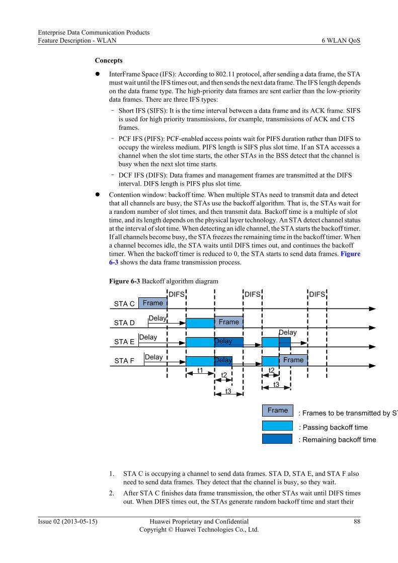
Concepts
l InterFrame Space (IFS): According to 802.11 protocol, after sending a data frame, the STAmust wait until the IFS times out, and then sends the next data frame. The IFS length dependson the data frame type. The high-priority data frames are sent earlier than the low-prioritydata frames. There are three IFS types:– Short IFS (SIFS): It is the time interval between a data frame and its ACK frame. SIFS
is used for high priority transmissions, for example, transmissions of ACK and CTSframes.
– PCF IFS (PIFS): PCF-enabled access points wait for PIFS duration rather than DIFS tooccupy the wireless medium. PIFS length is SIFS plus slot time. If an STA accesses achannel when the slot time starts, the other STAs in the BSS detect that the channel isbusy when the next slot time starts.
– DCF IFS (DIFS): Data frames and management frames are transmitted at the DIFSinterval. DIFS length is PIFS plus slot time.
l Contention window: backoff time. When multiple STAs need to transmit data and detectthat all channels are busy, the STAs use the backoff algorithm. That is, the STAs wait fora random number of slot times, and then transmit data. Backoff time is a multiple of slottime, and its length depends on the physical layer technology. An STA detect channel statusat the interval of slot time. When detecting an idle channel, the STA starts the backoff timer.If all channels become busy, the STA freezes the remaining time in the backoff timer. Whena channel becomes idle, the STA waits until DIFS times out, and continues the backofftimer. When the backoff timer is reduced to 0, the STA starts to send data frames. Figure6-3 shows the data frame transmission process.
Figure 6-3 Backoff algorithm diagram
STA C
STA D
FrameDIFS
Delay Frame
DIFS
STA EDelay Delay
STA F Delay Delay Frame
DIFS
Delay
Frame : Frames to be transmitted by STA
: Passing backoff time
: Remaining backoff time
t1t2
t3
t2
t3
1. STA C is occupying a channel to send data frames. STA D, STA E, and STA F alsoneed to send data frames. They detect that the channel is busy, so they wait.
2. After STA C finishes data frame transmission, the other STAs wait until DIFS timesout. When DIFS times out, the STAs generate random backoff time and start their
Enterprise Data Communication ProductsFeature Description - WLAN 6 WLAN QoS
Issue 02 (2013-05-15) Huawei Proprietary and ConfidentialCopyright © Huawei Technologies Co., Ltd.
88

backoff timers. For example, the backoff time of STA D is t1, the backoff time of STAE is t1+t3, and the backoff time of STA F is t1+t2.
3. When t1 times out, the backoff timer of STA D is reduced to 0. STA D starts to senddata frames.
4. STA E and STA F detect that the channel is busy, so they freeze their backoff timersand wait. After STA D completes data transmission, STA E and STA F wait untilDIFS times out, and continue their backoff timers.
5. When t2 times out, the backoff timer of STA F is reduced to 0. STA F starts to senddata frames.
PrinciplesChannel competition is based on DCF. To all STAs, the DIFS is fixed and backoff time israndom; therefore, all the STAs fairly compete channels. WMM is an enhancement to 802.11protocol. It makes channel competition unfair.
l EDCA parametersWMM defines a set of Enhanced Distributed Channel Access (EDCA) parameters, whichdistinguish high priority packets and enables the high priority packets to preempt channels.WMM classifies data packets into four access categories (ACs). Table 6-1 shows themappings between ACs and 802.11 user preferences (UPs). A large UP value indicates ahigh priority.
Table 6-1 Mappings between ACs and UPs
UP AC
7 AC_VO (Voice)
6
5 AC_VI (Video)
4
3 AC_BE (Best Effort)
0
2 AC_BK (Background)
1
Each AC queue defines a set of EDCA parameters, which determine the capability ofoccupying channels. These parameters ensure that the high priority ACs have higherprobability to preempt channels than low priority ACs.Table 6-2 describes the EDCA parameters.
Enterprise Data Communication ProductsFeature Description - WLAN 6 WLAN QoS
Issue 02 (2013-05-15) Huawei Proprietary and ConfidentialCopyright © Huawei Technologies Co., Ltd.
89

Table 6-2 EDCA parameter description
Parameter Meaning
Arbitration Inter Frame SpacingNumber (AIFSN)
The DIFS has a fixed value. WMM providesdifferent DIFS values for different ACs. A largeAIFSN value means that the STA must wait for along time and has a low priority.
Exponent form of CWmin(ECWmin) and Exponent form ofCWmax (ECWmax)
ECWmin specifies the minimum backoff time, andECWmax specifies the maximum backoff time.They determine the average backoff time. LargeECWmin and ECWmax values mean that theaverage backoff time for the STA is long and theSTA priority is low.
Transmission Opportunity Limit(TXOPLimit)
After preempting a channel, the STA can occupy thechannel within the period of TXOPLimit. A largeTXOPLimit value means that the STA can occupythe channel for a long time. If the TXOPLimit valueis 0, the STA can send only one data frame everytime it preempts a channel.
As shown in Figure 6-4, the AIFSN (AIFSN[6]) and backoff time of voice packets areshorter than those of Best Effort packets. When both voice packets and Best Effort packetsneed to be sent, voice packets can preempt the channel.
Figure 6-4 WMM working mechanism
Voice
Frame
AIFSN[6]
Delay
Best Effort
Delay
Frame : Frames to be transmitted by STA
: Backoff time
: Remaining backoff time
AIFSN[0]
FrameDelay
AIFSN[6]AIFSN[0]
FrameDelay
l ACK policy
WMM defines two ACK policies: normal ACK and no ACK.
Enterprise Data Communication ProductsFeature Description - WLAN 6 WLAN QoS
Issue 02 (2013-05-15) Huawei Proprietary and ConfidentialCopyright © Huawei Technologies Co., Ltd.
90

– Normal ACK: The receiver must return an ACK frame each time it receives a unicastpacket.
– No ACK: The receiver does not need to return ACK frames after receiving packets.This mode is applicable to the environment that has high communication quality andlittle interference.
NOTE
l The ACK policy is only valid to APs.
l If communication quality is poor, the no ACK policy may cause more packets to be lose.
6.2.2 Priority Mapping
Packets of different types have different priorities. For example, the 802.11 packets sent by STAscarry user preferences, VLAN packets on the wired networks carry 802.1p priorities, and IPpackets carry precedence values or DSCP priorities. Priority mapping must be configured onnetwork devices to retain priorities of packets when the packets traverse different networks.
Figure 6-5 Priority mapping diagram
802.11 frame 802.3 frame
CAPWAP encapsulation
802.11 frame 802.3 frame
CAPWAP encapsulation
STA AP AC
Internet
UP 802.1p
802.1p802.1p
UP
1
2
3
Precedence Precedence
802.1p802.1p Precedence Precedence
Precedence802.1p
CAPWAP tunnel
As shown in Figure 6-5:
1. After receiving the upstream 802.11 frames from the STA, the AP maps the user preferencesto the 802.1p priorities.
2. In the upstream direction, if tunnel forwarding mode is used, the 802.1p priorities orprecedence values must be mapped to tunnel priorities.
3. The AC forwards the 802.3 frames received from the Internet to the AP directly or througha tunnel. After receiving the downstream 802.3 frames, the AP maps the 802.1p prioritiesor precedence values to the user preference.
Enterprise Data Communication ProductsFeature Description - WLAN 6 WLAN QoS
Issue 02 (2013-05-15) Huawei Proprietary and ConfidentialCopyright © Huawei Technologies Co., Ltd.
91

Precedence fieldAs defined in RFC 791, the 8-bit ToS field in an IP packet header contains a 3-bit IP precedencefield. Figure 6-6 shows the Precedence field in an IP packet. Bits 0 to 2 constitute the Precedencefield, representing precedence values 7, 6, 5, 4, 3, 2, 1 and 0 in descending order of priority.
Figure 6-6 IP Precedence field
0 7654321
VersionLength
ToS1 Byte Len ID Flags/
offset TTL Proto FCS IP-SA IP-DA Data
IP Precedence
Precedence D T R C
802.1p FieldLayer 2 devices exchange ethernet frames. As defined in IEEE 802.1Q, the PRI field (802.1pfield) in the ethernet frame header identifies the Class of Service (CoS) requirement. Figure6-7 shows the PRI field in ethernet frames.
Figure 6-7 802.1p field in the Ethernet frame
Source address
802.1Q Tag
Length/Type FCSDataDestination
address
3bits
TPID PRI CFI VLAN ID
16bits 1bit 12bits
The 802.1Q header contains a 3-bit PRI field, representing eight service priorities 7, 6, 5, 4, 3,2, 1 and 0 in descending order of priority.
6.2.3 Traffic Policing
Traffic policing discards excess traffic to limit the traffic within a specified range and to protectnetwork resources as well as the enterprise benefits.
Traffic policing is implemented using the token bucket.
A token bucket has specified capacity to store tokens. The system places tokens into a tokenbucket at the configured rate. If the token bucket is full, excess tokens overflow and no token isadded.
Enterprise Data Communication ProductsFeature Description - WLAN 6 WLAN QoS
Issue 02 (2013-05-15) Huawei Proprietary and ConfidentialCopyright © Huawei Technologies Co., Ltd.
92

When assessing traffic, a token bucket forwards packets based on the number of tokens in thetoken bucket. If there are enough tokens in the token bucket for forwarding packets, the trafficrate is within the rate limit. Otherwise, the traffic rate is not within the rate limit.
The working mechanisms of token buckets include single rate single bucket, single rate dualbucket, and dual rate dual bucket.
Single Bucket at a Single Rate
Figure 6-8 Single bucket at a single rate
Tokens
CIR
Packets(B)
CBS
B≦Tc
YES
NO
Conform
Violate
As shown in Figure 6-8, the bucket is called bucket C. Tc indicates the number of tokens inbucket C. A single bucket at a single rate uses the following parameters:
l Committed information rate (CIR): indicates the rate at which tokens are put into bucketC, that is, average traffic rate permitted by bucket C.
l Committed burst size (CBS): indicates the capacity of bucket C, that is, maximum volumeof burst traffic allowed by bucket C each time.
The system places tokens into the bucket at the CIR. If Tc is smaller than the CBS, Tc increases.If Tc is larger than or equal to the CBS, Tc remains unchanged.
B indicates the size of an arriving packet:
l If B is smaller than or equal to Tc, the packet is colored green, and Tc decreases by B.
l If B is larger than Tc, the packet is colored red, and Tc remains unchanged.
Enterprise Data Communication ProductsFeature Description - WLAN 6 WLAN QoS
Issue 02 (2013-05-15) Huawei Proprietary and ConfidentialCopyright © Huawei Technologies Co., Ltd.
93

Dual Buckets at a Single RateDual buckets at a single rate use A Single Rate Three Color Marker (srTCM) defined in RFC2697 to assess traffic and mark packets in green, yellow, and red based on the assessment result.
Figure 6-9 Dual buckets at a single rate
Tokens
CIR
Packets(B)
CBS
B≦Tc
YES
NO
Conform
B≦Te
Overflow
EBS
YES
NO
Exceed Violate
As shown in Figure 6-9, the two buckets are called bucket C and bucket E. Tc indicates thenumber of tokens in bucket C, and Te indicates the number of tokens in bucket E. Dual bucketsat a single rate use the following parameters:l CIR: indicates the rate at which tokens are put into bucket C, that is, average traffic rate
permitted by bucket C.l CBS: indicates the capacity of bucket C, that is, maximum volume of burst traffic allowed
by bucket C each time.l Excess burst size (EBS): indicates the capacity of bucket E, that is, maximum volume of
excess burst traffic allowed by bucket E each time.
The system places tokens into the bucket at the CIR:l If Tc is smaller than the CBS, Tc increases.l If Tc is equal to the CBS and Te is smaller than the EBS, Te increases.l If Tc is equal to the CBS and Te is equal to the EBS, Tc and Te do not increase.
B indicates the size of an arriving packet:l If B is smaller than or equal to Tc, the packet is colored green, and Tc decreases by B.
Enterprise Data Communication ProductsFeature Description - WLAN 6 WLAN QoS
Issue 02 (2013-05-15) Huawei Proprietary and ConfidentialCopyright © Huawei Technologies Co., Ltd.
94

l If B is larger than Tc and smaller than or equal to Te, the packet is colored yellow and Tedecreases by B.
l If B is larger than Te, the packet is colored red, and Tc and Te remain unchanged.
Dual Buckets at Dual RatesDual buckets at dual rates use A Two Rate Three Color Marker (trTCM) defined in RFC 2698to assess traffic and mark packets in green, yellow, and red based on the assessment result.
Figure 6-10 Dual buckets at dual rates
Tokens
PIR
Packets(B)
PBS
B>Tp
YES
NO
Violate
B>Tc
CBS
YES
NO
Exceed Conform
Tokens
CIR
As shown in Figure 6-10, the two buckets are called bucket P and bucket C. Tp indicates thenumber of tokens in bucket P, and Tc indicates the number of tokens in bucket C. Dual bucketsat dual rates use the following parameters:l Peak information rate (PIR): indicates the rate at which tokens are put into bucket P, that
is, average traffic rate permitted by bucket P. The PIR must be greater than the CIR.l CIR: indicates the rate at which tokens are put into bucket C, that is, average traffic rate
permitted by bucket C.l Peak burst size (PBS): indicates the capacity of bucket P, that is, maximum volume of burst
traffic allowed by bucket P each time.l CBS: indicates the capacity of bucket C, that is, maximum volume of burst traffic allowed
by bucket C each time.
The system places tokens into bucket P at the PIR and places tokens into bucket C at the CIR:
Enterprise Data Communication ProductsFeature Description - WLAN 6 WLAN QoS
Issue 02 (2013-05-15) Huawei Proprietary and ConfidentialCopyright © Huawei Technologies Co., Ltd.
95

l If Tp is smaller than the PBS, Tp increases. If Tp is larger than or equal to the PBS, Tpremains unchanged.
l If Tc is smaller than the CBS, Tc increases. If Tc is larger than or equal to the CBS, Tpremains unchanged.
B indicates the size of an arriving packet:
l If B is larger than Tp, the packet is colored red.
l If B is larger than Tc and smaller than or equal to Tp, the packet is colored yellow and Tpdecreases by B.
l If B is smaller than or equal to Tc, the packet is colored green, and Tp and Tc decrease byB.
Implementation of Traffic Policing
Figure 6-11 Traffic policing components
Meter MarkerPacket Stream
Result
Action Packet Stream
As shown in Figure 6-11, traffic policing involves the following components:
l Meter: measures the network traffic using the token bucket mechanism and sends themeasurement result to the marker.
l Marker: colors packets in green, yellow, or red based on the measurement result receivedfrom the meter.
l Action: performs actions based on packet coloring results received from the marker. Thefollowing actions are defined:
– Pass: forwards the packets that meet network requirements.
– Remark + pass: changes the local priorities of packets and forwards them.
– Discard: drops the packets that do not meet network requirements.By default, green and yellow packets are forwarded, and red packets are discarded.
If the rate of a type of traffic exceeds the threshold, the device reduces the packet priority andthen forwards the packets or directly discards the packets based on traffic policing configuration.By default, the packets are discarded.
6.3 Applications
As shown in Figure 6-12, network bandwidth is limited. The device needs to providedifferentiated services for services, for example, reducing jitter and latency of voice packets andguaranteeing bandwidth for key services.
Enterprise Data Communication ProductsFeature Description - WLAN 6 WLAN QoS
Issue 02 (2013-05-15) Huawei Proprietary and ConfidentialCopyright © Huawei Technologies Co., Ltd.
96

Figure 6-12 WLAN QoS networking diagram
Internet
Video conference
HTTP browse
HTTP browse
Voice chat
AP1
AP2
AC
l By using WMM, voice or video data can preempt wireless channels.l By using priority mapping, high priority data is transmitted first.l By using traffic policing, user data rate is limited and network congestion is prevented.
6.4 References
The following table lists the references.
Document Description Remarks
IEEE 802.11e Support on QoS -
Enterprise Data Communication ProductsFeature Description - WLAN 6 WLAN QoS
Issue 02 (2013-05-15) Huawei Proprietary and ConfidentialCopyright © Huawei Technologies Co., Ltd.
97

7 WLAN WDS
About This Chapter
7.1 Introduction to WDS
7.2 Principles
7.3 Applications
7.4 References
Enterprise Data Communication ProductsFeature Description - WLAN 7 WLAN WDS
Issue 02 (2013-05-15) Huawei Proprietary and ConfidentialCopyright © Huawei Technologies Co., Ltd.
98

7.1 Introduction to WDS
Definition
A wireless distribution system (WDS) connects two or more wired or wireless LANs wirelesslyto establish a large network.
Purpose
On a traditional WLAN, APs exchange data with STAs using wireless channels and connect toa wired network through uplinks. To expand the coverage area of a wireless network, APs needto be connected by switches. This deployment requires high costs and takes a long time. In someplaces, such as subways, tunnels, and docks, it is difficult to connect APs to the Internet throughwired links. WDS technology can connect APs wirelessly in these places, which reduces networkdeployment costs, makes the network easy to expand, and allows flexible networking.
7.2 Principles
WDS Concepts
Figure 7-1 WDS networking
STA
STA
AP3(leaf)
AP2(middle)
AP1(root)
STALAN
WDS network
Internet
: Management wireless virtual link: Service wireless virtual link
STA VAP: VAP13
VAP0
AP VAP:VAP12
AC
Root wired interface
Endpointwired interface
PC
Switch
Enterprise Data Communication ProductsFeature Description - WLAN 7 WLAN WDS
Issue 02 (2013-05-15) Huawei Proprietary and ConfidentialCopyright © Huawei Technologies Co., Ltd.
99

l Service VAP: On a traditional WLAN, an AP is a physical entity that provides WLANservices to STAs. A service virtual access point (VAP) is a logical entity that providesaccess service for users. Multiple VAPs can be created on an AP to provide access servicefor multiple user groups. As shown in Figure 7-1, VAP0 created on AP3 is a service VAP.
NOTEWhen you create service VAPs, the system allocates VAPs to service sets in sequence, starting fromVAP0 by default. That is, the system allocates VAP0 to the first service set and VAP1 to the secondservice set.
l Bridge VAP: On a WDS network, an AP is a physical entity that provides WDS servicefor neighboring devices. A bridge VAP is a logical entity that provides WDS service. BridgeVAPs include AP VAPs and STA VAPs, which work in pairs. AP VAPs provideconnections for STA VAPs. As shown in Figure 7-1, VAP13 created on AP3 is a STAVAP, and VAP12 created on AP2 is an AP VAP.
l Wireless virtual link: a connection set up between a STA VAP and an AP VAP onneighboring APs. As shown in Figure 7-1, connections set up between AP1, AP2, and AP3are wireless virtual links. Wireless virtual links include service wireless virtual links andmanagement wireless virtual links.
– Service wireless virtual link: a wireless virtual link that forwards user data on a WDSnetwork.
– Management wireless virtual link: a wireless virtual link that forwards management andcontrol packets on a WDS network. A management wireless virtual link is used tocontrol link setup and deliver configuration parameters.
l AP working mode: Depending on its location on a WDS network, an AP can work in root,middle, or leaf mode, as shown in Figure 7-1.
– Root: The AP directly connects to an AC through a wired link and uses an AP VAP toset up wireless virtual links with a STA VAP.
– Middle: The AP uses a STA VAP to connect to an AP VAP on an upstream AP anduses an AP VAP to connect to a STA VAP on a downstream AP.
– Leaf: The AP uses a STA VAP to connect to an AP VAP on an upstream AP.
l Working mode of an AP's wired interface: On a WDS network, an AP's wired interface canconnect to either an upstream wired network or a downstream user host or LAN. Dependingon an AP's location, a wired interface works in root or endpoint mode.
– Root: The wired interface connects to an upstream wired network.
– endpoint: The wired interface connects to a downstream user host or LAN.
NOTE
On a WDS network, one wired interface must work in root mode to connect to the wired network.
WDS Implementationl Setting up a management wireless virtual link
After WDS is enabled on an AP, the AP automatically creates two bridge VAPs, one APVAP and one STA VAP. The AP uses the bridge VAPs to set up wireless virtual links withother APs. After management wireless virtual links are set up, APs connect to the ACthrough the management wireless virtual links and obtain configurations from the AC.
l Setting up a service wireless virtual link
Figure 7-2 shows how a service wireless virtual link is set up between AP2 and AP3 onthe WDS network shown in Figure 7-1.
Enterprise Data Communication ProductsFeature Description - WLAN 7 WLAN WDS
Issue 02 (2013-05-15) Huawei Proprietary and ConfidentialCopyright © Huawei Technologies Co., Ltd.
100

Figure 7-2 Setting up a service wireless virtual link
AP3(STA VAP)
AP2(AP VAP)
Probe Request
Probe Response
Authentication Request
Authentication Response④
①
②
③
Association Request⑤
Association Response⑥
Access authentication⑦
⑧Key negotiation
1. Probe requestAP3 broadcasts a Probe Request frame carrying a Bridge-Name field (similar to SSIDin WLAN service).
2. Probe responseAP2 receives the Probe Request frame and sends a Probe Response frame to AP3.
3. Authentication requestAfter AP3 receives the Probe Response frame, it sends an Authentication Requestframe to AP2.
4. Authentication responseAfter AP2 receives the Authentication Request frame, it determines whether to allowaccess from AP3 depending on the bridge whitelist configuration:– If bridge whitelist is not enabled, AP2 allows access from AP3 and sends an
Authentication Response frame to notify AP3 that the authentication succeeds.– If bridge whitelist is enabled, AP2 checks whether the MAC address of AP3 is
included in the bridge whitelist.– If the MAC address of AP3 is included in the bridge whitelist, AP2 allows
access from AP3 and sends an Authentication Response frame to notify AP3that the authentication succeeds.
– If the MAC address of AP3 is not included in the bridge whitelist, AP2 sendsan Authentication Response frame with an error code, indicating that theauthentication fails. The process ends and the service wireless virtual linkcannot be set up.
5. Association request
Enterprise Data Communication ProductsFeature Description - WLAN 7 WLAN WDS
Issue 02 (2013-05-15) Huawei Proprietary and ConfidentialCopyright © Huawei Technologies Co., Ltd.
101
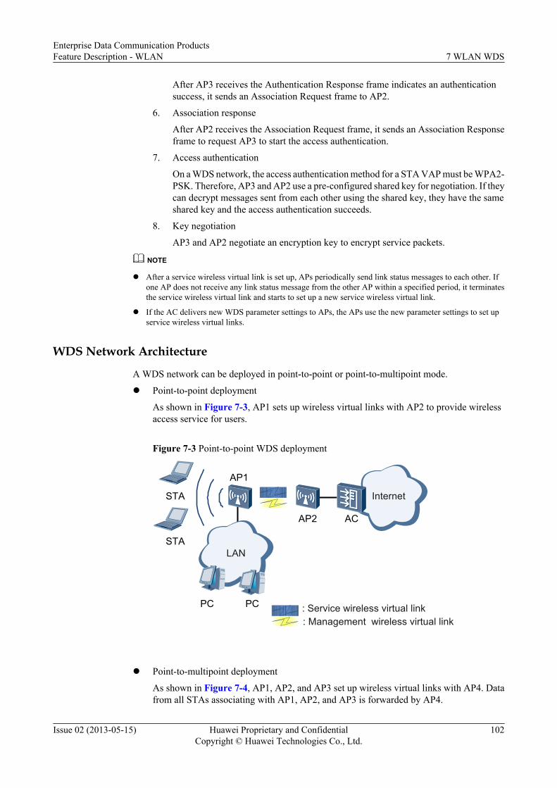
After AP3 receives the Authentication Response frame indicates an authenticationsuccess, it sends an Association Request frame to AP2.
6. Association response
After AP2 receives the Association Request frame, it sends an Association Responseframe to request AP3 to start the access authentication.
7. Access authentication
On a WDS network, the access authentication method for a STA VAP must be WPA2-PSK. Therefore, AP3 and AP2 use a pre-configured shared key for negotiation. If theycan decrypt messages sent from each other using the shared key, they have the sameshared key and the access authentication succeeds.
8. Key negotiation
AP3 and AP2 negotiate an encryption key to encrypt service packets.
NOTE
l After a service wireless virtual link is set up, APs periodically send link status messages to each other. Ifone AP does not receive any link status message from the other AP within a specified period, it terminatesthe service wireless virtual link and starts to set up a new service wireless virtual link.
l If the AC delivers new WDS parameter settings to APs, the APs use the new parameter settings to set upservice wireless virtual links.
WDS Network Architecture
A WDS network can be deployed in point-to-point or point-to-multipoint mode.
l Point-to-point deployment
As shown in Figure 7-3, AP1 sets up wireless virtual links with AP2 to provide wirelessaccess service for users.
Figure 7-3 Point-to-point WDS deployment
AP1
AP2
LAN
Internet
AC
PC
STA
STA
PC : Service wireless virtual link: Management wireless virtual link
l Point-to-multipoint deployment
As shown in Figure 7-4, AP1, AP2, and AP3 set up wireless virtual links with AP4. Datafrom all STAs associating with AP1, AP2, and AP3 is forwarded by AP4.
Enterprise Data Communication ProductsFeature Description - WLAN 7 WLAN WDS
Issue 02 (2013-05-15) Huawei Proprietary and ConfidentialCopyright © Huawei Technologies Co., Ltd.
102

Figure 7-4 Point-to-multipoint WDS deployment
AP1
AP4
LAN
Internet
ACAP2
AP3
LAN
PC
STA
STA
STA
STA
PC
STA
: Service wireless virtual link: Management wireless virtual link
7.3 ApplicationsIn WDS application, APs can be deployed in the hand-in-hand or back-to-back mode.
Hand-in-Hand WDS NetworkingAs shown in Figure 7-5, AP1 is a single-band AP that works at 2.4 GHz frequency band; AP2and AP3 are all dual-band APs. AP1 and AP2 use 2.4 GHz radio to set up wireless virtual links(WVLs), while AP2 and AP3 use 5 GHz radio to set up WVLs. AP3 connects STAs to theWLAN through the 2.4 GHz radio. On a hand-in-hand WDS network, AP1, AP2, and AP3 usedifferent radios to set up WVLs.
Enterprise Data Communication ProductsFeature Description - WLAN 7 WLAN WDS
Issue 02 (2013-05-15) Huawei Proprietary and ConfidentialCopyright © Huawei Technologies Co., Ltd.
103

Figure 7-5 Hand-in-hand WDS networking applications
: Service wireless virtual link: Management wireless virtual link
AC
STASTA
Switch
PC PC
AP1(root)
AP2(root/leaf)
AP3(leaf)
Internet
2.4G5G
NOTEIn the figure, AP2 on 2.4 GHz radio functions as a leaf node for AP1 and AP2 on 5 GHz radio functionsas a root node for AP3.
Back-to-Back WDS NetworkingIn outdoor scenarios, such as school campus, plantations, and mountain areas, wired networksare difficult to deploy. When networks to be connected are far from each other or blocked byobstacles, APs can be cascaded as trunk bridges in back-to-back mode. This networking ensuressufficient bandwidth on wireless links for long distance data transmission. Figure 7-6 showsthe back-to-back WDS networking.
Enterprise Data Communication ProductsFeature Description - WLAN 7 WLAN WDS
Issue 02 (2013-05-15) Huawei Proprietary and ConfidentialCopyright © Huawei Technologies Co., Ltd.
104

Figure 7-6 Back-to-back WDS networking
: Service wireless virtual link: Management wireless virtual link
AC
STASTA
Switch
PC
PC
AP1(root)
AP2(leaf)
AP4(leaf)
STASTA STASTA
AP3(root)
AP5(leaf)
AP6(leaf)
Internet
7.4 References
The following table lists the reference for this feature.
Document Description Remarks
IEEE 802.11 Wireless LAN communicationsstandards
-
Enterprise Data Communication ProductsFeature Description - WLAN 7 WLAN WDS
Issue 02 (2013-05-15) Huawei Proprietary and ConfidentialCopyright © Huawei Technologies Co., Ltd.
105

8 WLAN Mesh
About This Chapter
8.1 Introduction to WLAN Mesh
8.2 Principles
8.3 Applications
8.4 References
Enterprise Data Communication ProductsFeature Description - WLAN 8 WLAN Mesh
Issue 02 (2013-05-15) Huawei Proprietary and ConfidentialCopyright © Huawei Technologies Co., Ltd.
106

8.1 Introduction to WLAN Mesh
DefinitionA wireless mesh network (WMN) is a communications network that consists of multiplewirelessly connected APs in a mesh topology and connects to a wired network through a portalnode or two portal nodes.
PurposeOn a traditional WLAN, APs exchange data with STAs using wireless channels and connect toa wired network through uplinks. If no wired network is available before a WLAN is constructed,it takes much time and money to construct a wired network. If positions of some APs on a WLANare adjusted, the wired network must be adjusted accordingly, increasing the difficulty innetwork adjustment. A traditional WLAN requires a long construction period and has a highcost and poor flexibility, so it does not apply to emergency communication, wireless MANs, orareas that lack weak wired network infrastructure. The construction of a WMN requires onlyAPs to be installed, which greatly speeds up network construction.
A WMN allows APs to wirelessly connect to each other, solving the preceding problems. AWMN has the following advantages:l Fast deployment: Mesh nodes can be easily installed to construct a WMN in a short time,
much shorter than the construction period of a traditional WLAN.l Dynamic coverage area expansion: As more mesh nodes are deployed on a WMN, the
WMN coverage area can be rapidly expanded.l Robustness: A WMN is a peer network that will not be affected by the failure of a single
node. If a node fails, packets are forwarded to the destination node along the backup path.l Flexible networking: An AP can join or leave a WMN easily, allowing for flexible
networking.l Various application scenarios: Besides traditional WLAN scenarios such as enterprise
networks, office networks, and campus networks, a WMN also applies to scenarios suchas large-scale warehouses, docks, MANs, metro lines, and emergency communications.
l Cost-effectiveness: Only MPPs need to connect to a wired network, which minimizes thedependency of a WMN on wired devices and saves costs in wired device purchasing andcable deployment.
BenefitsA WMN saves cables required between mesh nodes while providing path redundancy andrerouting functions as a distributed network. Therefore,l When a new AP is added to a WMN, the AP can automatically connect to the WMN and
determine the optimal multi-hop transmission path after being powered on.l When an AP is moved from a WMN, the WMN can automatically discover the topology
change and adjust communication routes to obtain the optimal transmission path.
8.2 Principles
Enterprise Data Communication ProductsFeature Description - WLAN 8 WLAN Mesh
Issue 02 (2013-05-15) Huawei Proprietary and ConfidentialCopyright © Huawei Technologies Co., Ltd.
107

Concepts
Figure 8-1 Networking diagram
LAN
AC
MPP MP1 MP2
MP3MP4
STA1 STA2
STA3
Mesh link
User access
A WMN includes the following devices:
l Mesh point (MP): a mesh-capable node that uses IEEE 802.11 MAC and physical layerprotocols for wireless communication. This node supports automatic topology discovery,automatic route discovery, and data packet forwarding. MPs can provide both mesh serviceand user access service.
l Mesh point portal (MPP): an MP that connects to a WMN or another type of network. Thisnode has the portal function and enables mesh nodes to communicate with externalnetworks.
l Neighboring MP: an MP that directly communicates with another MP or MPP. Forexample, in Figure 8-1, MP2 is the neighbor of MP1.
l Candidate MP: a neighboring MP with which an MP prepares to establish a mesh link.
l Peer MP: a neighboring MP that has established a mesh connection with an MP.
Implementation
The establishment of a mesh link includes mesh neighbor discovery and mesh connectionmanagement.
MESH NEIGHBOR DISCOVERY
1. Discover a mesh neighbor.
Before constructing a WMN, an MP needs to discover neighboring MPs. An MP can obtainneighboring MP information through active or passive scanning, similar to STA access toWLANs.
Enterprise Data Communication ProductsFeature Description - WLAN 8 WLAN Mesh
Issue 02 (2013-05-15) Huawei Proprietary and ConfidentialCopyright © Huawei Technologies Co., Ltd.
108

l Active scanning: An MP periodically sends a wildcard Mesh Probe Request frame (amesh management frame with the SSID length 0) in a specified channel to search for aneighboring MP.
l Passive scanning: An MP listens on the Mesh Beacon frames sent from neighboringMPs in each channel to obtain neighboring MP information. A Beacon frame containsinformation including the Mesh ID.
2. Update the neighbor relationship table.Each MP has a neighbor relationship table that contains information about four types ofneighboring nodes: common AP neighbors, nodes of other WMNs, candidate MPs, andpeer MPs.l In active scanning, if a neighboring MP finds that the received Mesh Probe Request
frame is a wildcard frame, it sends a Mesh Probe Response frame that contains the MeshID and other required information to the MP. The MP checks whether the Mesh ID inthe received Mesh Probe Response frame is the same as the local Mesh ID. If the twoMesh IDs are the same, the MP records the neighboring MP as a candidate MP in theneighbor relationship table.
l In passive scanning, if the MP finds that the Mesh ID in the Mesh Beacon frame receivedfrom a neighboring MP is the same as the local Mesh ID, the MP records the neighboringMP as a candidate MP in the neighbor relationship table.
Mesh Connection Management
Mesh connection management involves two phases: mesh connection establishment and meshconnection teardown. The two phases are implemented using three types of Mesh Action frames:Mesh Peering Open, Mesh Peering Confirm, and Mesh Peering Close frames.
Figure 8-2 Mesh connection management process
Mesh Peering Open
Mesh Peering Confirm
Mesh Peering ConfirmMesh Peering Open
Security Negotiation & Data forwarding
Mesh Peering Close
Mesh Peering Close
MP1 MP2
1. Mesh connection establishmentAn MP can initiate a mesh connection with a candidate MP. The two MPs are peers andexchange Mesh Peering Open and Mesh Peering Confirm frames to establish a meshconnection.
Enterprise Data Communication ProductsFeature Description - WLAN 8 WLAN Mesh
Issue 02 (2013-05-15) Huawei Proprietary and ConfidentialCopyright © Huawei Technologies Co., Ltd.
109

After the two MPs establish a mesh connection, they start the key negotiation phase. Thetwo MPs can forward mesh data only after key negotiation succeeds.
2. Mesh connection teardownEither of the two MPs that establish a mesh connection can send a Mesh Peering Closeframe to the other MP to tear down the mesh connection. After receiving the Mesh PeeringClose frame, the other MP needs to respond with a Mesh Peering Close frame.
Mesh RoutingOn a WMN, multiple mesh links are available between any source and destination, and thetransmission quality of these mesh links varies according to the surrounding environment.Therefore, routing protocols are required on the WMN. The Hybrid Wireless Mesh Protocol(HWMP) defined in the 802.11s standard can address routing issues.
The following route management frames are defined in HWMP:l Root Announcement (RANN) frame: used to announce the presence of an MPP.
– An MPP periodically broadcasts a RANN frame.– After an MP receives a RANN frame, the MP reduces the time to live (TTL) of the
frame by 1, updates the path metric, and broadcasts the frame. After an MP reads aRANN frame, the MP checks whether the gateway specified in the RANN frame existsin the local gateway list. If the gateway exists in the local gateway list, the MP updatesthe gateway information in the gateway list according to the information in the RANNframe. Otherwise, the MP adds gateway information to the gateway list.
l Proxy Update (PU) and Proxy Update Confirm (PUC) frames– An MP sends a PU frame to an MPP periodically or when the MP detects changes of
its associated STA. The PU frame contains information about the STA associating withthe MP.
– The MPP sends a PUC frame to the MP after receiving the PU frame from the MP.l Route Request (RREQ) and Route Reply (RREP) frames: In on-demand routing mode, the
source node broadcasts a RREQ frame to establish a route to the destination node. Afteran MP receives the RREQ frame, the MP responds with a RREP frame.
A WMN supports two routing modes: on-demand routing and proactive routing.l On-demand routing: The source node broadcasts a RREQ frame to establish a route to the
destination node. After receiving the RREQ frame, a transit node checks the frame. If theRREQ frame contains a sequence number larger than or equal to the sequence number ofthe previous frame but has a lower metric, the transit node creates and updates the route tothe source node. If the transit node has no route to the destination route, the transit nodecontinues forwarding the RREQ frame.
l Proactive routing: A root node periodically broadcasts a RANN frame. When a mesh nodereceives a RANN frame and needs to create or update the route to the root node, the meshnode unicasts a RREP frame to the root node and broadcasts the RANN frame. Then, theroot node creates a reverse path from the root node to the source node, and the mesh nodecreates a forwarding path from the root node to the source node.
HWMP combines on-demand routing and proactive routing to ensure that data frames are alwaystransmitted on mesh links with the best transmission quality.
Huawei develops and optimizes the proprietary mesh routing protocol based on the 802.11sstandard to implement route load balancing. The mesh routing protocol has the followingcharacteristics:
Enterprise Data Communication ProductsFeature Description - WLAN 8 WLAN Mesh
Issue 02 (2013-05-15) Huawei Proprietary and ConfidentialCopyright © Huawei Technologies Co., Ltd.
110

l Reduces the number of times frames are forwarded during the wireless link establishmentand constructs the forwarding topology based on the path with the minimum hops from thesource node to the destination node.
l Selects paths dynamically based on the link-quality parameters including the expectedtransmission count (ETX) and expected transmission time (ETT) to implement loadbalancing.
Zero Touch ConfigurationOn a WMN that uses the centralized WLAN architecture (AC+Fit AP), you only need to performa few AP management configurations on the AC without having to log in to APs to perform anyconfiguration. APs can then connect to the AC. This function facilitates the deployment of alarge number of APs. Figure 8-3 shows how zero touch configuration is implemented.
Figure 8-3 Implementation of zero touch configuration
1. Establish a temporary mesh connection
2. Obtain an IP address
4. Tear down the mesh connection
3. Discover the AC and obtain the AC configuration
5. Use the new configuration to establish a formal, secure mesh link
7. If all the faulty mesh links cannot be restored, go online again using the default mesh configuration
MP1 MP2 DHCP Server AC
6. Establish a secure CAPWAP tunnel
1. After MP1 is powered on, it exchanges Mesh Peering Open and Mesh Peering Confirmframes with MP2 that has associated with the AC using information including the defaultMesh ID and pre-shared key. MP1 establishes a temporary insecure mesh connection withMP2 and establishes a route to the MPP.
2. MP1 obtains an IP address and AC's IP address from the DHCP server through the meshconnection.
3. MP1 discovers and associates with the AC through the mesh connection and establishes atemporary CAPWAP tunnel to obtain the configuration from the AC.
4. After MP1 obtains the new configuration, it sends a Mesh Peering Close frame to tear downthe temporary insecure mesh connection.
5. MP1 resets automatically and exchanges Mesh Peering Open and Mesh Peering Confirmframes with MP2 using the new mesh configuration for key negotiation. After MP1 andMP2 negotiate the key for communication, the two MPs establish a formal secure meshlink.
Enterprise Data Communication ProductsFeature Description - WLAN 8 WLAN Mesh
Issue 02 (2013-05-15) Huawei Proprietary and ConfidentialCopyright © Huawei Technologies Co., Ltd.
111

6. MP1 re-establishes a secure CAPWAP tunnel with the AC using the new configuration.
7. When MP1 cannot establish a mesh link with MP2 within a long period, the defaultconfiguration is restored, and the whole process starts from step 1 until MP1 establishes asecure CAPWAP tunnel with the AC using the new configuration.
8.3 Applications
Mesh Wireless Bridging
In Figure 8-4, AP1 to AP3 provide network access service for wired and wireless users. Thethree APs, however, cannot access the Internet in wired mode because of geographical orenvironmental restrictions. AP1 to AP3 can work with AP4 to build a WMN so that wirelessusers can connect to the Internet.
Figure 8-4 Mesh wireless bridging
AP1
AP4 ACAP2
AP3
STA
STA
STA
STA
5.8 GHz mesh link
2.4 GHz access network
Internet
STA
Access Switch
WMN with One MPP
In Figure 8-5, AP2 to AP5 provide network access service for wireless users, and AP1 provideswired access to the Internet. AP1 to AP5 are fully meshed to establish a secure, auto-configured,and self-healing outdoor WMN, which facilitates fast and cost-effective WLAN deployment inoutdoor environment where cabling is difficult.
Enterprise Data Communication ProductsFeature Description - WLAN 8 WLAN Mesh
Issue 02 (2013-05-15) Huawei Proprietary and ConfidentialCopyright © Huawei Technologies Co., Ltd.
112

Figure 8-5 WMN with one MPP
AC
AP1
AP2
Mesh link
AP3
AP4 AP5
Internet
STA access network
STA1
STA2 STA3
STA4
WMN with Multiple MPPs
In Figure 8-6, AP1 and AP11 provide wired access to the Internet. AP2 to AP5 provide networkaccess service for wired and wireless users in Area 1, and AP7 to AP10 provide network accessservice for wired and wireless users in Area 2. AP6 resides in the overlapping area between Area1 and Area 2.
An MPP and MPs that establish mesh links with the MPP use the same wireless channels. Ifnetwork access service needs to be provided for different areas, multiple MPPs need to work indifferent channels to prevent MPs from preempting wireless channels and improve coverageperformance. Each MP can select the MPP with the minimum hops from the MP as the gatewayto connect the wired network.
Enterprise Data Communication ProductsFeature Description - WLAN 8 WLAN Mesh
Issue 02 (2013-05-15) Huawei Proprietary and ConfidentialCopyright © Huawei Technologies Co., Ltd.
113

NOTEIf an AP connects to different MPPs through a WMN, for example, AP6 in Figure 8-6 connects to two MPPs(AP1 and AP11), AP6 must support 2.4 GHz and 5 GHz frequency bands, while AP1 and AP11 must work indifferent frequency bands. An AP can connect to a maximum of two MPPs on a WMN.
Figure 8-6 WMN with multiple MPPs
AC
AP1
AP2
Mesh link
AP3
AP4 AP5
AP7 AP8
AP10 AP9
Area 1
Area 2
AP6
AP11
Internet
8.4 References
The following table lists the references for this document.
Table 8-1 References
Document Description
IEEE 802.11s WLAN Mesh Standard
Enterprise Data Communication ProductsFeature Description - WLAN 8 WLAN Mesh
Issue 02 (2013-05-15) Huawei Proprietary and ConfidentialCopyright © Huawei Technologies Co., Ltd.
114

9 WLAN Positioning
About This Chapter
9.1 Introduction to Wireless Positioning
9.2 Principles
9.3 References
Enterprise Data Communication ProductsFeature Description - WLAN 9 WLAN Positioning
Issue 02 (2013-05-15) Huawei Proprietary and ConfidentialCopyright © Huawei Technologies Co., Ltd.
115

9.1 Introduction to Wireless Positioning
Definition
WLAN positioning involves WLAN tag positioning and terminal positioning.
WLAN tag positioning technology uses radio frequency identification (RFID) devices and apositioning system to locate a target through the WLAN. An AP sends the collected RFID taginformation to a positioning server. The positioning server then computes the physical locationand sends the location data to a third-party device so that users can view the location of a targetthrough maps and tables.
Terminal positioning technology uses APs to collect strength information about radio signals inthe surrounding environment to locate Wi-Fi terminals and rogue APs. The APs report thecollected information to a positioning server. The positioning server computes locations ofterminals based on AP's location and data received from the APs, and presents the computingresults to users through a display terminal.
Purpose
Wireless positioning technology helps users efficiently implement network management andkey asset control.
9.2 Principles
9.2.1 WLAN tag positioning
Concepts
As shown in Figure 9-1, the terminal positioning system includes at least three APs, one or moreRFID tags, one or more ACs, a positioning server, and a location display terminal. Functions ofeach component are as follows:
l Radio frequency identification (RFID) tag: is manufactured by tag vendors to carry wirelesslocation system data. For example, AeroScout manufactures RFID tags that are often placedor pasted to the objects to be located. The tag is a source device that needs to be locatedand can periodically send radio waves to surrounding devices.
l AP: receives location information sent by an RFID tag and forwards the information to theAC or directly sends it to a positioning server.
l AC: forwards the configuration instruction from the positioning server to APs. It can alsoforward location information received from an AP to the positioning server.
l Positioning server: computes the RFID tag location using a location algorithm (for example,three-point positioning) after receiving the location information and provides the computeddata to user systems, including the system management software and image software.
Enterprise Data Communication ProductsFeature Description - WLAN 9 WLAN Positioning
Issue 02 (2013-05-15) Huawei Proprietary and ConfidentialCopyright © Huawei Technologies Co., Ltd.
116

Figure 9-1 Typical networking for the WLAN tag positioning system
AC
Switch
AP1
AP2
AP3
Internet
Positioning server
RFID Tag
Implementation
Figure 9-2 Working mechanism of the WLAN tag positioning system
RFID Tag AP Switch AC Positioning server
UDP encapsulation
Tag Message Tag Report
Wireless packets sent by tagsTag information encapsulated by the AP
Figure 9-2 shows how wireless positioning is implemented.
Enterprise Data Communication ProductsFeature Description - WLAN 9 WLAN Positioning
Issue 02 (2013-05-15) Huawei Proprietary and ConfidentialCopyright © Huawei Technologies Co., Ltd.
117

1. The RFID tag sends a tag message.The RFID tag only sends 802.11 frames periodically to provide location information anddoes not need to connect to a WLAN.To enable more APs to receive tag messages, the RFID tag sends a tag message in allchannels each time. A tag message usually contains location information required by apositioning server, and the frame format of the tag message varies depending on the vendor'stag device. A tag of AeroScout is used as an example here.l The Address1 field indicates the destination address, which is a specified multicast
address. The AP identifies an 802.11 packet as a tag message through the multicastaddress.
l The Address2 field indicates the source address, which is the MAC address of the RFIDtag. According to this field, the wireless positioning system collects information aboutthe same RFID tag that is received from different APs.
l The Address3 field indicates RFID tag information. The most important informationin this field is about the channel that transmits the tag message. The AP determineswhether the channel information in the received tag message matches its workingchannel.
l The Address4 field is available only when the tag message needs to be transmitted ona wireless distribution system (WDS) network. This field indicates the extended RFIDtag information.
For details about the 802.11 MAC frame format, see 1.2.2 802.11 Standards.2. The AP receives the tag message and forwards it to the positioning server.
a. When receiving a tag message frame, the AP records the location information such asthe received signal strength indicator (RSSI), timestamp, rate, and channel of theframe. The RSSI is the most important information because the positioning serveruses it to determine the distance between a tag and an AP. To ensure that the RSSI isaccurate, the AP must filter out the tag messages received from adjacent channels. Forexample, when working in channel 1, the AP may receive the frames sent from a tagin channel 2. The RSSI is low because the AP and tag are located in different channels.As a result, the positioning server mistakenly considers that the tag is far away fromthe AP.
b. The AP encapsulates all location information obtained from tag message frames intoa UDP packet (tag report) and sends the packet to the positioning server directly orthrough the AC.The required location information and report mode vary depending on the vendor'spositioning server. For example, the Ekahau Positioning Server requires that thelocation information should contain content of the tag message frames and the APshould report tag message frames immediately when receiving them; the AeroScoutPositioning Server does not need content of the tag message frames and allows theAP to periodically report collected location information.The destination IP address and port number of a tag report packet are configured onthe AC. If the destination address is set to the IP address of the positioning server, thetag report packet is directly sent to the positioning server. If the destination address isset to the AC IP address, the tag report packet is sent to the AC and forwarded by theAC to the positioning server. This configuration is used when the AP cannot be directlyconnected to the positioning server.
c. The positioning server computes the location information.To accurately determine the tag location, the positioning server must receive locationinformation about a tag from at least three APs. After receiving the tag information,
Enterprise Data Communication ProductsFeature Description - WLAN 9 WLAN Positioning
Issue 02 (2013-05-15) Huawei Proprietary and ConfidentialCopyright © Huawei Technologies Co., Ltd.
118

the positioning server uses the built-in computing algorithm to compute the taglocation according to information including the RSSI, SNR, radio mode, the importedmap, and AP positions. Then, the positioning server sends the location information tothe graphical interface of the third-party device for presentation.
9.2.2 Terminal Positioning
Basic ConceptsAs shown in Figure 9-3, the terminal positioning system includes at least three APs, one or moreACs, a positioning server, and a location display terminal. Functions of each component are asfollows:
l AP: The APs collect wireless signals. The APs periodically switch channels to collectstrength information about terminal signals in the surrounding environment on each channeland report the collected information to the positioning server.
l AC: The AC delivers terminal positioning configurations to the APs. In addition, the ACalso classifies and filters the information received from the APs based on the device type(such as authorized terminals and rogue APs).
l Positioning server: The positioning server computes the signal transmission modelaccording to locations of APs and obstacles, and calculates locations of terminals based onthe information received from each AP. An NMS device is usually used as a positioningserver.
l Display terminal: The display terminal draws maps and displays terminal locations on themap. The display terminal can be integrated to the positioning server.
Enterprise Data Communication ProductsFeature Description - WLAN 9 WLAN Positioning
Issue 02 (2013-05-15) Huawei Proprietary and ConfidentialCopyright © Huawei Technologies Co., Ltd.
119

Figure 9-3 Typical networking for the terminal positioning system
AC
Switch
AP1
AP2
AP3
Internet
Positioning server
Rogue APs Wi-Fi terminals
Display terminal
Implementation Principles
Terminal positioning technology locates terminals as follows:
1. APs collect strength information about radio signals and forwards the information to thepositioning server.
a. The APs periodically switch channels to collect frames sent from terminals in thesurrounding environment on each channel and record frame information includingRSSI information, timestamp, data rate, and channel information. RSSIs are essentialin determining whether a terminal is near or far from the APs.
b. The APs encapsulate the collected radio signal information into UDP packets andreport the data to the positioning server in the following two modes:l APs report collected data to the AC. Then, the AC reports the data to the positioning
server.When the network between the APs and positioning server is not reachable, theAPs report data to the AC first. The AC then filters information about terminalsand rogue APs before reporting the data to the positioning server.
Enterprise Data Communication ProductsFeature Description - WLAN 9 WLAN Positioning
Issue 02 (2013-05-15) Huawei Proprietary and ConfidentialCopyright © Huawei Technologies Co., Ltd.
120

l The APs directly report the collected data to the positioning server.
If the network between the APs and positioning server is reachable, and the AC isnot required to identify unauthorized APs, configure the APs to directly send datato the positioning server, which decreases CPU usage of the AC and reducesimpacts of the positioning function on services.
2. The AC reports the information received from APs to the positioning server.
As shown in Figure 9-4, after receiving information from the APs, the AC processes theinformation as follows:
a. Determine whether the data received from the APs is positioning data. If not, the datais processed in other ways.
b. If the AC receives the location data, the AC processes the data in the following way:if the data is about terminal locations, the AC reports the data directly to the positioningserver; if the data is about authorized AP locations, the AC discards the data; if thedata is about rogue AP locations, the AC reports the data to the positioning server.
Figure 9-4 Processing positioning information
The AC receives data from APs.
Does the AC receive the
location data?
Is the data about terminal location?
The AC reports the data to the positioning
server
To other processes
Is the data about rogue AP location?
Discard
No
Yes
Yes Yes
No No
3. The positioning server computes the location information.
The positioning process involves the offline phase and online phase.
a. Offline phase: The positioning server divides the whole network into multiple equalarea grids, computes the signal transmission model according to environment features(indoor/outdoor and obstacle features), calculates the theoretical differences among
Enterprise Data Communication ProductsFeature Description - WLAN 9 WLAN Positioning
Issue 02 (2013-05-15) Huawei Proprietary and ConfidentialCopyright © Huawei Technologies Co., Ltd.
121

RSSIs of a STA in the grid to all APs based on the imported AP location information,and stores the data into the database.
b. Online phase: At least three APs report terminal information to the positioning serverafter receiving the terminal information. The positioning server compares theinformation received from the APs with the information in the database to obtain thelocation of the terminal.
9.3 References
None
Enterprise Data Communication ProductsFeature Description - WLAN 9 WLAN Positioning
Issue 02 (2013-05-15) Huawei Proprietary and ConfidentialCopyright © Huawei Technologies Co., Ltd.
122