
Thermodynamic and Economic Feasibility of Energy Recovery ...

Prakash Adhikari
Feasibility study of waste heat recovery from laundry facility Case study: Mr Washing Man Oy
Helsinki Metropolia University of Applied Sciences
Degree:Bachelor of Engineering
Degree Programme:Environmental Engineering
Thesis
6 February 2017

i
Author Title Number of Pages Date
Prakash Adhikari Feasibility study of waste heat recovery form laundry facility: Case study Mr Washing Man Oy 40 pages 6 February 2017
Degree Bachelor of Engineering
Degree Programme Environmental Engineering
Specialisation option Renewable Energy
Instructors
Antti Tohka, Senior Lecturer Helsinki Metropolia University of Applied Sciences Teuvo Heikkinen, Chairman of the Board of Mr. Washing Man Ltd
The purpose of this thesis was to study the feasibility of waste heat recovery from laundry
facility of a company Mr Washing Man Oy. The usefulness of heat recovery was deter-
mined from wastewater leaving the washing machine at 60oC and 0.11 kg/s and hot air
exiting from dryer at a temperature of 90oC and at a flow rate of 1.5 kg/s. Thesis project
focused on the description of system, calculation of the energy savings, case studies of
heat exchangers suitable for waste heat recovery system and pinch analysis of the sys-
tem. Distance between recovery system and consumer, compatibility, accessibility, quality
of heat source, upgrading requirement, flow rate and legislation were also studied for fea-
sibility considerations.
The result of the thesis project suggests that a significant amount energy available in
waste water and dryer exhaust air that can be harnessed, and this would save approxi-
mately €40,000 per year. Extracting 650 MWh of energy per year is a compelling benefit
for climate and environment as well. In terms of maintaining minimum distance between
recovery system and consumer, accessibility and legislation, the heat recovery is feasible
with some necessity for further considerations in flow rate, quality of heat and compatibility
because of their correlations.
Experimental observations within the process for parameters such as temperature, mass
flow could lead to more reliable and accurate energy output and savings. For further re-
search, study of heat pump in series in colder exhaust from heat exchanger to heat the
water further is recommended. This integration of heat pump and heat exchanger might
harness higher overall energy from the process compare than an individual system.

ii
Keywords dry cleaner, laundry, heat exchangers, heat recovery, energy saving, pinch analysis

iii
Acknowledgement
It was a rewarding experience writing the first thesis of my career. I believe this
achievement will assist in my future academic and professional career.
I am profoundly indebted to my supervisor Mr. Antti Tohka, Principal Lecturer Helsinki
Metropolia University of Applied sciences for his valuable time and knowledge shared
throughout the thesis work.
I am grateful to Teuvo Heikkinen, Chairman of the Board of Mr. Washing Man Ltd for
providing this thesis opportunity and support in the completion of this thesis.
Finally, I am thankful to my family and friends who were always there for suggestions
and guidance. Special thank goes to Lorant Katona Farnas for accepting my proposal
to be my opponent for the thesis.
Despite of support and guidance throughout the project, any errors and/or omissions in
this thesis work are solely my own.

iv
Contents
List of Abbreviations 1
1. Introduction 2
2. Background 3
3. Literature review 4
4. System description 6
4.1 Wastewater 6
4.2 Dryer exhaust 7
5 Review on heat exchangers 8
6 Heat exchangers application characteristics 14
7 Heat exchanger analysis 16
8. Calculations 17
9. Case study 20
9.1 Wastewater 20
9.2 Dryer exhaust 22
10. System placement 24
11. Feasibility considerations 25
12. Financial feasibility 27
13. Pinch analysis 29
14. Result 36
15. Conclusions 38
References 39

1
List of Abbreviations
CHP Combined heat and power
GCC Grand composite curve
HCC Hot composite curve
CCC Cold composite curve
HP Heat pump
LMTD Log mean temperature difference
NTU Number of transfer units
ϵ Effectiveness
EHHE Ecowec hybrid heat exchanger
U Overall heat transfer coefficient of heat exchanger
Tc,in Inlet temperature of cold water
Tc,out Outlet temperature of cold water
Th,in Inlet temperature of heat source
Th,out outlet temperature of heat source
Cp Specific heat capacity
ΔT Temperature difference
Q Rate of heat transfer
m mass flow rate
Ch Heat capacity rate of heat source
Cc Heat capacity rate of cooler source
HVAC Heating ventilation and air conditioning

2
1. Introduction
This project aimed to study the feasibility of waste heat recovery from laundry facility.
The focus was on the usefulness of heat recovery from waste water leaving washing
machine and hot air exiting dryer at specific temperature and flow rates.
A significant amount of heat energy in residential buildings is released into atmosphere
along with wastewater and dryer exhaust air. This process of discharging of heat to
atmosphere does not seem to be slowing down. In Finland, on average, 155 litres of
water is used per person per day, of which 13% is used by the laundry [1]. 15-30% of
heat losses take place via waste hot water [1]. According to (Motiva, 2012) 7.1 TWh of
energy is being flushed into the drain each year, and up to 4 TWh of this waste heat
could be recovered and reused profitably each year. This amounts to the burning of
more than 25% of coal for energy production. A considerable amount of fossil fuel is
being burnt for generating energy for consumption in households, industries and organ-
izations. This exploitation of traditional fuel causes CO2 emissions leading to global
warming. This impact on environment affects flora and fauna including human health.
Generally, heat is extracted either after water is treated at a treatment plant or in a heat
recovery plant, by then, a considerable amount of heat is lost already. Sewage heat
recovery technology has been practiced throughout the world in recent years with dif-
ferent capacity. Switzerland has been practicing it for a long time and also some other
countries including Germany and the Netherlands. In Finland Helsinki Energy (HELEN)
has been using sewage heat recovery as a supplement to its district heating and for a
cooling plant in Katri Vala, Helsinki. In winter, the wastewater after treatment from Viikki
wastewater treatment facilities is pumped to the heating and cooling plant where heat
energy is extracted using a heat pump. Different inventions and approaches in
wastewater heat recovery are also described in chapter 9.
The application of a waste heat recovery system can play a crucial role in saving heat
loss, reduce adverse impact on environment and make profit for the companies at the
same time. The energy harnessed can be utilized for different purposes such as hot
water utilities, space heating and heating ventilation air. Implementation of waste heat
recovery would contribute offsetting greenhouse emission in some proportion. Energy
saving can be achieved not only by recovering heat as required instead but also by
preheating the source. According to Helppolainen [1], when temperature of domestic

3
water is preheated from 8oC to 15oC before the heating system, this will cut 30% of the
energy required for domestic water heating.
2. Background
This thesis work was done for the company Mr Washing Man Oy, located in Käpylä
district Helsinki (see Figure 1). The company was renamed to Mr Washing Man Oy
from Pesula Vaahto and prior water used to be heated by wood burning. Now the com-
pany owns 1 industrial scale and 1 small scale dryers including 2 washing machines.
Hotels and restaurants are the major customers of the company but the, company is
not interested in personal clothes due to lack of space to store. The commercial facili-
ties need the clothes as soon as possible, which is more convenient for Mr Washing
Man Oy. The company offers a service of collecting the clothes from the site and as
well as returning them after being washed and dried.
During 1952 Olympic games, the place was used as players’ accommodation. Since
then it has been prohibited to make any modifications in architecture of the building.
But now the neighbourhood people are allowed to own houses and apartments.
The aim of this project was to recover heat from wastewater discharged from washing
machine and from dryer exhaust air. Laundry uses electricity for washing purposes and
ignites natural gas for drying purposes. The excess hot air is released into atmosphere
and hot waste water is drained away in sewage. As stated above, this can have a sig-
nificant effect on the carbon footprint. Washing machines and dryers operate 13 hours
a day and 6 days a week. Laundry processes approximately 100 kg of clothes per day
using 125 m3 of cold and 28 m3 of hot water is used per month.
A limited number of studies have been done in small-scale heat recovery either from
wastewater or dryer exhaust. This thesis aimed to determine whether it would be fea-
sible to recover heat for further utilization where dryer and washing machine operates
certain hours a day. Further utilization of recovered heat by using air-air or air-water
heat exchanger for water heating was investigated. Prospective commercial heat ex-
changers were studied as a case study. This study shed light on the possibilities of
recovering heat from the water exiting washing machine and the hot and moist air exit-
ing from the dryer in small scale. The amount of energy available in the exhaust will be
calculated along with economic considerations. The additional data regarding parame-

4
ters and their values for wastewater and dryer exhaust are explained in chapter 4 Sys-
tem description .
Figure 1 Google image of Laundry Site
3. Literature review
Pulat E.et.al. in [2] have done a thermodynamic and economic analysis of waste heat
recovery potential in textile industry in Turkish textile industry. The study illustrates that
with a heat transfer rate of 2020 kW, heat transfer area of 228.4 m 2 and a 0.92 effec-
tiveness of shell-and tube heat exchanger, the payback period was less than 6 months.
It was explained that parameters such as wastewater inlet temperature, flow rate, cool-
ing water inlet pressure and dead state conditions are crucial factors that affect the
performance of the system.
©OpenstreetMapContri
butors

5
Liu L. et al. [3] have studied the application of exhaust heat recovery from public show-
er facilities via heat pump. They found that the application was beneficial in comparison
with oil-fired, gas fired or even electric boilers in terms of energy consumption, pollution
and operating cost. O. Culha et al.[4] have studied the application of heat exchangers
in sewage heat recovery where researcher have classified different heat exchanger
types according to different features including utilization and construction methodology
applied. Noting the importance of heat exchanger in sewage heat recovery, authors
have claimed that heat exchangers need to be designed according to requirements of
transfer process, and at the same time, the design to overcome fouling, blocking and
corrosion needs to be considered. Alnahhal S. and Spremberg E. [5] found in a sepa-
rate experimental study that in-house wastewater energy is approved as a crucial
source of energy that can be extracted providing a significant impact on hot water de-
mand.
Another study on the laundry dryer exhaust heat recovery in the university dorm was
done by students from Rochester University of Technology [6] found that harnessing
dryer heat is feasible in terms of saving energy and water. Similar experimental study
done by Baggett John et al. [7] concludes that dryer waste heat recovery systems are
feasible for commercial establishment such as hotels, laundromats, and hospitals. The
result suggests that service water at 4oC was able to be heated up to 33oC with a sav-
ing of $3.90 per day which does not seem significant, but still it is technically feasible
and environmentally and socially beneficial.
A major concern in previous studies was about mass flow rate and temperature of exit
water including the quality of waste water. The system can be designed according to
the requirements and in some cases integration of heat exchangers and heat pumps
was suggested to boost the energy available in wastewater.
Very few studies have been found on dryer heat recovery for the purposes of hot water
utility, space heating or any other function. Meanwhile, studies have been done for cap-
turing heat and releasing it within the premises using exhaust deflector, but in most
cases air is dumped into atmosphere. In case of dryer exhaust heat recovery there are
concerns over the source of dryer operation i.e. whether the dryer is electric powered
or gas powered. Electric powered dryer emits less carbon monoxide into the atmos-
phere in comparison to gas-fired hence this factor has also been suggested as a factor
to be taken into account while designing the system.

6
4. System description
The laundry premises operate 2 washing machines and 2 dryers. Introduction of each
source system, their parameters, values and units will be explained in succeeding sec-
tion.
4.1 Wastewater
Company situated in Käpylä district Helsinki operates the washing machines 13 hours
a day and 6 days a week. The operation of the machine depends on the load, and the
operating time is assumed to be fluctuating. The average operation time is considered
to be 13 hours a day from 7 to 20. The machines use hot and cold water both for wash-
ing clothes where 125m3 of cold water from is used from 7 to 20 per month, which is
heated by natural gas whereas, 28m3 of hot water is used, which is heated by the dis-
trict heater heat exchanger.
Figure 2 shows the washing machines and dryers in the site and water exit pipings.
Figure 2. Washing machine and dryer’s (a) and washing machine water exit (b)
In average 100kg of clothes items such as table cloth, bed sheets from restaurant and
other commercial complexes are washed. Personal clothes are not washed in the
laundry facilities due to lack of storage facilities. The exit temperature of waste water
from washing machine is averaged to 60oC. Without conducting an experiment, the
flow rate of exit water was assumed on the basis of cold water used per month, which
gives 0.11 kg/s. The wastewater values are summarized in Table 1.

7
Table 1 Summary of wastewater values
Parameters Values Units
Exit Temperature 60 oC
Flow rate 0.11 kg/s
Specific heat capacity 4.8 kJ/kg.K
Cold water 125 m3
Hot water 28 m3
Operating time 13 hours/day
Washing machine 2
4.2 Dryer exhaust
There are 2 dryers with separate exhaust in the premises: one large-scale, natural gas
heated mangle dryer and other operates electrically. Like the washing machines, dry-
ers are operated 13 hours a day and 6 days a week depending on the load. The man-
gle dryer operates by igniting natural gas. The mangle is a mechanical laundry aid con-
sisting of two rollers in a sturdy frame, connected by cogs and, in its home version,
powered by a hand crank or electrically (Figure 3), mangles are used to press or flatten
sheets, tablecloths, kitchen towels, or clothing and other laundry [8].
Figure 3. Mangle dryer (a) and dryer exhaust (b)

8
As shown in the Figure 3, the dryer exhaust has different exit diameter throughout the
section; therefore the differential diameter was excluded, and it was assumed that the
mass flow was consistent throughout the exhaust. Due to the complexity of measure-
ment, reasonable estimation was made for different parameters such as flow rate and
temperatures. Flow rate of hot flue gases via the exhaust was assumed to be 1.5 kg/s
with 90oC temperature and constant throughout the operation. It was assumed that
most of the flue gases were hot air. Variation of moisture removed from cloth after dry-
ing was not taken into account.
Parameters, values and their units taken into considerations are listed in Table 2.
Table 2 Summary of dryer exhaust values
Parameters Values Units
Temperature 90 oC
Flow rate 1.5 kg/s
Density of air 1.225 kg/m3
Specific heat of air 1.006 kJ/kg.K
Operating time 13 hours/day
No. of dryer 2
Capacity factor not considered
In addition, the parameters for service water to be heated were considered and are
given in Table 3.
Table 3 Summary of service water values
Parameters Values Unit
Inlet temperature 5 oC
Flow rate 0.5 kg/s
Specific heat 4.18 kJ/kg.K
Target temperature 39 oC
5 Review on heat exchangers

9
Different heat exchangers that have been used in waste heat recovery system are de-
scribed below. To accomplish the objective of this project, the appropriate heat ex-
changer was studied based on different initial parameters. The heat exchanger can be
defined as a device which helps to transfer heat from one media to another with differ-
ent temperature levels. The media in heat exchanger could be, for example, liquid-
liquid, air-liquid or air-air which flow either co-current or counter-current. The basic
working principle of the heat exchanger is that transfer of heat takes place between a
medium with high temperature and a medium with low temperature via conduction and
convection. Application of heat exchangers in wastewater heat recovery can be classi-
fied according to the volume flow, temperature, and the place of heat extraction.
There are various heat exchangers in operation depending on the heat transfer pro-
cess, materials, temperatures and the heat exchangers can also be classified depend-
ing on system requirements. The general classification is direct contact heat exchanger
and indirect contact heat exchanger. In direct contact, two medium get mixed, and in
case of indirect contact, heat transfer takes place via surface between hot and cold
medium. The heat exchanger is mostly used either for cooling or heating purposes, so
application of the heat exchanger varies depending on the requirements. Heat ex-
changers are used, for example, in the different sections of CHP power plants, in dis-
trict heating systems, and in waste heat recovery in different process industries. A
schematic illustration of co-current and counter current heat exchangers and their re-
spective graphs are shown in Figure 4 and Figure 5 respectively.
Figure 4 Co-current flow of fluid [9]
In co-current heat exchangers, two active fluid flows in the same direction and their
respective temperature variation curve is shown on the right.

10
Figure 5 Counter-current flow [9]
Counter-current heat exchanger with flow of active fluid is shown in Figure 5. In this
case outlet temperature of the cold fluid can also exceed then outlet temperature of the
hot fluid [9] as shown in graph.
Some of the indirect heat exchangers that are mostly used in waste heat recovery, and
their applications are be described in following sections.
5.1 Compact heat exchanger
Compact heat exchanger is generally used in gas-gas and gas-liquid medium where
the fluid flow is perpendicular to each other making the flow as cross flow. The ad-
vantage of the compact heat exchanger is that it enables the large heat transfer area in
small volume, which is also the design purpose of the compact heat exchanger. The
ratio of the heat transfer surface area of the heat exchanger to its volume is called the
area density, and represented by β. The heat exchanger with β > 700 m2/m3 is classi-
fied as being compact [9]. The examples of the compact heat exchangers are car ra-
diators (1000 m2/m3), glass ceramic gas turbine heat exchangers (6000 m2/m3), the
regenerator of a Stirling engine ( 15,000 m2/m3), and the human lung ( 20,000 m2/m3)
[9].

11
Figure 6 Compact heat exchanger [9]
5.2 Shell-and-tube heat exchanger
The shell-and-tube heat exchanger consists of large numbers of tubes packed inside
the shell. One of the fluid flows inside the tube, while other flows outside. The shell-
and-tube heat exchanger can be further classified depending on the number of shells
and number of shell-passes it contains. These numbers of shell helps in the effective-
ness of heat transfer. These heat exchangers are commonly used in industrial applica-
tions such as oil refineries and other chemical processes and are suitable for high
pressure applications [9]. Meanwhile, due to the large size and weight, these heat ex-
changers are less suitable for automotive and aircraft applications [9].
Figure 7 Shell-and-tube heat exchanger [9]
5.3 Finned tube heat exchanger
In finned tube heat exchanger, heat transfer takes place between the fluids by the con-
duction through the tube wall. Process liquid is pumped through one end of the tube
(whether round or rectangular) which then absorbs or rejects heat to the air or gas de-
pending on the application. The finned tube heat exchangers are employed when one

12
fluid stream is at the higher pressure and/or has a significantly higher transfer coeffi-
cient than that of the other fluid stream [10].
Figure 8 Circular finned tube (a), Plate finned tube (b) and Louvered plate fin flat tube (c) [11]
Three different types of the finned tube heat exchangers are shown in Figure 8. They
differ in the design consideration and their application. Heat pipe, a specialized type of
finned tube heat exchanger has been also used in wastewater heat recovery. The
finned tube heat exchangers are mainly used in industrial and consumer product ori-
ented waste heat recovery applications.
5.4 Plate heat exchanger
The plate heat exchanger consists of series of plates with corrugated flat flow pas-
sages. The hot and the cold fluid flows in alternative passages, where the cold fluid is
surrounded by hot fluid making the heat transfer process more efficient. The size of
heat exchanger can be made larger by simply adding number of plates. The plate heat
exchangers best suits for liquid-liquid heat exchange applications provided that the hot
and the cold fluids are in the same pressure [9].
Figure 9. Plate heat exchanger, plates (b) and heat transfer surface(c) [12]

13
5.5 Gravity film
The gravity film heat exchanger is mostly used in domestic drainage systems where
the flow and the temperatures are not consistent. This is a counter flow heat exchanger
which is vertical in design and extracts heat from the wastewater to heat the water. The
gravity film heat exchanger is installed around the particular section of the drainage
pipe that carries warm water. The simple design, working principle, and little thermal
mass of gravity film heat exchanger makes less effective in larger application. The
sketch of gravity film heat exchanger is shown in Figure 10.
Figure 10 Gravity film heat exchanger [13]
5.6 Helical heat exchanger
The helical heat exchanger is best suited in the process industries such as gas pro-
cessing, refining, petrochemical and chemical industries. Generally processes with high
pressure, temperature, and low flow applications and also according to heat demand
requirements helical heat exchangers are applied.

14
Figure 11 Helical heat exchanger [4]
Some of the heat exchangers used in sewage treatment depending on domestic, sew-
age and after treatment is classified in Table 4.
Table 4 Classification of heat exchangers [4]
Domestic Sewage After treatment
Gravity-film External Type Spray
Spiral/Helical Integrated Type Plate
Plate Modular Type Pressure Pipe
Shell-and-Tube Special design Helical
6 Heat exchangers application characteristics
The classification of different heat exchangers used in wastewater heat recovery on the
basis of temperature, cross-contamination, and working fluids are listed in the Table 5.
Table 5 Operation and application characteristics of heat exchangers [14]
Specifications
of Recovery
unit
Tem
pera
ture
0-1
20
oC
Tem
pera
ture
12
0-
650
oC
Tem
pera
ture
ab
ove
650
oC
Re
cove
rs m
ois
ture
Larg
e
Tem
pera
ture
diffe
ren
ce p
erm
itte
d
Ca
n b
e r
etr
ofit
No
C
ross
co
nta
min
a-
tio
n
Ga
s-g
as
hea
t E
x-
ch
an
ge
r
gas-L
iquid
H
eat
Ex-
ch
an
ge
r
Liq
uid
-Liq
uid
H
eat
Exch
an
ge
r

15
Heat Ex-
changers
Shell-and-
Tube Ex-
changer
√ √ √
√ √ √ √
Finned-tube
Heat Ex-
changer
√ √ √ √ √ √
Waste heat
Boiler
√ √ √ √ √
Spiral Heat
Exchanger
√ √ √ √ √
Concentric
Tube Heat
Exchanger
√ √ √ √ √ √ √
Concentric
Tube Heat
Exchanger
Recuperator
√ √ √ √ √ √
Plate Heat
Exchanger
√ √ √ √ √ √ √ √
Round
around Sys-
tem
√ √ √ √ √ √ √ √
Heat Wheel
Metallic
√ √ √ ** √
Heat wheel
hydroscopic
√ √ √ ** √
Heat Wheel
Ceramic
√ √ √ √ √
Heat Pipe
√ √ * √ √ √
*Allowable temperature and temperature differential limited by the phase equilibrium of
the internal fluid.
** Can be limited to <1% by mass
16
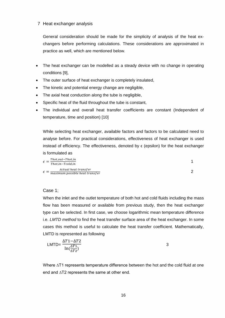
7 Heat exchanger analysis
General consideration should be made for the simplicity of analysis of the heat ex-
changers before performing calculations. These considerations are approximated in
practice as well, which are mentioned below.
The heat exchanger can be modelled as a steady device with no change in operating
conditions [9],
The outer surface of heat exchanger is completely insulated,
The kinetic and potential energy change are negligible,
The axial heat conduction along the tube is negligible,
Specific heat of the fluid throughout the tube is constant,
The individual and overall heat transfer coefficients are constant (Independent of
temperature, time and position) [10]
While selecting heat exchanger, available factors and factors to be calculated need to
analyse before. For practical considerations, effectiveness of heat exchanger is used
instead of efficiency. The effectiveness, denoted by ϵ (epsilon) for the heat exchanger
is formulated as
𝜖 =𝑇ℎ𝑜𝑡,𝑜𝑢𝑡−𝑇ℎ𝑜𝑡,𝑖𝑛
𝑇ℎ𝑜𝑡,𝑖𝑛−𝑇𝑐𝑜𝑙𝑑,𝑖𝑛 1
𝜖 =𝐴𝑐𝑡𝑢𝑎𝑙 ℎ𝑒𝑎𝑡 𝑡𝑟𝑎𝑛𝑠𝑓𝑒𝑟
𝑚𝑎𝑥𝑖𝑚𝑢𝑚 𝑝𝑜𝑠𝑠𝑖𝑏𝑙𝑒 ℎ𝑒𝑎𝑡 𝑡𝑟𝑎𝑛𝑠𝑓𝑒𝑟 2
Case 1;
When the inlet and the outlet temperature of both hot and cold fluids including the mass
flow has been measured or available from previous study, then the heat exchanger
type can be selected. In first case, we choose logarithmic mean temperature difference
i.e. LMTD method to find the heat transfer surface area of the heat exchanger. In some
cases this method is useful to calculate the heat transfer coefficient. Mathematically,
LMTD is represented as following
LMTD= ∆𝑇1−∆𝑇2
ln(∆𝑇1
∆𝑇2)
3
Where ∆T1 represents temperature difference between the hot and the cold fluid at one
end and ∆T2 represents the same at other end.

17
Further using the equation,
Q =U *A*LMTD 4
We can now calculate surface area (A) of the heat exchanger and also overall heat
transfer coefficient (U) provided ∆T1 and ∆T2. It should be noted that the average tem-
perature difference (LMTD) is dependent on flow arrangement and type of construction
of heat exchangers [9]. Equations 3 and 4 are valid for any heat exchanger type given
the temperature differences of end points in a parallel flow case.
Case 2;
When the heat exchanger type and size is known along with flow rates and inlet tem-
peratures then outlet temperatures of two exiting fluids and the heat transfer rate can
be figured out.
In this method, predefined heat transfer effectiveness of heat exchanger (ϵ) is used.
𝜖 =𝑄
𝑄𝑚𝑎𝑥 5
Where Q is actual heat transfer rate and can be determined by
Q= Cc (Tc,out-Tc,in)=Ch(Th,in-Th,out) 6
Qmax represents the maximum possible heat transfer rate in a heat exchanger i.e.
Qmax=Cmin*∆Tmax
Cc and Ch represents the heat capacity rate of the cold and the hot fluid respectively. In
heat exchanger, the heat capacity rate and temperature change are inversely propor-
tional i.e. fluid with higher heat capacity rates experiences lower temperature changes
and vice versa.
Using equation 5 and equation 6 outlet temperatures can be calculated when mass
flow rates and the specific heat capacities of the fluids are available.
8. Calculations
Values of the parameters obtained in the calculations are based on interview with laun-
dry owner, unless otherwise stated. Considering a counter flow heat exchanger,
amount of energy available in wastewater and hot air exhaust is as follows.

18
8.1 Wastewater case
Service water;
Tc,in =5oC
Mass flow (mc) = 0.1112 kg/s
Cp,water = 4.18 kJ/kg.K
Wastewater;
Tc,in =60oC
Mass flow (mh) = 0.1112 kg/s
Cp,wastewater = 4.18 kJ/kg.K
The number of transfer units (NTU) method was used depending on the available fig-
ures.
Ch=mh*Cp,wastewater 7 [Ch ;heat capacity rate at hot side]
Cc=mc*Cp,water 8 [Cc ;heat capacity rate at cold side]
The specific heat of both service and wastewater is assumed to be the same
Ch = 0.465189 kW/K
Cc= 0.465189 kW/K
Cmin= Ch = Ch = 0.465189 kW/K heat capacity rate is same for both the hot and the cold
streams.
Now the maximum heat transfer rate is determined by
Qmax= Cmin(Th,in-Tc,in)= 0.465189*(60-5) i.e. [Cmin*∆max]
= 25.5 kW
Maximum possible heat transfer rate in this case is 25.5 kW. This can be referred to
counter flow heat exchanger (Figure 5 Counter-current flow [9]), which means that the
hot water cannot be cooled from 60oC to 5oC and the cold water cannot be heated
higher than 60oC.
When the washing machine operates 13 hours per day and 6 days a week, than total
energy available would be 25.5 kW *4,056h = 103 MWh per year
Now savings from heat recovered from wastewater can be obtained as saving = Qmax
*€ /MWh.
Saving =103 MWh* 61.86 €/MWh
≈ 6,371 €/ year
The district heating price used is the winter price provided by Helen Finland [15].
The price used is for winter time and are subject to change throughout the year de-
pending on the outside temperature.

19
8.2 Dryer exhaust case
Counter flow air-water heat exchanger is considered in this case.
Service water;
Tc,in =5oC
Mass flow (mc) = 0.5 kg/s
Cp = 4.18 kJ/kg.K
Hot air;
Th,in =90oC
Mass flow (mh) = 1.5 kg/s
Cp,air = 1.06 kJ/kg.K
The number of transfer units (NTU) method was used depending on the available fig-
ures
Ch=mh*Cp,air [Ch ;heat capacity rate at hot side]
Cc=mc*Cp,water [Cc ;heat capacity rate at cold side]
Ch = 1.59 kw/K
Cc= 2.09 kW/K
Cmin= Ch =1.59 kW/K which is the lower of two heat capacity rates.
Now, the maximum heat transfer rate is determined by
Qmax= Cmin(Th,in-Tc,in)= 1.59*(90-5) i.e. [Cmin*∆max]
= 135 kW
This means maximum possible heat transfer rate in this case is 135 kW
When the mangle dryer operates 13 hours per day and 6 days a week than energy
saving would be 135 kW *4,056h ≈ 547 MWh per year
Saving from recovered dryer heat can be obtained as saving = Qmax *€ /MWh. The dis-
trict heating price used is the winter price provided by Helen Finland [15]
Saving =547 MWh* 61.86 €/MWh
= 33,837 €/ year
The available energy in wastewater can be used to heat water for hot water utilities.
Meanwhile, uses for dryer exhaust can be pre-heating intake air for dryer, heating
premises, and also heating water. Additional information is included in case study sec-
tion, which comprises of utilization of waste heat in different form with the help of com-
mercial heat exchangers and recovery units.

20
9. Case study
9.1 Wastewater
Finnish cleantech company Wasenco, established in 2014 is aimed to protect environ-
ment by different products and services. The Lahti based company focuses on reduc-
ing building’s greenhouse gas emissions and the energy consumption. The company is
committed to sustainable economic development, considering environmental values.
The company is devoted in development, marketing and sales in one of its innovation
called ‘Ecowec hybrid heat exchanger’ with limited carbon footprint over its 50-years’
service life.
Ecowec hybrid heat exchanger (EHHE)
The EHHE recovers thermal energy from different sources including wastewater and
dryer exhaust air. The system is ready to install during construction or renovation and it
is suitable to use with various heating and cooling systems. The system is suitable in
different places having large volume of wastewater such as launderettes, commercial
buildings, hospitals, public pools, spa, hotels and even every block of flats.
The company claims that EHHE can process wastewater generated by up to 60
households and the capacity can be increased by arranging the system either in series
or in parallel.
With no requirements of separate wastewater
type, storage, cleaning, minimum mainte-
nance, and remote monitoring system, compa-
ny claims that the Ecowec system is cost-
efficient also. Dimensions of EHHE are 155-
208cm heigh and 55-95 cm wide and weigh
150-450kg when empty. The EHHE has an
impact of 14 kWh/m2 per year on the building’s
energy efficiency. Company further claims,
Ecowec products with 30-70% efficiency an-
nual level can save up to 30% energy with be-
low 10 year of payback time.
©Wasencco
Figure 12 Ecowec hybrid heat exchanger [16]

21
Working principle
Heat transfer between wastewater and domestic water takes place via heat transfer
surface. The materials and heat exchanging surfaces of EHHE meet the requirements
of national building code of Finland. The heat source could be exhaust air, wastewater,
vapour, and heat from refrigeration system, process water, solar heating and electricity.
The application of recovered heat can be heat pump, domestic water, space heating
and heating for air conditioning.
The wastewater from the source is directed to Ecowec unit where grey and black water
flow through it all the way to bottom via spiral pipe. The heat contained in the
wastewater is recovered and reused in the building. During this process the water does
not accumulate in the tank rather after it is cooled it passes further immediately.
Resemblance with our requirement
This system seems to best fit in our situation, with ready-to-install. Firstly, the unit op-
erates with both of the available energy sources in the laundry site; waste water and
dryer exhaust hot air. Secondly, there are no moving parts and less energy consump-
tion, which can be considered as overall benefit.
Most importantly the installation of device does not pose any risk to protected buildings
which are prohibition for modifying; this complies with our desired situation. The device
does not contain any moving parts, with no odours and noise with only requirement of
1m2 of space. The operation of the device is based on gravity, so system does not
need electricity, although it is suitable for pressure sewers as well. It is a Finnish inno-
vation and hence it satisfies Finnish legislative requirements.

22
Figure 13 EHHE connection with source and application [16]
9.2 Dryer exhaust
A significant amount of energy is lost from the exhaust of the mangle dryer in the form
of heat. The amount of heat lost depends on the exhaust temperature and mass flow.
The aim of the work was to extract this energy with practicing air-water counter-flow
heat exchanger. Depending on the gas or electric dryer and the purpose of utilization
of recovered heat, recovering techniques might different. Care is needed in case of gas
dryer to avoid carbon monoxide releasing into room or building, if application is to heat
ventilation air.
The efficient heat exchanger with a drain pump to remove condensed moisture from
the dryer exhaust was assumed. The application of recovered heated air can have dif-
ferent form of application and end use; such as heating laundry premises, heat for hot
water utilities, preheating the intake air of the dryer, which can be done whole year
round.
There might be increment in need for separate outside air source as buildings have
been designed with higher insulation. Paul bendt [17] suggests that it can also be pos-
sible to add a summer/winter selector so that in winter, recovered heat can be deliv-
ered to the building instead of releasing outside, this could reduce additional load on
the HVAC system. But again this can trickier in case of gas dryer.
Commercial applications

23
The air/water heat exchanger would be suitable application to recover heat from dryer
at temperature of 90oC. For this thesis air/water heat exchanger model VLV 600 and
VLV 250 from Swedish company Läckeby Products were chosen. The company manu-
factures products for heat recovery and mechanical particle separation applications.
The heat exchangers manufactured by the company has been used in Sweden is sev-
eral wastewater treatment plants such as Käppala, Henriksdal, and also in abroad with
air as the heat source. The company claims that the air/water heat exchanger can prof-
itably utilise hot process air too. Furthermore, according to website of the company
these units also recover heat for heating of ventilation air or tap water.
Working principle
Air/water heat exchangers are manufactured in stain-
less steel with cooper cooling tubes [18]. Water to be
heated enters through one end of cooper loops and
exits via another end (red arrow) after gaining heat
from air as shown in Figure14. Air passes into heat
exchanger parallel through the air pipe and being
pressed against exchanger’s wall and move further
passing the wall of heat exchanger.
Resemblance with our requirement
Firstly, the unit is also being used in wastewater treatment plant for heat recovery with
hot air as heat source. Secondly, the application of recovered heat from the unit is
heating tap water which is similar to our requirement. Finally, the design parameters
resemble approximately with our system description. Some of the parameters and their
values available from Läckeby’s website are mentioned in Table 6.
Table 6 Design parameters of model VLV 600 and 250 [18]
Parameters Model VLV 600 Model VLV250
Air flow 15 000 Nm3/h 2 250 Nm3/h
Inflow air temperature 150oC 120oC
Outflow air temperature 59.3oC 44.6oC
Figure 14 Air/water heat exchanger [18]

24
Water flow 6 l/s 0.6 l/s
Inflow water temperature 10oC 10oC
Outflow water temperature 29.4oC 34.3oC
Power 489 kW 61kW
Air pressure loss 2 1.8
The air/water heat exchanger installed in wastewater treatment plant in sävsjö is shown
in Figure 15
Figure 15 installed heat exchanger air/water VLV in sävsjö Sweden [18]
10. System placement
Several heat exchangers are available commercially, depending on different parame-
ters such as temperature, flow rate, pressure drop and other design considerations.
Heat exchangers can be applied at different sections of the sewage effluent depending
on the source of sewage and its quality. The section to place exchanger systems can
be considered depending on the piping cost and heat lost in transmission. Literature
suggests 3 kinds of connections such as; internal, external and downstream, in prac-
tice. The 3 different types of placement of heat exchanger systems are shown in Figure
15. Internal connection here means the exchanger system exists inside the house or
the facility. For e.g. hot wastewater discharge from kitchen, and sink shower, this sys-
tem is suitable source which can have high temperature but fluctuations in flow.
The external exchanger system exists outside the sewage system with the pipe net-
work. This could be close to heat source i.e. apartment building or the source facility.
According to O. Chulha et al. [4], this system prevents bio-fouling and increase heat

25
transfer efficiency from wastewater to fresh water. The plate or shell-tube heat ex-
changers are best fit for this system.
Figure 16 Heat recovery exchanger’s installation locations [4]
The devices placed is not necessarily to be high efficient because devices with less
efficiency can also have some advantages such as; smooth passage i.e. less pressure
drop, easy maintenance. Different parameters can be used to model the available heat
energy in the wastewater and optimization of the location to install the recovery system.
11. Feasibility considerations
Few considerations need to be made before installing the heat exchanger and design-
ing the system. These considerations help for better efficiency, saving cost and time.
According to (Department of Energy, ei pvm) and (Podobekova, 2013) the factors criti-
cal for designing of the heat recovery system are mentioned in following section.
I. Distance between consumer and heat recovery system
The distance between the source and demand is very critical. For the system to be
efficient the distance needs to be maintained as short as possible. This reduced dis-
tance can reduce temperature loss and also is also cost efficient. Higher the distance
more insulation work is needed which consequently increases the cost and time of the
project.
Due to renovation restrictions within and proximity of the laundry facility site, the ex-
changer system needs to find space already available.
II. Accessibility

26
The heat available in the waste stream should be easily accessible. For example waste
heat from CHP power plant is readily accessible. The accessibility in terms of availabil-
ity and effort to extract heat is important.
In this thesis project the washing machine and the dryer operates 13 hours a day and
the heat demand is within the facility or proximity of the facility so waste heat can be
said accessible.
III. Flow rate of waste water and dryer exhaust
The mass flow in exhaust pipe from the washing machine and the dryer should be as
high as possible in order to get rid of sediments or biofilm. The energy output is de-
pendent on the mass flow.
The wastewater is expected to have less contaminant; responsible for clogging ducts
and pipes in comparison to sewage water. The dryer exhaust carries considerable
amount of vapour along with hot air. The condensation film or pipe should be installed
at some point in exhaust vent. Considering Ecowec hybrid heat exchanger, which op-
erates with variable ranges for air and water, the available flow rate is sufficient.
IV. Quality of heat source
The quality of heat source that flows in the effluent pipe before entering exchanger is
extremely important. Fouling of the exchanger can hinder the project. Precautions need
to be taken according to the level of contamination. In order to avoid corrosion of pipe
network, and exchanger, accessing the quality of heat source is extremely important.
In comparison to sewage, laundry facilities contamination is relatively low and requires
less clean-up of ducts and pipe.
V. Upgrading requirement
The upgrading need depends on the final use of recovered heat. One possible option
for upgrading can be application of the heat pump as schematically described in Fig-
ure17. Some part of heat can be recovered by using heat exchanger for water heating
then further heat pump can be used in series to recover heat where temperature could
be approximately ≤ 10oC.

27
Figure 17 Upgrading possibilities using heat pump and heat exchanger
VI. Legislations
Considerations of requirement of environmental impact assessment or any other permit
from the respective authority is crucial. Laundry which washes/dries about 100kg of
clothes per day does not comply for need of environmental permit. Finnish land use
and building act [19] article (57 a §) suggests that facilities within DH network territory
are obliged to join the network. The connection is not mandatory if facility has another
climate neutral heating system [20]. Hence the heat recovery project is feasible legally.
VII. Compatibility between source and demand [14]
The comparison between heat available and heat requirement can be done to define
the range of heat application. The balance between source and demand is essential. If
this is not the case, then energy storage needs to be taken into account. The compati-
bility is very much affected by operating schedule of the recovery system. The highest
utilization factors, and therefore the most acceptable paybacks, are generally achieved
for waste heat recovery projects integrated within a system [14].
The energy storage can be one solution to combat the fluctuation between supply and
demand, which means storage of hot water for later use when heat is not available.
12. Financial feasibility
The financial feasibility analysis was done comparing conventional boiler with recovery
system of 25-27 kW capacity. The assumptions were made such that conventional
boiler uses natural gas for water heating whereas; electricity is used to operate sewage
heat recovery system. Comparison of investment, operation and the maintenance cost
for the sewage heat recovery by heat exchanger and traditional boiler was made. This
comparison was done keeping the similar energy production, similar maintenance and
the depreciation percentage.
28
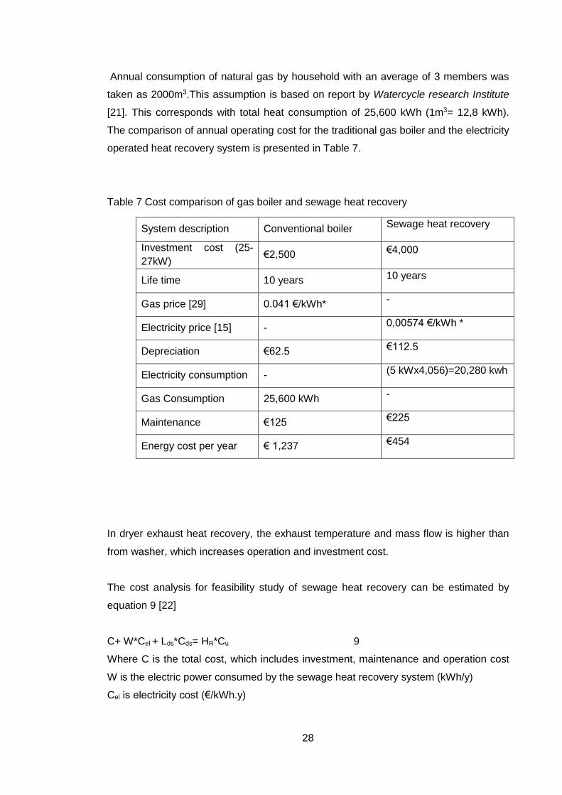
Annual consumption of natural gas by household with an average of 3 members was
taken as 2000m3.This assumption is based on report by Watercycle research Institute
[21]. This corresponds with total heat consumption of 25,600 kWh (1m3= 12,8 kWh).
The comparison of annual operating cost for the traditional gas boiler and the electricity
operated heat recovery system is presented in Table 7.
Table 7 Cost comparison of gas boiler and sewage heat recovery
System description Conventional boiler Sewage heat recovery
Investment cost (25-
27kW) €2,500 €4,000
Life time 10 years 10 years
Gas price [29] 0.041 €/kWh* -
Electricity price [15] - 0,00574 €/kWh *
Depreciation €62.5 €112.5
Electricity consumption - (5 kWx4,056)=20,280 kwh
Gas Consumption 25,600 kWh -
Maintenance €125 €225
Energy cost per year € 1,237 €454
In dryer exhaust heat recovery, the exhaust temperature and mass flow is higher than
from washer, which increases operation and investment cost.
The cost analysis for feasibility study of sewage heat recovery can be estimated by
equation 9 [22]
C+ W*Cel + Lds*Cds= HR*Cu 9
Where C is the total cost, which includes investment, maintenance and operation cost
W is the electric power consumed by the sewage heat recovery system (kWh/y)
Cel is electricity cost (€/kWh.y)

29
Cds is the distribution network cost (€/m)
Lds is the length of distribution network (m)
HR is recovered thermal energy (kWh/y)
Cu is the cost paid by the users (€/kWh.y
With the help of equation 9, the factors having significant impact on cost feasibility can
be estimated. For example, third term on the left hand side, length of distribution net-
work can have overall impact on the cost and the energy recovered. The shorter the
length of network more the system is efficient in terms of cost and energy recovery.
The cost of electricity to operate the sewage heat recovery system is also crucial. It is
important to consider Cu factor too i.e. how we arrange this price, what are the variable
need to be taken into account to mark the price.
Likewise, it is important to calculate net cash flow and benefits of projects for financial
feasibility.
Economic benefit (B) = the mass flow rate of natural gas * price of natural gas
NPV is a powerful indicator of viability of the projects and can be determined from
equation 10 obtained from [2]
NPV =∑ (B − C)i ∗ ai𝑛𝑖=1 10
Where NPV is net present value, B benefit, C is cost which includes cost of heat ex-
changers, installation and auxiliary equipment, cost of pumps, valves, pipes connec-
tions, test, regulations, and transportation and engineering services and a is discount
rate which is obtained by equation 11.
a= 1
(1+𝑖)^𝑝 11; i is interest rate and p is period of month.
13. Pinch analysis
Pinch analysis is a procedure of optimizing heat energy transfer within the processes
with minimum external heating or cooling utilities as possible. For example, power
plant, process industries, pharmaceutical industries practice pinch analysis to optimize
heating and cooling demand and harness waste heat. Pinch analysis utilizes energy
targets, which are ‘absolute thermodynamic targets, showing what the process is in-
herently capable of achieving if heat recovery, heating and cooling systems are correct-
ly designed [23]. The minimum temperature (∆Tmin) difference between hot and cold
composite curves affects the pinch temperature, the required external utilities and the

30
size of heat exchangers [23]. The objective of pinch analysis is increasing efficiency
with minimizing cost.
13.1 Pinch design method comprises of five concepts
I. Targets
The need of amount and size of utilities to be connected in the network are taken as
targets.
II. The pinch
Pinch is a temperature, above which process needs external heating and below needs
cooling. Pinch temperature gives overall idea about the place to locate utilities, how to
recover heat from the processes.
III. More in, more out
An inefficient process requires more than minimum external heating and therefore
more than minimum cooling [24].
IV. Freedom of choice
Within the boundaries of ‘heat sink and source are separate’ we design the plants lay-
outs, control arrangements etc. But violating these limitations not necessarily fulfil the
overall objective.
V. Trade-offs
Pinch analysis is done for optimization solution in maximum energy recovery. This tar-
get can be achieved by minimum number of utility requirement and also by minimizing
the overall cost. The overall cost can be minimized by minimizing number and surface
area of the heat exchanger. Assessing trade-offs can be a way for optimization. For
example, trade-off between energy and surface area, equipment versus low products
purity, more recycle costs versus increased feed use and increased waste, more heat
recovery versus cheaper heat exchanger etc.
Some conditions to consider prior producing minimum utility design.
Heat is not transferred across the pinch
Cold utilities above the pinch and hot utilities below pinch are not allowed.

31
13.2 Design of heat exchangers
This process consists of 3 streams including 1 cold or service water, 1 hot air exhaust
from dryer and a hot wastewater exiting washing machine. ∆Tmin was chosen to be
10oC as rule of thumb. Pinch Analysis was carried out using online tool [25].
Table 8 Cold and hot streams data
Stream
No.
Stream
Type
Ts (oC) Tt (oC) Mass
flow(m)
Kg/s
Cp/kJ/kg.k) Heat
load
Cp(kW/oC)
1 Cold
water
5 40 0.11 4.18 16.093 0.45
2 Hot air 90 34 1.5 1 84 1.5
3 Waste
Water
60 20 0.11 4.18 18.39 0.45
In Table 8, Ts represent the source temperature and Tt represents target temperature
of respective streams. Thermal capacity, represented by Cp, also known as heat ca-
pacity flow rate is temperature independent, which is mass flow time’s specific heat
capacity of the individual stream. Heat load represents the maximum amount of heat
that is being transferred either to or from the system. Source temperatures are ob-
tained on the basis of interview with laundry owner and target temperatures were cho-
sen on the basis of heat exchangers explained in the case study chapter in this thesis
work.
Streams cold water, hot air and wastewater are represented by stream number 1, 2
and 3 respectively. These streams flow in their respective network with temperature
(Ts) and mass flow (m). The aim here is to achieve the target temperature (Tt) by opti-
mizing the heat energy transfer in the process, which include adding of cold or hot utili-
ties in the network. Theoretically, pinch decomposition of the process would appear as
shown schematically in Figure 18

32
Figure 18 schematic of pinch decomposition
The target temperature assumptions are based on temperature performance of Eco-
wec Hybrid Heat exchanger which cools wastewater from 26 oC to 5 oC and preheats
the cold water from 8 oC to 15oC [26]. Similarly, Läckeby air/water heat exchanger cools
air from 120oC to 44.6 oC and heats up water from 10 oC to 34oC [18].
The hot exhaust air is cooled from 90 to 34oC [with reference to VLV heat exchanger,
which cools hot air from 120oC to 44,6oC i.e. reduction approximation is done about
62%]. The wastewater is cooled from 60 oC to 15oC [with reference to EHHE explained
in case studies cools wastewater from 26 to 5oC i.e. reduction approximation is done
about 5 times]. In case of cold or service water, the approximation is done as require-
ment, assuming that hot water requirement is close to 40oC.
Figure 19 and Figure 20 represents the composite curve of cold and hot streams re-
spectively. Table 9 and Table10 represent the enthalpy at respective temperatures
obtained from cold and streams respectively. The cold water is heated from 5 oC to
40oC which gives 2 enthalpies represented by ΔH and can be calculated as (∑Cp,hot-
∑Cp,cold) *(Ti-Ti+1). Where Cp,hot and Cp,cold represents thermal capacities for hot and
cold streams respectively in individual range of Ti and Ti+1. Likewise, enthalpies for hot
streams are calculated in the temperature range cooled from 90-60-40-35 and 20oC.

33
Table 9 CCC data
Figure 19 Cold composite curve (CCC)
Table 10 HCC data
Figure 20 Hot Composite Curve (HCC)
Temperature
(oC)
Enthalpy
(kW)
5,00 86,30
40,00 102,39
Temperature
(oC)
Enthalpy(kW)
20,00 0,00
34,00 6,43
60,00 57,39
90,00 102,39

34
Table 11 represents the output of pinch analysis obtained from online tool [25]. The
result illustrates that pinch temperature is 90oC and 86.3 kW of cooling utility is required
to be placed on the hot stream.
Table 11 CCC curve
Table 12 GCC data
Figure 22 Grand Composite Curve (GCC)
DTmin 10oC
Pinch Temperature 90oC
Ideal Min. Cooling Required 86.3 (kW)
Ideal Min. Heating Required 0.00
Temperature(oC) Enthalpy(kW)
15.00 86.30
20.00 8.85E+1
34.00 8.85E+1
50.00 64.59
60.00 45.00
90.00 0.00
Figure 18 Combined Composite Curve (CCC)

35
The grand composite curve (GCC) gives us the information about the pinch tempera-
ture, minimum heating and cooling utilities and process to process heat integration.
Above the pinch is heat sink and below is the heat source. In this process all the region
falls below the pinch, hence heat source is available lacking heat sink, which is the
information obtained from GCC in Figure 22.
From Figure 22 intersection point of vertical axis and the curve is at 90oC, which is the
pinch temperature. Since curve cannot be observed above the intersection point which
illustrates that no hot utilities are needed. Observing at the bottom (marked by red line)
of the curve, 86.30 kW of cooling utility needs to be added on hot streams, while no
hot utility needs to be added. All the streams in process lie below the pinch. The area
enclosed by green colour below the pinch is the process to process heat transfer. GCC
for streams is summarized in Table 13.
Table 13 Streams availability in GCC
Cold stream Hot stream
Above Pinch NA NA
Below Pinch A A
NA-Not Available
A-Available
GCC for utilities is summarized in Table 14.
Table 14 Utilities above and below pinch in streams
Cold utilities/hot utilities
Above
Pinch
None of the streams are available above pinch.
Below
Pinch
We can’t add hot utilities below pinch but we can add cold utilities below
pinch (on hot streams)

36
Figure 23 Stream matching
Figure 23 represents streams and their matching relationship with red colour as hot
and blue one as cold stream
13.3 Drawbacks of the analysis
In the process, pinch temperature is 900C and cold stream doesn’t fall in this range with
only one hot stream in the range. Table 13 Streams availability in GCC suggests, none
of the streams are available above pinch hence it is not possible to locate hot utilities
above the pinch. Limitations are applied with only option to add cold utilities below
pinch on hot streams.
14. Result
Feasibility study of waste heat recovery from wastewater exiting washing machines
and dryer exhaust air in laundry facility was performed. The results of this thesis project
from respective chapters are presented below.
Heat exchangers, their design parameters and applications were studied and summa-
rized in Table 15. This study helps to select heat exchanger adhering to requirements
of this project. Theoretically, shell-and-tube heat exchanger, finned tube heat exchang-
er, concentric tube heat exchanger and plate heat exchanger were considered suitable
for heat recovery from laundry facility. These heat exchangers’ best operate within
temperature range from 0-120oC. Most importantly these heat exchangers are suitable

37
for both gas-liquid and liquid-liquid working substances i.e. suitable for dryer exhaust
and wastewater exiting washing machine.
Calculations for energy available in wastewater, dryer exhaust and saving by harness-
ing the energy, was performed from the available data. It was found that 103 and 547
MWh of energy is available in wastewater and dryer exhaust air per year respectively.
Furthermore, calculation illustrates that tentatively 6,371 € from waste water and ap-
proximately 33,837 € from dryer exhaust can be saved per year.
For feasibility study, the distance between consumer and heat recovery system, acces-
sibility, flow rate, quality of heat source, upgrading need, legislations and compatibility
with demand were accessed. It was observed that distance between consumer and
recovery system should be as minimum as possible. Approximately 1-5 m2 of space is
necessary to install the system with no allowed major renovation and modification in
existing building. Flow rate, quality of heat source and compatibility are correlated, and
have significant impact on energy output for both wastewater and dryer exhaust air.
Two commercially available heat exchangers Ecowec hybrid heat exchanger (EHHE)
by Wasenco and air/water heat exchanger model VLV by Läckeby were analysed, one
for wastewater and another for dryer exhaust. It was found that EHHE is suitable for
both systems; wastewater and dryer exhaust, meanwhile, later one is suitable for dryer
exhaust only with little variation in design parameters.
Comparison of investment, operation and maintenance cost for sewage heat recovery
by heat exchanger and traditional boiler operating with natural gas was made. The re-
sult showed that, with the present values of natural gas and electricity price, annual
operating cost for sewage heat recovery seems to be higher than conventional gas
boiler for water heating purpose only.
Finally, pinch analysis was performed in order to optimize energy transfer within the
process. Analysis showed that with both the hot and the cold streams available only
below pinch temperature (90oC), 86.3 kW of cooling utility needs to be added on hot
streams, while no hot utility needs to be added.
The values used in calculations for different factors such as mass flow rates and inlet
temperatures of service water were based on previous measurement and interview
with laundry owner. These values and assumptions might cause deviation in energy

38
output. Similarly, the annual operating cost for sewage heat recovery system and tradi-
tional natural gas boiler might vary depending on energy prices and investment cost.
15. Conclusions
The purpose of this thesis was to study the usefulness of waste heat drained away in
wastewater and dryer exhaust. The feasibility study suggests that a significant amount
of energy is available in wastewater and dryer exhaust air that can be harnessed. Ten-
tatively 650 MWh of energy can be recovered from both wastewater and dryer exhaust
air saving approximately € 40,000 per year. Harnessing this energy per year is a com-
pelling benefit for climate and environment. With the current price of electricity and nat-
ural gas the annual operating cost for sewage heat recovery system is significantly less
than traditional gas boiler. Models presented in this project for net cash flow and bene-
fits and cost analysis in this thesis are useful for heat recovery from both wastewater
and dryer exhaust air, when all the relevant figures such as distribution network length
and cost, electricity price, recovered thermal energy are available.
In terms of maintaining minimum distance, accessibility and legislation, the project is
feasible with further need for considerations in flow rate, quality of heat and compatibil-
ity because of their correlations.
Commercially available heat exchangers suitable for this project were presented. The
case studies conferred in this thesis can provide guidance in selecting heat exchangers
for small-scale recovery system. Furthermore, energy optimization within process
needs intensive evaluation due to presence of unequal number of streams and approx-
imated target temperature and flow rates.
The experimental observations within the process for parameters such as temperature,
mass flow could lead to more reliable and accurate energy output and savings. The
heat pump in series at colder exhaust of heat exchanger to heat the water further as
shown in Figure 17 Upgrading possibilities using heat pump and heat exchanger is
recommended for further research. This integration of heat pump and heat exchanger
might harness more overall energy from the process than an individual system.

39
References
[1] Helppolainen J., Ecowec hybrid heat exchanger information, [Internet,
email].Message to Prakash Adhikari. December 21, 2016 [cited 23 December 2016]
[2] Pulat E., Etemoglu A.B., Can M., 2009, Waste-heat recovery potential in Turkish
textile industry: Case study for city of bursa. ScienceDirect,[e-journal] 13(3), pp.663-
672. http://dx.doi.org/10.1016/j.rser.2007.10.002
[3] Liu L., Fu L., Jiang Y., 2010, application of an exhaust heat recovery system for
domestic hot water. Science direct, [e-journal] 35(3), pp. 1476-
1481.http://dx.doi.org/10.1016/j.energy.2009.12.004
[4] O. Chulha et al., 2015. Heat exchanger applications in wastewater source heat
pumps for buildings: A key review. Elsevier, [e-journal], 104. pp.215-232.
http://dx.doi.org/10.1016/j.enbuild.2015.07.013
[5] Alnahhal S. and Spremberg E., 2016,Contribution to Exemplary In-house
Wastewater Heat Recovery in Berlin, ScienceDirect,[e-journal]40,pp.35-40.
http://dx.doi.org/10.1016/j.procir.2016.01.046
[6] Smith et al., 2014.Harnessing Dorm Dryer Heat. [Pdf] Available at <
https://www.rit.edu/affiliate> [Accessed on 20 December 2016]
[7] Baggett, John, Javon Campbell, Richard Lamothe, and Ryan Oppel. 2011,Heat Ex-
tractor. n.p., [Online]. <http://myweb.wit.edu/campbellj/Microsoft%20Word%20-
%20ReportTemplate429.pdf>.[Accessed 13 December 2016]
[8] Mangle_ (machine). (n.d.). In Wikipedia. Accessed 5 December 2016, from
https://en.wikipedia.org/wiki/Mangle_(machine)
[9] Cengel Y. A., Cimbala J.M., Turner, R. H., 2012.Fundamental of Thermal-Fluid Sci-
ences, 2nd ed. New York: McGraw-Hill
[10] Shah R. K., Sekulic D. P., 2003.Fundamentals of Heat Exchanger Design, Hobo-
ken:John Wiley & Sons Inc.

40
[11] Asadi M., Ramin H. K., 2013, Analysis of heat transfer arising radiation in circular
finned-tube heat exchanger. International Journal of Transport Economics,[E-journal]
1(1),pp.1-13. <https://www.researchgate.net/publication/>
[12] JIAWEI, 2013.Brazed Plate Heat Exchanger Feature. [Online]Available at: <
http://www.jiawei-phe.com/Brazed-Plate-Heat-Exchanger.html > [Accessed 2 Decem-
ber 1016]
[13] ThermalDrain, n.d., A Unique Drain Water Heat Exchange Technology, retrieved
from < http://ecoinnovation.ca/technicalguide/> [Accessed 5 December 2016]
[14] Department of Energy, Mines and Resources, n.d. Waste Heat Recov-
ery.[Pdf]Ontario. Available at <www.nrcan.gc.ca> [Accessed 6 December 2016]
[15] HELEN, 2017. District heating price list. [pdf]Helsinki: HELEN. Available at
https://www.helen.fi/en/heating/companies/prices/ [Accessed on 11 January, 2017]
[16] Wasenco, n.d. Wasenco Brochure.[pdf]Wasenco. Available at
http://wasenco.com/en/downloads/ [Accessed 23 December 2016]
[17] Paul bendt, Ecos, 2010. Are We Missing Energy Savings in clothes Dry-
ers?.[Pdf]ACEEE Summer Study on energy Efficiency in Buildings. Available
at<http://aceee.org/files/proceedings/2010/data/papers/2206.pdf> [Accessed 19 De-
cember 2016]
[18] LÄCKEBY,n.d. Heat exchanger air/water.[Online] Available at <
http://lackebyproducts.com/luftvatten/> [Accessed 10 October 2016]
[19] Finlex, 2008. Finnish Land Use and Building Act.[Online]Helsinki: Finnish Ministry
of Justice. Available at < http://www.finlex.fi/fi/laki/alkup/2008/20081129 > [Accessed
23 December 2016]
[20] Hakal K., 2016.District heating prices go wild in Finland. luke.fi/en/blog, [blog],
January 27, Available at :< https://www.luke.fi/en/blog/district-heating-prices-go-wild-in-
finland/ > [Accessed 22 December 2016]

41
[21] Watercycle Research Institute. 2014. Feasibility of small scale heat recovery from
sewers. [pdf] Nieuwegein: KWR. Available at <
https://www.wetsus.nl/websites/wetsus.nl/mediadepot/29128bc9e1a2.pdf > [Accessed
on 10 December 2016]
[22] Fiore S.,Genon G., 2014.Heat Recovery from Municipal waste water: Evaluation
and Proposal. Environmental Engineering and Management Journal, 13(7), pp.1595-
1604
[23] Barnes S., 2013, Using Pinch Analysis to Optimize the Heat Exchange Network of
Regenerative rankine Cycle for an Existing Modern Nuclear Power Plant. Rensselaer
Polytechnic Institute,[pdf]Available at:<
http://www.ewp.rpi.edu/hartford/~gutiee/SPR/Barnes-FinalReport.pdf > [Accessed 25
December 2016]
[24] Lindedahl K., 2016.Pinch Design Method, Industrial Waste Treatment and Recy-
cling TG00AB85-3002.Helsinki Metropolia University of Applied Sciences. Unpublished
[25] Umbach J.S., 2010, Pinch Analysis Tool, [Online] Available at < http://www.uic-
che.org/pinch/stream_input.php > [Accessed December 26, 2016]
[26] Perackova J.,Podobekova V., 2013. Utilization of heat from sew-
age.[Pdf]Bratislava: Slovak University of Technology. Available at :<
http://www.bud.pcz.czest.pl/attachment/id/563> [Accessed on 7 December 2016]
[27] Langley B., 2012.Heat Pump Technology, 3rd ed. Ohio: Prentice Hall
[28] Shell and tube heat exchanger.2016. In Wikipedia. Retrieved on 13 December
2016 from <https://en.wikipedia.org/wiki/Shell_and_tube_heat_exchanger>
[29] STATISTICAL OFFICE OF THE EUROPEAN COMMUNITIES. (1990). EURO-
STAT: Regional statistics. Electricity price for Domestic consumers (2016). Luxem-
bourg, Eurostat. Retrieved from < appsso.eurostat.ec.europa.eu > [Accessed on 10
December 2016]