Feasibility study and supplement : demonstration mine ...
156
FEASIBILITY STUDY AND SUPPLEMENT DEMONSTRATION MINE USING LONGWALL MINING TECHNIQUES WINDBER / SOMERSET COUNTY / PENNSYLVANIA r oG- , U.S. DEPARTMENT OF COMMERCE ECONOMIC DEVELOPMENT ADMINISTRATION
Transcript of Feasibility study and supplement : demonstration mine ...

FEASIBILITY STUDY AND SUPPLEMENT
DEMONSTRATION MINEUSING
LONGWALL
MINING TECHNIQUESWINDBER / SOMERSET COUNTY / PENNSYLVANIA
r oG- ,
U.S. DEPARTMENT OF COMMERCEECONOMIC DEVELOPMENT ADMINISTRATION


FEASIBILITY STUDY AND SUPPLEMENT
DEMONSTRATION MINE
USING
LONGWALL
MINING TECHNIQUES
WINDBER / SOMERSET COUNTY / PENNSYLVANIA
1966
U.S. DEPARTMENT OF COMMERCEJOHN T. CONNOR, Secretary
Eugene P. Foley, Assistant Secretary
and Director of Economic Development


FOREWORD
Renewed interest in the 60-year-old longwall method of coal
mining stems from the recent development of moveable, hydraulic
roof supports.
This study of experience with longwall mining techniques in a
demonstration mine in Pennsylvania was prepared under contract
by Allison L. Bayles and Associates for the Economic Development
Administration's predecessor agency. The study is being
published because --
-- it covers economic aspects of longwall mining not
normally found in the writings of engineers and
geologists
;
-- it will be a valuable tool for libraries, schools
of mining, and industrial consulting firms;
-- it will be of signal interest to the main industry
in this country's number one redevelopment region,
Appalachia.
Eugene P. Foley
Assistant Secretary of Commerceand Director of Economic Development
ALLISON L. BAYLES 8 ASSOCIATES
CONSULTING ENGINEERS
TSBURGH, PEN
Mr. Frank A. CirilloChief, Technical Projects DivisionArea Redevelopment AdministrationU. S. Department of CommerceWashington, D. C. 20230
14 October 1964
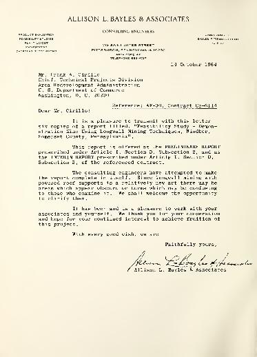
Reference: AF-30, Contract Cc-6114Dear Mr. Cirillo:
It is a pleasure to transmit with this lettersix copies of a report titled, "Feasibility Study - Demon-stration Mine Using Longwall Mining Techniques, Windber,Somerset County, Pennsylvania".
This report is offered as the PRELIMINARY REPORTprescribed under Article I, Section D, Subsection 2, and asthe INTERIM REPORT prescribed under Article I, Section D,
Subsection 3, of the referenced contract.
The consulting engineers have attempted to makethe report complete in itself. Since longwall mining withpowered roof supports is a relatively new art there may beareas which appear obscure or terms which may be confusingto those who examine it. We shall welcome the opportunityto clarify them.
It has been and is a pleasure to work with yourassociates and yourself. We thank you for your cooperationand hope for your continued interest to achieve fruition ofthis project.
With every good wish, we are
Faithfully yours,
Associates

ALLISON L. BAYLES 8 ASSOCIATES
CONSULTING ENGINEERS
8 June 196 5
Mr. Frank A. Cirillo, ChiefTechnical Projects DivisionOffice of Program DevelopmentArea Redevelopment AdministrationU. S. Department of CommerceWashington 25, D. C.
Reference: AF-30, Contract Cc-6114
Dear Mr. Cirillo:
It is a pleasure to receive your letter of 4 June1965, advising us that our report titled, "Feasibility Study-Demonstration Mine Using Longwall Mining Techniques, Windber,Somerset County, Pennsylvania", transmitted with our letterof 14 October 1964, and the Supplement to the FeasibilityStudy, transmitted with our letter of 1 April 1965, are accept-able as the complete report required under the subject contract.Accordingly, we have incorporated the substance of the fore-going two papers into one report which is transmitted with thisletter
.
We devoutly wish that this study should result inan effective improvement in the economic conditions of SomersetCounty and shall continue our efforts toward this end.
It has continued to be a pleasure to work with yourassociates and yourself. We thank you for your cooperation.We shall hope for your continued interest, and we commend theAdministration on its foresight in making such studies possiblefor the benefit of our citizenry.
With every good wish, we are
Faithfully yours,
/^-^<^X~^Allison L. Bayles & Associates
Digitized by the Internet Archive
in 2012 with funding from
LYRASIS Members and Sloan Foundation
http://archive.org/details/feasibilitystudyOOalli
Page
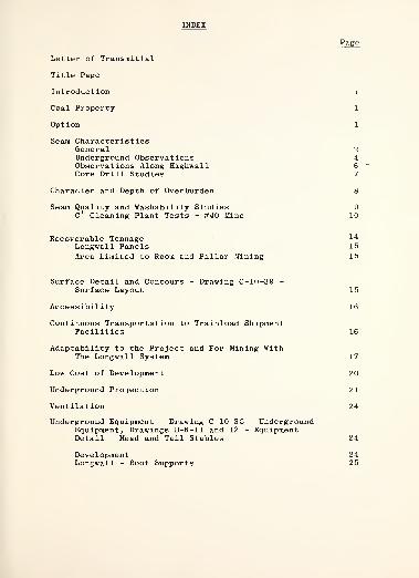
Letter of Transmittal
Title Page
Introduction i
Coal Property 1
Option 1
Seam CharacteristicsGeneral 2Underground Observations 4Observations Along Highwall 6Core Drill Studies 7
Character and Depth of Overburden 8
Seam Quality and Washability Studies 9C
T
Cleaning Plant Tests - #40 Mine 10
Recoverable Tonnage 14
Longwall Panels 15
Area Limited to Room and Pillar Mining 15
Surface Detail and Contours - Drawing C-10-39 -
Surface Layout 15
Accessibility 16
Continuous Transportation to Trainload ShipmentFacilities 16
Adaptability to the Project and For Mining WithThe Longwall System 17
Low Cost of Development 20
Underground Projection 21
Ventilation 24
Underground Equipment - Drawing C-10-3 5 - UndergroundEquipment, Drawings B-6-11 and 12 - EquipmentDetail - Head and Tail Stables 24
Development 24Longwall - Roof Supports 25
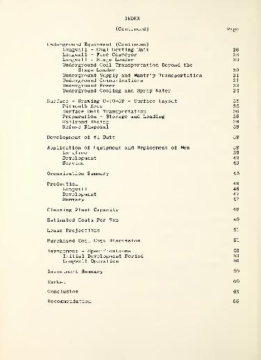
INDEX
(Continued) PjM?G
Underground Equipment (Continued)Longwall - Coal Getting Unit 26Longwall - Face Conveyor 28Longwall - Stage Loader 30Underground Coal Transportation Beyond the
Stage Loader 30Underground Supply and Mantrip Transportation 31Underground Communications 31Underground Power 32Underground Cooling and Spray Water 34
Surface - Drawing C-10-39 - Surface Layout 35Pitmouth Area 35Surface Belt Transportation 36Preparation - Storage and Loading 36Railroad Siding 38Refuse Disposal 39
Development of #1 Butt 39
Application of Equipment and Deployment of Men 39Longface 39Development 42Service 43
Organization Summary 45
Production 46Longwall 46Development 47Summary 47
Cleaning Plant Capacity 48
Estimated Costs Per Ton 49
Lease Projections 51
Purchased Coal Cost Discussion 51
Investment - Specifications 53
Initial Development Period 53
Longwall Operation 56
Investment Summary 59
Market 60
Conclusion 63
Recommendation 66

INDEX
(Continued)
Exhibit I - Option
Exhibit II - Report of Analysis of Coal andWashability Studies by WarnerLaboratories, Inc.
Drawings - Proposed Demonstration MineEast of Windber, Pennsylvania
A- 1-32 Right of Way Across McQuaide Surface
B- 6-11 Equipment Detail - Head Stable
B- 6-12 Equipment Detail - Tail Stable
C-10-25 General Flow Diagram
C-10-32 Surface Plant Layout Showing ProposedSiding Extension
C-10-33 Strata and Seam Data
C-10-34 Projection - c' Seam
C-10-35 Underground Equipment
C-10-38 Mining Plan
C-10-39 Surface Layout

Introduction
This report contains the results of a feasibility
study of a projected Demonstration Mine to be located east
of Windber, Pennsylvania on the outskirts of that city. The
idea of such a mine was inspired by the desire to relieve
the depressed condition of the coal industry in Central Penn-
sylvania. The solution seemed to lie in finding and applying
a method of mining the thin seams of the area profitably.
The consulting engineers felt that longwall mining with caving
using powered roof supports might hold the key. It had re-
vitalized the coal mining industry in the United Kingdom in
a relatively short period.
Accordingly, an approach was made to Dr . H. B.
Charmbury, Secretary of the Department of Mines and Minerals
of the Commonwealth of Pennsylvania, to ascertain his reaction.
It was favorable subject to endorsement by the Bureau of Mines.
The latter expressed favorable interest and the Area Redevelop-
ment Administration was approached to ascertain its attitude.
It, too, was receptive.
Preliminary reconnaissance indicated Somerset County
as a location and a property was located east of Windber,
Pennsylvania, which seemed to satisfy conditions. The sponsor-
ship of the Somerset County Development Council and the Commun-
ity Development Council of Windber was sought and granted
heartily by them.
The Area Redevelopment Administration entrusted the
Consulting Engineers with the task of preparing a feasibility
study which would include but not be limited to the following
accomplishments
.
Preliminary Investigation - Study the strata andseam characteristics in adjoining mines and consultwith experienced operators of the same seam in thearea to back up preliminary findings which werelimited to the study of core drill data and highwallobservations. - Take channel samples along the high-wall and have a washability study made to determinethe amount and type of cleaning necessary to meetthe proposed market requirements.
Select the seam and area for the second installationand study the strata and seam characteristics inorder that the face equipment can be designed forboth mining conditions.
1. Obtain options on the surface and coal.
2. Carry through the market survey to assure outletsfor the product of this operation and secure commit-ments for the output
.
3. Make surface surveys, surface and mine layouts,detailed plans and specification for mine, prepara-tion plant, storage and rapid loading facilities,select equipment, prepare a definitive estimate ofcapital expenditures and prepare a projection ofoperating costs.
4. Select a coal company to operate the projectthrough the first and second installations.
5. Prepare progress reports, a preliminary draft,a report on the trip (to the United Kingdom) and afinal report.
6. Inspection of facilities in the United Kingdom.
The work was authorized on 20 December 1963.
The substance of this report which follows purports
to satisfy the foregoing areas of inquiry. Perspective and
depth of judgment have been enhanced by two additional

extended inspection trips to the United Kingdom and Western
Europe by Mr. M. Albert Evans in connection with investiga-
tions on longwall mining techniques and equipment.
The selection of a mining operator has been made,
who has reserves near the first property adequate and suitable
to support a second location. At this stage the project is
being investigated and a plan of financing is being developed.
These aspects do not affect feasibility and are omitted from
this paper.


Coal Property
The area of "C" seam chosen earlier for the initial
operation has been optioned, together with necessary surface,
and has been studied for (1) local seam characteristics, (2)
character and depth of overburden, (3) seam quality and wash-
ability, (4) recoverable tonnage, (5) surface details and contours,
(6) accessibility, (7) transportation to and for trainload ship-
ments, (8) adaptability to the project and for mining with the
longwall technique and (9) low cost of development.
The property adjoins the Borough of Windber on the
surface and underground The Berwind-White Coal Mining Company's
#35 Mine, of which it was originally a part. A sandstone replace-
ment crossing the #35 Mine in a Northeast direction isolated the
coal between this barren strip and the outcrop and made it im-
practical to mine the coal from #35. Otherwise the coal would
have been mined out before this time.
The barren strip maintained a wavy but fairly uniform
line across the #35 Mine, so it is reasonable to assume that the
characteristics of the replacement will be similar on its South-
east side. The area has been core drilled and has also been
exposed on three sides beyond the fault by stripping.
Option
In order to have permission to make a thorough study of
the property and be assured it would be available, an option-lease

was requested from The Wilmore Coal Company, Windber, Pennsylvania
the land company of the property owner, The Berwind -White Coal
Mining Company, Philadelphia, Pennsylvania. We were advised
there would be complete cooperation and to proceed with our
investigation and determine the surface requirements so that the
papers could be prepared. Later, after the surveys were made and
surface needs submitted, our attorney, at the request of Wilmore,
prepared an outline for such a document and, in addition, advised
on general terms for the protection of the lessee. This was com-
pleted and handed to the Wilmore representative, who drew up an
option-lease and presented it to his superiors in Philadelphia.
It was at this late date that the question arose as to whether
any lease was desirable at this time. After a period of better
than two months the problems were finally resolved and a favor-
able option-lease was forwarded for signatures.
The option-lease, extending to October 31, 1964, has
been executed by the Somerset County Development Council and
The Community Development Association of Windber, as lessees,
and The Berwind-White Coal Mining Company, as lessor. The agree-
ment is made to the lessees, or Their Nominee, subject to the
approval of Berwind-White. A copy of the option-lease is made a
part of this report as Exhibit I. A request has been made for
an extension to December 31, 1964, and we have some encouragement
that it will be granted.
Seam Characteristics - General
General characteristics of the :
'C ' " seam in the area
were discussed with mining men in the Windber area, including
Mr. D. Edwin Eakins, present superintendent of Vulcan Coal
Company's Mine #40 (old Berwind -White property). He was recom-
mended as one of the best informed men on the "C'
" seam in the
Windber area.
Mr. Eakins advised that around Windber the "C '" seam
conditions are fairly uniform. Entries can be driven twenty feet
wide, but usually are sixteen feet because of equipment limitations.
Rooms are driven 23 to 35 feet wide. In both instances, the
characteristic bone and rash over the coal can normally be held
when the coal is extracted with a continuous miner. The coal
seam is not grown into the bone and rash and Is free from them.
Normal room centers are 60 feet> and In removing the
pillars the rash does not crumble. In establishing a butt entry
pillar line, the first fall comes at a maximum distance of
approximately 150 feet. The roof is fairly easy to control, even
under thin cover. Roof conditions would be normal 100 feet inby
a highwall, or 70 feet of cover.
The seam floor is normally hard, but will soften with
water. There is little water following pillar falls. However,
the seam dips uniformly with very few rolls so that water does
not lay in swags. For these reasons, it is not difficult to
project for gravity flow away from most of the work.
The seam thickness is fairly uniform, varying gradually
over an extended area. The coal is of a soft nature and hardness
increases with the percentage of impurities. Therefore, the plus
3/4 inch coal is higher in ash and sulphur. Rejects are heavy
with sulphur and fire rapidly.
-3-

The conditions combine to make high production possible
with the continuous mining type of equipment. Mr. Eakins has
records (not averages) up to 875 tons of raw coal, or 500 tons of
clean coal where the rash was mined in a full seam continuous
miner operation.
Seam Characteristics - Underground Observations
The unmined pillars of the #35 Mine are being retreated
by the Dell Coal Company. This operation, as stated above, is
separated from the proposed area by only a sandstone replacement
of about 2,500 feet in width. Therefore, conditions should be
similar, and for that reason the mine was visited and underground
details studied carefully.
Pillars have been retreated to 5 Right Butt entry, which
allowed a substantial area of standing pillars for observation.
There were very few falls in the first mining of some years ago,
even though rooms are wide (50') and room pillars comparatively
narrow (30' ), timbering skimpy and rotted out. Entries had been
driven 12 feet wide and the full seam taken, but the rash had been
left in place in roomnecks and rooms. The bone had been taken
with the coal. The rash had caved in these narrow (12 ') roomnecks,
but was intact in the wide rooms. The reason is possibly due to
more concentrated coal blasting effects in the narrow work.
The seam in gradient and thickness was fairly uniform,
dipping at about 2% to the Northwest and varying gradually in
thickness from 45 to 60 inches. The rash and bone were fairly
consistent at about 12 inches and one inch, respectively, except
in one small area it was noted that the rash had turned into rock.

When the sandstone replacement was encountered it was
abrupt, with the seam dropping to a few inches in a matter of ten
feet or so. The line of this replacement had a wavy nature but
was consistent in direction.
The bottom was hard with the exception of a few places
where it was wet. Water flows away from the remaining pillars
by gravity and very little was observed.
The roof above the coal is a strong shale and remains
good even with as low as 50 feet of cover. No evidence in either
appearance or behavior could be seen in the roof or bottom from
mined out "B" seam 100 feet below. The operators were not ex-
periencing any problems from this source.
The second mining was being done with undercutting and
shooting, with holes extended into the bone so as to bring down
the rash, and then hand loaded. The entry pillars and room
stumps were recovered by driving through lengthwise and slabbing
back. This left about eight feet of coal. The room pillars were
recovered by further widening the 50 foot rooms until all but
about ten feet were removed. The caves appeared to be weight-
relieving.
The roof has to have unusually high tensile strength to
permit wide expanses to stand for so long after first mining and
then be submitted to this method of pillar recovery. This is
recognized; therefore, the weight-relieving falls with partial
mining under this strong roof can only be explained in that the
"B" seam caving has resulted in incipient fractures forming in
the upper measures.
It was noted in rooms at the edge of pillar caves that
-5-

posts broke without breaking the rash over them. The rash, how-
ever, showed cracks in a few places.
Coal cleats are not strong and are on an angle to the
horizontal rather than vertical planes. Again, the latter may be
due to "B" seam mining.
The seam contained a bone parting about 30 inches from
the bottom. This and the rash and top bone were being loaded,
picking out some of the top rock. The resultant raw product
was in excess of 9# ash, but the operators felt that by selective
mining they could hold 9& without cleaning. The mine is non gaseous.
Seam Characteristics - Observations Along Highwall
The proposed area has been stripped on three sides,
exposing the seam and the strata which would make up the shelf in
a longwall operation. An 800 foot length on the East side was not
stripped because of a hard bed of sandy shale at that location.
The highwall was studied in detail. The bottom had
remained hard after exposure to the elements for a year or more.
There was very little sluffing of the seam or measures above from
oxidation and no fall-outs of any consequence. The seam had a
uniform dip with no rolls and maintained a reasonably uniform
thickness varying from 43 to 49 inches. The bone near the middle
of the seam changed from 3/8 inch to two thin partings totaling
two inches to a thickness of five inches.
The top bone also changed in thickness from 3/4 inch to
five inches, but the increase usually resulted in a reduction of
thickness of rash.
The strata over the coal were bedded and fissured.
-6-

The latter could have come from blasting or from the mining of
the "B" seam. At one location a relatively recent normal fault
with a three-inch offset showed up in the coal, definitely due
to "B" seam mining.
Mr. Franklin Miller, Mining Engineer for Berwind -White
Coal Mining Company, has assured that mining in the "B" seam has
been clean. In the later mining of the "C'
" seam the only ill
effects encountered were in passing over barrier and chain
pillars which had been left in the "B" seam for a purpose.
Seam Characteristics - Core Drill Studies
A total of six core drill records of the strata and
coal with analyses of the seam and five core drill records of
the seam only with analyses were made available by the Wilmore
Coal Company.
This information, together with highwall sections and
analyses made at a later date, are shown in section on Drawing
C-lO-33 - Strata and Seam Data, a part of this report. The
highwall sections are limited to 2,400 feet along the Southeastern
side, due to some backfilling which took place between the first
study and the time of the measurements. The backfilling has
been discontinued.
The core drilling and prospect records of seam and
strata, illustrated in Drawing C-lO-33 - Strata and Seam Data,
assure a continuity of normal "C" mining conditions, other than
the small area in the Southeast in and around the locations where
stripping was discontinued. They disclose natural bed separations.
Good longwall practice under conditions in the Appalachian Field
-7-
requires that the beds to be caved be at least three times the
thickness of the seam to be removed. In certain areas it may be
necessary to go as high as 27 feet above the seam to reach a
normal bedding plane meeting the above conditions.
The core drilling further discloses that the seam
thickness will range from 43 Inches to 48 inches with little
variation in the analysis of the coal below the bone. Selective
mining would produce a raw product of approximately 10$ ash. The
bottom is strong.
An effort was made to determine the normal caving height
in the initial fall when starting off new pillar lines as an
assist In determining expected shelf thickness for longwall mining.
This was not available, but it was determined that the first cave
occurred at a maximum of 140 feet on a 240 foot face. If we
assume that the sandy shale, common to the area, has a tensile
strength half-way between a strong and weak sandstone, then,
using this in calculating the thickness of the breaking strata by
the fixed beam formula, we determine the thickness at a maximum
of 25 feet. This is close to the 27 feet determined from the core
drilling as the thickest natural beam section.
Character and Depth of Overburden
The strata along the highwall were relatively thin
bedded, but the core drilling indicates a definite change toward
thick sandy shale to the North. This would give concern under
the extremely light cover if it were not for the fracturing which
has taken place following the mining of the "B" seam. Core drilling
can only show trends. However, the good pillaring conditions normal
to the "C'
" do indicate that, while the strata are strong, they have

a bedded characteristic which assists in caving.
By transposing enlarged geologic survey maps, depth of
cover has been determined as 220 feet maximum.
At 90 feet above the "C 1 " seam, the "E" seam is being
stripped, and much of the area can be stripped, indicating that
most of the cover does not exceed 150 feet.
A survey was made along a small stream bed at the South-
west end of the property to determine definitely the cover along
that stream. This influenced the projection of the first panel.
Elsewhere, water courses are so small that they have no significance.
Seam Quality and Washabllity Studies
The bone parting in the seam brings the ash content to
10$ even with selective mining. Therefore, some cleaning will be
necessary.
Cleaning plant records from Berwind #40, "C'
" seam,
were made available by The Berwind -White Coal Mining Company.
These covered daily data from November 1959 through September i960,
and special tests during 1958 for mining under the bone, full seam
mining with Joy Continuous Miner and full seam mining with a
bottom cutter. A summary of these tests is displayed on Page 10.
The cleaning facilities included hand picking the plus
5", washing the 5" x 1/2" in a Chance Cone, washing the 1/2" x 1/4"
in a Hydrotator, air cleaning the 1/4" x 0. The 1/4" x 14 Mesh
middlings from the air tables were recleaned in the Hydrotator
and the 14 Mesh x in a Classifier. The 2 mm size from the
Hydrotator was also cleaned in the Classifier.
The air tables did a good job, reducing a raw product

iH. C7\ OOJ HHrl| H
om>- moot- ml .
rH^t rH
00 00 001 I
C--t-Ot-N|
rH
rHVO O^t rHrHrHI rH
O 0^ OJ rH-=* o
OOO OlHHM OS
CO-=fOJ
cooo m t~-
LP\00ooo
oo mC-ON
00 tr~0\OJ OJ CM OJ
oo ctn mm oococol oo
CO CTMCOO MC~- CT\to O \D
inm t-0>a\oo
rHOOCO on
OJ t-OI <orH OJ rH rH
COUDtxJo rH Jt C0VO LT>LT\ oo" CO 001 00
^f COlOJ OCOI-=f^rpo O
oo
co rH om mH rHVJD o in
r<~«- VO^T t-HO| ONrHon U3VO c?\ t-M h-
00 C-- -=t m t>-tr~t^\ t-
tSOOSt)O CQ O CC «
CD ii <# X ct3CO >OHrt -h B-HCUd) Ph g Ol, .
fc o h o rHo o CD O to O
•Hen c c-i c oSHwmp «J CI) crt <u oO CD CO (1) nH XXXJh H CO
•DOC note t. pq pq pq
gaidrP 3 r
0J X :
-P fc D-rHO CD O c3
fflCBO•H O
m s c<«-i o„ ctJ c3
CDSv OC O COP T3OrH hC 0)
O K C CD P- rl C C OJA ou
CU-nUrH 03C C ^O TjffJOrllO'rid)C T> TJ O C 3 C C
S2 CW c3 O t=> J
CD OS rH I
h oj cn=r irwo

ranging from 11. 52$ to 12. 31$ ash and 2.46$ to 2.29$ sulphur to
ranges of 9.2$ to 8.46# ash and 1.57$ to 1.18$ sulphur. However,
It was quite evident from the difference in analyses between raw
product and core drill and channel samples that, as is normal,
the mobile loaders and continuous miners were contaminating the
product with top and bottom. The analyses obtained with hand
loading at Dell Coal Co. verified this.
The longwall shearer working from the top of the face
conveyor pan line, on the other hand, is easier to control.
Mining being limited to the coal rather than taking the full seam
also would change conditions. Further, the seam changes in itself
over a distance.
In light of this, careful channel samples were taken
along the exposed highwall, covering a distance of about 3*200
feet, to determine what could be expected by mining the coal seam
only. The coal was all crushed to go through J,/k inch round holes,
the minus 20 Mesh removed (An air plant gives little or no clean-
ing to minus 20 Mesh except for heavy sulphur), and a float and
sink study made at 1.60 gravity, an air plant cleaning limit.
The float plus 20 Mesh product and raw minus 20 Mesh were com-
bined and a complete analysis made. Warner Laboratories, Inc.,
Cresson, Pennsylvania, performed the washability studies. Their
report is appended as Exhibit II. A summary follows:

Plus 20 Mesh Raw Minus 20 Mesh Raw% % Ash % Sul . W % Ash % Sul .
Top Rash _ n nn r-„ ^ c 10.25 2.34Top Bone 20 -° 20 -59 3-60 1?<9g x> §6
Seam to be rained 87.6 9.92 2.15 12.4 8.29 2. 30
Plus 20 MeshFloat at 1.50 Sink at 1.60
% Ash % Sul. % Ash % Sul.
T?p Bone 73-2 - 9.5 2.29 26.8 - 50.88 7. 18
Portion of Seamto be mined 94.47 7-71 1.01 5.53 ^7.57 21.61
Portion of Seam to be Mined - Composite of Plus 20 Mesh Floatand Minus 20 Mesh Raw
AS Received Dry Basis
% Moisture% Volatile Matter% Fixed Carbon% Ash
O.9815.5775.637.82
100.00
15.7276.387.90
100.00
% SulphurB.t.u.B.t.u. (Moisture & Ash Free)
1.2014,160
1.2114,30015,527
Fusing Temperature of Ash 2780° F
Coke Button Index A.S.T.M. No. 3i
Grindability (Hardgrove Index) 103
The coke button results should be ignored as the coal had beenexposed to the weather for some time.
The screening results show an exceptionally high per-
centage of the plus 20 Mesh material available for cleaning and
indicates that satisfactory results can be obtained by cleaning
with air tables, if mining is limited to the portion of the seam
below the rash and top bone. The coal will have to be crushed to
3/4 inch as a maximum for this type of equipment. To simplify
-12-
crushing and screening and at the same time remove some of the
bone parting and sulphur lenses without crushing, a Bradford
Breaker with 3/4 inch round holes is proposed for installation
ahead of the air cleaning units.
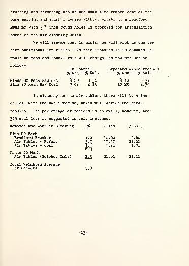
We will assume that in mining we will pick up one per
cent additional impurities. In this instance it is assumed it
would be rash and bone. This will change the raw product as
follows:In Channel Expected Mined Product
% Ash % Sul . % Ash % Sul .
Minus 20 Mesh Raw Coal 8.29 2.30 8.42 2.34Plus 20 Mesh Raw Coal 9.92 2.15 10.29 2.35
In cleaning in the air tables, there will be a loss
of coal with the table refuse, which will affect the final
results. The percentage of rejects is so small, however, that
30$ coal loss is suggested in this instance.
Removed and Lost in Cleaning % % Ash % Sul.
Plus 20 MeshBradford Breaker 1.0 40.00 3.60Air Tables - Refuse 3.7 47.57 21.61Air Tables - Coal 1.6 7.71 1.01
Minus 20 MeshAir Tables (Sulphur Only) 2^ 21.61 21.61
Total Weighted Averageof Rejects 5.8
-13-

Expected clean coal results from removal of above:
g g Ash
Raw Plus 20 Mesh 100.0Clean Plus 20 Mesh 93.7Combining
Plus 20 Mesh Clean Coal 82.0Minus 20 Mesh Raw Coal 12.4
Reassembled Product 94.4
10.298.55
8.557.79
8.45
% Sul.
2.351.56
1.561.80
1.59
Analysis
AshVolatile MatterFixed Carbon
SulphurB.t.u. (Dry Basis)B.t.u. (Moisture & Ash Free)Fusion Temperature of AshGrindability
% Calculated % Expected
8 4515 6175 94
100 00
8.5015.6075.90
100.00
1.59 1.6014,220 14,200
15,5272500°
103
Recoverable Tonnage
The thickness of the coal has been determined to range
from 43 inches to 48 inches, and two shearer drum sizes best
adapted to the seam have been chosen for the longwall work. One
of these will cut a height of 44 inches and the other 4l inches.,
with an average of 43 inches. The development work, with the
52 inch clearance required in the tail stable, will average
47 inches in height.
It has been determined from the projection, shown on
Drawing C-lO-34 - Projection C ' Seam, and later discussed in
detail, that the shape of the coal reserves permits three longwall
panels, two with 600 foot faces totaling 8,000 feet and one of
which will have an extension for a narrower face (295 feet by
500 feet long); and one 595 foot face 4,000 feet in length.
Revised 5/26/65-14-
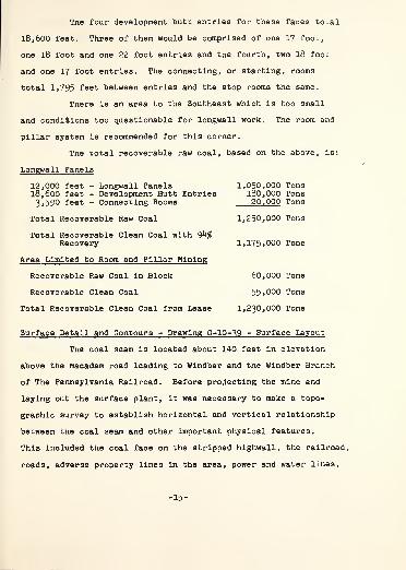
The four development butt entries for these faces total
18,600 feet. Three of them would be comprised of one 17 foot,
one 18 foot and one 22 foot entries and the fourth, two 18 foot
and one 17 foot entries. The connecting, or starting, rooms
total 1,795 feet between entries and the stop rooms the same.
There is an area to the Southeast which is too small
and conditions too questionable for longwall work. The room and
pillar system is recommended for this corner.
The total recoverable raw coal, based on the above, is:
Longwall Panels
12,000 feet - Longwall Panels 1,050,000 Tons18,600 feet - Development Butt Entries 180,000 Tons3,590 feet - Connecting Rooms 20,000 Tons
Total Recoverable Raw Coal 1,250,000 Tons
Total Recoverable Clean Coal with 94$Recovery 1,175,000 Tons
Area Limited to Room and Pillar Mining
Recoverable Raw Coal in Block 60,000 Tons
Recoverable Clean Coal 55,000 Tons
Total Recoverable Clean Coal from Lease 1,230,000 Tons
Surface Detail and Contours - Drawing C-10-^9 - Surface Layout
The coal seam is located about 140 feet in elevation
above the macadam road leading to Windber and the Windber Branch
of The Pennsylvania Railroad. Before projecting the mine and
laying out the surface plant, it was necessary to make a topo-
graphic survey to establish horizontal and vertical relationship
between the coal seam and other important physical features.
This included the coal face on the stripped hlghwall, the railroad,
roads, adverse property lines in the area, power and water lines.
-15-
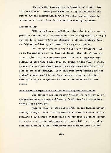
The work was done and the information plotted on 100
foot scale maps. These prints are too bulky to include in the
report but the information derived from them has been used in
preparing the basic data for the various drawings appended.
Accessibility
With regard to accessibility, the objective is a central
point in the area at a location with large siding facilities which
can easily be reached by good highways, a limited distance from
the highway and having a minimum of underground travel.
The proposed property meets all these conditions. It
is in the northern part of Somerset County, the initial opening
within 1,400 feet of a proposed plant site on a large railroad
sidingj is less than a mile from the center of the Town of Windber
by way of a good macadam highway; has only one-half mile of dirt
road to the mine openings. With each butt entry opening off the
highwall, there could be no closer access to the working face.
Drawing C-lO-34 - Projection C ' Seam illustrates most of the
above
.
Continuous Transportation to Trainload Shipment Facilities
The distance and topography between the mine portal and
the preparation, storage and loading facilities lend themselves
to belt transportation.
This is shown in plan and profile on the Surface Layout,
Drawing C-lO-39. Very little gradework will be necessary for in-
stalling a 1,425 foot 30 inch belt conveyor from a loading feeder
bin at the end of the underground belt to an 800 ton surge silo
near the cleaning plant. Transportation distance from the bin
-16-

to the Bradford Breaker and air plant is minimum. The belts
from the air plant to the 4,000 ton storage pile, and from there
to the pantleg chute over double railroad tracks are not minimum
but the distances are relatively short.
The railroad siding was shortened by final terms of
the option-lease, making it necessary to extend the double track
a distance of 1,060 feet (See Drawing C-lO-32 - Surface Plant
Showing Proposed Siding Extension). This anticipated a satis-
factory arrangement for crossing a small surface outstanding
ownership (See Drawing A-l-32 - R-O-W. Across McQuaide Surface).
Otherwise another 150 feet must be added to the siding.
Cross sections for fill determinations and drainage
requirements for the extended siding sub grade were made in order
to get contract prices for the extension.
Adaptability to the Project and For Mining With The Longwall System
The proposed coal property has the necessary reserves
for the two-year period of operation. It is reasonably close to
the railroad siding facilities. The topography is adaptable to
the surface plant requirements. The location is central for
the area and readily accessible for visitors. The coal is
inherently a good utility fuel and can be cleaned with a minimum
of investment and loss in refuse. The largest reserves in Somerset
County are in the "C 1 " seam. The seam thickness to be mined is
close to the average of Central Pennsylvania coal reserves to be
mined in the next decade. The seam has ideal conditions for high
-17-

productivity with a continuous type loading machine. Finally,
opening the mine and getting into production can be accomplished
with minimum cost.
Strata and seam conditions are favorable for the long-
wall system of mining. The bottom is firm and without undulations.
The rash is strong and should act as a cushion against shock
when resetting the supports after advancement. There is a
question, however, as to whether or not the bone between the coal
and the rash can be held when the head coal, which will act as a
mat, gets as thin as an inch or so. Should that problem develop,
there are two solutions: (l) raise the seam horizon and cut out
the bone or (2) maintain the horizon by getting a larger cutting
drum and, if necessary, extensions for the support legs.
The roof is strong but caveable with weight-relieving
falls. Mining and caving of the "B" seam, 100 feet below, have
caused the formation of incipient cleavage planes in the strata
above the "C" seam which will offset the expected lack of abut-
ment pressure fractures due to limited cover.
Shelf thickness, calculated from initial caving informa-
tion and by the fixed beam formula, using a maximum span of 150
feet with a width of 240 feet, is determined to be between 19 and
20 feet. An ultimate strength of 600 pounds per square inch was
used for the roof material. While the roof is strong, this
figure probably is high, as was anticipated earlier in this
report and is borne out by core drill records showing as high as
27 feet to the first normal bed separation above three times the
seam thickness.
Using the 27 feet as the expected maximum shelf thickness
-18-

and a shelf length of 19.7 feet, which anticipates a cave with
each support advance and a 60 degree roof fracture, then assuming
the shelf to be a supported cantilever, by the Theorem of Three
Moments a support having a yield strength of 49 tons per lineal
foot is required. Of this, 80$, or 39 tons per lineal foot, must
be located in the waste edge support (middle and rear legs).
Should the assumption that a cave will occur with each support
advance be wrong and a cave comes only with every second advance
of the supports, then the shelf length would be 21.9 feet, re-
quiring 60 tons per lineal foot, or approximately 48 tons per
foot of waste edge support per lineal foot of face.
Standard powered supports for the latter severe yield
requirements are available in the seam range desired.
There was a successful longwall operation in the 'C'"
seam a few miles from the proposed site during the 1920 's. A
waste edge support of 50 tons per foot of face was used, but no
records are available to determine whether or not that support
intensity was ever needed. The stronger base support now available
would reduce the per foot requirements of the earlier rigid jacks-
set on wood sills.
The variable consist of the top rash and bone, as well
as the high ash of the float 1.60 of this portion of the seam
even under normal conditions, makes it most desirable to limit
mining to the portion of the seam under the top bone. Below
this is a parting of bone about a foot from the top bone and
sulphur lenses to be removed in cleaning.
Seam conditions are satisfactory for mining with either
a plough or a positive action type longwall continuous machine.
-19-
A plough would mean more contamination of the coal, particularly
from the top bone. Also, encouraging roof pressure to increase
loadability might also bring down the rash. Most Important, It
is the intent to prove equipment which could be used in many
seams rather than a special condition. Therefore, a positive
action coal getting unit is most desirable. There is a variation
in seam thickness, but the change is gradual. A ranging shearer
is not available for seams of this thickness, but an Anderton
Shearer with a special drum and cowl for bi-directional cutting
is the simplest and, in this Instance, probably the most productive
unit available. Two sizes of drums and cowls can be used, changing
from the larger to the smaller as the seam reduces in thickness.
A Bi-directional Shearer will give a smaller size
consist than a plough. However, the large proportion of plus 20
Mesh size, as determined in a washability test made from coal
obtained at the proposed location by channel samples, indicates
no cleaning problem from size source. The size consist of any
sample obtained by hand channeling with a pick is undoubtedly
smaller than any positive acting longwall coal getting unit,
with the possible exception of a milling type machine.
Low Cost of Development
The established highwall allows immediate access to
saleable coal under supportable roof. It is expected that normal
roof conditions will be found at 50 feet of cover and beyond the
influence of any highwall blasting, or about 100 feet inby the
portal. Therefore, the longwall faces can be placed in operation
within six months after the mine is started.

The raw product, during the development period and
while the surface plant is being constructed, can be trucked
about 7,000 feet to a presently operating ramp to be sold as
an inferior fuel, or can be stored until the preparation and
storage facilities are available. The economics would have to
be determined. In either instance, the early accessibility
to full production and the saleable coal produced during that
period would work toward reducing development costs.
Underground Projection
The general underground projection is shown on
Drawing C-10-34 - Projection C Seam (scale 1" - 400 ') > and
the details of it on Drawing C-lO-38 - Mining Plan (scale
1" - 100'). In preparing them, all basic information was placed
on the drawing, including the strip mining, auger drilling, ad-
Joining small mine, core drill holes and channel locations with
seam sections, coal contours, railroad tracks, roads, streams
and property lines. Then the Southeast side of the barren area,
or sandstone replacement, was plotted parallel to the Northwest
side established by actual contact in the #35 Mine. It will be
necessary to core drill the seam prior to mining, as shown on the
projection, so as to be certain the Southeast side is within the
boundaries indicated.
The tract lends itself to advancing faces. The front of
the property is nearest to the railroad siding. The closest point
is also the lowest in elevation with the dip to the Southwest.
Weight-relieving falls with partial mining, as observed in #35
Mine, assure that there will be no weight carryover into the
-21-

entries. Excessive water in pillaring is not characteristic of
the seam, but the cover is so light that it would be a serious
gamble to ignore it. Gas is no problem, so ventilation can be
handled on the advance mining without additional precautions.
The Butt entry system parallels the sandstone replace-
ment. The minimum number of butt entries to meet requirements and
on the closest safe centers is used to speed the advance of develop-
ment and reduce coal loss to a minimum if the entry pillars are
not recovered. In each butt, the entry to be used as a tail
stable is to be driven 22 feet wide, the head stable 18 feet wide
and the center 17 feet wide. Therefore, since the number 3 Butt
may be used as the head stable for both #2 and #3 panels, the
two outside entries will be 18 feet and the center 17 feet in
width.
It is the intent to drive the butt entries as the face
moves forward, keeping them 500 to 600 feet in advance, as shown
in detail on Drawing C-lO-35 - Underground Equipment. For the
first panel, it will be necessary to drive two sets of butt
entries ahead of the face. After the first panel only one will
be necessary.
The longwall advances between two sets of butt entries,
starting from a room driven between them. Two places are neces-
sary for this starting point, one for the equipment and the other
for ventilation during the driving process and later as a haulroad
for equipment and, finally, as a bleeder. The starting room must
be straight and, if the roof permits, sufficiently wide to allow
a roadway behind the equipment.
The most ideal length of face for this seam thickness
is between 700 and 800 feet. Physical factors, however, limit
the face length at this property to 600 feet. This is far beyond
the minimum for roof control. It is long enough to keep stable
delays from being a serious handicap, permits a substantial
production within the limitations of the advancing speed of the
development and is the maximum length under the physical limita-
tions to hold the number of panels to a minimum for moving costs.
The entries at the ends of the longface form the
necessary stables to house the face conveyor drives, the stage
loader, Hydraulic Power Pak, power distribution center and the
facilities for changing direction of the coal getting unit. The
cowl of the proposed Bi-Directional Shearer drum must be reversed
at each end of the face. The cowl revolves over the drum in a
circular motion, requiring six to eight inches of additional
height for a length of approximately six feet. Clearance is made
in the rash by the development unit. Also, additional height is
needed in the tail stable to permit the Shearer to go up the
conveyor ramp in clearing the drum beyond the edge of the face.
This is shown on Drawing C-lO-35 - Underground Equipment, and in
more detail on Drawings B-6-11 and 12 - Equipment Detail - Head
and Tail Stables.
At the end of the panel, openings into a room connecting
the extreme end of the butt entries will facilitate removing the
equipment and will later act as bleeders.
The longwall equipment may be transferred to the new
panel by way of the underground travelways or to an opening at
the end of the butt entry and hauled to the front of the property
by truck. It is a matter of economics. In the latter instance,
-23-

it will be necessary to make an opening through the backfill
to the hlghwall.
The solid areas to the Southeast of #4 Butt entry and
on either side of the old mine are too small for the economical
installation of the longwall equipment but they can be recovered
by the room and pillar method.
Ventilation
The two butt entries at the tail end of the longface
would be on intake with a small leakage allowed into the caved
area to return over the fall to the bleeders at the starting
point of the face. The latter would be connected by overcast
directly to the fan entry. Part of the intake volume would be
circulated around the face of the development entries before
joining the other portion to cross the longface. Some of this
air would bleed across the falls and the remainder would go to
development work on the head end of the longface. The belt
entry would be intake with leakage directly into the return. See
Drawing C-10-35 - Underground Equipment.
Underground Equipment - Drawing C-lO-35 - Underground Equipment,Drawings B-6-11 and 12 - Equipment Detail - Head and Tail Stables
Development
The development equipment must have capacity to keep
the entries advancing as rapidly as the face. This capacity must
come in a uniform, continuous, limited volume, since the coal
from the development must use the same butt entry belt as the
longwall equipment. It is assumed the #1 Butt would be driven
prior to starting the longface. This equipment must have a working
range from 42 inches to 52 inches. It must have a high productivity
-24-
and be as free as possible from serious breakdowns.
A Wilcox type machine with a 40 inch cutting feed best
meets the cutting and loading requirements. The discharge would
be onto a conveyor designed for quick and easy advance by way of
a piggyback conveyor. Transportation from the discharge point
of this conveyor would be continuous by 12 inch flight conveyors
to the butt entry belt near the head end stable. The final con-
veyor would be advanced intact by a remote-controlled hoist and
must be designed to permit this.
The above equipment, under the described conditions,
should average conservatively 170 tons per shift, including
moving. This means an advance speed of 17 feet per shift for
the development entries.
Longwall - Roof Supports
The powered roof supports are required to have a waste
edge support of 40 tons per lineal foot as a minimum and, prefer-
ably, should have a margin of capacity beyond that, should greater
strength be required for the second location. The supports are
to be the six leg type for stability and with large canopies to
give the maximum roof bearing support area to keep the rash from
crumbling.
The support controls are to be designed for rapid
advance by servo-lowering, again as a precautionary measure for
the friable rash.
The supports and the conveyor rams are to be advanced
automatically in groups by sequence from control points along
the face. This type of control permits the coal to be loaded
-25-

and the conveyor and supports to be advanced with two men.
Jeffrey and Joy can meet these specifications for the
seam range required. Therefore, since the objective of this
project is to demonstrate, each company has been asked for a
proposal to cover supports for one -half of the face.
Longwall - Coal Getting Unit
The reasons for selecting a Bi-Directional Shearer for
this condition have been outlined earlier. These units are manu-
factured by Eickhoff in Germany, Anderson, Boyes & Co., Ltd.,
and British Jeffrey-Diamond Limited in Great Britain. The
BJ-D 150 horsepower machine, sold by The Jeffrey Manufacturing
Company, is most suitable for the purpose and conditions at
this time.
Anderson, Boyes & Co., Ltd., has a 200 horsepower unit
which up until recently had not been proven and is not recommended
by the manufacturers for Bi-Di work at this time. The Eickhoff
machine with a 170 horsepower drive has not been proven for Bi-Di
work. A BJ-D 150 horsepower Bi-Di has been observed in operation
in Wales and others are in use. The 125 horsepower Shearer at
Sunnyside was equipped for Bi-Di work but had to be reconverted
for single direction use, due to the center of the seam sluffing
out behind the cowl and before the conveyor could be advanced.
Bi-Di Shearers have been observed in operation where
this did not occur, but as a precautionary measure ramp plates
would be used on the front of the face conveyor to gather up any
coal spillage between the passing of the cowl and the advancing
of the conveyor. The elapsed time between these two operations
-26-

is only minutes. For this reason, most of the sixty-five Bi-Di
machines in operation in Great Britain have been installed to
take advantage of the small period of roof exposure to keep a
face with an extremely weak roof from being abandoned.
The Shearer would be equipped with a limited ranging
drum, which is automatically activated by a Thulium Isotope
sensing device to maintain a uniform horizon one inch off the
floor. A Magnamatic control limits the speed of travel of the
Shearer to the motor capacity. Therefore, the operator has little
to do but be on hand to anticipate hard cutting or an abnormal
roll, either of which would require reverting, respectively, to
hand control of the machine travel or the drum range. For this
reason, the operator also pushes the group button to snake the
face conveyor to the face behind the machine.
Travel speed of the Bi-Dl Is expected to be 16 feet
per minute average, which has been obtained under similar con-
ditions and equipment. At this speed, it would require 38 minutes
to cross the face.
When the Bi-Di Shearer reaches the stable (Drawings
B-6-11 and 12 - Equipment Detail - Head and Tail Stables), the
cowl must be reversed by being rotated over the drum, requiring
from five to eight minutes. The conveyor drive and the Shearer
must be advanced for the next cut, requiring up to two minutes.
The picks must be checked and changes made where necessary, which,
in this exceptionally soft coal, will be a minimum. The whole
stable operation requires from twelve to twenty minutes.
A Bretby Automatic Cable Handler for the Shearer is
a necessity. It will protect the cable and water hose, permit
-27-
the use of a separate control cable and eliminate a very tiring
job.
Longwall - Face Conveyor - Drawing C-lO-35 - Underground Equip-ment, and Drawings B-6-11 and 12 - Equipment Detail - Head andTall Stables
The Panzer, or Armored Flight, Conveyor, segmented for
vertical and horizontal movement, is one of the most important
pieces of equipment in the powered roof support technique of
mining. For this installation, a 30 inch conveyor with triple
strand chain, traveling at approximately 200 feet per minute, is
required. The carrying capacity with spill plates is greater
than needed, but it has been proven that the Shearer cutting
speed is materially improved where there is a free fall at the coal
discharge point of the Shearer. The four drives, two at either end,
should be parallel to the conveyor to permit continuation of powered
roof supports the entire distance across the face from rib to rib.
Intermediate coal discharge rather than end discharge
is preferable in order to keep the stable width to a minimum,
allow timbering along the rib, eliminate carryback and provide an
area for the haulage anchor on top of the conveyor beyond the
plough-off point. It is accomplished by raising the return chain
by guides to make space for the stage loader at the rear of the
drive (Drawing B-6-11 - Equipment Detail - Head Stable), then
mounting a plough above the stage loader. Coal passing under
the plough drops through an opening in the conveyor pan beyond
the plough and returns to the stage loader with the return strand
of the face conveyor.
In addition to carrying the coal, the face conveyor
acts as a track for the Shearer and carries the power and
-28-

communication cables, high pressure water hose and cable handler.
These are built into a combination spill plate, rack and tray
which also contains connecting points for the powered roof
support advancing mechanism and conveyor advancing rams.
Ramp plates attached to the conveyor to scoop up loose
coal as the conveyor is advanced are an important adjunct to the
operation. They are insurance that coal spalling from the face
before the conveyor is advanced will not cause a bow in the
conveyor line and result in a crooked face. In addition, picking
up loose coal will improve the floor for the support base.
To assist in advancing the conveyor drive and Shearer,
a hydraulic head mover at each end is advisable, and to avoid
congestion in the stable area, a chain anchored single ram type
is recommended.
The face conveyor tends to creep, and to save problems
at the stage loader and at each connecting point along the con-
veyor, the conveyor should be anchored at the ends. A Beien
type (Drawings B-6-11 & 12 - Equipment Detail - Head and Tail
Stables) is simple and reduces congestion In the stable. It
consists of two hydraulic posts in a frame fastened to the end
of the face conveyor.
Armored Flight Conveyors are available from five
manufacturers, each differing in design details but quite
similar in general. In this instance it is felt desirable to
have the same company furnish the Shearer, the face conveyor and
conveyor auxiliary equipment because all must work together.
Further, Jeffrey is probably the only American company which
would be manufacturing at least part of this equipment in this
-29-

country at present.
Longwall - Stage Loader - Drawing C-10-^5 - Underground Equipment
The objective of the stage loader is an intermediate,
uninterrupted means for transporting coal from the advancing face
to the stationary transportation. In this instance, the stage
loader would receive the coal at a maximum rate of up to 450 tons
per hour from a plough-off arrangement inby the drive of the face
conveyor and transport it to a cross conveyor which would load
onto the butt entry belt.
The Jeffrey Manufacturing Company has recommended a
20 inch double strand chain 150 foot conveyor with a tripping
device for this job. As the stage loader is pulled forward with
each advance of the face conveyor, the tripper would remain
located at the cross belt.
Using this type of conveyor, which is substantially
less expensive than two Armored Flight Conveyors, one sliding
over the top of the other, it will be necessary to install a
conveyor anchor at the discharge end of the face conveyor, as
there is no flexibility in the proposed conveyor.
Underground Coal Transportation Beyond the Stage Loader -
Drawing C -10-^5 - Underground Equipment
The cross conveyor must be moved with each 100 foot
advance of the face conveyor. Therefore, it must be readily
dismantled, moved and reset. A low type belt with rope framed
intermediate structure and a mounted drive head is proposed.
The Butt entry belts must carry up to 450 tons per
hour. With 30 inch units, this capacity would require an
-30-
operating speed of 550 feet per minute. The belt must be
advanced or retreated rapidly. A rope structure conveyor gives
best results for this latter requirement. The vulnerability of
the rope belt for the main transportation is the exposed rollers
which could be knocked out of line by posts or large pieces of
slate traveling on the conveyor. However, with 89$ of the
product coming from longwall work, the exposure to this condition
is at a minimum and, therefore, it is safe to use that type of
equipment.
Two 2,400 foot belts are needed. The grade is about
two per cent with the load and, therefore, 75 horsepower drives
are specified.
Underground Supply and Mantrip Transportation
Conditions are favorable for the use of battery powered
equipment for supplies and men. A tractor and supply cars would
handle the supply work and transport the men. Two personnel cars
are needed, one for transporting face equipment and materials on
the two development unit shifts and the other for personnel.
Since the development unit would be operating on two shifts, both
cars would be available for supervisors or maintenance men on the
third shift. The same tractor and trailers would be used for
transporting the longwall and development equipment and, therefore,
should be sturdily built.
Underground Communications
Two types of signaling systems are necessary on the face
so that if one fails there will not be a face interruption. The
MSA combination loudspeaker and telephone has Bureau approval
-31-
and has proven very satisfactory for longwall mining. The units
are spaced at about 50 foot centers, with one at each end and
one on the Shearer.
The second system does not need to be so elaborate.
Push buttons for lights, or a buzzer, would require much
maintenance. A fairly foolproof plan is a rope-operated signal
switch, and at this time it appears to be the best solution to
the problem.
Underground Power - Drawing C-lO-35 - Underground Equipment -
and Drawing 0-10-^9 - Surface Layout
Power would be brought to the preparation plant and the
mine mouth by a 3>800 foot power line extension. The power
potential available is 4,160 volts. This would be transformed
at the preparation plant to 440 volts with a 300 KVA transformer,
and at the pitmouth by a 30 KVA transformer to 440 and 220 volts
for the fan and shop. The 4,l60 volt power would be taken by
underground cable to a point near the working face and then
transformed to 550 volts.
The underground power system would be designed for
maximum safety in accordance with the U. S. Bureau of Mines, the
Pennsylvania Mining Law, and conform where practical to the
British Coal Board requirements. The outdoor substation would
include in order, a protective fence, lightning arrestors, fused
disconnects, ground resistor, mine feeder circuit breaker with
disconnects on both the Incoming and outgoing sides, and a
ground bed.
The high voltage underground cable would have #2
conductors, each equipped with metallic shields. The cable would
-32-

be In 1,000 foot lengths, connected with approved couplers. It
would be suspended by hooks In the belt entry (Intake).
An air-cooled, skid -mounted 600 KVA transformer,
4,160 to 550 volts and having dimensions permitting moving in
38 inches of height, would be located 500 feet outby the head
stable. It would have positive disconnect means on the high
voltage side.
Three circuits would lead out from the transformer to
distribution centers: one 700 foot 4/0 550 volt cable to the
head stable for the face conveyor and Shearer, one 700 foot 4/0
cable to the head stable for miscellaneous equipment and one
1,000 foot 4/0 cable to the right hand development area.
All distribution centers would be explosion-proof and
mounted on skids, and have an overall height not to exceed 36
inches. They would have utilization plugs for each drive at the
location and a small transformer for a 220 or 115 volt hand tool
connection.
One head distribution center (furnished by manufacturer)
would serve:1 - 150 HP Shearer4 - 60 HP Pace Conveyors 390 HP
The second head distribution center would serve:
2 - 2-10 HP Power Paks1 - 60 HP Stage Loader1 - 20 HP Cross Conveyor1 - 30 HP Development Conveyor1 - 10 HP Hoist 160 HP
The development distribution center would serve:
1 - 3° HP Cross Conveyor1 - 40 HP Entry Conveyor1 - 150 HP Miner1 - 10 HP Bridge Conveyor1 - 10 HP Hoist 240 HP
Total Underground Connected Load . . 790 HP
-33-

The trailing cable and control cable for the Shearer
would be carried on a tray (mounted on the face conveyor and
described earlier) to the center of the face. From that point
they would be continued by means of an automatic cable handler
to the Shearer.
Underground Cooling and Spray Water
A source of clean, acid-free water is necessary for
cooling and dust suppression at the coal getting units. The
volume required would not exceed ten gallons per minute. However,
100 gallons per minute must be available for fire protection along
the belt system.
Comparative costs were prepared for extending the town
water line 2,800 feet versus drilling for water and installing a
submersible pump which would discharge into an underground
reservoir. The latter plan proves to be less expensive.
A pump located at the underground reservoir could main-
tain a pressure of 140 foot head at 100 gallons per minute at the
furthermost point of a four-inch line in any of the Butt entries
and be within the pressure limitations of plastic pipe strung
along the butt entry conveyor. A second pump would be installed
at the end of the butt entry belt conveyor to provide five gallons
per minute to the Shearer and five gallons per minute to the
development machine at 400 p.s.i. This pressure would be reduced
at the point of use to approximately 115 p.s.i. for cooling and
then reuse for spray water.
Valves and connected water hose would be spaced along
the entry belts for immediate fire fighting use. After the
initial setup, all water lines and fire fighting facilities are
-34-
considered as cost items.
Surface - Drawing C-10-^9 - Surface Layout
Pitmouth Area
The highwall type of mining calls for temporary type
structures, and preferably of a movable design. The office could
be a trailer, and the shop, supply house and charging station
would be three movable units combined for accessibility. The fan
installation also would be of as temporary a nature as possible.
The fan itself would have a capacity of 30,000 cubic feet with
one inch of watergauge.
Drainage along the highwall would be dammed to catch
water from the small stream at #2 Butt and East of that point.
From the dam it would flow out of the cut at the present entrance.
A large drain pipe is already installed, so this will not be an
expensive item. From the small stream West, the drainage would
be guided away from openings and a drainway would be made at the
original entrance at the West end of the pit.
The present road into the strip pit area would be moved
slightly to the East of the present entrance to avoid the belt
conveyor from the mine opening to the storage bin. Also, the
road into the pit from the West end would be improved to bring
supplies into the area between #1 and #2 Butt entries.
For the mining of #2 and #3 panels, a belt conveyor
would be installed in the pit and between #2 Butt and #3 Butt
entry openings, a distance of approximately 825 feet. After
experience with the equipment, a decision would be made either
to extend the conveyor to #4 Butt or to drive #4 Butt by loading
the coal onto the tall end of the longface conveyor. If the
-35-

latter plan is adopted, a road must be built Into #4 Butt for
men and materials. This should be relatively inexpensive.
Surface Belt Transportation
The profile (See Drawing C-lO-39 - Surface Layout)
shows that the conveyor from the #2 Butt location to the 800 ton
silo requires very little grade work or trestling, except the
immediate rise from the hillside to the top of the silo.
A truck ramp, 50 ton bin and feeder for loading onto
the hillside conveyor are located near the bottom of the hill
and at the point just before the conveyor starts its rise to the
silo. This would permit the purchase of coal from an independent
operator* during the two-year period and provide a permanent
loading point for trucked coal from the area after the Demonstra-
tion Mine had completed its program.
Preparation - Storage and Loading
A Flowsheet, shown on Drawing C-10-25 - General Flow
Diagram, was prepared for the storage and cleaning of the raw
coal and the storage and loading of the cleaned coal. The
cleaning portion of the flowsheet was based on determinations
* The lessee of the railroad siding is willing to give up his
lease rights so that the Demonstration Mine may use the siding,
but with the understanding that the operator of the Demonstration
Mine will buy a reasonable daily tonnage of his strip coal during
the period.
-36-
from the washability study and from cleaning plant records of
"C" coal In the Wlndber locality, as described earlier in
detail. The capacities and storage before and after cleaning
are based on the proposed plan of operation, expected production
and loading of half-trainload shipments (3,500 tons) in a shift.
The latter is necessary to take advantage of very substantial
freight rate reductions.
The on-the-ground study indicated the topography would
lend itself well to the facilities outlined in the flowsheet,
and this was verified by an actual topographic survey.
The Surface Layout, as shown on Drawing C-lO-39 - Sur-
face Layout, and Flowsheet C-10-25 - General Flow Diagram, was
given to two of our area preparation plant engineering, manu-
facturing and construction companies for turnkey prices. The
Irvin-McKelvy Company was the low bidder on the following
facilities:
1. Raw coal system - beyond the underground belt discharge, in-
cluding transportation by means of a 30 inch belt] truck
unloading facilities comprising a ramp, 50 ton bin and a
feeder; an 800 ton storage silo with a belt feeder; and a
30 inch belt to the preparation plant.
2. Cleaning Plant to handle 210 tons per hour of raw coal, in-
cluding a Bradford Breaker to break the product to 3A" x °
and remove heavy refuse or extraneous materials; three six-
foot used R&S air tables with cyclones; an 18 inch belt
conveyor to a refuse bin and a 50 ton refuse bin for loading
into a truck.
3. Clean Coal Storage and Loading, including a 24 inch belt
-37-

conveyor to take the cleaned coal at a rate of approximately
200 tons per hour from the air tables to a 55 foot high
36 inch lowering well at the storage pile; a 4,000 ton self
loading storage arrangement with a concrete reclaim tunnel
and earthen dike; and a 36 inch belt conveyor from the
tunnel loading chutes to a double chute loading arrangement
at the railroad loading point, designed for 600 tons per
hour loading.
The turnkey bid is $348,600. This anticipates that
the three air tables would be rebuilt units, but all other
materials and equipment would be new. The contractor advises
that if the belt conveyors, other than the 18 inch unit, are
also used equipment, the price would be reduced by $62,000 to
$286,600. It is realized that a contractor has no way of knowing
in advance the availability of used belt equipment and, therefore,
must play safe. A greater reduction could probably be made by
a quotation at the time the project would be finalized.
Railroad Siding
Load and empty car storage for 3,700 tons of coal is
required for half-trainload shipments. It will be necessary to
extend the siding approximately 1,060 feet to meet these require-
ments, and an additional 140 feet if satisfactory arrangements
cannot be consummated with the owner of a narrow strip of surface
between the highway and the railroad siding at the end of the
present siding.
To move the railroad cars through the loading point,
two remotely controlled car spotting hoists are planned. If this
-38-
installation had a long life, then automatic car feeders would
be recommended and this would have permitted the use of one less
man in loading.
Refuse Disposal
The coal and land lease would include the privilege
of dumping refuse in the old strip areas where it can readily
be covered with loose material.
Development of #1 Butt
To take full advantage of permanent facilities, it Is
proposed to channel the low wall opposite the #1 Butt belt
opening and convey the coal to the truck coal bin on the hillside.
The Bradford Breaker could be mounted temporarily on top of the
truck bin so that the coal could be crushed to a uniform size
and the heavy rejects could be removed. The coal would then be
transported by truck to the present ramp until storage pile
facilities, the cleaning plant, etc., could be constructed. After
that, the coal would follow the flow of the final product from the
truck bin.
Application of Equipment and Deployment of Men
Longface
The longwall would start from a room connecting two
groups of butt entries. In this Instance, these would be #1 Butt
and #l£ Butt (belt would be installed in #l| Butt), since it is
the intent to make the initial installation in the triangular
area to the Southwest of #2 Butt (See Drawing C-lO-35 - Under-
ground Equipment). This will provide an approximate face length
-39-
of 300 feet very accessible from the surface. Both the narrow
face and the accessibility will be helpful in the early training
period of the men and in working out equipment bugs. The face
will be extended to its full length inby the intersection or
branching of the surface stream.
It is quite essential to maintain a straight line of
supports for best roof control, so the starting line is most
important. A line should be painted on the roof to align the
face conveyor for the first cut.
The operator of the Shearer travels with the machine,
even though it is automatically controlled (1) for speed within
the limitations of the motor and (2) for maintaining a uniform
horizon through a sensing device. He must anticipate trouble so
that he can switch to hand-speed control when difficult conditions
are encountered, or hydraulically raise or lower the drum when
the seam changes direction too rapidly for the relatively slow
action of the sensing device. Also, as he passes a station he
sets in operation the group controls for advancing the conveyor
at the proper distance behind the machine while he is moving to
the next station.
When the machine reaches the end of the face the cowl
is rotated over the drum in readiness for loading in the opposite
direction. The job requires five to eight minutes. The conveyor
drive end is then moved forward for the next cut, which requires
one or two minutes. The bits are then checked and the Shearer is
ready to leave the stable, twelve to twenty minutes having elapsed.
The drum turns in the same direction at all times. This means
cutting up on the seam when moving one way and down on the seam
-40-

when moving in the opposite direction. The reverse actions tend
to compensate for any tendency to crawl.
The group roof support controls proposed for this in-
stallation require only one man to advance the supports. He
follows the conveyor as it is snaked forward against the face,
opens the control for a group of supports ahead and, as they move
in sequence to their new position, travels along behind the ad-
vancing supports to the next control point.
Two mechanics look after the equipment. One concentrates
his efforts on the hydraulic problems of the supports, and the
other man with electrical and mechanical work on the other equip-
ment. The roof support system is designed to permit maintenance
work and replacement throughout the operating shift. The Shearer
is a relatively simple machine, and it too is designed so that
built-up replacement units can be installed, rather than repair
work at the face.
These maintenance characteristics make it practical to
operate the longwall three shifts, and continuous operation is
most desirable for best roof control.
It is the intent that the Shearer should not be stopped
for the lunch period, and so few men are involved in the actual
face operation that a change-out is not a serious problem. It
is also the plan to have the oncoming shift replace their counter-
parts at the face in a manner by which no part of the operation
is stopped. This procedure will make one and one-half hours
available for maintenance work which might require down time.
One man at the head stable starts and stops the con-
veyors as required, cleans up shearer spillage at the face end,
-41-

assists the operator when the Shearer is in the stable, advances
the drive, stage loader, the 100 ton chocks and the hydraulic
posts and link bar and does other chores. A man at the tail
stable has the same duties, with the exception of operating the
conveyors
.
Each operating crew would consist of:
1 Foreman1 Mechanic1 Electrician1 Shearer Operator1 Support Advancer1 Head Stable Man1 Tail Stable Man
7 Total
In addition, three men would be required on a special
shift, which would include the one and one-half hours of down
time. These men would advance the cross conveyor at each 100
feet of advance and do such maintenance or preventative maintenance
as would be required.
Development
The first longwall panel in a series of advancing
panels, with the butt entry system, requires the development of
two groups of butt entries. After that, only one set needs to
be driven with each advancing panel. Therefore, it is necessary
either to have the one set driven prior to starting the first
panel or have facilities to drive both at the same time. In this
instance, it appears advisable to limit equipment to one set and
drive #1 Butt during the six to eight months required for delivery
of the longwall equipment.
After completing the development of #4 Butt, the equip-
ment could be used for mining the solid coal in the area between
-42-

#4 Butt and the outcrop. The latter is too small for practical
extraction by the longwall system. The development coal will
use the same belt for transportation to the surface as the long-
wall.
The distance any entry can be driven ahead continuously
is limited by ventilation. However, in any series of advancement,
i.e., in moving from one entry to the next, each succeeding entry
may be driven an additional breakthru in length. To permit taking
full advantage of this and at the same time not delay the advance
of the longface at any time, a 200 foot conveyor acts as a
balancing unit between the discharge point of the cross conveyor,
which is the entrance to the development area, and the end of the
belt.
Each development crew is a complete operating unit in
loading, moving and preventative maintenance and consists of:
1 Foreman1 Loader Operator2 Face Men1 Supply Man
The supply man would use a battery-operated personnel
oar to carry pans, chain and supplies to the face, and from face
to face. This greatly increases his ability to accomplish work.
It is impractical to operate this equipment through
the lunch hour, but it is planned to have the oncoming shift
take over equipment controls and jobs without any stoppage of
work at the end of the shift.
Service
The main service work, under the direction of an
assistant mine foreman, would be done on an overlapping shift
-43-
and would include the one and one-half hours accumulated by the
production crews changing out at the face. In this way, no
special or disrupting arrangements need be made for manpower for
periodic belt advancement and there will be least interference with
production. Also, it is the only time of the day when supplies
can be delivered to the longface without interfering with
production.
A limited amount of service work will be done on the
other two shifts under the supervision of the mine foreman on
one shift and an assistant mine foreman on the other, so that
men will be available for emergency work or to fill in on the
production crews In case of absenteeism.
The cleaning plant will operate three shifts, and one
man will handle the job each shift. Refuse will be hauled from
the plant on two shifts and, since it is a trucking matter, it
would be handled best by contract. But for the purpose of com-
parison, two refuse men will be shown as part of the organization.
The gravity loading storage pile permits the loading
of the 3,500 ton train In one shift. This is being handled by
two men where a railroad car feeder is used but, since the feeder
Is not an economical investment for a two-year period, car spotting
hoists and a crew of three men will be used. Loading will not be
a full time operation. These men are, therefore, available for
other outside work, including supplies, timbering openings for
the next panel and other dead work.
A full office force of four people to handle all payroll
records, supplies and shipping is considered here so that the
comparison of manpower will be complete. All office work,
-44-

except that generally considered as administrative, is included.
The type of mining would not require a full time
engineering crew, so it is assumed practical to contract that
work, but include one man in setting up the organization.
The organization summary follows:
Initial Train- Two Years AfterDevelop-
ment*6 Mos.
ingPeriod**2 Mos.
Training PeriodShift
1st 2nd ^rd Total
Production (^ Shifts)Longwall - 24 7 7 10 24Development IS 10 5 5 - 10Total 15 3* F
ServiceUndergroundMine Foreman 1 3 1 1 1 3Supply - 2 - - 2 2Ventilation & Drainage - - 1 1 - 2Belt 1 1 1 - - 1General 2 3
- _ 4 4Mechanic (Preventative
)
- 2 1 1 1 3OutsideSuperintendent - 1 1 - - lChief Electrician 1 1 1 - - lEngineer (Contract) 1 1 1 - - l
Office -Supplies-Shipping 1 3 3 1 - 4Cleaning Plant & Refuse 1 2 2 2 1 5Loading -# 1## 3
- -
IShop & Charging 1 2 l 2 1
Total 9 22 7*
Grand Total Men on Payroll 24 56 68
* It is assumed that the cleaning plant and 4,000 T. storage withrapid loading facilities will be available after two months.
** Includes the installation of the longwall equipment.
# Seven days will be required to accumulate coal for half-trainloading; therefore, it is practical to use 3 men normallyhaving other duties.
## Loading every 3i days, one man is shown. It is the intent thathe will help with other work on non loading days and that twomen from the organization will help him on loading days.
-45-

It is realized there will be idle day work and overtime.
This will be treated as a lump sum in calculating costs.
Production - Longwall
It was developed earlier that the Bi-DI Shearer would
cut across the face in 38 minutes and that 12 to 20 minutes would
be required each time the Shearer reached the end of the face.
Assuming 18 minutes for the latter time, then a one-way cycle
would be completed in 56 minutes, theoretically, and with 70$
operating efficiency (Sunnyside had 83$ for four months), the
actual time would be 80 minutes.
It is planned that the shift change would take place at
the face, with the oncoming men taking over and continuing without
loss of production. Allowing for an average travel time of 30
minutes and assuming the equipment will be worked throughout the
lunch period, 7i hours, or 450 minutes, would be available for
work.
On the above basis, 450 divided by 80 minutes, or 5.6
cuts of 27 inches depth would be made each shift. The cut heights
would be 44 inches and 41 inches with an expected average of 43
inches. The per shift average production, therefore, would be
1,080 tons and the face advance 27" x 5.6 cuts, or 12.6 feet per
shift. Allowing for cleaning loss, the expected cleaned product
would be 1,015 tons per shift.
It is not reasonable to expect normal efficiency from
a group of men who have not worked together and are unfamiliar
with the equipment. Therefore, it is safe to assume their
production for the first two years would be 85$ of that expected
-46-
from a seasoned organization. This reduces the expected clean
coal per shift to 860 tons and 10.7 feet face advance per shift.
Production - Development
As determined earlier, a production of 170 tons, with
an average butt entry advance of 17 feet, would be expected from
each shift, with a total of 3^° tons of raw coal, or 320 tons of
clean coal per day of two shifts. The development crews would
be working together for six months before the longface is started
and the equipment is familiar; therefore, the 85$ correction is
not applicable.
The development unit would operate three shifts per day
for six months and two shifts per day during the longface training
period. This is required in order to complete, at 17 feet advance
per shift, the development necessary for starting the longwall
face.
Production - Summary
Let us assume that the longface equipment would be in-
stalled and the training period would be completed on the narrow
face on #1 Panel during the first two months of operation, after
which the longface, operating three shifts, the daily advance
would be 32.1 feet. The #2 Butt entries would need to be operated
two shifts for this rate of advance.
The total clean coal output for the first six months
would be 480 tons per day or 58,000 tons and, during the training
period, 36,000 tons or an average of 900 tons per day, including
installation of the longwall equipment.
-47-
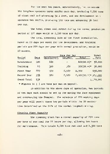
For the next two years, approximately, let us assume
the longface operates three shifts each day, producing 2,580 tons
of clean coal and advancing 32. 1 feet, and one development unit
operates two shifts, producing 320 tons and advancing 34 feet
per day.
The total clean coal output during the normal production
period of 374 days would be 2,900 tons per day.
The total operating life of the first installation,
based on 20 days per month for the development and training
periods and 220 days per year with normal production, would be
28 months.
Days
120
Tons Per Day TotalPeriod Development
480
Longwall Total Tons
Development 480(20.0)* 58,000
Training 40 320 580 900(16.+)* 36,000
First Year 220 320 2,580 2 ,900 638,000
Second Year 154 320 2,580 2 ,900(42.7)* 447,000
Grand Total 53^ 1,179,000
* Figures in ( ) are tons per man on payroll.
In addition to the above days of operation, two periods
of ten days each should be set up for moving the face equipment
and overhauling the Shearer. The schedule of 220 working days
per year will permit these two periods within the 20 months'
time determined as the life of the normal longwall mining.
Cleaning Plant Capacity
The cleaning plant has a normal capacity of 210 tons
per hour of raw coal for 22 hours per day, allowing two hours
for maintenance. This totals 4,620 tons raw coal and 4,340 tons
-48-
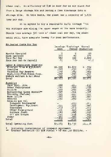
clean coal. An efficiency of 85$ is fair for an air plant fed
from a large storage bin and having a free discharge into a
storage pile. On this basis, the plant has a capacity of 3*^90
tons per day.
It is agreed to buy a reasonable daily tonnage from
the stripper now mining the upper seams on the same property.
Should this average 300 tons of clean coal per day, the plant
would still have adequate leeway for peak performances.
Estimated Costs Per TonDevelop- Training* Normal
ment Period Production
Months Operated 6 2 20Days Operated 120 40 374Tons Per Day 480 900 2,900Tons Per Man On Payroll 20 16+ 42.7
Labor & Associated ExpensesStraight Time & $30/shift $1,500 $1,870 $ .702Overtime .025 .030 .050Vacation Pay Reserve .048 .060 .022Work . Comp-FICA-Unemp . Comp
.
.197 .246 .097UMWofA Welfare & Ret. Fund .400 .400 .400Total $2,170 $2,606 $1,271
SuppliesFace Incl. Bits .280 .225 .136Other Underground .050 .050 .035Outside .040 .040 023Battery-Cap Lamps Rental** .027 .014 .005Trucking (Refuse) .025 .027 .017Mine Office .060 .055 .020General .050 .050 .017Repairs and Oil
Longwall Equipment^ - .035 .047Development Equipment .055 .020 .006Conveyors .018 .013 .013Other Underground .034
.040.023 .008
Surface Plant .040 .035Oil and Grease- .040 .038 .035
Power .180 .200 .090Total .899 .8*0 .487
Total Operating Cost $3,069 $3.^36 $1,758
* Including installation of longwall equipment** Tractor batteries (2) 90$ rental - 48 mos.,or $121/mo.
-49-
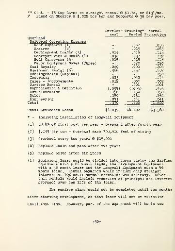
** Cont. - 75 Cap Lamps on straight rental @ $1.78, or $134/mo.# Based on Shearer @ $.025 per ton and Supports @ 3$ per year.
Develop- Training* Normalment Period Production
OverheadDeferred Operating ExpenseRoof Supports (1) - .047 • 095Shearer (2) - .085 .085Development Loader (3) .015 .015 .015Conveyor Pans & Chain (4) .032 .032 .032Belt Conveyors (5) .015 .015 .015Major Equipment Moves (Three) - .020 .020
Coal Royalty .200 .200 .200Equipment Rental (6) .366 .557 .697Contingencies (Capital) - - .050Insurance .023 .042 .014Taxes - Improvements .012 .006 .002Surface Rental - .001 .001Depreciation & Depletion (.034) (.695) .255Administration .150 .150 .150Sales .150 .150 .150Engineering .041 .041 .041Total .970 .666 1.822
Total Estimated Costs $4,039 $4,102 $3,580
* - Including installation of longwall equipment
(1) 10.8$ of first cost per year - Overhaul after fourth year
(2) $.095 per ton - Overhaul each 700,000 feet of mining
(3) Overhaul every two years @ $15,000
(4) Replace chain and pans after two years
(5) Replace belts after six years
(6) Equipment, lease would be divided into three parts- the SurfaceEquipment" with a 26 month lease, the Development Equipmentwith a 52 month lease and the Longwall Equipment with a 46month lease. Rental payments would include only straightinterest at 10$ until normal operation was underway. Afterthat rentals would include reduction of principal and interestaveraged over the life of the lease.
The surface plant would not be completed until two months
after starting development, so that lease will not be effective
until that time. However, part of the equipment will be in use
-50-

so assume for each of these two months that rental includes one-
half of the monthly Interest. From then until normal production
the rental would be straight interest.
It is most probable that after the Demonstration Mine
is finished at the Windber location the surface plant would con-
tinue to be used by local small operators who do not have sufficient
capital to invest in cleaning and storage for half-trainload ship-
ment. Without these two very necessary facilities, these operators
are now very seriously handicapped and may have been forced out of
business. However, for our purpose it is assumed that the surface
plant must be amortized during the 20 month period.
Lease Projections
Surface Equipment
Development Equipment
Longwall Equipment
It may prove advisable from a tax standpoint to increase
equipment rental payments by shortening the life of the equipment
leases. This will depend upon conditions and circumstances sur-
rounding the second location for the longwall equipment. A
provision for such an option should be embodied in the lease to
avoid later problems.
Purchased Coal Cost Discussion
The purchased strip coal should absorb its pro rata
share of costs involved with cleaning and storing and overhead,
as well as allow a small profit. Therefore, in arriving at a
EquipmentCost Period
26 Mos.
ReductionPrincipal
20 Mos.
MonthlyRentals
$ 115,775 $ 6,600
327,670 52 " 44 "9,164
763,410 46 " 44 " 21,346
$1,206,855 $37,110
-51-

fair price for this product, the following cost items should be
deducted from the realization:
Outside Supplies $.023Refuse .034Cleaning Plant .030Loading .028Mine Office .010Surface Plant Repairs .035Power .020Surface Equipment Rental .075Surface Equip. Depreciation .019Administration .075Sales .150Profit .250
$.749
Assuming the coal sales price to be $4.10, then a fair
price for the purchased strip coal on a clean coal basis would
be $4.10 - .75, or $3.35.
The purchase and sale of this strip coal would reduce
total costs as follows:
Without Strip Coal With Strip Coal
Development Period $4,039 $3-78
Training Period 4.102 3. 91
Normal Period 3.580 3.56
The strip coal should be handled as a separate operation
to avoid distortion of the results from the demonstration project.
-52-

Investment - Specifications
Initial Development Period
General
10 Core Drill HolesGrading-Drainage -RoadsLegal-Permits -BondsCompensation InsuranceCoal Lease DepositPower Line to Plant (3,800')Siding Extension Sub gradeSiding Extension Track
Total
Surface
Temporary - #1 Butt Development
650' Belt Conveyor (Used)-#1 Butt to TruckBin**Cut through Lowwall opposite #1 ButtTemporary mounting of Bradford BreakerTemporary appendage on truck bin for refuse
Total
Raw Coal Transportation*
1425' 30" Raw Coal Conveyor (Used) -Trestle2 Merrick Weightometers - Totalizer -
Test Chain50 ton T-^uck Bin - Ramp )
800 ton Silo - Roof - Feederj180 ' 30" Feed Conveyor (Used)j
to Plant - Trestle )
Total
Cleaning Plant 4
8'xl4' Bradford Breaker3 (Used) R&S 6' Air Tables Complete13c - 18" Refuse Belt Conveyor-Trestle50 ton Refuse Bin
Total
Deposit Cash
$ - $ 2,0003,000
1,000 500* _
10,000 -
- 5,0009,900 -
15,000 -
$ 35,900 $ 10,500
9,000900
1,5001,000
$ 9,000
$ 12,400 $ 9,000
$ 22,750 $ 38,500
7,735
23,800 7,400
$ 46,550 $ 53,635
107,2008,000
6,000
$107,200 $ 14,000
* Operating company would include this new mine with present policy.** Drive-Tail Piece-Cover Only. (For later use #2 Butt to #3 Butt)• Turnkey basis.
-53"
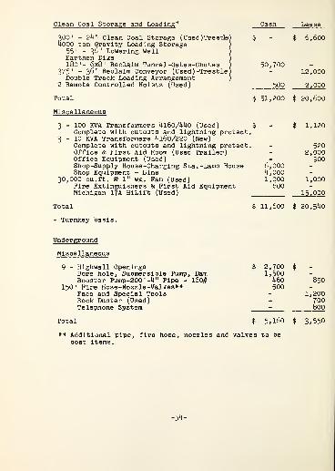
Clean Coal Storage and Loading 4
300' - 24" Clean Coal Storage (Used) Trestle)4000 ton Gravity Loading Storage
55' - 36" Lowering WellEarthen Dike180'- 6x8' Reclaim Tunnel-Gates-Chutes
375' - 36" Reclaim Conveyor (Used ) -Trestle
j
Double Track Loading Arrangement2 Remote Controlled Hoists (Used)
Total
Miscellaneous
3 - 100 KVA Transformers 4160/440 (Used)Complete with cutouts and lightning protect.
3 - 10 KVA Transformers 4160/220 (New)Complete with cutouts and lightning protect.Office & First Aid Room (Used Trailer)Office Equipment (Used)Shop-Supply House -Charging Sta.-Lamp HouseShop Equipment - Bins
30,000 cu.ft. @ 1" wg. Fan (Used)Fire Extinguishers & First Aid EquipmentMichigan 17A HiLift (Used)
Total
* Turnkey basis.
50,700
500
Lease
$ 6,600
12,000
2,000
$ 51,200 $ 20,600
$ 1,120
- 520- 2,000- 900
6,000 -
4,ooo -
1,000 1,000600 -
15,000
$ 11,600 $ 20,540
Underground
Miscellaneous
9 - Highwall OpeningsBore hole, Submersible Pump, DamBooster Pump-200'-4" Pipe - l60#
150' Fire Hose-Nozzle-Valves**Face and Special ToolsRock Duster (Used)Telephone System
$ 2,700 5
1,500 -
460 850500 -
- 1,200- 700- 800
$ 5,160
** Additional pipe,cost items.
fire hose, nozzles and valves to be
3.550
-54-

Underground Cont
.
Cash Lease
Power
Surface Substation - 4l6o V.-Non closingBreaker - Arrestors - Disconnects -
Grounding Resistor and Check System withenclosure for mine entry as required byCommonwealth of Pennsylvania - $ 7*000Fence and Miscellaneous 800
5 - 1000* lengths #2 - 3/C, SHD Cables-5000 V. - 15,58510 - Cable mounting Sockets and Receptacles - 2,500
600 KVA Air Cooled Transformer - 4160-550 V.
,
including skid mounting - incoming gearplug - cutouts - 3 transformer core andcoils - Lightning arrestors - secondarygrounding resistor - 3 secondary circuitseach 800 amp. breaker - ground trip pro-tection - 3 output receptacle and pluginterlock system - $ 12,700
3200' - 4/0 - 3/C-G Cable - 600 V. - 14,290Underground Distribution Centers - 550 V.
A. Development - 5 circuit, skid mounted,Each circuit 5-7 amp. unbalanced phaseground trip - output receptacle and plugs-Total connected loads 240 HP - „ - 2,815
B. Head Stable - 5 circuit same as A - withTotal connected loads of 160 HP - - 2,625
Total $ 800 $ 57 , 515
Transportation
Coal
2 - 2400' - 30" rope frame Belt Conveyors -
75 HP Drives Complete with Controls - $143,850
Men and Supplies
Kersey 944 - Open type TractorWinch for Tractor
4 - 1\ ton Trailers2 - Personnel Cars - Batteries and Charger
Charger for Tractor2 sets Tractor Batteries (90$ rental)
Delivery of Above
Total - $ 16,595
- $ 5,775- 1,400- 1,740- 5,405- 1,475- 650- $ 150
-55-
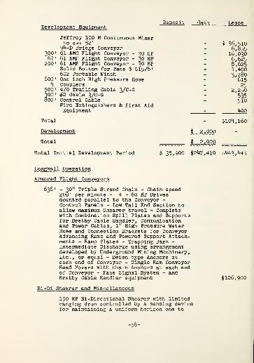
Deposit GashDevelopment Equipment
Jeffrey 100 M Continuous Minerto cut 52"94-D Bridge Conveyor
300" 61 AMC Plight Conveyor - 30 HP67 ' 61 AMF Flight Conveyor - 30 HP
200' 61 AMF Flight Conveyor - 30 HPSolid Bottom for Pans @ $15/6'602 Portable Winch
600' One inch High Pressure Hose
4 Couplers500' 4/0 Trailing Cable 3/C-G300' #2 Cable 3/C-G800' Control Cable
Fire Extinguishers & First AidEquipment
Total
Development
Total
$ 56,510- 6,855- 16,030- 6,625- 8,625- 1,400- 3*780- 615- 25- 2,250- 535- 510
_ 400
- $104,160
$ 2 j 000 -
$ 2,000
Total Initial Development Period $ 35,900 $247,410 $443,445
Longwall Operation
Armored Flight Conveyors
636' - 30" Triple Strand Chain - Chain speed200 • per minute - 4 - 60 HP Drivesmounted parallel to the Conveyor -
Control Panels - Low Tail End Section toallow maximum Shearer travel - Completewith Combination Spill Plates and Supportsfor Bretby Cable Handler, Communicationand Power Cables, 1" High Pressure WaterHose and Connection Brackets for ConveyorAdvancing Rams and Powered Support Attach-ments - Ramp Plates - Trapping Bars -
Intermediate Discharge using arrangementdeveloped by Underground Mining Machinery,Ltd., or equal - Beien type Anchors ateach end of Conveyor - Single Ram ConveyorHead Movers with Chain Anchors at each endof Conveyor - Face Signal System - andBretby Cable Handler equipment $106,900
Bi-Dl Shearer and Miscellaneous
150 HP Bi-Directional Shearer with limitedranging drum controlled by a sensing devicefor maintaining a uniform horizon one to
-56-

Bi-Di Shearer and Miscellaneous - Cont
.
Lease
two Inches off floor coal - A haulage chainchain is preferable, but if space cannot bemade available for the chain anchor withinthe stable width limitations set out InDrawings B-6-11 & 12-Equipment Detail-Headand Tail Stables, then cable can be used -
Complete with Controls - Double spiral vanedisc for cutting 44" x 27" and loading cowl,both of a make which has proven satisfactory $ 48,900
A second dr*um-4l" x 27" and cowl 3*500700" 4/0 - 3/C-G Shearer Cable 3,150700' #8 - 2/C Control Cable 450800' One inch - 400# Water Hose 820
Total $ 56,820
Powered Roof Supports
Six leg Supports to extend from rib to rib(639') with practical end clearance at ribs-Having waste edge yield of 40 tons perlineal foot of face with margin of capacityfor later installation of approximately48 tons per lineal foot by change of reliefvalves - Because of the rash problem, minimumcenters are specified even though supportstrength would permit larger centers -
Canopies to be of large area and articulated-The support advance is to be by servo-lower-ing at a cycle speed of about six seconds -
Conveyor advance to be activated by Sheareroperator by group control - Supports are tobe advanced by group control and bothconveyor advance rams and supports to advancein sequence from either end of face - Cats-eyereflectors on front legs for aligning supports-Working range to be 44" to 32" with a height of52" by extensions for supports to be located inhigher areas in stables, See Drawings B-6-11and 12-Equipment Detail-Head and Tail Stables -
A pressure indicator to be supplied for eachrelief valve circuit so that pressure atrelief valves can be determined readily - Thehydraulic working pressure not to exceed1500 p.s.i. - The hydraulic system to beadequate to operate both conveyor advance andsupport advance simultaneously and hydraulicpump to be supplemented by a second pump whichautomatically goes into operation if line pres-sure is reduced - Complete with Controls -
Hydraulic fluid to be a water-oil emulsion -
-57-

Powered Roof Support s-Cont. Cash Lease
Complete with all hoses - Exposed surfacesto be treated with rust-resisting coating-To be of design in total and detail meetingapproval of the British National Coal Board $535, 040
Stage Loader and Cross Conveyor
150' Jeffrey 20" Conveyor - double strand chainwith tripper to load onto Cross Conveyor -
Capacity 450 tons per hour - Complete withdrives and controls - Tail end sectiondesigned to fit under Armored FlightConveyor - 24,000
66' 30" - 52 HC Belt Conveyor with Crawler mountedDrive Head and rope framed structure -
Capacity 450 tons per hour - Designed forrapid dismantling, moving and reassembling-Complete with Drive and Control - 15*500
Total $ 39,500
Miscellaneous
Portable Winch for advancing Stage Loader $ 3,780High Pressure Pump 1,500Power and Control Cables for Conveyorsand Winch 2,200
Hydraulic Props with Link Bars 11,440sets of 2-100 ton Self Advancing Chocks-52" height 1,500MSA Paging System - Combined loudspeakerand telephone - 50' centers across faceat loading station, on Shearer, at transferpoint and at belt loading point - Batteriesand Cable - 4,230Fire Extinguishers and First Aid Equipment ^00
$ 25,150
Development
Longwall Equipment Installation $ 8,000Training Period 17,000
$ 25,000
-58-

Investment Summary-
Deposit Cash
Initial Development Period
General $35,900 $ 10,500
Surface
Temporary for #1 ButtRaw Coal TransportationCleaning PlantClean Coal Storage and LoadingMiscellaneous
Total Surface
$ 12,40046,550107,20051,20011,600
$ 9,0005?, 63514,00020,60020,540
$228,950 $ 117,775
$ 5,160800
$ 3,55057,515
:143,85016,595
104,160
Underground
MiscellaneousPowerTransportation
CoalMen and Supplies
Development EquipmentDevelopment - 2,000
Total Underground - $ 7,9bO $ 325,670
Total Initial Development Period $35,900 $247,410 $ 443,445
Longwall Operation
Armored Flight Conveyor $ $ 106,900Bi-Di Shearer and Miscellaneous - - 56,820Powered Roof Supports - - 535, 040Stage Loader and Cross Conveyor - - 39,500Miscellaneous - - 25,150Development and Equipment Installation - 25,000 - •
Total Longwall Operation - $ 25,000 $ 763,410
Total $35,900 $272,410 $1,206,855
Summary Total $1,515,165
Allowance for Contingency 50,000
Engineering-Development-Feasibility Study-Detail Specifications-Construction Supervision-Consultation-Studies and Reports throughout2 -year life of the Operation - Less ARA Grantfor Study, or Balance to be reimbursed at$.041 per ton until liquidated 48,000
Grand Total $1,613,165
-59-
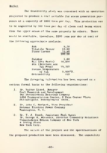
Market
The feasibility study was concerned with an operation
projected to produce a coal suitable for steam generation pur-
poses at a capacity of 2900 tons per day. This production was
to be augmented by 300 tons per day of clean coal being mined
from the upper seams of the same property by others . There
would be available, therefore, 3200 tons per day of coal of
the following approximate analysis.
Ash 8.50Volatile Matter 15.60Fixed Carbon 75.90
100.00
Sulphur 1.60Btu (Dry Basis) 14,200Btu (Moisture and
Ash Free) 15,527Fusion Temperature
of Ash 2,500°F.Grindability 103
The foregoing information has been exposed on a
serious formal basis to the following organizations:
1. Mr. Walter Lloyd, ManagerCoal Research and DevelopmentThe Pennsylvania Railroad Company1534 Transportation Center, 6 Penn Center PlazaPhiladelphia, Pennsylvania 19104.
2. Mr. John C. Herbert, Vice PresidentPotomac Electric Power CompanyWashington, D. C.
3. Mr. T. J. Trueb, Assistant Fuel AgentMr. George R. Minasian, Director Community RelationsConsolidated Edison Company of New York4 Irving PlaceNew York City.
The nature of the project and the specifications of
the proposed production have been discussed. The capability
-60-
of the property is shipment in half train loads of 3500 tons
which would be acceptable to the Pennsylvania Railroad, on
which line the shipment would originate. The two companies,
Consolidated Edison and Potomac Electric, enjoy close relation-
ship with the Pennsylvania Railroad. Both utility companies
are acquainted with coal from the C' seam. Potomac Electric
has been running tests at its Chalk Point Station on coal
from this area and of the analysis disclosed. There is no
unsurmountable obstacle to its use. It is using some of this
coal presently.
Consolidated Edison has been a user of C' coal but
has been using coal of higher volatile content of late. It
is considering lowering its specification for volatile content
and would give C' coal consideration if available in quantity
at a satisfactory price.
At the present time there is a demand for steam coal
for export and coal from the demonstration mine would meet the
specifications
.
It was considered at the outset of this project that
the Consulting Engineers should obtain commitments for the pro-
jected output of the mine. As discussions have developed and
as the project has taken shape it is the opinion of the con-
sulting engineers that firm commitment for the output would
be a usurpation of the function of the operating organization
and could work to its disadvantage should a commitment for the
production be taken at too low a price. Hard trading on behalf
of the seller would be precluded by the flexible nature of the

project during the engineering stages and before the opera-
tor's function should come into play.
Therefore the consulting engineers have undertaken
to establish a reasonable price for the product of the mine
cleaned as proposed in this feasibility study.
This reasonable price has been established as in
excess of $4.10 per share under present economic conditions.
The figure of $4.10 per ton on cars at the mine loaded as
part of a half train load shipment has been used in further
discussion
.
The consulting engineers have estimated the tonnage
of clean coal available from this property to be 1,230,000 tons
(Refer to page 15) . This would be recoverable over a period
of about 28 months (Refer to page 48 - Production Summary)
.
It is the opinion of the consulting engineers, based on inquir
directed to informed sources, that the marketing of the coal
at the rate projected can be accomplished by the operating
company.
Conclusion
The salient observations derived from the work of
this study are set out below.
The Central Pennsylvania coal reserves are adaptable
largely to longwall mining techniques using powered roof
supports and full caving. Equipment to operate under most
mining conditions and seam thicknesses of Central Pennsylvania
is now available but must be chosen and applied properly.
The C (C prime) seam has the largest reserves of
the various seams in Somerset County.
The site chosen for the Demonstration Mine in the
C seam has mining conditions adapted to the longwall system
of mining.
Inquiry into market conditions discloses assurance
that a 13,600 B.t.u. product at $4.10 per ton, f.o.b. mine,
shipped in half-trainload shipments, is competitive with
residual oil on the Eastern Seaboard. A substantial market is
available to the Central Pennsylvania Field for the product at
this price both in the U.S.A. and overseas.
The C coal at this location can be mined by longwall
mining technique, cleaned and loaded in half-trainload lots as
a 13,600 B.t.u. (as received) product and be profitable with a
realization of $4.10 per ton.
Larger operators in the Central Pennsylvania area,
though hesitant to try the new technique themselves, are
developing a keen interest, engendered by the activity and
discussions preparatory to the launching of the Demonstration
Mine project. This interest is quickened also by the sales
promotion of manufacturers who have begun to sell longwall
equipment in the U.S.A. and by the decision of Bethlehem
Steel Company to make an installation in Cambria County. The
Bethlehem Steel installation, naturally, will not be readily
available for observation until it has been perfected, and it
is questionable whether Bethlehem policy would permit overall
cost data to be made public for some time, if ever. The
Demonstration Mine would provide the location where observa-
tions could be made readily and cost figures examined by
individuals or groups with genuine interest in its performance.
Longwall mining equipment can be made available to
operators on a leasing basis. A well-known industrial banking
organization has examined the nature of the demonstration mine
installation and has expressed interest in leasing the equip-
ment to an acceptable operator on the basis of a feasibility
study such as this paper.
Since longwall mining installations require a rela-
tively high capital expenditure, leasing would place the
necessary equipment within the reach of operators who might
otherwise be deprived of the opportunity.
Longwall mining machinery and equipment can enjoy
the privilege of insurance protection by responsible carriers
The rates are dependent upon the experience and character of
the operating group, as well as mining conditions.
The property examined and projected in this study

will require a total capital expenditure to equip it for
longwall mining exclusive of working capital but inclusive
of an allowance for contingencies of $50,000, of an amount
of $1,613,165 which would be divided as follows:
Deposits $ 35,900Cash expenditures 272,410Total Cash required 308,310Leased equipment 1,206,855Allowance for contingency 50,000Engineering 48, 000
Total $1,613,165
This property is expected to generate cash from its
operation in the following manner and amounts:
Total Cash Realization*1,230,000 tons at $4.10 $5,043,000
It should generate Net ProfitBefore Taxes at presentprices of 639,600
It will develop from internalfunds (depreciation anddepletion) 313,650
Total Cash generation $ 953,250
The total cash generation isin excess of lease paymentsfor equipment and the advan-tageous acquisitions possibleas a result thereof.
Projected Balance Sheets andStatements of Source and Ap-plication of funds and Profit-ability are omitted since theoperator and terms and condi-tions of financing are yetundetermined
.
Exclusive of sales of any strip mine coal purchasedand processed by the cleaning plant
.
Recommendation
It is the opinion of the consulting engineers
that the property studied is suitable for longwall mining
with caving and will provide a profitable initial step for
the operating group to practice the longwall art. A second
property suitable for longwall practice, accessible to the
first, is an essential part of the total program to provide
continuous profitable operation. There are properties
available known to the consulting engineers which would
satisfy this condition.
The project is recommended, therefore, as being
feasible
.
/jL-U ^J^r £//L~-Allison L. Bayles & Associates
14 October 1964
-66
EXHIBIT I
By and Between
The Berwind-White Coal Mining Company
and
Somerset County Development Council
Community Development Associationof Windber


OPTION
THIS INDENTURE, made and concluded this 12th dayof June, 1964, by and between THE BERWIND-WHITE COAL MININGCOMPANY, a corporation organized and existing under the lawsof the Commonwealth of Pennsylvania, party of the first part,
AND
SOMERSET COUNTY DEVELOPMENT COUNCIL, whose placeof business is at 118 West Main Street, Somerset, Pennsylvania,and COMMUNITY DEVELOPMENT ASSOCIATION OF WINDBER, whose placeof business is at 505 Fifteenth Street, Windber, Pennsylvania,
-
both non-profit corporations organized and existing under thelaws of the Commonwealth of Pennsylvania,
R
THEIR NOMINEE, subject to the approval of BERWIND-WHITE, parties of the second part.
WITNESSETH:
WHEREAS, the party of the first part is owner ofcertain coal lands situate in the Township of Paint and theBorough of Windber, County of Somerset, and Commonwealth ofPennsylvania, hereinafter referred to and more particularlyset forth in a Lease Agreement hereto attached and markedExhibit "A"; and
WHEREAS, the parties of the second part have spon-sored an economic and engineering study to determine thefeasibility of establishing in Central Pennsylvania a demon-stration mine using a so-called longwall system of mining withpowered roof supports to demonstrate that this technique canbe applied successfully to produce coal from thin seams of thearea at a price to be delivered to the Eastern Seaboard incompetition with residual oil. If said study proves the aboveto the satisfaction of all concerned, then the parties of thesecond part will enter into a Lease Agreement with the partyof the first part under terms as outlined in the aforesaidExhibit "A"
.
NOW, THEREFORE, in consideration of the payment ofOne Dollar ($1.00) by the parties of the second part to theparty of the first part, the receipt of which is hereby acknow-ledged, the said party of the first part does hereby grant tothe parties of the second part, the right to go upon saidpremises at any time during the term of this Option, through
EXHIBIT I -1-
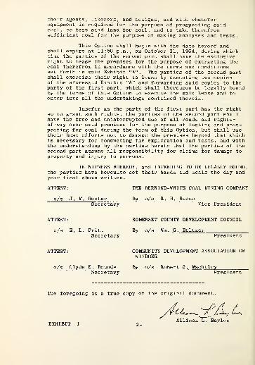
their agents, laborers, and assigns, and with whateverequipment is required for the purpose of prospecting saidcoal, to test said land for coal, and to take therefromsufficient coal for the purpose of making analyses and tests.
This Option shall begin with the date hereof andshall expire at 11:50 p.m., on October 31, 1964, during whichtime the parties of the second part shall have the exclusiveright to lease the premises for the purpose of extracting thecoal therefrom in accordance with the terms and conditionsset forth in said Exhibit "A". The parties of the second partshall exercise their right to lease by executing two copiesof the aforesaid Exhibit "A" and forwarding said copies to theparty of the first part, which shall thereupon be legally boundby the terms of this Option to execute the said Lease and toenter into all the undertakings contained therein.
Insofar as the party of the first part has the rightso to grant such rights, the parties of the second part shallhave the free and uninterrupted use of all roads and rights-of-way over said premises for the purpose of testing and pros-pecting for coal during the term of this Option, but shall usetheir best efforts not to damage the premises beyond that whichis necessary for conducting the exploration and tests, and withthe understanding by the parties hereto that the parties of thesecond part assume all responsibility for claims for damage toproperty and injury to persons.
IN WITNESS WHEREOF, and INTENDING TO BE LEGALLY BOUND,the parties have hereunto set their hands and seals the day andyear first above written.
ATTEST: THE BERWIND-WHITE COAL MINING COMPANY
o/s J. M. BaxterSecretary
By o/sVice President
ATTEST:
o/s E. L. PrittSecretary
SOMERSET COUNTY DEVELOPMENT COUNCIL
By o/s Wm. G. Baltzer
o/s Clyde E. BoundsSecretary
COMMUNITY DEVELOPMENT ASSOCIATION OFWINDBER
By o/s Robert G. Machtley
The foregoing is a true copy of the original document.
EXHIBIT I _ 2 -
£~*>
Allison L. Bayles

EXHIBIT II
Report of Analysis of Coal
and
Washability Studies
by
Warner Laboratories, Inc.
Cresson, Pennsylvania
January 10, 1964
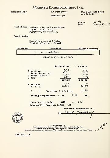
Warner Laboratories, Inc.
Established 1923 617 First Street
CRESSON, PA.
Phone Cresson 88-6-7400
Area Code 814
Received from Allison L. Bayles & Associates,
713 St. James Street,Pittsburgh, Pennsylvania,
Sample Marked
Composite Sample of C Coal,
Float @ 1.60 ^ raw - 20 mesh.
271793January 10, 196)
R»c»lvd at Laboratory
M, Albert Evans
REPORT OF ANALYSIS OF COAL.
% Moisture% Volatile Matter% Fixed Carbon% Ash
% Sulphur
As Received
0.9815.5775.637.82
100.00
1.20ll»,l60
Dry Basis
xxxxx15.7276.387.90
1.21
la, 300
B. t. u. (Moisture & Ash Free)
Fusing Temperature of Ash 2780
15,527
Coke Button Index ASTM
OrLndabillty (Hardgrove Index)
3 1/2
WARNER LABORATORIES, INl
Maui*
BORATOH
JCyr/£'&&>^
WE SPECIALIZE IN:
Campl.lt Analyses oi Coal and Coke. Grindabillty and Washablllty Tests.
Ultimata Analyses ol Ash. Analyses ol Clay-Lime-Limestone.
Chemical and Bacteriological Analyses ol Water Supplies and Analyses ol Mine and Boiler Water.
EXHIBIT II

Warner Laboratories, Inc.
Allison L. Bayles St Associates713 St. James StreetPittsburgh, Pennsylvania
CRESSON. PENNA.
January 10, I96I4
December, 1963received: January. 196h
REPORT Sampled by M. Albert F.vans
Sample 1A - 3AIB - 3B
• U - $k - 6A• I4B - SB - 6B
Plus 20 Mesh Float @ 1.60Sink @ 1.60
Calculated Analysis Raw Coal
Samples 1C - 3C - bC - 5C - 6C
Plus 20 Mesh Float @ 1.60Sink @ 1.60
Calculated Analysis Raw Coal
Weight % Ash Sulphur
73.20 %26.80
9.50 %50.8820.59
2.29 %7.183.60
9b.n %5.53
7.71 %hi. 57
9.92
1.01 %
21.612.15
EXHIBIT II
WARNER LABORATORIES. INC.
ItikJW ItLrfeJ*^
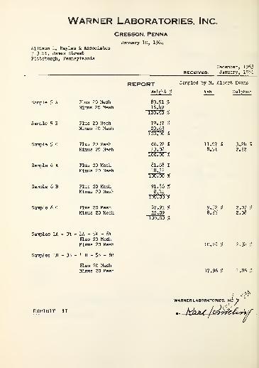
Warner Laboratories, Inc.
CRESSON. PENNA.
Allison L. Bayles & Associates713 St. James StreetPittsburgh, Pennsylvania
January 10, 1?6L
December, 1963RECEIVED: January, 196Li
REPORT Sampled by M. Albert Evans
Weight % Ash Sulphur
Sample 5 A Plus 20 MeshMinus 20 Mesh
83.51 %16.19
100. 00 %
Sample 5 B Plus 20 MeshMinus 20 Mesh
79.37 %20.63
100. 00 %
Sample 5 C Plus 20 MeshMinus 20 Mesh
86.92 %13.08
100.00 %
11.07 %8.51
3.2L %2.22
Sample 6 A Plus 20 MeshMinus 20 Mesh
81.68 %18.32
100.00 %
Sample 6 B Plus 20 MeshMinus 20 Mesh
91.86 %8.1L
100.00 %
Sample 6 C Plus 20 MeshMinus 20 Mesh
87.91 %12.09
100.00 %
9.52 %8.55
2.07 %2.08
Samples 1A - 3A - U - 5A - 6A
Plus 20 MeshMinus 20 Mesh 10.28 % 2.3L %
Samples IB - 3B - h B - 5B - 6B
Plus 20 MeshMinus 20 Mesh 17.96 % 1.86 %
EXHIBIT II
WARNER LABORATORIES. Ii, INC.Y
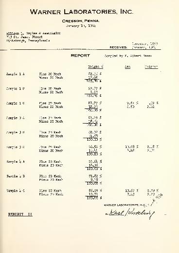
Warner Laboratories, Inc.
CRESSON. PENNA.January 10, 1961
Allison L. Bayles & Associates
713 St. James StreetPittsburgh, Pennsylvania
December, 1963RECEIVED: January, I96J4
REPORT Sampled by M. Albert Evans
Weight % Sulphur
Sample 1 A Plus 20 MeshMinus 20 Mesh
82.35 %17.65
166.06 %
Sample 1 B Plus 20 MeshMinus 20 Mesh
92.77 %7.23
100.00 %
Sample 1 C Plus 20 MeshMinus 20 Mesh
87.77 %12.23
160.66 %
9.61 %8.50
1.59 %
2. ho
Sample 3 A Plus 20 MeshMinus 20 Mesh
81.26 %I8.7li
166.60 %
Sample 3 B Plus 20 MeshMinus 20 Mesh
88.32 %11.68100.00 %
Sample 3 C Plus 20 MeshMinus 20 Mesh
86.56 %13.I4I4
100.00 %
10.08 %8.1*6
2.U8 %2,50
Sample I4 A Plus 20 MeshMinus 20 Mesh
83.61 %16.36166.66 %
Sample Li B Plus 20 MeshMinus 20 Mesh
91.82 %8.18
100c 00 %
Sample Li C Plus 20 MeshMinus 20 Mesh
86.29 %13.71
100.00 %
10.67 %
7.h3
WARNER LABORATORIES.
2.79 %
EXHIBIT II «,Mh£ /*4r&<A*\/>

ALLISON L. BAYLES 8 ASSOCIATES
CONSULTING ENGINEERS
1 April 1965
Mr. Frank A. CirilloChief Technical Projects ManagerArea Redevelopment AdministrationU. S. Department of CommerceWashington, D. C. 20230
Reference: PR-30 - Project No. 6'
Contract Cc-6114Dear Mr. Cirillo:
It is a pleasure to transmit with this letter aReport entitled, "Supplement to Feasibility Study, Demon-stration Mine Using Longwall Mining Techniques, Windber,Somerset County, Pennsylvania".
This Supplement, together with the PreliminaryReport offered on 14 October 1964, will constitute a com-pleted report described under Article I, Section D, Sub-section 3 .
We are of the impression that the FeasibilityStudy of the Demonstration Mine Using Longwall Mining Tech-niques has been submitted to interested parties and hasreceived tentative approval without serious comment to alterthe schedule.
The Feasibility Study plus the Supplement willpresent to ARA the method of bringing this project tofruition, the Supplement and the Feasibility Study to betreo.ted as one and stand on their content.
Upon receipt of approval by you, with such commentsas are pertinent to the substance of the report, the Con-sulting Engineers (the Contractor) will furnish the govern-ment with the necessary copies of the final report as pre-scribed in the Contract dated 20 December 1963 and subsequentamendments, and as agreed upon with Mr. I. M. Baill.
Faithfully yours,
r Allison L. Bayles & Associates
Supplement
24 March 1965
Feasibility Study
DEMONSTRATION MINE
Using
LONGWALL MINING TECHNIQUES
Windber
Somerset County
Pennsylvania
U.S. DEPARTMENT OF COMMERCEJohn T. Connor, Secretary
Eugene P. Foley, Assistant Secretaryand Director of Economic Development

INDEX
Letter of Transmittal
Title Page
Introduction
The Transition
Capital Requirements and the Financial Structure
The Projections of the Results to be expectedfrom the Operation of the Property
EXHIBITS
Exhibit A - Map: Optioned Areas 1, 2 & 3Drawing B-10-15
Exhibit B - Investment SummaryI - Initial InvestmentII - Additional Capital InvestmentIII - Equipment Leasing TermsIV - Capital Requirement & Sources
of Funds for Operating Company
Exhibit C - Expense ProjectionsReconciliation with Feasibility Study
I - Operating ExpenseII - Overhead Expense
Exhibit D - Timetable of Projected Operationsand Production
Exhibit E - Projected Comparative Statement ofIncome and Retained Earnings
Exhibit F - Projected Source & Application ofFunds Statement
Exhibit G - Projected Comparative Balance Sheets
SUPPLEMENT
24 March 1965
This Supplement and the Feasibility Study of the
Demonstration Mine Using Longwall Mining Techniques, submitted
to the Area Redevelopment Administration on 14 October 1964,
constitute the final report to be supplied to ARA . The pur-
pose of the Supplement is to supply the following information:
1. The transition steps from the FeasibilityStudy necessary to achieve an operatingmining property.
2. Capital requirements and the financialstructure necessary to support the venture.
3. The projection of the results to be expectedfrom the operation of the property.
1 . The Transition
The Introduction to the Feasibility Study set out
the task of the Consulting Engineers which would include, but
not limit to, the following accomplishments:
"Preliminary Investigation - Study the strata andseam characteristics in adjoining mines and consultwith experienced operators of the same seam in thearea to back up preliminary findings which werelimited to the study of core drill data and highwallobservations. - Take channel samples along the high-wall and have a washability study made to determinethe amount and type of cleaning necessary to meetthe proposed market requirements.
Select the seam and area for the second installationand study the strata and seam characteristics inorder that the face equipment can be designed forboth mining conditions.
1. Obtain options on the surface and coal.
2. Carry through the market survey to assure outletsfor the product of this operation and secure commit-ments for the output
.
3. Make surface surveys, surface and mine layouts,detailed plans and specification for mine, prepara-tion plant, storage and rapid loading facilities,select equipment, prepare a definitive estimate ofcapital expenditures and prepare a projection ofoperating costs.
4. Select a coal company to operate the projectthrough the first and second installations.
5. Prepare progress reports, a preliminary draft,a report on the trip (to the United Kingdom) and afinal report.
6. Inspection of facilities in the United Kingdom.
The work was authorized on 20 December 1963."
As the work has progressed there have been changes
in concept which will be described in the subsequent paragraphs.
The preliminary investigation cited above has been
completed. The scene for the second installation has been
selected. The options on the surface and coal, set out as
Item 1 above and on Page ii of the Feasibility Study, have been
obtained
.
The market survey described in Item 2 above has been
completed, but the commitments for the output of coal have not
been secured. This matter is treated on Page 60 of the Feasi-
bility Study. In brief, it was felt by the Consulting Engineers
that though the coal would be marketable at the price selected
for the study, it would be improper to secure commitments for
the output, since it could be a usurpation of the prerogative
of the coal mining company to be selected to operate the property.
The surface surveys, surface and mine layouts,
detailed plans and specification for mine, preparation plant,
storage and rapid loading facilities and selection of equip-
ment, together with a definitive estimate of capital expendi-
tures and a projection of operating costs described under
Item 3 above, have been completed.
The coal company to operate the project through
the first and second installations set out in Item 4 above
has not been selected. Those considered have been unavailable
or ineligible for reasons which need not be part of this
report
.
The trip to the United Kingdom contemplated under
Item 5 above has become unnecessary for reasons which will
become apparent
.
Scrutiny of the Feasibility Study will disclose that
it was planned originally to operate the selected property at
Windber, described therein, until its coal became exhausted.
At that time it was proposed to move the equipment to an ap-
propriate property owned by the mining company operating the
Demonstration Mine. Since the operators considered were either
unavailable or ineligible, a different procedure has been
adopted
.
A company will be formed to operate the mine. This
company will be composed of the representatives of the financ-
ing agencies, the Consulting Engineers and possibly the Coal
Sales Agents and certain representatives of suppliers of
equipment
.

A contract will be made with the Consulting Engineers
to select and oversee the operating management of the company,
for a fee. In addition, the Consulting Engineers will issue
statements as originally contemplated to disclose the mining
costs of the venture to persons with bona fide interest.
The second location has been selected and consists
of two parcels of property which are contiguous to that property
described in the Feasibility Study. The topographic relation-
ship of the three properties is set out in Drawing B-10-15,
appended as Exhibit A - Optioned Areas 1, 2 and 3 - Proposed
Demonstration Mine, East of Windber, Pennsylvania. The three
properties have estimated available coal as indicated below.
Corresponding recoverable coal is shown as Projected Coal
Production
.
Estimated Available Coal Projected Coal Production
Property #1 1,230,000 1,165,000
Property #2 1,270,000 1,236,400
Property #3 2,900,000 2,881,000
Total 5,400,000 Tons 5,283,000 Tons
This amount of coal is expected to be adequate to
carry the project through the complete depreciation of the
equipment
.
It is possible that the options on the two additional
pieces of property designated as No . 2 and No. 3 may not be
exercised since certain other properties of larger magnitude
may become available on an advantageous basis. However, it is
reaffirmed that the properties presently optioned will carry
the mine to the complete depreciation of the equipment, and the

figures displayed later herein are based on this premise.
The foregoing delineation sets out the changes
which have been made in the project described in the
Feasibility Study and enable consideration of the projec-
tions which follow.
2 . Capital Requirements and the Financial Structure
There have been some changes in the capital in-
vestment required to make the property operative. These
changes are set out and reconciled in Exhibit B - Investment
Summary. It will be seen that the initial capital invest-
ment required is made up as follows:
Deposits 40,900Cash 408,610Leased Equipment 1,206,855
Total 1,656,365
The sources of funds to supply cash for initial
capital expenditures are set out for this study as displayed
below:
Leased Equipment $1,206,855Seven Year 8% Debentures 500,000Capital Stock 125,000
Total $1,831,855
The excess of $1,831,855 over $1,656,365 will be
available for working capital
.
Additional capital expenditures will be necessary
in 1967 to the extent of $436,800 to utilize the second prop-
erty and in 1968 in amount of $85,500 to utilize the third
property. These amounts will be supplied from cash generated

by the operation of this mine.
3 . The Projections of the Results to be expectedfrom the operation of the property
There have been some changes in operating costs
set out on Pages 49 and 50 of the Feasibility Study which are
described and reconciled in Exhibit C - Expense Projections.
The sequence of steps and the time of occurrence
to achieve the projected results are set out in Exhibit D -
Time Table of Projected Operations and Production - Demonstra-
tion Mine. The exhibit and its footnotes are believed to be
understandable without further discussion.
The reconciliation displayed and discussed in
Exhibit C has been incorporated into the Projected Comparative
Statement of Income and Retained Earnings, displayed as
Exhibit E of this Supplement.
The Projected Source and Application of Funds
Statement for the period treated in the projections is appended
as Exhibit F.
The Comparative Balance Sheets for the period are
displayed as Exhibit G.
These statements are appropriately footnoted so that
they stand on their own content. They are intended to reflect
the course of the projected operation of the mine from July 1965
through 1973, a period of eight and one-half years. This period
will be adequate to permit writeoff of equipment by deprecia-
tion, the amortization of other expenses, and the liquidation
of long term and other indebtedness, and yet provide for a
return of 175% of the originally invested equity.
-6-

To The Supplement
Exhibit A - Map: Optioned Areas 1, 2 & 3.Drawing B-10-15
Exhibit B - Investment Summary
Exhibit C - Expense ProjectionsReconciliation with Feasibility Study
Exhibit D - Timetable of Projected Operationsand Production
Exhibit E - Projected Comparative StatementOf Income and Retained Earnings
Exhibit F - Projected Source and ApplicationOf Funds Statement
Exhibit G - Projected Comparative Balance Sheets


Page 1
Investment Summary
This Supplement contemplates a total investment inthe Demonstration Mine of $2,178,665, exclusive of workingcapital. As indicated by statements made in the text (page 5)of this Supplement, the total investment consists of threeparts - the initial investment, and two additional investmentsto be made later for the utilization of Property Areas 2 & 3,thus :
1. Initial Investment $1,656,3652. Additional Investment - Area 2 436,8003. Additional Investment - Area 3 85, 500
$2,178,665
Initial Investment
The initial investment projected in this Supplementcontains expenditures amounting to $43,200 not contemplatedin the original study. The Investment Summary contained inpage 59 of the Feasibility Study has been revised to includethese additions. The revised form is exhibited herein as:Initial Investment - Revised Summary. It has been condensedto display only totals for categories in which no revisionis made, namely: Surface; Underground; and Longwall Operations.Where additions have been made the affected items are markedby an asterisk (*). A detailed accounting of the additionsfollows the Summary under the caption - Additions IncludedIn Revised Investment Summary. The latter in turn is followedby analyses of deposits and cash investment identified as:Analysis of Recoverable Deposits; and Analysis of InitialCash Investment.
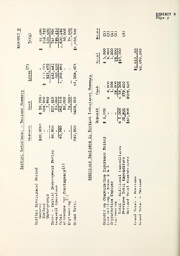
Page 2
o m oO CM COCD t*. CD
m o<J> rH
mooCO o oCO o o
mCDCO
rH CO COCO rf CO
CO CO
rH 00Tf 00
O O COco m t^m
COmCD
r-i Ho o o oo o o oOONO
m of- CD
m oinoo i
i> mrH CMrH CO
CO COTj< CO
CDoCM
rH
o o oo m cdt> G> O)
O~00 t*"CM <N
CM
o orH OCO Oi> mm cmCM
o o orH O OCO o oCM O COoo m t^CM
OCD
oo"
O
o o oo o o
I O CM O
i u a oi bC M; U rH
I rH Q) h
S3 •H CD
ed 13 h 0)
H A3 h3 <D -P 3CD CO a-H +>
a X5 T3 -Ht-H og
a> aa cm rH ft Q)
rt X! ft•H CD a W K4-> flS CD o w(J u 01 •H rHCD Jh S3 P OS rHa < a» •H P C3
a> a T3 Pa i x T3 Hs w < EhO bfi CD
o a a 1 3 T>•H o bfi o a>
a rH -H r-i rH -H CDOH+J rt > -H•h rt Sh P >
-P ij N•H Q -H
O Jh CD
H ft «
> O O rH a) o jh (
Q O O P

Page 3
Notes
(1) If actually invested the Contingency Allowance wouldgenerate a corresponding element of expense to be metin the conduct of operations. Conservative treatmentof expense projections requires inclusion of such anelement. Hence the Contingency Allowance is treatedas one of the expenditures making up the initial in-vestment. In the original Investment Summary neitherthe Contingency Allowance nor Engineering were classi-fied under any of the three types of investment -
Deposit, Cash or Lease. Both are now classified ascash investment in assets subject to either depreciationor depletion with attendant generation of expense whichis incorporated in the operating projections of thisSupplement.
(2) By original expectation the Demonstration Mine wouldhave been operated by a company having other miningoperations with a compensation insurance policy alreadyin effect. This would allow inclusion of the proposedoperation without further deposit. The new companyproposed under the present plan will be required topost a deposit. Refer Feasibility Study, page 53.
(3) The original study contemplated operations and coredrilling Area 1 only. With the inclusion of Areas 2 &3 additional core drilling is necessary.
(4) Organization Expense represents the estimated cost ofestablishing a new corporate entity to operate theDemonstration Mine. Such expenditure was not requiredunder the original plan for operation by an existingcompany.
(5) The $28,000 addition to Engineering is predicated onthe greater magnitude of the project as now contemplated.
(6) The $370,410 previous total cash expenditure is notpresent as a separate figure in the original InvestmentSummary, page 59 of the Study. It will appear uponaddition of Allowance for Contingency and Engineeringto those items which are listed as cash investment, thus:
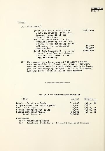
EXHIBIT BPage 4
(6) (Continued)
Total Cash Investment as set $272,410forth in original InvestmentSummary, page 59 of theFeasibility Study
Add Cash Items shown in theoriginal Summary but not in-cluded in the foregoing total
:
Allowance for ContingencyEngineering
Total Cash Investment includingitems listed but not classi-fied as Cash items in theoriginal Summary.
No changes have been made in the lease amountscontemplated by the Feasibility Study. However,modifications have been made which relate to leaseperiods and carrying charges. Refer to EquipmentLeasing Terms, Section III of this exhibit.
50,00048,000
$370,410
(7)
Item
Analysis of Recoverable Deposits
Amount Reference
Legal - Permits - BondsCompensation Insurance DepositCoal Lease DepositSiding Extension Sub-gradeSiding Extension Track
Total Deposits
References
:
(a) - Feasibility Study(c) - Additions Included in Revised Investment Summary
$ 1,000 (a) P. 535,000 (c)
10,000 (a) P. 539,900 (a) P. 5315,000 (a) P. 53
$40,900
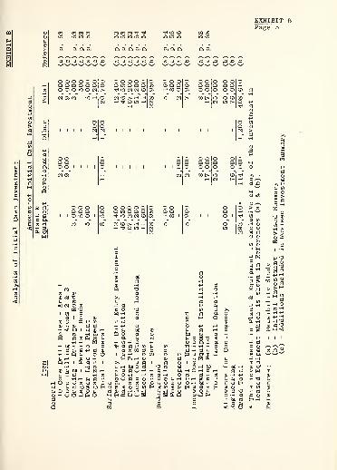
co co co com m m m CO CO CO ^ ^
in in m m inTf m com m m
oo oom m
a a a a a a a a a a a, a, a a
rt CJ c3 rt rt O £i ai cj rt a a ,a aj crj crj Xi a a & -O £2 ,Q
o o o o o oo o o o o oo o o m o cm
oo
o o o o oloo m o o o m•tf m CM CM CD 01
O O Oto o orH 00 O
oCOOS
o oo oo o
ooo
O OO OO O
oCD
CM Ol CO K5H ocm
CM CD t^ rH i-HOOrH Tf O in rH CM
rH |CM
m cm t^ 00 t*-
cmO CDm t^
00O<*
200
1ooCM
Page 5
o oo oo o
o o oo o o
i o m oo o o o oo m o o oTf m CM CM CD
o o oCD O CDH 00 I OS
o > rt3 »-"
"0
«tf L0 T3 CD
3 co 0) [fl
CO rH01CM * a > CD
cd m cc
cdm a•H HH
+-> « HI33
g -Ha•H 33 =5
"0
3p
G-rH
S 3+-> H
CD CIC
5 CM I
-a *£
! MS blh O
+> rt 3 CD a .h «" ^2+->+-> CD +-> bfi -3 3]33 rH bD CD rH a 3 3 3= rH rH <CQ rt b£ CI) rt
Oh Sh a Sh 3 g T3 is +J I 1 1
rH CO +-> O <H o a o bD 3 +-> 3% fl Of (0 rH L0 73 -H -H -H 3 3crj d W 3 3 3 3 +-> 3 U o CD S <& ^3
1 rH rH O CO |Z> rt O* r-l g aH Ph rH CD 3 U H ft u •P
>> cs d 1 3 CD 1 L0 3U <-{ bJD rt -o 03 s ftH bC bD CD crrt cd 3 O rH a a rH O rH 3 3 a w to
?H -H rH rt 3 o d crj -h a CD H +-> 3 CD
V 3 3 0) +J O CD rH +J rH > 3 +-> <J rH T3a a a o Sh CD CD OH hCH 3 CD H CD 3g £ CO H bD LO =5 > H d 3 rt H rt CD (0 (0 CD
SlHH-ri rH o& S O Eh
bB.J H=s 3 O a rHHKUOS CD s a o 3
313 3 bfi rt Ha
33 rH
p < W O * tf

o o o oo o o oo o o o
o oo oo o
Page 6
o oo oo m
a t> qo a•h g p
o o oo o o
I O O O I
H rH WP -H3 =S <H
o a a)
<H CD rH
T> -P rt
CD (fl pfc <D CD
•H > S3 a -hCfrH PCD
*H CD• J3
(fl <D PP rHa a .aCD "3 P£ CD -H4-> JC ^w ocd ca >>> +->
a bo-H•nas
•H fn
rH & O
ana
o o o o oo o o o oo o o iO o
o oo oo m
oooooooocooooooooca m oo o m Tf m m q
OHNH H-J c
-p
r* a0)
sa u,a •H
ao< rtw
o o o oo o o o
i o o m o
£! Xi £> ,Qri,Q.rt,Ori,jQaS
o oo oo m
Ooo
OOOOOOOOOOOOOOOO(CinMom^inmooco
oo
ooCX>
oo00
r-\ 0000 r4
oCMt-4
O rH <N -H Hrf mo
t>co CO
CO
mo
<D -h aXi -HHCO
°3 a
<; <
h o ^ an a -p a -p >-
3 « o a -h -h ns watq fxaaptsa-p cd 5
- -Hwaatu^ o3S3 bD CD CQ Q) 3 ft rH aa o i > o o a «s a o
H'ri fl^l ^ [flOOJrHSfltH OftflMd) dOSd)HrtH30-H^art >D^a^artoj-Hfi cd
) d8 -P
> a>3 6J D 3 J)1 r-{ & U3 ,Q 3 ^3 eJ -W .lOOIDrl
rH CD (fl +
W fi Q P
] CD .a ,* C
s ^ bCO !
) O -H O -r
n cq in ds p
fn -P !
D UPX! <D
tn p t
H O (
bflk -i
p m (1) CD
c a !-l
0) o < <s •HO.P ?H H
rt O3 ?H
cr <d
w O.P "3
O CI)
rtf a> Kl
cq P. O+-1 0,
ed o(l) 3 wM rr
0h< W <

EXHIBIT BPage 7
$ 6. 3808.,142
19.,085
Equipment Leasing Terms
Lease periods and carrying charges (interest) asoriginally contemplated have been somewhat modified. Theschedule of Lease Projections appearing in page 51 of theFeasibility Study has been revised to incorporate the modi-fications. The revised schedule follows:
Period ofEquipment Lease Principal Monthly
Lease Projections Cost Period Reduction Rentals*
Surface Equipment $ 117,775 28 Mos
.
20 Mos
.
Development Equipment 325,670 56 Mos. 48 Mos.Longwall Equipment 763,410 50 Mos. 48 Mos.
$1,206,855 $33,607
It will be understood that the revisions also applyto Footnote (6) of the Schedule of Overhead Expense containedin page 50 of the Feasibility Study.
The modifications are made in order to satisfydelivery requirements for Surface Equipment according to theoperating timetable set out in Exhibit D, and to conform torecent practice of equipment lessors. In more detail, themodifications are
:
(1) Extension by two months at the beginning of thelease period of the Surface Equipment lease. Theperiod of principal reduction and time of leasetermination remain unchanged.
(2) Extension by four months of the period of principalreduction for Development Equipment and LongwallEquipment. Times of beginning of the leaseperiods are unchanged.
(3) Carrying charges are now computed on the basis ofan annual interest rate of 5% of the initialamount of lease (Equipment Cost) without diminutionthroughout the life of the lease, rather than onthe former basis of a 10% annual interest rate ineach year on the unpaid balance of the lease amountexisting at the beginning of the year.
* Total monthly payment on account of each lease,during the period of principal reduction, in-cluding carrying charges (interest).

Page 8
These modifications are cited as an accounting fordeviations of the present projections from the FeasibilityStudy. They are of no significant effect on the project asa whole. The greatest effect is due to the levelling outof carrying charges during lease periods. Thereby suchcharges are somewhat reduced in the earlier part and increasedin the later part of a lease period. This lessens, to someextent, the working capital required during the intervalbefore operations become profitable. Total carrying chargesare slightly less than they would have been on the originalbasis.
IV - Capital Requirement and Sources ofFunds for Operating Company
Operation of the Demonstration Mine will be carriedon by a new company formed for the purpose. It is consideredthat the company will have need for capital funds as follows:
Capital Requirement of Operating Company *
Initial Investment - Revised Summary - Page 2 of this Exhibit:
Deposits (Cash)Cash Investment
Total Initial Investment
Initial Working Capital
Total Capital Requirement
The funds would be supplied by the following sources in theamounts stated.
Sources of Funds
Capital Stock $125,000Seven Year 8% Debenture Notes 500,000Total Funds Supplied $625,000
This capital structure is shown and noted in theprojected Balance Sheets of Exhibit G. Interest on theDebenture Notes is shown among Overhead Expense in the IncomeStatements of Exhibit E.
It will be understood that the investment of $1,206,855 inleased equipment will be made by the lessor of the equipment,not by the operating company.
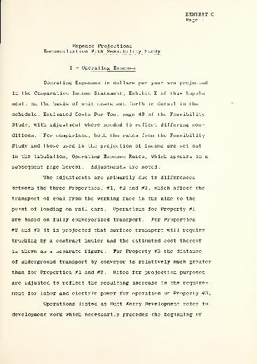
Page 1
Expense ProjectionsReconciliation With Feasibility Study
I - Operating Expense
Operating Expenses in dollars per year are projected
in the Comparative Income Statement, Exhibit E of this Supple-
ment, on the basis of unit costs set forth in detail in the
schedule, Estimated Costs Per Ton, page 49 of the Feasibility
Study, with adjustment where needed to reflect differing con-
ditions. For comparison, both the rates from the Feasibility
Study and those used in the projection of income are set out
in the tabulation, Operating Expense Rates, which appears on a
subsequent page hereof. Adjustments are noted.
The adjustments are primarily due to differences
between the three Properties, #1, #2 and #3, which affect the
transport of coal from the working face in the mine to the
point of loading on rail cars. Operations for Property #1
are based on fully conveyorized transport. For Properties
#2 and #3 it is projected that surface transport will require
trucking by a contract hauler and the estimated cost thereof
is shown as a separate figure. For Property #3 the distance
of underground transport by conveyor is relatively much greater
than for Properties #1 and #2. Rates for projection purposes
are adjusted to reflect the resulting increase in the require-
ment for labor and electric power for operation on Property #3.
Operations listed as Butt Entry Development refer to
development work which necessarily precedes the beginning of
Page 2
longwall operation in each property. Operations listed as
Longwall Operation include, in addition to actual working
of the longwall face, the butt entry work which accompanies
and proceeds simultaneously with the longwall working.
Room and Pillar Operation listed on Property #2 refers to the
use of development equipment to remove coal from a relatively
small area not suited to longwall operation.
For those years in which it is projected that only
one of the listed operations will be carried on, the listed
rates can be derived from the Projected Income Statement by
dividing annual production tonnage into the operating expense
figure. For any year in which more than, one of the listed
operations are projected such computation will yield the
weighted average rate for the particular combination of opera-
tions involved rather than the listed rates for the individual
operations
.

EXHIBIT CPage 3
co m mo oo t>
O 00rH OCO o
CO CO ^ rH 00rH rH O
CO CN r-\ CO (N <N CM CN CN CN
1 1 1
o om inCN CN
Om(N
omCM
o o oo o oCO CO CO
cd co oocd o o o oCD O 00 O CO00 00 "tf HTf m m m m
O CD rH O CD rH O rH 00 oo rH rH rHI> O l> MON CD l> CD CO O CD 00rH CD CN rH O CN CD CM CO CO CO CN CN
CD-*
0)
bfi
ri
a
>i-a^
O W>>
r-^ pJ2ri
HX2
g Hto
rt
xs ofe
a+->
03
Qu
CO
c T3oH PP rt
rt £fi
0) pa en
o w
P rt rH
G fn
H 55
-P bO bOp a g3 O O
o g•Hp s
Q ft£ Oo uu cm
CD G H CD CD P ft O CNCD -H <D a rH u o o >•rH G U rH -HI rH
i -h a> 1 t> X2 C ft CD rH CO-p rt p P CD £ O O > CD l> t>G >H <HH <
G CD -H !h J)rH O P ft Q
£ 1 w £ I rt 1 1 1
ft g c a c c ^ g ^ g g go o o O CO U OrH -H -H rH -H -rH ft ft -H -P
-P P P P O PC> rt rt > d d X3 rt H01 n n s-, u u a u nnhQ Q ei ci P
ft ft ft ftrH ft+->>>0 O rH CN O 3
ft ft ft>>o O o o oU ^ -h ft to
r-{ -P rH rH CN P rH rH ft rH CO rH rH rH
ft G rH rH ft CHH lflrH.GCDftrHrHrHH rt rt WrtrtT30rtP>co
p +-> be be>> £ £ G -H =s -H CDPP bo bfi rt P &fi £ rH
>> £ p= =s
P bfi bfi bfi
U -P C G ^ P c c Sh c U G G G3 3 O O O O
ftOQ J J ftpa ^ hJ ftiJ ftj J J

EXHIBIT CPage 4
(1)
Operating Expense Rates
Unit Costs are based on a production of 900 Tonsper Day.
(2) Unit Costs adjusted to the production of 1,200 Tonsper Day as shown in Exhibit D of this Supplement
.
(3) Compare total cost exclusive of Trucking ($3,060)with total cost of $3,069 above for Property #1 andin Feasibility Study.
(4) Computation will show that combined costs are sub-stantially equivalent to the costs of the sameoperations taken separately.
(5) Underground transport over greater distance inProperty #3 increases the requirement for labor andelectric power over the requirements of Properties #1and #2. The additional requirement diminishes withdecreasing transport distance as the working faceretreats. The increase in cost due to this factor isestimated as follows:
1969-1970
1971-1972
1973
In Labor Cost-
$0.030/Ton
0.020/Ton
0.010/Ton
IncreaseIn Supply Cost
$0.060/Ton
0.040/Ton
0.020/Ton
In Total Cost
$0.900/Ton
0.600/Ton
0.300/Ton

EXHIBIT CPage 5
II - Overhead Expense
Overhead Expenses in dollars per year are projected
in the Comparative Income Statement, Exhibit E of this Supple-
ment, in the manner described in this section.
The schedule, Estimated Costs per Ton, Overhead,
which appears in page 50 of the Feasibility Study, is a complete
and proper statement in terms of unit costs, or rates (hereafter
called Original Rates) of overhead expenses of the Demonstration
Mine as the operation was originally contemplated. That state-
ment is utilized, in part, for present purposes.
In the projection of pro-forma operating statements
for the operation as now conceived, in three properties and over
a period of 8^ years, there are to be taken into account several
considerations which were not germane to the Feasibility Study.
These points, listed for later reference, are:
(1) Timetable of Operations. Definite periods oftime, as below, have been assigned to operationin each of the three areas. Refer Exhibit D.
Area Operating Period
1 July 1965-October 19672 April 1967-June 19693 November 1968-December 1973
Attention is directed to the overlap in time,by several months in each instance, of oneperiod upon another.
Periods include both months named.
(2) Revised Lease Projection. Equipment leasingterms have been revised both as to lease periodsand carrying charges (Interest) . Refer Exhibit B,
page 7, Ill-Equipment Leasing Terms.
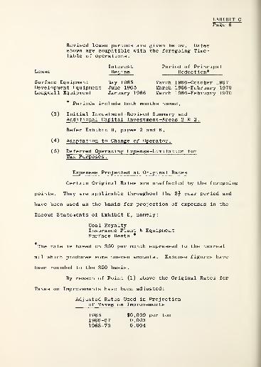
EXHIBIT C
Revised lease periods are given below. Datesshown are compatible with the foregoing Time-table of operations.
Interest Period of PrincipalLease Begins Reduction*
Surface Equipment May 1965 March 1966-October 1967Development Equipment June 1965 March 1966-February 1970Longwall Equipment January 1966 March 1966-February 1970
* Periods include both months named.
(3) Initial Investment-Revised Summary andAdditional Capital Investment-Areas 2 & 3.
Refer Exhibit B, pages 2 and 6.
(.4) Adaptation to Change of Operator.
(5) Deferred Operating Expense-Limitation forTax Purposes.
Expenses Projected at Original Rates
Certain Original Rates are unaffected by the foregoing
points. They are applicable throughout the 8§ year period and
have been used as the basis for projection of expenses in the
Income Statements of Exhibit E, namely:
Coal RoyaltyInsurance-Plant & EquipmentSurface Rental*
The rate is based on $50 per month expressed to the nearest
mil which produces some uneven amounts. Expense figures have
been rounded to the $50 basis.
By reason of Point (1) above the Original Rates for
Taxes on Improvements have been adjusted:
Adjusted Rates Used in Projectionof Taxes on Improvements
1965 $0,009 per ton1966-67 0.0031968-70 0.004

EXHIBIT CPage 7
Depreciation, Depletion, Equipment RentalReconciliation with Feasibility Study
Annual Depreciation and Depletion charges shown in
the Income Statements of Exhibit E have been computed directly,
using as bases the several investments and the respective
periods over which they are written off (Points (l) and (3)
above) rather than by means of any unit rates. Dates upon
which the various groups of Plant & Equipment representing
initial and later investments will become fully depreciated,
are given in Note 7 to the Balance Sheets of Exhibit G.
In similar manner, leasing costs, separated into
Leased Equipment-Rental (Reduction of Principal) and Leased
Equipment-Interest, have been computed directly from the
basic data (Point (2) above) rather than by means of unit
rates. The schedule of equipment deliveries contained in
Note 14 to the Income Statements of Exhibit E has been used
in determining interest charges prior to March 1966.
It is the purpose of this exhibit to point out and
reconcile differences between Original Rates of the Feasibility
Study and expenses as now projected. For depreciation, deple-
tion and equipment leasing expenses, means to make a direct
comparison of unit rates are lacking. Hence, comparison is
made in another manner.
In the Feasibility Study, page 50, Depreciation and
Depletion are combined into a single item; Contingencies and
Engineering are separate items; Equipment Rental includes both
reduction of principal and interest. In the Income Statements,
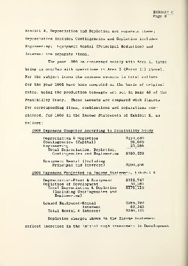
Exhibit E, Depreciation and Depletion are separate items;
Depreciation includes Contingencies and Depletion includes
Engineering; Equipment Rental (Principal Reduction) and
Interest are separate items.
The year 1966 is concerned solely with Area 1, there
being no overlap with operations in Area 2 (Point (1) above)
.
For the subject items the expense amounts in total dollars
for the year 1966 have been computed on the basis of original
rates, using the production tonnages set out in page 48 of the
Feasibility Study. These amounts are compared with figures
for corresponding items, combinations and separations con-
sidered, for 1966 in the Income Statements of Exhibit E, as
follows
:
1966 Expenses Computed According to Feasibility Study
Depreciation & Depletion $110,640Contingencies (Capital) 26,600Engineering 23,288
Total Depreciation, Depletion,Contingencies and Engineering $160,528
Equipment Rental (IncludingPrincipal and Interest) $390,856
1966 Expenses Projected in Income Statement, Exhibit E
Depreciation-Plant & Equipment $125,747Depletion of Development 50,363
Total Depreciation & Depletion $176,110(Including Contingencies andEngineering)
Leased Equipment-Rental $285,780Interest 60,343
Total Rental & Interest $346,123
Depletion charges shown in the Income Statement
reflect increases in the initial cash investment in Development
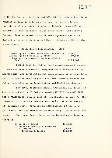
EXHIBIT CPage 9
of $9,000 for Core Drilling and $28,000 for Engineering (Refer
Exhibit B, page 2, Additions Included in Revised Invest-
ment Summary) - a total increase of $37,000. Some 40%, or
$14,800, of this increase is contained in the 1966 expense
figure. This increase, which is due to present revisions,
did not enter into the Original Rates. Comparing the totals
shown above
:
Depletion & Depreciation - 1966
According to Income Statement, Exhibit E $176,110According to Feasibility Study 160, 528
Increase as compared to FeasibilityStudy $ 15, 582
Noting that one mil on the tonnage involved amounts
to $568 and that a number of Original Rates (rounded to the
nearest mil) are involved in the computation, it is considered
that the Feasibility Study and the 1966 Income Statement are
fully reconciled as to Depreciation and Depletion charges.
For 1966, Equipment Rental (Principal and Interest)
has been reduced by $3,503 per month ($37,110 less $33,607).
Refer Feasibility Study, page 51, and Exhibit B, page 7. The
interest rate has been reduced from 10% to 5% on $1,206,855
of equipment cost. Payments in 1966 include 10 months at
full rental and two months of interest only. Refer Point (2)
above. The reduction to be expected in equipment leasing
costs is:
10 Months @ $3,503 $35,0302 Months @ 5/12% per month on
$1,206,855 10,057Expected Reduction $45,087

EXHIBIT CPage 10
Comparing the totals previously shown:
Equipment Leasing Costs
According to the Feasibility Study $390,856According to Income Statement, Exhibit E 346, 123Decrease as compared to Feasibility Study $ 44,733
It is considered that the Feasibility Study and the
1966 Income Statement are fully reconciled as to Equipment
Leasing Costs.
Depreciation, Depletion and Leasing Costs are major
items among overhead expenses. Revisions affecting these items
have been made which have the effect for 1966 of reducing Leasing
Costs by $44,733 and increasing Depreciation & Depletion by
$15,582, a net reduction of $29,151. The latter amount is 3.5%
of the $835,811 total Overhead Expense projected for the year
1966 in Exhibit E. A reduction of this magnitude is of no great
significance to the project as a whole.
Adaptation of Overhead Expense to Change of Operator
It was originally contemplated that operation of the
Demonstration Mine would be carried on by an existing firm well
established in the business of coal mining. As presently con-
ceived, operations will be conducted by a new company organized
for the purpose. This change (Point (4) above) has been taken
into account in projecting overhead expenses in the Income
Statements of Exhibit E, as follows:
Sales - As originally conceived, sales were to be the province
of the sales organization of the operator whose established
sales contacts would be adequate for the purpose. Sales expense,
accordingly, was treated as an overhead expense item for which
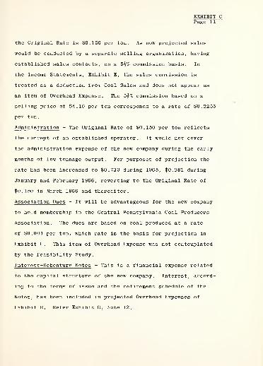
EXHIBIT CPage 11
the Original Rate is $0,150 per ton. As now projected sales
would be conducted by a separate selling organization, having
established sales contacts, on a 5§% commission basis. In
the Income Statements, Exhibit E, the sales commission is
treated as a deduction from Coal Sales and does not appear as
an item of Overhead Expense. The 5j% commission based on a
selling price of $4.10 per ton corresponds to a rate of $0.2255
per ton.
Administration - The Original Rate of $0,150 per ton reflects
the concept of an established operator. It would not cover
the administration expense of the new company during the early
months of low tonnage output. For purposes of projection the
rate has been increased to $0,730 during 1965, $0,291 during
January and February 1966, reverting to the Original Rate of
$0,150 in March 1966 and thereafter.
Association Dues - It will be advantageous for the new company
to hold membership in the Central Pennsylvania Coal Producers
Association. The dues are based on coal produced at a rate
of $0,004 per ton, which rate is the basis for projection in
Exhibit E. This item of Overhead Expense was not contemplated
by the Feasibility Study.
Interest-Debenture Notes - This is a financial expense related
to the capital structure of the new company. Interest, accord-
ing to the terms of issue and the retirement schedule of the
Notes, has been included in projected Overhead Expenses of
Exhibit E. Refer Exhibit G, Note 12.

EXHIBIT CPage 12
Deferred Operating ExpenseLimitation for Tax Purposes
The several kinds of equipment which contribute
to Deferred Operating Expense are listed in the schedule in
page 50 of the Feasibility Study. This equipment requires
periodic expenditures for major overhaul and replacements in
amounts ranging from about $15,000 to more than $200,000
per occurrence according to the kind of equipment involved.
Intervals between occurrences run from 2 years or less to
6 years for the different kinds of equipment. (Refer Foot-
notes (l)-(5) to the same schedule in page 50 of the Study).
Rates shown in the schedule spread the expenditures over
their corresponding periods on a tonnage basis. By this
levelling of peaks and valleys, widely ranging annual expend-
itures are expressed as averages which remain stable.
For example, if a certain kind of equipment required
an expenditure of $100,000 every four years, at normal opera-
ting levels, Deferred Operating Expense for that equipment
would be $25,000 per year. Actual expenditure would be zero
for three years and $100,000 in the fourth year. For purposes
of comparison and the viewing of expense on a long term basis
Deferred Operating Expense figures are more useful than the
widely ranging annual figures.
When computed at the Original Rates of the Study,
total Deferred Operating Expense for the year 1966 amounts to
$149,132. In the Income Statement, Exhibit E, the actual

EXHIBIT CPage 13
expenditure listed as Deferred Operating Expense for the year
1966 is $50,200. It will be understood that in different ways
both figures are proper statements of the expense. Figures in
the Income Statement are projected actual expenditures, not
deferred expense. The caption, Deferred Operating Expense,
has been retained to indicate that the item bears some relation
to the like named item in the Feasibility Study.
By treating periodic expenditures as averages over
their respective periods, Deferred Operating Expense has the
effect of bringing forward into earlier years substantial
amounts of expense for which the actual outlay of funds will
be made in later years. This treatment of expense is inadmis-
sible for Federal Income Tax purposes (Point (5) above) . The
actual expenditures are fully allowable as expense in the year
of occurrence.
Annual expenses shown as Deferred Operating Expense
in the Income Statements of Exhibit E are total actual expend-
itures projected on the basis of rates which take account of
both the periodicity and differing amounts of expenditures
relating to the several sources of deferred expense cited in
page 50 of the Feasibility Study. As would be expected the
rates vary widely from year to year. The rate for any year is
applied to the total tonnage of coal produced during the year.
The rates used are listed on the following page.

EXHIBIT CPage 14
Deferred Operating Expense Rates By Years
Dollars Per Ton
19651966 $0,0871967 0.1201968 0.0901969 0.0821970 0.5851971 0.1701972 0.2501973 0.115

EXHIBIT D
o o o
o oolo ooolo ooolo ooolo ooooo oo o oooo ooo o ooo o oooor» oooloo o to tol ^ oooo]'* ^oooolo to to to to'
1
n& 3£ S8S SS8 SSS S
>,oo o o 2&3ot3
£3 §35 S33 3 3 3 3 «-H ST35g'
78 £3 833 833 333 3 3 8 3
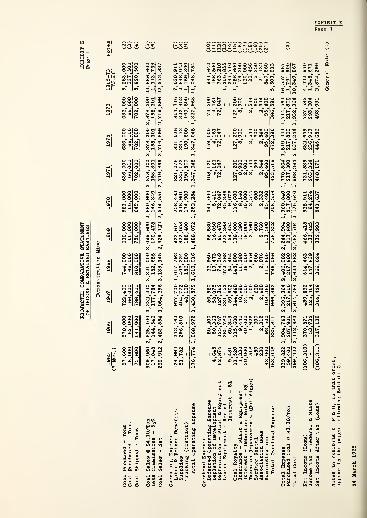
eg
o o o
1
o co
899
22,572,837
716
7,030,911
452
2,848,043
800
1,169,800
968
11,048,754
200
941,640
161
166,500
047
763,210
1,206,855
247,710
200
1,056,600
900
79,300
160,000
544
20,456
600
5,250
544
21,132
400
840,560
CO t-O
\ 11J I
57,600
578,000
722,400
744,000
690,000
583,000
636,000
636,000
636
18,000
63
,
000
66,000
66,000
66,000
66,000
66,000
66,000
66
75,600
641,000
788,400
810,000
756,000
649,000
702,000
702,000
702
o o s ss§ oo o -if- oo •*o-i<o•* ©to-* oo i< o -*oo OrHoi i no) i miflmt
en * o 3 ES I
oo
en rnmo
en t- t» o00 OH(. o o o * © •* o* cm id <* o o o •* o -"f oo -HrtOi i wsiomiomrf
<o -vo
pIS
O -I
1
1ooo
p292,912
2,483,554
3,054,656
3,138,345
2,929,122
2,514,551
2,719
124,992
772,462
977,700
1,017,792
922,614
758,483
821
51,782
296,510
404,772
406,224
377,058
318,901
335
48,100
186,000
188,400
174,900
190
176,774
1,068,972
1,430,572
1,610,016
1,488,072
1,252,284
1,347
50,200
86,580
66,960
56,580
341,000
108
4,645
50,363
58,075
19,473
16,050
5,411
4
62,874
125,747
127,362
78,569
80,470
72,047
72
285,780
331,153
272,268
272,268
45,386
9,481
60,343
59,902
54,454
54,454
9,076
11,520
115,600
144,480
148,800
138,000
116,600
127
1,330
9,440
10,890
11,390
11,390
8,160
8
30,000
40,000
34,000
26,000
18,000
10,000
2
518
1,926
2,100
2,976
2,760
2,544
2
450
600
600
600
600
600
230
2,312
2,890
2,976
2,760
2,332
2
42,000
93,500
108,360
111,600
103,500
95,400
95
<o oo
oo" oVO (0 rH
| SB
to ooo
IN -*0en too
en co es
CO oo
oo cmo
O 00t>
O H IN
CM O
s
uSS.g H^
t3 "S ' **•*K
S.-S 8 « Saoo)t/iT3 ©ail «ti ^ a ao
1*3 "i -g:i
S33EH
saltsUOOOJOO o

01 O|0)|
O Of.
« it s a (do
31 Hi S
'a as
o«o g <j>
S1d< -o o eM
l Sg
se J Mfeo. * o < m
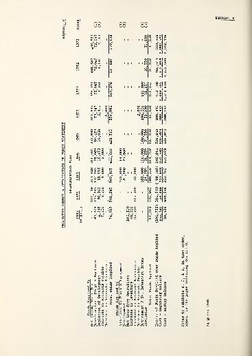
o o^
n 001
8 ««.ooloono »
127,362
78,569
58,075
19,473
4,000
2,000
503,865
466,666
405,800
64,000
31,000
21,500
30,000 100,000
100,000
31,250
31,250
598,050
216,750
(
94,185)
249,916
444,948
350,763
350,763
600,679
. 2 . , P
i II? * IIK-P a 01 to T3 E->cS!
s s m;
3 o a w
" -^ 5 3 S S S
kSiSmS <3i£iSiSiS$Q £ <S 3

* O O '
* o" o"
coSo o
j)Too"o*rt"o m •* o !j
so
00°^s 8
rH OO O 2 o
IS 3" U)
I
o
ao>
H " **. *.
p O 00 ., 00
H» CO
© N eg eg
1 o 83 5 "
0) 0)
r-T H h
oo o m
H H " *"V
o 5 O ego oo~
H H H
o oO CO
o°
" 28 ss*
o oo o o
O Oo"o
* * o
o o OO) 05 »lo 5 O ej
o"
TP lO H eg ro CO
O ooo O CO * ®
o"o o eg Om w M C mo o
|o
§ o
§§*
eg eg N
I s3S
S 3 o is a&«
J.2
I I|3

NotesPage 1
Projected Comparative Statementof Income and Retained Earnings
Demonstration Mine
Notes
(1) General Note. The production, sales and expensefigures appearing in this Statement have been takenor derived from other exhibits of this Supplement,notably Exhibits B, C, and D, or from the FeasibilityStudy. These sources are cited, where appropriate, inthe Notes to the Statement
.
Figures have been carried out to the last dollaras a matter of convenience in proving computations.Extraordinary precision of projection is not implied.A column containing totals for the 8^ year operatingperiod has been included to permit the operation ofthe Demonstration Mine to be viewed as a whole.
(2) Coal Production. Production tonnages shown here aretaken from Exhibit D, Timetable of Projected Operationsand Production.
(3) Coal Purchased and Purchased Coal
.
It is projectedthat strip coal will be purchased, from others workingthe upper coal seams on the same property, at a priceof $3.30 per ton, on the following basis:
Average Tons PerWorking Day
Period Clean Coal Basis
1965 150January-February 1966 200March 1966 onward 300*
* Refer Feasibility Study, page 49, paragraph 2.
(4) Coal Shipped. No appreciable storage of coal is con-templated. Shipments account for all coal producedand purchased.
(5) Coal Sales. Coal shipments, shown in the precedingline, sold at a price of $4.10 per ton, produce CoalSales in the amounts listed. At $4.10 per ton C-primecoal is competitive with residual oil on the EasternSeaboard. Refer Feasibility Study, pages 62 and 63.

NotesPage 2
(6) Sales Commission. It is proposed that a sales com-mission amounting to 5^% of coal sales be paid tothe selling agency handling the sale of coal. ReferExhibit C, Section II, Overhead Expense.
(7) Labor and Fringe Benefits. Labor costs shown in thisstatement have been obtained by the separate computa-tion of the labor cost of the coal produced by eachof the operations set forth in Exhibit D, Timetableof Projected Operations and Production, at the unitlabor cost specified for each operation in the tableof Operating Expense Rates contained in page 3 ofExhibit C, and the summation by years of the separatelycomputed costs. For the elements which make up laborcost refer Feasibility Study, page 49, Labor and Asso-ciated Expenses.
(8) Supplies
.
A list of the items of expense which makeup the cost of supplies is displayed in the tabulationof Estimated Costs Per Ton contained in page 49 of theFeasibility Study. Supply costs shown in this Statementhave been computed and summed using the data ofExhibits C and D in the same manner as for labor costs.Refer Note 7 above.
(9) Trucking. Surface transport by truck of coal frommine to shipping point is projected for operations inAreas 2 and 3. Trucking costs shown are based on unitcosts displayed in page 3 of Exhibit C.
(10) Deferred Operating Expense. Deferred Operating Expenseas used here refers to substantial periodic expenditures,over and above the expense of routine maintenance andrepair, for major overhaul, rebuilding, parts renewals,and moving of underground equipment . The nature of theexpenditures and their different timing for differentkinds of equipment are set forth in the schedule ofOverhead Expense and Footnotes (l)-(5) thereto appear-ing in page 50 of the Feasibility Study.
This Income Statement shows the yearly totals ofsuch expenditures taken as they are projected to occur.The totals vary widely from year to year for the reasonthat individual expenditures for the several kinds ofequipment differ both in size and in frequency of occur-rence. Refer Exhibit C, Section II, Overhead Expense,for discussion of Deferred Operating Expense.
(11) Depletion of Development. Refer Exhibit G, Note 8,wherein the makeup of Development Costs totalling$166,500 is set forth and referenced and the basisfor Depletion charges is stated. It will be noted

(11) (Continued)
that the total amount of Depletion charges appearingin the Income Statement is $166,500.
(12) Depreciation-Plant & Equipment. A statement of invest-ments, totalling $763,210, made in Plant & Equipment,and the periods of time over which the various portionsof the resulting assets are to be depreciated, are setforth and referenced in Exhibit G, Note 7. Corres-ponding Depreciation charges are shown in the IncomeStatement. With the final depreciation charge shownin 1973 all Plant & Equipment will have been fully de-preciated. All depreciation is on a straight linebasis over the time periods involved. It will be notedthat the total amount of Depreciation charges appearingin the Income Statement is $763,210.
(13) Leased Equipment-Rental. Monthly rental payments onaccount of principal (but not including interest), timedaccording to the periods of principal reduction pro-jected for the three groups of leased equipment make upthe annual amounts shown as Leased Equipment-Rental, inthe Income Statements. The total of such amounts duringthe operating period is $1,206,855. Refer schedule ofLease Projections, Exhibit B, page 7, and Exhibit C,
page 5.
(14) Leased Equipment-Interest. Carrying charges (Interest)on leased equipment are projected to begin accordingto the following schedule of equipment deliveries. Theamounts shown in the schedule are the accumulated deliver-ies as of each month for each lease.
Amount of Principal - Cost ofMonth in Which Equipment Delivered
Interest Is Surface Underground LongwallPayable Equipment Equipment Equipment
May 1965 $ 17,900June 196 5 100,040 $ 7,400July 1965 108,775 34,390August 1965 108,775 236,152September 1965 117,775* 238,652October 1965 - 312,202November 1965 - 312,202December 1965 - 325,670*January 1966 - $763,410*
Full amount of Lease, delivery completed.
(14) (Continued)
Monthly interest payments, at an annual rate of5% on the principal amounts shown during the deliveryperiods and thereafter on the full amount of eachlease to the end of the lease period, make up theannual amounts, shown as Leased Equipment-Interest,which appear in the Income Statement.
Refer schedule of Lease Projections, Exhibit B,
page 7, and related discussion.
(15) Coal Royalty. Royalty payments, at a rate of $0,200per ton of coal produced, according to the terms ofthe coal lease, are shown as annual amounts in theIncome Statement. Refer Feasibility Study, OverheadExpense, page 50.
(16) Insurance-Plant & Equipment
.
Annual insurance cost isprojected on the basis of the unit rates set forth inthe Feasibility Study, Overhead Expense, page 50, andthe operations listed in Exhibit D of this Supplement.
(17) Interest-Debenture Notes. Interest on the Seven Year8% Debenture Notes is projected in accordance with thedate of issue and the retirement schedule appearing inNote 12 to Exhibit G, Balance Sheets.
(18) Taxes on Improvements (Buildings)
.
Annual taxes of thischaracter are projected on the basis set forth inExhibit C, Section II, Overhead Expense.
(19) Surface Rental
.
Annual surface rental is projectedat a rate of $50 per month during the construction andoperating periods shown in Exhibit D of this Supplement.
(20) Association Dues. Dues for membership in the CentralPennsylvania Coal Producers Association are projectedat a rate of $0,004 per ton of coal produced. ReferExhibit C, Section II, Overhead Expense.
(21) Administration
.
Administration Expense is projected onthe basis of rates set forth in the Feasibility Study,Overhead Expense, page 50, beginning with March 1966;with some upward adjustment of rates for the periodJuly 1965-February 1966. Refer Exhibit C, Section II,Overhead Expense.

EXHIBIT E
Notes
(21) (Continued)
Administration includes:Salaries -Of f icersSalaries-Purchasing, Stenographic, 50% of
EngineeringOffice Rent, Utilities and TelephoneStationery and PrintingTravel ExpenseContributionsDirectors Fees and ExpensesJanitor Service
(22) Dividends Paid. It is projected that cash dividends atan annual rate of 25% on Capital Stock will be paid in1967 and later years.
(23) Income Deductions and Tax Incidence. Permissible de-ductions and allowances for Federal income tax purposesare Loss Carry Forward and Depletion Allowance. In theIncome Statement operating loss from 1965 is taken as adeduction in 1966. Depletion Allowance is taken in 1966and later years
.
Depletion Allowance is defined as an amount equalto 10% of Gross Sales of coal produced but not morethan 50% of Net Income Before Tax.
In order to exhibit the basis on which the Appli-cable Depletion Allowance is taken the following havebeen included in the Statement
:
Gross Sales of Coal Produced computed ata price of $4.10, purchased coal excluded.
A - 10% of Gross Sales of Coal Produced(As above)
B - 50% of Net Income (Before tax)
.
As indicated by asterisks (*) "B" is the limiting amountfor the years 1966-70 and "A" for the years 1971-73.
Federal income tax rates for 1965 are: 22% on the
first $25,000 and 28% on the balance of taxable income.
Federal Income Tax has been computed at these rates on
the amounts shown as Income Subject to Federal Income Tax.
(24) Pennsylvania Income Taxes. Pennsylvania Income Tax is
computed at a rate of 6% on the amounts shown as Net
Income (i.e., Net Income before Tax). Previous losses
are not deductible.

Projected Source 8c Application of Funds Statement
Demonstration Mine
(1) Depreciation-Plant & Equipment. Refer Exhibit E,
Note 12, and Exhibit G, Note 7.
(2) Depletion of Development. Refer Exhibit E, Note 11,and Exhibit G, Note 8.
(3) Additions to Plant & Equipment and Development
.
Refer Exhibit B, Page 6, Additional CapitalInvestment-Areas 2 & 3.
(4) Retirement 7 Year Debenture Notes. Refer Exhibit G,Note 12.
(5) Dividends. Refer Exhibit E, Note 22.

EXHIBIT GNotesPage 1
Projected Comparative Balance Sheets
Demonstration Mine
(1) General Note
(a) It is intended that these projections shall beconservative. For simplicity they are made on thepremise that operations of the Demonstration Mine willbe conducted on a current cash basis with respect toall operating and overhead expenses, taxes and relatedobligations, these being met as they arise withoutprepayment or accrual . Thereby the usual array ofprepaid and accrued utems is eliminated from the balancesheets. Such items convey no essential informationabout an enterprise unless the accruals are so largerelatively as to suggest financial difficulty.
As compared with a balance sheet in which theseitems appear their elimination has the following effect.Current assets and current liabilities are somewhatreduced - both to the same extent. Net working capitalis unchanged. If, as is usually true, the accruedobligations exceed the prepaid items the cash balanceis reduced by the amount of such excess. Other accountsare not affected.
The simplified balance sheets do not render theprojections less conservative than if made on an accrualbasis. To the extent that projected cash balances arereduced when operations are put on a cash basis, theprojections are made more conservative.
(b) These projections are concerned with the Demonstra-tion Mine up to the conclusion of operations in Area 3.Since no forecast is made of the course to be taken bythe operating company beyond that time the projectionsterminate with the condition existing at the end of 1973prior to any change that might then occur.
(2) Balance Sheet at June 30, 1965. The Balance Sheet atJune 30, 1965 displays, with some approximation, the con-dition of the mining enterprise just prior to the beginningof Butt Entry Development operations in Area 1. The con-dition shown is that which would exist if all constructionand development work were completed. According to opera-ting projections the construction would not be entirelycompleted for another two months (Refer Feasibility Study,page 50, last paragraph) and some $25,000 of Developmentexpenditure would remain to be made in January and

EXHIBIT GNotesPage 2
(2) (Continued)
February 1966. (Refer Feasibility Study, last itemon page 58 - Development) . This approximation is madein order to bring the figures showing available capitaland the initial expenditure thereof together in asingle statement uncomplicated by operating results.
For detail on particular items refer to noteslisted in the column to the right of the 1973 BalanceSheet.
(3) Balance Sheet at December 31, 1970. The 1970 BalanceSheet reflects only 11 months of mining operation.Operations will be suspended one month to allow over-haul of Longwall Roof Supports. (Refer Exhibit D) .
(4) Cash. The cash balance shown at June 30, 1965 is theresidue of initial capital after investment in the otherassets listed. The capital structure has been propor-tioned to allow a fund of this magnitude to provideworking capital during the period in which operationswill be conducted at a loss, with some margin of safety.
Beginning in 1966 operations would become suffi-ciently profitable to meet requirements for increasedworking capital, provide for debt service, and generateadditional cash in excess of the amount that would berequired for carrying on operations. It is beyond thescope of these projections to forecast the dispositionof excess cash. Therefore it appears as an accumulationin the cash account
.
(5) Accounts Receivable. Accounts Receivable are projectedon the basis of an average age of approximately 20 days,coal sales considered.
(6) Inventory
.
(a) The omission of a coal inventory is intentional.No stockpiling of coal is contemplated. Operations asprojected would limit the coal on hand to the contentof the 800 ton raw coal silo ahead of the cleaning plantand such clean coal as had accumulated for the nextshipment. The total could approximate 5,000 tons atmaximum, approach zero at minimum, and would be subjectto rapid fluctuation. It is disregarded in these pro-jections .
(b) The small initial inventory of Spare Parts & Replace-ment Units is adequate for the routine maintenance and
EXHIBIT G
(6) (Continued)
repair of the development equipment which would operateduring 1965 operations. For 1966 and later years it isincreased to accommodate longwall equipment as well.The inventory shown does not provide for major replace-ments that are periodically required by several typesof equipment. Materials for such purposes would bepurchased as and when required for each such occurrence
.
(7) Plant & Equipment. The amounts shown as Plant & Equip-ment (At Cost) have been adjusted to reflect additionsdue to further investment and deletion of those assetswhich become fully depreciated prior to 1973. Thoseremaining on record at the end of 1969 become fullydepreciated as of December 31, 1973 but are not deleted.Accumulated Depreciation has also been adjusted to matchthe deletion of assets. Adjustments are as follows:
Plant and AccumulatedEquipment Depreciation
Balance Sheet December 31,1966 293,41o( i) 188,621Additions - 1967 367,900(ii) 127,362
37,900( 11:L )
699,210 315,983Deletions - 1967 293,4ip ( i ) 293,410
Balance Sheet December 31,1967 405,800 . 22,573Additions - 1968 64,000 UvJ 78,569
Balance Sheet December 31,1968 469,800 101,142Additions - 1969 80,470
469,800 181,612Deletions - 1969 37,900
^111 > 37,900
Balance Sheet December 31,1969 431, 900 (v) 143,712
(i) Original Plant & Equipment-Area 1, Fullydepreciated October 31, 1967. Refer Analysisof Initial Cash Investment, Exhibit B, page 5.
(ii) Plant & Equipment-Area 2. Also used for Area 3.Remains in use through 1973. Refer AdditionalCapital Investment, Area 2, Total (b) , Exhibit B,page 6.
(iii) Plant & Equipment-Area 2. Fully depreciatedJune 30, 1969. Refer Additional Capital Invest-ment, Area 2, Total (a), Exhibit B, page 6.
(iv) Plant & Equipment-Area 3. Remains in use through1973. Refer Additional Capital Investment,Area 3, Exhibit B, page 6.

EXHIBIT G
Notes
(7) (Continued)
(v) Consists of (ii) and (iv)
.
Annual Depreciation charges are shown and noted in theIncome Statements of Exhibit E.
(8) Development-Net of Depletion. Expenditures for thework and services termed Development constitute invest-ment made in anticipation of and necessary for theextraction of coal from a property. Development ex-penditures are capitalized when made and written offover the operating life of the property by means ofDepletion charges to overhead expense.
Initial and later expenditures for Development,detailed in the references, are:
Developmen t Reference
Initial Cash Investment $114,000 (a)Additional Investment-Area 2 31,000 (b)Additional Investment-Area 3 21, 500 (b)
Total $166 , 500
References(a) Analysis of Initial Cash Investment, Exhibit B,
page 5.(b) Additional Capital Investment-Areas 2 and 3,
Exhibit B, page 6.
The initial investment appears in the BalanceSheet of June 30, 1965. Amounts shown at December 31,1965 and for later years are the undepleted year-endDevelopment balances which are equal to: (Total Invest-ment in Development to date) minus (Accumulated Depletionto date). The Additional Investments for Areas 1 and 2,projected as occurring in April 1967 and November 1968respectively, have been added as of the date of occur-rence to the then existing undepleted balance. AnnualDepletion charges are shown and noted in the IncomeStatements of Exhibit E.
(9) Recoverable Deposits. A list of these deposits appearsas Analysis of Recoverable Deposits in page 4 ofExhibit B with references indicating their purposes. Thedeposits are recoverable either by refund at the con-clusion of operations or in the form of credits applicableto coal royalty payments in the last months of operations.
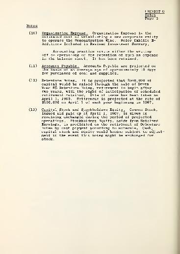
Notes
EXHIBIT GNotesPage 5
(10) Organization Expense. Organization Expense is theestimated cost of establishing a new corporate entityto operate the Demonstration Mine. Refer Exhibit B-Additions Included in Revised Investment Summary.
Accounting practice admits either the writingoff to operations or the retention of such an expensein the balance sheet. It has been retained.
(11) Accounts Payable. Accounts Payable are projected onthe basis of an average age of approximately 10 daysfor purchases of coal and supplies.
(12) Debenture Notes. It is projected that $500,000 ofcapital would be raised through the sale of SevenYear 8% Debenture Notes, retirement to begin aftertwo years, with the right of anticipation of scheduledretirement retained. Date of issue has been taken asApril 1, 1965. Retirement is projected at the rate of$100,000 on April 1 of each year beginning in 1967.
(13) Capital Stock and Stockholders Equity. Common Stock,issued and paid up at April 1, 1967, is shown asremaining unchanged during the period of projectedoperations. Stockholders Equity, aside from RetainedEarnings, is predicated on the retirement of DebentureNotes by cash payment according to schedule. Cash,capital stock and equity would become subject to adjust-ment in the event that notes might be exchanged forstock.

Proposed Demonstration Mine
East of Windber, Pennsylvania
Number Title
A- 1-32 Right of Way Across McQuaide Surface
B- 6-11 Equipment Detail - Head Stable
B- 6-12 Equipment Detail - Tail Stable
C-10-25 General Flow Diagram
C-10-32 Surface Plant Layout Showing ProposedSiding Extension
C-10-33 Strata and Seam Data
C-10-34 Projection - C' Seam
C-10-35 Underground Equipment
C-10-38 Mining Plan
C-10-39 Surface Layout

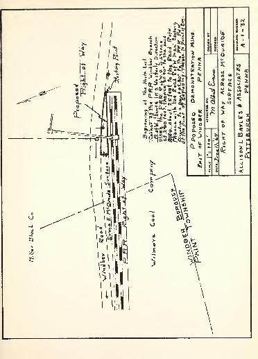
!si i

////'////.'////'////S//////////S.:
f «!
f i;i
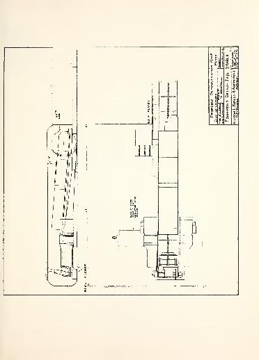
M
^3
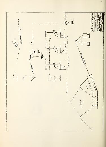

Illl
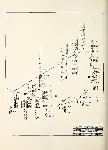
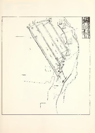
a

DOiMOMiJL:I


S*-ATESO***
PENN STATE UNIVERSITY LIBRARIES
AOOOO?!^^15