Feasibility of semi-solid die casting of ADC12 aluminum · PDF file ·...
7
Feasibility of semi-solid die casting of ADC12 aluminum alloy S. JANUDOM 1 , T. RATTANOCHAIKUL 1 , R. BURAPA 2 , S. WISUTMETHANGOON 3 , J. WANNASIN 1 1. Department of Mining and Materials Engineering, Faculty of Engineering, Prince of Songkla University, Hat Yai, Songkhla, 90112, Thailand; 2. Department of Industrial Engineering, Faculty of Engineering, Rajamangala University of Technology Srivijaya, Songkhla, 90000, Thailand; 3. Department of Mechanical Engineering, Faculty of Engineering, Prince of Songkla University, Hat Yai, Songkhla, 90112, Thailand Received 13 May 2010; accepted 25 June 2010 Abstract: The feasibility of semi-solid die casting of ADC12 aluminum alloy was studied. The effects of plunger speed, gate thickness, and solid fraction of the slurry on the defects were determined. The defects investigated are gas and shrinkage porosity. In the experiments, semi-solid slurry was prepared by the gas-induced semi-solid (GISS) technique. Then, the slurry was transferred to the shot sleeve and injected into the die. The die and shot sleeve temperatures were kept at 180 °C and 250 °C, respectively. The results show that the samples produced by the GISS die casting give little porosity, no blister and uniform microstructure. From all the results, it can be concluded that the GISS process is feasible to apply in the ADC12 aluminum die casting process. In addition, the GISS process can give improved properties such as decreased porosity and increased microstructure uniformity. Key words: ADC12 aluminum alloys; semi-solid die casting; gas induced semi-solid (GISS); rheocasting 1 Introduction For many years aluminum parts have been used in several applications such as automotive, electronic, aerospace, and construction fields. These parts are generally produced in a large quantity by the high pressure die casting process. Several advantages of die casting process have been realized such as high production rate and the ability to form small complex parts. The die casting process involves the injection of liquid aluminum into a die cavity under high pressures. The metal stream “sprays” into the die cavity, causing metal reaction and air entrapment inside the casting. Therefore, the final parts have a structure which is full of gas bubbles and oxide inclusions. Furthermore, pressure die casting parts typically cannot be machined, anodized, welded, and heat treated because of these defects[1−4]. To improve the quality and properties of the die casting process, semi-solid metal technique has been introduced. A lot of semi-solid die casting studies have reported that using semi-solid die casting helps to improve the properties and increase the quality of die casting parts[5−7]. Semi-solid metal forming using the rheocasting route can provide higher viscosity of the fluid. With the higher viscosity, less turbulent flow could be obtained, which helps to reduce air porosity and oxide inclusions during the die filling[5−7]. In addition, a rheocasting process can be easily applied with the conventional die casting process because the die casting machine only requires minor modifications[8]. Many research studies have shown successes in the semi-solid die casting with a rheocasting process[7−12]. However, most work have used the A356, A357, and ADC10 aluminum alloys. Despite ADC12 is used widely in the die casting industry, no complete research about semi-solid forming of this aluminum alloy has been published yet. The benefits of ADC12 aluminum alloy are good fluidity, excellent castability and high mechanical properties. In contrast, it is easy to have turbulent flow, which causes porosity defect, and it cannot normally be heat treated because of the surface blister and the pore expansion at high temperatures[13−14]. To solve the problems of ADC12 aluminum alloy, a semi-solid die casting process is selected to study in this work. The main objectives of this research are to study the feasibility of 1) the semi-solid processing of ADC12 Corresponding author: J. WANNASIN; Tel: +66-74-287-312; E-mail: [email protected]; [email protected] DOI: 10.1016/S1003-6326(09)60370-8
Transcript of Feasibility of semi-solid die casting of ADC12 aluminum · PDF file ·...
Feasibility of semi-solid die casting of ADC12 aluminum alloy
S. JANUDOM1, T. RATTANOCHAIKUL1, R. BURAPA2, S. WISUTMETHANGOON3, J. WANNASIN1
1. Department of Mining and Materials Engineering, Faculty of Engineering, Prince of Songkla University,
Hat Yai, Songkhla, 90112, Thailand; 2. Department of Industrial Engineering, Faculty of Engineering, Rajamangala University of Technology Srivijaya,
Songkhla, 90000, Thailand; 3. Department of Mechanical Engineering, Faculty of Engineering, Prince of Songkla University,
Hat Yai, Songkhla, 90112, Thailand
Received 13 May 2010; accepted 25 June 2010
Abstract: The feasibility of semi-solid die casting of ADC12 aluminum alloy was studied. The effects of plunger speed, gate thickness, and solid fraction of the slurry on the defects were determined. The defects investigated are gas and shrinkage porosity. In the experiments, semi-solid slurry was prepared by the gas-induced semi-solid (GISS) technique. Then, the slurry was transferred to the shot sleeve and injected into the die. The die and shot sleeve temperatures were kept at 180 °C and 250 °C, respectively. The results show that the samples produced by the GISS die casting give little porosity, no blister and uniform microstructure. From all the results, it can be concluded that the GISS process is feasible to apply in the ADC12 aluminum die casting process. In addition, the GISS process can give improved properties such as decreased porosity and increased microstructure uniformity. Key words: ADC12 aluminum alloys; semi-solid die casting; gas induced semi-solid (GISS); rheocasting 1 Introduction
For many years aluminum parts have been used in several applications such as automotive, electronic, aerospace, and construction fields. These parts are generally produced in a large quantity by the high pressure die casting process. Several advantages of die casting process have been realized such as high production rate and the ability to form small complex parts. The die casting process involves the injection of liquid aluminum into a die cavity under high pressures. The metal stream “sprays” into the die cavity, causing metal reaction and air entrapment inside the casting. Therefore, the final parts have a structure which is full of gas bubbles and oxide inclusions. Furthermore, pressure die casting parts typically cannot be machined, anodized, welded, and heat treated because of these defects[1−4].
To improve the quality and properties of the die casting process, semi-solid metal technique has been introduced. A lot of semi-solid die casting studies have reported that using semi-solid die casting helps to improve the properties and increase the quality of die casting parts[5−7]. Semi-solid metal forming using the
rheocasting route can provide higher viscosity of the fluid. With the higher viscosity, less turbulent flow could be obtained, which helps to reduce air porosity and oxide inclusions during the die filling[5−7]. In addition, a rheocasting process can be easily applied with the conventional die casting process because the die casting machine only requires minor modifications[8].
Many research studies have shown successes in the semi-solid die casting with a rheocasting process[7−12]. However, most work have used the A356, A357, and ADC10 aluminum alloys. Despite ADC12 is used widely in the die casting industry, no complete research about semi-solid forming of this aluminum alloy has been published yet. The benefits of ADC12 aluminum alloy are good fluidity, excellent castability and high mechanical properties. In contrast, it is easy to have turbulent flow, which causes porosity defect, and it cannot normally be heat treated because of the surface blister and the pore expansion at high temperatures[13−14].
To solve the problems of ADC12 aluminum alloy, a semi-solid die casting process is selected to study in this work. The main objectives of this research are to study the feasibility of 1) the semi-solid processing of ADC12
Corresponding author: J. WANNASIN; Tel: +66-74-287-312; E-mail: [email protected]; [email protected] DOI: 10.1016/S1003-6326(09)60370-8

S. JANUDOM, et al/Trans. Nonferrous Met. Soc. China 20(2010) 1756−1762 1757
aluminum alloy using the gas induced semi-solid (GISS) technique and 2) the semi-solid die casting of a commercial part. 2 Experimental
The material used in this study is commercial ADC12 aluminum alloy. The liquidus temperature of this alloy is 582 °C. The eutectic temperature of this alloy is 572 °C. The chemical composition measured using the optical emission spectrometer (OES) is shown in Table 1. Table 1 Chemical composition of aluminum ADC12 alloy (mass fraction, %)
Si Fe Cu Mn Mg Zn 11.88 0.93 1.75 0.12 0.07 0.78
Ti Cr Ni Pb Sn Al 0.06 0.03 0.11 0.06 0.01 Bal.
2.1 Semi-solid slurry preparation
In this experiment, an ADC12 aluminum alloy was melted in the graphite crucible in an electrical furnace at about 100 °C above the liquidus temperature (~680 °C). Approximately 200 g of the melt was taken from the crucible using a ladle. Next, the nitrogen gas was injected through a graphite diffuser into the ladle when the temperature of the melt was about 590 °C. The times to inject the gas were 5, 10 and 15 s. The schematic diagram of the GISS process is shown in Fig.1. At the varied injection times, the solid fractions were analyzed using the rapid quenching method. The high cooling rates achieved by the copper mold allow the capture of the microstructure at a certain temperature[15−16].
The microstructure of the samples from different rheocasting times was used to calculate the solid fraction. The Photoshop and Image Tool Software were used in the analysis[16].
2.2 Die casting process
The aluminum slurry prepared by the GISS process
Fig.1 Schematic diagram of gas induced semi-solid (GISS) process
was transferred to the die casting machine. This machine has 80 t capacity for the clamping system. The slurry was poured into the shot sleeve kept at the temperature of 250 °C. The plunger forced the slurry into the die at various speeds of 0.05, 0.1 and 0.2 m/s. The die temperature was kept at 180 °C. The schematic diagram of the GISS die casting process is illustrated in Fig.2. In this study, the porosity, surface defect, surface blister, macro- and micro-structure of the samples were investigated. A summary of the parameters used in this study is illustrated in Table 2.
Fig.2 Schematic diagram of GISS die casting process 2.3 Die casting part analysis
The analysis methods are briefly described as follows.
1) Porosity analysis The density of the sample (DL) was measured using
Eq.(1), and Eq.(2) was used to calculate the porosity (η):
water-inwet
dryL mm
mD
−= (1)
S
LS
DDD −
=η (2)
where DS is the standard density of an ADC12 aluminum alloy (2.76 g/cm3); DL is the density from Eq.(1).
2) Surface defect and blistering test Observation of the surface defect of the samples
was conducted after the die casting process. The defects observed in this study were cold shut and blistering defects. The blistering was evaluated after the samples passed the solution treatment at 480 °C for 12 h.
3) Macro defects All the samples were cut at the center as shown in
Fig.3. Next, the samples were ground with the 320, 800, and 1200 grit papers to observe the macro defects.
4) Microstructure uniformity The microstructure at different positions of the
samples was observed using an optical microscope. The samples were cut and obtained from positions A, B, C, and D as shown in Fig.3. The samples were then prepared for metallographic analysis using standard grinding, polishing and etching procedures.
S. JANUDOM, et al/Trans. Nonferrous Met. Soc. China 20(2010) 1756−1762 1758
Table 2 Summary of parameters used in this study
Condition Rheo-casting
temperature/°C Rheo-casting
time/s Gate thickness/
mm Plunger speed/
(m·s−1) Gate velocity/
(m·s−1) Liquid 650 − 1.5 0.20 5.58
SSM1-1 590 5 3 0.20 2.79 SSM1-2 590 5 3 0.10 1.39 SSM1-3 590 5 3 0.05 0.69 SSM1-4 590 10 3 0.20 2.79 SSM1-5 590 10 3 0.10 1.39 SSM1-6 590 10 3 0.05 0.69 SSM1-7 590 15 3 0.20 2.79 SSM1-8 590 15 3 0.10 1.39 SSM1-9 590 15 3 0.05 0.69 SSM2-1 590 5 6 0.20 1.39 SSM2-2 590 5 6 0.10 0.69 SSM2-3 590 5 6 0.05 0.35 SSM2-4 590 10 6 0.20 1.39 SSM2-5 590 10 6 0.10 0.69 SSM2-6 590 10 6 0.05 0.35 SSM2-7 590 15 6 0.20 1.39 SSM2-8 590 15 6 0.10 0.69 SSM2-9 590 15 6 0.05 0.35
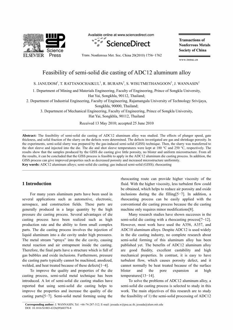
Fig.3 Drawing of increased rheocasting time part 3 Results and discussion 3.1 Semi-solid slurry
From the obtained results, the slurries produced by the conditions of the rheocasting times of 5, 10 and 15 s have the solid fractions of 0.25%, 6.33%, and 13.03%, respectively. The representative microstructures of the quenched samples at different rheocasting times are shown in Fig.4. The micrographs illustrate that amount of the primary α(Al) (white phase) increases with increased rheocasting time. The viscosity of the slurry should be increased when the solid fraction is increased.
It can be concluded that the ADC12 aluminum alloy can be produced into a semi-solid slurry at a desired solid fraction by varying the rheocasting time using the GISS process. 3.2 Die casting process
A representative sample produced by the semi-solid
Fig.4 Representative micrographs of samples at different rheocasting times: (a) 5 s; (b) 10 s; (c) 15 s
S. JANUDOM, et al/Trans. Nonferrous Met. Soc. China 20(2010) 1756−1762 1759
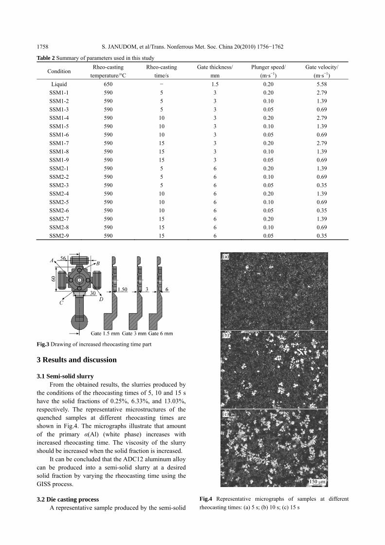
die casting process is shown in Fig.5. The sample consists of three overflows, a runner, and a biscuit. Most samples had complete metal filling in the overflow and good surface finish. Only the samples produced with a higher solid fraction had the cold shut defect as shown in Table 3 and the representative samples with the cold shut defect is shown in Fig.6.
Fig.5 Representative picture of die casting part
The high solid fractions cause the viscosity of the
slurry higher. For the thin gate (3 mm), the high viscosity slurry was difficult to flow into the die so that the metal could not fill the part completely. In addition, the cold shut defect was found because of the shorter solidification time of the higher solid fractions.
3.3 Porosity analysis
The results show that the samples produced by the
Fig.6 Surface defect of casting: (a) Misrun; (b) Cold shut
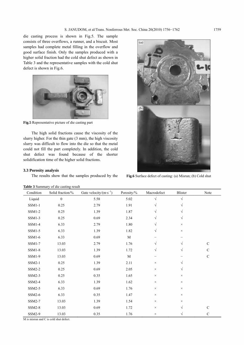
Table 3 Summary of die casting result
Condition Solid fraction/% Gate velocity/(m·s−1) Porosity/% Macrodefect Blister Note
Liquid 0 5.58 5.02 √ √
SSM1-1 0.25 2.79 1.91 √ √
SSM1-2 0.25 1.39 1.87 √ √
SSM1-3 0.25 0.69 2.34 √ √
SSM1-4 6.33 2.79 1.80 √ ×
SSM1-5 6.33 1.39 1.82 √ ×
SSM1-6 6.33 0.69 M − −
SSM1-7 13.03 2.79 1.76 √ √ C
SSM1-8 13.03 1.39 1.72 √ √ C
SSM1-9 13.03 0.69 M − − C
SSM2-1 0.25 1.39 2.11 × √
SSM2-2 0.25 0.69 2.05 × √
SSM2-3 0.25 0.35 1.65 × ×
SSM2-4 6.33 1.39 1.62 × ×
SSM2-5 6.33 0.69 1.76 × ×
SSM2-6 6.33 0.35 1.47 × ×
SSM2-7 13.03 1.39 1.54 × ×
SSM2-8 13.03 0.69 1.72 × √ C
SSM2-9 13.03 0.35 1.76 × √ C M is misrun and C is cold shut defect.

S. JANUDOM, et al/Trans. Nonferrous Met. Soc. China 20(2010) 1756−1762 1760 liquid die casting and the semi-solid die casting processes have the porosity of about 5% and 1.7%, respectively. The porosities of the samples produced by both processes are compared in Fig.7. However, in the semi-solid die casting samples, the result of the porosity of different conditions of gating size and velocity are not significantly different.
Fig.7 Porosity of samples under different conditions
In summary, in the liquid casting, turbulent flow is present, which results in porosity defect in the samples. In contrast, all the semi-solid die casting samples have lower porosity than the liquid die casting due to the less turbulent flow of the slurry. The larger gate also yields less porosity since it gives lower flow velocity. 3.4 Macrodefect analysis
All the samples produced by the semi-solid die casting with the thin gate have shrinkage porosity. In addition, gas porosity is found in the samples produced by the liquid die casting as shown in Table 3. The shrinkage porosity and gas porosity are shown in Fig.8. It can be concluded that the size of the gate has a large effect on the macro defects. The larger gate helps to reduce the turbulent flow and improve the feeding, which reduces the shrinkage porosity. 3.5 Surface blister
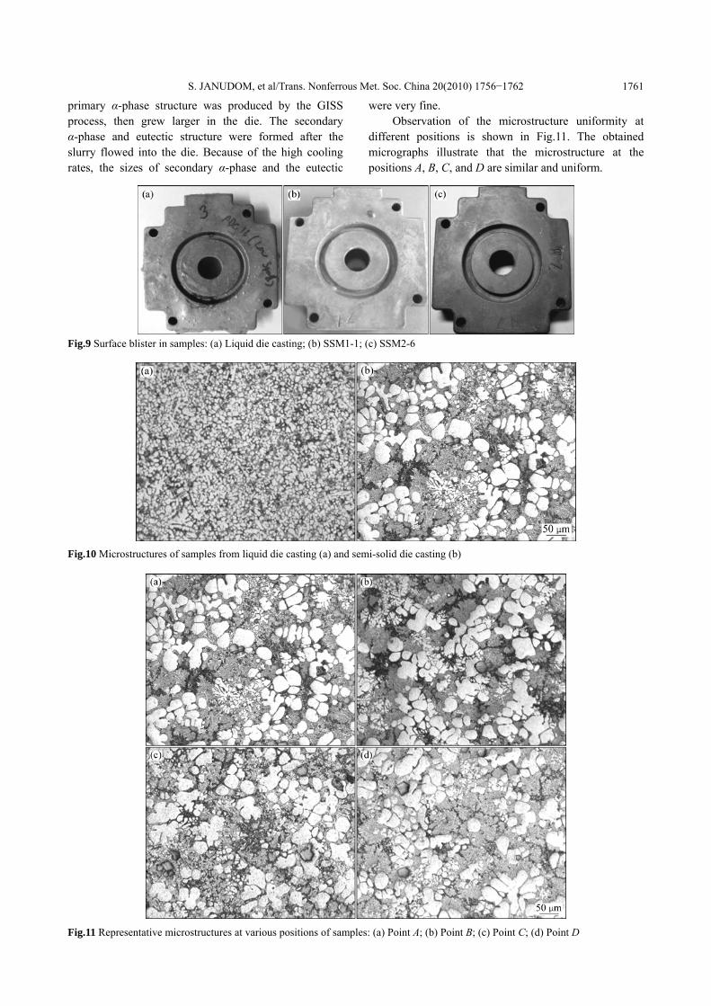
Surface blisters are found after the solution heat treatment process in about half of the samples. This defect is mostly found in the samples produced by the liquid die casting and the semi-solid die casting using a thin gates. In contrast, when the thick gate is employed for the semi-solid die casting, only the samples coded SSM2-8 and SSM2-9 have the defect, as shown in Table 3 and Fig.9.
In summary, the blister defect found in semi-solid die casting can be reduced by increasing the solid fraction and the gate size. However, the solid fraction
Fig.8 Macro views of cross section of samples: (a) Liquid die casting; (b) SSM1-1; (c) SSM2-6 should not be too high because it will be difficult to inject into the die. 3.6 Microstructure analysis
The representative microstructures of the samples produced by liquid die casting and semi-solid die casting are shown in Fig.10. Fine dendritic structure was observed in the samples from the liquid die casting process. However, in the samples from the semi-solid die casting process the microstructure consisted of primary α-phase, secondary α-phase and eutectic phase. The
S. JANUDOM, et al/Trans. Nonferrous Met. Soc. China 20(2010) 1756−1762 1761
primary α-phase structure was produced by the GISS process, then grew larger in the die. The secondary α-phase and eutectic structure were formed after the slurry flowed into the die. Because of the high cooling rates, the sizes of secondary α-phase and the eutectic
were very fine. Observation of the microstructure uniformity at
different positions is shown in Fig.11. The obtained micrographs illustrate that the microstructure at the positions A, B, C, and D are similar and uniform.
Fig.9 Surface blister in samples: (a) Liquid die casting; (b) SSM1-1; (c) SSM2-6
Fig.10 Microstructures of samples from liquid die casting (a) and semi-solid die casting (b)
Fig.11 Representative microstructures at various positions of samples: (a) Point A; (b) Point B; (c) Point C; (d) Point D

S. JANUDOM, et al/Trans. Nonferrous Met. Soc. China 20(2010) 1756−1762 1762 4 Conclusions
1) It is feasible to produce semi-solid ADC12 parts using the gas induced semi-solid process.
2) The porosity and shrinkage defects in the parts can be reduced by increasing the solid fraction of the slurry.
3) Good casting parts of semi-solid die casting need appropriate plunger speeds and solid fractions of the slurry.
4) The microstructure of the produced samples is uniform throughout the casting parts. Acknowledgements
This work is funded by the Royal Golden Jubilee Ph.D. Program (Grant No. PHD/0173/2550), the Thai Research Fund (Contract number MRG5280215) and Prince of Songkla University (Contract No. AGR530031M). The authors would like to thank the Innovative Metal Technology (IMT) team for kind support. References [1] CAMPBELL J. Casting[M]. Oxford: Butterwort-Heinemann, 1991:
1−85. [2] ZHENG J, WANG Q, ZHAO P, WU C. Optimization of
high-pressure die-casting process parameters using artificial neural network [J]. Advanced Manufacturing Technology, 2009, 44: 667−674.
[3] VERRAN G O, MENDESB P K, ROSSIC M A. Influence of injection parameters on defects formation in die casting Al12Si13Cu alloy: Experimental results and numeric simulation [J]. Materials Processing Technology, 2006, 179: 190−195.
[4] HANGAI Y, KITAHARA S. Quantitative evaluation of porosity in aluminum alloy die castings by fractal analysis of spatial distribution of area [J]. Materials and Design, 2009, 30: 1169−1173.
[5] KIRKWOOD D H, SUERY M, KAPPANOR P, ATKINSON H V, YOUNG K P. Semi-solid processing of alloy [M]. New York: Springer, 2009.
[6] FLEMING M C. Behavior of metal alloy in the semi-solid state [J]. Metallurgical Transaction A, 1991, 22: 957−981.
[7] FAN Z, FANG X, JI S. Microstructure and mechanical properties of rheo-diecast (RDC) aluminium alloy [J]. Materials Science and Engineering A, 2005, 412, 298−306.
[8] HONG C P, KIM J M. Development of an advanced rheocasting process and its applications [J]. Solid State Phenomena, 2006, 116/117: 44−53.
[9] UBE Industries Ltd. Method and apparatus for shaping semi-solid metal: EPO 745694A1 [P]. 1996−12−04.
[10] JORSTAD J, THIEMAN M, KAMM R. SLC: The newest and most economical approach to semi-solid metal (SSM) casting[C]//The 7th International Conference on Semi-solid Processing of Alloy and Composites. Tsukuba, Japan, 2002: 701−706.
[11] YURKO J A, MARTINEZ R A, FLEMING M C. Development of the semi-solid rheocasting(SSR) process[C]//The 7th International Conference on Semi-solid Processing of Alloy and Composites, Tsukuba, Japan, 2002: 701−706.
[12] WANNASIN J, JUNUDOM S, TATTANOCHAIKUL T, FLEMING M C. Development of the gas induced semi-solid metal process for aluminum die casting applications [J]. Solid State Phenomena, 2008, 141/142/143: 97−102.
[13] TIANA C, LAMB J, van der TOUWC J, MURRAYA M, YAOD J Y, GRAHAMD D, JOHND D S T. Effect of melt cleanliness on the formation of porosity defects in automotive aluminium high pressure die castings [J]. Journal of Materials Processing Technology, 2002, 122: 82−93.
[14] ZHAO H D, WANG F, LI Y Y, XIA W. Experimental and numerical analysis of gas entrapment defects in plate ADC12 die castings [J]. Materials Processing Technology, 2009, 209: 4537−4542.
[15] WANNASIN J, CANYOOK R, BURAPA R, FLEMING M C. Evaluation of solid fraction in a rheocasting aluminum die casting alloy by a rapid quenching method [J]. Scripta Materialia, 2008, 159: 1091−1094.
[16] MARTINEZ R A, FLEMING M C. Evolution of particle morphology in semi-solid processing [J]. Metallurgical Material Transactions A, 2005, 36: 2205−2210.
(Edited by YANG Bing)