Feasibility of High Resolution P- and S-Wave Seismic ...
56
ORNL/TM-1999/325 Feasibility of High Resolution P- and S-Wave Seismic Reflection To Detect Methane Hydrate J. A. Hunter, R. D. Miller, W. E. Doll, B. J. Carr, R. A. Burns, R. L. Good, D. R. Laflen, and M. Douma Environmental Sciences Division Publication No. 4983
Transcript of Feasibility of High Resolution P- and S-Wave Seismic ...

ORNL/TM-1999/325
Feasibility of High Resolution P- and S-Wave Seismic
Reflection To Detect Methane Hydrate
J. A. Hunter, R. D. Miller, W. E. Doll, B. J. Carr, R. A. Burns, R. L. Good,
D. R. Laflen, and M. Douma
Environmental Sciences Division Publication No. 4983

Available electronically from the following source. Web site: www.doe.gov/bridge Reports are available in paper to the public from the following source. U.S. Department of Commerce National Technical Information Service 5285 Port Royal Road Springfield, VA 22161 Telephone: 1-800-553-6847 TDD: 703-487-4639 Fax: 703-605-6900 E-mail: [email protected] Web site: www.ntis.gov/ordering.htm Reports are available in paper to U.S. Department of Energy (DOE) employees, DOE contractors, Energy Technology Data Exchange (ETDE) representatives, and International Nuclear Information System (INIS) representatives from the following source. Office of Scientific and Technical Information P.O. Box 62 Oak Ridge, TN 37831 Telephone: 865-576-8401 Fax: 865-576-5728 E-mail: [email protected] Web site: http://www.osti.gov/products/sources.html
This report was prepared as an account of work sponsored by an agency of the United States government. Neither the United States government nor any agency thereof, nor any of their employees, makes any warranty, express or implied, or assumes any legal liability or responsibility for the accuracy, completeness, or usefulness of any information, apparatus, product, or process disclosed, or represents that its use would not infringe privately owned rights. Reference herein to any specific commercial product, process, or service by trade name, trademark, manufacturer, or otherwise, does not necessarily constitute or imply its endorsement, recommendation, or favoring by the United States government or any agency thereof. The views and opinions of authors expressed herein do not necessarily state or reflect those of the United States government or any agency thereof.
ORNL/TM-1999/325
ENVIRONMENTAL SCIENCES DIVISION
FEASIBILITY OF HIGH RESOLUTION
P- AND S-WAVE SEISMIC REFLECTION TO DETECT METHANE HYDRATE
J. A. Hunter,1 R. D. Miller,2 W. E. Doll,3 B. J. Carr,3 R. A. Burns,1 R. L. Good,1
D. R. Laflen,2 and M. Douma1
1Geological Survey of Canada 2Kansas Geological Survey
3Oak Ridge National Laboratory, U.S. Department of Energy
Geological Survey of Canada Open File Report No. 3850
January 2000
Kansas Geological Survey Open-file Report 99-43
December 1999
Oak Ridge National Laboratory Report ORNL/TM-1999/325 ESD Publication No. 4983
Prepared by
Environmental Sciences Division OAK RIDGE NATIONAL LABORATORY
Oak Ridge, Tennessee 37831-6285
Research under LOCKHEED MARTIN ENERGY SYSTEMS
Published under UT-BATTELLE, LLC
Managed by
UT-BATTELLE, LLC for the U.S. DEPARTMENT OF ENERGY
under contract number DE-AC05-00OR22725


iii
CONTENTS
LIST OF FIGURES AND TABLES ..............................................................................................................V
ACKNOWLEDGMENTS...........................................................................................................................VII
INTRODUCTION.......................................................................................................................................... 1
BACKGROUND INFORMATION............................................................................................................... 1
THE FIELD SITE....................................................................................................................................... 2
1999 HIGH RESOLUTION SEISMIC SURVEY.......................................................................................... 8
GEOPHONE SELECTION AND REPLACEMENT .............................................................................. 10 SEISMIC SOURCES ............................................................................................................................... 10
Array Geometry.................................................................................................................................... 14 Recording Parameters........................................................................................................................... 14 Inspection of Shot Gathers ................................................................................................................... 14
LINE 2 (N–S) ........................................................................................................................................... 28
RESOLUTION............................................................................................................................................. 32
SHEAR WAVE REFLECTION SURVEY, LINE 1................................................................................ 36
INTERPRETATIONS.................................................................................................................................. 40
THE FUTURE.............................................................................................................................................. 40
REFERENCES............................................................................................................................................. 41


v
LIST OF FIGURES AND TABLES
Figure Page
1. Location of the field site.................................................................................................. 3 2. Depth to the base of ice-bearing permafrost (after Majorowicz and Smith, 1999) ......... 4 3. Depth to the base of the hydrate stability zone (after Majorowicz and Smith, 1999) ..... 5 4. Regional seismic reflection Line 85251 (after Collett et al., 1999)................................. 6 5. Interval and average velocity logs derived from acoustic and crystal cable logs............ 7 6. High resolution seismic lines at Mallik 2L-38 ................................................................ 9 7. Aerial view of the high resolution seismic line, looking east. Recording shack is
visible near centre of view............................................................................................. 11 8. Parallel strings of Mark Products L28A, 30 Hz phones and L28E, 40 Hz phones
deployed for comparison purposes ................................................................................ 12 9. Drilling holes for the geophone spikes with carbide-tipped drill .................................. 13
10. Winterized IVI Mini-Vib............................................................................................... 15 11. Mini-Vib vibrator pad. Hydraulic actuators place vehicle weight onto the pad,
enduring good coupling with the ice or frozen ground.................................................. 16 12. P-wave Spectral Balanced Shot Gather ......................................................................... 18 13. P-wave F-k Filtered Shot Gather ................................................................................... 19 14. Spectral Characteristics of the P-wave data................................................................... 21 15. Line 1, east-west P-wave seismic section processed using near-trace data................... 23 16. Interpreted Line 1, east-west P-wave section. Colour scheme similar to that of
Collett et al., (1999). See also Figure 4 ........................................................................ 24 17a. Comparison of synthetic and Line 1, the east-west seismic section. The synthetic
is derived from composite sonic-VSP data from Malik L-38 and 2L-38 wells............. 25 17b. Line 1, Hampson-Russell inversion (band limited, 40 Hz............................................. 26 17c. Line 1, Hampson-Russell inversion (blocky method) ................................................... 27 18. Conventional seismic data, after inversion, from a line subparallel and close to
Line 1 (from Sakai et al., 1999)..................................................................................... 29 19. Line 2, north-south P-wave seismic section, processed using both near and far off sets ...................................................................................................................... 30
20. Interpreted Line 2, north-south P-wave seismic section. Colour scheme similar to that of Collett et al., 1999 .......................................................................................... 31
21. Line 2, Hampson-Russell inversion (band limited)....................................................... 33 22. Detail of Figure 4, regional seismic reflection Line 85251 (after Collett et al., 1999)............................................................................................... 34 23. Enlargement at Wells on Mallik N-S Resolution Seismic Line .................................... 35 24. Shear Wave Shot Gathers .............................................................................................. 37 25. Vertical Two-way Traveltime and Depth for Compressional and Shear Waves........... 38 26. Line 1 shear wave (SH) section..................................................................................... 39
TABLES
1. Source, Geometry, Recording ....................................................................................... 17 2. CMP Seismic Processing Flow...................................................................................... 22


vii
ACKNOWLEDGMENTS We would like to acknowledge Scott Dallimore of the GSC and Tim Collett of the USGS for background information on the Mallik L-38 and 2L-38 well sites. Field logistics, surveying, and data compilation was provided by the Geological Survey of Canada. Processing of the high resolution data took place at both the Oak Ridge National Laboratory and the Kansas Geological Survey. The authors would also like to acknowledge Eagle Geophysical of Calgary for providing a “first-class” winterized Minivib and operator. During the 10 operational days of the survey there was no down time on the Minivib despite temperatures oscillating between about -25 and -42 Celsius, significant winds, and blowing snow. Michael Reidel, University of Victoria, B.C., is gratefully acknowledged for his help in the field work which included many long hours of geophone placement. This work was supported by the Panel of Energy R&D of Natural Resources Canada, and by discretional funds of the Oak Ridges National Laboratory and the Kansas Geological Survey. This report was also published by the Kansas Geological Survey as Open-file Report 99-43 in December 1999 and by the Geological Survey of Canada as Open File Report No. 3850 in January 2000.


1
FEASIBILITY OF HIGH RESOLUTION P- AND S-WAVE SEISMIC REFLECTION TO DETECT METHANE HYDRATE
J.A. Hunter,1 R.D. Miller,2 W.E. Doll,3 B.J. Carr,3 R.A. Burns,1 R.L. Good,1 D.R. Laflen,2 and M. Douma1
1Geological Survey of Canada 2Kansas Geological Survey
3Oak Ridge National Laboratory, U.S. Dept. of Energy
INTRODUCTION In March, 1999, a combined geophysical field team from the Kansas Geological Survey, Oak Ridge National Laboratory, and the Geological Survey of Canada, performed some experimental high resolution seismic testing at the Mallik drill site in the Mackenzie Delta, Northwest Territories, where drilling and sampling had previously identified gas hydrates at depth beneath a thick permafrost zone. In this information document, we show data from this seismic test, along with comparisons and observations significant to the effective use of high resolution imaging and important considera-tions about high resolution operations in this environment. Included are discussions and examples based on previous studies at this site, data acquisition, processing, correlation of results with other data sets and some recommendations for future surveying.
BACKGROUND INFORMATION Large volumes of natural gas can be contained in small volumes of clathrate hydrate, an ice-like substance that is found in the pore spaces of sediments and sedimentary rocks worldwide where specific high pressure and low temperature conditions exist. The detection and delineation of natural gas hydrates are important since: - they represent a significant energy supply if they can be economically produced; - they are recognized as drilling hazard because of high dissociation pressures produced; - in the long term, their dissociation in the sea bottom and on land may have an adverse
impact on global climate should geothermal gradients change in some areas of the world. Typical conditions for hydrates formation are met in sub-sea bottom sediments of continental margins between depths of 1200 and 1500 m below sea surface, and, in polar regions on land where permafrost and significantly lower ground temperatures allow their formation from shallow depths of 200 m or less to depths beyond 1000 m. In the Mackenzie delta in the western Canadian arctic, the presence of thick permafrost and low near surface temperatures promote

2
conditions for hydrate stability. Where significant gas hydrates are found in the pore spaces of sedimentary rocks, measured compressional- (P-) and shear- (S-) wave velocities of the rock resemble those under ice-bonded permafrost conditions. Where permafrost and gas hydrate pressure-temperature stability zones differ, then seismic velocities can be used confidently for mapping purposes (e.g., below the base of permafrost).
THE FIELD SITE The field site for this test is within the Mallik gas field located at the edge of the Mackenzie River delta approximately 130 km (by ice road) north of the nearest settlement of Inuvik (Fig. 1). The terrain is basically flat, white, and cold in winter and flat, treeless and marshy in summer. The Mackenzie delta area contains a thick sequence of oil and gas bearing Tertiary and Cretaceous sedimentary rock capped by Quaternary sediments. Permafrost thickness varies between 0 and 650 meters or more depending on the surface influence of the Mackenzie River and the Arctic Ocean. Figure 2 shows the depth to the base of ice bearing permafrost (after Majorowicz and Smith, 1999) based on analyses of exploration wells in the Mallik area. At the Mallik L-38 site the base of ice bonding is interpreted to be at approximately 600 m depth. Figure 3 shows the depth to the base of the hydrate stability zone as derived from geothermal temperatures measured in exploration wells (Majorowicz and Smith, 1999) in the area. The base is estimated to be at approximately 1200 m at the Mallik L-38 site. The Mallik area was first drilled by Imperial Oil Ltd in the early 1970's. This site was chosen for research drilling by the JAPEX/JNOC/GSC gas hydrates research team headed by Dallimore, Uchida, and Collett of the GSC, JAPEX and USGS respectively, based on well logs for Mallik L-38 which indicated the possible presence of gas hydrates at depth beneath the permafrost layer. The Mallik 2L-38 well, drilled in January-February of 1998, 102 meters away from the original well, encountered substantial gas hydrates zones at slightly different depths and apparent thicknesses. The findings of this most successful drilling program are documented in GSC Bulletin 544 (Dallimore et al., 1999). PREVIOUS SEISMIC WORK Figure 4 shows an example of the regional seismic reflection surveying obtained by Imperial Oil Ltd in the vicinity of the Mallik site. The regional structures strike NW-SE, and consist of folded and faulted structures. These data were acquired in 1984 and reprocessed as part of the Mallik 2L-38 study published by Collett et al. (1999). This is conventional seismic data using a dynamite source, group spacing of 40 m and a nominal fold of 15. The dominant frequencies of reflectors are in the 20-40 Hertz range. The zones of gas hydrates and free gas as defined by Collett et al. (1999) are as shown. Figure 5 shows the interval and average velocity logs derived from acoustic and crystal cable logs from the Mallik L-38 well. The geological units are, from top to bottom: • The Iperk formation—Plio-Pleistocene age - coarse-grained sandy sediments with conglom-
eratic beds,


4

5


8
• The Mackenzie Bay formation—Oligocene-Miocene age - sand dominated with some fine-
grained units, • Kugmallit formation—Oligocene age- interbedded sand and silt units. All formations are weakly cemented, the Iperk and Mackenzie Bay are ice-bonded or ice bearing within the permafrost zone. Near surface, there are no borehole logging data due to surface casing, so permafrost velocities in that range are estimated to be about 3000 m/s. Within the permafrost zone, velocities reach as high as 4000+ m/s, generally associated with coarse-grained sediments in grain-to-grain contact with interstitial ice. Note the velocity minimum at approximately 330 m depth associated with the Iperk-Mackenzie Bay boundary. This zone is an essentially a non ice-bonded talik zone which persists throughout the area and is thought to be a result of past permafrost degradation and re-formation. The base of permafrost is a velocity gradient responding to the change in interstitial ice in the sediments. Large velocity contrasts can be seen in the zone of gas hydrates between 810 and 1100 m depth, as these ice-like materials fill the pore space in a manner similar to ice bonding within the permafrost. In the recently drilled Mallik 2L-38 similar hydrate conditions exist. The major exception is the lense at 810 m depth. It does not occur in the 2L-38 site. The spikes between 1500 and 1600 meters depth, well below the zone of hydrate stability, are lithological and correspond to limestone stringers. As might be expected, reflections could be generated from large velocity contrasts within the permafrost section in the 200-400 ms range. The high velocities zones associated with the gas hydrate layers between 850 to 1050 m depth generate strong reflections in the 600 to 800 ms range. In Fig. 4 showing the conventional data, reflections within the permafrost are clearly visible as well as several events in the 650-1050 ms range associated with the gas hydrate layers. The frequency content is such that individual layering cannot be delineated. From this section, it is apparent that reflections associated with hydrate zones are not continuous but are concentrated at the top of the anticlinal form. The 1999 testing is concentrated in small area approximately 1 km wide at the apex of the anticline centered on the Mallik 2L-38 well where we have attempted to image the upper 1500 m of the section, to approximately a 1 second two-way travel time.
1999 HIGH RESOLUTION SEISMIC SURVEY Two orthogonal seismic lines (N-S and E-W as shown in Fig. 6) were surveyed, so that the original 1972 Mallik L-38 well and the hydrate Mallik 2L-38 well were midway between the two lines. The positions of the lines were chosen after careful examination of the air-photos of the


10
area, in an attempt to keep the line positioned on firm ground and avoiding small ponds or river channels as much as possible. This was done to minimize potential static anomalies due to variable, near-surface permafrost conditions (hence velocity anomalies). Permafrost tempera-tures, ice-contents and P-wave velocities can vary due to presence of ponding. In the summer time, this area is swampy and thermal anomalies (hence velocity anomalies) within the permafrost abound. Such anomalies are minimized by late winter (March-April). Data acquisition procedures that have been developed for near-surface applications were incorporated in this survey, and were essential to the success of this project. Figure 7 is an aerial picture of Line 1 looking easterly to the camp near the apex of the lines. Line 1 has been cleared of snow to provide easy access for the Minivib source. Leveling to ground and clearing off sod was not allowed by the land use permits since permafrost degradation would result.
GEOPHONE SELECTION AND REPLACEMENT Different geophones were tested. Figure 8 is a picture of the deployment of parallel strings of five Mark Products L28A 30 Hz geophones in one hole against three L28E 40 Hz geophones in the other hole. Analysis of these data suggested that the 30 Hz vertical geophones were optimum for this site and that these higher-frequency geophones (higher than most conventional 8 to 15 Hz geophones) were essential to the recording of the higher frequency signal necessary to discern layers as thin as 10 m. To ensure good coupling, holes for the geophone spikes were drilled by power drill as shown in Fig. 9, and the geophones were effectively frozen into the ground. Experience has indicated that standard base plates do not provide sufficient coupling for low energy high frequency reflection surveying in these conditions unless great care is taken to prepare the ground surface and to load the geophone with tamped snow. The five geophones per trace were placed side by side in one hole dug through the snow to ground level. Blowing snow conditions prevailed most of the time and the holes quickly filled in providing excellent wind noise reduction. For shear wave work, single 14 Hz GS-11S Geospace geophones were used, planted in a similar manner in SH orientation with coil axes perpendicular to the line of survey.
SEISMIC SOURCES We realized that small dynamite sources at shallow depths on such a small spacing would be logistically difficult and probably forbidden in such an environmentally sensitive area. However, we did have permission to test the 8-gauge in-hole Buffalo gun using a 500 grain black powder blank shell, (the largest shell manufactured by Betsy Seisgun), in a shallow 2 inch bored hole. This source is routinely used in high resolution surveying in non-permafrost regions. When shooting the Buffalo gun in unfrozen sediments, the blast deforms the soil and makes a small cavity around the chamber and energy is transmitted efficiently into the formation. However, in frozen ground, with the gun tamped by snow, energy transmission into the formation was found to be poor. Although somewhat useable records were obtained with this device, most of the energy was going into the air and there was no easy fix for the tamping problem. If it were


14
logistically and fiscally possible, it is very likely that freezing the gun in place would have provided significant energy and frequency enhancement. The source selected for this work was a winterized IVI Mini-Vib, supplied by Eagle Geophysics of Calgary as shown in Fig. 10. This source can be operated in both vertical (P-wave) mode as well as in horizontal (SH-wave) mode. The area beneath the vibrator pad was hand-cleared of all snow, allowing direct coupling of the pad to ice or frozen sediments as shown in Fig. 11. A significant drop on total energy and frequency content was observed at vibration points where the pad was coupled to the ground through snow. The source parameters for the Minivib are summarized in Table 1. Pelton Advance II electronics were used to control the vibrator sweep and provided both ground force and the synthetic. A total of six sweeps were recorded for close offset data (50-500 m offsets), and eight sweeps were recorded for long offset data (approximately 500-1000 m offsets). Each sweep was recorded individually and in an uncorrelated format, thus providing maximum flexibility for experimen-tation during processing with vertical stacking and pre-correlation processing. A 10 second 20-200 Hz up-sweep was generated for the P-wave data and an 8-second 10-80 Hz up-sweep was generated for the S-wave data. Array Geometry The geophone spread geometry as summarized in Table 1, consists of nominal 96 channel off-end shooting with 5 meter group spacing. Two source-first trace offsets were used, 50 and 520 m, resulting in shot gathers with the source-to-furthest offset of almost 1 kilometer. The geometry and the source spacing (10 m) remained the same for both the P- and S-wave surveying. Recording Parameters The recording parameters are shown in Table 1. Two Geometrics R-48 Strataviews were networked together with a standard record length of 12.3 seconds and a sample rate of 1 millisecond. Both the source synthetic and ground force were recorded as separate channels yielding 94 data channels per record, stored as SEG-2 format. Inspection of Shot Gathers Figure 12 is an example of a spectral-balanced P-wave shot gather from the combined offsets. Note the high-velocity ground roll, around 1500 m/s, generated by surface permafrost conditions. Note also the presence of wide angle reflections out in front of the ground roll, as well as some large events riding on top of the ground roll at near normal incidence. With F-K filtering as shown in Fig. 13, some events could be identified back to near normal incidence. However, large amplitude variations of reflecting events are found within one shot gather as though the reflector was not continuous over the length of the spread (about 1 km). This phenomenon is pervasive on all shot gathers. In general the signal to noise was sufficient to 1 second depth, and hence real events are observed at depth from a single shot gather. There is a question as to which offset window to use in stacking. Commonly we would use only the inner 96 traces; however, some of the wider angle reflections are quite prominent. Two different offset stacking windows have been examined on two different lines.


17
TABLE 1
Source Geometry Recording
IVI MINIVIB Eagle Geophysics Pelton Advance II controller Number of stacks: Close offsets: 6 sweeps Far offsets: 8 sweeps Sweep specs: P-wave: 10 sec, 20-200 Hz S-wave: 8 sec, 10-80 Hz S wave survey: Mass oriented transverse to line
96 channel, off-end shooting 5 meter trace spacing P-wave: 5-30 Hz geophones/trace, (bunched) S-wave: 1-14 Hz horizontal geophone/trace, transverse orientation source offsets: 50 m and 520 m
Two R-48 Strataview seismographs, networked Record length: 12.288 sec Sample rate: 1 ms source synthetic and ground force recorded (channels 1 and 49) Storage: uncorrelated SEG-2

18

19

20
LINE 1 (E-W) Figure 14 shows some of the spectral characteristics of the P-wave data and the spectral balancing performed. Ground roll has predominant energy in the 20–60 Hz range, whereas the body wave energy is in the 40–120 Hz range. The data has been spectrally balanced in the 25–200 Hz range. The processing steps and flow sequence for the seismic lines are shown in Table 2. For Line 1, only the inner 96 traces were included in the processing sequence under the assumption that the near trace reflectors are least affected by refractive effects of high velocity near-surface perma frost zone. Figure 15 shows the E-W-P-wave section (Line 1) processed by using the near trace information. The superimposed interpretation is shown in Fig. 16, using the same color scheme for the gas hydrates stability zone and the geological interpretation as shown on the conventional seismic section of Collett et al. (1999). The events at shallow depth near 200 ms two-way travel time are associated with the velocity anomaly within the permafrost at the Iperk/Mackenzie Bay boundary. There are no prominent continuous reflection events associated with the base of permafrost beyond 600 m. This probably results from the gradational nature of this velocity boundary. That is, velocity varies with ice-content, and ice content is decreasing with depth over a vertical distance of 100 m or more. Beneath the known permafrost zone there are a series of discontin-uous events identified in red, which continue down to 1 second depth. Some of these deeper discontinuous reflection events can be broadly correlated with areas of known gas hydrates concentrations and the associated velocity anomalies from the wells. In general, we are seeing small areas of continuous reflective energy only. Figures 17b and 17c show velocity-time inversions obtained from the application of Hampson-Russell inversion software “STRATA” to the East-West Line 1. STRATA is designed for analysis of post-stack seismic data and development of geological models that are consistent with data. The inversions require well log data that can be correlated with the relevant portion of the stacked data, an estimate of the wavelet, and interactively picked horizons on the stacked section. Figure 17a shows a composite log derived from integrating data from both L-38 and 2L-38 sonic logs, adjusted to match the adjacent portion of the stacked data from Line 1. The adjustment is based on review of the near-vertical downhole VSP profiling and visual inspection of the synthetic seismogram derived from the log. Figure 17b shows an inversion of the data based on the “bandlimited” technique in STRATA, using a constraint filter frequency of 40 Hz. Figure 17c shows an inversion based on the “blocky” method. Several reflections can be tracked across much of the section in the upper 350 ms within the permafrost zone. Both inversions indicate a continuous high velocity zone at 650 ms where hydrate was detected in the L-38 and 2L-38 wells. The strong correspondence between the shape of this high velocity zone and the picked horizon is characteristic of the “blocky” inversion method when applied to these data. The uncertainty in picking horizons below 200 ms in the stacked section leads to questions about the confidence one can have in inversions that rely on those picks. The “band-limited “inversion (Fig. 17c) is not as dependent on horizon selection, and shows less con-tinuity in the known hydrate zone.

21

22
TABLE 2
CMP Seismic Processing Flow
–SEG2 to SEGY –roundup into 96 channels –define geometry –correlate with synthetic pilot –bad trace edit –vertically stack each shot station –first arrival mute –air wave/ground roll mute –match trace polarity –spectral analysis –spectral balance –amplitude balance –F-k filter (remove events w/ground roll slope) –CMP sort –velocity analysis –surface consistent statics –common offset statics –velocity analysis –normal moveout correction –residual statics –CMP stack –time variable frequency filter –AGC scale –migration filter –display


28
Notwithstanding the lack of continuous horizontal correlations, the high velocity section associated with the permafrost zone is well defined by both inversion methods, and some of the detailed velocity structure of the base of the zone is evident. Correlation coefficients between the well logs and the stacked section (after stretching to produce the best match) give values less than 0.4, indicating a mismatch between the log and portions of the adjacent stacked section. There are some obvious lateral changes in the velocity structure throughout this section. These may be associated with lateral changes in ice content within the permafrost zone at shallow travel times (to 350–400 ms), or with lateral changes in hydrate concentrations in the pore space within the hydrate stability zone. They may also result from impedance contrasts (velocity-density) due to small quantities of free gas in the pore spaces or other lithological changes (e.g., a shale-dolomite boundary). The anomalously high velocity zone associated with the known hydrate occurrences is well defined and can be traced laterally across the section as a series of high velocity lenses; this zone is not readily apparent from the raw processed reflection section alone. However, slight color variations (particularly in the “band-limited inversions), indicating lateral velocity variations, suggest the lenses are discontinuous within this zone. The Hampson-Russell inversion are best suited to applications where there are strong correlations between the adapted well logs and adjacent traces, and where several reflection horizons can be tracked across the entire section. The discontinuity of most reflections across our stacked section, presumably due to geological heterogeneity, and the moderate correlations between the L-38/2L-38 logs and the stacked data, will diminish the utility of the inversion. Nonetheless, this processing suggest that velocity anomalies associated with the gas hydrate stability zone are pervasive across the section. Figure 18 shows the results of the application of a similar inversion processing technique on an E–W conventional seismic line of Imperial Oil Ltd of the early 1980s vintage. The line, esti-mated to be almost parallel to our Line 1 and close to it, was published by Sakai et al. (1999). As can be seen, the velocity color schemes are similar, and Sakai’s results are grossly consistent with those based on the high resolution data, however, understandably at a somewhat lower resolution.
LINE 2 (N–S) Wider angle data from the second set of offsets (out to almost 1 km source-receiver spacings) have been incorporated in the processing of North-South Line 2. The processing steps are shown in Table 2. Figure 19 shows the processed Line 2 section, which includes all offset information, and Fig. 20 shows the superimposed interpretation. As in Line 1, there is a well-defined large amplitude reflection package associated with the velocity anomaly within the permafrost section at approximately 200 ms two-way travel time which is continuous across the 1 km line. (Note that CDPs 960 to 1000 include only the long offset data, shooting east to west towards start of line.) As can be seen, this section appears to show more lateral continuity of reflection events, but yet there are no continuously correlatable events across the section at depth that might be interpreted as one continuous gas hydrate zone. Instead, there appears to be a series of reflectors, some of which are laterally correlative for a few hundred meters. There are several discontinuous reflection events which can be identified throughout the section beneath the permafrost zone, but above the hydrate zone as identified from the wells. These could be generated by velocity discontinuities associated with lithologic changes, presence of free


30


32
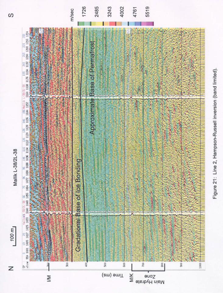
gas in the pore spaces or with hydrate lenses, since these depths and ground temperatures are within the hydrate stability zone. It is also possible that some of the discontinuous events within the permafrost section might possibly be associated with hydrate lenses. Indeed, a hole drilled by Dallimore of the GSC, a few kilometers south from this site in similar geological and temperature conditions, recovered gas hydrate samples within the permafrost section (Dallimore and Collett, 1995). Figure 21 shows the Hampson-Russell inversion results for Line 2 using the “band-limited” inversion option of the STRATA software, and a composite well log derived from L-38, 2L-38 sonic and 2L-38 VSP data. High velocities are associated with the upper portion of the perma-frost zone above the Iperk-Mackenzie Bay stratigraphic boundary. A velocity gradient boundary (300-400 ms, two-way-travel time) is associated with the base of the permafrost zone. Enhance-ment of subtle reflection events within the permafrost required the use of an aggressive amplitude scaling routine which, as a consequence, has enhanced the apparent amplitude of reflections between the base of the permafrost and the top of the known hydrate zone as evident on sonic logs. Discontinuous high-velocity lenses appear between 600 and 900+ ms. These events have slight anticlinal seismo-stratigraphic forms over the length of the section, correlative with the anticlinal form interpreted on the conventional section of Fig. 4.
RESOLUTION As an example of the difference in vertical and horizontal resolution between conventional and our high resolution sections, Fig. 22 is a travel-time blow-up of a portion of the regional N–S conventional Esso Line 85251 published by Collett et al. (1999). The events identified as those associated with the hydrate zones in the Mallik wells constitute a few low frequency legs in the apex of the anticlinal seismic stratigraphy; the lowest of these events may also represent the phase boundary between hydrate and free gas, according to Collett et al. (1999). With the observed frequency content (dominant 30 Hz), the Fresnel Zone radius governing horizontal resolution at 1 second two-way travel time is approximately 196 m. The vertical resolution is approximately 35–40 meters. Note that the shaded vertical strip on the section indicates the 1 km wide band which is effectively the width of the 1999 high resolution Line 2. In Fig. 23, showing a travel-time blow-up of the high resolution section, we correlate the hydrate occurrences as given from the well logs (Dallimore et al., 1999) with a series of discrete reflection lenses within the known hydrate zone. Here the Fresnel Zone radius is 113 m and the vertical resolution is approximately 10–15 meters. It should also be reiterated that the wells are 102 m apart, 45 degrees to the line and are between 72 and 144 m off-line from the two high resolution lines; hence correlations should be considered tenuous due to the indicated discontinuous nature of the seismic stratigraphy. However, the general variability evident in drill data is remarkably similar to that observed in the high-resolution data. This apparent correlation in character, cyclicity, and thickness between reflections on the high resolution stacked sections and hydrate layers interpreted in Mallik L-38 and 2L-38 is completely transparent at this scale on the lower resolution, conventionally


36
reprocessed seismic data displayed in Collett et al. (1999). Mapping hydrate layers at higher resolution should be extremely useful and likely essential in any future drilling research at this site, especially those involving deviated holes. In general, we believe that both the conventional and the high resolution data sets are giving similar results but at markedly different scales of resolution. From a regional perspective, the conventional data of Fig. 22 indicates three or four high amplitude events over a vertical time interval of 250 ms which may be associated with hydrate occurrences and which appear to be laterally discontinuous on the scale of 1 km or so. On a more site-specific scale, the high resolution data, with a factor of 2 increase in vertical resolution due to increased frequency content and improved Fresnel zone radii, has mapped laterally discontinuous lenses on the scale of 100 or 200 m or so. Such laterally discontinuous lenses would not be separable as discrete events on the conventional sections, with lower frequencies and larger Fresnel radii. Lateral discontinuity is aptly indicated in Fig. 17a—a correlation between a composite velocity-depth function for L-38, a synthetic, and the processed data from high resolution Line 2. In general, there is reasonable correlation between synthetics and the observed section throughout the time range. Within the permafrost zone, reflection events are relatively continuous. However, below the base of permafrost and within the hydrate stability zone, the significant events on the section do correlate reasonably well with the synthetics where the well intersects the seismic section, but are not necessarily laterally continuous over long horizontal distances.
SHEAR WAVE REFLECTION SURVEY, LINE 1 An SH survey was shot along the east-west Line 1 with similar geometry to that of the P-wave surveys discussed above (see Table 1). Figure 24 shows a 2-second shot gather of the near 96 trace data that has been spectrally balanced and F-K filtered to remove noise towards the front end of the record. This considerably enhances shallow reflection energy at near-normal inci-dence. Some quite prominent events can be seen with energy in the 10–30 Hz range in the upper half of the record along with a hint of some energy below 1 second. Love wave energy visible on the leading edge was muted prior to stacking. For reference, Fig. 25, after Sakai et al. (1999), shows the travel time-depth relationship for both P- and S-waves obtained from near offset VSP shooting in Mallik 2L-38. Figure 26 is a processed SH section using similar processing sequence to that discussed above (see Table 2). In SH mode, within the permafrost section, the wavelengths are in the 60–75 m range, as compared to average P-wavelengths in the 25–30 m range. Hence there is no improve-ment in vertical or horizontal resolving power by using shear waves within this zone. However, below the base of permafrost, the resolving power of shear wave reflectors (near 1 second two way travel time) is approximately 10 m vertically, with a Fresnel radius of 90 m, an improvement over that of the P-wave section. There are several relatively continuous events in the upper 700 ms of the section, which we postulate are associated with shallow lithology and ice-content variations. The base of ice-bearing permafrost is also the base of the more continuous reflection events. Below the base of permafrost, SH events are discontinuous, in a manner similar to that shown by the P-wave section. Since shear-wave velocities are largely unaffected by the presence of free gas in pore


38

39

40
spaces, reflection events are generated by variations in density and shear moduli through variations in lithology and/or ice (hydrate) content. In general, SH reflection events are more continuous laterally than those shown on the P-wave sections. The continuities range up to a few hundred meters or more.
INTERPRETATIONS From initial processing of our results, some basic trends are emerging: (1) with the application of high resolution surveying there is some improved spatial resolution of reflecting horizons, both laterally and vertically; (2) beneath the permafrost zone, reflection events can be associated with known velocity anom-alies; these anomalies result from the presence of significant gas hydrates in the pore space. The reflection events are laterally discontinuous over 200 m or so; hence significant lateral variations in the structure and concentration of gas hydrates lenses on the order of 200 m are inferred.
THE FUTURE This preliminary analysis of our 2-D high resolution data from the Mallik area of the Mackenzie River delta have given some interesting insights into the nature of the interpreted gas hydrates structure. On the scale of the high resolution seismic reflection experiment done at the site, it is suggested that lenses of high concentrations of gas hydrates do not appear to be uniform and continuous over the length of our seismic sections (approximately 1200 m in length) in two orthogonal directions (N-S and E-W) close by the existing wells L-38 and 2L-38. As a result, if it is necessary to properly assess the 3-dimensional distribution of such gas hydrate zones at the Mallik, or at similar arctic permafrost-dominated sites, the application of 3-D high resolution seismic techniques should be considered. Our KGS-ORNL-GSC high-resolution seismic research group is currently investigating the possibilities of 3-D applications in arctic perma-frost/gas hydrates areas.

41
REFERENCES Collett, T. S., M. W. Lee, S. R. Dallimore, and W. F. Agena 1999: Seismic- and well-log inferred gas hydrate accumulations on Richards Island, in:
Scientific results from JAPEX/JNOC/GSC Mallik 2L-38 gas hydrate research well, Mackenzie Delta, Northwest Territories, Canada, Edited by S. R. Dallimore, T. Uchida, and T. S. Collett, Geological Survey of Canada Bulletin 544, p. 357–376.
Dallimore, S. R., and T. S. Collett 1995: Intrapermafrost gas hydrates from a deep corehole in the Mackenzie Delta, Northwest
Territories, Canada; Geology, v. 23, p. 527–530. Dallimore, S. R., T. Uchida, and T. S. Collett (Editors) 1999: Scientific results from JAPEX/JNOC/GSC Mallik 2L-38 gas hydrate research well,
Mackenzie Delta, Northwest Territories, Canada Geological Survey of Canada Bulletin 544, 401 pp.
Hunter, J. A., R. D. Miller, W. E. Doll, B. J. Carr, R. A. Burns, R. L. Good, D. R. Laflen, M. Douma, and M. Riedel 1999: Feasibility of high resolution P- and S-wave seismic reflection to detect methane hydrate,
in: Technical Program Expanded Abstracts, Sixty-Ninth Annual Meeting, Society of Exploration Geophysicists, Houston, Tx., p. 445–448.
Majorowicz, J. A. and S. L. Smith 1999: Review of ground temperatures in the Mallik field area: a constraint to the methane
hydrate stability, in GSC Bulletin 544, loc.sit., p. 45–56. Sakai, A. 1999: Velocity Analysis of a vertical seismic profile (VSP) survey at JAPEX/JNOC/GSC
Mallik 2L-38 gas hydrate research well, and related problems for estimating gas hydrate concentration; in GSC Bulletin 544, loc.sit., p. 323–340.


ORNL/TM-1999/325
INTERNAL DISTRIBUTION
1. R. L. Graham 2. W. F. Harris 3. S. G. Hildebrand 4. G. K. Jacobs
5. J. M. Loar 6-8. ESD Library
EXTERNAL DISTRIBUTION
9. R. A. Burns, Geological Survey of Canada, 601 Booth Street, Ottawa,
ON K1A 0E8, CA
10. B. J. Carr, Oak Ridge National Laboratory, P.O. Box 2008, Oak Ridge, TN 37831-6038
11. E. G. Cumesty, Assistant Manager for Laboratories and Site Manager, Department of Energy, Oak Ridge National Laboratory, P.O. Box 2008, Oak Ridge, TN 37831-6269
12. M. Douma, Geological Survey of Canada, 601 Booth Street, Ottawa, ON K1A 0E8, CA
13. Jerry Elwood, Acting Director, Environmental Sciences Division, ER-74, Department of
Energy, 19901 Germantown Road, Germantown, MD 20874
14. J. P. Giesy, College of Natural Science, Department of Zoology, Michigan State University, 203 Natural Science Building, East Lansing, MI 48824-1115
15. R. L. Good, Geological Survey of Canada, 601 Booth Street, Ottawa, ON K1A 0E8, CA
16. J. A. Hunter, Geological Survey of Canada, 601 Booth Street, Ottawa,
ON K1A 0E8, CA
17. D. R. Laflen, Kansas Geological Survey, 1930 Constant Avenue, Lawrence, KS 66044
18. A. A. Lucier, National Council of the Paper Industry For Air and Stream Improvement, Inc., P.O. Box 13318, Research Triangle Park, NC 27709-3318
19. Michael C. MacCracken, Director, Office of the U.S. Global Change Research Program,
Code YS-1, 300 E Street, SW, Washington, DC 20546
20. R. D. Miller, Kansas Geological Survey, 1930 Constant Avenue, Lawrence, KS 66044
21. L. Robinson, Director, Environmental Sciences Institute, Florida A&M University, Science Research Facility, 1520 S. Bronough Street, Tallahassee, FL 32307
22. J. M. Tiedje, University Distinguished Professor and Director, Center for Microbial
Ecology, Michigan State University, 540 Plant and Soil Sciences Building, East Lansing, MI 48824


Please do not forward or discard this document.
If the document has been sent to this address in error, of if you no longer wish to receive these documents,
please return the document to W. E. Doll
Oak Ridge National Laboratory Environmental Sciences Division
P.O. Box 2008 Building 1505, MS-6038
Oak Ridge, TN 37831-6038