ù FEASIBILITY þ FOR THE OF SARNIA - North Dakota THE OF SARNIA DAM ... ln l94l E. G. Sommerfield...
48
d.\ PRELII'I NARY ENGINEERING REPORT FEASIBILITY STUDY FOR THE OF SARNIA DAM ù þ WH]T MAN soo LI NE SARNIA DA NORTH DAKOTA STATE WATER COMMISSION MAY 1979 ( T. r54 N. R.58 W. sEc. t5 N { ORY RU}I CREET swc PRoJECT 291
Transcript of ù FEASIBILITY þ FOR THE OF SARNIA - North Dakota THE OF SARNIA DAM ... ln l94l E. G. Sommerfield...

d.\PRELII'I NARY ENGINEERING REPORT
FEASIBILITY STUDYFOR THEOF SARNIA DAM
ùþ
WH]T MAN soo LI NE
SARNIA DA
NORTH DAKOTASTATE WATER COMMISSION
MAY 1979
(T. r54 N.R.58 W.sEc. t5
N
{
ORY RU}I CREET
swc PRoJECT 291

FEASIBILITY STUDY
FOR THE
REPAIR OF SARNIA DAM
Prepared BY:
'l'later Resource Englneer
Submi tted BYI
rynczyDi rector, Eng i neering Divlsîon
Approved By:
M
PREPARED FOR:
Nelson Gounty l.lHB
h
Uernon FahyState Engïneer 4
NORTH DAKOTA STATE }'ATER COMMISSIONSTATE OFFICE BUILDING9OO EAST BOULEVARDBtsilARCK, NoRTH DATOTA 58505
SllC Projecg #291
l' , it !,i , ',' , ' ' 'l: 'r.,r¡r'ri r;';, i ;l;it riti ,Ì, ;Ègl uflîl'+ î1.1¿rri',11I r,' ', ;) ii]+.¡rrri:ì r' '
'r rà '"'\i
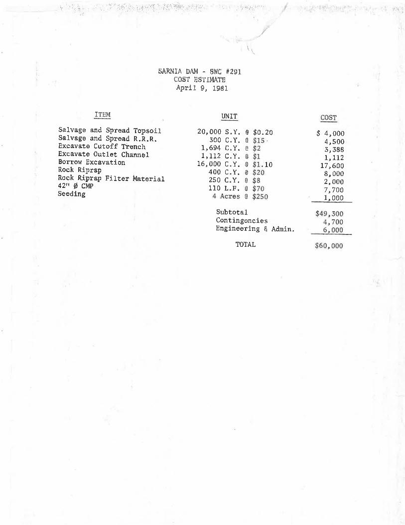
SARNTA DAM . SI'JC #29ICOËT ES'TIMATEAprit g, Iggl
TJNITÏTËM
$alvage and Spread TopsoilSalvage and Spread R.R.R.Exçavate Cutoff TrenchExcavate Outlet ChannelBorrow ExcavationRock RíprapRock Riprap Fi1ter ilfaterial42n ø CVp-Seeding
COST
20,000 s300 c
L,694 CL,LLz C
16,000 c400 c250 ClIO L
Y. G $0.20 $ 4,0004,5005,398rrL72
17,6009,0002, 0007,7001,000
$49,3004,7006,000
$6o,0oo
@
G
@
G
00G
@
YYYYYY
$1sg2$r$$$$
101.20I7AE
4 Acres $2s0
SubtotalContingenciesEngineering 6 Adnin.
TOTAL
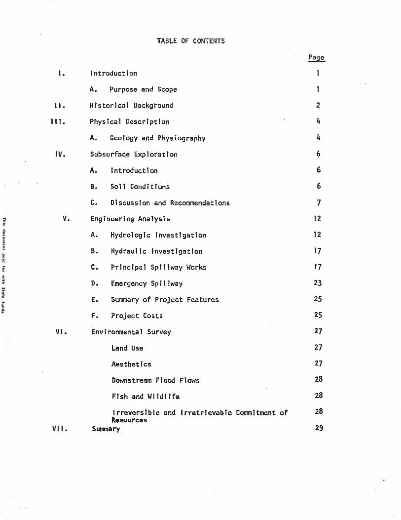
TABLE OF CONTENTS
I ntroduct I on
A. Purpose and Scope
Historical Background
Physlcal Descrlptlon
A. Geology and Physiography
Subsu rf;ace Expl orat I on
A. lntroductlon
B. Soll Conditlons
C. Discusslon and Recor¡mendât¡ons
Engineerlng Analysls
A. Hydrologic lnvestîgatlon
B. Hydraul ic lnvestlgatlon
C. Principal Spillway hlorks
D. Emergency Spillway
E. Summary of Project Features
F. Project Costs
Envlronmental Survey
Land Use
Aesthet I cs
Downstream Flood Flows
Fl sh and lli ldl I fe
lrreverslble and I rretrlevable Cornmitment ofResources
Summary
Page
I
I
2
¡r
4
6
6
6
7
l2
l2
t7
t7
23
25
25
27
27
2'l
28
28
28
29
ll.lll.
¡v.
V.
vl.
vl l.
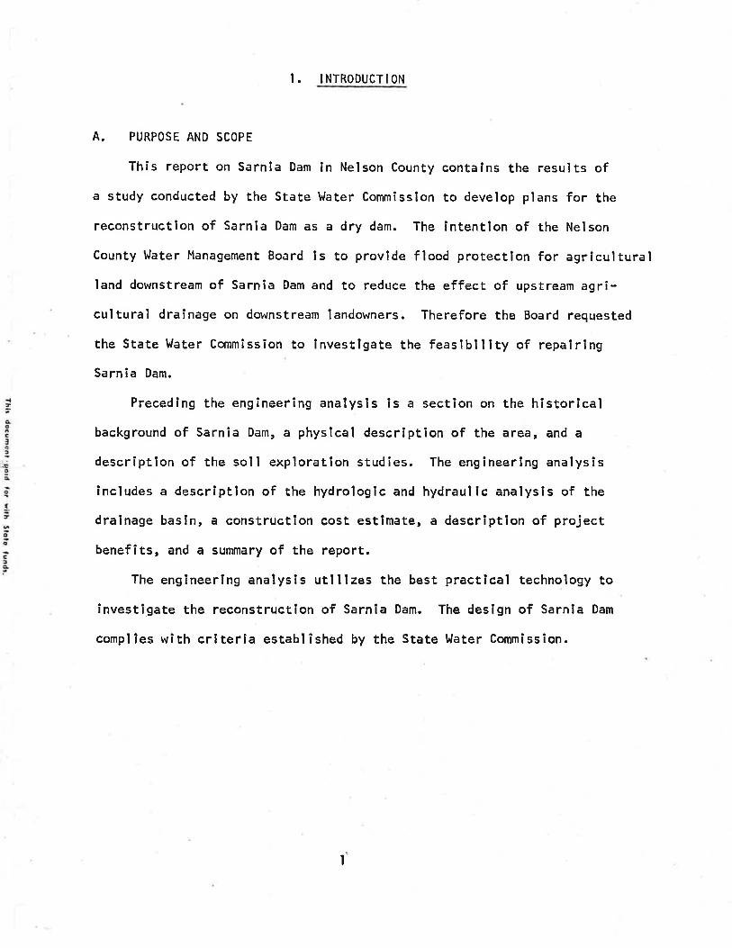
I. INTRODUCTION
A. PURPOSE AND SCOPE
This report on Sarnla Dam ln Nelson County contalns the results ofa study conducted by the State VJater Commïsslon to develop plans for the
reconstructlon of Sarnla Dam as a dry dam. The lntentlon of the Nelson
County l,Jater Management Board ls to provlde flood protection for agrlculturalland downstream of Sarnia Dam and to reduce the effect of upstream agri-cultural draínage on downstream landob/ners. Therefore the Board requested
the State l.later Commission to lnvestlgate the feaslb¡l ity of repalrîng
Sarnia Dam.
Precedlng the englneering analysls is a section on the historlcalbackground of Sarnia Dam, a physlcal descrlption of the area, and a
description of the soil exploratlon studies. The engineerlng analysîs
includes a descrlptlon of the hydrologlc and hydraul ic analysis of the
dralnage bastn, a construction cost estlmate, a descriptîon of project
benefits, and a summary of the report.The engineering analysis utlllzes the best practlcal technology to
investigate the reconstruction of Sarnia Dam. The deslgn of Sarnla Dam
compl les wîth criterla establ ished by the State ì,Jater Commission.
I
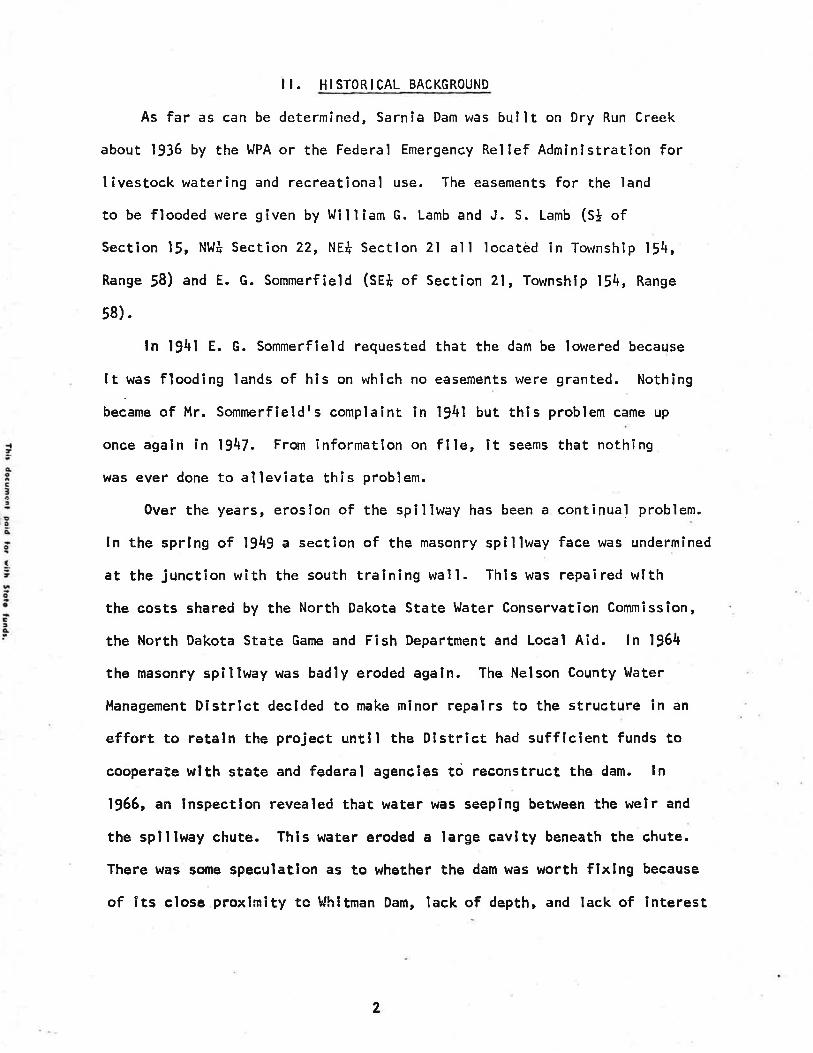
I I. HISTORICAL BACKGROUND
As far as can be determined, Sarnia Dam was bullt on Dry Run Creek
about 1936 by the llPA or the Federal Emergency Relief Adminlstration forI ivestock watering and recreatlonal use. The easements for the land
to be flooded were given by t^Jill¡am G. Lamb and J. S. Lamb (St ofSection 15, N!,lt Section 22, NEt Sectlon 2l all locatèd ìn Township l14,
Range 58) and E. G. Sommerfield (SE+ of Section 21, Townshlp 154, Range
58).
ln l94l E. G. Sommerfield requested that the dam be lowered because
Ít was floodlng lands of hls on whlch no easements were granted. Nothing
bec"r. of Mr. Sommerfieldrs complaint in l94l but thls problem came up
once agaln în 1947. Frorn informatlon on flle, It seems that nothing
vúas ever done to al leviate this problem.
0ver the years, erosíon of the spÍllway has been a continual problem.
ln the sprlng of 1949 a section of the masonry spillway face was undermined
at the Junction with the south tralning wall. Thls was repaîred with
the costs shared by the North Dakota State I'later Conservation Commisslon,
the North Dakota State Game and Fish Department and Local Aid. ln 1964
the masonry spillway was badly eroded again. The Nelson County l,later
Management District declded to make minor repairs to the structure in an
effort to retaln the project unt¡l the District had sufficient funds to
cooperate urlth state and federal agencles tó reconstruct the dam. ln1966, an inspectlon revealed that water was seepîng between the welr and
the splllway chute. This water eroded a large cavlty beneath the chute.
There þ¡as sone speculatlon as to whether the dam was worth fixing because
of its close proximlty tc Whitman Dam, lack of depth, and lack of interest
2

on the part of the Game and Fish Department. By 196B the rock and
mortar splllway had completely failed and the only portion remainlng was
the ùpstream cutoff wall. Durîng 1969 the emergency splllway was
raised 18 lnches and a reinforced concrete cutoff wall was placed across
the emergency spillway. Also a control structure was installed consistlngof a concrete drop lnlet wlth an antl-vortex devlce, a trash rack and a
36 lnch diameter corrugated metal pîpe (CHn¡. In 1974 the soll conservationservlce did some minor repalr of the emergency spîlîway. Once agaln tnthe spring of 1976, hlgh flows caused damage to the splllway, The water
Management Board then repaired the dam.
CURRENT CONDITIONS
During the 1978 spring runoff, the spillway of Sarnia Dam complerely
washed out. The Nelson County Ì^Iatet Management Board requested the
State l'later CommÎssion to check wlth the Disaster Emergency Services tosee if Sarnia Dam could be funded by the Federal Disaster Assistance
Adminîstratlon. However, the Corps of Engineers inspectors decided thatthe failure occurred from other than disaster related causes, slnce
neither the dam nor the emergency spillway was overtopped. Therefore,
dîsaster assistance funds were not made available for repair.Since that tÎme the Nelson County tlater Management Board has requ"sted
the State l,later Commîssion to proceed wlth the Investlgatlon of repairingSarnla Dam. (See Appendix C for Agreement)
It should also be noted that the recently constructed EnterpriseDrain dîscharges lnto the draînage area of sarnla Dam. Therefore, the
dam acts as a flnal control for Enterprlse Draln and should be maintained.
3
III. PHYSICAL DESCRIPTION
A. GEOLOGY AND PHYSIOGRAPHY
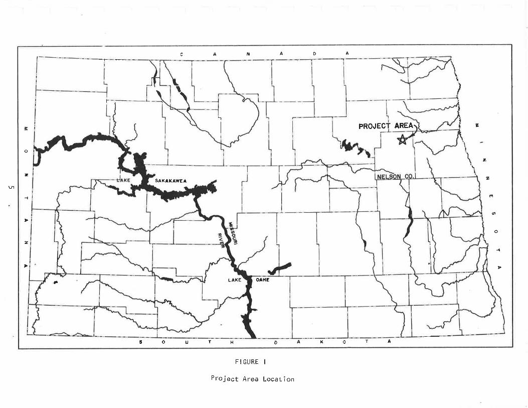
Sarnia Dam is located in the Så Sectlon l!, Townshlp 154 North,
Range 58 ttest, in the north central portion of Nelson County, ln northeastern
North Dakota (see Figure ì). The axls of the dam lles almost stra¡ghtnorth and south. The reservo¡¡ backs from the face of the dam west,
then south, and then west for approximately 2 to 3 miles.
Topographically, the dam slte occuples a närrow, moderately entrenched
channel on a gently rolllng glacìal drlft plaîn. The surflclal geology
is primarily of glacial orlgin being sltuated ln the ulestern Lake Sectîon
of the Central Lowland Province, a physlographlc province of North
Dakota. The dam site area ls part of the Drift Prairle, a reglon characterlzed
by land forms resultlng from various glacial processes.
The area around Sarnia Dam is mainly productive farmland producing
small grains and row crops. The lmmediate beneflclarles of the rebuîltSarnla Dam would be the farmers downstream from the dam. They would
receive flood protection from snowmelt ln the sprlng and from runofff rom I arge surnmer ra i ns.
Sarnia Dam is located ln the Red River Basin which ls classified as
a subhumid to humid contlnental climate wlth moderately warm summers and
cold winters. Rapid changes ln daily weather patterns are characteristic.of this area. Frequent passage of weather fronts and hlgh and low
pressure systems resuït ln a wlde varlety of weather. The annual mean
temperature is 39of wlth tha warmest month belng July and the coldest
month being January. The annual mean prec¡pltation is 17 lnches with 82
percent of the precïpitatlon occurrlng ln the months of Aprîl through
September. The aver€¡ge mean annual snowfall ls 30 lnches with 120 days
with a snow depth of I lnch or more.
4
A N A D A
-F
t-
LAXE
'1
I
PROJEC AREA 7
z
2SAKAXAWEA
tî
l,Þ
zo
-{
Þ Þ
Ô OAHE
FIGURE I
H o
o
2
\¡-l
3 o U T
Project Area Location
t( o T A

IV. SUBSURFACE EXPLORATION
A. INTRODUCTION
A subsurface exploration was inltiated by the State Water Commlssion
to determine the subsurface deposlts and the feaslb¡l¡ty of construct¡nga grassed, emergency splllway near the south abutmsnt of sarnia Dam.
The princlpal splllway plpe located near the north abutment has washed
out numerous tlmes due to high discharges durlng spring runoff.Six auger borings were drilled by Metzgerrs Prospecting service,
Mandan, North Dakota on December 28, 1978. The auger borings were
drllled with a Texoma earth drill on or about centerllne of the proposed
emergency splllway. Representative bulk samples were collected from
five of the six borings. A Water CommlssÍon engineer supervised and
reviewed the drîlling and sampling operatlons.B. S0tL CoNDtTtoNs
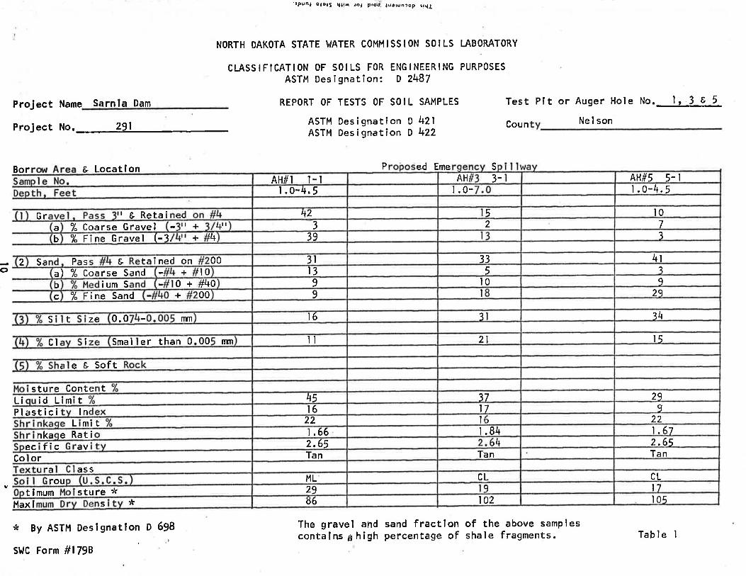
The surficial deposîts ln the proposed emergency splllway (upstream
to downstream) consist predomînantly of shaley tlll and shale-silt-claym¡xtures. The shaley till (silt-clay mixtures) was logged as ML and cL,
where as the shale-sîlt-clay mixtures were logged MH, belng composed
Predomlnantly of shale fragments of varylng sizes and proport¡ons ln a
silty matrix (See Tables I and 2).The silt-clay mixtures are moderately plastic to plastlc, slîghtly
sandy wlth a trace of gravel. Coloratlon is generally tan.to olivebrown. l'{oisture content based on vlsual examlnatlon varles from dry toslightly moÎst wlth depth. Maximum dry densltles ranged from 86 pcf forthe ML sample to 105 pcf for a CL wlth moderately plàst¡c flnes. 0ptimum
moÍsture contents were 29% and l7Z, respecttvely, for the tlvo extremes.
6

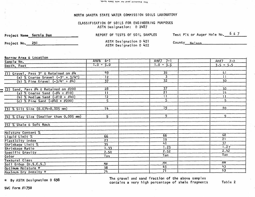
The shale-silt-clay mlxtures of the MH solr group are prastrc,occassionally sandy and contaln t to 2 lnch angular fragments of moderately
soft to moderately hard shale ln a matrlx of medium dense sllt. The
shale fragments are Iron-stalned and weathered. The shale-silt-claysamples are quite heterogeneous. They were all classlfled as CHrs thathave liquid limits of 66 and 68 and Plrs from 19 to 23. The compacred
densitles obtained on the MH samples were all less than 75 pcf. This
low density ls due to light-welght shale fragments that make up the
sand-size fractlon and also due to the sklp gradlng and poor gradationof these samples' Also the speclfic aravlty of the mlnus No. 4 fractlonis considerably lower than the ML and CL samples.
C. DISCUSSION AND RECOMMENDATIONS
It has been proposed to reconstruct a portion of the embankment
that failed in the area of the princlpal spillway p¡pe. rt ls alsoproposed to relocate the service splllway and ralse the embankment crestfive feet.
In order to rälse the embankment to the proposed deslgn elevatÍonof 1512.0 msl, additional borrow areas must be explored for embankment
construct ion.
Based on visual examinat¡on of soils encountered in the proposed
emergency splllway and subsequent laboratory tests, ure recommend the
fol lowing:
l. Perform additional borings or subsurface explorations ln the
immediate dam site area. Due to the presence of both shaley till,alluvium and slope wash (undlfferentlated) in the upstream and downstream
end of the emergency splllway respectlvely, borrow exploration should be
conflned to the higher upland surfaces, preferably the area north of the
left abutment.
7

2. Exploratory borlngs along the exlstlng centerline of the dam
lndicate the embankment was probably constructed without an lmpervlous
cutoff trench. Therefore, cleanout and excavatlon of the washed out
spillway structure should be conducted under full drawdown of the
reservoir. This should facllltate excavation of unsultable materialfrom a partial cutoff trench and further excavation of the embankment atbackslopes of 3 horlzontal to I vertical.
3. The placing and compacting of fill materlal wtthin the cutofftrench in the washed out area should be select material from proposed
borrow excavation as speclfied in paragraph I above. ln the event thatselect glaclal drift îs avallabìe from the upland surface north of the
left abutment, both Standard and Modified Proctor compact¡on testsshould be made on representatlve samples. The prlmary reason forconducting both compactlon tests is to determine the response to the
heavier compactlve efforts on the shaley drlft materlal.4. ln the event that CL glacial drlft ls available în the aforementioned
borrow area, the materîal should be placed wet of optlmum in the cutofftrench in the washed out area, and compacted tó å minimum,density of 95
percent of Standard Proctor density (ASTM D-698, Method A) or !0 percent
of Modified Procror denslty (nSf¡l D-1557, Method A).
5. The proposed relocatlon of the prlnclpal splllway plpe willcross the exlsting dam somewheres near the center of the embankment.
The consol ldatlon potential of the foundatlon deposlts is unknown.
Sînce compacted backfill wlll be required ln th¡s area, it is reconmended
that a cutoff trench be excavated through undesirable deposlts and intoflrm shale in order to obtaln a unlform foundatlon.
I

6. Glacial drift (preferably cL materiar) shourd be used as
backfill and placed wet of optímum ln the cutoff trench of the new
locatlon of the prlnclpal spillway plpe. The materlal should be cornpacted
to a mlnimum density of 95 to !8 percent of Starrdard proctor or 90
percent of Modified Proctor.
7. Materials represented by the samples submltted, may be used lnthe raising of the embankment. Although MH materlal ls not desirable inrolled-fill construction; sand clays and lean clays of the Sc and cL
soil grouP resPectlvely may be scarce or non-available in the glacialdrift deposits.
f. ilaterial excavated from the proposed emergency spillway should
be utilized in embankment consttuctlon. The emergency sptllway should
be over-excavated a minimum of l* feet along its bottom from inìet tooutlet end. Select CL glacial drift material should be used as backfill.The material should be placed at or near optlmum and at 95 percent ofstandard density. Six lnches of topsoil should be placed over the
rolled compacted fill and seeded in accordance wlth project specifications.
9
ProJ ect Name Sannia Dam
Project No.
'¡punl oao¡S ql!å /o, prgt, ¡uounrop rrr¡¡
NORTH DAKOTA STATE I^IATER COMMISSION SOILS I.ABORATORY
CLASSIFICATION OF SOILS FOR ENGINEERING PURPOSESASTM DesignatÎon: D 2487
REPORT OF TESTS OF SO I L SAMPLES
ASTM Designatìon O 421ASTM Designation D 422
Test Pít or Auger Hole No.J¿-:-!-LCoun Nel son
o
Bor
sture ConteL¡ id Lim tPlastici ln
mît
ec fic av
t Locatlon P ed Eme s
The gravel and sand fractîon of the above samplescontalns g high percentage of shale fragments.
t
L
Co orura ass
rout lmum
Hax I ** By ASTM Deslgnatlon D 698
StlC Form #1798
s E6 102 105s tu re :!c 29 9 l7
ML CL CL
Tan Tan Tan2.65 ¡4 2.65e Ratinka 1.66 r .84 1.6722 It ) 22t6 l7 9\5 37 29
a e & Soft
cl I erSma I nm00than 0 ll 2l l5
0.0zetS mÎ I6 3l i4c % Fine Sand 00+ 9 I 29b ium S 1400+ 9 l0 9
+a) % coarse Sand I t3rl0 5 ?Sa sP2 tai ned onÈ 3l00 33 4l
b % Fine Gravel (-3¡ 39t4+ I 3a % Coarse Gravel 4r rr+ 3 2 7
tçu lGr I E Retai 42 5 l0
I .0-r .0-4.5 .l.0-4.5AH,AH#t t-t 3- AHll5 5- I
Table I
Proiect Name Sarnla Dam
Proiect No. 291
'rPùnl ùaott qt!. ,o, prcd' ¡cùuñrep rl{t
NORTH DAKOTA STATE }JATER COMMISSION SO¡LS I.ABORATORY
CI.ASSIFICATION OF SOILS FOR ENGINEERING PURPOSESASTM DesÎgnatîon: D 2487
REPORT OF TESTS OF SO I L SAMPLES
ASTM Designatíon O 421ASTM Desîgnation O 422
t-Test PTt or Auger Hole No. 6 E 7
Count Na I cnn
Borrot'l Area Ele No
De th Fee
Li irt cl I ndex
rinka eLiSh n Rat o
c Grav t
lmum Den s t* By ASTH Deslgnation D 698
SIJC Form #1798
L
orCo
The gravel and sand fraction of the above samplescontalns a very hÎgh percentage of shale fragments
7t 7l 69i8mum s :t t+34:
scs HH HHMHextu essc
Tan TanTan2-qo 2 2.4721.33 1.2335 4l23 r9 2l66 66 6ö
tent
sh t RockSo
SizeI nmts 00an0 9 9 9
.000.0 r4 ì9 20
c r200+7" F ine Sand 5 5 5b tlO + #40% ¡ledium Sand (-i l2 lt lt% Coarse Sand (-ia 0+ il 2l r4
å Retai onPass I2 3 ?0
b r+% Fine Gravel 37 i0a -jtt + 3/4tt7" Coarse Gravel I l2 ll34Pas ll onG 35) 4l
5.01.0 ) 5.53.5AH#7 7-AH#6 6-l AH#l 7-2
Table 2

tqoslða
.!oqo
!.u
oo
É¡À
v ENGINEERING ANALYSIS
A. HYDROLOGIC INVESTIGATION
The TR-20 computer program developed by the U.S. Soll Conservatlon
Service was used to determine the peak dlscharge and correspondîng flowvolumes for various frequency storms. The program formulates a mathematical
model of the watershed based on the following input data: rainfalldistribution, type of soî1, soil molsture condition, land use, time ofconcentration, hydraulic characteristics of the channels and the size ofthe drainage area. The hydrologist must make accurate estimates of the
data to formulate an accurate model of the watershed. The program was
used to generate an lnflow hydrograph for Sarnla Dam to determine the
slze of the prlncipal spillway plpe and emergency splllway channel.
Explanation of the more lmportant lnput data are given ln the followingparagraphs.
Cover complex numbers (CH¡ are used în estlmattng direct runofffrom ralnfall and snowmelt. To determine cover complex numbers¡ the
soll type needs to be determined from county soil maps. There are fourmajor soil groups used for the primary classlficatlons of soils. They
are as follows:
Group A - Soils having high lnfiltrat¡on râtes even when throughlytretted, consisting chîefly of deep, welI to excesslvely drained sands
and/or gravel. These solls have a hlgh rate of water transmisslon and
would result in a low runoff potentlal.Group B - Solls havlng moderate lnfiltration rates when thoroughly
tr'retted, conslstlng chief ly of moderately deep to deep, moderately wel I
to well dralned solls with moderately coarse textures. These soils have
a moderate rate of water transmission.
l2
{tqôCl¡
.ÞIo
1I
cq
Eta
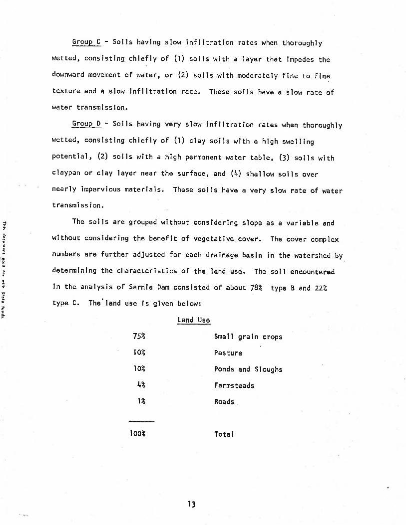
Group c - solls havlng slow lnflltratlon rates when thoroughry
wetted, consisting chlefly of (l) solls wlth a layer that lmpedes thedownward movement of water, or (2) solls wlth moderately fine to flnetexture and a slow infiltration rate. These solls have a slow rate ofwater transm¡ ssion.
GrouP D - Soils having very slow infiltratlon rates when thoroughlywetted, consìstîng chiefly of (t) clay soils wlth a high swellingpotential, (z) soils with a high permanent urater table, (l) solls withclaypan or clay layer near the surface, and (4) shallow solls overnearly impervious materlals. These soils have a very slow rate of watertransmissìon.
The solls are grouped wlthout consldering slope as a variable and
without consldering the benefit of vegetåtlve cover. The cover complex
numbers are further adjusted for each dralnage basin in the watershed by
determining the characteristics of the land use. The soll encountered
in the analysis of Sarnla Dam consîsted of about 782 type B and 2z7o
type C. The'land use ls given below:
Land Use
752 Small grain crops
¡02 Pasture
l0Z Ponds and Sloughs
\Z Farmsteads
ll Roads
r 009
t3
Total

-lzqoclt!o
o
f,oo
E¡q
The time of concentratlon (f.¡ denotes that amount of time requlredfor water to travel from the furthermost polnt of the dralnage area toits outlet. The method most commonly used by the State LJater Commission
is called the "upland Methodr¡. Thls method lnvolves separating the
different flow condltions for each drainage area and determining the
length, drop and slope of the dralnage area" Charts based on l,lannings
equatîon are used to obtain the veloclty for the various flow conditîonsusing the slope of the area. l,lhen a velocity has been obtained, the
tlme of concentratlon Is determlned by dlvldlng the length of flow reach
by the velocity. The tlme of concentratlon wlll determlne the tïme ofthe peak flow from an area.
The amount of preclpltatlon for a certaln frequency rainstorm orsnowfalI is determined by using maps avallable from the Natlonal tJeather
Service, which show the preclpitation amount In inches for North Dakota.
After the amount of precipîtatlon ls.determined for the storm frequencies
to be analyzed, the amount of precipltation Is adjusted to reflect the
amount of ponding areas within the drainage area. Generally, the more
pondlng areas in a drainage area, tha less the runoff will be. To
reflect this decrease ln runoff, the amount of precipltatlon is reduced
accordlngly.
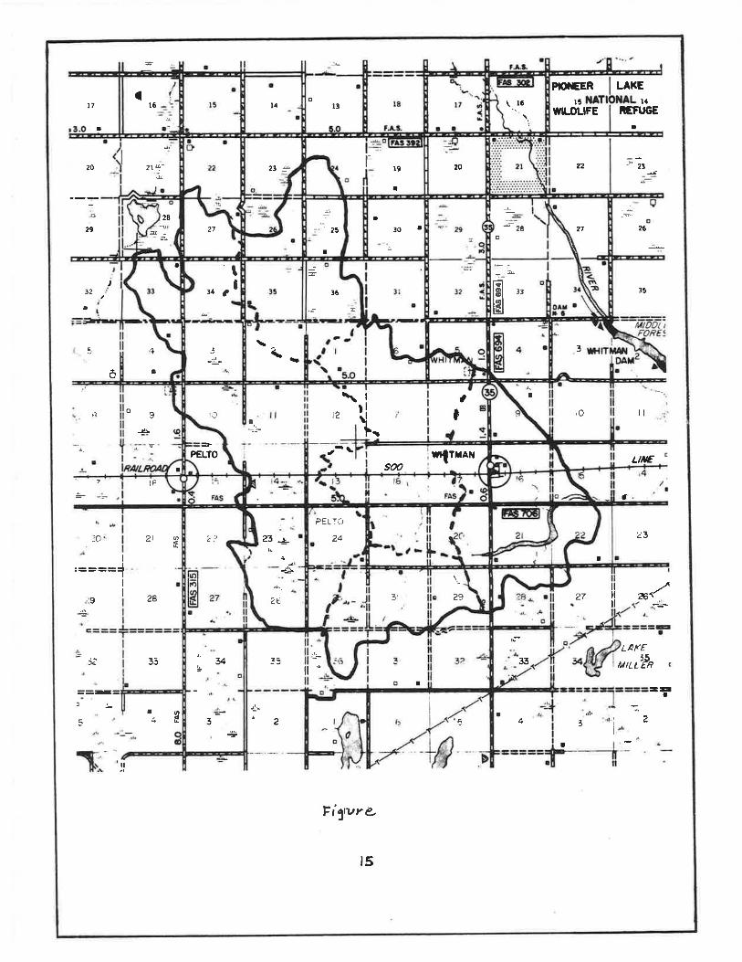
The total contributing drainage area is 26 square miles as shown on
Figure 2. The system v,ras analyzed for runoff from ralnfall as well as
from snowmelt. The rainfall is glven as the number of tnches that would
occur over a 24 hour period and thE snou¡melt ls speclfled as lnches ofrunoff that would occur over a l0 day perlod. lt was found that the
snowmelt produced the larger runoff, therefore, It was used for the
design hydrograph.
t4
-T
PIOiEER LAKE
ll l5 laWILDUFE REFUGE
t I
20 23
ñx) 26
32
a
) l5
3
ða
n og ¡O iljt
LtÆ
t€a
.to )l øf23
I=lII
9 2A 27illltl
*¿
i¿'
==ff=l:
5
LAKE35 :3 33 ntLL,PR
lr¡ =:a
I ød I4 22 5 3 1
I
t
I
Fí1vre
¡
2l
22
\t6
l----a
rõtl8l 33
lsl
-'zgo
æ
293,
ú
I30l
PEtTÖ,À
I r9
I
¡25
+
E
36
=
.J-
t3o
\-L
l¡l
23
2a
23 -rù
+5
t2I
!Ja
I
T{lrar¡soo
I
[.
\
-\=-PELTO
2?
v
3
27
t¡t1 a
¡
I
28_a
&_
(l6
1
¡
2t+-
t5

The 100 year frequency rainfal I on the watershed is approxlmated by
4"gt lnches falling în a 24 hour perlod. Ltkewlse, a snowmelt of l0oyear frequency on the watershed In approximated by 4.51 lnches of runoffthat bJould occur over a l0 day perlod.
The discharges and elevations for the various frequency storms thatsould occur ln the natural channel are shown ln Table 3. These elevationsare the elevatlons that the flood waters would reach in the naturalchannel for the respective dlscharges and frequency storms.
,êrE3t
lo9.êo
f,oa
EIê
Frequency-b"ars),
Natural Channel
Snowmal tNatural Channel
Elevat ion(HsL)
r506.4| 506. 6I 506.91507.21507.5
Elevat lon(MsL)
Frequencv(years)
5l0255o
100
t02550
100
506506507507
58I3
IlII
r6

I
Àtß3¡
,!9Âo
{,oc
E¡À
B. HYDRAULIC !NVESTIGATION
sarnla Dam is to be reconstructed as a dry dam for the purpose ofproviding flood protection for agrlcultural land downstream of the dam,
and to reduce the effects of upstream agricultural drainage on downstream
landowners. ln the design of the prlnclpal splllway, the main objectlvewas to maxlmize the reductlon of the flows out of the splllway during
the more frequent runoff such as the !, l0 and 2j year frequency. Thls
was done since generally the impact of agricultural dralnage on downstream
flows ls greatest during these lesser flows compai'ed to its impact on
the 50 year or 100 year frequency runoff. Even though the objective was
to maximize reductîon of flows on the more frequent runoff periods, the
effect on the larger runoff periods, such as the f0 year and 100 year,
was determined.
The computer program, TR-20, uras used to flood route varlous rainfalland snowmelt condÎtions through the reservolr. Alternatlve slzed prinqîpal
spïllways were compared În order to maximize flow reductlons. Appendix
A contains the summary of the various plpe size alternatlves.C. PR INC I PAL SP I LLWAY I.'ORKS
As stated above, ln slzing and deslgning the prlnclpal spillwayworksr the criteria, which had to be met, bras to provlde the greatest
percent reduction between the inflow and outflow flood waters. This
criteria hras met by using a 24 Inch dlameter CMP low level drain, a 54
inch dlameter CHP riser, and a 42 inch diamerer CHP spillway plpe. The
invert of the 24 inch diameter CMP is to be establlshed at elevation1497.0 msl. The crest of the 54 lnch dlameter CHP riser ls to be establtshed
at 1503 msl and the lnvert at the outlet of the 42 inch dlameter CMP ls
t7
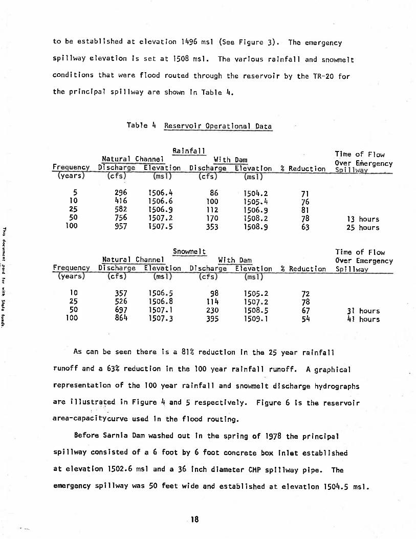
to be establ lshed at elevat¡on 1496 msl (see Figure 3). The emergency
spillway elevation ls set at 1508 msl. The varlous ralnfall and snowmelt
conditions that were flood routed through the reservolr by the TR-20 forthe principal spi I lway are shown In Table 4.
Table 4 Reservoir Operatlonal Data
Raïnfal INatural Channel !lith Dam
Time of FlowOver Eñe rgencyFr uehc
yea rs
5l02550
100
D i schac S
296416582756957
| 506. 4I 506. 6| 506. g1507.21507.5
86100ll2170353
Elevatlon Di scharc s
e Elevatlon ? Reductionm5
| 506.I 508.l 508.
l,li th Dam
4.5.
5050
7l768t7863
24929
Snowmel t
13 hours25 hours
Time of FlowOver EmergencyNatural Channel
5o5o5o50
3575266gl864
!
Âoslt
ÈIAo
{,ca
C¡À
F uenc Dischar e Elevatyea rs
t02550
100
c s msion Di scha
cfsElevatlon Z Reduction S
505.
illwa
I hoursI hours
6677
507508509
5II3
98il4230395
225I
7z78675\
34
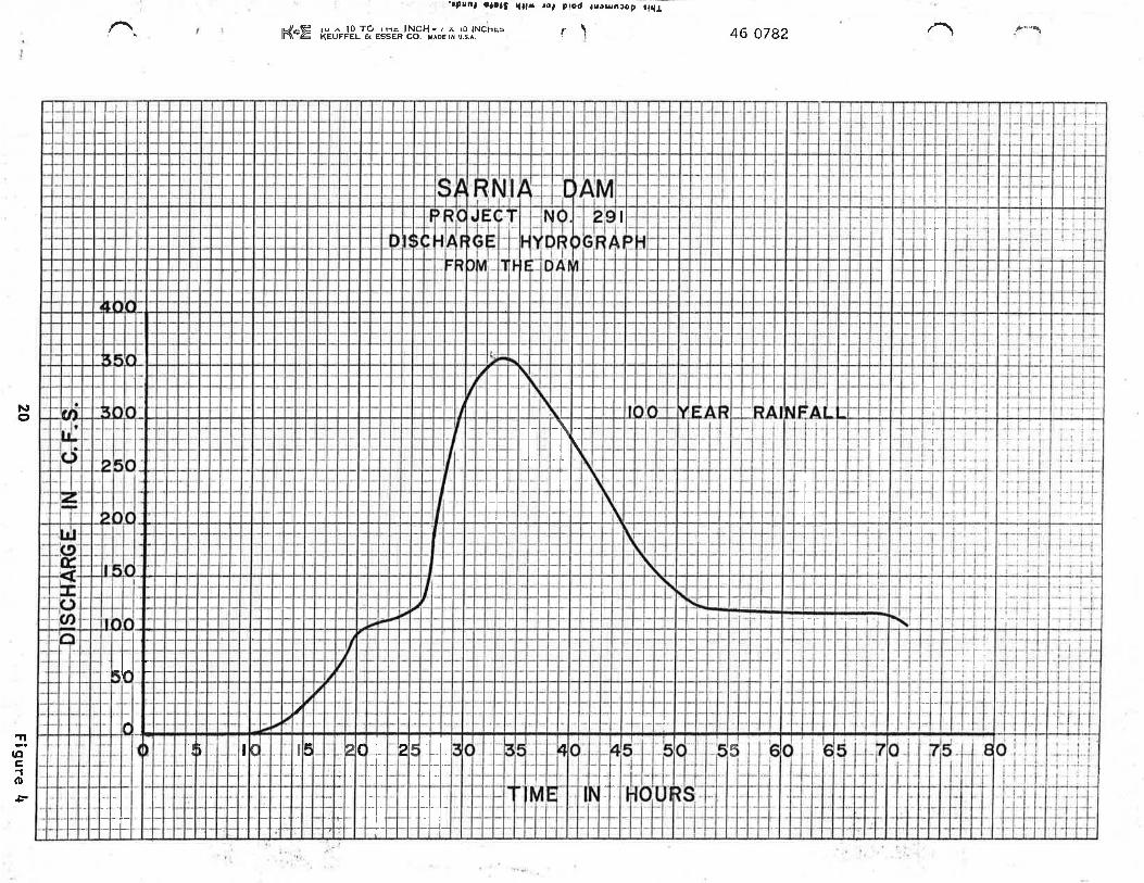
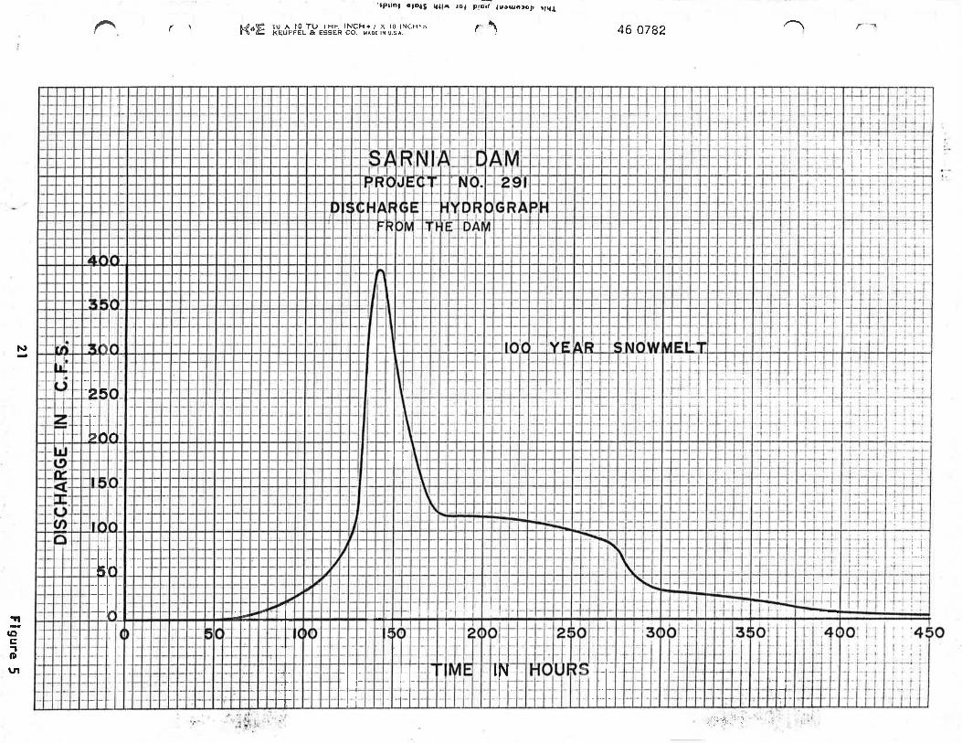
As can be seen there ls a Bl% reduction ln the zj year raÍnfallrunoff and a 63% reduction in the 100 year ralnfall runoff. A graphlcal
representation of the 100 year rainfall and snowmelt dlscharge hydrographs
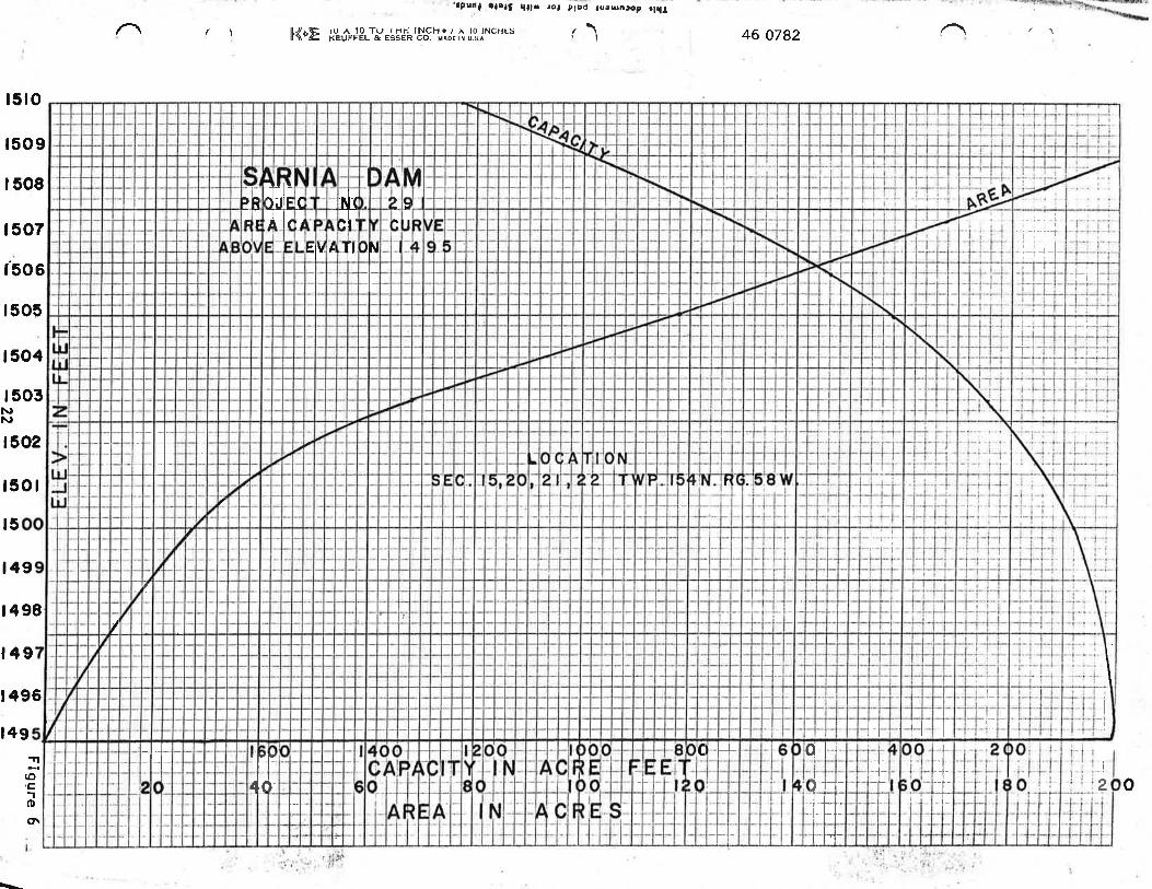
are illustrated in Figure 4 and 5 respectlvely. Figure 6 ls the reservoirarea-capacÎtysu¡ys rt.¿ ln the flood routlng,
Before Sarnia Dam washed out Ín the sprîng of 1978 the principalspillway consisted of a 6 foot by 6 foot concrete box Inlet established
at elevation 1502.6 msl and a 36 lnch diameter cMp splllway plpe. The
emergency spÎllway was 50 feet wide and established at elevation 1504.5 msl.
r8

I
t04. !l
42'' DIA. CMP SPILLWAY PIPE
eo
ANTI-VORTEX ARASH RACÍ
noîE;PI.ÂCE I-Í'CAL EERTAROUÍ{D
'Í{LET.
ELl503.OzC'olA.
ELt5lo. o3
o\
2
ROCK RIPRAP PLUNGE
al(Ocfo
TYPICAL CROSS SECTION OF
DAM AT MAIN SPILLWAYNO SCALE
II
l
-----+ili
I
I
I
I
il¡:itttl
II
,tti,ttl
III
!! l'lII
!r!ttI
II
I!Iitl
I
lt{tt
I
,lllI
itt
(Jl
(Uñlr
ir:t-r--'--T-T-
tf,
I
r¡, i I
I
l¡r,1
sI
III
I
III
Irtltltf
I
I¡
I
II
\
ILI¡
I
I
_tlrlI
I
I
I
ìr
II
I
J.J-__l.*L
l.l
I
II
!-It-
II
I
lII
II
++ --.! l
l
Iti
itli
-_f-I
/'-¡¡- i
-l-l-++
I
-rrili
I
ilrlll rl,l_i;]-
ii-llrl-r
illrL
I*r-Ï_II
---r-.J+I
Figure 420
r\((\¡c0r\o\osl
{tèocit:go{,5¡¡d. .õ
-zË -f
, õø.
È-Þ.r
(3-Eiã9ci1t)ìrEo-ØuF:O
U<5-uiYUJ
Y('
i.;,'rk:.,'
I I :1-ll,fF,+ Ë
LI
_LIñrI
at
+ ltT+ l_i il
I
II
#J,9-H-
III
-il._.II
-1- i
--Ì
-l-t--lt-
é_+Iq
-t- lll lll
c
I
1-r:ir._'
]nqtLaC'I
lr
N
'vsn ll loYW 'oJ u?ss3 Ð l3Jln¡x =z..\Jl l. .t cìrr:)Nl 0l Y / . HCNI ìH I Oa 0l Y nr >Étrx !
lh¡r do.eDsñ, poid tøt ¡llh !?olo lur¡dr.
¿8LO 9þ\i
.-
I 7i
o
-t-l +lt-,Fl l,t-l
l-9Pt-+-l-l-
-l-l t-|
+1,,).l l, llo+ t-iil rl-l r' i--
1_-lI
7
) I
ill jji
¡tI
-l
it trl,l
-1. l-r-
^l= rl r,/oI_.1_ l_ l_rIt l_i_L-I,-l- l.i'l
¡
ú,K;
'þ
IE
I
tI¿ I
,lYTT
\ooL.f,qlE
6ùt
96t I
6rl86t I
6rl9l
lo9l
zo9lNN
Êo9 I
Þo9l
eo9t
909,t
¿o9l
809 I
609t
I ' Y s n Nl loYH 'ol u:Isst ã ì3¡Jn3y 7*\\1
V srHCNl 0l Y / . r-{CNl ?H I ôl 0l Y nr 5firrfll
Thlr docuncnl paid tot rlrh ttsta frndt,
ZSLO 9Þ
orst

Referrlng to table ! it can be seen that there was a 26% reductionln the 25 year ralnfall runoff and a 2lz reductlon ln the 100 yearralnfall runoff as compared to a gl% and 63.Á reductlon In the 25 and 100year rainfall runoff respectlvely of the proposed new Sarnia Dam spillway.As can be seen from these flgures not only ís the percent reduction ofrunoff in the more frequent storms (5, 10, and 25 year) greatly lncreasedbut also the percent reductlon of runoff in the larger frequency storms(50 an¿ 100 year) has been greatly lncreased.
The outlet structure of the splllway is a rock plunge pool. Thedesign of the plunge pool is shown ln appendix B. An outlet channelapproximately 800 feet long, 15 feet wide and 2 feet deep with 4 on Iside slopes, wlll be constructed to provide adequate discharge of flocdwaters.
D. EI.TERGENCY SP ILLI^'AY
The emergency splllway would consist of a grassed waterway with a
bottom width of 85 feet and side slopes of 4 horlzontal to I vertical.The elevation of the control sectlon will be set at 1508 msl. Referrlngback to Table 4 lt can be seen that the frood waters from a 50 or a 100year frequency.snowmelt urill reach an elevat¡on of l5og.! and 1509.1msl respectlvely. Therefore there wi I I be .5 feet of v,rater f lowing inthe emergency spillway durlng the 50 year frequency snowmelt and l.lfeet of water flowing ln the emergency splllway during the 100 yearfrequency snowmelt. l,tith the elevatlon of the top of the dam set atl5l2 msl there will be 3.5 feet of freeboard durlng rhe 50 year frequencysnowmelt and 2.9 feet of freeboard durlng thè 100 year frequency snowmelt.
23

'¡P¡lnl a¡oti ql!¡ ¡o, plc.f tuou¡Ðp rl{¡
Table 5 Comparlson of Dlscharges and Reservolr Elevations betweenPrevlous Structure and Proposed Structure
Flows I'llthPrevlorrs Structure
Tlme of .FlowOver Emergency
Flows UlithProposed Structure
Fyrs.
5
l0
25
50
100
Natura
296
4t6
582
756
957
I 506.4
| 506.6
| 506.9
1507.2
1507.5
t7l285
4lz
584
755
1505.2
1505.7
1506.2
1506.7
1507.2
86
100
ll2170
353
t504.2
I 505.4
r 506. 9
1508.2
| 508.9
z
t+2
3r
26
23
2l
zReduct ion
Time of FlowOver Emergency
s nls
êV. Discha e Elev.s c a ms
tlon S lllwa
2l hrs.
27 hrs.
32 hrs.
35 hrs.
37 hrs.
D i scha e Elev.c 3 ms
5 min.
45 min.
l5 min.
20 min.
55 mln.
7l
76
8t
78
63
l3 hrs.
25 hrs.NF
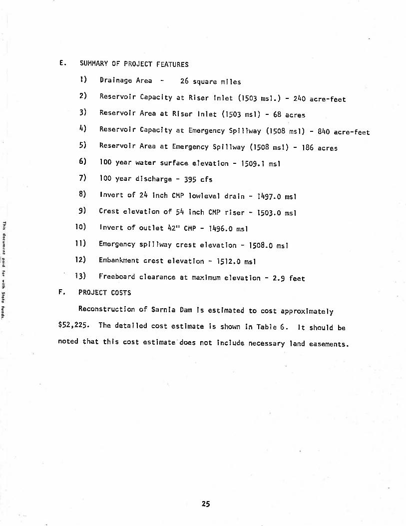
E. SUMMARY OF PROJECT FEATURES
l) Dralnage Area - 26 square mlles2, Reservoir capaclty at Riser tnlet (¡so¡ msl.) - 2t+o acre-feet3) Reservolr Area at Rlser tnlet (l5O¡ msl) - 6g acres4) Reservoîr Capacity at Emergency Splllway (1508 mst) - g4O acre-feet5j Reservoir Area at Emergency Spillway (t¡Og msl) - 186 acres6) 100 year water surface elevation - l5O9.l msl
7) l0O year discharge - 395 cfs8) lnvert of Z\ Inch CMp lowlevel draln - 1497.0 msl
9) Cresi elevatlon of 54 inch CMp riser - 1503.0 msl
l0) tnverr of ourlet t2" CMp - IU96.O msl
tl) Emergency spillway cresr elevation - l5OB.0 msl
12, Embankment crest elevatlon - 1512.0 msl
l3) Freeboard clearance at maximum elevatlon - 2.9 feetF. PROJECT COSTS
Reconstruction of Sarnia Dam ls estlmated to cost approxlmately$52,225. The detaÌled cost estlmate is shown in Table 6. tt should be
noted that this cost estimate does not include necessary land easements.
25

I tem
Salvaging s SpreadlngTop Soil
Borrow Excavatlon
Rock Riprap
Rock Rlprap FilterMaterlal
Seed i ng
Excavation of OutletChannel
54" Diameter CMPRi ser
2\t' Diameter CMPLow Level Drain
24r' l^later TightBands
42" D¡ameter CMPSpl I lway Pipe
42" l,rater TightBands
Trash Rack ¿ AntîVortex Device
Table 6
Dam Cost Estlmate
Quant I ty
18,364 sq. yd.
15,717 c.y.\12 c.y.
160 c.y:
1.8 acres
$.20lsq. yd.
$1.00/c.y.2Q.oo/c.y.
8.00/c.y.
200.00./acre
1.00/c.y.
I,200
Subtota I
Contlngencles
Unlt Prlce Cos t
; 3,673
t5,717
9,440
1,280
760
l,llllrlll c.).
7 feet 102. O0./foot
I feet 56.oo/foor
I Band 90.00/Band
105 feet 63. oo/feet
4 Bands I 83. O0/Band
7l I+
448
6,615
732
I ,200
$4t ,780
4, 178
6.267
90
I
Engineerlng, ContractAdmlnlstratlon andCons truct i onI nspect lon
26
Total s52,225
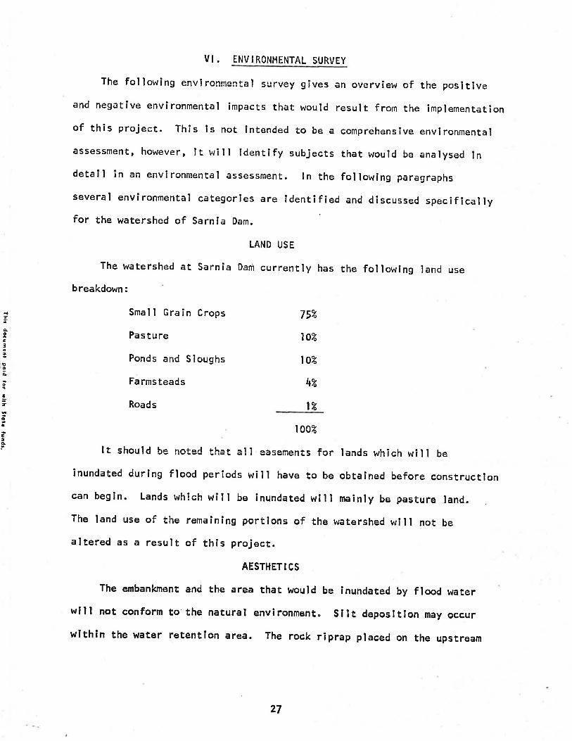
VI . ENVIRONMENTAL SURVEY
The following envlron¡nental survey gives an overview of the posltlveand negatlve environmental impacts that would result from the lmplementationof this project. This ls not lntended to be a comprehenslve envlronmentalassessment' however, lt will ldentlfy subjects that would be analysed lndetall in an environmental assessment. tn the followlng paragraphs
several environmental categorÎes are ldentified and discussed specîficallyfor the !ìratershed of Sarnla Dam.
LAND USE
The watershed at sarnla Dam currently has the fol lowing land use
breakdown:
{,ÀtC3Ð
Þ9ÈIft
oIE!C!.
Small Grain Crops
Pasture
Ponds and Sloughs
Farmsteads
Roads
752
l0zt0z
4"Á
l'Á
I 00u
It should be notad thEt all easements for lands which wÌll be
Înundated durlng flood periods will have to be obtained before constructioncan begln. Lands which will be lnundated will mainly be pasture land.The land use of the remaining portlons of the watershed wlll not be
altered as a result of thls project.
AESTHET I CS
The embankment and the area that would be inundated by flood waterwill not conform to the natural envlronment" Silt deposltlon may occurwlthin the water retentlon area. The rock riprap placed on the upstream
27
slde of the embankment wîll be exposed except durlng flood perÍods.
Also the plunge pool outlet to the prlnclpal splllway will be covered
with rock riprap. The speciflc items mentloned above will not create an
aesthetically pleaslng landscape withln the vlclnlty of the dam.
It should be noted the embankment, emergency splllway, and theborrow area wlll be seeded wlth natlve grasses
DOÌ,JNSTREAM FLOOD FLOWS
The purpose of thls project is to provide flood protectlon foragrlcultural land downstream of sarnia Dam. The proposed project wlllprovide flood protectlon from the 100 year flood.
FISH AND hIILDLIFE
The exlsting reservoir vúas not of sufficïent depth to maintaln fishllfe. Llkewlse, the proposed project, whlch is a dry dam, will notsuPport fish llfe. No field data has been obtalned on wlldllfe populatlonwithln the watershed. The proposed project wlll not change the wildlifehabItat signi f îcantly.
IRREVERSIBLE AND IRRETRIEVABLE COMMITMENT OF RESOURCES
All materlals, labor, and energy used ln the constructlon of theproJect would be lrretrievable.
28
VI I. SUHMARY.
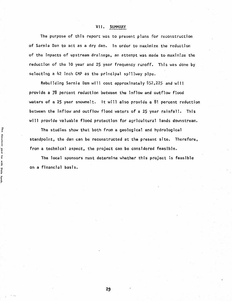
The purpose of thls report was to present plans for reconstruction
of Sarnla Dam to act as a dry dam. ln order to maximize the reductlon
of the lmpacts of upstream draÌnage, an attempt wâs made to maxlmize the
reductlon of the l0 year and 25 year frequency runoff. This was done by
selectîng a 42 lnch CMP as the principal splllway plpe.
Rebuilding Sarnìa Dam wlll cost approxîmately i52,225 and willprovide a 78 percent reductlon between the Inflow and outflow flood
wãters of a 25 year snowmelt. lt wlll also provlde a 8l percent reduction
between the inflow and outflow flood waters of a 2J year rainfall. This
will provide valuable flood protectlon for agrîcultural lands downstream.
The studies show that both from a geological and hydrological
standpolnt, the dam can be reconstructed at the present site. Therefore,
from a technlcal aspect, the project can be consldered feaslble.The local sponsors nìust determlne whether th¡s project is feaslble
on a flnanclal basls.
29

,I
lø:ÞoIo
I7
oe
e¡Â
APPEND I X A
ALTERNATE PRINCIPAL SP¡LLWAYS
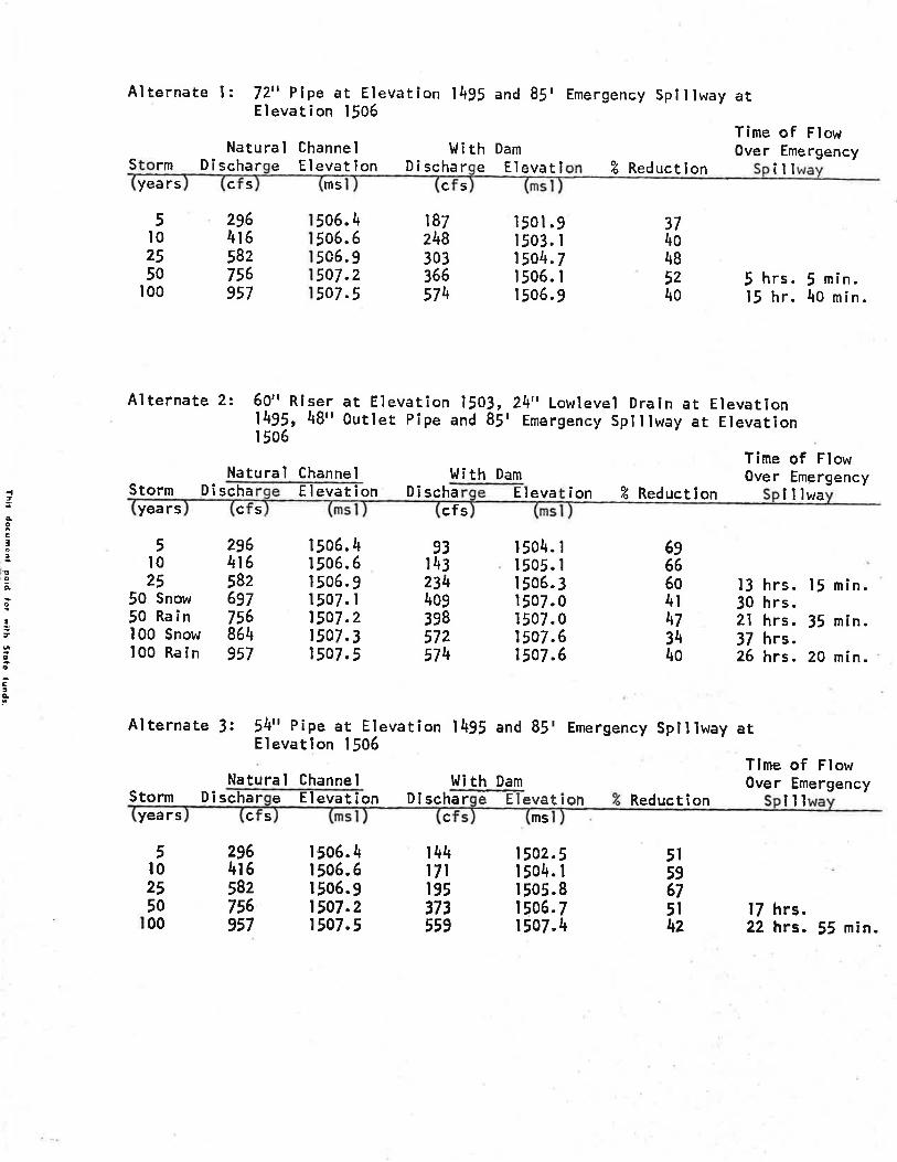
Alternate l: 72" Plpe at Elevatlon 1495 and 85tElevation 1506
Emergency Splìlway at
Natural Channel l,l i th DamTime of FlowOver Emergency
S rm Di scharyea rs c s
e Elevatlon Dischar e Elevatl Z Reduction ¡ilms c 5
5l02550
100
Alternate 2:
296416582756957
374048524o
6.\6.66.97.27.5
5o5o505o5o
1872\830336657\
r 501 .91503. r150\.7| 506. Ir 506. 9
5 hrs. I min.15 hr. 4o min.
60" Rlser at Elevation 1503, 24. Lowlevel Drain at Elevation1492, 48" Outlet Pipe and 85' Emergency Splllway ar EìevationI 506
Time of FlowNatura'l Channel I,l i th Dam Over Emergency
t
qcc¡:9so
{
oa
stèF
Storm Dischayears c s
Elevation Dischacfs
ion % Reductlon lllwa
13 hrs. 15 min.30 hrs.2l hrs, 35 min.37 hrs.26 hrs. 20 min.
Time of FìowOver Emergency
Eleva
5l025
50 Snow50 Rain100 Snow100 Rain
Alternate 3:
2964t6582697756864957
| 506.41506.6| 506. 9r507. r1507.21507.3t5o7 "5
93143234409398572574
| 504. I1505. II 506.3I 507. oI 507. 01507.61507.6
6966604t\73\4o
54" Pipe at Elevation 1495 and 85' Emergency Spillway atElevatlon 1506
Natural Channel l.li th DamStorm Di scharyeers c 5
296416582756957
e Elevation Di schar e EIevat ion Reduct î onc m5
¡il
17 hrs.22 hrs. 55 min.
5l59675l\z
5l0255000
1506.4| 506.6I 506.91507.21507.5
t44t7lr95373559
1502"5I 504. I| 505.81506.71507.\
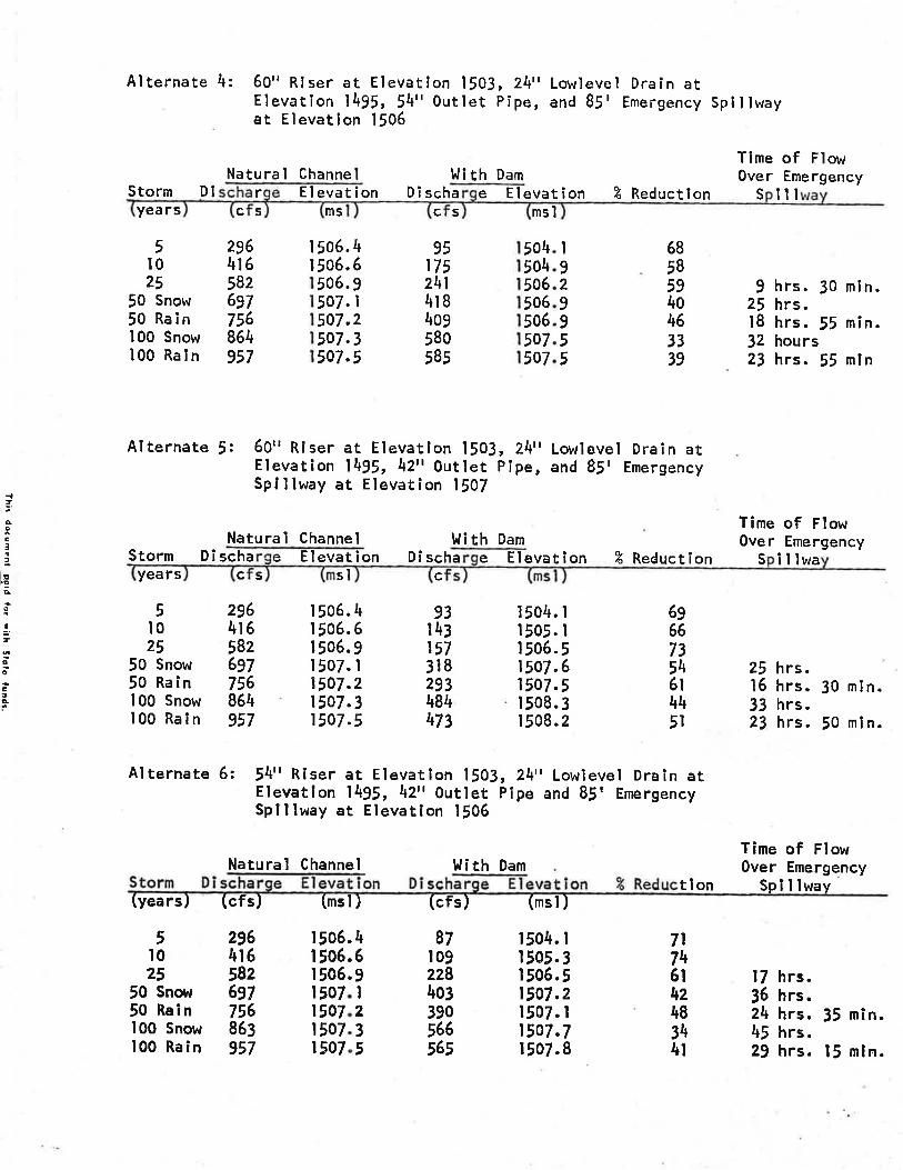
Alternate 4: 60" R¡ser at Elevatlon 1503, 24" Lowlevel Drain atElevatlon 1495, l4¡' Outlet Pipe, and 85' Emei-gency Spll lwayat Elevat¡on l506
Natural Channel Wi th DamTime of FlowOver EmergencyStorm D I
years
5t025
50 Snow50 Rain100 Snow100 Raln
rc 5
296416582697756864957
I 506.| 506.
951752\l418409580585
El evat ion Di scha Elevatïon % Reduction S illms c s msl
506.
504504506506506507507
I929o
55
469I235
7.7.7.7.
6858594o46)339
t hrs. l0 min.25 hrs.18 hrs.55 min.l2 hours23 hrs. 55 mln
Time of FlowOver Emergency
50505050
Alternate J: 60" Riser at Elevatlon 1503, 24" Lowlevel Drain atElevation 1495, 42', Outlet pipe, and 8!' EmergencySplllway at Elevation 1507
Natural Channel Wi th Dam
{!ooCltq
ts3qo
II
oo
C¡c
Storm Dî schayears c 5
e El evat ion Di scha e Elevat¡on % Reduction S illwasl c
| 506. 41506.6| 506.9I 507. I1507.21507.31507.5
93t43157318293484\73
1504. I1505. I| 506.51507.6t507.5l 508. 3I 508.2
5l025
50 Snow50 Rain100 Snow100 Rain
296416582697756864957
6g66735\6t445l
25 hrs.16 hrs. 30 min.33 hrs.23 hrs. 50 mln.
Tlme of FlowOver Emergency
Sp I I lway
Al ternate 6: 54r' R¡ser at Elevatlon 1503, 24" Lowlevel Drain atElevatlon 1495, 42'r 0utlet PÍpe and 85r EmergencySplllway at Elevatlon 1506
Natural Channel !li th Damtlon(years) (cfs) (msl ) (cfs) (msl )
r504. I| 505.3| 506.51507.21507" I1507.7t507.8
5t025
50 Snov,r50 Ral n100 Snow100 Rain
296416582697756863957
a
506506506507507507507
IIIIIIl
46II235
87t09228403390566565
7l7tt6t4z483\4t
17 hrs.36 hrs.24 hrs. 35 min.45 hrs.29 hrs. l5 mln.
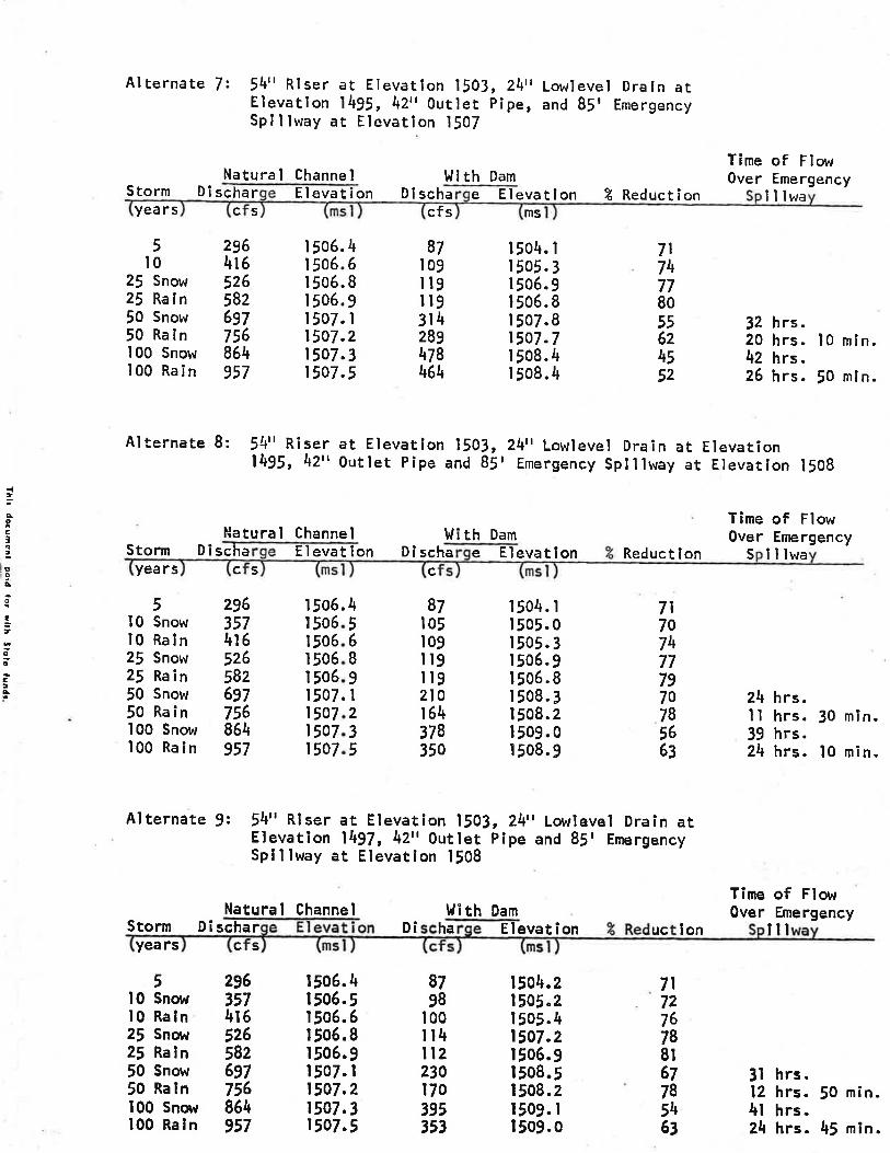
Alternate 7: 54" Riser at Elevation 1503, 24r' Lowlevel Draln atElevatlon 1495, 42,, Outlet pipe, and 85r EmergencySplllway ar Etevat¡on 1507
Natural Channel l,lith DamTime of FlowOver EmergencyStorm D î
years
5l0
2! Snow25 Raln50 Snow50 Rain100 Snow100 Rain
scha rc s
2964r65265826gl756864957
r 506. 4| 506. 6l 506. II 506.9I 507. I1507.21507.31507.5
Elevat ion Di scha e Elevatlon % Reductíoncfs ms
lllwa
32 hrs.20 hrs. l0 mln.42 hrs.26 hrs. !0 mln.
87l0gI t9ilg314289\78464
r504. Ir 505. 3I 506. 9| 506. I| 507.8t507.7I 508. 4r 508.4
7t7\7780556z\552
Alternate 8: 54" R¡ser at Elevatlon 1501495, 42', outlet pipe and
24¡' Lowlevel Drain at ElevatíonI Emergency Splllway at Elevation 15083,8S
Hatural Channel l.lî th DamTime of FlowOver Emergency
-cßcIt
ÞoIo
!_,0o
C:À
Storm Dischayea rs c s
El evat lon Dl schac
87t05t0gltgil92lo164378350
5l0 Snowl0 Raln2l Snow25 Rain50 Snow50 Rain100 Snow100 Rain
296357416526582697756864957
IIIIIIIII
7l707\77797o78566l
506506506506506507507507507
\56I9l235
e Elevatlon Reductlon S lllwa
I 504. rI 505.0r 505. 3| 506. 9| 506.8r 508. 3| 508. 2| 509. 0I 508.9
24 hrs.I I hrs. l0 min.39 hrs.24 hrs. lO min.
Alternate 9: 54¡' Rlser et Elevation 1503, Z\,t Lowlevel Drain atElevation l\97, 4Z'r Outlet pipe and 85' EmergencySplllway at Elevation 1508
Natural Channel ì,li th DamTime of FlowOver EmergencyStorm DÍschar
years c
, ,ttl0 Snot'l 357l0 Raln 4t62l Snovr 52625 Raln 58250 Snovr 69750 Rain 756100 Snow 864100 Rain 957
D¡ ha Elevation lilrlc
I 506.4| 506.5| 506.6| 506.8| 506.9r507. r1507.21507.31507.5
8798
100il4ll223017039535)
1504.21505.21505"41507.21506.91508.5| 508.21509. I| 509.0
7l7z76788t67785\63
3l hrs.12 hrs. 50 mín.4l hrs.24 hrs. 45 mtn.
slon

The orlginal sarnla Dam box Inlet and plpe that were washed out,6f x6r box lnlet at Elevatlon l 502.6, 36,' Outlet pipe wlth a 50tEmergency Spitlway at Elevation t504.5
Natural Channel I'li th DamTime of FlowOver Emergêncy
D¡ sc DÎ schas
4z3l26232t
t
.2
.7
.2
.7
.2
505505506506507
on ã Reduction I
2l hrs.27 hrs.32 hrs.35 hrs.37 hrs.
5 min,15 mîn.l5 mln.20 min.55 min,
years
5l02550
100
2964r6582756957
50650650650750v
III
l
46925
l7l285\3258'r755
IIIII
{ìÀc3tt
c.Ao
I,cø
3tÀ
{tq0EI2
!9.4
o
f7
oa
ßac
APPINDIX B
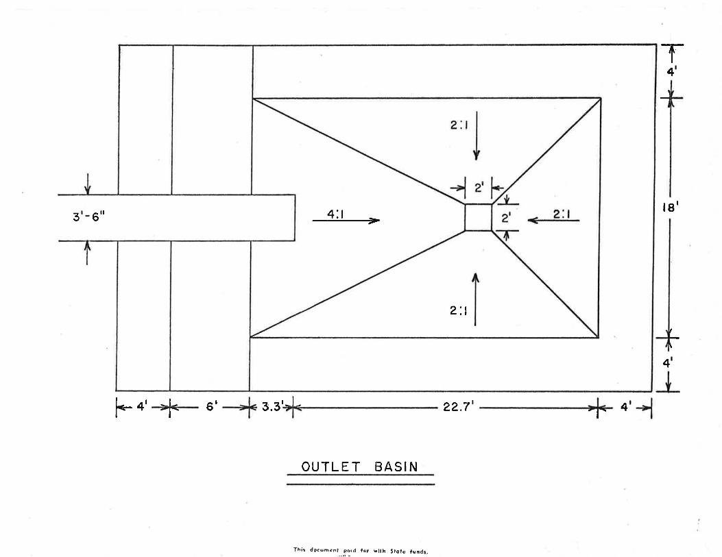
DES ! GN OF OUTLTT BAS I N
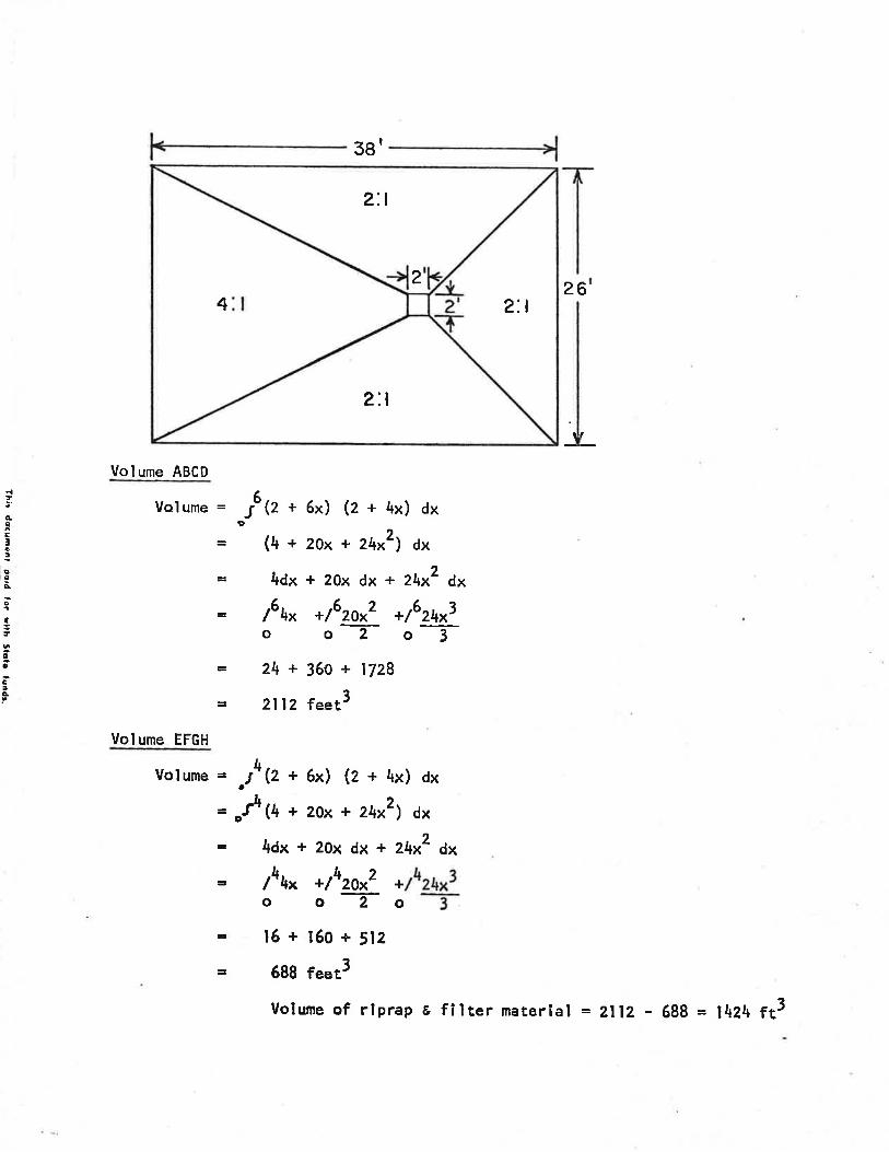
3g'
Volume ABCD
votume = J Q + 6x) (z + 4x) dx
= (4 + zox + z4x2) dx
È 4dx + 20x dx + z4x2 dx
= /6\^ +/6zox2 +/624x3o oT o- I= Z\ + 359 + tlZB
= 2ll2 feetS
Volume EFGH
.t4 {z + 6x) (z + 4x) dx
,f þ + 2ox + zhx2) dx
4dx + 20x dx + 2\x2 dx
62
It
t
ÀcEIô¡g
roõ,
o
IÌoo
Ê¡À
Volume =
lhhn */4zo*2 +o oT o
16+¡60+512688 feet3
2:t
2'.t
2
2:t
4
Volume of riprap s fl lter material = ZllZ - 688 = l4Z4 ft3

t
ÊoC¡ç!þ,9.Ào
fîoøc¡É
Volume of Filter Haterlal
Vol ume = o16 (z + 6x) (e + 4x) dx
= .16(4 + 2ox + ztx2)¿x
= /6\* */62ot- */62\^1oo2o3
= 2l 12 feet3
volurne = .J5*(z + 6x) (z + 4x) dx
= J5+ (4 + zox + z4x2) dx
¡r lï*t * */5*20*2_ +f\*foo2o3B 1655.5 feet3
volume of Filrer Materlal = zllz f¿ - 1655.5 rt3 = U56.5 ft3
Volume of Rock Riprap
voturne = of*Q + 6x) (z + 4x) dx
= or5*(4 + zox + z\xz) ¿x
ll*t* +/5tzaN?o2
+l4zgx?oTfh*
+lltz\x3'o -tr l6ss.5 feet3
uolume = o!4(z + 6x) (z + 4x) dx
= o!4([ + 2ox +zqx2) ¿x
*/rz\f-o3
o
o
E 688 feet3
Volume of'Rock Rlprap= 1655.5 fr3 - 688 ft3 = 967;5 fê
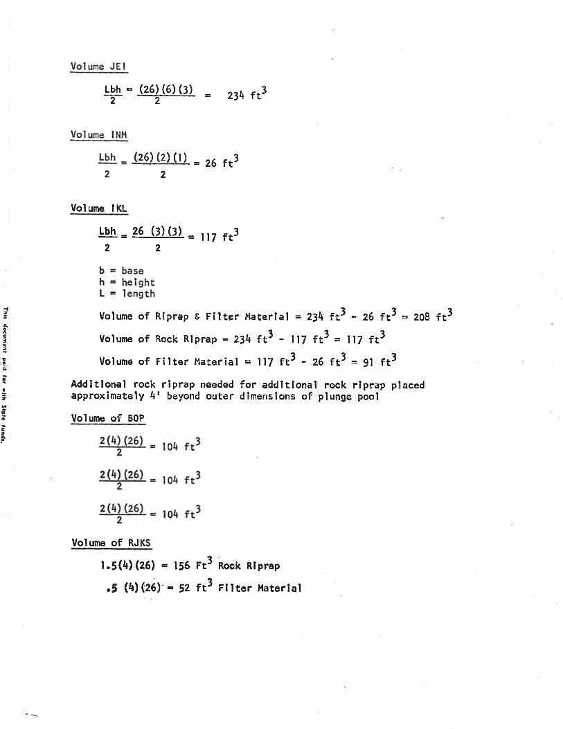
Vol urne JE I
Volumg--lNH
Lbh
-=2
Volume IKL
(26)(2)(t) = ?6 ft3
Lbh = (26) (6) (3)- = z3t+ tåTT
2
Lbh = ee (t)(¡) = lt7 ft32 2
,ècCta¡
rE:9.À
É
I,o0EtÀ
b = baseh = helghtL = length
Volume of Riprap E Filter Haterlal = 234 ft3 - z6 ¡t3 = zo8 ft3Volume of Rock Riprap = 2:.\ ft3 - ll7 ft3 = ll7 ft3Uolume of Filter ltaterial = ll7 ft3 - z6 ft3 = 9l fr3
Add¡tlonal rock riprap needed for addltlonal rock rlprap placedapproximately 4r beyond outer dïmenslons of plunge pool
Volume of BOP
Volume of RJK
1.5(4)(26) = 156 rt3 Rock Rlprrap
,5 (rt) eà'l = Sz fé Fitter ilaterial

Total Volume of Rïprap Used for Outlet Basin
g67.s ft3 + il7 fr3 + l(lo4 fr3) + 196 ft3 = ISSZ.S rt3t552' rt3 [åt4],= s7.5 yd3
Total Volume of Fi for Outlet Basln
\l¡6.s ft3 * 9l ft3 + sz fê = s99.5 rJ599.s rt3 t-r:¿ll = zz.2 ,¡dj(zl tt3l
t
6oË33
,EôL:It
coÉå?.
.f=.
I1
4
lg'
4
3 ^ilb
Ili
þ+| -l 6' 3.3rl- 22.7' 4-l- -l-
OUTLET BASIN
2:t
4:t >
Yhir docuFani got¿ lor yllh Stolo lundl,

r Irlr6se
A - --B.a/.' I.l
F{-I
D
Jo
g
OUTLET BASI N
{fèoa¡ê
9:
o
!.t
oog5
APPENDIX C
AGREEMENT
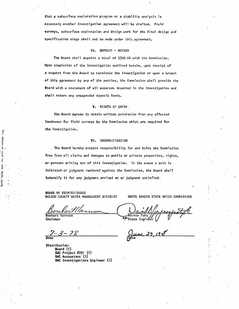
SARN IA DAHSvC Projecc /291June 29, 1978
ê9!E.ETET.].Prel imlnary lnvestlgatlon
by rheNorth Dakota State l,/ater Conmtsslon
I. PARTIES
THls AGREEMENT is between the North DakoÈa state l.rðter conmission,hereinafter referred to as the conmission acti.ng through the stateEnglneer, vern Fahy and the Board of commissioners, Nelson county l.laterl{anagement District, hereinafter referred to as the Board, actíng thro.ugh
Its Chairman, Benhait Varnson.
ll" PRoJECT, LoCATION AND PURPOSE
The Eoard has requested the commission to lnvestigate and determinethe feasibílity of repairi.ng the dam and modifying it to act as a drydam for flood control purposes. said dam is located ïn section 15¡
Tovlnship lJ4 North, Ra.nge !8 lJest, in Nelson county. The reservo!r has
a minimum amount of recreational value, but is important for the retent¡onof flood r¡raters. The purpose of this investigation ¡s to determîne thefeasibility of the project as described hereÌn.
I I I. PRELI¡{INARY INVESTIGATION
The parties €gree that further information is necessary concernîng
the proposed project. Therefore, the commission shall conduct a preliminarylnvestigation consisting of the fol lot"ring:
' l- The acquÎrí¡s of field survey data necessary for the investigation.2. A hydrologic analysis of the watershed.
3. A prelimínary design of the hydraulic and structural features ofproposed improvements.
[. A detatled cost estimate of the proposed project.
5. A detalled preliminary engineering report.. The lnvestigation outl¡ned herein does not include a subsurface
exploratlon pr.ogram or a stability analysis. lf the co¡¡mission determines
a:.
- t ¡{
íil,
,qoc:tI
3Ào
1,co
C¡q
{lÀ0c3
'!a
{,o
.oIa I
that a subsurface exploratlon progrðm or a stabillty analysls lsnecessary another lnvestlgatlon êgreement wlll be drafted. Field
surveys, subsurface exploration and design þ.,ork for the final des.lgn and
specffication stage shall not be made under this agreement.
IV. DEPOSIT - REFUNO
The Board shall depoist a total of 5500.00 wíth the Commission.
Upon completlon of the investigation outlined herein, upon receipt ofa request from the Board to terminate the lnvestigation or upon a breach
of this êgreement by any of the part¡es, the Cosrnisslon shall provide the
Board with a statement of all expenses incurred in the investigation and
shall return any unexpended deposit funds.
V. RIGHTS OF ENTRY
The Board ãgrees to obtain wr¡tten permission from any affected
landov¡ner for field surveys by the Comnission which are requÍred forthe investígation.
. YI. INDEI.,INIFICATION
. The Board hereby accepts.responsibility for and holds the Conrnission
free from all claîrns and damages to publÍc or private properties, r.ights,
or persons arising out of thÍs investigation. ln the event a suit is
lnltiated or ju.dgment rendered.aga¡nst the Corunission, the Board shalllndemnify it for any judgment arrived at or judgment sðt¡sf¡ed.
BOARD OF COMHISSIONERSIIELSON COUNTY T.JATER }4ANAGEHENT DISTR¡CT NORTH DAKOTA STATE I.'ATER CO}4}4ISSION
a
rGhal rman
7-s- zFDate
Dl strlbutlon:Board (l)StlC ProJect #291 (l)SllC Accountant (l)St{C lnvestigations Engineer (l}
te Eng i
Q'Lrú- Jq tîí(y,"