Feasibility Analysis of Spacecraft Design for a Manned ...
14
44th International Conference on Environmental Systems ICES-2014-41 13-17 July 2014, Tucson, Arizona Feasibility Analysis of Spacecraft Design for a Manned Mars Free-Return Mission in 2018 Hiroyuki Miyajima 1 Tokyo Jogakkan College 1, Machida, Tokyo, 194-0004, Japan and David Klaus 2 University of Colorado Boulder 2, Boulder, Colorado, 80309 The Inspiration Mars Foundation (IMF) is committed to sending a two-person American crew, a man and a woman, on a journey to fly around Mars and then return to Earth safely. In 2018, Earth and Mars will share a unique orbit, creating an opportunity to travel to Mars and back in only 501 days. In this paper, we conducted the design of a mission and spacecraft for the Inspiration Mars (IM) mission using the design procedures described in the Human Spaceflight textbook and then evaluated them based on the rules of the Mars Society International Student Design Competition. We especially focused on the habitable volume which is an important system driver for designing spacecraft. The Initial Mass in Low Earth Orbit (IMLEO) for this mission was estimated using heuristics and relationships derived from the rocket equation while varying the habitable volume per crewmember from 6 m 3 to 18 m 3 (24 m 3 to 72 m 3 total pressurized volume). As a new spacecraft design, a Crew Reentry Vehicle (CRV) and a Mars Transit Habitat (MTH) with 72 m 3 pressurized volume and hybrid Life Support System (LSS) remained by comparing the Life Cycle Cost (LCC)s and failure rates. The crew and the cargo can be launched by three Falcon Heavy launches. Nomenclature 4BMS = Four Bed Molecular Sieve AMCM = Advanced Mission Cost Model B = Hardware generation (1 for new design, 2 for second generation) CER = Cost Estimating Relationship CM = Crewmember CRV = Crew Reentry Vehicle CS = Crew supply D = Difficulty (0 for average, 2.5 for very difficult, -2.5 for very easy) DPC = Development and Production Cost DRM = Design Reference Mission ECLSS = Environmental Control and Life Support System ESMD = Exploration Systems Mission Directorate f i = Failure rate of subsystem i HTV = H-II Transfer Vehicle i = Number of subsystem IM = Inspiration Mars IMF = Inspiration Mars Foundation IMLEO = Initial Mass in Low Earth Orbit IOC = Initial Operation Capability ISS = International Space Station I sp = Specific impulse 1 Professor, Faculty of Liberal Arts for Global Studies and Leadership. 2 Associate Professor, Aerospace Engineering Sciences.
Transcript of Feasibility Analysis of Spacecraft Design for a Manned ...

44th International Conference on Environmental Systems ICES-2014-41 13-17 July 2014, Tucson, Arizona
Feasibility Analysis of Spacecraft Design for a Manned Mars Free-Return Mission in 2018
Hiroyuki Miyajima1 Tokyo Jogakkan College 1, Machida, Tokyo, 194-0004, Japan
and
David Klaus2 University of Colorado Boulder 2, Boulder, Colorado, 80309
The Inspiration Mars Foundation (IMF) is committed to sending a two-person American crew, a man and a woman, on a journey to fly around Mars and then return to Earth safely. In 2018, Earth and Mars will share a unique orbit, creating an opportunity to travel to Mars and back in only 501 days. In this paper, we conducted the design of a mission and spacecraft for the Inspiration Mars (IM) mission using the design procedures described in the Human Spaceflight textbook and then evaluated them based on the rules of the Mars Society International Student Design Competition. We especially focused on the habitable volume which is an important system driver for designing spacecraft. The Initial Mass in Low Earth Orbit (IMLEO) for this mission was estimated using heuristics and relationships derived from the rocket equation while varying the habitable volume per crewmember from 6 m3 to 18 m3 (24 m3 to 72 m3 total pressurized volume). As a new spacecraft design, a Crew Reentry Vehicle (CRV) and a Mars Transit Habitat (MTH) with 72 m3 pressurized volume and hybrid Life Support System (LSS) remained by comparing the Life Cycle Cost (LCC)s and failure rates. The crew and the cargo can be launched by three Falcon Heavy launches.
Nomenclature 4BMS = Four Bed Molecular Sieve AMCM = Advanced Mission Cost Model B = Hardware generation (1 for new design, 2 for second generation) CER = Cost Estimating Relationship CM = Crewmember CRV = Crew Reentry Vehicle CS = Crew supply D = Difficulty (0 for average, 2.5 for very difficult, -2.5 for very easy) DPC = Development and Production Cost DRM = Design Reference Mission ECLSS = Environmental Control and Life Support System ESMD = Exploration Systems Mission Directorate fi = Failure rate of subsystem i HTV = H-II Transfer Vehicle i = Number of subsystem IM = Inspiration Mars IMF = Inspiration Mars Foundation IMLEO = Initial Mass in Low Earth Orbit IOC = Initial Operation Capability ISS = International Space Station Isp = Specific impulse 1 Professor, Faculty of Liberal Arts for Global Studies and Leadership. 2 Associate Professor, Aerospace Engineering Sciences.

International Conference on Environmental Systems
2
LCC = Life Cycle Cost LSS = Life Support System LiOH = Lithium hydroxide M = System dry mass mbo = Burn-out mass MDRS = Mars Desert Research Station MF = Multifiltration MOCM = Mission Operations Cost Model mprop = Propellant mass MTH = Mars Transit Habitat N = Maximum number of subsystem NASA = National Aeronautics and Space Administration NEA = Near Earth Asteroid OGA = Oxygen Generation Assembly Q = Total quantity of development and production R = Number of redundancy of subsystem S = Type of mission (2.13 for human habitat, 2.27 for human reentry) SLS = Space Launch System SPWE = Solid Polymer Water Electrolysis STEM = Science, Technology, Engineering and Math TCCS = Trace Contaminant Control Systems TMI = Trans-Mars Injection VCD = Vapor Compression Distillation ∆v = Velocity increment
I. Introduction A private organization called the Inspiration Mars Foundation (IMF) announced on February 27, 2013 that it is
planning a manned Mars flyby called the Inspiration Mars (IM) mission1. The IMF is committed to sending a two-person American crew, a man and a woman, on a journey to fly around Mars at a distance of 160 km and then safely return to Earth. In 2018, the planets will literally align, offering a unique orbit opportunity to travel to Mars and back in only 501 days. The mission will provide a platform for unprecedented science, engineering, and educational opportunities, using state-of-the-art technologies derived from NASA and the International Space Station (ISS).
A feasibility analysis has been published by the IMF2, 3. In addition, the Mars Society is holding an international student design competition for the IM mission4. Designs in the competition will be evaluated using a scoring system made up of a 100 points maximum score broken down into 30 points for cost, 30 points for technical quality of design, 20 points for operational simplicity and 20 points for schedule.
As of January 2014, 38 teams representing 56 universities in 15 countries had registered for the student competition5. This competition will inspire and motivate youth through the promotion of the science, technology, engineering and math (STEM) educational program. For example, in the Space Habitat Design course taught at the University of Colorado Boulder, in the fall semester of 2013, the contest was used to motivate the students who conducted group work to design new mission concepts and architecture. They used Human Spaceflight: Mission Analysis and Design6 as a reference.
Various studies have been published on manned Mars missions, such as NASA Case Studies, 90-Day Study, Synthesis Group, NASA Mars Design Reference Mission (DRM) version 1.0 - 5.0, Exploration Systems Mission Directorate (ESMD), and Mars Direct7. In such studies, the plans included landing and conducting activity on the Martian surface with large-scale exploration systems. Compared to those missions, the unique characteristics of the IM mission are that a crew leaves Earth, flies by Mars, and returns to Earth using a fast free-return trajectory of 501 days without needing any additional maneuvers after the Trans-Mars Injection (TMI). Since the crew will not land on Mars, the system and operations are relatively simple. As the first of its kind, the mission’s challenge is to achieve this human deep space flight with current existing technology. However, the crew cannot easily abort the mission after the spacecraft leaves Earth since it is on a free return trajectory. In addition, the crew cannot use resources such as carbon dioxide available on Mars since they will not land. Therefore, the Environmental Control and Life Support System (ECLSS) for this mission must be ultra-reliable, and able to operate reliably for over 500 days.

International Conference on Environmental Systems
3
The whole system needs to be developed and launched by the end of 2017 to complete this mission. Therefore, the limited time between now and 2017 presented a crucial factor to consider in designing the mission. In this paper, we conducted the design of the mission and spacecraft for the IM mission using the design procedures described in the Human Spaceflight textbook and then evaluated them based on the rules of the Mars Society International Student Design Competition.
II. Mission goals and requirements
A. Mission statement As stated in the IM mission statement, this project aims to execute a human flyby mission to Mars in late 2017.
The IMF is committed to sending a two-person American crew, a man and a woman, on a journey to fly around Mars at a distance of 160 km and then safely return to Earth1. Eight goals and four requirements for the mission are described in the technical summary report published by the IMF3. Regarding the mission design specifically, three goals and three requirements are studied here. The three goals are to 1) demonstrate the feasibility of human missions to Mars, 2) address the technical risks involved with human deep space exploration, and 3) conduct research on human physiology during deep space travel. The three requirements are to 1) implement the earliest practical IM fast free-return trajectory, 2) use two crewmembers consisting of one man and one woman, and 3) return the crew safely back to Earth.
B. Mission requirements and constraints The mission requirements and constraints governing the spacecraft design derived from these three goals and
three requirements are shown in Table 1. The functional requirements consist of a two-person crew size made up of a man and a woman, a mission duration of at least 501 days, a destination to reach Mars at a distance of 160 km, the operating environment is at zero-g with deep space extreme temperature and radiation, a trajectory with a fast return trajectory, and vehicle needs for reentry and transfer.
Table 1. Top level mission requirements and constraints Factors Mission requirements and constraints
Functional requirements Performance :
Crew size Mission duration Destination Operating environment Trajectories Vehicle
2-person – a man and a woman At least 501 days Fly around Mars at a distance of 160 km Zero-g in deep space, extreme deep space temperatures and radiation Fast free return trajectory Crew Reentry Vehicle (CRV) and Mars Transit Habitat (MTH)
Operational requirements Duration:
Vehicles ECLSS Habitable volume
Logistics: Mission operations: Command, Control, and Communications:
At least 501 days Storage or recycling More than 6 m3/CM and less than 18 m3/CM
Limited to current inventory of launch assets Minimize complexity and cost Communications delay between Mars and Earth
Constraints Cost Schedule Development
Minimize Must launch at launch window between Dec. 24, 2017 and Jan. 4, 2018 Current existing vehicle, technology, and operation
The operational requirements consist of Crew Reentry Vehicle (CRV) and Mars Transit Habitat (MTH) that are
operational for at least 501 days, an ECLSS that includes both storage and recycling options, an optimal habitable volume requirement between 6 m3 /Crewmember (CM) and 18 m3 / CM, logistics limited to the current inventory of launch assets, the mission operation needs of minimum complexity and cost, and a communication system with a delay between Earth and Mars. The constraints of cost and the 2017 launch window restrict development to currently existing vehicles, technology, and operations.

International Conference on Environmental Systems
4
C. Top-level mission concept The IM mission concept has been exhibited by the IMF1-3. The sequence includes a two person crew consisting
of a man and a woman, vehicles, and a launch system carrying the crew and the logistics for 501 days for flying to Mars by the TMI, doing a flyby around Mars, and returning to Earth using a fast free-return trajectory. This mission architecture consists of crew, trajectory, space vehicle, launch system, and mission operation elements.
D. Trajectory and launch window This mission utilizes what is known as a “fast free-return trajectory”2. This particular trajectory, shown in Fig. 1,
occurs only once every 15 years with the next opportunity arising in late 2017. The total travel time is 501 days. There is a fixed and finite time window in which to execute the TMI burn for the IM mission trajectory. Due to
rocket use restrictions for the good of completing the mission, the TMI window opens when the C3 (minimum energy requirement to accomplish the mission for a given payload mass) drops below 40.5 km2/s2. Due to the limitations of the current heat shield materials, the window closes when the expected Earth reentry speed at the end of the mission exceeds 14.2 km/s. This results in a TMI window from December 24, 2017 to January 4, 20182.
Figure 1. Inspiration Mars Trajectory
III. Mission architecture
A. Mission elements and trade tree A space mission architecture is the mission concept plus a definition of each of the elements of the mission8.
Four of the mission elements, consisting of the mission concept, development strategy for CRV, habitable volume, and selection of the ECLSS type, have been chosen from the requirements and constraints in Table 1 as important mission architecture elements for making trade trees to assist with designing this mission architecture. There are two options for the mission concept consisting of multiple and single launch methods, two options for the development strategy for CRV, two options for the MTH habitable volume consisting of 6 m3/ CM and 18 m3/CM, and 3 options for selection of the ECLSS type consisting of a storage, recycling, or hybrid (storage and recycling) type.
The trade tree made up by a combination of the four mission elements is shown in Table 2. Table 3 shows possible space launch system candidates for 2017. Trade tree options 7-12 in Table 2, which are a combination of multiple launch and commercial based development, such as Dragon, are studied in this section because there is no existing rocket with an ability to launch a 130-ton payload in a single launch. The SLS Block I rocket development will not be ready in time for the launch in 2017, and CRV based on Orion is too large for 2 crewmembers. The launch costs of Falcon 9 for crew and Falcon Heavy for cargo are the lowest in Table 3.

International Conference on Environmental Systems
5
Table 2. Trade tree for designing mission architecture
Mission concept
Development strategy for
CRV
Habitable volume, m3/CM
ECLSS Type
Launch for crew
Launch for cargo
Option number
Multiple Launch
Orion (Government)
18 Storage
Delta IV Heavy SLS Block I
1 Recycling 2 Hybrid 3
6 Storage 4 Recycling 5 Hybrid 6
Dragon (Commercial)
18 Storage
Falcon 9 or
Falcon Heavy Falcon Heavy
7 Recycling 8 Hybrid 9
6 Storage 10 Recycling 11 Hybrid 12
Single Launch
Orion (Government)
18 Storage
SLS Block II -
13 Recycling 14 Hybrid 15
6 Storage 16 Recycling 17 Hybrid 18
Dragon (Commercial)
18 Storage 19 Recycling 20 Hybrid 21
6 Storage 22 Recycling 23 Hybrid 24
Table 3. Comparison of space launch systems
Falcon 9 9 Falcon Heavy 10 SLS Block I 11 SLS Block II 11
Delta IV Heavy 12
Payload to LEO, kg 13,150 53,000 77,000 143,000
23,000
Payload to TMI, kg TBD 13,200 20,200 TBD
TBD
Launch Cost, M$ 56.5 77.1 500 140
Fairing Diameter, m 5.2 5.2 TBD 8.4
5.0
First operation, year 2010 2014 2017 TBD
2004
B. Habitable volume and spacecraft mass Vehicle mass
The initial vehicle mass is estimated based on the pressurized volume required by the crew. The pressurized volume per crewmember as a function of the mission duration and performance level required by the crew has been defined13 and will be discussed in a later section of this paper. The first calculation regarding the spacecraft mass can be estimated using the following equation, which is based on historical data for human spacecraft14. This value represents the expected mass at the end of the maneuver, which is called the burn-out mass, or mbo.
mbo = 592 x (number of crew x mission duration [day] x pressurized volume [m3])0.346
For example, if the pressurized volume per crewmember is assigned as 36 m3, the mbo is as follows: mbo = 592 x( 2 x 501 x 36)0.346 = 22,341 kg The spacecraft mass is estimated at 18,146 kg by subtracting the reduced mass of 4,195 kg, (19 % of the burn-out mass mbo)
15, from 22,341 kg. Propellant mass
The most massive component of the spacecraft is the propellant, which depends on the vehicle mass, the propulsion system efficiency, and the size of the propulsive maneuvers, represented by a velocity increment. The propellant mass, mprop, is described using the vehicle mass following the maneuver, mbo, the required velocity

International Conference on Environmental Systems
6
increment, ∆v, and the propulsion system’s specific impulse, Isp. Here, the values have been plugged into the form for a rocket equation:
mprop = mbo (e
(∆v/Isp・
g) - 1) where g is the acceleration due to gravity, 9.8 m/s2. The ∆v and Isp were estimated 2 as the ∆v being 4882 m/s, and the Isp being 340 s when the two values are assigned, the mpop is 60,393 kg as follows. mprop = 18,146 (e(4,882/340
・
9.8) - 1) = 60,393kg Applying the 15 % rule-of-thumb15 yields a mass of 9,059 kg for the propulsion system. Adding this 9,059 kg, consumable mass of 8,812, and crew of 220 kg to the original mbo estimate of 18,146 kg gives a total of 36,237 kg. When the above equation is repeated, the new total mass is estimated to be 120,603kg. mprop = 36,237 (e(4,882/340
・
9.8) - 1) = 120,603 kg When the propellant of 120,603 kg and propellant for attitude control of 816 kg is added to the dry mass 36,237 kg, the final Initial Mass in Low Earth Orbit (IMLEO) is 157,656 kg.
C. ECLSS type and failure rate The size of the mission payload is defined by the crew input and output and crew supply (CS) shown in Tables 4
and 5. Both the input and output of each crewmember is defined at 5.01 kg/CM-day with shower, dishwashing, and hygiene water not included. The logistics for the crew’s daily life needs is defined 6.26 kg/CM-day as shown in Table 5, which is estimated using the current operation data of the ISS 16-18. The final crew supply, 6.89 kg/CM-day, includes a 10 % margin.
Table 4. Crewmember input and output Input kg/CM-day Output kg/CM-day
Oxygen 0.84 Carbon dioxide 0.84 Drinking and food preparation water
2.38 Respiration and perspiration condensate
2.38
Urine flush water 0.5 Used urine flush water 0.5 Wash water 1.29 Used wash water 1.29
Total supplies 5.01 Total output 5.01 Shower N/A Used shower water N/A Dish washing N/A Used dish washing water N/A Hygiene water N/A Used hygiene water N/A
Table 5. Current ISS crew supply
Crew supply kg/CM-day m3/CM-day Food 2.51 0.00757 19 Crew supply 1.19 0.00486 19 Maintenance 2.56 TBD
Total 6.26 0.0124 Total x 1.1 6.89 0.0137
The failure rates for the storage LSS and the recycling LSS will be reviewed before the design review of the
CRV and the MTH. We use the simplified system failure rate estimation method for system redundancy and spare parts introduced by Jones, 201220. The individual component failure rates in this paper were also determined based on the LSS reliability values and assumptions from Jones, 201220. The probability of failure, Pr(fail), versus the duration for two storage LSSs and five multiple redundant recycling LSSs is shown in Table 6. The Pr(fail) of a series system consisting of N subsystems, such as Four Bed Molecular Sieve (4BMS), Sabatier, Solid Polymer Water Electrolysis (SPWE), Multifiltration (MF), and Vapor Compression Distillation (VCD), are calculated as follows:
International Conference on Environmental Systems
7
Pr(fail) = Σ fiR , i = 1,2,3・・・N
i: Number of subsystem i fi: Failure rate of subsystem R: Number of redundancies of subsystem
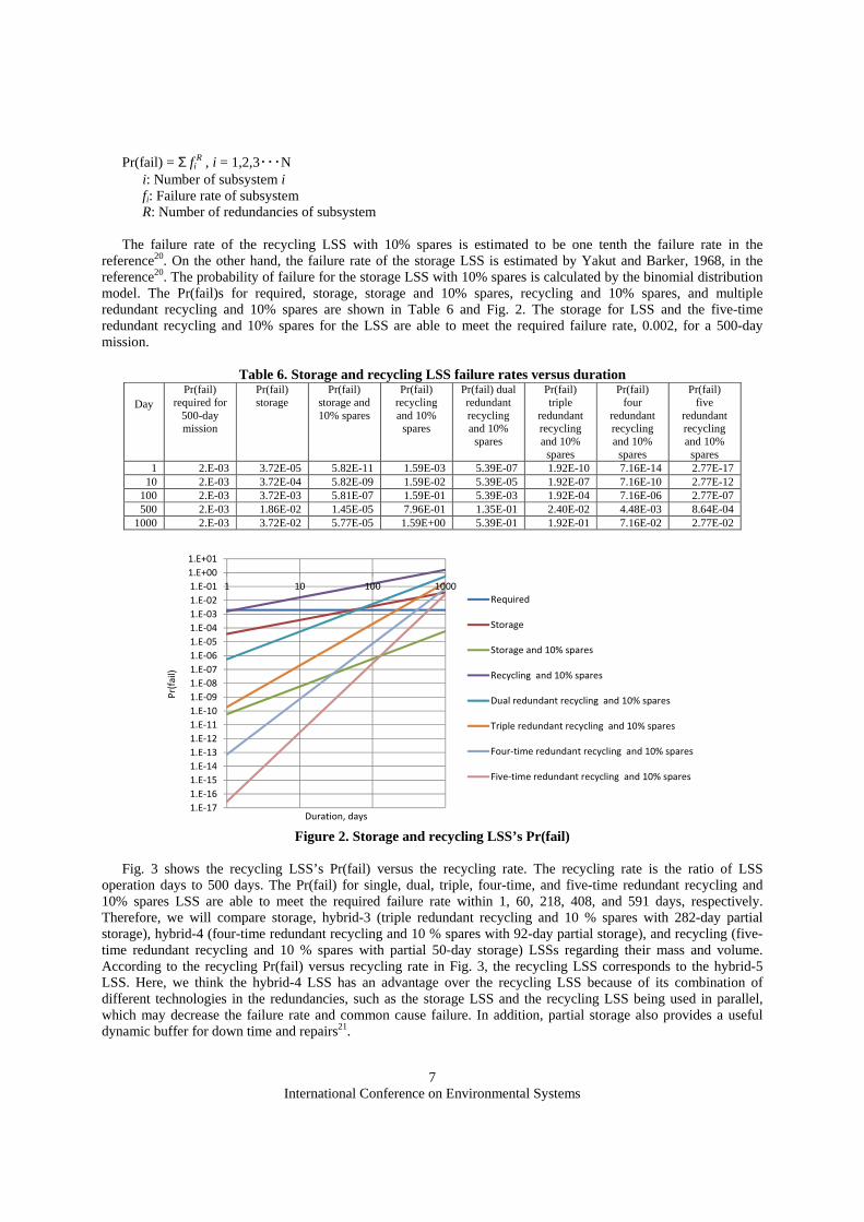
The failure rate of the recycling LSS with 10% spares is estimated to be one tenth the failure rate in the reference20. On the other hand, the failure rate of the storage LSS is estimated by Yakut and Barker, 1968, in the reference20. The probability of failure for the storage LSS with 10% spares is calculated by the binomial distribution model. The Pr(fail)s for required, storage, storage and 10% spares, recycling and 10% spares, and multiple redundant recycling and 10% spares are shown in Table 6 and Fig. 2. The storage for LSS and the five-time redundant recycling and 10% spares for the LSS are able to meet the required failure rate, 0.002, for a 500-day mission.
Table 6. Storage and recycling LSS failure rates versus duration
Day Pr(fail)
required for 500-day mission
Pr(fail) storage
Pr(fail) storage and 10% spares
Pr(fail) recycling and 10% spares
Pr(fail) dual redundant recycling and 10% spares
Pr(fail) triple
redundant recycling and 10% spares
Pr(fail) four
redundant recycling and 10% spares
Pr(fail) five
redundant recycling and 10% spares
1 2.E-03 3.72E-05 5.82E-11 1.59E-03 5.39E-07 1.92E-10 7.16E-14 2.77E-17 10 2.E-03 3.72E-04 5.82E-09 1.59E-02 5.39E-05 1.92E-07 7.16E-10 2.77E-12
100 2.E-03 3.72E-03 5.81E-07 1.59E-01 5.39E-03 1.92E-04 7.16E-06 2.77E-07 500 2.E-03 1.86E-02 1.45E-05 7.96E-01 1.35E-01 2.40E-02 4.48E-03 8.64E-04
1000 2.E-03 3.72E-02 5.77E-05 1.59E+00 5.39E-01 1.92E-01 7.16E-02 2.77E-02
1.E-17
1.E-16
1.E-15
1.E-14
1.E-13
1.E-12
1.E-11
1.E-10
1.E-09
1.E-08
1.E-07
1.E-06
1.E-05
1.E-04
1.E-03
1.E-02
1.E-01
1.E+00
1.E+01
1 10 100 1000
Pr(fail)
Duration, days
Required
Storage
Storage and 10% spares
Recycling and 10% spares
Dual redundant recycling and 10% spares
Triple redundant recycling and 10% spares
Four-time redundant recycling and 10% spares
Five-time redundant recycling and 10% spares
Figure 2. Storage and recycling LSS’s Pr(fail)
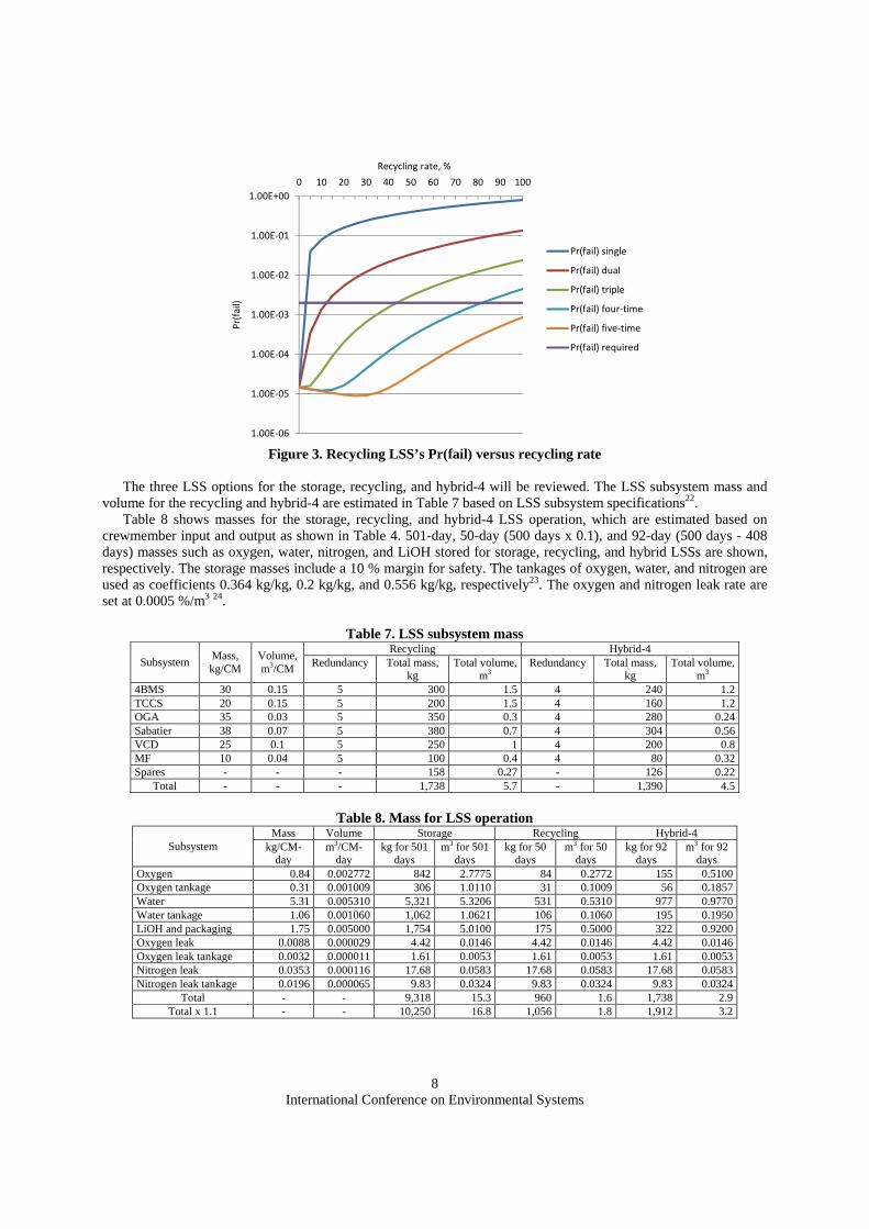
Fig. 3 shows the recycling LSS’s Pr(fail) versus the recycling rate. The recycling rate is the ratio of LSS
operation days to 500 days. The Pr(fail) for single, dual, triple, four-time, and five-time redundant recycling and 10% spares LSS are able to meet the required failure rate within 1, 60, 218, 408, and 591 days, respectively. Therefore, we will compare storage, hybrid-3 (triple redundant recycling and 10 % spares with 282-day partial storage), hybrid-4 (four-time redundant recycling and 10 % spares with 92-day partial storage), and recycling (five-time redundant recycling and 10 % spares with partial 50-day storage) LSSs regarding their mass and volume. According to the recycling Pr(fail) versus recycling rate in Fig. 3, the recycling LSS corresponds to the hybrid-5 LSS. Here, we think the hybrid-4 LSS has an advantage over the recycling LSS because of its combination of different technologies in the redundancies, such as the storage LSS and the recycling LSS being used in parallel, which may decrease the failure rate and common cause failure. In addition, partial storage also provides a useful dynamic buffer for down time and repairs21.
International Conference on Environmental Systems
8
1.00E-06
1.00E-05
1.00E-04
1.00E-03
1.00E-02
1.00E-01
1.00E+00
0 10 20 30 40 50 60 70 80 90 100
Pr(fail)
Recycling rate, %
Pr(fail) single
Pr(fail) dual
Pr(fail) triple
Pr(fail) four-time
Pr(fail) five-time
Pr(fail) required
Figure 3. Recycling LSS’s Pr(fail) versus recycling rate
The three LSS options for the storage, recycling, and hybrid-4 will be reviewed. The LSS subsystem mass and
volume for the recycling and hybrid-4 are estimated in Table 7 based on LSS subsystem specifications22. Table 8 shows masses for the storage, recycling, and hybrid-4 LSS operation, which are estimated based on
crewmember input and output as shown in Table 4. 501-day, 50-day (500 days x 0.1), and 92-day (500 days - 408 days) masses such as oxygen, water, nitrogen, and LiOH stored for storage, recycling, and hybrid LSSs are shown, respectively. The storage masses include a 10 % margin for safety. The tankages of oxygen, water, and nitrogen are used as coefficients 0.364 kg/kg, 0.2 kg/kg, and 0.556 kg/kg, respectively23. The oxygen and nitrogen leak rate are set at 0.0005 %/m3 24.
Table 7. LSS subsystem mass
Subsystem Mass, kg/CM
Volume, m3/CM
Recycling Hybrid-4 Redundancy Total mass,
kg Total volume,
m3 Redundancy Total mass,
kg Total volume,
m3 4BMS 30 0.15 5 300 1.5 4 240 1.2 TCCS 20 0.15 5 200 1.5 4 160 1.2 OGA 35 0.03 5 350 0.3 4 280 0.24 Sabatier 38 0.07 5 380 0.7 4 304 0.56 VCD 25 0.1 5 250 1 4 200 0.8 MF 10 0.04 5 100 0.4 4 80 0.32 Spares - - - 158 0.27 - 126 0.22
Total - - - 1,738 5.7 - 1,390 4.5
Table 8. Mass for LSS operation
Subsystem Mass Volume Storage Recycling Hybrid-4
kg/CM-day
m3/CM-day
kg for 501 days
m3 for 501 days
kg for 50 days
m3 for 50 days
kg for 92 days
m3 for 92 days
Oxygen 0.84 0.002772 842 2.7775 84 0.2772 155 0.5100 Oxygen tankage 0.31 0.001009 306 1.0110 31 0.1009 56 0.1857 Water 5.31 0.005310 5,321 5.3206 531 0.5310 977 0.9770 Water tankage 1.06 0.001060 1,062 1.0621 106 0.1060 195 0.1950 LiOH and packaging 1.75 0.005000 1,754 5.0100 175 0.5000 322 0.9200 Oxygen leak 0.0088 0.000029 4.42 0.0146 4.42 0.0146 4.42 0.0146 Oxygen leak tankage 0.0032 0.000011 1.61 0.0053 1.61 0.0053 1.61 0.0053 Nitrogen leak 0.0353 0.000116 17.68 0.0583 17.68 0.0583 17.68 0.0583 Nitrogen leak tankage 0.0196 0.000065 9.83 0.0324 9.83 0.0324 9.83 0.0324
Total - - 9,318 15.3 960 1.6 1,738 2.9 Total x 1.1 - - 10,250 16.8 1,056 1.8 1,912 3.2

International Conference on Environmental Systems
9
D. Evaluation of mission architecture using life cycle cost Life Cycle Cost (LCC)s for the storage, recycling, and hybrid-4 LSSs are estimated. LCC includes all costs
incurred during the development, launch, and operations of the space mission. The development and production cost can be estimated early in the conceptual design using the Advanced Mission Cost Model (AMCM) developed at Johnson Space Center25,26. This model consists of a single Cost Estimating Relationship (CER) relating a set of independent variables to the total system cost in FY 1999 dollars. The equation, derived using regression analysis, is
System Cost = 5.65 x 10⁻⁴ x Q0.5941 x (M/0.4536)0.6604 x 80.599 S x (3.8085 x 10-55(1/IOC-1900)) x B-0.3553 x 1.5691D where Q is the total quantity of development and production, M is the system dry mass, S specifies the type of mission (2.13 for human habitat, 2.27 for human reentry), IOC (Initial Operation Capability) is the first year of system operation, B is the hardware generation (1 for new design, 2 for second generation), and D is estimated difficulty (0 for average, 2.5 for very difficult, -2.5 for very easy).
The results of the development and production cost and the failure rate for the storage, recycling, and hybrid-4 LSSs are shown in Table 9. The development and production costs are $125M for storage, $821M for recycling, and $767M for hybrid. The cost of storage LSS is the lowest among three.
Table 9. Development and production cost for storage, recycling, and hybrid-4 LSSs LSS type Subsystem Q M S IOC B D $M
Storage LSS Oxygen tank 80 4.76 2.13 2017 20 -1 31 Water tank 80 14.84 2.13 2017 20 -1 66 LiOH canister 552 0.70 2.13 2017 20 -1 28
Total - - - - - - 125 Recycling LSS 4BMS 5 60 2.13 2017 4 1 140 TCCS 5 40 2.13 2017 4 1 107 OGA 5 70 2.13 2017 4 1 155 Sabatier 5 76 2.13 2017 2 1 209 VCD 5 50 2.13 2017 4 1 124 MF 5 20 2.13 2017 2 1 87 Oxygen tank 9 4.76 2.13 2017 20 -1 8 Water tank 9 14.84 2.13 2017 20 -1 18 LiOH canister 55 0.70 2.13 2017 20 -1 7
Total - - - - - - 821 Hybrid-4 LSS 4BMS 4 60 2.13 2017 4 1 122 TCCS 4 40 2.13 2017 4 1 94 OGA 4 70 2.13 2017 4 1 136 Sabatier 4 76 2.13 2017 2 1 183 VCD 4 50 2.13 2017 4 1 109 MF 4 20 2.13 2017 2 1 76 Oxygen tank 16 4.76 2.13 2017 20 -1 12 Water tank 16 14.84 2.13 2017 20 -1 25 LiOH canister 102 0.70 2.13 2017 20 -1 10
Total - - - - - - 767
In Table 10, the launch costs for the storage, recycling, and hybrid-4 LSSs are shown together for comparison.
The IMLEOs for three LSSs are calculated based on the burn-out mass, 36,237 kg. The launch costs for the three LSSs are calculated by the IMLEO multiplied by launch cost per kg. The launch cost per kg by the Falcon Heavy is set at $1454/kg 10 in the calculations. The launch costs for the storage, recycling, and hybrid-4 LSSs are $65M, $18M, and $21M, respectively, with the storage LSS cost being the largest among the three.
Table 10. Launch cost
Initial /final mass
ratio
Storage LSS
Recycling LSS
Hybrid-4 LSS
Mars Transit Vehicle, kg 36,237 - 10,250 2,794 3,303 IMLEO, kg 157,656 4.35 44,593 12,156 14,369 Launch cost (1454 $/kg x IMLEO), $M 229 - 65 18 21
Table 11 shows the LCC for the storage, recycling, and hybrid-4 LSSs, which is calculated by adding the
development and production, launch, and operation costs. The Johnson Space Center Mission Operations Cost Model (MOCM) estimates the operation cost as a percentage of the total development and production cost of

International Conference on Environmental Systems
10
spacecraft. For manned spacecraft, the operation cost per year is 10.9% of the total development and production cost. In this model, the operation cost is 10.9 % of the development and production cost 26. The LCCs are $209M, $962M, and $903M, respectively.
Table 11. Life Cycle Cost (LCC)
Storage
LSS, $M Percentages
Recycling LSS, $M
Percentage Hybrid-4 LSS, $M
Percentages
Development and production cost (DPC) 125 60% 821 85% 767 85% Launch cost (1454 $/kg x IMLEO) 65 31% 18 2% 21 2% Operation cost (DPC x 0.109 x 501/365) 19 9% 123 13% 115 13%
Total (LCC) 209 100% 962 100% 903 100%
Finally, the development and production costs for the CRV and the MTH are reviewed based on current existing
space systems shown in Table 12. Table 13 shows the development and production costs based on the specifications in Table 12. The cost for the CRV is estimated based on the Orion and Dragon vehicles. The cost for the MTH is estimated based on the Node 3, Cygnus, and HTV. The Table 13 shows the estimated cost of a new spacecraft derived from the existing one for the IM mission. The coefficients, 0.5 and 2.8, coordinate the required pressurized volume for this mission. The system generation (B) is 1, 2, 3, 2, and 2, for Orion, Dragon, Node 3, Cygnus, and HTV, respectively. The development difficulty (D) is 2, 2, 0, 1, and 0, respectively. Node 3 requires the smallest modification compared to the two cargo vehicles. The cost of the CRV is smaller when based on the small capsule, Dragon, as compared with one based on the large capsule, Orion. As the cost of the MTH is almost the same among the three habitat vehicles, another criterion is required for selecting original spacecraft that is best for reducing cost and time of development and production.
Table 12. Specification of crew vehicle and habitat vehicle
Specification Orion 27
Dragon Crew 28
Node 3 29
(ISS) Cygnus 30 (Cargo)
HTV 31 (Cargo)
Number of crew 2 - 4 Max 7 - - - Dry Mass, kg 9,684 4,200 12,471 1,500 10,500 Payload, kg 6,000 - 2,000 6,000 Pressurized Volume, m3 19.5 (Hab8.9) 10 70 18.9 14 Unpressurized Volume, m3 - - - - 16 Diameter, m 5.0 3.7 4.4 3.07 4.4 Length, m 3.3 2.9 7.2 3.66 9.8 Operation Term 21 -210 days Up to 2 years - 30 days 45 days Launch System Delta Heavy
(2014) SLS (2017-)
Falcon 9 Space Shuttle Antares HIIB
First operation 2019 2010 2010 2013 2010
Table 13. Development and production cost for CRV and MTH
Spacecraft System Q M S IOC B D $M CRV Orion x 0.5 1 4,842 2.27 2017 1 2 4,634 Dragon modified 1 2,681 2.27 2017 2 2 1,562 MTH Node 3 modified 1 12,471 2.13 2017 3 0 1,287 Cygnus x 2.8 1 5,040 2.13 2017 2 1 1,282 HTV modified 1 10,500 2.13 2017 2 0 1,327
E. System driver and critical requirement One of the authors of this paper, Miyajima, re-acknowledged the significance of a habitable volume when
designing the habitat facility for a long-term stay during the habitation experiment at the Mars Desert Research Station (MDRS) in 2013. In this mission design, the habitable volume is the system driver when designing the mission architecture and spacecraft. The reference13 defined the required habitable volume per crewmember as a function of mission duration and performance level: Tolerable 5.10 m3/CM, Performance 9.91 m3/CM, and Optimal 18.41 m3/CM. Design studies, such as the lunar surface system for the lunar surface mission32 and deep space habitat system for the Near Earth Asteroid (NEA) mission19 focus on habitable volume.
The IMLEOs for this design, shown in Fig. 4, are calculated using the rocket equations described in the above section III B, habitable volume and spacecraft mass, while varying the habitable volume per crewmember from 6 m3

International Conference on Environmental Systems
11
to 18 m3 (total pressurized volume is 24 m3 to 72 m3, which is double habitable volume). When the crew and the cargo is launched by three Falcon Heavy launches, the possible IMLEO is 159,000 kg, which corresponds to a volume less than 18 m3 habitable volume per crewmember (72 m3 total pressurized volume).
Table 14 shows the details of trade tree options 7-12 previously shown in Table 4, which are a combination of the multiple launch mission concept, commercial based CRV development, habitable volume per crewmember of 18 m3 or 6 m3, and an ECLSS type of storage, recycling, or hybrid-4. We assume that the volume for water and oxygen, and nitrogen is not included in the pressurized volume. Comparing the total pressurized volume of 24 m3 to the volume for the consumable crew supply plus volume for the storage, recycling, and hybrid-4 LSSs of 19.2 m3, 19.9 m3, and 19.2 m3, respectively, we identify they all occupy more than 80 %, 83 %, and 80 % of the total pressurized volume respectively, Meaning there is not enough volume capacity for a crew to live. This indicates that such a spacecraft is not possible.
Although there are no problems with the volume when the habitable volume per crewmember is 18 m3, the IMLEO at 184,656 kg for the storage LSS exceeds the possible launch payload of 159,000 kg. Therefore, the recycling LSS and the hybrid-4 LSS remain the only options when the habitable volume per crewmember is 18 m3. We thought the hybrid-4 LSS had an advantage over the recycling LSS previously shown in Section III C because a combination of different technologies in the redundancies, such as the storage LSS and the recycling LSS used in parallel, is able to decrease the failure rate and common cause failure.
0
20,000
40,000
60,000
80,000
100,000
120,000
140,000
160,000
180,000
200,000
6 7 8 9 10 11 12 13 14 15 16 17 18
IMLE
O,
kg
Habitable volume, m3/CM
Storage
Recycling
Hybrid-4
Figure 4. Habitable volume per crewmember vs. IMLEO
Table 14. Comparison of habitable volume, CS volume, and LSS volume
Option Habitable volume, m3/CM
ECLSS type
Launch System
Number of launches
Payload to LEO,
kg
Required IMLEO,
kg
Total pressurized volume, m3
CS volume*1,
m3
LSS volume*2,
m3
LSS volume*3,
m3
CS and LSS volume*4,
m3 Evaluation
7 18
Storage Falcon 3 159,000 184,657 72 13.7 16.8 5.5 19.2 8 Recycling Heavy 3 159,000 156,222 72 13.7 7.5 6.2 19.9 x 9 Hybrid-4 3 159,000 157,656 72 13.7 7.7 5.5 19.2 x 10
6 Storage 3 159,000 149,931 24 13.7 16.8 5.5 19.2
11 Recycling 3 159,000 121,496 24 13.7 7.5 6.2 19.9 12 Hybrid-4 3 159,000 122,930 24 13.7 7.7 5.5 19.2
*1 0.0137 x 2 x 501 (ref. Table 5) *2 LSS volume for LSS subsystem, LiOH, water, oxygen, and nitrogen (ref. Table 8) *3 LSS volume for LSS subsystem and LiOH (ref. Table 8) *4 CS volume + LSS volume for LSS subsystem and LiOH (ref. Table 8)
IV. Baseline concept and architecture The reference mission and concept of operation for Option 9 is shown in Fig. 5. The layout of the designed
spacecraft consisting of a CRV based on the Dragon and an MTH based on Node 3 is shown in Fig. 6. The mass budget and the volume distribution are shown in Table 15 and 16.
In this mission concept, first one crew launch and two cargo launches are carried out. Then three space elements such as the CRV, MTH, and TMI booster rendezvous and dock with each other at LEO. This is followed by the docked spacecraft reaching Mars after the TMI burn stage, a flyby on Mars, a return to Earth using the free return

International Conference on Environmental Systems
12
trajectory, and a reentry into Earth’s atmosphere. The assembly of the space elements can be done using current existing technology and the ISS operation resource, such as the ground system and human resources. Therefore, new investment and training for the mission operation will be at a minimum. Therefore, the total cost, $3,504 M, can be estimated as shown in Table 17 based on the LCC in Table 13.
501-day Transit
Mars Encounter and Flyby
Reenters Earth Atm.
CRV, MTV, and TMI booster rendezvous
Crew Mission Launch
x 1
Cargo Mission Launch
x 2
Trans-Mars Injection (TMI) burn
Figure 5. IM Reference Mission/Concept of operation
7.2 m 2.9 m10 m
TMI BoosterProp Sys 9,059kg
Prop Fuel 120,603 kgPressurized
volume62 m3
MTH18,146 kg
3.7 m
CRV2,681 kg
10 m3
4.4 m
Crew supply 6,900 kg, 13.7 m3; Hybrid-4 LSS Logistics 3,284 kg, 7.7m3
Figure 6. Mass and volume budget of CRV and MTH
Table 15. Mass budget for MTH and CRV Mass budget Initial mass, kg
Structure 4,022 Mechanisms 1,564 Thermal protection 1,787 Attitude control 447 Power 2,681 Avionics and control 1,787 ECLSS (Hybrid-4 LSS) 1,390 Crew accommodations 1,787 CRV 2,681
Dry mass without propulsion system 18,146 Propulsion system 9,059
Dry mass 27,205 Crew 220 Crew supply and LSS consumables 8,812
Dry mass + Crew + consumables 36,237 Main propellant 120,603 Propellant for attitude control 816
Gross mass estimate 157,656
International Conference on Environmental Systems
13
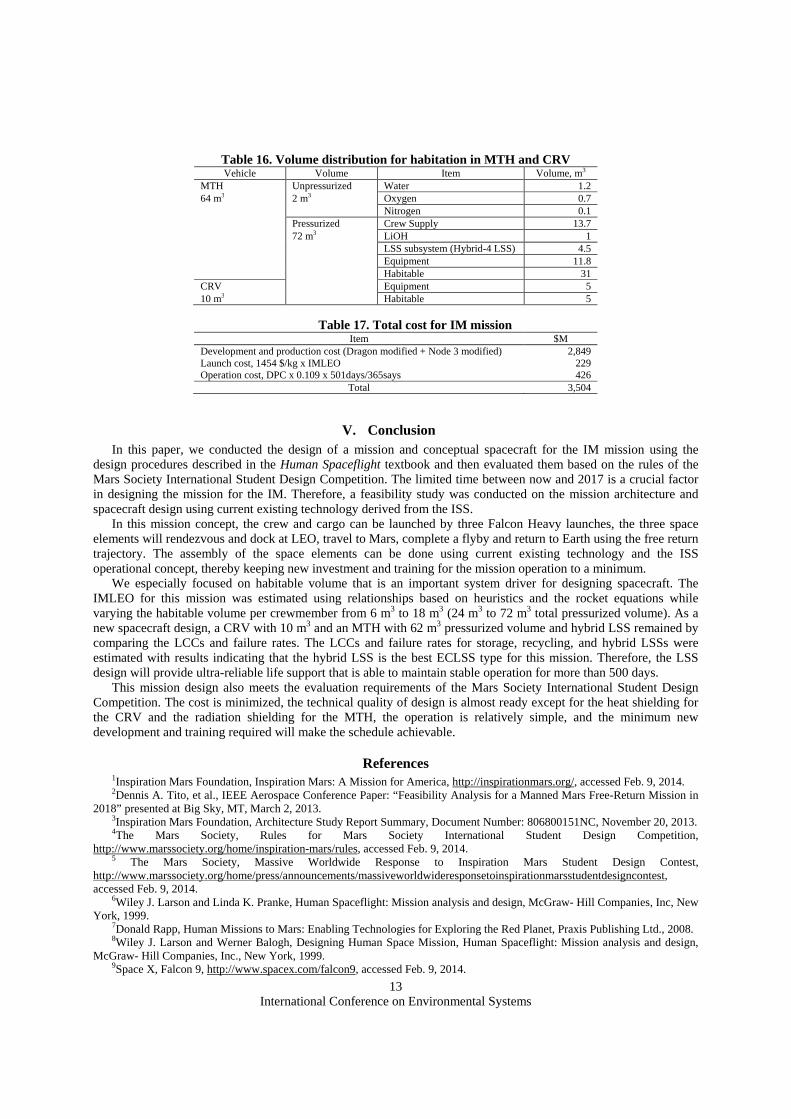
Table 16. Volume distribution for habitation in MTH and CRV Vehicle Volume Item Volume, m3
MTH Unpressurized Water 1.2 64 m3 2 m3 Oxygen 0.7 Nitrogen 0.1 Pressurized Crew Supply 13.7 72 m3 LiOH 1 LSS subsystem (Hybrid-4 LSS) 4.5 Equipment 11.8 Habitable 31 CRV Equipment 5 10 m3 Habitable 5
Table 17. Total cost for IM mission Item $M
Development and production cost (Dragon modified + Node 3 modified) 2,849 Launch cost, 1454 $/kg x IMLEO 229 Operation cost, DPC x 0.109 x 501days/365says 426
Total 3,504
V. Conclusion In this paper, we conducted the design of a mission and conceptual spacecraft for the IM mission using the
design procedures described in the Human Spaceflight textbook and then evaluated them based on the rules of the Mars Society International Student Design Competition. The limited time between now and 2017 is a crucial factor in designing the mission for the IM. Therefore, a feasibility study was conducted on the mission architecture and spacecraft design using current existing technology derived from the ISS.
In this mission concept, the crew and cargo can be launched by three Falcon Heavy launches, the three space elements will rendezvous and dock at LEO, travel to Mars, complete a flyby and return to Earth using the free return trajectory. The assembly of the space elements can be done using current existing technology and the ISS operational concept, thereby keeping new investment and training for the mission operation to a minimum.
We especially focused on habitable volume that is an important system driver for designing spacecraft. The IMLEO for this mission was estimated using relationships based on heuristics and the rocket equations while varying the habitable volume per crewmember from 6 m3 to 18 m3 (24 m3 to 72 m3 total pressurized volume). As a new spacecraft design, a CRV with 10 m3 and an MTH with 62 m3 pressurized volume and hybrid LSS remained by comparing the LCCs and failure rates. The LCCs and failure rates for storage, recycling, and hybrid LSSs were estimated with results indicating that the hybrid LSS is the best ECLSS type for this mission. Therefore, the LSS design will provide ultra-reliable life support that is able to maintain stable operation for more than 500 days.
This mission design also meets the evaluation requirements of the Mars Society International Student Design Competition. The cost is minimized, the technical quality of design is almost ready except for the heat shielding for the CRV and the radiation shielding for the MTH, the operation is relatively simple, and the minimum new development and training required will make the schedule achievable.
References 1Inspiration Mars Foundation, Inspiration Mars: A Mission for America, http://inspirationmars.org/, accessed Feb. 9, 2014. 2Dennis A. Tito, et al., IEEE Aerospace Conference Paper: “Feasibility Analysis for a Manned Mars Free-Return Mission in
2018” presented at Big Sky, MT, March 2, 2013. 3Inspiration Mars Foundation, Architecture Study Report Summary, Document Number: 806800151NC, November 20, 2013. 4The Mars Society, Rules for Mars Society International Student Design Competition,
http://www.marssociety.org/home/inspiration-mars/rules, accessed Feb. 9, 2014. 5 The Mars Society, Massive Worldwide Response to Inspiration Mars Student Design Contest,
http://www.marssociety.org/home/press/announcements/massiveworldwideresponsetoinspirationmarsstudentdesigncontest, accessed Feb. 9, 2014.
6Wiley J. Larson and Linda K. Pranke, Human Spaceflight: Mission analysis and design, McGraw- Hill Companies, Inc, New York, 1999.
7Donald Rapp, Human Missions to Mars: Enabling Technologies for Exploring the Red Planet, Praxis Publishing Ltd., 2008. 8Wiley J. Larson and Werner Balogh, Designing Human Space Mission, Human Spaceflight: Mission analysis and design,
McGraw- Hill Companies, Inc., New York, 1999. 9Space X, Falcon 9, http://www.spacex.com/falcon9, accessed Feb. 9, 2014.

International Conference on Environmental Systems
14
10Space X, Falcon Heavy, http://www.spacex.com/falcon-heavy, accessed Feb. 9, 2014. 11NASA, Space Launch System (SLS) Fun Facts, FS-2012-01-11-MSFC, 2012. 12Boeing, Delta IV Overview, http://www.boeing.com/boeing/defense-space/space/delta/delta4/delta4.page, accessed Feb. 9,
2014. 13NASA, Man-System Integration Standards, NASA STD-3000, 1995. 14NASA, Mass Estimating and Forecasting for Aerospace Vehicles, NASA Johnson Space Center Systems Definition Branch,
1994. 15Andrew Petro, Transfer, Entry, Landing, and Ascent Vehicles, Human Spaceflight: Mission analysis and design, McGraw-
Hill Companies, Inc., New York, 1999. 16NASA, International Space Station 6-Crew Strategic Planning Document, SSP50826, 2008. 17NASA, NASA facts: International Space Station Environmental Control and Life Support System, FS-2008-05-83-MSFC,
2008. 18Harry W. Jones, Gregory S. Pace, and John W. Fisher, Managing Spacecraft Waste Using the Heat Melt Compactor, 43rd
International Conference on Environmental Systems, AIAA 2013-3362, 2013. 19Michelle A. Rucker, DEVELOPING A HABITAT FOR LONG DURATION, DEEP SPACE MISSIONS, GLEX-
2012.05.3.8x12222, 2012. 20Harry W. Jones, Design and Analysis of a Flexible, Reliable Deep Space Life Support System, 42nd International
Conference on Environmental Systems, AIAA 2012-3418, 2012. 21Harry W. Jones, Storage or Recycling Life Support for Mars?, 43rd International Conference on Environmental Systems,
AIAA 2013-3407, 2013. 22Susan Doll and Peter Eckart, Environmental Control and Life Support Systems (ECLSS), Human Spaceflight: Mission
analysis and design, McGraw- Hill Companies, Inc., New York, 1999. 23Hanford, A. J., Advanced Life Support Baseline Values and Assumptions Document, NASA, CR-2004-208941, 2004. 24Lange, K. E. and Lin, C. H., 1998: Advanced Life Support Program - Requirements Definition and Design Considerations,
NASA, Technical Report CTSD-ADV-245, 1996.
25Federation of American Scientists (FAS), Online Advanced Missions Cost Model (AMCM), http://www.fas.org/news/reference/calc/AMCM.htm, NASA, Technical Report CTSD-ADV-245, 1996.
26Lisa Guerra and Robert Shishko, Estimating the Cost of Crewed Space Systems, Human Spaceflight: Mission analysis and design, McGraw- Hill Companies, Inc., New York, 1999.
27NASA, NASA Facts: Orion Quick Facts, FS-2011-12-058-JSC, 2011. 28Space X, Dragon, http://www.spacex.com/dragon, accessed Feb. 9, 2014. 29ESA, Node-3 (Tranquility), ESA-HSO-COU-006, 2014. 30Orbital, Fact Sheet: Cygnus Advanced Maneuvering Spacecraft, FS006_08_2706, 2014. 31ESA, H-II Transfer Vehicle (HTV), ESA-HSO-COU-031, http://wsn.spaceflight.esa.int/, accessed Feb. 9, 2014. 32Marianne Rudisill, Lunar Architecture Team: Phase 2 Habitat Volume Estimation: Caution When Using Analogs, Earth &
Space 2008: Engineering, Science, Construction, and Operations in Challenging Environments, 2008. 33John F. Connolly, Mars Design Example, Human Spaceflight: Mission analysis and design, McGraw- Hill Companies, Inc.,
New York, 1999.