FEA Report in Inventor Professional 2014 -...
5
We are in the elastic zone where we assume the material fully recovers to its preloaded state when loads are removed; as a consequence the simulation excludes post yielding, plastic and large deformation, large strains, the effects of orthotropic and anisotropic material behavior and more. The assumption applies to material linearity where stress-strain ratios are constant during the loading. (no time variation of it) Element compatibility and constitutive relationships are linear and the stiffness matrix does not change. Equilibrium is satisfied in the un-deformed configuration. Displacements are directly proportional to the loads; stress is directly proportional to strain. Make sure that these underlying assumptions are valid for your model behavior otherwise the results could lead to irrelevant and incorrect design conclusions. In cases where your model operates outside of the linear region, consider further investigation using simulation resources that can account for nonlinear behavior. Autodesk Simulation Mechanical 2014 provides extensive capabilities for such simulations needs. TECHNICAL WHITEPAPER Assumptions of the Linear Static Analysis Legend (color bar) Settings Report Format Publish stress analysis results in DWF, DWFX, PDF About the Author: Radu Stancescu In This Issue Generating a report of an analysis simulation shouldn’t be a challenge for any Inventor user. I will be covering the following topics in this current article: Linear Static Analysis Assumptions, Legend Settings, Report Format, Publish Results in DWF, DWFX and PDF documents. Assumptions of the Linear Static Analysis Before diving into the “report zone” there are some things we need to be aware of first: FEA Report in Inventor Professional 2014 June 2013
Transcript of FEA Report in Inventor Professional 2014 -...
We are in the elastic zone where we assume the material fully recovers to its preloaded state when loads are removed; as a consequence the simulation excludes post yielding, plastic and large deformation, large strains, the effects of orthotropic and anisotropic material behavior and more.
The assumption applies to material linearity where stress-strain ratios are constant during the loading. (no time variation of it)
Element compatibility and constitutive relationships are linear and the stiffness matrix does not change.
Equilibrium is satisfied in the un-deformed configuration.
Displacements are directly proportional to the loads; stress is directly proportional to strain.
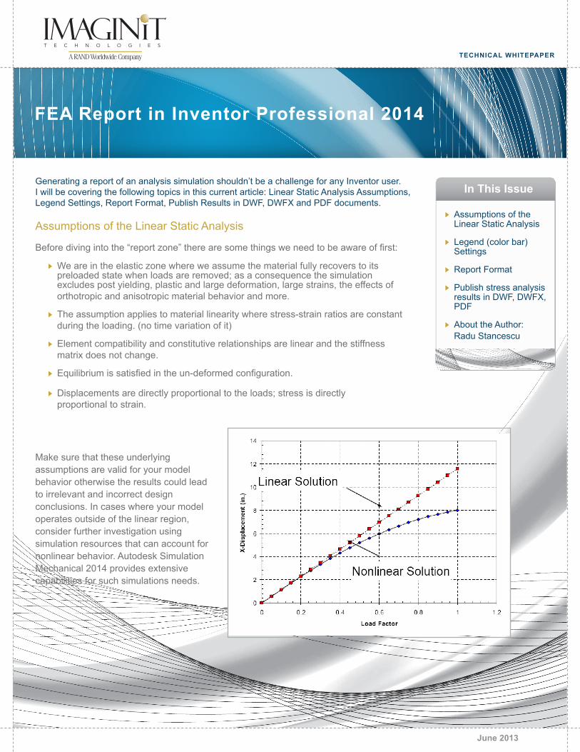
Make sure that these underlying assumptions are valid for your model behavior otherwise the results could lead to irrelevant and incorrect design conclusions. In cases where your model operates outside of the linear region, consider further investigation using simulation resources that can account for nonlinear behavior. Autodesk Simulation Mechanical 2014 provides extensive capabilities for such simulations needs.
TECHNICAL WHITEPAPER
Assumptions of the Linear Static Analysis
Legend (color bar) Settings
Report Format
Publish stress analysis results in DWF, DWFX, PDF
About the Author: Radu Stancescu
In This IssueGenerating a report of an analysis simulation shouldn’t be a challenge for any Inventor user. I will be covering the following topics in this current article: Linear Static Analysis Assumptions, Legend Settings, Report Format, Publish Results in DWF, DWFX and PDF documents.
Assumptions of the Linear Static Analysis
Before diving into the “report zone” there are some things we need to be aware of first:
FEA Report in Inventor Professional 2014
June 2013
imaginit.comPage 2 • FEA Report in Inventor Professional 2014
Legend (color bar) Settings
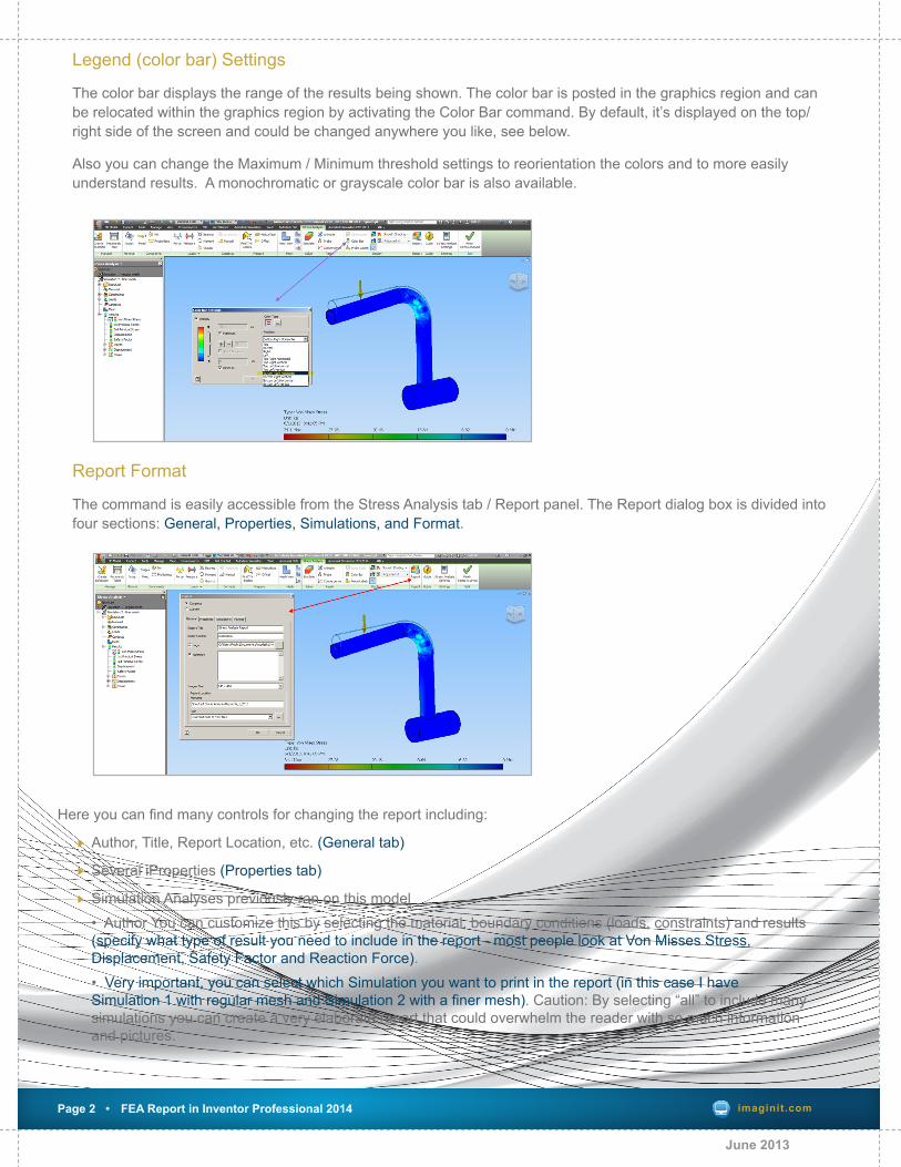
The color bar displays the range of the results being shown. The color bar is posted in the graphics region and can be relocated within the graphics region by activating the Color Bar command. By default, it’s displayed on the top/right side of the screen and could be changed anywhere you like, see below.
Also you can change the Maximum / Minimum threshold settings to reorientation the colors and to more easily understand results. A monochromatic or grayscale color bar is also available.
June 2013
Report Format
The command is easily accessible from the Stress Analysis tab / Report panel. The Report dialog box is divided into four sections: General, Properties, Simulations, and Format.
Here you can find many controls for changing the report including:
Author, Title, Report Location, etc. (General tab)
Several iProperties (Properties tab)
Simulation Analyses previously ran on this model • Author You can customize this by selecting the material, boundary conditions (loads, constraints) and results (specify what type of result you need to include in the report - most people look at Von Misses Stress, Displacement, Safety Factor and Reaction Force). • Very important, you can select which Simulation you want to print in the report (in this case I have Simulation 1 with regular mesh and Simulation 2 with a finer mesh). Caution: By selecting “all” to include many simulations you can create a very elaborate report that could overwhelm the reader with so much information and pictures.
imaginit.comPage 3 • FEA Report in Inventor Professional 2014
June 2013
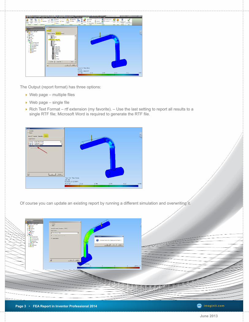
The Output (report format) has three options:
Web page – multiple files
Web page – single file Rich Text Format – rtf extension (my favorite). – Use the last setting to report all results to a single RTF file; Microsoft Word is required to generate the RTF file.
Of course you can update an existing report by running a different simulation and overwriting it.
imaginit.comPage 4 • FEA Report in Inventor Professional 2014
Publish stress analysis results in DWF, DWFX, PDF
Autodesk data can be published in DWF format and viewed using Autodesk Design Review. Viewing and sharing data is an important tool when communicating with vendors and customers. Anyone can use published DWF files, even without installing Autodesk Inventor. DWF files are highly compressed, fast to open and view and you can share them by email.
Publishing from Autodesk Inventor creates a DWF file that maintains design data such as line weights, scale, and mass properties for 2D and 3D files. Both 2D and 3D data can be included in one file.
The stress analysis results display the model in various colors according to the intensity of the applied forces and constraints.
While working in the Stress Analysis environment, you can use the various display commands to create the view you want to export to DWF.
In the simulation browser bar, select and display the results that you want to see in Autodesk Design Review.
The current state of the part or assembly model is published in the DWF file.
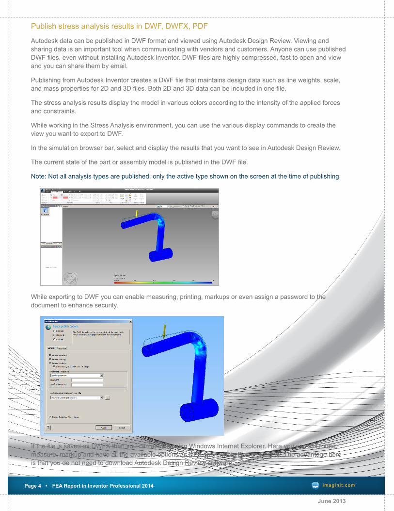
Note: Not all analysis types are published, only the active type shown on the screen at the time of publishing.
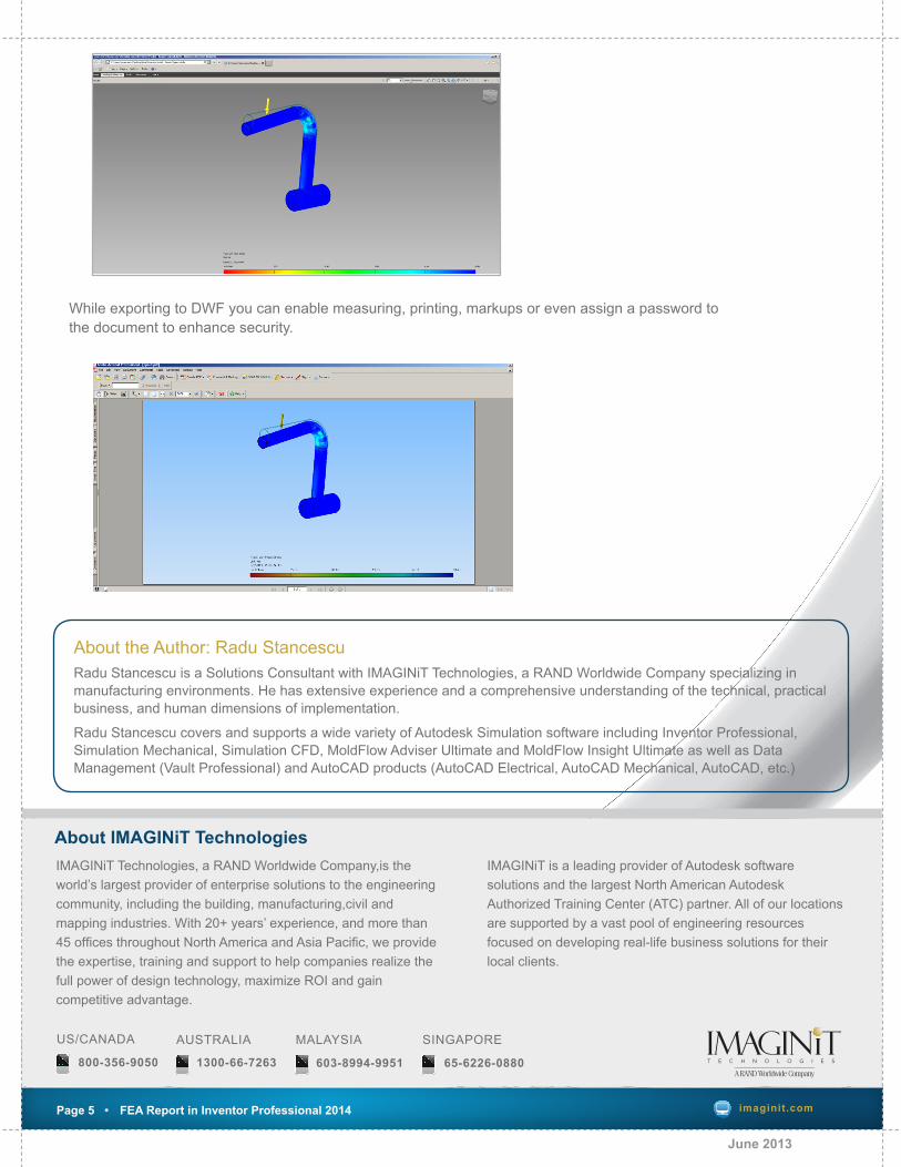
While exporting to DWF you can enable measuring, printing, markups or even assign a password to the document to enhance security.
June 2013
If the file is saved as DWFX then you can open it using Windows Internet Explorer. Here you can still rotate, measure, markup and have all the available options as if it’s open within Design Review. The advantage here is that you do not need to download Autodesk Design Review software.
US/CANADA
800-356-9050
MALAYSIA
603-8994-9951
SINGAPORE
65-6226-0880
AUSTRALIA
1300-66-7263
Page 5 • Performance Tips for Civil 3D 2012 (Part 1) imaginit.comPage 5 • FEA Report in Inventor Professional 2014
IMAGINiT Technologies, a RAND Worldwide Company,is the world’s largest provider of enterprise solutions to the engineering community, including the building, manufacturing,civil and mapping industries. With 20+ years’ experience, and more than 45 offices throughout North America and Asia Pacific, we provide the expertise, training and support to help companies realize the full power of design technology, maximize ROI and gain competitive advantage.
IMAGINiT is a leading provider of Autodesk software solutions and the largest North American Autodesk Authorized Training Center (ATC) partner. All of our locations are supported by a vast pool of engineering resources focused on developing real-life business solutions for their local clients.
About IMAGINiT Technologies
About the Author: Radu Stancescu Radu Stancescu is a Solutions Consultant with IMAGINiT Technologies, a RAND Worldwide Company specializing in manufacturing environments. He has extensive experience and a comprehensive understanding of the technical, practical business, and human dimensions of implementation.
Radu Stancescu covers and supports a wide variety of Autodesk Simulation software including Inventor Professional, Simulation Mechanical, Simulation CFD, MoldFlow Adviser Ultimate and MoldFlow Insight Ultimate as well as Data Management (Vault Professional) and AutoCAD products (AutoCAD Electrical, AutoCAD Mechanical, AutoCAD, etc.)
June 2013
While exporting to DWF you can enable measuring, printing, markups or even assign a password to the document to enhance security.