FE model of a car seat - TU/e · PDF fileat several points, e.g. the mesh and the material...
42
Report nr: BMT02.06 Raimond Haan January 2002 Netherlands Organisation for Applied Scientific Research Eindhoven University of Technology. Department Mechanical Engineering FE model of a car seat Creating an assessment tool for comfort analysis
Transcript of FE model of a car seat - TU/e · PDF fileat several points, e.g. the mesh and the material...

Report nr: BMT02.06
Raimond Haan
January 2002
Netherlands Organisation forApplied Scientific Research
Eindhoven University ofTechnology. DepartmentMechanical Engineering
FE model of a car seatCreating an assessment tool for comfort analysis
1
FE model of a car seat
TNO/WT/BV/R&D, Mechanical Engineering EUT / © 2002
TNO Automotive is an institute that carries out research and provides services in the field ofroad vehicles and their components. The primary areas of attention are Vehicle Dynamics,Crash Safety, Combustion Engines and Homologations.
Research information
Performed at: Institute: TNO AutomotiveDepartment: Crash Safety CentreSection: Research & DevelopmentSubsection: Biomechanics
Research period: September 10th, 2001 • January 25th, 2002
Committee: Prof. Dr. Ir. J.S.H.M. Wismans (TNO / EUT)
Dr. Ir. C.W.J. Oomens (EUT)
Dr. Ir. J. van Hoof (TNO / EUT)
Ir. M.M. Verver (TNO / EUT)
Student: Raimond J.G. HaanStudentnr.: 433735
Netherlands Organisation forApplied Scientific Research (TNO)
TNO Automotive
Crash Safety CentreSchoemakerstraat 97P.O. Box 60332600 JA DelftThe Netherlands
www.tno.nl
Phone +31 15 2696900Fax +31 15 2624321
Eindhoven University of Technology(EUT)
Department of Mechanical EngineeringSection: Automotive
TU/eDen Dolech 2P.O. Box 5135600 MB EindhovenThe Netherlands
www.tue.nl
Phone +31 40 2472851Fax +31 40 2447355
All rights reserved. No part of this publication may bereproduced and/or published by print, photoprint, microfilm orany other means without the previous written consent of TNO.

2
FE model of a car seat
TNO/WT/BV/R&D, Mechanical Engineering EUT / © 2002
Abstract
A vehicle seat has to be both safe and comfortable at the same time, which means that thedesign has to fulfil different functionalities. Until now, the design and introduction of a newseat is a very costly and time-consuming process. During the design phase several prototypesare build in order to be evaluated by a jury. Using computer models could make it possible tointegrate both safety and comfort in the design process. Besides that, the use of computermodels saves time by shortening the design cycle, because prediction of parameters related tocomfort by simulations reduces the amount of prototypes that has to be made. Literatureshows that pressure distributions can be regarded as an objective parameter for seatingcomfort.
The available models of seats at TNO are based on multibody techniques (MB), and do notallow deformations. Deformability of the contact surfaces from both seat and occupant isrequired if computer models are used to predict pressure distributions on the contact surfacesbetween occupant and seat. Models based on the finite element (FE) method are capable ofsimulating these required deformations.
The objective of this project is to create a FE-model of a standard car seat, which offersprediction of objective comfort parameters in the means of pressure distributions. This will inthe future result in objective assessment tools for virtual testing of automotive seating comfortduring the design phase of new seats. An existing multibody model of a Volvo V40 seat hadto be converted into a FE-model. In this project MADYMO v6.0 is used.
First the seat was examined by disassembling the seat in order to explore the geometries ofthe different components and to determine the materials and mechanical properties. Next therewas an evaluation of the FE-method, a survey to the element types, material models andassumptions for the different components of the seat model. Also methods for the connectionsbetween the different components have been evaluated. After creating and meshing thegeometry of the different components they have been implemented into a MADYMO v6.0model that simulates already performed tests with anthropometrical shapes. Materialproperties were assigned to this model.
The simulations that had been performed with the seat cushion part show that it is possible tohave a representation of the pressure distributions of a representative buttock and to virtuallymodel and test seat components under dynamic loading. The model will have to be improvedat several points, e.g. the mesh and the material model of the polyurethane foam. Thegeometry of the frame seat back has to be modelled and meshed. The solid mesh of the seatcushion needs enhancement in the means of adjusting critical elements in the mesh. After thatthe contact characteristics have to be improved. Once the mesh and contact are improved andthe model validated, all components are ready for a full comfort analysis of the seat. It hasbecome clear that the FE-model has the potential to result in an objective assessment tool tosupport virtual testing of automotive seating comfort during the design phase of newcomfortable seats.

3
FE model of a car seat
TNO/WT/BV/R&D, Mechanical Engineering EUT / © 2002
Preface
During five and a half month I performed my practical training for my study MechanicalEngineering, department Automotive, at Eindhoven University of Technology (EUT). I wouldlike to take this opportunity to acknowledge a few people for their support and advise duringthe time of this project, performed at TNO Automotive, department Crash Safety Centre,R&D in Delft.
First, I would like to thank Prof. Wismans for offering me the opportunity to perform thisprovocative and educational apprenticeship at TNO Automotive. I would also like to thankmy supervisor from EUT Cees Oomens and my supervisor at TNO Jack van Hoof for theircritical comments and knowledge. Special thanks go out to my tutor Murielle Verver, whotook on the daily supervision, for her good advice and critical comments. Further, I would liketo thank all my colleagues at TNO Automotive, especially those working at the Crash SafetyCentre for their companionship. Last but definitely not least, I want to thank Ronald de Langefor his great support and effort.

4
FE model of a car seat
TNO/WT/BV/R&D, Mechanical Engineering EUT / © 2002
Table of contents
Abstract.............................................................................................................................................2
Preface...............................................................................................................................................3
1 Introduction ............................................................................................................................51.1 Background.......................................................................................................................51.2 Objective...........................................................................................................................61.3 Strategy.............................................................................................................................6
2 Automotive seats .....................................................................................................................72.1 Introduction.......................................................................................................................72.2 Construction of the seat .....................................................................................................72.2.1 Metal frame ...................................................................................................................82.2.2 Headrest ........................................................................................................................82.2.3 Trampolines...................................................................................................................82.2.4 Foam components ..........................................................................................................9
3 FE seat model – set-up and assumptions..............................................................................103.1 MADYMO......................................................................................................................103.2 Link of theory to model – assumptions.............................................................................103.3 Element types and material models ..................................................................................103.3.1 Metal frame .................................................................................................................103.3.2 Headrest ......................................................................................................................113.3.3 Trampolines.................................................................................................................113.3.4 Springs ........................................................................................................................113.3.5 Foam components ........................................................................................................123.4 Connection of the different components...........................................................................153.5 Geometry ........................................................................................................................183.5.1 Hypermesh ..................................................................................................................183.5.2 Geometric assumptions ................................................................................................183.5.3 Mesh density................................................................................................................193.5.4 Results.........................................................................................................................203.6 Summary of the model set-up and assumptions ................................................................21
4 Validation of the FE seat model ...........................................................................................224.1 Performed tests................................................................................................................224.2 Simulation.......................................................................................................................23
5 Conclusion and Recommendations ......................................................................................245.1 Conclusion ......................................................................................................................245.2 Recommendations ...........................................................................................................24
References .......................................................................................................................................25
Appendix A: FE Method - Theoretical Introduction...................................................................27
Appendix B: Foam material .........................................................................................................29B.1 Stress-strain response under uniaxial compression for different strain rates ......................29B.2 Determination of strain rate dependent scaling factors.....................................................31
Appendix C: Solid element comparison for foam mesh...............................................................32C.1 Comparison by basic loading conditions ..........................................................................32C.2 Element stiffness comparison to theoretical solution ........................................................36
Appendix D: Pictures from the final seat cushion model.............................................................39
Appendix E: Set-up for experiments with the foam material......................................................40

5
FE model of a car seat
TNO/WT/BV/R&D, Mechanical Engineering EUT / © 2002
1 Introduction
1.1 Background
Comfort is a burning issue in the automotive industry, since it is a way for manufacturers todistinguish themselves from concurrent manufacturers. Besides that, customers are expectinga higher level of comfort, since they have the ability to spend extra money due to the risingprosperity. As customer expectations rise, automotive seating comfort is becoming anincreasingly important design goal.
The concept of ‘comfort’ is very complicated and related to subjective impressions that areactivated by environmental factors such as sound, sight, heat and feeling. In the automotiveseating industry there has been a struggle to define seating comfort in an objective manner.Due to the lack of objective parameters, the seat manufacturers have relied on jury evaluationsas the main measure of seating comfort. This trial-and-error approach is very time-consumingand expensive.
With the advancement of technology, several objective parameters of seating comfort haveevolved. None of these objective measurables has emerged as a singular predictor of seatingcomfort, but a combination of them may lead to a better understanding of designing acomfortable seat. As the technologies progress it is almost certain that in the future certainstandard objective measures of seating comfort will evolve. By now, several objectiveparameters are believed to have some correlation to comfort [1]:
- muscle activity that can measured by electromyography (EMG),- spinal loading: measured by an increase/decrease in spinal length,- body motion: defined by the amount of times a driver adjusts his/her position, and- pressure distributions: aspects such as maximum pressure, average pressure, average
gradients and maximum gradients are taken into account.
This study focuses on pressure distributions as an objective parameter in seating comfort.Literature shows that the pressure distribution on the contact surface between occupant andseat is important in examining whether a seat is comfortable or not. Kamijo et al. [2] showed ageneral trend relating the seat-body pressure distribution (symmetry) to (static) sittingcomfort. Milvojevich et al. [3] described a (non-quantified) correlation between seat-bodypressure distribution and (static) comfort. Uenishi et al. [4] showed that their index onpressure distribution (static/dynamic) showed a good relationship with sitting comfort duringvibrations. Inagaki et al. [5] demonstrated that seat compliance (a combination of seatdeformation and pressure distribution) is related to (static) sitting comfort. The studies byZhao et al. [6] and Park et al [7] provided statistically significant relationships between driver-seat pressure variables and (static) sitting comfort. Park et al. [7] started in their article withan investigation of correlation between the body pressure and the subjective evaluation of thedriver seat. It was checked whether the body pressure distribution could be regarded as anobjective measure to evaluate comfort. The performed experiments showed that forcomfortable seats, the body pressure was distributed well and symmetrically centring aroundthe ischial tuberosities (sit bones). The authors state that pressure distribution can be regardedas an objective parameter for seating comfort.

6
FE model of a car seat
TNO/WT/BV/R&D, Mechanical Engineering EUT / © 2002
For manufacturers, the ability to predict the interaction between occupant and seat by virtualtesting, taking into account the deformations from both seat and occupant, is an important toolin the design process of new comfortable seats. Until now, the design and introduction of anew seat is a very costly and time-consuming process. During the design phase severalprototypes are build in order to be evaluated by a jury. A vehicle seat has to be both safe andcomfortable at the same time, which means that the design has to fulfil differentfunctionalities. Using computer models could make it possible to integrate both safety andcomfort in the design process. Besides that, the use of computer models saves time byshortening the design cycle, because prediction of parameters related to comfort bysimulations reduces the amount of prototypes that has to be made. The available models ofseats at TNO are based on multibody techniques (MB), and do not allow deformations.Deformability of the contact surfaces from both seat and occupant is required if computermodels are used to predict the above mentioned pressure distributions on the contact surfacesbetween occupant and seat. Models based on the finite element (FE) method are capable ofsimulating these required deformations.
1.2 Objective
The objective of this project is to create a FE-model of a standard car seat, which offersprediction of objective comfort parameters in the means of pressure distributions. In the futurethis will result in objective assessment tools for virtual testing of automotive seating comfortduring the design phase of new seats. An existing multibody model of a Volvo V40 seat wasconverted into a FE-model. In this project MADYMO v6.0, a simulation program developedat TNO, was used.
1.3 Strategy
The following sequence has been used in this thesis:9 Examination of the seat: disassembly of the seat in order to explore the geometries of
the different components and determination of the materials and mechanicalproperties.
9 Evaluation of the FE-method: survey to the element types, material models andassumptions for the different components of the seat model.
9 Modelling of the geometry and the FE-mesh of the seat. The total geometry of thecomponents was created with Hypermesh.
9 Implementation of the FE-mesh into a MADYMO v6.0 model and validation withalready performed tests with anthropometrical shapes. Material properties wereassigned to this model.

7
FE model of a car seat
TNO/WT/BV/R&D, Mechanical Engineering EUT / © 2002
2 Automotive seats
2.1 Introduction
Vehicle seats have very different functionalities to fulfil. While parked, the vehicle seat has astatic function, like the seat in a living room. However, when driving, it has to support anoccupant that is exposed to accelerations. In the event of a crash, even more and sometimesconflicting functions are required. One component of active safety is seating comfort. Seatsmust be designed such that vehicle occupants with different body dimensions do not sufferfrom driving fatigue.
A good seat must succeed in the following parameters [8]:
- Support of individual body areas (distribution of pressure),- Lateral support when cornering,- Seating ambience,- Freedom of movement so that an occupant may change his sitting position without re-
adjusting the seat,- Vibrational and damping characteristics (matching the natural frequency with the
excitation frequency band),- Adjustability of seat cushion, backrest and head restraint.
The above parameters are affected by the following:
- Dimensions and shapes of the upholstery in the seat cushion and backrest,- Distribution of the spring rates of individual cushioned zones,- Overall spring rate and damping capacity, in particular of the seat cushions,- Thermal conductivity and moisture absorption capacity of the covers and upholstery,- Operation and range of the seat adjustment mechanisms.
2.2 Construction of the seat
In this project a Volvo V40 seat wasused (figure 2.1). This seat consists of ametal frame with a planar spring system,the trampoline. The trampoline and theframe support the foam. The foam padshave multiple functions mainly dedicatedto comfort. The suspension mechanismused in this seat is the so-calledfoamblock design. This mechanismsuspends the seated occupant on a thickshaped block of polyurethane foam. Thefoamblock design is commonly found infront seats of most vehicles today,although the planar spring system is notalways applied [9]. The differentcomponents of this seat will be discussedin detail in the following.
Seat cushion:wings
Seat back:wings
Headrest
Seat back:low
Seat back:mid
Seat back:upper
Seat cushion:back
Seat cushion:mid
Seat cushion:front
Figure 2.1: Schematic overview of the seat

8
FE model of a car seat
TNO/WT/BV/R&D, Mechanical Engineering EUT / © 2002
2.2.1 Metal frame
The metal frame of the seat (figure 2.2) is the overallstructure of the seat, and also provides the connection to thecar’s chassis. This connection must be secure, but also has tooffer some degrees of freedom in order to make it possible toadjust the seat to the occupant’s needs and desires. Anothervery important function of the frame is to support the foam.In the event of a crash, the frame of the seat must be able toresist a load of 20 times its own weight as force during 30 ms[10]. This requires a stiff frame, which is achieved byflanges.
2.2.2 Headrest
The main function of the headrest (figure 2.3) is to supportthe head of the occupant in case of a rear impact. Theforward bent shape of the headrest can be explained by thefact that the distance between head and headrest is limited bythis design. The headrest is made out of EPP foam with alow specific mass, a kind of foamed plastic that is relativelystiff. Attached to this is a very soft layer of foam that has acushioning function. When the headrest is mounted on theseat, it has a fabric layer around it that, besides keeping thetwo foams together, also has an aesthetic function.
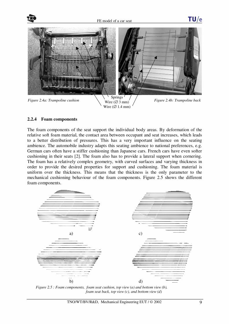
2.2.3 Trampolines
Both the foam components in the seat cushion and seat backare supported by a planar spring system, referred to as‘trampoline cushion’ and ‘trampoline back’. For the seatcushion part, the trampoline is at the front side directlyconnected to the frame. At the rear side for the seat cushionpart and all connections at the trampoline structure in theseat back part, springs are used for the attachment to the frame (figure 2.4). As a result of itsdirect connection to the frame at the front side, the 'trampoline seat' will only allowconsiderable displacements on the back side. Both springs and metal wire structure do allowconsiderable deformations and displacements of the foam, when an occupant takes place inthe seat. The trampoline is nestled among the foam, just beneath the surface. The thin metalwires (∅ 1.4 mm) are connected with a thicker fibre wire with a metal core of ∅ 3 mm.
As can be seen in figure 2.4b, behind the ‘trampoline back’ is a belt, the lumbar support. Thisbelt can be tightened by revolving a button on the door-side of the seat. When tightened, thisbelt will support the foam with the embedded trampoline from behind, reducing its backwardmovement. The occupant will have an extra support in the lumbar region in the lower back.The assumption is made that this lumbar support is in a slack situation and hence does notcontribute to the stiffness.
Figure 2.2: Metal frame of the seat
Figure 2.3: Headrest
9
FE model of a car seat
TNO/WT/BV/R&D, Mechanical Engineering EUT / © 2002
2.2.4 Foam components
The foam components of the seat support the individual body areas. By deformation of therelative soft foam material, the contact area between occupant and seat increases, which leadsto a better distribution of pressures. This has a very important influence on the seatingambience. The automobile industry adapts this seating ambience to national preferences, e.g.German cars often have a stiffer cushioning than Japanese cars. French cars have even softercushioning in their seats [2]. The foam also has to provide a lateral support when cornering.The foam has a relatively complex geometry, with curved surfaces and varying thickness inorder to provide the desired properties for support and cushioning. The foam material isuniform over the thickness. This means that the thickness is the only parameter to themechanical cushioning behaviour of the foam components. Figure 2.5 shows the differentfoam components.
Figure 2.5 : Foam components, foam seat cushion, top view (a) and bottom view (b), foam seat back, top view (c), and bottom view (d)
a) c)
b) d)
Figure 2.4a: Trampoline cushion Figure 2.4b: Trampoline backSprings
Wire (∅ 3 mm)Wire (∅ 1.4 mm)

10
FE model of a car seat
TNO/WT/BV/R&D, Mechanical Engineering EUT / © 2002
3 FE seat model – set-up and assumptions
This chapter describes the set-up of the FE MADYMO model of the seat. First a shortintroduction to MADYMO is given. After this, the model is linked to the theory of the FE-method. For a brief theoretical introduction of the FE-method, the reader is referred toAppendix A. Next, the applied element types and material models of the different seatcomponents are discussed. In order to connect these components, possible connectionmethods are introduced and linked to physical connections. Further, the geometry set-up isdescribed. At last, a summary of the major points of the model set-up and assumptions will begiven.
3.1 MADYMO
MADYMO (MAthematical DYnamic MOdel) is a simulation software package for crashsimulations developed at TNO. Contrary to most simulation software packages, MADYMOhas succeeded in combining MB and FE with two different solvers in one package. In thisway, inside one model, multibody can be used for the simulation of the gross motion ofsystems of bodies connected by kinematical joints, and finite element analysis can be appliedfor the simulation of structural behaviour.
3.2 Link of theory to model – assumptions
Taking advantage of any symmetry in the body or approximating the dimensionality of theproblem can reduce the simulation time of a FE-simulation. Geometrical optimisation, e.g.modelling only a cross section is not possible for the seat model. No advantage was takenfrom the symmetry of the seat, because the occupant will not apply a symmetrical load to theseat. This is due to driving activities as pushing the throttle, the clutch, braking andcentrifugal forces when cornering. Another important factor for seating comfort is the abilityof the user to change seating posture. No single posture is good for more than a few minutes.Another reason why no advantage was taken of symmetry is the future possibility for use ofthe FE-model in crash simulations. It is clear that, e.g. for side impact crash simulations, amodel of a whole seat will be necessary.
3.3 Element types and material models
In the following section the link is made between the functions of the different componentsand elements that have been used in order to describe these components in an accurate way inthe FE-model. Also the used materials are linked to material models available in MADYMO.
3.3.1 Metal frame
Four-node shell elements have been used for the metalframe. A four-node shell element is a two-dimensionalquadrilateral element that connects four nodes and cancarry in-plane loads as well as bending loads. InMADYMO the four-node element type ELEMENT.QUAD4with the properties of a four-node shell elementPROPERTY.SHELL4 has been defined (figure 3.1). Forsimplicity reasons these shell elements have a uniform Figure 3.1: PROPERTY.SHELL4

11
FE model of a car seat
TNO/WT/BV/R&D, Mechanical Engineering EUT / © 2002
thickness of 2.0• 10-3 m. This corresponds to the estimated average thickness of the frame inthe real seat.
While the focus of this study is on comfort, the structure of the metal frame was assumed tobe loaded far below its elastic limit, reducing the required material model from elasto-plasticto an elastic model. Further, a linear behaviour has been assumed since due to the smalldeformations and stresses only a small region of the stress-strain curve will be accessed. Thissmall region has been approximated as linear, which simplifies the material model to linearelastic. At last, the material has been regarded as isotropic, which means that the behaviour inall directions is the same. For an isotropic material, the stiffness matrix is expressed by onlytwo constants, E and ν. In MADYMO, this linear elastic isotropic material had been modelledusing MATERIAL.ISOLIN, with the material parameters of steel • = 7.8• 103 kg/m3, E = 200• 109
Pa and ν = 0.3 [16].
3.3.2 Headrest
The headrest is described as a MB-component, since it has no effect on the comfort behaviourin normal seating behaviour. However, for future utilisation in other simulations, e.g. rear-endcrashes, it might be necessary to convert also this component into FE.
3.3.3 Trampolines
Both foam parts in the seat cushion and back are supported by a planar spring system, astructure of metal wires and springs. They have the same geometric and functionalcharacteristics, and can therefore be modelled in the same way. This paragraph deals with a‘trampoline’ that refers to both planar spring systems.The trampoline has been modelled with truss elements. In MADYMO ELEMENT.LINE2, withthe properties PROPERTY.TRUSS2 have been defined for the wire structure, supporting thefoam at the nodes, but allowing deformations of the solid foam elements between the lineelements just like in the real situation.The material behaviour has been modelled with the linear elastic isotropic material modelMATERIAL.ISOLIN, for the same reason as mentioned for the material of the metal frame. Thetotal mass of the modelled trampoline must be the same as the mass of the planar springsystem in reality, since that is important for the kinematical behaviour.It is preferred to keep the density corresponding to the material used in the seat. Masscorrections can be implemented by varying the cross sectional areas. The used material datafor the steel wires are • = 7.8• 103 kg/m3, E = 200• 109 Pa and ν = 0.3 [16]. The cross sectionalareas (A) have been determined by 2rA ⋅= π , with r the radius of the wires. This leads for the
thin wires of ∅ 1.4 mm and the thicker wire with the metal core of ∅ 3 mm, respectively toA= 1.5• 10-6
m2 and A= 7.1• 10-6 m2.
3.3.4 Springs
The springs have in the model been regarded as elements. They have been modelled withELEMENT.LINE2 elements and PROPERTY.TRUSS2 properties, allowing foam support to deformjust like in the real seat. These truss elements have been described with one-dimensionalKelvin material behaviour MATERIAL.KELVIN1D that is able to describe the characteristicbehaviour of a spring when the damping is set to zero. In absence of any damping thismaterial model behaves the same as a linear elastic material model. With the Kelvin1D model

12
FE model of a car seat
TNO/WT/BV/R&D, Mechanical Engineering EUT / © 2002
12
3
Strain
Stre
ss 1. Linear elastic behaviour2. Elastic buckling / collapse3. Densification
Figure 3.2: PU foam behaviour in compression
Loading-curve
Unloading-curve
• 0
it is possible to describe the stiffness in Newton per meter, which makes it possible to performa test with a steelyard on the existing springs in order to capture the spring stiffness. By now,the stiffness is calculated as 20• 103 N/m [8]. The cross sectional area has been calculated froma radius of 3.1 mm to A = 3.0• 10-5 m2. The material parameters of steel • = 7.8• 103 kg/m3, E =200• 109 Pa and ν = 0.3 [16] have been assigned to the elements. The springs guarantee thepossibility for the foam support to deform.
3.3.5 Foam components
Foams are typically used under compression, but it is very likely that also shear loading willoccur in the foam components of the seat. The behaviour of foams in general can be describedas highly non-linear and strain rate dependent with high energy dissipation characteristics andhysteresis in cyclic loading. For low levels of stress, high levels of strain can be obtained.Low density combined with high energy dissipation capacity make foams attractive forenergy absorbing functions in automotive applications. However, the three-dimensionalmechanical response of foam materials is quite difficult to capture in a mathematical model.At small strains, the mechanical behaviour is close to linear elastic, followed by a large orderof magnitude reduction in slope. Then, there is a long region in which the slope changesgradually. This stagecorresponds to the collapse ofcells. In this stage, the air isgradually pressed out of thefoam. After the cells havecollapsed, the final stage ofdensification is reached inwhich the cells come in contactwith one another causing asharp increase in the stress [12,13]. The polyurethane foam ischaracterised by its stronglynon-linear and compressiblefeature. It is a hyper-elasticcellular elastomer that presentsa significant visco-elasticbehaviour (figure 3.2).
Material data from literature [14] has been used. This data (Appendix B.1) shows the stress-strain response of polyurethane foam (• = 67.7 kg/m3) that is subjected to different strainrates. Because of the complex nature of the foam and because very little is known about theresponse of the polyurethane foam to vibrations and loading in the comfort domain, it can berecommended to perform some experiments to obtain data of the strain rate dependentbehaviour.
Element typeIn order to describe the material behaviour of foam, it is desirable to apply elements that arecapable of dealing with hysteresis. In MADYMO hysteresis can be applied to truss,membrane and solid elements. The first two are flat elements and are therefore not suitable formeshing the three dimensional volume of the foam components. The foam structure has beenmodelled with solid elements, because these are three-dimensional and can carry tensile,compression and shear loads. Two types of solid elements have been considered; the eight-
13
FE model of a car seat
TNO/WT/BV/R&D, Mechanical Engineering EUT / © 2002
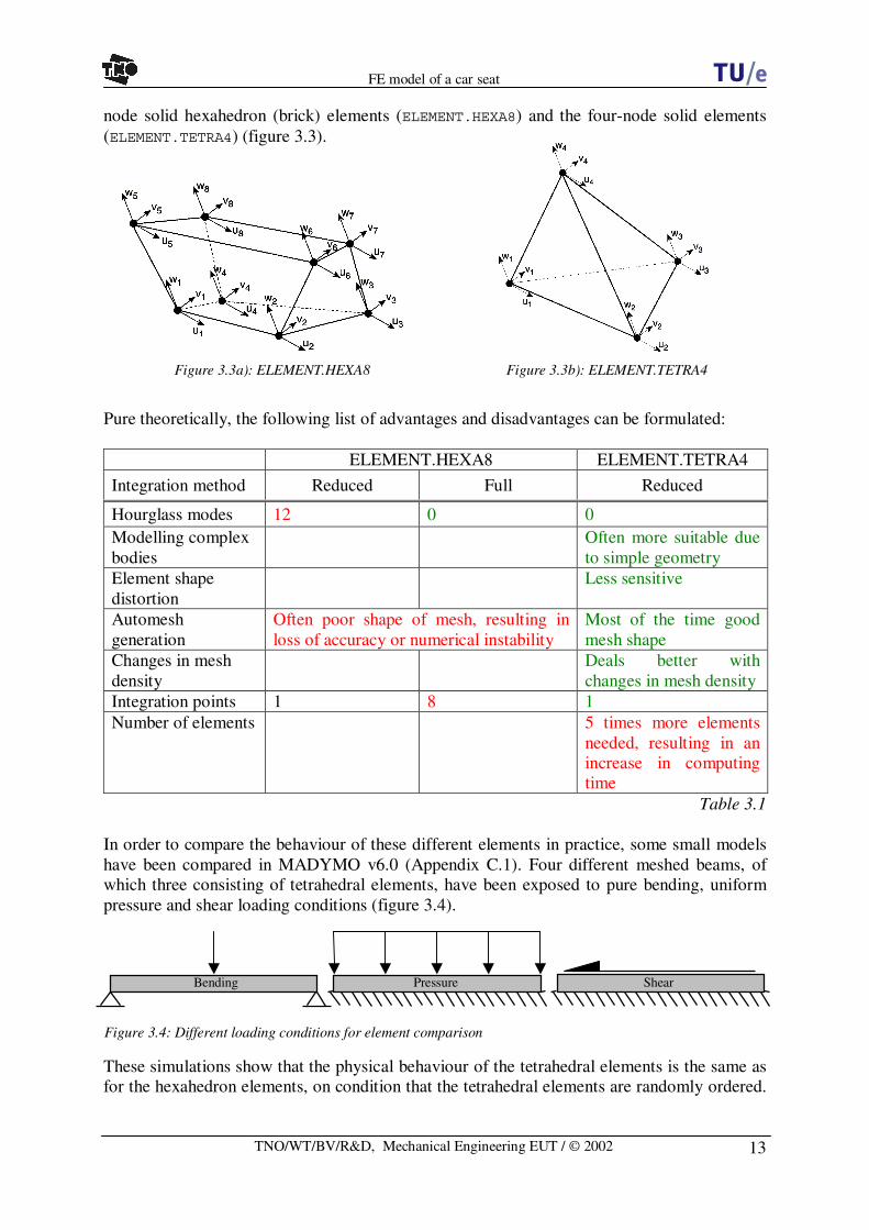
node solid hexahedron (brick) elements (ELEMENT.HEXA8) and the four-node solid elements(ELEMENT.TETRA4) (figure 3.3).
Pure theoretically, the following list of advantages and disadvantages can be formulated:
ELEMENT.HEXA8 ELEMENT.TETRA4
Integration method Reduced Full Reduced
Hourglass modes 12 0 0Modelling complexbodies
Often more suitable dueto simple geometry
Element shapedistortion
Less sensitive
Automeshgeneration
Often poor shape of mesh, resulting inloss of accuracy or numerical instability
Most of the time goodmesh shape
Changes in meshdensity
Deals better withchanges in mesh density
Integration points 1 8 1Number of elements 5 times more elements
needed, resulting in anincrease in computingtime
Table 3.1
In order to compare the behaviour of these different elements in practice, some small modelshave been compared in MADYMO v6.0 (Appendix C.1). Four different meshed beams, ofwhich three consisting of tetrahedral elements, have been exposed to pure bending, uniformpressure and shear loading conditions (figure 3.4).
These simulations show that the physical behaviour of the tetrahedral elements is the same asfor the hexahedron elements, on condition that the tetrahedral elements are randomly ordered.
Figure 3.3a): ELEMENT.HEXA8 Figure 3.3b): ELEMENT.TETRA4
Bending Pressure Shear
Figure 3.4: Different loading conditions for element comparison

14
FE model of a car seat
TNO/WT/BV/R&D, Mechanical Engineering EUT / © 2002
However, the tetrahedral elements behave stiffer. The pressure simulation shows that a largertime step was possible with the tetrahedral elements than with the hexahedron elements.In order to find out which element has the best approximation to the theoretical solution inbending, another simulation has been performed in MADYMO. The material properties ofcarbon steel have been assigned to the already designed beams with the regular hexahedronand random tetrahedral mesh. Their behaviour has been compared to the 'rule of thumb' forbending behaviour of beams (Appendix C.2). These simulations showed that the hexahedronbeam gives a better approximation to the exact solution than the tetrahedral beam. For themost important parts, e.g. the parts that will be loaded when an occupant sits down on theseat, hexa8 elements have been used. At the geometrically complex parts, also tetra4 elementshave been applied because they are more suitable for meshing complex geometries. Thedifference in stiffness between the two elements will not add difficulties, since in thetetramesh part the deformations are not expected to become very large.
Full-integration methods are more accurate but also demand an increased computational timecompared to the reduced integration method. Reduced integration has the disadvantage thatfor some element types hourglassing can take place. This generation of zero-energy modescan occur if, as a result of the reduced integration, not enough deformation parameters inrelation to the nodal degrees of freedom are available. In order to suppress hourglass modes,in MADYMO it is possible to activate an hourglass stabilisation method that suppresses thegeneration of hourglass modes. This hourglass algorithm works with the stiffest part of thecurve of the stress-strain curve and is applied to the whole curve. The elastic buckling orcollapse phase is far less stiff (figure 3.2), and therefore it is not a good approximation toapply the stiffness of the densification phase to the whole curve. The full-integration methodhas to be applied to the hexahedron elements in order to prevent hourglassing.The ADVANCED formulation is selected in MADYMO for both HEXA8 and TETRA4elements, because large deformations are expected in the foam components. This ADVANCEDformulation assures that the time integration is also objective for finite time steps [12]. It usesobjective stress and strain rates, and the time integration is objective for finite increments, andtherefore it prevents that the solution becomes unstable or inaccurate.
Material modelThe material model applied for the foam components is MATERIAL.FOAM. There is no couplingbetween stresses and strains of different principal directions, which means that Poisson effectsare neglected. In the comfort analysis this is a disadvantage, especially because large sheareffects are expected inside the foam components.However, the MATERIAL.FOAM model is the only model that is capable of describing strain ratedependent behaviour. Besides that, it is possible to define different loading and unloadingfunctions for the stress-strain characteristics, and a hysteresis model can be used. By now, theMATERIAL.FOAM model is closest to reality. Problems with shear can be detected by looking atthe element output: large deformations and low stresses would show an unnatural behaviour.The MATERIAL.FOAM model uses a stress-strain curve rather than a material law and isavailable for solid elements only. The stress-strain curve for loading was found in literature[14] (Appendix B.1). With use of a Matlab script the strain rate dependent scaling factors forcharacterising the strain rate effects are determined [15]. Two different formulations, Cowper-Symonds and Johnson-Cook, have been analysed (Appendix B.2). After an evaluation it wasdecided that the Cowper-Symonds strain rate sensitivity scale factor RATE.COWPER would beapplied, since the results differ very little and it is simpler than the Johnson-Cook formulation.The determined values are DRATE = 47.5109 and PRATE = 6.43317.

15
FE model of a car seat
TNO/WT/BV/R&D, Mechanical Engineering EUT / © 2002
In combination with solids, the material model hysteresis is suitable for the characterisation of(low-density) high-hysteresis materials such as polypropylene and polyurethane foams, whichexhibit very high hysteresis and have a very low Poisson’s ratio [12]. Since the hysteresisbehaviour from the foam used is not known, the loading function found in literature has alsobeen applied for the unloading curve. There was no hysteresis model selected and thehysteresis slope was set to zero. It is recommended to perform some experiments to obtaindata for the loading and unloading curves of the foam used in the seat, so that hysteresis,which is very important for describing foam material behaviour correctly, can be added to thematerial model.
3.4 Connection of the different components
In MADYMO several options are available for the connection of the different components.The connections can be divided into FE-FE, MB-FE and MB-MB.
FE - FE MB - FE MB - MBContact 9 9 9
Kinematical joints 9
Equivalent nodes 9
Reference node and supported node list 9
Table 3.2
If contact is defined between two components, contact characteristics have to be calculatedfor each time step. The use of kinematical joints is limited to connections between two MB-bodies. With the method of equivalent nodes, two FE-components can be connected becausethey share the same nodes. This method does not require contact definitions to be calculatedand is therefore computationally efficient. Defining equivalence nodes is only possiblebetween FE-components. Every element has a relation between force and displacement of thenodes. For brick elements this relation is described by translations, but a shell element hasalso rotations contributing to this displacement. For every element, forces are calculated dueto the translations. In a shell element the rotations cause a moment that can be divided inforces in different directions. All separate forces of all elements connected to a certain nodewill result in a displacement of this node. The internal energy of a brick element is based uponthe displacements of the different nodes. Rotations do not contribute to the internal energy ofthis type of element, and therefore brick elements do not supply any resistance againstrotations. In the seat model this behaviour will not take place, since all shells that areconnected to solid foam elements are connected with all four nodes. Table 3.3 summarizes theadvantages and disadvantages from the available connection methods:
Method Advantages DisadvantagesEquivalent nodes No extra compu-
tational costsIncrease in computing time, since the extra contactdefinitions have to be calculated
Contact More realistic
Only active in the case of compression, and in apossible future vibration analysis this might notalways be the case
Kinematical joints Limited to MB - MBTable 3.3

16
FE model of a car seat
TNO/WT/BV/R&D, Mechanical Engineering EUT / © 2002
The connections that have to be specified are looked upon from the perspective what happensif an occupant sits down on the seat. This order is applicable for both seat cushion and seatback:
- First the occupant will make contact to the foam components:- Occupant - Foam (MB - FE)
- The foam will partly deform and partly pass on the load to the componentssupporting the foam; the frame and the trampoline structure:- Foam - Frame (FE - FE)- Foam - Trampoline (FE - FE)
- The trampoline structure is one side attached to the frame directly, and on the otherside springs are attached:- Trampoline - Frame (FE - FE)- Trampoline - Springs (FE - FE)
- The springs are on the other side attached to the frame- Springs - Frame (FE - FE)
Other connections in the model are the connections:- Frame seat cushion - Frame seat back- Frame seat cushion - Inertial space- Frame seat back - Headrest
Occupant - FoamWooden impactors with anthropometrical shapes of a buttock and back have been used in thealready performed experiments. These rigid impactors assured that all the measureddeformations could be contributed to a deformation of the seat. MB-components are non-deformable and therefore used for the impactors, to ensure that also in the model all thedeformations could be contributed to the seat. This connection between the MB-component(impactor) and a FE-component (foam) has been modelled by defining contact definitionsbetween the two parts.
Foam - FrameAt the contact surfaces between the foam and frame components, the same nodes have beenused for defining element of both components, the equivalence nodes. This method ispreferred because it is computationally efficient. However, extra contact definitions might benecessary since contact might for example occur between the foam and the front tube of theseat frame.
Foam - TrampolineThe wires are assumed to be fixed to the foam. This is modelled by defining line elementsbetween nodes of foam elements at the lower side of the foam components. In this way it waspossible to apply the computationally efficient method of equivalence nodes to thisconnection.
Trampoline - FrameEquivalence nodes again define the connection. For the seat cushion part, the trampoline is onthe front side directly connected to the frame, whereas the trampoline structure in the seatback part is fully attached with springs. The line elements from the trampoline that areconnected to the frame at the frame side have been connected to a node that is part of both ashell element of the frame component and a solid element of the foam component. At the

17
FE model of a car seat
TNO/WT/BV/R&D, Mechanical Engineering EUT / © 2002
Figure 3.5: 3D representation of a revolute joint and MB – FE connections
FEj
FEi
MBi
MBj
other side the line element was attached to a node that is also part of a solid foam element andanother line element, also representing the trampoline structure.
Trampoline - Springs and Springs - FrameEquivalence nodes have been defined for both connections. At the back side of the trampolinestructure in the seat cushion part, and for the whole trampoline structure in the seat back part,springs are applied for the connection of the trampolines to the frame. These springs havebeen represented by line elements that are at the side of the trampoline structure connected toa node that is part of both a trampoline wire and also of a solid foam element (see also theconnection Trampoline - Frame). At the other side, this 'spring' line element has beenconnected to a node that also is a node of a shell element of the frame.
Other connections in the model are the physical joints in the seat, e.g. the Frame seat cushion- Inertial space that represents the support of the seat to the car's chassis, and Frame seatcushion - Frame seat back. Rigid bodies with a very low mass have been defined andconnected to each other by kinematical joints. The use of kinematical joints is limited toconnections between two MB-bodies. The rigid bodies have also been connected to thecomponents that are modelled in FE-method. The connection between FE - MB is realised bydefining the initial position and orientation of a reference node on the FE-component to thecoordinate system of a MB-body. A group of nodes that describe the same motion as thereference node are grouped in the so-called support-list.For MB - MB, two MB-bodies can be interconnected to each other with a kinematical joint (arevolute joint (JOINT.REVO). The revolute joint that describes the connection Frame seatcushion - Frame seat back constrains the relative motion of the interconnected bodies to asingle degree of freedom (DOF): only one rotation, figure 3.5).
The Frame seat cushion - Inertial space has been defined by a planar joint: JOINT.PLAN. TheFE-component of the frame supporting the seat cushion has already been connected to a smallrigid body in order to describe the revolute joint between frame seat cushion and frame seatback. This same body has been used to connect the planar joint. A planar joint has only oneDOF, a translation in a plane. This plane has been defined vertically to enable positioning ofthe seat corresponding to the height adjustment and fore-aft adjustment of the seat.
Since the headrest is still described as a MB-component by now, a rigid body with a low massalso has to be connected to the frame seat back. This MB-body can be used to define a bracketjoint JOINT.BRAC for the connection Frame seat back - Headrest. A bracket joint is a joint

18
FE model of a car seat
TNO/WT/BV/R&D, Mechanical Engineering EUT / © 2002
that has no DOFs. If, for future utilisation in other simulations the headrest also is convertedinto FE, the method of equivalent nodes will also be applicable for this connection.
3.5 Geometry
The program used for meshing and creating the geometry is introduced first, followed by adiscussion about the geometric assumptions. Further, the total geometry is presented inparagraph 3.5.2.
3.5.1 Hypermesh
Hypermesh (v4.0) is a software package from Altair, which has been used to generate themesh of the seat. The outer dimensions were already determined by measurements with theFARO Coordinate Measuring System. Data points for the geometry of the seat were measuredevery 2 centimetres while tracking over the outer surface of the seat. The measuredcoordinates have been translated into Hypermesh and used for the generation of the outergeometry of the seat. With this outer geometry as basis, the geometry of the other componentshas been determined by accurately measuring the dimensions of the components.
3.5.2 Geometric assumptions
Several modifications were necessary to the outer geometry measured with the FAROCoordinate Measuring System. This can partly be attributed to the fact that the outerdimensions of the MB-model have beenmeasured with an intact seat. The fabric aroundthe foam on the one hand compresses thefoam, but on the other hand contributes to anextra thickness. In the model the edges andsurfaces on the sides of the foam part havebeen adjusted by moving the measuredcoordinates slightly outwards, resulting in a bitlarger foam component as measured by FARO.The back sides of the foam components havebeen subdivided in mostly straight surfaces,making it easier to mesh. Small protrudingfoam parts not contributing to the stiffnesshave not been modelled. This simplifies thegeometry and results in a higher quality mesh.
Also the frame had some adaptations, e.g. atthe large tube at the back side (figure 3.6). Theradius has been adapted in order to make iteasier to define equivalent nodes. The radius atthe side where the springs are connected hasthe same radius as the real tube (∅ 40 mm). Inthis way the position of the springs thatconnect the trampoline to the tube has beenmodelled accurately. The bend in the rear tubehas not been modelled (figure 3.7). Forsimplification, the region that would make
Figure 3.6: Frame tube at back side of cushion part
Figure 3.7: Bend in rear tube frame seat cushion

19
FE model of a car seat
TNO/WT/BV/R&D, Mechanical Engineering EUT / © 2002
contact with this bend had not been modelled in the foam component since it had beenassumed that it was not a supporting part. Besides that, the frame can be regarded rigidcompared to the foam components. The modelled frame only consists of the rough shape ofthe frame. All additional parts are left out of the model, as well the weight-saving holes. Themajor goal of the modelled frame was to achieve an accurate description of the contactsurfaces between foam and frame.
3.5.3 Mesh density
MADYMO applies the central difference method since this is most efficient for short durationcrash analysis, in which explicit integration methods are preferred. Explicit methods areconditionally stable and therefore put limitations on the possible time step. Due to the finespatial discretisation required, a much smaller time step is needed for FE-models than forMB-models. In the central difference method, the displacements and velocities are calculatedfrom quantities at previous points only. This is called an explicit time integration method. Thetime step must be small enough to ensure that the solution does not grow without bound. Inthe relatively very long simulations in a comfort analysis, the central difference method is notthe most desirable method. The smallest element size determines the time step: a sound wavemay not cross the element during one time step. For undamped linear systems, the time step islimited by: ω2≤∆t , where ω is the maximum eigenfrequency appearing in the mesh. This is
the 1-D Courant stability condition: cLt ≤∆ , where c is the dilatational wave speed and L isthe characteristic length of the element. The speed of sound for linear material is a function of
the elasticity and density of the material: ρE
c = , where E is the Young’s modulus and ρ
the density of the material. The critical time step for stability depends on the size of thesmallest element as well as the elasticity and density of the material modelled. For non-linearsystems, a similar stability criterion cannot be derived. However, for most practical non-linearproblems an extra 10 % reduction on the Courant criterion is sufficient [12]. It must be notedthat the 1-D Courant criterion is only used as estimation for the time step in the model, sincethe mesh consists of 3-D solids and 2-D shells.
The hexa8 elements in the foam parts had been modelled as cubes with an element size of 10mm. Using this element size creates a square node pattern with nodes separated 10 mm fromeach other, which is the same as the pressure measurement points pattern that will be used infuture tests with real occupants. Because equivalent nodes are used for most connections, theelement size for the other components, e.g. the shell elements of the frame, is determined bythe element size of the foam component. With an element size of 10 mm the time step for thisnon-linear model is determined to be:
][1078.110200
108.710109.09.0 6
9
33 s
ELt −− ⋅=
⋅⋅⋅⋅⋅=
⋅⋅=∆ ρ
, resulting in an order 10-6.
However, it is likely that there are also some smaller elements in the mesh, e.g. near the edgesalso different sized elements were inevitable. These elements would require even a smallertime step.
20
FE model of a car seat
TNO/WT/BV/R&D, Mechanical Engineering EUT / © 2002
3.5.4 Results
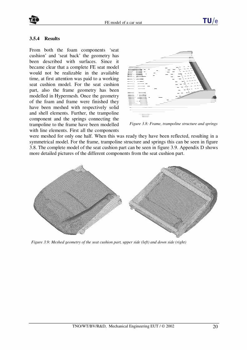
From both the foam components ‘seatcushion’ and ‘seat back’ the geometry hasbeen described with surfaces. Since itbecame clear that a complete FE seat modelwould not be realizable in the availabletime, at first attention was paid to a workingseat cushion model. For the seat cushionpart, also the frame geometry has beenmodelled in Hypermesh. Once the geometryof the foam and frame were finished theyhave been meshed with respectively solidand shell elements. Further, the trampolinecomponent and the springs connecting thetrampoline to the frame have been modelledwith line elements. First all the componentswere meshed for only one half. When this was ready they have been reflected, resulting in asymmetrical model. For the frame, trampoline structure and springs this can be seen in figure3.8. The complete model of the seat cushion part can be seen in figure 3.9. Appendix D showsmore detailed pictures of the different components from the seat cushion part.
Figure 3.9: Meshed geometry of the seat cushion part, upper side (left) and down side (right)
Figure 3.8: Frame, trampoline structure and springs

21
FE model of a car seat
TNO/WT/BV/R&D, Mechanical Engineering EUT / © 2002
3.6 Summary of the model set-up and assumptions
ELEMENT TYPES AND MATERIAL MODELSComponent General MADYMO
Shell elements,reduced integration
ELEMENT.QUAD4, PROPERTY.SHELL4, four-node shellelements with thickness 2.0• 10-3 m.
Frame
Elasto-plasticbehaviour is verycommon fordescribing metalmaterial behaviour
Focus on comfort, so assumed that no plasticbehaviour occurs → Linear elastic isotropic material:MATERIAL.ISOLIN.
• = 7.8• 103 kg/m3, E = 200• 109 Pa, and ν = 0.3ELEMENT.HEXA8 (full integration)PROPERTY.SOLID8, FULL_INT = ON ADV_STRAIN = ON
Solid elements
ELEMENT.TETRA4 (reduced integration)PROPERTY.SOLID4, ADV_STRAIN = ON
Foam materialproperties, withstrain ratedependency
MATERIAL.FOAM, • = 67.7 kg/m3
RATE.COWPER: DRATE = 47.5109 PRATE = 6.43317
Foam
CHARACTERISTIC.LOAD
Same loading and unloading functions [14]. Hysteresis slope = 0.0 Hysteresis model = noneELEMENT.LINE2, PROPERTY.TRUSS2
Thin wires (∅ 1.4 mm): A = 1.5• 10-6 m
2
Thick wire (∅ 3 mm): A = 7.1• 10-6 m2
Trampoline
MATERIAL.ISOLIN: Linear elastic isotropic material • = 7.8• 103 kg/m3, E = 200• 109 Pa, and ν = 0.3ELEMENT.LINE2, PROPERTY.TRUSS2, A = 3.0• 10-5 m2SpringsOne-dimensional Kelvin material behaviour:MATERIAL.KELVIN1D
Stiffness = 20• 103 N/m Damping coefficient = 0.0
CONNECTIONSType of connection: Applied to:
Contact definitions Occupant - FoamEquivalent nodes Foam - Frame
Foam - TrampolineTrampoline - FrameTrampoline - SpringsSprings - FrameFrame seat cushion – Frame seat back JOINT.REVO
Frame seat cushion - Inertial space JOINT.PLANKinematical constraints
Frame seat back - Headrest JOINT.BRAC

22
FE model of a car seat
TNO/WT/BV/R&D, Mechanical Engineering EUT / © 2002
4 Validation of the FE seat model
The seat cushion and the seat back can be validated separately. Due to a lack of time, only thecushion part of the FE seat model has been finished during this project. For the validation ofthis part, the FE-mesh of the foam component, the frame seat cushion and the trampoline andsprings, are implemented into a MADYMO v6.0 model that simulates already performed testswith an anthropometrical shape (wooden buttocks).
4.1 Performed tests
Since comfort analysis deals with (quasi-)static conditions, the seat was loaded with lowvelocity (v = 0.09 cm/s) and it was decided not to measure damping; probably there will be novelocity-dependency of the seat foam during low severity loading. However, hysteresis wasincluded by measuring the loading and unloading stiffness functions. The seat was tested witha rigid humanlike form: all deformations can be contributed to the seat. The seat was loadedup to a specified force that is based on an assumption what realistic is for masses andacceleration loading on e.g. seat cushion and seat back. In the experiment with the woodenbuttocks (figure 4.1) a maximum force of 1000 N was applied. Figure 4.2 shows theexperimental set-up of these tests. The impactor was positioned such that there was initiallyno contact and it was tried to reach a contact area as large as possible during the tests.
Figure 4.2: Experiments with the wooden buttocks impactorFigure 4.1: Wooden buttocks impactor

23
FE model of a car seat
TNO/WT/BV/R&D, Mechanical Engineering EUT / © 2002
4.2 Simulation
For the simulation, a MB-component of theimpactor has been used (figure 4.4). Thisimpactor was available from earlier simulationswith a MB-model of car seat. The geometry ofthe wooden impactor used in the experimentshas been measured with the FARO CoordinateMeasuring System and a MB-model wascreated in Hypermesh and converted toMADYMO. A MB-component cannot deform,which implies that just like in the realexperiments, all deformations can becontributed to the seat model, and hence a goodvalidation from the seat model can beperformed. The impactor was positioned inaccordance to the performed experiments:there was initially no contact and it was tried toreach a contact area as large as possible duringthe simulation.
The strain rate sensitivity was removed from the foam material model, which resulted in anenormous reduction in simulation time, since this made it possible to scale-up the model afactor 1.0• 105 compared to the real tests. Because the FE-model of the seat cushion showedinstability, several adjustments have been applied to the model. Several critical elements havebeen removed from the model, since they kept the model from running or required a verysmall time step. Further, the hourglassing stabilisation method available in MADYMO hasbeen activated for the solid hexahedral foam elements and the shell frame elements. The FE-FE contact has been defined as a penalty based contact. Because the model was instable, themaximum force parameter has been set to 0.001, which puts a limitation on the contact force.The time step has been set variable, which means that after each cycle the analysis time stepcould be adapted by MADYMO. After all these adaptations the final time step of thesimulation was an order 10-7 [s].
Figure 4.5 shows the simulation withthe buttocks impactor. Although therewas no time to validate the performedsimulations with the data from the tests,the simulations show that it is possibleto have a representation of the pressuredistributions of a representative buttockand to virtually model and test seatcomponents under dynamic loading.However, it must be mentioned that thecontact characteristics needimprovement because of all theadaptations that have been made tomake the model running. Figure 4.5: Simulation with the seat cushion part
Figure 4.4: MB-model wooden buttocks impactor

24
FE model of a car seat
TNO/WT/BV/R&D, Mechanical Engineering EUT / © 2002
5 Conclusion and Recommendations
5.1 Conclusion
By disassembling the seat, it was possible to explore the geometries of the differentcomponents and to determine the materials and mechanical properties. A survey to theelement types, material models and assumptions for the different components of the seatmodel has been performed. Also methods for the connections between the differentcomponents have been evaluated. The geometries of both foam components ‘seat cushion’and ‘seat back’ have been completely digitalized as surfaces. Because it became clear that acomplete seat model would not be realisable in the available time, the first focus has been oncreating a working seat cushion part model. For this, it was necessary to correctly digitalizethe geometries of the foam, and frame seat cushion. After that, the foam component has beenmeshed with solid elements and the frame with shell elements. Both trampoline and springsconsist of line elements. All seat cushion components have been implemented into aMADYMO v6.0 model that simulates already performed tests with an anthropometrical shapeof a wooden buttock. Although there was no time to validate the performed simulations to thedata from the earlier performed tests, these simulations showed that it is possible to have arepresentation of the pressure distributions of a representative buttock and to virtually modeland test seat components under dynamic loading. The model will have to be improved atseveral points, e.g. the material model of the polyurethane foam and a validation to earlierperformed tests. However, the achieved results prove that it is a promising model that has thepotential to result in an objective assessment tool to support virtual testing of automotiveseating comfort during the design phase of new comfortable seats.
5.2 Recommendations
The major recommendation is to finish and validate the model. The geometries of both foamcomponents ‘seat cushion’ and ‘seat back’ have been completely created as surfaces. Thegeometry of the foam component from the back has been finished with a 2D mesh, but it stillhas to be meshed with solids. Also, the geometry of the frame seat back has to be modelledand meshed. The solid mesh of the seat cushion needs enhancement in the means of adjustingcritical elements in the mesh. After that the contact characteristics have to be improved. Oncethe mesh and contact are improved and the model validated, all components are ready for afull comfort analysis of the seat. For possible future use in crash situations, it might benecessary to create a FE-component of the headrest.
Experiments are desired for characterisation of the loading and unloading curve of thepolyurethane foam and the strain rate dependent behaviour. The mechanical response of mostmaterials depends on the applied strain rate. In particular certain foams and biologicalmaterials exhibit a typical visco-elastic behaviour; i.e. the resistance against sudden changesof shape is relatively high compared to the quasistatic resistance against deformation. Furtherresearch will have to make clear if this is also the case for the relatively low velocitiesassociated with the comfort-domain. Appendix E contains a recommendation for experiments.
Once the FE-model has been finished, some experiments will have to be performed with thewooden buttocks in which pressures are measured. At last, pressure measurements will haveto be performed with real humans.

25
FE model of a car seat
TNO/WT/BV/R&D, Mechanical Engineering EUT / © 2002
References
[1] J.Lee, T.Grohs, Evaluation of Objective Measurement Techniques for Automotive SeatComfort, Lear Seating Co., SAE 950142, International Congress and ExpositionDetroit, Michigan, March 1995
[2] K. Kamijo, H.Tsujimura, H. Obara, M. Katsumata, Evaluation of seating comfort,SAE 820761, SAE Conference, 1982
[3] A. Milivojevich, R. Stanciu, A. Russ, G. Blair, J. van Heumen, Investigatingpsychometric and body pressure distribution responses to automotive seating comfort,SAE 2000-01-0626, SAE Conference, 2000
[4] K. Uenishi, K. Fujihashi, H. Imai, A seat ride evaluation method for transientvibrations, SAE 2000-01-0641, SAE Conference, 2000
[5] H. Inagaki, T. Taguchi, E. Yasuda, Y. Iizuka, Evaluation of riding comfort: from theviewpoint of interaction of human body and seat for static, dynamic, long time driving,SAE 2000-02-0643, SAE Conference, 2000
[6] L. Zhao, Q. Xia, X. Wu, Study of sitting comfort of automotive seats, SAE 945243,SAE Conference, 1994
[7] S.Park, C.Kim, The evaluation of seating comfort by objective measurements, SAE970595, SAE Conference, 1997
[8] H.Bauer, A.Cypra, A.Beer, Automotive Handbook 4th edition, Robert Bosch GmbH,Stuttgart, Germany, 1996
[9] J.Pywell, Automotive Seat Design Affecting Comfort and Safety, General MotorsCorp., SAE 930108, International Congress and Exposition Detroit, Michigan, March1993
[10] U.Seiffert, Fahrzeugsicherheit: Personenwagen, VDI-Verlag, ISBN 3-18-401264-6,Düsseldorf, Germany, 1992
[11] M.J.Fagan, Finite Element Analysis – theory and practice, Addison Wesley LongmanLimited, Harlow, England, ISBN 0-582-02247-9, 1992
[12] TNO Automotive, MADYMO v6.0 Theory Manual, Delft, The Netherlands 2001
[13] M.Pajon, M.Bakacha, D.Pignede, P.van Effenterre, Modeling of P.U. Foam Behavior– Applications in the Field of Automotive Seats, Bertrand Faure Equipments S.A.,SAE 960513, International Congress and Exposition Detroit, Michigan, February 1996
[14] J. Zhang, N. Kikuchi, V. Li, A. Yee, G. Nusholtz - Constitutive Modeling ofPolymeric Foam Material Subjected to Dynamic Crash Loading, International Journalof Impact Engineering, Volume 21, Number 5, ISSN 0734-743x, 1998
26
FE model of a car seat
TNO/WT/BV/R&D, Mechanical Engineering EUT / © 2002
[15] W. Wang, Parameter Identification For Phenomenological Foam Models, TNOAutomotive, TNO report 00.OR.BV.034.1/WW, 2000
[16] P.H.H. Leijendeckers, J.B. Fortuin, F. van Herwijnen, H. Leegwater, Poly-technischZakboekje – 48e druk, Koninklijke PBNA b.v., ISBN 90-6228-266-0, Arnhem, 1997
[17] R.T. Fenner, Mechanics Of Solids, 1st edition, Blackwell Scientific Publications, ISBN0-632-02018-0, Oxford, 1989
[18] TNO Automotive, MADYMO v6.0 Reference Manual, Delft, The Netherlands 2001
[19] P.Schreurs, W.Brekelmans, Materiaalmodellen, dictaatnr. 004768, TechnischeUniversiteit Eindhoven, 1997
[20] A.K. van der Vegt, Polymeren – van keten tot kunststof, Delftse Universitaire Pers,ISBN 90-407-1283-2, 1991
[21] J.Lee, P. Ferraiuolo, Seat Comfort, Ford Motor Co., SAE 930105, InternationalCongress and Exposition Detroit, Michigan, March 1993
[22] E.Berger, B.Gilmore, Seat Dynamic Parameters for Ride Quality, The PennsylvaniaState Univ., SAE 930115, International Congress and Exposition Detroit, Michigan,March 1993
[23] W.Beitz, K-H.Grote, Taschenbuch für den Maschinenbau / Dubbel, 19. Auflage,ISBN 3-540-62467-8, Springer Verlag, Germany, 1997
[24] B.Elton, R.Hubbard, Using Anthropometric Data to Improve Seat Back Comfort inCurrent and Future Passenger Car Seats, Creative Design Studios, SAE 930111,International Congress and Exposition Detroit, Michigan, March 1993
[25] R.Marshall, P.Altamore, D.Muller, D.Pruitt, Modeling Energy Absorption InCommercial Airline Seating With MADYMO Dynamic Simulation, 1994 SAFEConference, Atlanta GE, November 1999
[26] R.Marshall, P.Altamore, Dynamic Analysis of Crew Seats and Cockpit Interiors, SAE2000-01-1674, TNO-MADYMO North America, 2000

27
FE model of a car seat
TNO/WT/BV/R&D, Mechanical Engineering EUT / © 2002
Appendix A: FE Method - Theoretical Introduction
The Finite Element (FE) method can be used to calculate static, dynamic and acousticcharacteristics of components and complete bodies. In finite element analysis, a structure isbroken down into simple structural elements (beams, shells, solid elements, etc.), of which theelastic behaviour is known and can be easily defined. These elements are assumed to beinterconnected at a discrete number of points: the nodes. In the displacement-based finiteelement formulation, which is applied in practically all major finite element softwarepackages, the motion of points within each finite element is defined as a function of themotion of the nodes. The state of stress follows from the deformations and the constitutiveproperties of the material modelled. In the absence of thermo-mechanical effects, the basicequations are:
- the momentum equation,- the constitutive equation (the material behaviour: a relationship between stresses and
strains), and- the strain-displacement relationship (deformation as a function of displacements).
For given initial and boundary conditions, the system response is embedded in theseequations. However, an analytic solution of the resulting partial differential equationssatisfying the initial and boundary conditions exists only for very simple cases, and thus anumerical procedure must generally be used.
Care must be taken in the planning and preparation of the problem, because considerablesavings in time and effort, in both model and analysis, can be achieved by careful modeldesign. In particular, economies can usually be made by approximating the dimensionality ofthe problem, and by taking advantage of any symmetry in the body.
Basic element shapes and their behaviourBasic elements are forexample membraneelements, shell elements andsolid elements (figure A.1).In membrane elements, onlyin-plane loads arerepresented, with no bendingstiffness normal to the plane.Shell elements are a veryspecial category since theyare essentially two-dimensional in nature, butare developed so that theycan be used to model curvedsurfaces. For stress analysis problems, shell elements are curved plate elements that includeboth bending and membrane or stretching effects. So, in contrast to membrane elements, shellelements can also deal with loads that are not in-plane. For example the four-node shellelement ELEMENT.QUAD4 used in MADYMO can carry in-plane loads as well as bendingloads. Solid elements are three dimensional elements that can carry tensile, compression and
Shell-element Solid-element
Figure A.1: Examples of commonly used element types

28
FE model of a car seat
TNO/WT/BV/R&D, Mechanical Engineering EUT / © 2002
shear loads. The stress components for a solid element are in MADYMO defined with respectto the inertial coordinate system.
The sides of elements can be straight or curved. For straight elements, the basic finite elementmethod works by approximating the variation of a field variable through each element with aknown (interpolation) function, usually a polynomial. However, for distorted and therefore'curved' elements, the time and complexity of the solution are increased significantly due tothe fact that it is also necessary to describe the geometry of the chosen element with apolynomial. If the geometric interpolation function and the displacement interpolationfunction are of the same order, the two functions prove to be similar to each other, whichsimplifies their application significantly.
Choice of element typeAlthough most commercial finite element packages have a lot of different elements, whichcan easily mount up till even more than a hundred different elements, the selection of whichelement to use is not as difficult as it might appear in the beginning. Firstly, the type ofproblem to be analysed (i.e. stress), precludes a large number of elements; secondly, thechosen dimensionality of the model restricts the range further.
Size and number of elements used in modelThe size and number of elements in a finite element model are clearly inversely related. Asthe number of elements increases, the size of each element must decrease, and consequentlythe accuracy of the model generally rises, since the finite element solution graduallyapproaches the true value. As the number of elements approaches infinity, the model’sprediction will approach the exact solution. The gain in accuracy has to be valuable enough topay the extra cost of increased calculation time by an enlarged model size caused by thebigger amount of elements. In fact, it is usual to have many different sized elements in amodel. High mesh density (i.e. small elements) will be applied in areas with an expected rapidchange in the unknown variable. Before meshing the finite element model, the engineershould predict the path of the stress distribution in order to position the elements and decidethe mesh density applied to the different areas of the model.
Following this, the location of the nodes is consideredThe location of the elements and therefore of the nodes must, except for the adequaterepresentation of the variable distribution, also reflect changes in material properties,geometry, constraint conditions and applied loads. For example, an element cannot comprisetwo different materials, and therefore a line (or area) of nodes will always be required at theinterface of different materials. Or, if a distributed load is present, then nodes must define thestart and finish positions of the load. Attention must be paid that all the nodes are connectedin adjacent elements. If this is not the fact, it implies that there is a hole in the material, andthe results from such a finite element model would show discontinuity at these points.

29
FE model of a car seat
TNO/WT/BV/R&D, Mechanical Engineering EUT / © 2002
Appendix B: Foam material
B.1 Stress-strain response under uniaxial compression for different strain rates
The material data available in literature [14] shows the stress-strain response of polyurethanefoam (• = 67.7 kg/m3) under uniaxial compression for different strain rates.
Quasi-static Dynamic8.00• 10-5 [m/s] 4.00• 10-3 [m/s] 2.29• 10-1 [m/s]
Eng. Strain[-]
Stress [MPa] Eng. Strain[-]
Stress [MPa] Eng. Strain[-]
Stress [MPa]
0.00000 0.00000 0.00000 0.00000 0.00000 0.000000.04213 0.00615 0.05170 0.00923 0.04596 0.008620.12830 0.01108 0.13596 0.01354 0.12638 0.015080.21638 0.01292 0.22021 0.01538 0.22596 0.017540.30255 0.01446 0.30255 0.01662 0.28723 0.018770.38681 0.01600 0.38489 0.01846 0.36766 0.020920.47489 0.01785 0.46723 0.02138 0.45000 0.025080.56298 0.02231 0.55149 0.02831 0.53234 0.029690.65106 0.03154 0.63383 0.03708 0.61277 0.041230.73915 0.04677 0.71809 0.05277 0.69511 0.055230.83106 0.07692 0.80234 0.08200 0.77936 0.094460.88085 0.12000 0.85021 0.12000 0.81574 0.12000
0 0.1 0.2 0.3 0.4 0.5 0.6 0.7 0.8 0.90
0.02
0.04
0.06
0.08
0.1
0.12PU Foam Stress-Strain Response (Uniaxial Compression)
Engineering Strain [-]
Stre
ss [
MP
a]
8.00E-5 [m/s] "Quasi-static"4.00E-3 [m/s] "Dynamic 1" 2.29E-1 [m/s] "Dynamic 2"

30
FE model of a car seat
TNO/WT/BV/R&D, Mechanical Engineering EUT / © 2002
In MADYMO, the reference stress curve for the quasi-static situation must be defined interms of nominal stresses versus logarithmic strains. For this reason the engineering strain isconverted into logarithmic strain:
The elongation factor λ is defined as 0l
l=λ , and this leads for the engineering strain to:
10
0
0
−=−=∆= λεl
ll
l
leng , and therefore: 1+= engελ . The logarithmic strain has therefore the
following relation to the engineering strain: ( ) ( )1lnlnln +== engελε .
Quasi-static Dynamic8.00• 10-5 [m/s] 4.00• 10-3 [m/s] 2.29• 10-1 [m/s]
Log. Strain[-]
Stress [MPa] Log. Strain[-]
Stress [MPa] Log. Strain[-]
Stress [MPa]
0.00000 0.00000 0.00000 0.00000 0.00000 0.000000.04127 0.00615 0.05041 0.00923 0.04494 0.008620.12071 0.01108 0.12748 0.01354 0.11901 0.015080.19588 0.01292 0.19902 0.01538 0.20372 0.017540.26432 0.01446 0.26432 0.01662 0.25249 0.018770.32701 0.01600 0.32562 0.01846 0.31310 0.020920.38858 0.01785 0.38338 0.02138 0.37156 0.025080.44659 0.02231 0.43922 0.02831 0.42680 0.029690.50142 0.03154 0.49093 0.03708 0.47795 0.041230.55340 0.04677 0.54121 0.05277 0.52775 0.055230.60490 0.07692 0.58909 0.08200 0.57625 0.094460.63172 0.12000 0.61530 0.12000 0.59649 0.12000
0 0.1 0.2 0.3 0.4 0.5 0.6 0.70
0.02
0.04
0.06
0.08
0.1
0.12PU Foam Stress-Strain Response (Uniaxial Compression)
Logarithmic Strain [-]
Stre
ss [
MP
a]
8.00E-5 [m/s] "Quasi-static"4.00E-3 [m/s] "Dynamic 1" 2.29E-1 [m/s] "Dynamic 2"

31
FE model of a car seat
TNO/WT/BV/R&D, Mechanical Engineering EUT / © 2002
B.2 Determination of strain rate dependent scaling factors
The material from Appendix B.1 shows the stress-strain response of polyurethane foam underuniaxial compression for different strain rates. The stress-strain relationship is mathematicallydefined by:
rg σεσ
=
⋅
formula B.1
where g is the scaling factor that depends on the effective strain rate, and rσ is a userspecified reference stress curve. The effective strain in the scaling factor is defined as:
( )Ttr εεε ⋅= formula B.2
where tr stands for the trace of the matrix. Two analytical laws are available for scaling theuser-defined stress-strain curve, the Cowper-Symonds and the Johnson-Cook formulations:
Cowper-Symonds:
2
1
1
1
c
nn
cg
+=
⋅⋅ εε formula B.3
Johnson-Cook:
+=
⋅⋅
1,maxln11
2c
cgn
nεε formula B.4
With use of a Matlab script the strain rate dependent scaling factors for both formulationsCowper-Symonds and Johnson-Cook have been determined. This Matlab script first loads thematerial data for the quasi-static stress-strain curve, followed by the two dynamic curves.With use of these data, the 'DRATE' (c1, the strain rate for which the loading/unloading isgiven) and the 'PRATE' (c2, the exponential amplification constant) are determined. After that,the fit curves are plotted (figure B.1). Both scaling factors show a good fit to the real curve. It
was decided that the Cowper-Symonds strain rate sensitivity scale factor would be applied,since the results differ very little and it is simpler than the Johnson-Cook formulation. Thedetermined values are DRATE = 47.5109 and PRATE = 6.43317.
Figure B.1a: Fit curve for Cowper-Symonds Figure B.1b: Fit curve for Johnson-Cook
0 0.1 0.2 0.3 0.4 0.5 0.6 0.7 0.8 0.90
0.02
0.04
0.06
0.08
0.1
0.12
strain [-]
stre
ss [
Mpa
]
Fitcurve for Cowper-Symonds formulation
data: v = 4.00E-3 [m/s]fit: v = 4.00E-3 [m/s] data: v = 2.29E-1 [m/s]fit: v = 2.29E-1 [m/s]
0 0.1 0.2 0.3 0.4 0.5 0.6 0.7 0.8 0.90
0.02
0.04
0.06
0.08
0.1
0.12
strain [-]
stre
ss [
Mpa
]
Fitcurve for Johnson-Cook formulation
data: v = 4.00E-3 [m/s]fit: v = 4.00E-3 [m/s] data: v = 2.29E-1 [m/s]fit: v = 2.29E-1 [m/s]

32
FE model of a car seat
TNO/WT/BV/R&D, Mechanical Engineering EUT / © 2002
Appendix C: Solid element comparison for foam mesh
C.1 Comparison by basic loading conditions
In order to compare the behaviour of the hexahedron and tetrahedral elements, respectivelyELEMENT.HEXA8 and ELEMENT.TETRA4 in MADYMO, three models have been made inMADYMO v6.0. In total four different meshed beams have been compared in three differentbasic loading conditions: pure bending, uniform pressure and shear.
The beams are meshed in different ways, resulting in different meshes (figure C.1):1 Hexa8-beam,2 Tetraregular-beam,3 Hexa-to-tetra-beam,4 Tetramesh-beam.
1. The Hexa8-beam consists of avery regular mesh of 'brick'elements.
2. The Tetraregular-beam consistsof a very regular mesh oftetrahedral elements.
3. The Hexa-to-tetra-beam alsoconsists of a regular mesh. InHypermesh the elements of theHexa8-beam are split intotetrahedral elements. Unless themesh looks very much like theone in the Tetraregular-beam, ithas some vertical layers ofelements pointing in a differentdirection.
4. The Tetramesh beam is madeby the 'tetramesh' function ofHypermesh. This results in a veryrandom mesh of tetrahedralelements.
The tables on the following pagesummarise the data applied for thethree different situations; bending,pressure and shear loading.
2
4
1
Figure C.1: Different meshed beams

33
FE model of a car seat
TNO/WT/BV/R&D, Mechanical Engineering EUT / © 2002
Bending Prescribed displacementTotal simulation time (s) 2.5Analysis time step (s) 1• 10-4
Integration method EulerAnalysis type DynamicOutput time step (s) 1• 10-1
Boundary conditions: Outer nodes on the lowerplane are supported. All DOFare locked for these nodes.
A displacement is applied tothe mid nodes on the upperplane.
Pressure Prescribed displacementTotal simulation time (s) 2.0Analysis time step (s) 1• 10-5
Integration method EulerAnalysis type DynamicOutput time step (s) 1• 10-1
Boundary conditions: All nodes on the lower planeare supported. All DOF arelocked for these nodes.
A displacement is applied toall the nodes on the upperplane.
Shear Prescribed displacementTotal simulation time (s) 2.5Analysis time step (s) 1• 10-4
Integration method EulerAnalysis type DynamicOutput time step (s) 1• 10-1
Boundary conditions: All nodes on the lower planeare supported. All DOF arelocked for these nodes.
A displacement is applied toall the nodes on the upperplane, and their DOF in z-direction is locked.
0 0.5 1 1.5 2 2.5
-0.02
-0.015
-0.01
-0.005
0Applied Displacements
Time [s]
Dis
plac
emen
t [m
]
Bending PressureShear

34
FE model of a car seat
TNO/WT/BV/R&D, Mechanical Engineering EUT / © 2002
As can be seen in the graph of the applied displacements, the maximum displacement is heldconstant for a small period. This is done in order to be sure that the material is in a state ofequilibrium, no elements are moving anymore. The simulations show that the two regulartetrahedral beams 'Tetraregular & Hexa-to-tetra', do not behave realistic. As can be seen infigure C.2, under bending conditions, the right beam (Tetraregular) has a direction sensibility;it moves lateral when lookingupon in longitudinal direction.The left beam (Tetramesh) alsoconsists of tetrahedral elements,but does not show this behaviour.The reason for this is, that the netcumulative effect of the directionsensibility of the differentelements in different directionshas almost no effect over all theelements in the random mesh.The shear simulation also showsthis effect of direction sensibility.For the Hexa-to-tetra-beam, thiseffect was also observed, but dueto different geometricalorientation of the regular meshed elements in some vertical layers, it was not as clearlyperceptible as by the Tetraregular-beam. Due to this direction sensible behaviour, a regularmesh of tetrahedral elements is not desirable.
During the pressure simulation, it became clear that a simulation with an analysis time step of1• 10-4 s resulted in an unstable model for the beam meshed with hexahedron elements. Inorder to have a stable simulation the time step is set to 1• 10-5 s. The factor 10 bigger time stepthat would have been possible with the tetrahedral elements can be mentioned as an advantagecompared to the hexahedron elements. It shows that the tetrahedral elements are more stablein this simulation.
Figure C.3: Von Mises stresses at the maximum state of uniform pressure (left) and shear loading (right)
1
2
3
4
Tetramesh-beam Tetraregular-beam
Figure C.2: Longitudinal view under bending.

35
FE model of a car seat
TNO/WT/BV/R&D, Mechanical Engineering EUT / © 2002
During the simulations, the Von Mises stresses [N/m2] are calculated and the states inaccordance with the maximum displacements can be seen in the following figures (Figure C.3and Figure C.4). The maximum prescribed displacement is the same for all four beams, buthigher stresses act in the beams consisting of tetra elements, which is most clearly perceptiblein the bending simulation (Figure C.4). These higher stresses can be explained by the fact thattetrahedral-elements behave stiffer than hexahedron elements as a result of the less DOFs theyhave due to their geometrical difference. It must be mentioned that the legend displayed infigure C.4 is not applicable for the stress conditions in figure C.3. The pressure simulationshows no major differences in stresses or behaviour. Small higher forces can be seen in theshear test for the tetrahedral meshed beams, but this is not as evident as in the bendingsimulation. The beams consisting of tetrahedral elements do not show a perfect symmetricalpressure distribution in figures C.3 and C.4. This small deviance from total symmetry can beattributed to the mesh because it is not made by reflecting the mesh of a half meshed beam.Instead, all beams are made by meshing the total beam at once. Only for the hexahedron beamthis resulted in a totally symmetrical element distribution along the mid-plane in longitudinaldirection.
Von Mises stresses [N/m2]
1. Hexa8-beam2. Tetraregular-beam3. Hexa-to-tetra-beam4. Tetramesh-beam
1
2
3
4
Figure C.4: Von Mises stresses for the maximum state of the bending simulation
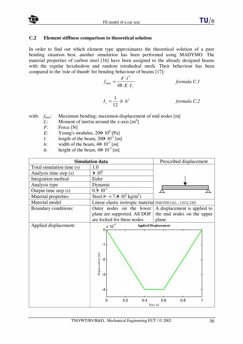
36
FE model of a car seat
TNO/WT/BV/R&D, Mechanical Engineering EUT / © 2002
C.2 Element stiffness comparison to theoretical solution
In order to find out which element type approximates the theoretical solution of a purebending situation best, another simulation has been performed using MADYMO. Thematerial properties of carbon steel [16] have been assigned to the already designed beamswith the regular hexahedron and random tetrahedral mesh. Their behaviour has beencompared to the 'rule of thumb' for bending behaviour of beams [17]:
zIE
lFf
⋅⋅⋅
=48
3
max formula C.1
3
12
1hbI z ⋅⋅= formula C.2
with: fmax: Maximum bending; maximum displacement of mid nodes [m]Iz: Moment of inertia around the z-axis [m4]F: Force [N]E: Young's modulus, 200• 109 [Pa]l: length of the beam, 200• 10-3 [m]b: width of the beam, 40• 10-3 [m]h: height of the beam, 40• 10-3 [m]
Simulation data Prescribed displacementTotal simulation time (s) 1.0Analysis time step (s) 1• 104
Integration method EulerAnalysis type DynamicOutput time step (s) 0.5• 10-1
Material properties Steel (• = 7.8• 103 kg/m3)Material model Linear elastic isotropic material (MATERIAL.ISOLIN)Boundary conditions: Outer nodes on the lower
plane are supported. All DOFare locked for these nodes.
A displacement is applied tothe mid nodes on the upperplane.
Applied displacement:
0 0.2 0.4 0.6 0.8 1
-4
-3
-2
-1
0x 10
4-4 Applied Displacement
Time [s]
Dis
pla
cem
ent [
m]

37
FE model of a car seat
TNO/WT/BV/R&D, Mechanical Engineering EUT / © 2002
During the simulations, the Von Mises stresses [N/m2] are calculated and the states inaccordance with the maximum displacements can be seen in the figure C.5. The maximumprescribed displacement is the same for both beams, but higher stresses take place at thebeams consisting of tetrahedral elements. These higher stresses can be explained by the factthat tetrahedral-elements behave stiffer than hexahedron elements as a result of theirgeometrical difference. This effect has also been seen in the simulations with foam materialbehaviour (Appendix C.1). The small deviance from total symmetry of the pressuredistribution can be explained by the same reason as mentioned in appendix C.1; the mesh isnot made by reflecting the mesh of a half meshed beam.
During the simulation, the forces on a few predefined nodes have also been monitored. Theforces of the mid nodes (i.e. the nodes that have a prescribed displacement) are summarisedbelow for the state where the maximum displacement is first reached and shows the largestforces:
Maximum Force in Z-direction [N] at t=400 msnodeHexa8-beam Tetramesh-beam
1 2.02888• 104 1.80933• 104
2 2.02888• 104 2.14835• 104
3 4.05777• 104 5.38181• 104
4 4.05777• 104 5.27957• 104
5 4.05777• 104 4.29285• 104
• 1.623107• 105 1.891191• 105
The total necessary force (cumulative force of all nodes 1-5, • ) in order to achieve theprescribed maximum displacement of 4• 10-4 m at t=0.4 s is estimated 15.6 % higher by the
Figure C.5: Von Mises stresses for the maximum state of the bending simulation
Von Mises stresses [N/m2]
Hexa8-beam
Tetramesh-beam

38
FE model of a car seat
TNO/WT/BV/R&D, Mechanical Engineering EUT / © 2002
tetramesh-beam than by the hexa8-beam. Pure theoretical tetrahedral elements are about 30 %stiffer than hexahedron elements, but due to the 4.2 times more elements in the tetramesh-beam, the stiffness is corrected to a difference of 15.6 % in this simulation.However, both beams approximate the theoretical solution of a required force of 1.024• 105 Npoor. This can be explained by the fact that the theoretical solution assumes a 'long' beam. A'long' beam is supposed to have a length to width ratio of 20:1 [17]. In the simulated beamsthis ratio is no more than 5:1. Although both beams have a very poor estimation of the trueforce, it can be concluded that the hexahedron beam with a difference of 58.5 % to the exactsolution gives a better approximation than the tetrahedral beam that has a difference of 84.7%. A longer beam would possibly reduce the difference between the two beams slightly as aconsequence of the difference in growth of elements, but it is very unlikely that anotherconclusion would be drawn.

39
FE model of a car seat
TNO/WT/BV/R&D, Mechanical Engineering EUT / © 2002
Appendix D: Pictures from the final seat cushion model

40
FE model of a car seat
TNO/WT/BV/R&D, Mechanical Engineering EUT / © 2002
Appendix E: Set-up for experiments with the foam material
For the characterisation of the foam material parameters it is recommended to perform someexperiments. Some preliminary investigation was performed during this study. This appendixobtains five recommended experiments to perform in the future.
The first experiment will provide the visco-elastic behaviour of the foam in terms of the stressrelaxation as a function of the deformation.
The strain rate dependency can be illustrated by a second experiment. A linear strain variationwill be applied at different velocities (v1, v2, .. vn). This will result in a collection of hysteresisloops.
The third experiment will provide information about the total stress-strain curve. In order todetermine the stress-strain curve of the foam, it is advisable to determine the slopes ofdifferent smaller regions that can be regarded as linear. For these different parts, the (σ,ε)-curve can be linearised. At different preloading states a sinusoidal movement can be appliedthat will characterize a small strain-area on the stress-strain curve. The applied loading of thespecimen is recommended to be a harmonic vibration with increasing frequency from 1 to 20Hz., covering the most important frequency range for comfort. A sinusoid has a continuousderivative, which makes it easier to prescribe mechanically than for example a zigzag or
Time
Figure E.1: Experiment to show the elastic behaviour (left), and expected data (right)
Time
Stre
ss
Stra
in
V1
Vn
V1
Vn
Figure E.2: Experiment to show the strain rate dependency (left), and expected data (right)
Time Time
Stre
ss
Stra
in
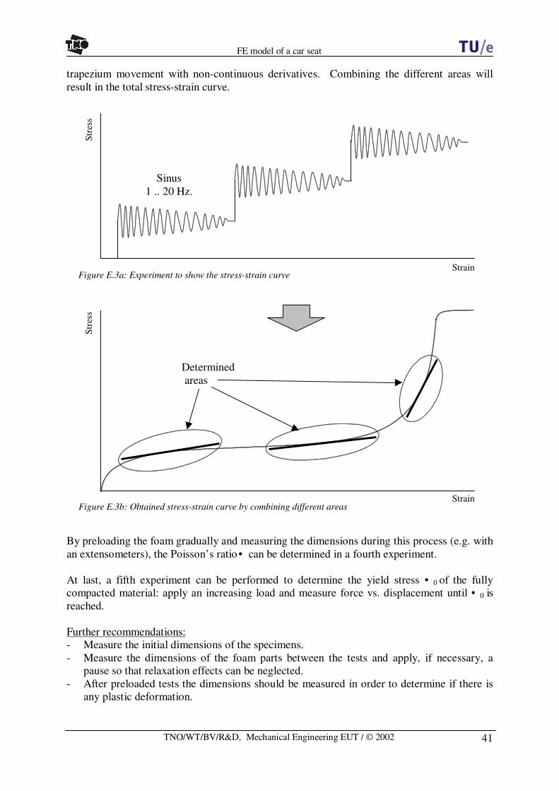
41
FE model of a car seat
TNO/WT/BV/R&D, Mechanical Engineering EUT / © 2002
trapezium movement with non-continuous derivatives. Combining the different areas willresult in the total stress-strain curve.
By preloading the foam gradually and measuring the dimensions during this process (e.g. withan extensometers), the Poisson’s ratio • can be determined in a fourth experiment.
At last, a fifth experiment can be performed to determine the yield stress • 0 of the fullycompacted material: apply an increasing load and measure force vs. displacement until • 0 isreached.
Further recommendations:- Measure the initial dimensions of the specimens.- Measure the dimensions of the foam parts between the tests and apply, if necessary, a
pause so that relaxation effects can be neglected.- After preloaded tests the dimensions should be measured in order to determine if there is
any plastic deformation.
Strain
Stre
ss
Sinus1 .. 20 Hz.
Figure E.3a: Experiment to show the stress-strain curve
Stre
ss
StrainFigure E.3b: Obtained stress-strain curve by combining different areas
Determinedareas