FE-ANALYSES TO STUDY THE EFFECT OF ... Patras.pdfFRPRCS-8 University of Patras, Patras, Greece, July...
10
FRPRCS- University of Patras, Patras, Greece, July 16-18, 2007 8 FE-ANALYSES TO STUDY THE EFFECT OF TEMPERATURE ON DEBONDING OF EXTERNALLY BONDED CFRP Ernst KLAMER 1 Dick HORDIJK 1,2 Ane DE BOER 3 1 Department of Architecture, Building and Planning, Eindhoven University of Technology, The Netherlands 2 Adviesbureau ir. J.G. Hageman B.V., Rijswijk, The Netherlands 3 Ministry of Transport, Public Works and Water Management, Utrecht, The Netherlands Keywords: externally bonded reinforcement, CFRP, temperature, debonding, finite element analysis. 1 INTRODUCTION The use of Externally Bonded Reinforcement based on Fiber Reinforced Polymers (EBR FRP) has become increasingly popular in the construction industry lately. Strengthening of existing concrete structures with FRP materials has proven to be a cost-effective and durable strengthening technique. The extensive amount of experimental, numerical and analytical research into this relatively new strengthening technique confirms the wide interest. By now, guidelines have become available for the construction industry [1,2] and numerous applications have been realized worldwide. Despite these developments, some questions have still remained unanswered. Debonding of the FRP, which generally governs the failure of a strengthened structure, has still not been fully understood and new developments, like anchoring and prestressing of FRP, are continuously going on. One of the questions that so far has received only little attention is the effect of the ambient temperature on the debonding behavior of externally bonded FRP [3]. Temperature changes will induce additional thermal stresses, due to the significant difference in the Coefficient of Thermal Expansion (CTE) between concrete (α c ≈ 10 × 10 -6 /°C) and e.g. CFRP (α f ≈ -1 × 10 -6 /°C in the fiber direction). The material properties of the concrete, adhesive and CFRP and the bond between these materials will also change with changing temperature. This particularly applies for the adhesive, as the strength and stiffness will drop significantly when the glass-transition temperature is reached (T g ≈ 45°C – 80°C for most cold curing epoxies). Both the difference in the coefficient of thermal expansion and the changing material properties may affect the load level at which debonding occurs. 2 PREVIOUS WORK So far, only limited research has been carried out into the influence of temperature on the debonding of externally bonded FRP. Experimental research into externally bonded steel strips was performed by Tadeu and Branco [4]. However, unlike FRP, steel has almost the same coefficient of thermal expansion as concrete, which means that hardly any thermal stresses had developed in between the steel strips and the concrete. A reduction of the failure load was found with an increase in temperature, which was expected to be caused by the changed properties of the adhesive. Blontrock [5] carried out similar double-lap shear tests with externally bonded CFRP laminates. Increasing the temperature from 20°C to 40°C resulted in a significant increase in failure load (41%), while for a further increase in temperature a decreasing failure load was found. Wu et al. [6] carried out similar double-lap shear tests, which, opposite to the results of Blontrock, showed a reduction of the failure load with increasing temperature. Di Tommaso et al. [7] investigated the influence of temperature in three point bending tests at temperatures ranging from -100°C up to 40°C. Both in- and decreasing the temperature resulted in a decreasing failure load. The experimental results from the literature have shown that the influence of temperature can be significant. However, based on the reported failure loads as function of the temperature no distinctive conclusions can be drawn. It is also not known to what extent the applied test setup had influenced the results and to what extent thermal stresses were developed during heating of the specimens. It was therefore decided to carry out additional tests and to compare the test results with Finite Element (FE-) analyses. FE-analyses can give insight in, for example, the development of stresses in the interface in between the CFRP and concrete, which is very difficult to determine experimentally. Furthermore, FE- analyses make it possible to carry out a parameter study without the need of expensive specimens. 1
Transcript of FE-ANALYSES TO STUDY THE EFFECT OF ... Patras.pdfFRPRCS-8 University of Patras, Patras, Greece, July...

FRPRCS- University of Patras, Patras, Greece, July 16-18, 2007 8
FE-ANALYSES TO STUDY THE EFFECT OF TEMPERATURE ON
DEBONDING OF EXTERNALLY BONDED CFRP
Ernst KLAMER 1 Dick HORDIJK 1,2 Ane DE BOER 3
1 Department of Architecture, Building and Planning, Eindhoven University of Technology, The Netherlands
2 Adviesbureau ir. J.G. Hageman B.V., Rijswijk, The Netherlands 3 Ministry of Transport, Public Works and Water Management, Utrecht, The Netherlands
Keywords: externally bonded reinforcement, CFRP, temperature, debonding, finite element analysis.
1 INTRODUCTION
The use of Externally Bonded Reinforcement based on Fiber Reinforced Polymers (EBR FRP) has
become increasingly popular in the construction industry lately. Strengthening of existing concrete structures with FRP materials has proven to be a cost-effective and durable strengthening technique. The extensive amount of experimental, numerical and analytical research into this relatively new strengthening technique confirms the wide interest. By now, guidelines have become available for the construction industry [1,2] and numerous applications have been realized worldwide. Despite these developments, some questions have still remained unanswered. Debonding of the FRP, which generally governs the failure of a strengthened structure, has still not been fully understood and new developments, like anchoring and prestressing of FRP, are continuously going on.
One of the questions that so far has received only little attention is the effect of the ambient temperature on the debonding behavior of externally bonded FRP [3]. Temperature changes will induce additional thermal stresses, due to the significant difference in the Coefficient of Thermal Expansion (CTE) between concrete (αc ≈ 10 × 10-6 /°C) and e.g. CFRP (αf ≈ -1 × 10⁻⁶ /°C in the fiber direction). The material properties of the concrete, adhesive and CFRP and the bond between these materials will also change with changing temperature. This particularly applies for the adhesive, as the strength and stiffness will drop significantly when the glass-transition temperature is reached (Tg ≈ 45°C – 80°C for most cold curing epoxies). Both the difference in the coefficient of thermal expansion and the changing material properties may affect the load level at which debonding occurs.
2 PREVIOUS WORK
So far, only limited research has been carried out into the influence of temperature on the
debonding of externally bonded FRP. Experimental research into externally bonded steel strips was performed by Tadeu and Branco [4]. However, unlike FRP, steel has almost the same coefficient of thermal expansion as concrete, which means that hardly any thermal stresses had developed in between the steel strips and the concrete. A reduction of the failure load was found with an increase in temperature, which was expected to be caused by the changed properties of the adhesive. Blontrock [5] carried out similar double-lap shear tests with externally bonded CFRP laminates. Increasing the temperature from 20°C to 40°C resulted in a significant increase in failure load (41%), while for a further increase in temperature a decreasing failure load was found. Wu et al. [6] carried out similar double-lap shear tests, which, opposite to the results of Blontrock, showed a reduction of the failure load with increasing temperature. Di Tommaso et al. [7] investigated the influence of temperature in three point bending tests at temperatures ranging from -100°C up to 40°C. Both in- and decreasing the temperature resulted in a decreasing failure load.
The experimental results from the literature have shown that the influence of temperature can be significant. However, based on the reported failure loads as function of the temperature no distinctive conclusions can be drawn. It is also not known to what extent the applied test setup had influenced the results and to what extent thermal stresses were developed during heating of the specimens. It was therefore decided to carry out additional tests and to compare the test results with Finite Element (FE-) analyses. FE-analyses can give insight in, for example, the development of stresses in the interface in between the CFRP and concrete, which is very difficult to determine experimentally. Furthermore, FE-analyses make it possible to carry out a parameter study without the need of expensive specimens.
1
FRPRCS- University of Patras, Patras, Greece, July 16-18, 2007 8
3 EXPERIMENTAL STUDY
3.1 Introduction This paper focuses on the Finite Element (FE-) study. Therefore, only the highlights of the
experimental study, which is described in detail in [8], will be presented. Two different test setups were used to investigate the influence of temperature on the debonding; a double-lap shear test setup and a three point bending test setup. Two different concrete grades, further called concrete grade A (fcm,cube = 40.1 N/mm²) and B (fcm,cube = 70.8 N/mm²), were used in the experiments. The specimens were loaded until failure at several temperatures in the range from -20°C up to 100°C.
3.2 Double-lap shear tests
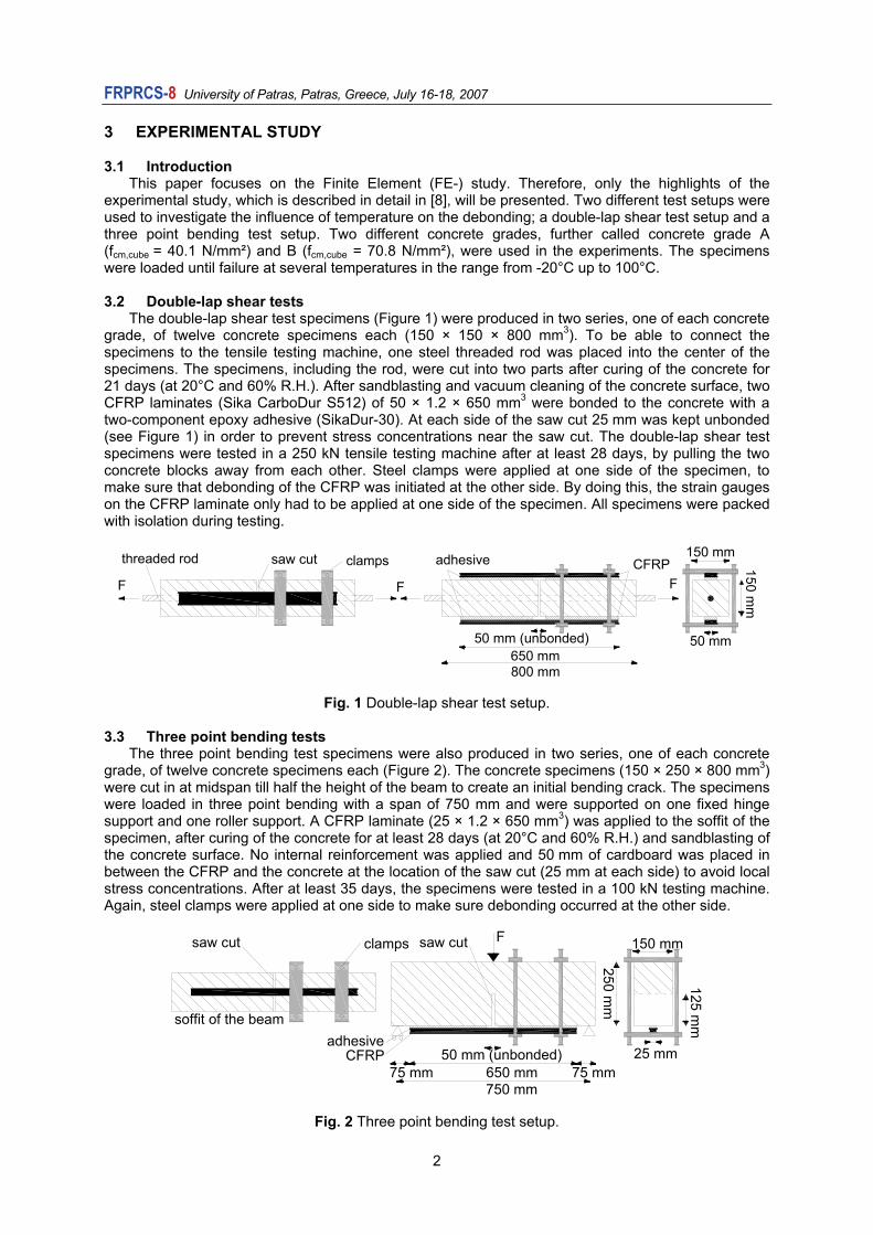
The double-lap shear test specimens (Figure 1) were produced in two series, one of each concrete grade, of twelve concrete specimens each (150 × 150 × 800 mm3). To be able to connect the specimens to the tensile testing machine, one steel threaded rod was placed into the center of the specimens. The specimens, including the rod, were cut into two parts after curing of the concrete for 21 days (at 20°C and 60% R.H.). After sandblasting and vacuum cleaning of the concrete surface, two CFRP laminates (Sika CarboDur S512) of 50 × 1.2 × 650 mm3 were bonded to the concrete with a two-component epoxy adhesive (SikaDur-30). At each side of the saw cut 25 mm was kept unbonded (see Figure 1) in order to prevent stress concentrations near the saw cut. The double-lap shear test specimens were tested in a 250 kN tensile testing machine after at least 28 days, by pulling the two concrete blocks away from each other. Steel clamps were applied at one side of the specimen, to make sure that debonding of the CFRP was initiated at the other side. By doing this, the strain gauges on the CFRP laminate only had to be applied at one side of the specimen. All specimens were packed with isolation during testing.
800 mm650 mm
150 mm
150 mm
50 mm50 mm (unbonded)
CFRPsaw cut adhesiveclamps
FFF
threaded rod
Fig. 1 Double-lap shear test setup.
3.3 Three point bending tests The three point bending test specimens were also produced in two series, one of each concrete
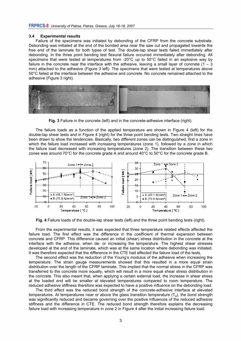
grade, of twelve concrete specimens each (Figure 2). The concrete specimens (150 × 250 × 800 mm3) were cut in at midspan till half the height of the beam to create an initial bending crack. The specimens were loaded in three point bending with a span of 750 mm and were supported on one fixed hinge support and one roller support. A CFRP laminate (25 × 1.2 × 650 mm3) was applied to the soffit of the specimen, after curing of the concrete for at least 28 days (at 20°C and 60% R.H.) and sandblasting of the concrete surface. No internal reinforcement was applied and 50 mm of cardboard was placed in between the CFRP and the concrete at the location of the saw cut (25 mm at each side) to avoid local stress concentrations. After at least 35 days, the specimens were tested in a 100 kN testing machine. Again, steel clamps were applied at one side to make sure debonding occurred at the other side.
750 mm650 mm
250 mm
150 mm
25 mm50 mm (unbonded)
saw cut
CFRPadhesive
125 mmsoffit of the beam
75 mm75 mm
clamps Fsaw cut
Fig. 2 Three point bending test setup.
2
FRPRCS- University of Patras, Patras, Greece, July 16-18, 2007 8
3.4 Experimental results Failure of the specimens was initiated by debonding of the CFRP from the concrete substrate.
Debonding was initiated at the end of the bonded area near the saw cut and propagated towards the free end of the laminate for both types of test. The double-lap shear tests failed immediately after debonding. In the three point bending test flexural failure occurred immediately after debonding. All specimens that were tested at temperatures from -20°C up to 50°C failed in an explosive way by failure in the concrete near the interface with the adhesive, leaving a small layer of concrete (1 – 3 mm) attached to the adhesive (Figure 3 left). The specimens that were tested at temperatures above 50°C failed at the interface between the adhesive and concrete. No concrete remained attached to the adhesive (Figure 3 right).
Fig. 3 Failure in the concrete (left) and in the concrete-adhesive interface (right). The failure loads as a function of the applied temperature are shown in Figure 4 (left) for the
double-lap shear tests and in Figure 4 (right) for the three point bending tests. Two straight lines have been drawn to show the tendencies. Basically, two different zones can be distinguished, first a zone in which the failure load increased with increasing temperatures (zone 1), followed by a zone in which the failure load decreased with increasing temperatures (zone 2). The transition between these two zones was around 70°C for the concrete grade A and around 40°C to 50°C for the concrete grade B.
Fig. 4 Failure loads of the double-lap shear tests (left) and the three point bending tests (right). From the experimental results, it was expected that three temperature related effects affected the
failure load. The first effect was the difference in the coefficient of thermal expansion between concrete and CFRP. This difference caused an initial (shear) stress distribution in the concrete at the interface with the adhesive, when de- or increasing the temperature. The highest shear stresses developed at the end of the laminate, which was at the same location where debonding was initiated. It was therefore expected that the difference in the CTE had affected the failure load of the tests.
The second effect was the reduction of the Young’s modulus of the adhesive when increasing the temperature. The strain gauge measurements showed that this resulted in a more equal strain distribution over the length of the CFRP laminate. This implied that the normal stress in the CFRP was transferred to the concrete more equally, which will result in a more equal shear stress distribution in the concrete. This also meant that, when applying a certain external load, the increase in shear stress at the loaded end will be smaller at elevated temperatures compared to room temperature. The reduced adhesive stiffness therefore was expected to have a positive influence on the debonding load.
The third effect was the reduced bond strength of the concrete-adhesive interface at elevated temperatures. At temperatures near or above the glass transition temperature (Tg), the bond strength was significantly reduced and became governing over the positive influences of the reduced adhesive stiffness and the difference in CTE. The reduced bond strength therefore explains the decreasing failure load with increasing temperature in zone 2 in Figure 4 after the initial increasing failure load.
3

FRPRCS- University of Patras, Patras, Greece, July 16-18, 2007 8
4 FINITE ELEMENT MODEL 4.1 Introduction
The aim of the Finite Element (FE-) study was to simulate the behavior and failure of the specimens at low and high temperatures and to verify the findings of the experimental research. The FE-analyses were performed using the Finite Element Analysis program DIANA 9.1 [9]. 4.2 Double-lap shear test
Only half the double-lap shear test specimen was modeled because of symmetry (Figure 5). The modeled part itself was also symmetric, but, because the threaded rod, two supports and the external load were all located on the symmetry line, it was decided not to make use of this symmetry. The model was supported with roller supports at the end of the CFRP laminates near the saw cut and at both ends of the threaded rod. The external load was applied at the end of the threaded rod.
Three different types of elements were used in the FE-model. The concrete, CFRP and adhesive were modeled with eight node plane stress elements. The threaded rod was modeled with an embedded reinforcement bar, which basically added stiffness to the FE-model at the location where the reinforcement bar was located. Failure in the experiments occurred in the concrete at the interface with the adhesive. It was therefore decided to apply interface elements in between the adhesive and concrete elements. Nonlinear bond-slip properties were assigned to these elements to simulate the behavior of this connection. More details of the applied interface elements and the nonlinear behavior of these elements are given in Section 4.5. For all other elements, linear elastic material properties were applied, as no other non-linear behavior had occurred in the experiment.
Fig. 5 Finite Element model for the double-lap shear test.
4.3 Three point bending test The FE-model of the three point bending test is shown in Figure 6. The beam was supported on a
fixed hinge support (left) and a roller support (right). The load was applied on top of the beam at midspan. Because the beam was cut at midspan till half the height of the beam, no elements were applied over the lower half of the midspan cross section, as can be seen in the detail in Figure 6. Also no elements were applied at the non-bonded part between the concrete and the adhesive, 25 mm at each side of the saw cut.
Fig. 6 Finite Element model for the three point bending test.
4

FRPRCS- University of Patras, Patras, Greece, July 16-18, 2007 8
The concrete, adhesive and CFRP were modeled with eight node linear elastic plane stress elements. Interface elements were again applied for the contact zone between the adhesive and the concrete, to model the nonlinear bond-slip behavior of this connection. Furthermore, interface elements were used at the upper half of the midspan cross section to model the (discrete) cracking of the concrete at this location. 4.4 Material properties
The material properties were determined in the experimental research. The average material properties, which were used in the FE-analyses for the plane stress elements, are shown in Table 1, including the coefficient of thermal expansion. The material properties of the CFRP were not affected by temperature until 150°C, according to the manufacturer. The Young’s modulus of the adhesive, however, turned out to be highly dependent on the applied temperature and was therefore experimentally determined (see Figure 7 left). The Young’s modulus of the concrete also depends on the applied temperature and was taken according to the Model Code 1990 [10] (Figure 7 right):
= −ci ci 0E (T) E (1.06 0.003T / T ) (1)
Table 1 Applied material properties of the plane stress elements at 20°C.
Concrete Adhesive CFRP
A B Young’s modulus (Eci) 26,800 N/mm2 31,100 N/mm2 12,830 N/mm2 165,000 N/mm2 Poisson’s ratio (νc) 0.2 0.2 0.3 0.35 CTE (αc) 10.2 × 10⁻⁶ /°C 11.3 × 10⁻⁶ /°C 26 × 10-6 /°C -0.3 × 10⁻⁶ /°C
Fig. 7 Temperature - Young’s modulus relation of the adhesive (left) and concrete (right) [10].
4.5 Interface properties
The applied interface elements for the concrete-adhesive joint and for the bending crack were line interface elements with three nodes at each side of the element (Figure 8 left). A line interface element describes the relation between the stresses (tn en tt) and the relative displacements (Δux en Δuy). The normal stress (tn) is defined in the direction perpendicular to the lines and describes the Mode I behavior. The shear stress is defined parallel to the lines and describes the Mode II behavior. The displacement in the Mode II direction (Δuy) is also called slip (s). Mode I and Mode II behavior are not coupled in the analyses, which mean that they do not depend on each other.
For all interface elements, a dummy height of 0.1 mm was applied. For the interface elements of the discrete crack at midspan in the three point bending tests, a linear tension softening behavior was applied (Figure 8b). The tensile strength was experimentally determined and was equal to 3.07 N/mm2 and 3.79 N/mm2 for respectively concrete grade A and B. The area under the linear softening diagram corresponds to the fracture energy of concrete (GF
I) and was taken equal to 100 J/m2 for both concrete grades. To simulate the Mode II behavior of the concrete after cracking, the shear stiffness of the interface elements was reduced to zero after the normal stress has reached the tensile strength.
5

FRPRCS- University of Patras, Patras, Greece, July 16-18, 2007 8
Δuult
GF
ft,max
tn
I
sf1 = τmax(tc/Gc)
τd,max
tt
sf0
II
τd,max = 1.8 kb fctm
slip [mm]displacement [mm]no
rmal
str
ess
[N/m
m
shea
r str
ess
[N/m
m²]
Δucr
12 3
4
z
y 5 6
topology
x
tn
tt
tractions
GF=kc² kb² cF fctm
(a) (b) (c)
sf1 = 0.06 mm
Dörr
Holzenkämpfer
Fig. 8 Properties of the interface elements [9].
For both test setups, it was expected that, at room temperature, failure of the specimen occurred in the concrete at the interface with the adhesive due to high shear stresses. It was therefore decided to apply a nonlinear bond-slip behavior for these interface elements. One of the most used models for this type of failure is the model of Holzenkämpfer [11], modified by Neubauer and Rostásy [12]. The model of Holzenkämpfer is based on a bilinear bond-slip (τ-s) relation as can be seen in Figure 8c. The mode II fracture energy (GII
F) is related to the tensile strength on concrete (fctm). The two factors kc and kb account for the state of compaction of the concrete and for the geometry respectively. cf is obtained through calibrations with test results by Holzenkämpfer (cf = 0.092) [11] and Neubauer and Rostásy (cf = 0.202) [12]. The value according to Holzenkämpfer was used in the FE-analyses. The model of Dörr, also shown in Figure 8c, will be explained in section 5.1. In the normal direction perpendicular to the concrete surface (Mode I) only linear elastic properties were applied. 5 RESULTS OF THE FE-ANALYSES 5.1 Load-displacement double-lap shear tests
Figure 9 shows the experimental and numerical load-displacement curves for the double-lap shear tests at -20°C, 20°C, 50°C and 70°C for concrete grade A. Similar results were found for concrete grade B. The plotted displacement on the horizontal axis corresponds to the displacement measured over the saw cut.
Fig. 9 Load-displacement curves of the double-lap shear tests at -20°C, 20°C, 50°C and 70°C.
6

FRPRCS- University of Patras, Patras, Greece, July 16-18, 2007 8
It can be seen that, until 50°C, the load-displacement curves found with the FE-analyses showed good similarity with the experimental results. The only difference was the displacement at failure, which was significantly larger for the FE-analyses. It is expected that this was caused by the explosive type of failure in the experiment, which made it impossible to measure these large displacements.
It turned out that the numerical failure load also increased with increasing temperatures, which corresponded to the experimental results. At 70°C, however, the results of the FE-analysis corresponded less with the experimental results. At this temperature, the failure mechanism in the experiments was changed from failure in the concrete to failure in the interface exactly in between the adhesive and the concrete, as was shown in Figure 3. It can therefore be concluded that the applied bond-slip model for the interface elements was not valid anymore at this temperature, as the model of Holzenkämpfer only accounts for concrete failure.
To simulate the behavior of the specimens at 70°C, it was necessary to apply a different bond-slip model. The cubic function of Dörr [13] (Figure 8) turned out to give better results. The maximum shear strength was determined by fitting the numerical results to the experimental results. A maximum shear strength of 1.7 N/mm2 was found for the lower strength concrete specimens (A) and 1.4 N/mm2 for the higher strength concrete specimens (B). No clear relation was found between the concrete grade and the maximum shear strength. This is probably due to the fact that, at 70°C, the strength will depend more on the quality of the execution of the CFRP bonding and on the concrete surface conditions, which will result in a large variation in the shear strength.
5.2 Load-displacement three point bending tests
The load-displacement curves of the three point bending tests (concrete grade B) are shown in Figure 10. The displacement was measured at midspan. The results were similar to the results of the double-lap shear tests. Until 40°C, the numerical results showed good similarity with the experimental results. However, at 70°C, the results of the FE-analysis did not correspond to the experiments anymore. Again, the model of Dörr [13] gave better results at this temperature. A maximum shear strength of 1.3 N/mm2 was found for the low strength concrete and 0.5 N/mm2 (see Figure 10, FE-analysis Dörr a) and 0.9 N/mm2 (see Figure 10, FE-analysis Dörr b) for the higher strength concrete at 70°C. It was again expected that the shear strength highly depended on the quality of the execution and on the concrete surface conditions at temperatures above the glass transition temperature of the adhesive.
Fig. 10 Load-displacement curves of the three point bending tests at -20°C, 20°C, 40°C and 70°C.
7

FRPRCS- University of Patras, Patras, Greece, July 16-18, 2007 8
It can also be seen that the failure load increased with increasing temperatures until 40°C. At 70°C however, the failure mode had changed and a significant lower failure load was found. In the experimental research, it was concluded that the increasing failure load was caused by the difference in CTE and the changed Young’s modulus of the adhesive. The decreasing failure load was expected to be caused by the changed failure mode and bond strength of the concrete-adhesive interface. To verify these conclusions, each of these effects will be discussed separately in the next sections.
5.3 Effect of the difference in the coefficient of thermal expansion
First effect of temperature was the development of thermal stresses, due to the difference in the coefficient of thermal expansion between concrete, adhesive and CFRP. Figure 11 shows the normal stress in the CFRP laminate (left) and the shear stress in the concrete at the interface with the adhesive (right) after changing the temperature from 20°C to -20°C, 50°C and 70°C respectively. No external load was applied yet. The normal stress in the CFRP and shear stress in the concrete were also analytically determined with the model of Di Tommaso et al. [7] (Analytical in Figure 11).
Fig. 11 Normal stress in the CFRP (left) and shear stress in the concrete-adhesive interface (right). Changing the temperature caused thermal stresses in both the CFRP and the concrete. The
normal stresses in the CFRP laminate were negligible compared to the tensile strength of CFRP (about 2% of ffm). The shear stresses in the concrete at the end of the bonded length however were relatively high compared to the shear strength of concrete. Moreover, applying a load on the specimens will cause high shear stresses at exactly the same location, as can be seen in Figure 11 (right) for 10 kN. Increasing the temperature caused shear stresses at the loaded end that acted in the opposite direction as the shear stresses due to loading. It can therefore be concluded that increasing the temperature had a positive effect on the failure load, because the initial shear stresses due to the difference in the coefficient of thermal expansion first had to be compensated by applying the load. The load which was needed to compensate the shear stress at the loaded end turned out to be almost equal to the increase in failure load.
5.4 Effect of the reduced Young’s modulus
The model of Di Tommaso et al., which was used for the analytical stress distributions in Figure 11, does not take the Young’s modulus of the adhesive into account. The analytical stress distributions therefore did not show the effect of the reduced Young’s modulus of the adhesive at elevated temperature. Especially at 70°C, it can be seen that the stress distributions found with the FE-analyses were significantly different from the analytical distributions. The shear stress at the end of the bonded length at 70°C became even lower than the shear stress at 50°C. It can therefore be concluded that the model of Di Tommaso is only valid for temperatures at which the Young’s modulus of the adhesive is not significantly affected.
From the experimental results, it was expected that the reduced Young’s modulus would cause a higher failure load, due to the more equal shear stress distribution. It was therefore decided to carry out a numerical parameter study. Figure 12 (left) shows the effect of varying the Young’s modulus of the adhesive (Ea) between 1% and 200% of the initial Young’s modulus at 20°C (12,830 N/mm²). The analyses have been carried out for eight different bonded lengths: 25 mm, 50 mm, 75 mm, 100 mm, 150 mm, 200 mm, 250 mm and 300 mm (see Figure 12 left for the definition of the bonded length). The bilinear bond-slip behavior, which was applied for the interface elements, and the Young’s modulus of the concrete were kept the same for all analyses.
8

FRPRCS- University of Patras, Patras, Greece, July 16-18, 2007 8
Fig. 12 Effect of the Young’s modulus on the failure load and anchorage length. Decreasing the Young’s modulus of the adhesive initially caused a slowly decreasing failure load.
However, from a Young’s modulus of 2% of Ea(20°C), the failure load suddenly started to increase with decreasing Ea. Figure 12 (right) shows this relation between the Young’s modulus of the adhesive and the failure load of the specimens with a 300 mm bonded length in a different way. For very small Young’s moduli of the adhesive, the shear stress distribution over the bonded length changed from a distribution with a peak in the shear stress away from the loaded end to a distribution with the peak in shear stress exactly at the loaded end, as can be seen in Figure 13. It also became clear that a more equal shear stress distribution not necessarily will decrease the area under the shear stress distribution, and thus the failure load. The area will increase at the left side of the peak, but decrease at the right side of the peak.
Fig. 13 Effect of the Young’s modulus on the shear stress distribution at the failure load. It can also be seen in Figure 12 (left) that, from a certain bonded length, the failure load did not
increase anymore. This length is called the anchorage length and was also expected to be affected by temperature (see Figure 12 left for a definition of the anchorage length at 20°C). The relation between the anchorage length and the Young’s modulus of the adhesive was plotted in Figure 12 (right). The anchorage length initially slowly decreased with a decreasing Young’s modulus. However, when the Young’s modulus of the adhesive became very small, the anchorage length increased significantly.
5.5 Effect of the changed failure mode and reduced bond strength
The positive effect of a very small Young’s modulus of the adhesive was not found in the experiment, as the failure mode changed from failure in the concrete to failure in the concrete-adhesive interface at temperatures above the glass transition temperature of the adhesive (Tg). From the numerical load-displacement curves in Figure 9 and 10, it was concluded that the model of Holzenkämpfer could not be used at these temperatures anymore. Although the model of Dörr gave better numerical results, it can as yet not be used for guidelines, because so far no clear model is available for it. It was however shown that the bond strength was significantly reduced. It can therefore be concluded that (unprotected) FRP application cannot be used at temperatures above the glass transition temperature of the adhesive. For applications in environments where high temperatures are expected, special precautions have to be taken, like anchorage, isolation and/or a special adhesive.
9

FRPRCS- University of Patras, Patras, Greece, July 16-18, 2007 8
10
6 CONCLUSIONS AND RECOMENDATIONS The numerical results have shown that most of the findings of the experimental research can be
simulated and explained with FE-analyses. Changing the temperature had both positive and negative effects on the failure load of the investigated specimens. Three different effects were distinguished:
(1) The difference in the coefficient of thermal expansion between concrete, adhesive and CFRP caused shear stresses in the concrete at the interface with the adhesive. These shear stresses at the loaded end acted in the opposite direction as the shear stresses due to loading, when increasing the temperature. These shear stresses first had to be compensated and therefore had a positive effect.
(2) The reduced Young’s modulus of the adhesive at elevated temperatures caused a more equal shear stress distribution in the concrete, at the interface with the adhesive. Reducing the Young’s modulus initially caused a slightly decreasing failure load and decreasing anchorage length. However, when the Young’s modulus became very small (< 2% of Ea(20°C)) a positive effect on the failure load and a longer anchorage length was found. At temperatures where such small Young’s modulus can be expected (T > Tg), the third effect became governing over first two effects.
(3) The third effect was the changed failure mode and reduced bond strength of the concrete-adhesive interface at temperatures above Tg. A large scatter in bond strengths was found, which were all very low. It is therefore not recommended to apply FRP at temperatures above Tg. ACKNOWLEDGEMENTS
The authors would like to express their gratitude to the Dutch Ministry of Transport, Public Works
and Water Management for supporting the investigation both financially and with advice and to SIKA Nederland BV for supplying the CFRP and the adhesive. Furthermore the authors are indebted to the personnel of the Pieter van Musschenbroek laboratory, where the experiments were carried out.
REFERENCES [1] fib Task Group 9.3, fib bulletin 14. Externally bonded FRP reinforcement for RC structures,
fédération internationale du béton, Lausanne, Switzerland, 2001, 130 pp. [2] ACI, ACI 440.2R-02 Guide for the Design and Construction of Externally Bonded FRP
Systems for Strengthening Concrete Structures, American Concrete Institute, Farmington Hills, MI, USA, 2002, 45 pp.
[3] Harries, K.A., Porter, M.L., and Busel, J.P., "FRP materials and concrete - research needs", Concrete International, 25, 10, 2003, pp. 69-74.
[4] Tadeu, A.J.B. and Branco, F.J.F.G., "Shear tests of steel plates epoxy-bonded to concrete under temperature", Journal of Materials in Civil Engineering, 12, 1, 2000, pp. 74-80.
[5] Blontrock, H., "Analyse en modellering van de brandweerstand van betonelementen uitwendig versterkt met opgelijmde composietlaminaten", Ghent University, Ghent, Belgium, 2003.
[6] Wu, Z.S., Iwashita, K., Yagashiro, S., Ishikawa, T., and Hamaguchi, Y., "Temperature effect on bonding and debonding behavior between FRP sheets and concrete", Journal of the Society of Material Science, 54, 5, 2005, pp. 474-480.
[7] Di Tommaso, A., Neubauer, U., Pantuso, A., and Rostásy, F.S., "Behavior of adhesively bonded concrete-CFRP joints at low and high temperatures", Mechanics of Composite Materials, 37, 4, 2001, pp. 327-338.
[8] Klamer, E.L., Hordijk, D.A., and Janssen, H.J.M., "The influence of temperature on the debonding of externally bonded CFRP", FRPRCS7, Kansas City, MO, USA, 2005, pp. 1551-1570.
[9] TNO DIANA B.V., DIANA user's manual, TNO DIANA B.V., Delft, the Netherlands, 2005. [10] CEB, CEB-FIP model code 1990: design code, Comité Euro-International du Béton, Lausanne,
Switzerland, 1993, 460 pp. [11] Holzenkämpfer, P., Ingenieursmodelle des verbunds geklebter bewehrung für betonbauteile,
Westkreuz-Druckerei Ahrens KG, Berlin, Germany, 1997, 109 pp. [12] Neubauer, U. and Rostásy, F.S., "Bond Failure of Concrete Fiber Reinforced Polymer Plates
at Inclined Cracks – Experiments and Fracture Mechanics Model", 4th Int. Sym. Non-Metallic (FRP) Reinforcement for Concrete Structures, ACI, Baltimore, MD, USA, 1999, pp. 369-382.
[13] Dörr, K., "Ein beitrag zur berechnung von stahlbetonscheiben unter besonderer berücksichtingung des verbundverhaltens", University of Darmstadt, Darmstadt, Germany, 1980.