FDS-737-MX-MCP Instruction Sheet -...
20
FDS-737-MX-MCP Instruction Sheet FDS-737-MX-MCP-Information-Aug-2015 Version 1.0 1
Transcript of FDS-737-MX-MCP Instruction Sheet -...

FDS-737-MX-MCP Instruction Sheet
FDS-737-MX-MCP-Information-Aug-2015 Version 1.0 1

JetMax-737-MCP-Information-Sept-2015 Version 1.0 2
Features of a FDS-737-MX- MCP
MX Version includes the Bank Angle Selector and A/T Solenoid switch.
Bank Angle Selector: Rotate outer knob and point the arrow to the
required Bank Angle. There is no indication of the selected angle, only the
pointer.
A/T Solenoid Switch: The switch is held up in place by a solenoid. Requires
12V wires connected (as per manual).
To release the A/T switch you will press the A/T Disconnect switch on the
Throttle Lever (L or R, only 1 is required) two times. Once to release the
solenoid and the second time to cancel any Aural warning or Indicator light
(AFDS).
It is not recommended you force the switch down with the Solenoid
powered. That is not the proper method to release the A/T Switch in a
B737. (MX Model Only/ Use the A/T Disc switches on the Throttle Levers.)

JetMax-737-MCP-Information-Sept-2015 Version 1.0 3
Features of a FDS-737-MX- MCP
MX Version also includes the SPD INTV and ALT INTV switch.
Did you know?
The “+” mark let’s the technician
know where the panel power
connector is when removing the
real panels.

FDS-737-MX-MCP-Information-Aug-2015 Version 1.0 4
Parts List
FDS-737 MX-MCP
PART DESCRIPTION #
B737 MX-MCP Unit 1
Power Supply 1
USB Cable 1
IBL 5V Cable 6 Ft. long 1
A/T 12V Cable 6 Ft. long 1

FDS-737-MX-MCP-Information-Aug-2015 Version 1.0 5
Cable Connections
•Connect Yellow/Black wire to 12V source in DSTD.
•Connect Red/Black wires to 5V source or plug in 4 pin connector to
IBL Dist Board (Captain side)
•Connect 12V power supply to rear plug and power bar.
•Plug in USB cable and connect to Avionics PC
Note:
•Sim-Avionics will recognize the MCP in the SYSBoard Controller
after the driver self installs.
•ProSim, follow settings to add the MCP/G3 settings in the ProSim
Server. See their manual for Config settings. Also page 12 of this
manual. Run the ProSim MCP software.
•Project Magenta not supported at this time. No ETA
•iFly may be supported at a future date.
•PMDG update will be available at a future date. Interface in
development.
FDS-737-MX-MCP-Information-Aug-2015 Version 1.0 6
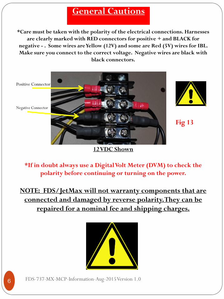
*Care must be taken with the polarity of the electrical connections. Harnesses
are clearly marked with RED connectors for positive + and BLACK for
negative - . Some wires are Yellow (12V) and some are Red (5V) wires for IBL.
Make sure you connect to the correct voltage. Negative wires are black with
black connectors.
Positive Connector
Negative Connector
12 VDC Shown
*If in doubt always use a Digital Volt Meter (DVM) to check the
polarity before continuing or turning on the power.
NOTE: FDS/JetMax will not warranty components that are
connected and damaged by reverse polarity. They can be
repaired for a nominal fee and shipping charges.
Fig 13
General Cautions
FDS-737-MX-MCP-Information-Aug-2015 Version 1.0 7
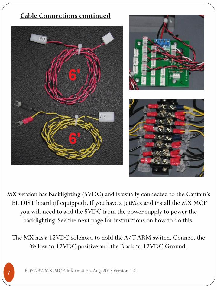
MX version has backlighting (5VDC) and is usually connected to the Captain’s
IBL DIST board (if equipped). If you have a JetMax and install the MX MCP
you will need to add the 5VDC from the power supply to power the
backlighting. See the next page for instructions on how to do this.
The MX has a 12VDC solenoid to hold the A/T ARM switch. Connect the
Yellow to 12VDC positive and the Black to 12VDC Ground.
Cable Connections continued
FDS-737-MX-MCP-Information-Aug-2015
Version 1.0 8
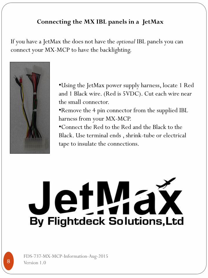
Connecting the MX IBL panels in a JetMax
If you have a JetMax the does not have the optional IBL panels you can
connect your MX-MCP to have the backlighting.
•Using the JetMax power supply harness, locate 1 Red
and 1 Black wire. (Red is 5VDC). Cut each wire near
the small connector.
•Remove the 4 pin connector from the supplied IBL
harness from your MX-MCP.
•Connect the Red to the Red and the Black to the
Black. Use terminal ends , shrink-tube or electrical
tape to insulate the connections.

FDS-737-MX-MCP-Information-Aug-2015 Version 1.0 9
DSTD Mounting Plate
* Only supplied with MX-MCP if not sent with DSTD or Glare package.
MCP Lower Plate 1
4-40 x 1/4 Philips Pan Head Inner Screws 4
4-40 x 3/8 Phillips Pan Head Outer screws 2
6-32 x 3/8 Philips Pan Head Rear screws 3
6-32 Speed Clips 3
4/40 x 3/8” on
outer holes only.
(2)
FDS-737-MX-MCP-Information-Aug-2015 Version 1.0 10
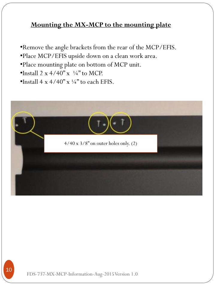
Mounting the MX-MCP to the mounting plate
•Remove the angle brackets from the rear of the MCP/EFIS.
•Place MCP/EFIS upside down on a clean work area.
•Place mounting plate on bottom of MCP unit.
•Install 2 x 4/40” x ¼” to MCP.
•Install 4 x 4/40” x ¼” to each EFIS.
4/40 x 3/8” on outer holes only. (2)
FDS-737-MX-MCP-Information-Aug-2015 Version 1.0 11
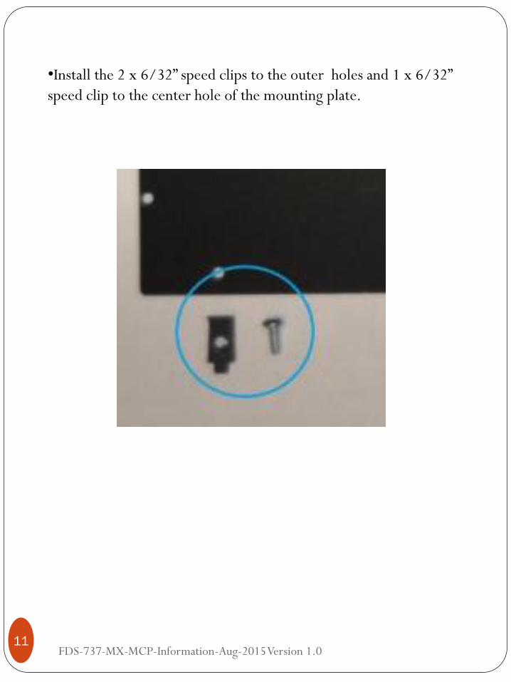
•Install the 2 x 6/32” speed clips to the outer holes and 1 x 6/32”
speed clip to the center hole of the mounting plate.

FDS-737-MX-MCP-Information-Aug-2015 Version 1.0 12
Slide completed unit into the Glareshield of the DSTD and install the
2 x 4/40” x 3/8” screws into the glareshield side brackets and EFIS’.
Install the 3 x 6/32” x 3/8” screws into the 3 rear speed clips.
Rear screws
Side screws
FDS-737-MX-MCP-Information-Aug-2015 Version 1.0 13
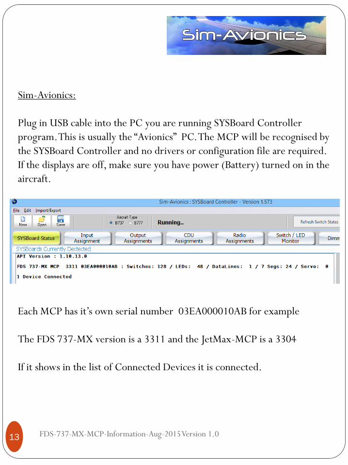
Sim-Avionics:
Plug in USB cable into the PC you are running SYSBoard Controller
program. This is usually the “Avionics” PC. The MCP will be recognised by
the SYSBoard Controller and no drivers or configuration file are required.
If the displays are off, make sure you have power (Battery) turned on in the
aircraft.
Each MCP has it’s own serial number 03EA000010AB for example
The FDS 737-MX version is a 3311 and the JetMax-MCP is a 3304
If it shows in the list of Connected Devices it is connected.
FDS-737-MX-MCP-Information-Aug-2015 Version 1.0 14
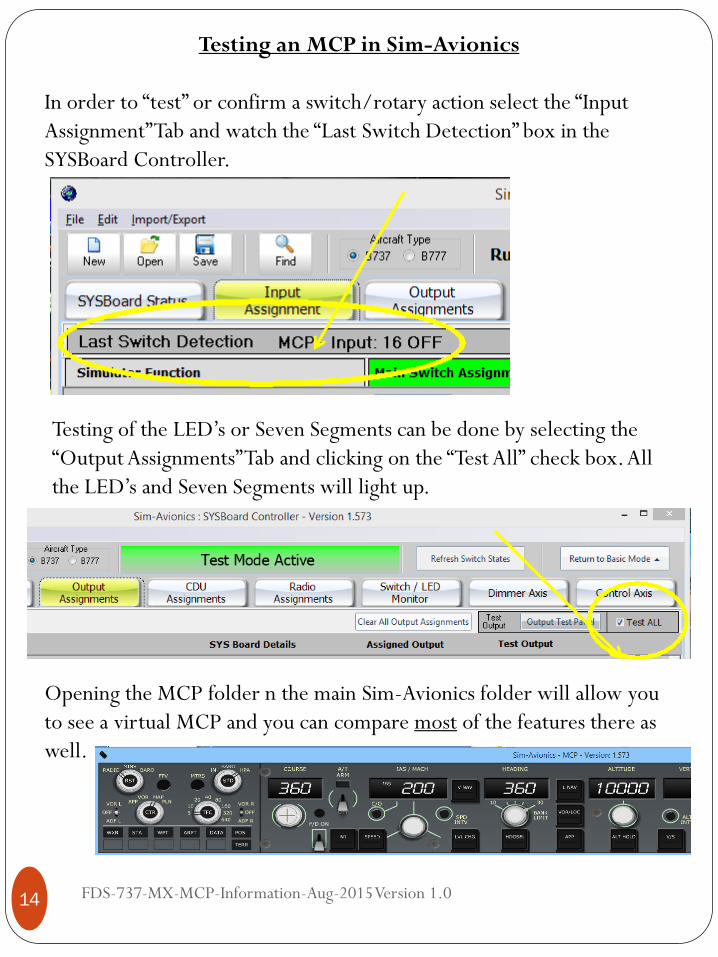
Testing an MCP in Sim-Avionics
In order to “test” or confirm a switch/rotary action select the “Input
Assignment” Tab and watch the “Last Switch Detection” box in the
SYSBoard Controller.
Testing of the LED’s or Seven Segments can be done by selecting the
“Output Assignments” Tab and clicking on the “Test All” check box. All
the LED’s and Seven Segments will light up.
Opening the MCP folder n the main Sim-Avionics folder will allow you
to see a virtual MCP and you can compare most of the features there as
well.

FDS-737-MX-MCP-Information-Aug-2015 Version 1.0 15
ProSim:737:
Plug in USB cable into the PC you are running the Prosim737 System
program. This is usually the FSX/P3D PC. Open the ProSim737 System
software.
Open the Config Tab, then the Configuration Tab.

FDS-737-MX-MCP-Information-Aug-2015 Version 1.0 16
Select “FDS hardware support” Enabled box.
In the Advanced Tab select “Enable support for FDS G3 MCP/EFIS”

FDS-737-MX-MCP-Information-Aug-2015 Version 1.0 17
The MCP will be recognised by the Prosim737 System and some
configuration is required. MCP shows in the IO Modules. (Other FDS
products may show as well. (SYS Cards etc)
Right-click on the MCP and select “Config”
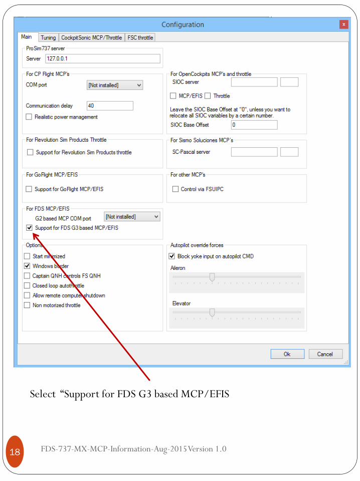
FDS-737-MX-MCP-Information-Aug-2015 Version 1.0 18
Select “Support for FDS G3 based MCP/EFIS
FDS-737-MX-MCP-Information-Aug-2015 Version 1.0 19
PMDG Software
Information to Follow
Left Intentionally Blank
FDS-737-MX-MCP-Information-Aug-2015 Version 1.0 20
iFly Software
Information to Follow
Left Intentionally Blank