FDM Tutorial 3 -...
16
FDM Tutorial 3.0 The PRL has two Fused Deposition Modeling (FDM) Machines for three- dimensional prototyping. These machines build up the form of a given 3D CAD file in successive layers, extruding molten material like a CNC glue gun. They are very useful for prototyping parts that will be CNC milled, for building plastic parts that are un-machinable, and for creating plastic or wax part patterns to be investment cast in metal. Because these machines are very valuable and their controllers are intricate, we require that students make an FDM License (shown actual size at right) before they use the machines for their own projects. This tutorial will guide you through the steps needed to make an FDM License or any other simple FDM part. Refer to the FDM System Documentation notebook at the machines and the TAs for additional help. Here are the PRL’s two FDM machines; they are very similar in operation, but they run different materials. The FDM 2000 (the machine on the left) is usually set up to run standard ABS or Investment Casting Wax (ICW), and the FDM 3000 (the machine on the right) is almost always set up to run WaterWorks ABS, which has a water-soluble support material. The FDM 2000 can also be set up to run Elastomeric Material. Please contact a TA or Craig Milroy for details concerning this option.
Transcript of FDM Tutorial 3 -...
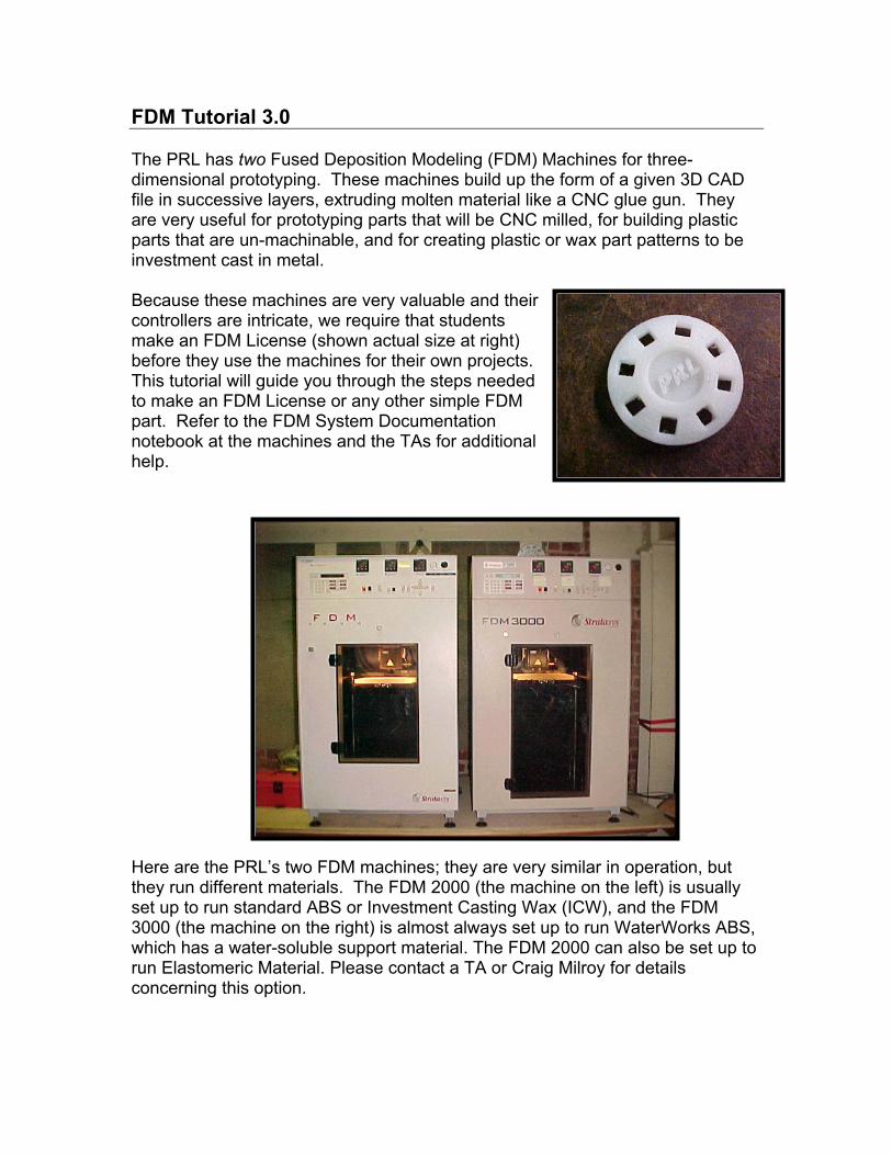
FDM Tutorial 3.0 The PRL has two Fused Deposition Modeling (FDM) Machines for three-dimensional prototyping. These machines build up the form of a given 3D CAD file in successive layers, extruding molten material like a CNC glue gun. They are very useful for prototyping parts that will be CNC milled, for building plastic parts that are un-machinable, and for creating plastic or wax part patterns to be investment cast in metal. Because these machines are very valuable and their controllers are intricate, we require that students make an FDM License (shown actual size at right) before they use the machines for their own projects. This tutorial will guide you through the steps needed to make an FDM License or any other simple FDM part. Refer to the FDM System Documentation notebook at the machines and the TAs for additional help.
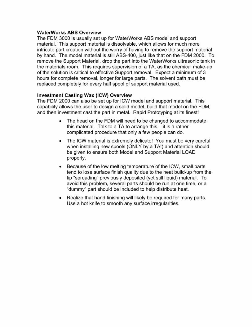
Here are the PRL’s two FDM machines; they are very similar in operation, but they run different materials. The FDM 2000 (the machine on the left) is usually set up to run standard ABS or Investment Casting Wax (ICW), and the FDM 3000 (the machine on the right) is almost always set up to run WaterWorks ABS, which has a water-soluble support material. The FDM 2000 can also be set up to run Elastomeric Material. Please contact a TA or Craig Milroy for details concerning this option.
WaterWorks ABS Overview The FDM 3000 is usually set up for WaterWorks ABS model and support material. This support material is dissolvable, which allows for much more intricate part creation without the worry of having to remove the support material by hand. The model material is still ABS-400, just like that on the FDM 2000. To remove the Support Material, drop the part into the WaterWorks ultrasonic tank in the materials room. This requires supervision of a TA, as the chemical make-up of the solution is critical to effective Support removal. Expect a minimum of 3 hours for complete removal, longer for large parts. The solvent bath must be replaced completely for every half spool of support material used. Investment Casting Wax (ICW) Overview The FDM 2000 can also be set up for ICW model and support material. This capability allows the user to design a solid model, build that model on the FDM, and then investment cast the part in metal. Rapid Prototyping at its finest!
• The head on the FDM will need to be changed to accommodate this material. Talk to a TA to arrange this – it is a rather complicated procedure that only a few people can do.
• The ICW material is extremely delicate! You must be very careful when installing new spools (ONLY by a TA!) and attention should be given to ensure both Model and Support Material LOAD properly.
• Because of the low melting temperature of the ICW, small parts tend to lose surface finish quality due to the heat build-up from the tip “spreading” previously deposited (yet still liquid) material. To avoid this problem, several parts should be run at one time, or a “dummy” part should be included to help distribute heat.
• Realize that hand finishing will likely be required for many parts. Use a hot knife to smooth any surface irregularities.
How to Create a Part on the FDM Make Your Solid Model (STL) Use Solid Edge to build a 3D model of your part and save the file as an STL. If you are doing your FDM license, you should use the FDM_key_license.STL file in the FDM_user folder instead of making your own STL. Create your own sub-folder in the FDM_user folder on the Users drive, and put the STL file that you want to build into this folder so you can access it from the FDM computers. Login to FDM Computer From the machine shop, have a TA log you on to the appropriate FDM computer as FDM_user. The FDM computers are located to the right of the FDM machines; each computer is labeled to show which machine it controls. Warm-up FDM: Set Material Temperatures Set the temperatures on your intended machine’s temperature controllers to the correct values as described below. The FDM should already be on, and its front door should be closed and latched. The temperature controllers are located at the top front of the machines. The green number is the current temperature of the item (model, support, or envelope) in degrees Celsius. The red number is the temperature that the machine is currently set to maintain. Change the set temperature by using the increase decrease buttons on each controller. Note that it is important to use the correct temperatures or the material will not behave properly.
Standard ABS on the FDM 2000:
Material Temperatures Model: 270°
Support: 265° Envelope: 70°
WaterWorks ABS on the FDM 3000:
Material Temperatures Model: 270°
Support: 233° Envelope: 70°
Note: The FDM 3000 has a “Low Temp Set” feature that reduces the support material temperature to 210° upon start-up and after program execution. BEWARE! To override, press the ENTER key on the keypad before and after running a program. This will provide enough time for the support material to come to temperature before running the part. You should never run a part at low temp setting or before the material has gotten up to temperature! Doing so would destroy the FDM tip.
Investment Casting Wax (ICW) on the FDM 2000: Material Temperatures
Model: 71° Support: 73°
Envelope: 43°
E-20 Elastomer on the FDM 2000: Material Temperatures
Model: 160° Support: 220° Envelope: 55°
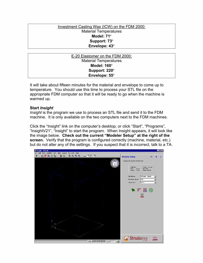
It will take about fifteen minutes for the material and envelope to come up to temperature. You should use this time to process your STL file on the appropriate FDM computer so that it will be ready to go when the machine is warmed up. Start Insight Insight is the program we use to process an STL file and send it to the FDM machine. It is only available on the two computers next to the FDM machines. Click the “Insight” link on the computer’s desktop, or click “Start”, “Programs”, “InsightV21”, “Insight” to start the program. When Insight appears, it will look like the image below. Check out the current “Modeler Setup” at the right of the screen. Verify that the program is configured correctly (machine, material, etc.) but do not alter any of the settings. If you suspect that it is incorrect, talk to a TA.
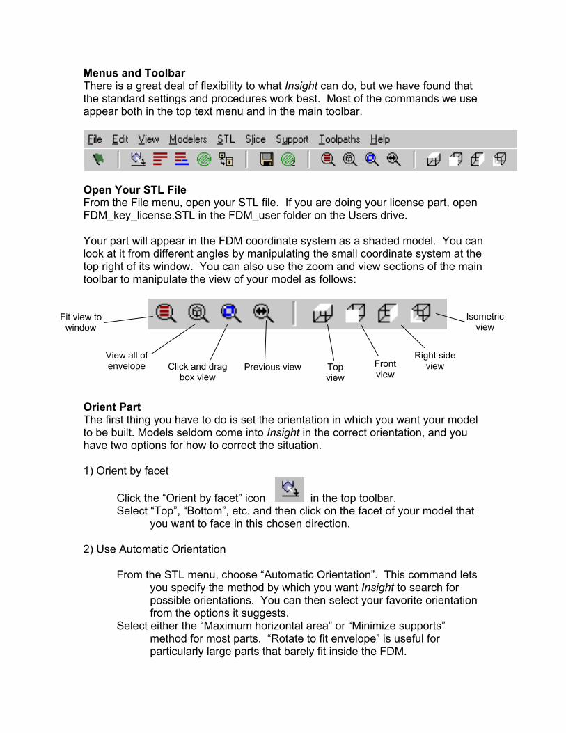
Menus and Toolbar There is a great deal of flexibility to what Insight can do, but we have found that the standard settings and procedures work best. Most of the commands we use appear both in the top text menu and in the main toolbar.
Open Your STL File From the File menu, open your STL file. If you are doing your license part, open FDM_key_license.STL in the FDM_user folder on the Users drive. Your part will appear in the FDM coordinate system as a shaded model. You can look at it from different angles by manipulating the small coordinate system at the top right of its window. You can also use the zoom and view sections of the main toolbar to manipulate the view of your model as follows:
Fit view to
window Isometric
view
View all of
envelope Right side
view Front view
Click and drag box view
Previous view
Top view
Orient Part The first thing you have to do is set the orientation in which you want your model to be built. Models seldom come into Insight in the correct orientation, and you have two options for how to correct the situation. 1) Orient by facet
Click the “Orient by facet” icon in the top toolbar. Select “Top”, “Bottom”, etc. and then click on the facet of your model that
you want to face in this chosen direction. 2) Use Automatic Orientation
From the STL menu, choose “Automatic Orientation”. This command lets
you specify the method by which you want Insight to search for possible orientations. You can then select your favorite orientation from the options it suggests.
Select either the “Maximum horizontal area” or “Minimize supports” method for most parts. “Rotate to fit envelope” is useful for particularly large parts that barely fit inside the FDM.
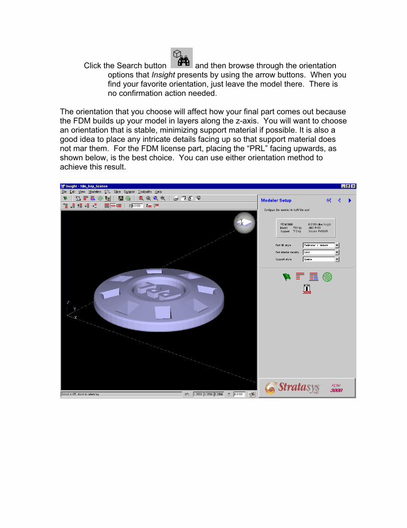
Click the Search button and then browse through the orientation options that Insight presents by using the arrow buttons. When you find your favorite orientation, just leave the model there. There is no confirmation action needed.
The orientation that you choose will affect how your final part comes out because the FDM builds up your model in layers along the z-axis. You will want to choose an orientation that is stable, minimizing support material if possible. It is also a good idea to place any intricate details facing up so that support material does not mar them. For the FDM license part, placing the “PRL” facing upwards, as shown below, is the best choice. You can use either orientation method to achieve this result.
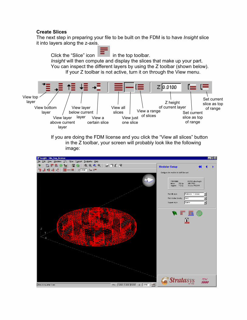
Create Slices The next step in preparing your file to be built on the FDM is to have Insight slice it into layers along the z-axis.
Click the “Slice” icon in the top toolbar. Insight will then compute and display the slices that make up your part. You can inspect the different layers by using the Z toolbar (shown below).
If your Z toolbar is not active, turn it on through the View menu.
you are doing the FDM license and you click the “View all slices” button
View top layer Z height
of current layer
View all slices
View just one slice
View a range of slices
Set current slice as top
of range
Set current slice as top
of range
View layer above current
layer
View layer below current
layer View a certain slice
View bottom layer
Ifin the Z toolbar, your screen will probably look like the following image:
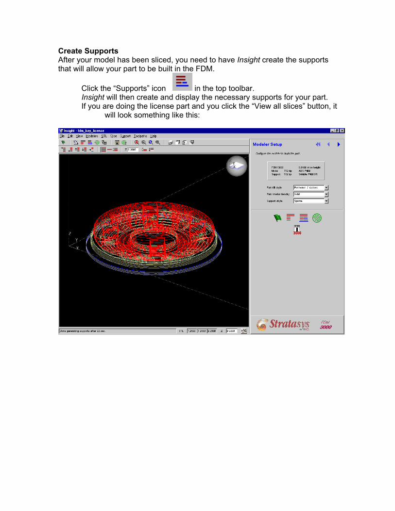
Create Supports After your model has been sliced, you need to have Insight create the supports that will allow your part to be built in the FDM.
Click the “Supports” icon in the top toolbar. Insight will then create and display the necessary supports for your part. If you are doing the license part and you click the “View all slices” button, it
will look something like this:
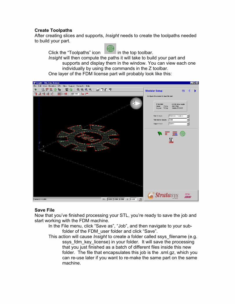
Create Toolpaths After creating slices and supports, Insight needs to create the toolpaths needed to build your part.
Click the “Toolpaths” icon in the top toolbar. Insight will then compute the paths it will take to build your part and
supports and display them in the window. You can view each one individually by using the commands in the Z toolbar.
One layer of the FDM license part will probably look like this:
Save File Now that you’ve finished processing your STL, you’re ready to save the job and start working with the FDM machine.
In the File menu, click “Save as”, “Job”, and then navigate to your sub-folder of the FDM_user folder and click “Save”.
This action will cause Insight to create a folder called ssys_filename (e.g. ssys_fdm_key_license) in your folder. It will save the processing that you just finished as a batch of different files inside this new folder. The file that encapsulates this job is the .sml.gz, which you can re-use later if you want to re-make the same part on the same machine.
Check FDM Temperatures
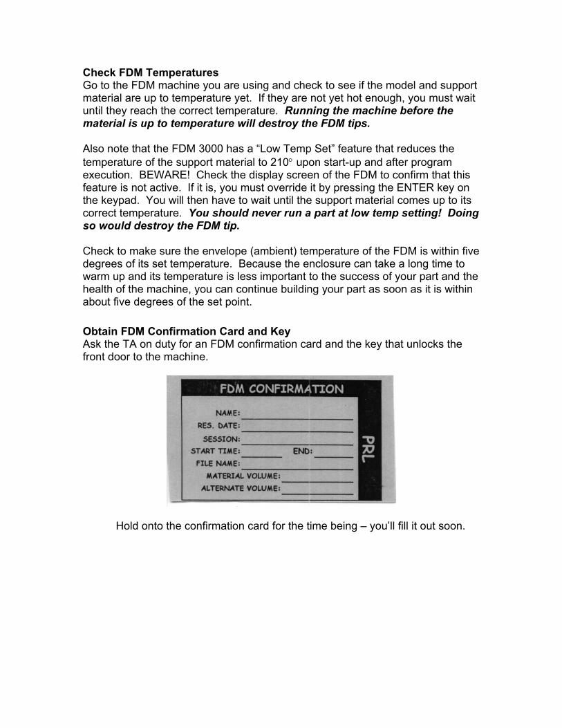
emperature yet. If they are not yet hot enough, you must wait until they reach the correct temperature. Running the machine before the materi Also note thatemperature o rogram execut rm that this feature is not active. If it is, you must override it by pressing the ENTER key on the keypad. You will then have to wait until the support material comes up to its correct temperature. You should never run a part at low temp setting! Doing so would destroy the FDM tip. Check to make sure the envelope (ambient) temperature of the FDM is within five degrees of its set temperature. Because the enclosure can take a long time to warm up and its temperature is less important to the success of your part and the health of the machine, you can continue building your part as soon as it is within about five degrees of the set point. Obtain FDM Confirmation Card and Key Ask the TA on duty for an FDM confirmation card and the key that unlocks the front door to the machine.
Go to the FDM machine you are using and check to see if the model and supportmaterial are up to t
al is up to temperature will destroy the FDM tips.
t the FDM 3000 has a “Low Temp Set” feature that reduces the f the support material to 210° upon start-up and after p
ion. BEWARE! Check the display screen of the FDM to confi
Hold onto the confirmation card for the time being – you’ll fill it out soon.
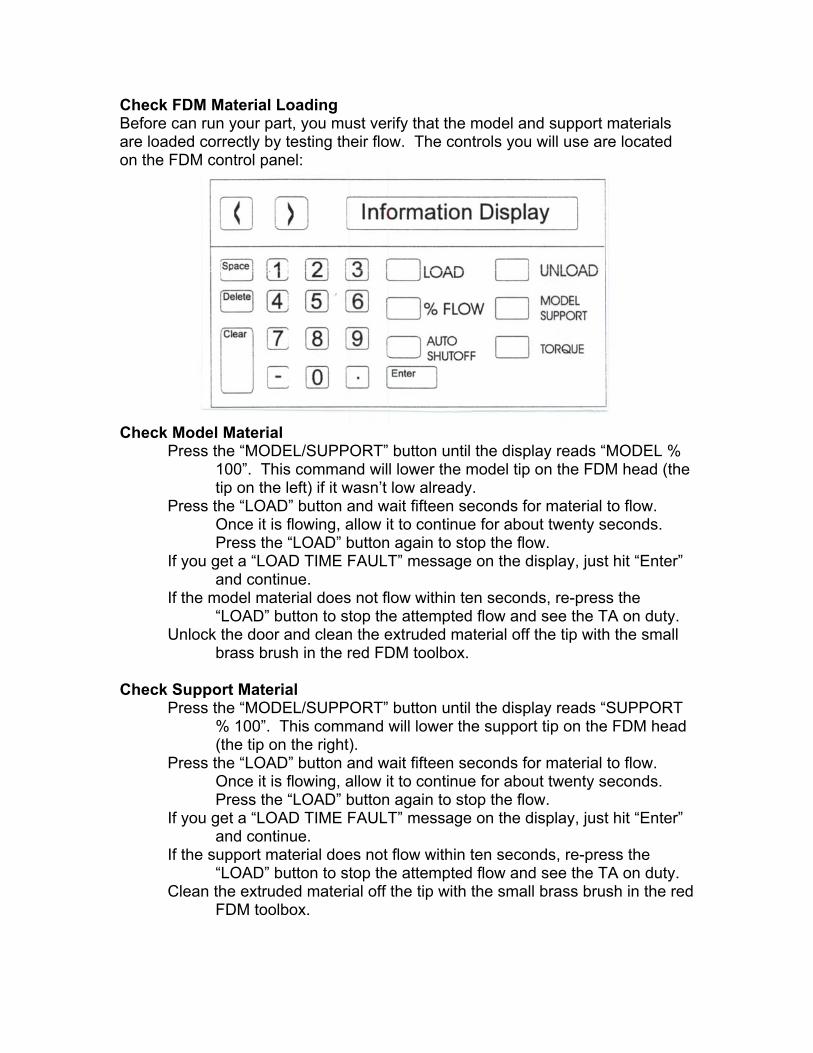
Check FDM Material Loading Before can run your part, you must verify that the model and support materials are loaded correctly by testing their flow. The controls you will use are located on the FDM control panel:
Check Model Material
Press the “MODEL/SUPPORT” button until the display reads “MODEL % 100”. This command will lower the model tip on the FDM head (the tip on the left) if it wasn’t low already.
Press the “LOAD” button and wait fifteen seconds for material to flow. Once it is flowing, allow it to continue for about twenty seconds. Press the “LOAD” button again to stop the flow.
If you get a “LOAD TIME FAULT” message on the display, just hit “Enter” and continue.
If the model material does not flow within ten seconds, re-press the “LOAD” button to stop the attempted flow and see the TA on duty.
Unlock the door and clean the extruded material off the tip with the small brass brush in the red FDM toolbox.
Check Support Material
Press the “MODEL/SUPPORT” button until the display reads “SUPPORT % 100”. This command will lower the support tip on the FDM head (the tip on the right).
Press the “LOAD” button and wait fifteen seconds for material to flow. Once it is flowing, allow it to continue for about twenty seconds. Press the “LOAD” button again to stop the flow.
If you get a “LOAD TIME FAULT” message on the display, just hit “Enter” and continue.
If the support material does not flow within ten seconds, re-press the “LOAD” button to stop the attempted flow and see the TA on duty.
Clean the extruded material off the tip with the small brass brush in the red FDM toolbox.
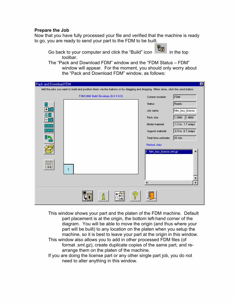
Prepare the Job Now that you have fully processed your file and verified that the machine is ready to go, you are ready to send your part to the FDM to be built.
Go back to your computer and click the “Build” icon in the top toolbar.
ut The “Pack and Download FDM” window and the “FDM Status – FDM”
window will appear. For the moment, you should only worry abothe “Pack and Download FDM” window, as follows:
This window shows your part and the platen of the FDM machine. Default
diagram. You will be able to move the origin (and thus where your part will be built) to any location on the platen when you setup the machine, so it is best to leave your part at the origin in this window.
This window also allows you to add in other processed FDM files (of format .sml.gz), create duplicate copies of the same part, and re-arrange them on the platen of the machine.
If you are doing the license part or any other single part job, you do not need to alter anything in this window.
part placement is at the origin, the bottom left-hand corner of the
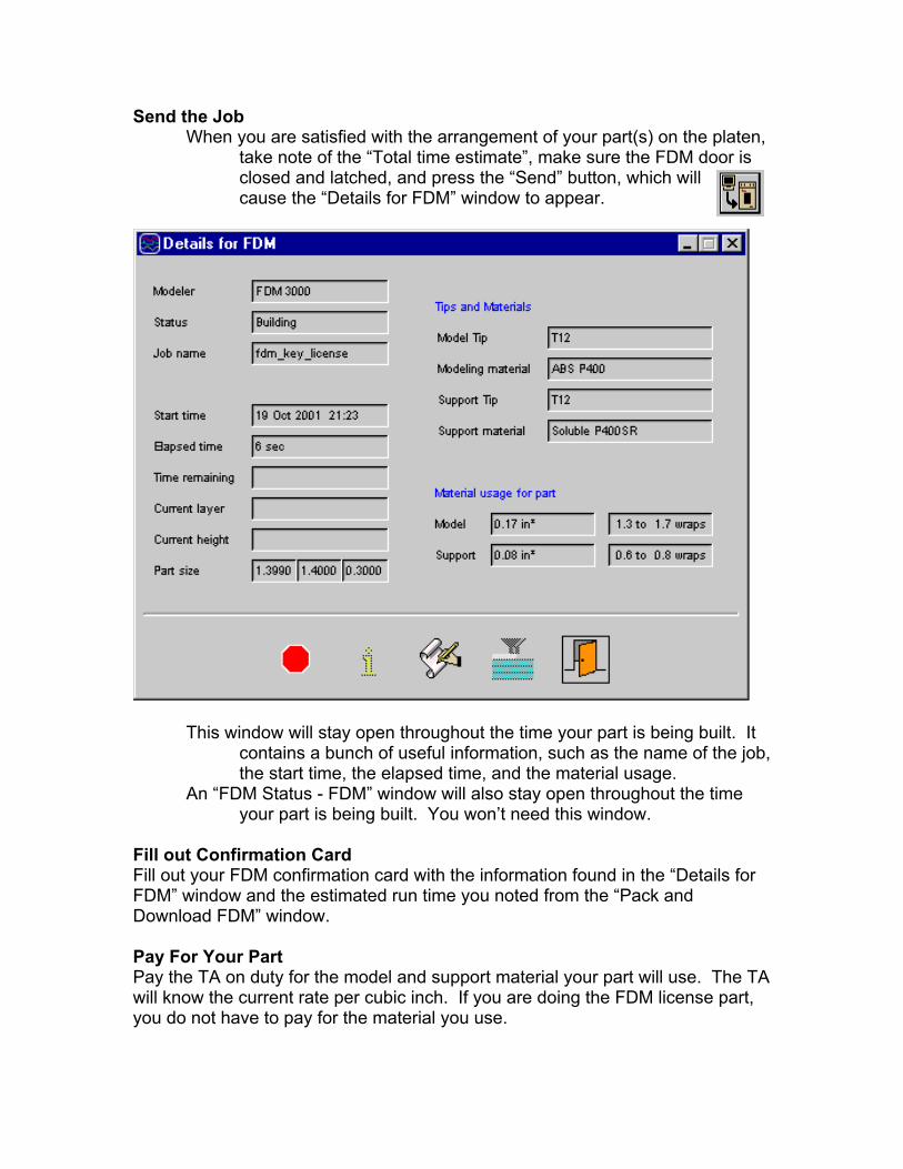
Send the Job When you are satisfied with the arrangement of your part(s) on the platen
take note of the “Total time estimate”, make sure the FDM door is closed and lat
,
ched, and press the “Send” button, which will cause the “Details for FDM” window to appear.
indow will stay open throughout the tim
This w e your part is being built. It contains a bunch of useful information, such as the name of the job,
, the elapsed time, and the material usage.
Fill ouFill out your F r FDM” Downl Pay FoPay thwill knoyou do not have to pay for the material you use.
the start timeAn “FDM Status - FDM” window will also stay open throughout the time
your part is being built. You won’t need this window.
t Confirmation Card DM confirmation card with the information found in the “Details fo
window and the estimated run time you noted from the “Pack and oad FDM” window.
r Your Part e TA on duty for the model and support material your part will use. The TA w the current rate per cubic inch. If you are doing the FDM license part,
Run FDM Calibration Sequence
e FDM run a calibration sequence to find its default origin.
Press e” button, which will turn off the flashing pause light.
The FDner of the
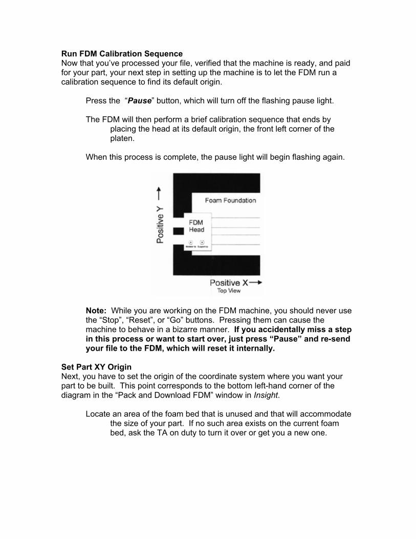
platen. When this process is complete, the pause light will begin flashing again.
Now that you’ve processed your file, verified that the machine is ready, and paid for your part, your next step in setting up the machine is to let th
the “Paus
M will then perform a brief calibration sequence that ends by
placing the head at its default origin, the front left cor
Note: While you are working on the FDM machine, you should never use the “Stop”, “Reset”, or “Go” buttons. Pressing them can cause the machine to behave in a bizarre manner. If you accidentally miss a step in this process or want to start over, just press “Pause” and re-send your file to the FDM, which will reset it internally.
et Part XY Origin
Next, ypart to be buidiagram in th
Locate
Sou have to set the origin of the coordinate system where you want your
lt. This point corresponds to the bottom left-hand corner of the e “Pack and Download FDM” window in Insight.
an area of the foam bed that is unused and that will accommodate the size of your part. If no such area exists on the current foambed, ask the TA on duty to turn it over or get you a new one.
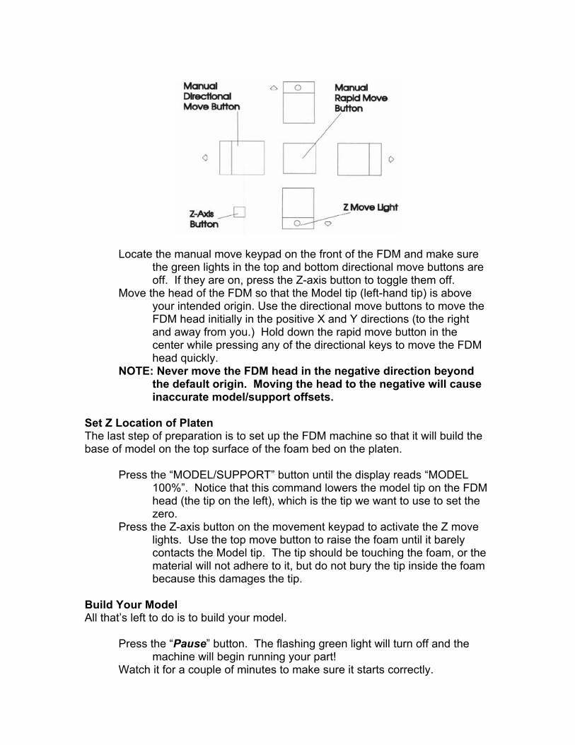
Locate the manual move keypad on the front of the FDM and make sure the green lights in the top and bottom directional move buttons are off. If they are on, press the Z-axis button to toggle them off.
Move the head of the FDM so that the Model tip (left-hand tip) is above your intended origin. Use the directional move buttons to move the FDM head initially in the positive X and Y directions (to the right and away from you.) Hold down the rapid move button in the center while pressing any of the directional keys to move the FDM head quickly.
NOTE: Never move the FDM head in the negative direction beyond the default origin. Moving the head to the negative will cause inaccurate model/support offsets.
Set Z Location of Platen The last step of preparation is to set up the FDM machine so that it will build the ase of model on the top surface of the foam bed on the platen.
Press the Z move top move button to raise the foam until it barely
e foam
t! Watch it for a couple of minutes to make sure it starts correctly.
b Press the “MODEL/SUPPORT” button until the display reads “MODEL
100%”. Notice that this command lowers the model tip on the FDM head (the tip on the left), which is the tip we want to use to set thezero. the Z-axis button on the movement keypad to activate lights. Use the contacts the Model tip. The tip should be touching the foam, or thematerial will not adhere to it, but do not bury the tip inside thbecause this damages the tip.
Build Your Model All that’s left to do is to build your model.
Press the “Pause” button. The flashing green light will turn off and the
machine will begin running your par
Post your FDM confirmation card on the front of the machine with a
your part.
ock the FDM door and return the key to the TA. it
is finished when the head stops moving and the pause light comes
Completed Part Removal
Put on gloves and pull the platen out of the FDM by rotating the lock holding it in place and sliding it straight out of the machine.
Remove your part from the foam, using a scraping tool from the red FDM toolbox if necessary.
If you used WaterWorks ABS on the FDM 300, you may be able to remove the support material by putting your part in the WaterWorks removal tank located in the Materials Room. Talk to a TA to arrange this operation.
You can remove all other support material with various hand tools. Clean Up and Shut Down
If no one is going to be using the machine immediately, lower the FDM
temperatures to the following: For ABS: For ICW:
ush located in the FDM toolbox.
urrounding area, put away all tools, and sweep the floor.
Once you have completed your license part, you are free to use the machine for your o Revision HistoryVer 1 Ver 1.1 Sep 2000 Anon P. Whodunnit Ver 1.2 Oct 2000 David and Adrian Ver 2 Nov 2000 Ryan Connolly Ver 3 Nov 2001 Katherine Kuchenbecker
magnet (NEVER with masking tape). Put the “FDM Part is Running” sign over your FDM computer monitor to
keep people from interfering withLReturn to the shop shortly after your part is due to finish. You will know
back on.
Ask the TA on duty for the FDM key to unlock the door
Model: 50° Model: 40° Support: 50° Support: 40° Envelope: 35° Envelope: 35°
Sweep out the inside of FDM machine with the paintbr
Clean up the sAsk the TA on duty to check out your machine and give you a 5-minute
shop job!
wn projects.
Dec 1999 Denise Chan