FCVC8-R INTELLIGENT MULTIFUNCTIONAL FLUSH MOUNTED …
12
Mounting and operating instructions FCVC8-R INTELLIGENT MULTIFUNCTIONAL FLUSH MOUNTED SENSOR
Transcript of FCVC8-R INTELLIGENT MULTIFUNCTIONAL FLUSH MOUNTED …

Mounting and operating instructions
FCVC8-R INTELLIGENT MULTIFUNCTIONAL FLUSH MOUNTED SENSOR

www.sentera.euMIW-FCVC8-R-EN-000 - 04 / 10 / 2019 2 - 12
Table of contents
SAFETY AND PRECAUTIONS 3
PRODUCT DESCRIPTION 4
ARTICLE CODES 4
INTENDED AREA OF USE 4
TECHNICAL DATA 4
STANDARDS 4
OPERATIONAL DIAGRAMS 5
WIRING AND CONNECTIONS 5
MOUNTING INSTRUCTIONS IN STEPS 6
OPERATING INSTRUCTIONS 8
VERIFICATION OF INSTALLATION INSTRUCTIONS 9
MODBUS REGISTER MAPS 9
TRANSPORT AND STORAGE 12
WARRANTY AND RESTRICTIONS 12
MAINTENANCE 12
FCVC8-R INTELLIGENT MULTIFUNCTIONAL FLUSH MOUNTED SENSOR

www.sentera.euMIW-FCVC8-R-EN-000 - 04 / 10 / 2019 3 - 12
back to the table of contents
SAFETY AND PRECAUTIONS
Read all the information, the datasheet, mounting and operating instructions and study the wiring and connection diagram before working with the product. For personal and equipment safety, and for optimum product performance, make sure you entirely understand the contents before installing, using, or maintaining this product.
For safety and licensing (CE) reasons, unauthorised conversion and / or modifications of the product are inadmissible.
The product should not be exposed to abnormal conditions, such as extreme temperatures, direct sunlight or vibrations. Long-term exposure to chemical vapours in high concentration can affect the product performance. Make sure the work environment is as dry as possible; avoid condensation.
All installations shall comply with local health and safety regulations and local electrical standards and approved codes. This product can only be installed by an engineer or a technician who has expert knowledge of the product and safety precautions.
Avoid contacts with energised electrical parts. Always disconnect the power supply before connecting, servicing or repairing the product.
Always verify that you apply appropriate power supply to the product and use appropriate wire size and characteristics. Make sure that all the screws and nuts are well tightened and fuses (if any) are fitted well.
Recycling of equipment and packaging should be taken into consideration and these should be disposed of in accordance with local and national legislation / regulations.
In case there are any questions that are not answered, please contact your technical support or consult a professional.
FCVC8-R INTELLIGENT MULTIFUNCTIONAL FLUSH MOUNTED SENSOR

www.sentera.euMIW-FCVC8-R-EN-000 - 04 / 10 / 2019 4 - 12
back to the table of contents
PRODUCT DESCRIPTION
The FCVC8-R series are intelligent sensors featuring adjustable temperature, relative humidity and TVOC / CO2eq ranges. Based on this TVOC measurement, an equivalent CO2 level (CO2eq) is calculated. The TVOC concentration is an accurate indicator for indoor air quality. Based on the temperature and relative humidity measurements, the dew point is calculated. The used algorithm controls a single analogue / modulating output based on the measured T, rH and TVOC values, which can be used to directly control an EC fan or an actuator powered damper. All parameters are accessible via Modbus RTU.
ARTICLE CODES
Article code Supply Maximum power
consumptionNominal power
consumption Imax
FCVC8-R 85—264 VAC / 50—60 Hz 0,76 W 0,63 W 30 mA
INTENDED AREA OF USE ■ Ventilation based on temperature, relative humidity and TVOC levels for indoor applications
■ Demand controlled ventilation ■ For indoor use only
TECHNICAL DATA
■ Demand controlled ventilation, based on T, rH and TVOC ■ Analogue / modulating output type:
► 0—10 VDC mode: min. load 50 kΩ (RL ≥ 50 kΩ) ► 0—20 mA: max. load 500 Ω (RL ≤ 500 Ω) ► PWM (open-collector type): PWM Frequency: 1 kHz, min. load 50 kΩ (RL ≥ 50 kΩ); PWM voltage level 3,3 or 12 VDC
■ Selectable temperature range: 0—50 °C ■ Selectable relative humidity range: 0—100 % ■ Selectable TVOC range: 0—60.000 ppb ■ Replaceable TVOC / CO2eq sensor element ■ 3 LEDs with adjustable light intensity for status indication ■ Accuracy: ±0,4 °C (range 0—50 °C); ±3 % rH (range 0—95 % rH); ±30 ppb TVOC (range 0—60.000 ppb)
■ Inset or surface mounting ■ Enclosure:
► internal: plastic RABS, black ► external: ABS, white ► cover: ASA, white
■ Protection standard: IP30 (according to EN 60529) ■ Typical field of use:
► temperature: 0—50 °C ► rel. humidity: 0—95 % rH, (non-condensing)
■ Storage temperature: -10—60 °C
STANDARDS
► Low Voltage Directive 2014/35/EC; ► EN 60529:1991 Degrees of protection provided by enclosures (IP Code) Amendment AC:1993 to EN 60529
► EN 60730-1:2011 Automatic electrical controls for household and similar use -
FCVC8-R INTELLIGENT MULTIFUNCTIONAL FLUSH MOUNTED SENSOR

www.sentera.euMIW-FCVC8-R-EN-000 - 04 / 10 / 2019 5 - 12
back to the table of contents
Part 1: General requirements ■ EMC Directive 2014/30/EC;
► EN 60730-1:2011 Automatic electrical controls for household and similar use - Part 1: General requirements
► EN 61000-6-1:2007 Electromagnetic compatibility (EMC) - Part 6-1: Generic standards - Immunity for residential, commercial and light industrial environments EN 61000-6-3:2007 Electromagnetic compatibility (EMC) - Part 6-3: Generic standards - Emission standard for residential, commercial and light-industrial environments Amendments A1:2011 and AC:2012 to EN 61000-6-3
► EN 61326-1:2013 Electrical equipment for measurement, control and laboratory use - EMC requirements - Part 1: General requirements
► EN 61326-2-3:2013 Electrical equipment for measurement, control and laboratory use - EMC requirements - Part 2-3: Particular requirements - Test configuration, operational conditions and performance criteria
■ WEEE 2012/19/EC ■ RoHs Directive 2011/65/EC
OPERATIONAL DIAGRAMS
AO1, max range
AO1, min range
60
40
100
0
rH Min range
-30
00 TVOC Min range TVOC Max range
Max
Min
T Min range
T Max range
rH Max range
AO1 [%]
70
10060.000
rH [%]T [°C] TVOC [ppb]
CAUTIONThe output changes automatically depending on the highest T, rH or TVOC values, i.e. the highest of the three output values controls the output. See the green line in the operational diagram above.
NOTEThe replaceable sensor element measures TVOC. Based on this TVOC value, a CO2 equivalent is calculated. However, CO2eq value cannot be used to control the output.
WIRING AND CONNECTIONS
L Power supply, line (85—264 VAC / 50—60 Hz)
N Power supply, neutral
Ao Analogue / modulating output - T, rH or TVOC (0—10 VDC / 0—20 mA / PWM)
GND Ground AO
A Modbus RTU (RS485), signal A
/B Modbus RTU (RS485), signal /B
Connections Spring contact terminal block, cable cross section: 2,5 mm2; pitch 5 mm; shielded cable
FCVC8-R INTELLIGENT MULTIFUNCTIONAL FLUSH MOUNTED SENSOR

www.sentera.euMIW-FCVC8-R-EN-000 - 04 / 10 / 2019 6 - 12
back to the table of contents
MOUNTING INSTRUCTIONS IN STEPS
Before you start mounting the unit, read carefully “Safety and Precautions”. Proceed with the following steps:
ATTENTION When planning the installation, allow enough clearance for maintenance and service. Mount the sensor in a well-ventilated area.
Inset mounting
1. Disconnect the supply voltage.2. Remove the cover of the enclosure and take the controller out of the housing, so
that it can be easily connected. 3. Do the wiring according to the wiring diagram (see Fig. 1).
Fig. 1 Wiring and connections
Power supply 85—264 VAC / 50—60 Hz
Modbus RTU
/BA
Analogue / modulating output
4. Mount the internal enclosure into the wall using appropriate connecting elements (not included in the set). Mind the correct position and mounting dimensions shown in Fig. 2 and Fig. 3.
Fig. 2 Mounting dimensions - inset mounting Fig. 3 Mounting position
3815
58
82
82
89
7658
5852
Correct Incorrect
Position at min. 1,5 m from the floor
5. Put back the frame cover of the enclosure.6. Switch on the power supply.7. Customise the factory settings to the desired ones via the 3SModbus software
or the Sensistant configurator. For the default factory settings, see Modbus register maps below.
FCVC8-R INTELLIGENT MULTIFUNCTIONAL FLUSH MOUNTED SENSOR

www.sentera.euMIW-FCVC8-R-EN-000 - 04 / 10 / 2019 7 - 12
back to the table of contents
Position at min. 1,5 m from the floor
For surface mounting1. Disconnect the power supply.2. Remove the frame cover of the enclosure.3. Take out the internal enclosure.4. Mount the external enclosure onto the wall using the dowels and screws included
in the set. Mind the correct position and mounting dimensions shown in Fig. 4 and Fig. 5.
5. Insert the connecting cables through the grommets of the unit.
Fig. 4 Mounting dimensions - surface mounting Fig. 5 Mounting position
3815
58
82
82
89
7658
5852
58
38
58
15
Correct Incorrect
6. Do the wiring according to the wiring diagram (see Fig. 1) using the information from section “Wiring and connections”.
7. Put the internal enclosure into the external one and fix it using the delivered screws and washers. (Fig. 4).
8. Put back the frame cover of the enclosure.9. Switch on the power supply.10. Customise the factory settings to the desired ones via the 3SModbus software
or the Sensistant configurator. For the default factory settings, see Modbus register maps below.
Optional settingsTo assure correct communication, the NBT needs to be activated in only two devices on the Modbus RTU network. If necessary, enable the NBT resistor via 3SModbus or Sensistant (Holding register 9).
Example 1 Example 2
RX
ТX
NBT
NBT
NBT
Slave 2Master
Slave n
Slave 1
Slave 2Slave 1
RX
ТX
NBT
NBT
Master
Slave n
NOTE On a Modbus RTU network, two bus terminators (NBTs) need to be activated.
NOTE Mount the unit so that the terminal block and connections are at the lower side.
FCVC8-R INTELLIGENT MULTIFUNCTIONAL FLUSH MOUNTED SENSOR
www.sentera.euMIW-FCVC8-R-EN-000 - 04 / 10 / 2019 8 - 12
back to the table of contents
ATTENTION Do not expose to direct sunlight!
NOTEThe sensor is not designed, manufactured or intended for control or monitoring equipment in environments requiring life safety performance, in which the failure of the sensor could lead directly to death, personal injury, or severe physical or environmental damage.
OPERATING INSTRUCTIONS
The unit is supplied with electrical energy at voltages high enough to inflict personal injury or threat to health.
ATTENTION
NOTEThe compounds released from plastics may influence the sensor readings. Please allow several days for the sensor to stabilize before you obtain the accurate values.
Calibration procedure:Sensor calibration is not necessary. All sensor elements are calibrated and tested in our factory.In the unlikely event of TVOC / CO2eq sensor element failure, this component can be replaced.
BootloaderThanks to the bootloader functionality, the unit firmware can be updated via Modbus RTU communication. With 3SM boot Application (part of 3SM center software suite), ‘boot mode’ is automatically activated and the firmware can be updated.
NOTE Make sure the power supply does not get interrupted during “bootload” procedure, otherwise you risk losing unsaved data.
LED indications
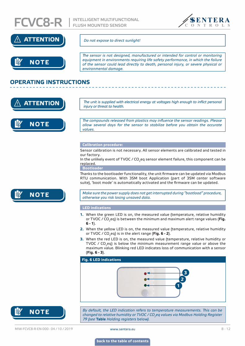
1. When the green LED is on, the measured value (temperature, relative humidity or TVOC / CO2eq) is between the minimum and maximum alert range values (Fig. 6 - 1).
2. When the yellow LED is on, the measured value (temperature, relative humidity or TVOC / CO2eq) is in the alert range (Fig. 6 - 2).
3. When the red LED is on, the measured value (temperature, relative humidity or TVOC / CO2eq) is below the minimum measurement range value or above the maximum value. Blinking red LED indicates loss of communication with a sensor (Fig. 6 - 3).
Fig. 6 LED indications
32
1
NOTE By default, the LED indication refers to temperature measurements. This can be changed to relative humidity or TVOC / CO2eq values via Modbus Holding Register 79 (see Table Holding registers below).
FCVC8-R INTELLIGENT MULTIFUNCTIONAL FLUSH MOUNTED SENSOR

www.sentera.euMIW-FCVC8-R-EN-000 - 04 / 10 / 2019 9 - 12
back to the table of contents
Ambient light sensor
The measured light intensity in lux is available in Input Register 41. Additionally, an active and standby level can be defined in Holding registers 35 and 36. Input Register 42 indicates if the measured value is below standby level, above active level or in between both levels:
■ Ambient light level < standby level: Input Register 42 indicates “Standby”. ■ Ambient light level > active level: Input Register 42 indicates “Active”. ■ Standby level < Ambient light level < Active level: Input Register 42 indicates “Low intensity”.
VERIFICATION OF INSTALLATION INSTRUCTIONS
After switching on the power supply one of the LEDs lights up according to the status of the measured variable. If this is not the case, check the connections.
MODBUS REGISTER MAPS
INPUT REGISTERS
Data type Description Data Values
1 Temperature reading signed int Actual temperature level -300—700 500 = 50,0°C
2 Temperature output value unsigned int Output value according to temperature 0—1.000 0 = 0 %
1.000 = 100 %
3 Temperature alert flag unsigned int
Flag indicates that measured Temperature is outside set alert values. Set to '1' when the measured value is outside the Temperature alert values defined by holding registers 13 and 14
0—1 0 = Temperature measurement OK 1 = Temperature measurement too low/high
4 Temperature range limit flag unsigned int
Flag indicates that measured temperature is outside set range limit values. Set to '1' when the measured temperature is outside limit range values defined by holding registers 11 and 12
0—1 0 = Temperature range OK 1 = Temperature range too low/high
5 Temperature sensor state unsigned int Flag that shows if the communication with
temperature sensor is lost 0—1 0 = OK 1 = Fault
6—9 Reserved, return 0
10 Relative humidity level unsigned int Actual relative humidity level 0—1.000 1.000 = 100,0 % rH
11 Relative humidity output value unsigned int Output value according to relative humidity 0—1.000 0 = 0%
1.000 = 100,0 %
12 Relative humidity alert flag unsigned int
Flag indicates that measured Relative humidity is outside set alert values. Set to '1' when the measured value is outside the Relative humidity alert values defined by holding registers 21 and 22
0—1 0 = Relative humidity measurement OK 1 = Relative humidity measurement too low/high
13 Relative humidity range limit flag unsigned int
Flag indicates that measured Relative humidity is outside set range limit values. Set to '1' when the measured Relative humidity is outside limit range values defined by holding registers 19 and 20
0—1 0 = Relative humidity range OK 1 = Relative humidity range too low/high
14 Humidity sensor state unsigned int Flag that shows if the communication with humidity sensor is lost 0—1 0 = OK
1 = Fault
15 Dew point level signed int Calculated dew point -700—700 200 = 20,0°C
16—20 Reserved, return 0
21 CO2eq level unsigned int Actual CO2eq level 400—60.000 1.000 = 1.000 ppm
22 CO2eq output value unsigned int Output value according to CO2eq 0—1.000 0 = 0% 1.000 = 100,0 %
23 CO2eq alert flag unsigned int
Flag indicates that measured CO2eq level is outside set alert values. Set to '1' when the measured value is outside the CO2eq values defined by holding registers 25 and 26
0—1 0 = CO2eq measurement OK 1 = CO2eq measurement too low/high
24 CO2eq range limit flag unsigned int
Flag indicates that measured CO2eq is outside set range limit values. Set to '1' when the measured CO2eq is outside limit range values set defined by holding registers 23 and 24
0—1 0 = CO2eq range OK 1 = CO2eq range too low/high
25 CO2eq Sensor state unsigned int Flag that shows if the communication with the CO2eq sensor is lost 0—1 0 = OK
1 = Fault
26 TVOC level unsigned int TVOC level 0—60.000 1000 = 1000 ppb
27 TVOC output value unsigned int Output value according to TVOC 0—1.000 0 = 0 % 1000 = 100 %
FCVC8-R INTELLIGENT MULTIFUNCTIONAL FLUSH MOUNTED SENSOR

www.sentera.euMIW-FCVC8-R-EN-000 - 04 / 10 / 2019 10 - 12
back to the table of contents
INPUT REGISTERS
Data type Description Data Values
28 TVOC alert flag unsigned intFlag indicates that measured TVOC level is outside set alert values. Set to ‘1’ when the measured value is outside the TVOC values defined by holding registers 33 and 34
0—1 0 = TVOC measurement OK 1 = TVOC measurement too low/high
29 TVOC range limit flag unsigned intFlag indicates that measured TVOC is outside set range limit values. Set to ‘1’ when the measured NO2 is outside limit range values set defined by holding registers 31 and 32
0—1 0 = TVOC measurement OK 1 = TVOCmeasurement too low/high
30 TVOC sensor state unsigned int Flag that shows if the communication with the TVOC sensor is lost 0—1 0 = OK
1 = Fault
31—38 Reserved, return 0
39 Actual output value unsigned int The actual output value 0—1.000 0 = 0% 1.000 = 100,0 %
40 Output control mode unsigned int The source of the output value 0—4
0 = Overwrite1 = Temperature2 = rH3 = TVOC4 = all OFF
41 Ambient light intensity unsigned int Measured ambient light intensity 0—32.000 1.000 = 1.000 lux
42 Active / Standby unsigned int
Active or Standby indication according the Active / Standby light level defined by holding registers 35 and 36. If the measured light level is between the two levels the indication is 0 (Low light intensity)
0—20 = Low light intensity 1 = Active 2 = Standby
43 Ambient light sensor state unsigned int Flag that shows if the communication with the
ambient light sensor is lost 0—1 0 = OK 1 = Fault
44—50 Reserved, return 0
HOLDING REGISTERSData type Description Data Values
1 Device slave address unsigned int Modbus device address 1—247 default: 1
2 Modbus baud rate unsigned int Modbus communication baud rate 0—6 default: 2
0 = 4.800 1 = 9.600 2 = 19.200 3 = 38.400 4 = 57.600 5 = 115.200 6 = 230.400
3 Modbus parity unsigned int Parity check mode 0— 2 default: 1
0 = 8N1 1 = 8E1 2 = 8O1
4 Device type unsigned int Device type. Read only 1661 = FCVC8-R
5 HW version unsigned int Hardware version of the device. Read only XXXX 0x0100 = HW version 1.0
6 FW version unsigned int Firmware version of the device. Read only XXXX 0x0100 = FW version 1.0
7 Reserved, returns 0
8 Modbus safety timeout unsigned int Timeout setting for no Modbus communication. After time runs out, output(s) is set to 0.
0—60 default: 0
0 = no timeout 60 = 60 minutes
9 Modbus network resistor termination (NBT) unsigned int Set device as end device of the line / or not by
connecting NBT0—1 default: 0
0 = NBT disconnected 1 = NBT connected
10 Modbus registers reset unsigned intResets Modbus Holding registers to default values. When finished this register is automatically reset to '0'
0—1 default: 0
0 = Idle 1 = Reset Modbus Registers
11 Minimum temperature range unsigned intMinimum value of temperature range, cannot be set higher than maximum temperature range minus 5°C
0—Max-50 default: 0 100 = 10,0°C
12 Maximum temperature range unsigned intMaximum value of temperature range, cannot be set less than minimum temperature range plus 5°C
Min+50—500 default: 500 500 = 50,0°C
13 Minimum temperature alert unsigned int Minimum temperature alarm valueMin. temperature range —Max. temperature alarm default: 0
500 = 50,0°C
14 Maximum temperature alert unsigned int Maximum temperature alarm valueMin. temperature alarm —Max. temperature range default: 500
500 = 50,0°C
15—18 Reserved, return 0
19 Minimum relative humidity range unsigned int
Minimum value of relative humidity range, cannot be set higher than maximum relative humidity range minus 5%
0 – (Max-50) default: 0 200 = 20,0 % rH
20 Maximum relative humidity range unsigned int
Maximum value of relative humidity range, cannot be set less than minimum relative humidity range plus 5%
(Min+50) – 1000 default: 1.000 850 = 85 % rH
21 Minimum relative humidity alert unsigned int Minimum relative humidity alarm value
Min. relative humidity range—Max. relative humidity alarm default: 0
200 = 20,0 % rH
22 Maximum relative humidity alert unsigned int Maximum relative humidity alarm value
Min. relative humidity alarm —Max. relative humidity range default: 1.000
850 = 85 % rH
23 Minimum CO2eq range unsigned int Minimum CO2eq range, cannot be set higher than maximum CO2eq range minus 10 ppm
400 – (Max-100) default: 400 100 = 100 ppm
FCVC8-R INTELLIGENT MULTIFUNCTIONAL FLUSH MOUNTED SENSOR

www.sentera.euMIW-FCVC8-R-EN-000 - 04 / 10 / 2019 11 - 12
back to the table of contents
HOLDING REGISTERSData type Description Data Values
24 Maximum CO2eq range unsigned int Maximum CO2eq range, cannot be set less than minimum CO2eq range plus 10 ppm
(Min+100) – 60.000 default: 2.000 1.000 = 1.000 ppm
25 Minimum CO2eq alert unsigned int Minimum CO2eq alarm valueMin. CO2eq range—Max. CO2eq alarm default: 400
100 = 100 ppm
26 Maximum CO2eq alert unsigned int Maximum CO2eq alarm valueMin. CO2eq alarm —Max. CO2eq range default: 2.000
100 = 100 ppm
27 Minimum TVOC range unsigned int Minimum TVOC range, cannot be set higher than maximum TVOC range minus 100 ppb
0 – (Max-100) -60.000 default: 0 1.000 = 1.000 ppb
28 Maximum TVOC range unsigned int Maximum TVOC range, cannot be set less than minimum TVOC2 range plus 10 ppm
(Min+100) – 60.000 default: 2.000 100 = 100 ppb
29 Minimum TVOC alert unsigned int Minimum TVOC alarm valueMin. TVOC range—Max. TVOC alarm default: 0
100 = 100 ppb
30 Maximum TVOC alert unsigned int Maximum TVOC alarm valueMin. TVOC alarm —Max. TVOC range default: 2.000
1.000 = 1.000 ppb
31—34 Reserved, return 0
35 Active light level unsigned int The ambient light level above which 'Active' is indicated in input register 42
0—32.000 default: 100 100 = 100 lux
36 Standby light level unsigned int The ambient light level below which 'Standby' is indicated in input register 42
0—32.000 default: 10 10 = 10 lux
37—39 Reserved, return 0
40 CO2 module self calibration unsigned intEnables or disables the CO2 module self calibration technique. If enabled it is advisable that the CO2 concentration drops to outside level (400 ppm) in a 7 day period.
0—1 default: 1
0 = Disabled 1 = Enabled
41 Output 1 type unsigned int Select analogue / modulating output 1 type 1—3 default: 1
1 = 0—10 VDC 2 = 0—20 mA 3 = PWM
42 Output 1 overwrite unsigned int Enables the direct control over the temperature output
0—1 default: 0
0 = Disabled 1 = Enabled
43 Output 1 overwrite value unsigned int Overwrite value for output 1. Active only if Holding register 42 is set to 1
0—1.000 default: 0
0 = 0 % 1.000 = 100 %
44 Internal voltage source selection Output 1 unsigned int Selection of internal voltage source for PWM
output 10—1 default: 0
0 = 3,3 VDC 1 = 12 VDC
45 Minimum output 1 value unsigned int Set minimum value of output signal in percentage 0—40 default: 0 20 = 20 %
46 Maximum output 1 value unsigned int Set maximum value of output signal in percentage 60—100 default: 100 60 = 60 %
47 Temperature sensor selection (ON/OFF) unsigned int Turn ON or OFF the temperature sensor (related
to output 1)0—1default: 1
0 = OFF1 = ON
48—56 Reserved, return 0
57 Relative humidity sensor selection (ON/OFF) unsigned int Turn ON or OFF the rH sensor (related to output 1) 0—1
default: 10 = OFF1 = ON
58—66 Reserved, return 0
67 TVOC sensor selection (ON/OFF) unsigned int Turn ON or OFF the TVOC sensor (related to
output 1)0—1default: 1
0 = OFF1 = ON
68—78 Reserved, return 0
79 LED indication unsigned int LED indication related to one of the parameters 1—3 default: 1
1= Temperature 2 = rH 3 = CO2eq 4 = TVOC
80 LED intensity / brightness unsigned int LED intensity (incrementing with step of 10 %) 0—10 default: 5
0 = OFF 1 = 10 %5 = 50 % 10 = 100 %
For more information about Modbus over serial line, please visit: http://www.modbus.org/docs/Modbus_over_serial_line_V1_02.pdf
FCVC8-R INTELLIGENT MULTIFUNCTIONAL FLUSH MOUNTED SENSOR

www.sentera.euMIW-FCVC8-R-EN-000 - 04 / 10 / 2019 12 - 12
back to the table of contents
TRANSPORT AND STORAGE
Avoid shocks and extreme conditions; stock in original packing.
WARRANTY AND RESTRICTIONS
Two years from the delivery date against defects in manufacturing. Any modifications or alterations to the product after the date of publication relieve the manufacturer of any responsibilities. The manufacturer bears no responsibility for any misprints or mistakes in this data.
MAINTENANCE
In normal conditions this product is maintenance-free. If soiled, clean with a dry or damp cloth. In case of heavy pollution, clean with a non-aggressive product. In these circumstances the unit should be disconnected from the supply. Pay attention that no fluids enter the unit. Only reconnect it to the supply when it is completely dry.
FCVC8-R INTELLIGENT MULTIFUNCTIONAL FLUSH MOUNTED SENSOR