FCS PROBE FLOW MONITOR PRODUCT OVERVIEW PROBE FLOW MONITOR PRODUCT OVERVIEW Mounting Instructions...
18
C23 B1052 www.turck.us • 1-800-544-7769 • Fax: (763) 553-0708 • TURCK Inc. Minneapolis, MN 55441 FCS PROBE FLOW MONITOR PRODUCT OVERVIEW Mounting Instructions Areas of turbulent flow occur whenever there is a change in the pipe construction (e.g. pipe inlets, pipe outlets, pipe elbows). To avoid an inaccurate output, the following guidelines should be observed: 6 LEDs for flow rate status indication: Setup – Operating and Display Functions Self Contained Insertion Probe ≥ 20 mA > 16 mA > 12 mA > 8 mA > 4 mA ≤ 4 mA Sealing screw (on front of device) covers the potentiometer. Potentiometer for the adjustment of flow switch point. With analog devices the potentiometer is used to set the measuring range. 4 x green: degree of set point overrange (1, 2, 3, or 4 green LEDs are lit) 1 x yellow: flow is at/above set point 1 x red: flow is below set point A) Pay special attention to the minimum distance (a ≥ 4xd) to tube bend and intersections. C) If a possibility of deposit build-up exists, mount the flow B) Flow monitor must be mounted from below in applications where medium does not completely fill the pipe. Proper Orientation For Self-Contained Metal Housing a a d a ≥ 4 x d Flow Flow (Low) Flow (Standard) Flow (Low) Flow (Standard) Flow (Low) Flow (Low) Flow (Standard) Flow (Standard) Proper Orientation For Self-Contained Plastic Housing Proper Orientation For Remote Insertion Probe Courtesy of Steven Engineering, Inc.-230 Ryan Way, South San Francisco, CA 94080-6370-Main Office: (650) 588-9200-Outside Local Area: (800) 258-9200-www.stevenengineering.com
Transcript of FCS PROBE FLOW MONITOR PRODUCT OVERVIEW PROBE FLOW MONITOR PRODUCT OVERVIEW Mounting Instructions...
C23 B1052 www.turck.us • 1-800-544-7769 • Fax: (763) 553-0708 • TURCK Inc. Minneapolis, MN 55441
FCS PROBE FLOW MONITORPRODUCT OVERVIEW
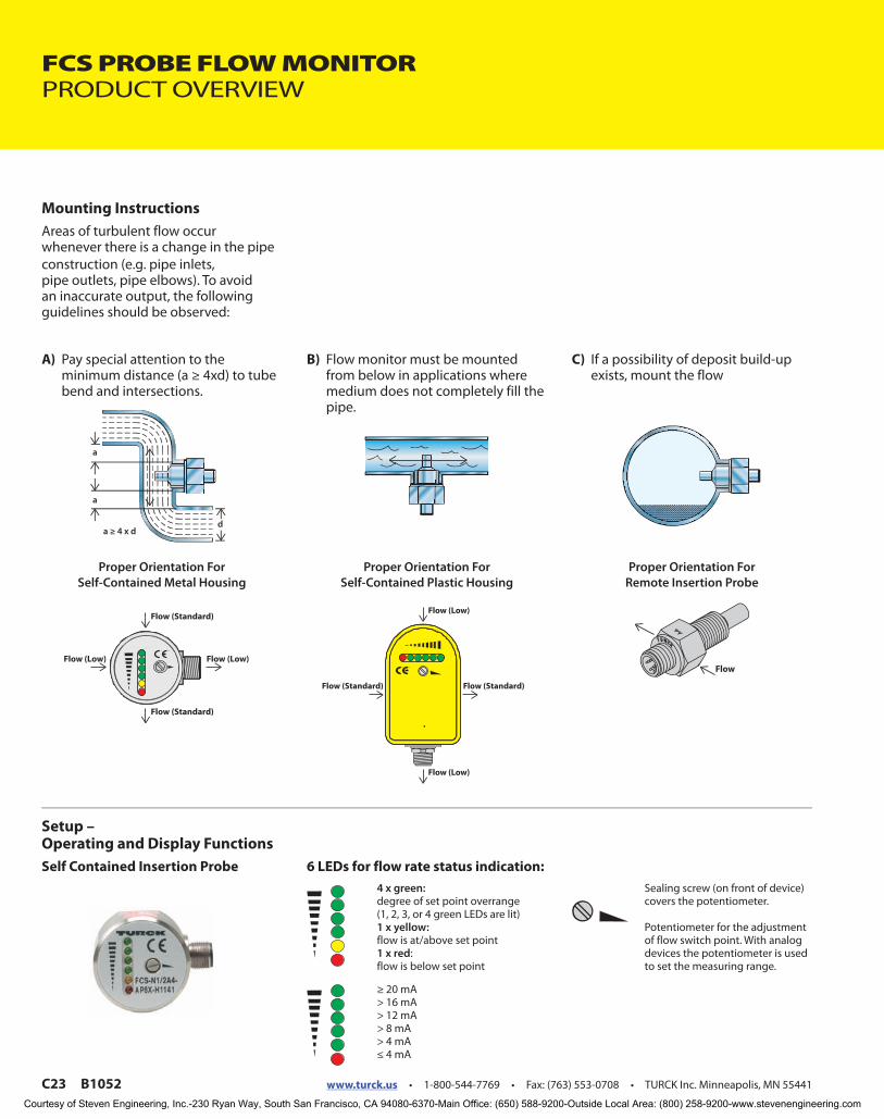
Mounting InstructionsAreas of turbulent flow occur whenever there is a change in the pipe construction (e.g. pipe inlets, pipe outlets, pipe elbows). To avoid an inaccurate output, the following guidelines should be observed:
6 LEDs for flow rate status indication:
Setup – Operating and Display FunctionsSelf Contained Insertion Probe
≥ 20 mA> 16 mA> 12 mA> 8 mA> 4 mA≤ 4 mA
Sealing screw (on front of device) covers the potentiometer.
Potentiometer for the adjustment of flow switch point. With analog devices the potentiometer is used to set the measuring range.
4 x green: degree of set point overrange (1, 2, 3, or 4 green LEDs are lit)1 x yellow: flow is at/above set point1 x red:flow is below set point
A) Pay special attention to the minimum distance (a ≥ 4xd) to tube bend and intersections.
C) If a possibility of deposit build-up exists, mount the flow
B) Flow monitor must be mounted from below in applications where medium does not completely fill the pipe.
Proper Orientation For Self-Contained Metal Housing
a
a
da ≥ 4 x d
FlowFlow (Low)
Flow (Standard)
Flow (Low)
Flow (Standard)
Flow (Low)
Flow (Low)
Flow (Standard)Flow (Standard)
Proper Orientation For Self-Contained Plastic Housing
Proper Orientation For Remote Insertion Probe
Courtesy of Steven Engineering, Inc.-230 Ryan Way, South San Francisco, CA 94080-6370-Main Office: (650) 588-9200-Outside Local Area: (800) 258-9200-www.stevenengineering.com

www.turck.us • 1-800-544-7769 • Fax: (763) 553-0708 • TURCK Inc. Minneapolis, MN 55441 B1052 C24
Flow Monitors
FL
OW
FCS = Insertion Probe Flow SensorFCTS = Flow Sensor with
Temperature Setpoint
Sensor Type
N1/2 = 1/2 NPTN3/4 = 3/4 NPTG1/4 = G1/4 (1/4 BSPP)G1/2 = G1/2 (1/2 BSPP)GL1/2 = G1/2 (1/2 BSPP with additional threading)50 = 1.5 inch Tri-clamp
Fluid Connection
2AP8X = Dual N.O. PNPAP8X = N.O. PNPAN8X = N.O. NPNARX = N.O. RelayRRX = N.C. RelayLIX = 4-20 mANA = Remote (requires MK or MS 96)NAEX = Intrinsically Safe
Circuitry
H1141 = eurofast ®
H1140 = eurofast
B1151 = minifast ®
B3141 = microfast ®
B3151 = microfast
Electrical Connection
A4 = 316 Stainless Steel Housing and ProbeA2P = 303 Stainless Steel Probe with PBT HousingA4P = 316 Stainless Steel Probe with PBT HousingAL = 303 Stainless Steel ProbeHB = Hastelloy BHC22 = Hastelloy C22T = Dyflor (PVDF)TN = Titanium w/B3 Coating
Housing
Flow Monitor Part Number Key - Insertion Probe Sensor
FCS - N1/2 A4P - AP8X - H1141 /...
/A = Airflow/L = Probe Length in mm/D100 = +120°C (+248°F)/D500 = 500 Bar rating/D014 = Tri-clamp fitting
Special Option Codes
Courtesy of Steven Engineering, Inc.-230 Ryan Way, South San Francisco, CA 94080-6370-Main Office: (650) 588-9200-Outside Local Area: (800) 258-9200-www.stevenengineering.com

C25 B1052 www.turck.us • 1-800-544-7769 • Fax: (763) 553-0708 • TURCK Inc. Minneapolis, MN 55441
TURCK
Flow Monitors
• Great for water or Oil
• IP65
• LED visualization of flow
rate
• Great for Stamping Press Lubrication
Oil Monitoring, Weld Tip Protection,
Pump Run Dry Protection, and other
monitoring applications
Probe style Flow Monitors
Part Number Flo
wD
ete
ctio
n
Ra
ng
e, W
ate
r(c
m/s
)F
low
De
tect
ion
Ra
ng
e, O
il(c
m/s
)
Op
era
tin
gV
olt
ag
e
Cu
rre
nt
Co
nsu
mp
tio
n
Flu
idC
on
ne
ctio
n
Output: Flow Pro
be
Len
gth
(mm
)
Wir
ing
Op
tio
na
l Ad
ap
ters
Dra
win
g
FCS-N1/2A4P-AP8X-H1141 5-150 10-300 24 VDC +/-10% ≤100 1/2" NPT PNP N.O. 42 2 1
FCS-N1/2A4P-LIX-H1141 5-150 N/A 24 VDC +/-10% ≤100 1/2" NPT 4-20 mA Linear Analog 42 1 3
FCS-N1/2A4P-LIX-H1141/D037 5-150 10-300 24 VDC +/-10% ≤100 1/2" NPT 4-20 mA Non-Linear Analog 42 1 3
FCS-G1/2A4P-AP8X-H1141 1-150 3-300 24 VDC +/-10% ≤60 G 1/2" PNP NO 31 2 2
FCS-N1/2A4P-AP8X-H1141/L060 1-150 3-300 24 VDC +/-10% ≤60 1/2" NPT PNP N.O. 60 2 1
FCS-N1/2A4P-AP8X-H1141/L100 1-150 3-300 24 VDC +/-10% ≤60 1/2" NPT PNP N.O. 100 2 1
FCS-N1/2A4P-AP8X-H1141/L120 1-150 3-300 24 VDC +/-10% ≤60 1/2" NPT PNP N.O. 120 2 1
FCS-N1/2A4P-ARX-B1151 115VAC 1-150 3-300 115 VAC +/-15% ≤60 1/2" NPT Relay N.O. 42 3 4
FCS-N1/2A4P-RRX-B1151 115VAC 1-150 3-300 115 VAC +/-15% ≤60 1/2" NPT Relay N.C. 42 4 4
FCS-N1/2A4P-ARX-B1151 230VAC 1-150 3-300 230 VAC +/-15% ≤30 1/2" NPT Relay N.O. 42 7 4
FCS-N1/2A4P-ARX-B1151/L060/115VAC 1-150 3-300 115 VAC +/-15% ≤60 1/2" NPT Relay N.O. 60 3 4
FCS-N1/2A4P-ARX-B1151/L080/115VAC 1-150 3-300 115 VAC +/-15% ≤60 1/2" NPT Relay N.O. 80 3 4
FCS-N1/2A4P-ARX-B1151/L100/115VAC 1-150 3-300 115 VAC +/-15% ≤60 1/2" NPT Relay N.O. 100 3 4
FCS-N1/2A4P-ARX-B1151/L120 115VAC 1-150 3-300 115 VAC +/-15% ≤60 1/2" NPT Relay N.O. 120 3 4
FCS-N1/2A4P-ARX-B1151/L160/115VAC 1-150 3-300 115 VAC +/-15% ≤60 1/2" NPT Relay N.O. 160 3 4
FCS-N1/2A4P-ARX-B3141 115VAC 1-150 3-300 115 VAC +/-15% ≤60 1/2" NPT Relay N.O. 42 5 5
FCS-N1/2A4P-ARX-B3141/L060 115VAC 1-150 3-300 115 VAC +/-15% ≤60 1/2" NPT Relay N.O. 60 5 5
FCS-N1/2A4P-ARX-B3151 115VAC 1-150 3-300 115 VAC +/-15% ≤60 1/2" NPT Relay N.O. 42 6 5
FCS-N1/2A4P-ARX-B3151/L220 115VAC 1-150 3-300 115 VAC +/-15% ≤60 1/2" NPT Relay N.O. 220 6 5
Electrical
Switching Current PNP outputs ≤400 mA
Analog Load 4-20 mA outputs ≤500ΩSwitching Current Relay Outputs ≤2A at 60 VDC
Environmental
Protection IP65
Pressure Rating 1450 PSI
Ambient Temperature -20 to 70 °C
Media Temperature -20 to 80 °C
Materials
Housing PBT
Cable Connector 303 Stainless Steel
Wetted Parts 316 Ti Stainless Steel
Operational
Time Delay before Availability 2-15 seconds 8 seconds typical
Response time 1-15 seconds, 2 seconds typical
Response time 1-13 seconds, 2 seconds typical
Maximum Temperature Change 4.2 °C/second
Specifications
Courtesy of Steven Engineering, Inc.-230 Ryan Way, South San Francisco, CA 94080-6370-Main Office: (650) 588-9200-Outside Local Area: (800) 258-9200-www.stevenengineering.com
www.turck.us • 1-800-544-7769 • Fax: (763) 553-0708 • TURCK Inc. Minneapolis, MN 55441 B1052 C26
Flow Monitors
FL
OW
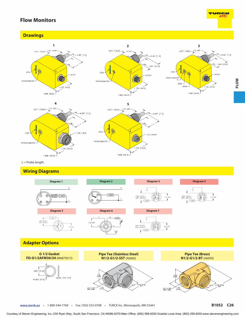
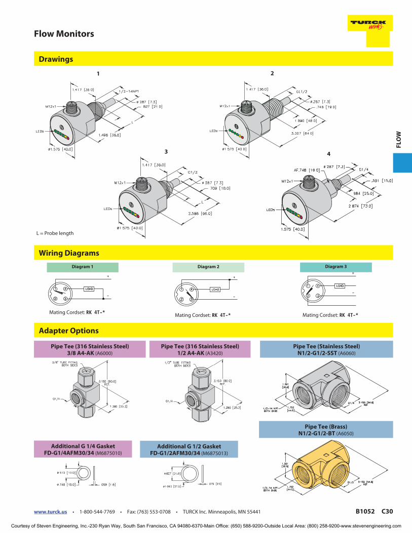
Adapter Options
Wiring Diagrams
Drawings
1 2 3
4 5
Diagram 2Diagram 1 Diagram 3 Diagram 4
Diagram 5 Diagram 6 Diagram 7
Pipe Tee (Brass)N1/2-G1/2-BT (A6050)
Pipe Tee (Stainless Steel)N1/2-G1/2-SST (A6060)
G 1/2 GasketFD-G1/2AFM30/34 (M6875013)
L = Probe length
Courtesy of Steven Engineering, Inc.-230 Ryan Way, South San Francisco, CA 94080-6370-Main Office: (650) 588-9200-Outside Local Area: (800) 258-9200-www.stevenengineering.com
C27 B1052 www.turck.us • 1-800-544-7769 • Fax: (763) 553-0708 • TURCK Inc. Minneapolis, MN 55441
TURCK
Flow Monitors
• Great for water and oil
• IP65
• LED visualization of flow rate
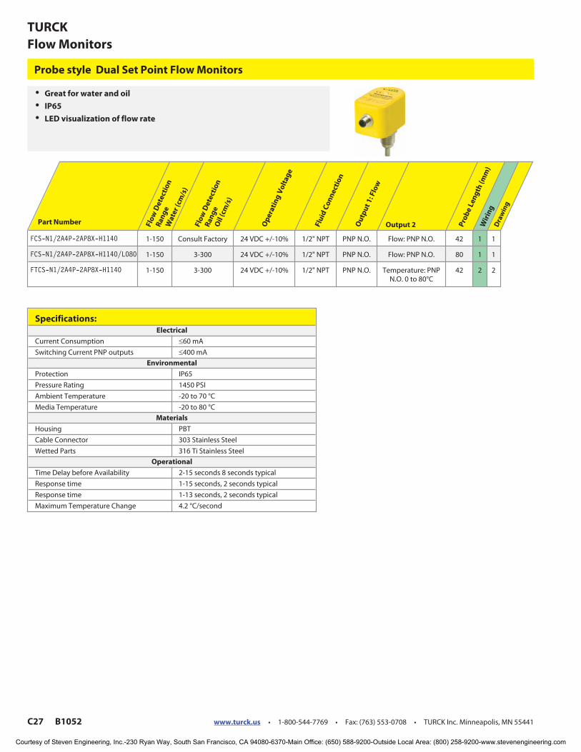
Probe style Dual Set Point Flow Monitors
Part Number Flo
wD
ete
ctio
n
Ra
ng
eW
ate
r(c
m/s
)
Flo
wD
ete
ctio
n
Ra
ng
eO
il(c
m/s
)
Op
era
tin
gV
olt
ag
e
Flu
idC
on
ne
ctio
n
Ou
tpu
t1
: Flo
w
Output 2 Pro
be
Len
gth
(mm
)W
irin
gD
raw
ing
FCS-N1/2A4P-2AP8X-H1140 1-150 Consult Factory 24 VDC +/-10% 1/2" NPT PNP N.O. Flow: PNP N.O. 42 1 1
FCS-N1/2A4P-2AP8X-H1140/L080 1-150 3-300 24 VDC +/-10% 1/2" NPT PNP N.O. Flow: PNP N.O. 80 1 1
FTCS-N1/2A4P-2AP8X-H1140 1-150 3-300 24 VDC +/-10% 1/2" NPT PNP N.O. Temperature: PNPN.O. 0 to 80°C
42 2 2
Specifications:Electrical
Current Consumption ≤60 mA
Switching Current PNP outputs ≤400 mA
Environmental
Protection IP65
Pressure Rating 1450 PSI
Ambient Temperature -20 to 70 °C
Media Temperature -20 to 80 °C
Materials
Housing PBT
Cable Connector 303 Stainless Steel
Wetted Parts 316 Ti Stainless Steel
Operational
Time Delay before Availability 2-15 seconds 8 seconds typical
Response time 1-15 seconds, 2 seconds typical
Response time 1-13 seconds, 2 seconds typical
Maximum Temperature Change 4.2 °C/second
Courtesy of Steven Engineering, Inc.-230 Ryan Way, South San Francisco, CA 94080-6370-Main Office: (650) 588-9200-Outside Local Area: (800) 258-9200-www.stevenengineering.com

www.turck.us • 1-800-544-7769 • Fax: (763) 553-0708 • TURCK Inc. Minneapolis, MN 55441 B1052 C28
Flow Monitors
FL
OW
Wiring Diagrams
Drawings
21
Diagram 1
Mating Cordset:
RK 4.4T-*
Diagram 2
Mating Cordset:
RK 4.4T-*
L = Probe length
Courtesy of Steven Engineering, Inc.-230 Ryan Way, South San Francisco, CA 94080-6370-Main Office: (650) 588-9200-Outside Local Area: (800) 258-9200-www.stevenengineering.com
C29 B1052 www.turck.us • 1-800-544-7769 • Fax: (763) 553-0708 • TURCK Inc. Minneapolis, MN 55441
TURCK
Flow Monitors
• Great for water or oil
• IP67
• LED visualization of flow rate
• Great for Stamping Press
Lubrication oil Monitoring,
Weld Tip Protection, Pump Run
Dry Protection, and other
monitoring applications
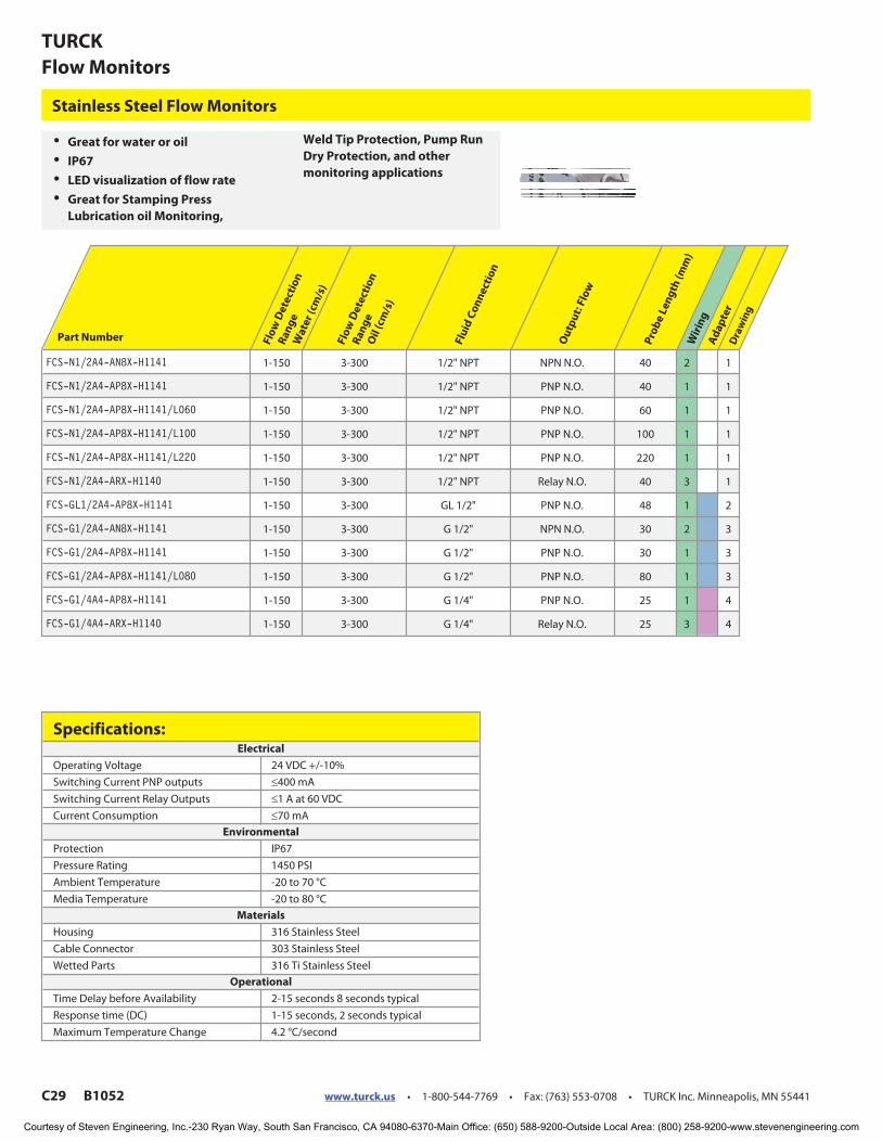
Stainless Steel Flow Monitors
Part Number Flo
wD
ete
ctio
n
Ra
ng
eW
ate
r(c
m/s
)
Flo
wD
ete
ctio
n
Ra
ng
eO
il(c
m/s
)
Flu
idC
on
ne
ctio
n
Ou
tpu
t:F
low
Pro
be
Len
gth
(mm
)W
irin
gA
da
pte
rD
raw
ing
FCS-N1/2A4-AN8X-H1141 1-150 3-300 1/2" NPT NPN N.O. 40 2 1
FCS-N1/2A4-AP8X-H1141 1-150 3-300 1/2" NPT PNP N.O. 40 1 1
FCS-N1/2A4-AP8X-H1141/L060 1-150 3-300 1/2" NPT PNP N.O. 60 1 1
FCS-N1/2A4-AP8X-H1141/L100 1-150 3-300 1/2" NPT PNP N.O. 100 1 1
FCS-N1/2A4-AP8X-H1141/L220 1-150 3-300 1/2" NPT PNP N.O. 220 1 1
FCS-N1/2A4-ARX-H1140 1-150 3-300 1/2" NPT Relay N.O. 40 3 1
FCS-GL1/2A4-AP8X-H1141 1-150 3-300 GL 1/2" PNP N.O. 48 1 2
FCS-G1/2A4-AN8X-H1141 1-150 3-300 G 1/2" NPN N.O. 30 2 3
FCS-G1/2A4-AP8X-H1141 1-150 3-300 G 1/2" PNP N.O. 30 1 3
FCS-G1/2A4-AP8X-H1141/L080 1-150 3-300 G 1/2" PNP N.O. 80 1 3
FCS-G1/4A4-AP8X-H1141 1-150 3-300 G 1/4" PNP N.O. 25 1 4
FCS-G1/4A4-ARX-H1140 1-150 3-300 G 1/4" Relay N.O. 25 3 4
Specifications:Electrical
Operating Voltage 24 VDC +/-10%
Switching Current PNP outputs ≤400 mA
Switching Current Relay Outputs ≤1 A at 60 VDC
Current Consumption ≤70 mA
Environmental
Protection IP67
Pressure Rating 1450 PSI
Ambient Temperature -20 to 70 °C
Media Temperature -20 to 80 °C
Materials
Housing 316 Stainless Steel
Cable Connector 303 Stainless Steel
Wetted Parts 316 Ti Stainless Steel
Operational
Time Delay before Availability 2-15 seconds 8 seconds typical
Response time (DC) 1-15 seconds, 2 seconds typical
Maximum Temperature Change 4.2 °C/second
Courtesy of Steven Engineering, Inc.-230 Ryan Way, South San Francisco, CA 94080-6370-Main Office: (650) 588-9200-Outside Local Area: (800) 258-9200-www.stevenengineering.com
www.turck.us • 1-800-544-7769 • Fax: (763) 553-0708 • TURCK Inc. Minneapolis, MN 55441 B1052 C30
Flow Monitors
FL
OW
Adapter Options
Wiring Diagrams
Drawings
2
3 4
1
Diagram 2
Mating Cordset: RK 4T-*
Diagram 1
Mating Cordset: RK 4T-*
Pipe Tee (316 Stainless Steel)3/8 A4-AK (A6000)
Pipe Tee (316 Stainless Steel)1/2 A4-AK (A3420)
Pipe Tee (Brass)N1/2-G1/2-BT (A6050)
Pipe Tee (Stainless Steel)N1/2-G1/2-SST (A6060)
Additional G 1/4 GasketFD-G1/4AFM30/34 (M6875010)
Additional G 1/2 GasketFD-G1/2AFM30/34 (M6875013)
Diagram 3
Mating Cordset: RK 4T-*
L = Probe length
Courtesy of Steven Engineering, Inc.-230 Ryan Way, South San Francisco, CA 94080-6370-Main Office: (650) 588-9200-Outside Local Area: (800) 258-9200-www.stevenengineering.com

C31 B1052 www.turck.us • 1-800-544-7769 • Fax: (763) 553-0708 • TURCK Inc. Minneapolis, MN 55441
TURCK
Flow Monitors
• IP67
• LED visualization of flow rate
• 3A approved for Food and
Beverage applications
Tri-clamp style Flow Monitors
Part Number Flo
wD
ete
ctio
n
Ra
ng
eW
ate
r(c
m/s
)
Flo
wD
ete
ctio
n
Ra
ng
eO
il(c
m/s
)
Flu
idC
on
ne
ctio
n
Ou
tpu
t:F
low
Pro
be
Len
gth
(mm
)W
irin
gD
raw
ing
#
FCS-50A4-AP8X-H1141/D014 1-150 3-300 1.5" tri-clamp PNP N.O. 52 1 1
FCS-64A4-AP8X-H1141/D014 1-150 3-300 2" tri-clamp PNP N.O. 52 1 2
Specifications:Electrical
Operating Voltage 24 VDC +/-10%
Switching Current PNP outputs ≤400 mA
Current Consumption ≤70 mA
Environmental
Protection IP67
Pressure Rating 1450 PSI
Ambient Temperature -20 to 80 °C
Media Temperature 0 to 80 °C; 100°C for 10 minutes without damage
Materials
Housing 316 Stainless Steel
Cable Connector 303 Stainless Steel
Wetted Parts 316 Ti Stainless Steel
Operational
Time Delay before Availability 2-15 seconds 8 seconds typical
Response time (DC) 1-15 seconds, 2 seconds typical
Maximum Temperature Change 4.2 °C/second
Courtesy of Steven Engineering, Inc.-230 Ryan Way, South San Francisco, CA 94080-6370-Main Office: (650) 588-9200-Outside Local Area: (800) 258-9200-www.stevenengineering.com

www.turck.us • 1-800-544-7769 • Fax: (763) 553-0708 • TURCK Inc. Minneapolis, MN 55441 B1052 C32
Flow Monitors
FL
OW
Wiring Diagram
Drawings
1 2
Diagram 1
Mating Cordset:
RKV 4T-*
Courtesy of Steven Engineering, Inc.-230 Ryan Way, South San Francisco, CA 94080-6370-Main Office: (650) 588-9200-Outside Local Area: (800) 258-9200-www.stevenengineering.com

C33 B1052 www.turck.us • 1-800-544-7769 • Fax: (763) 553-0708 • TURCK Inc. Minneapolis, MN 55441
TURCK
Flow Monitors
• PTFE and PVDF Options
• Self Contained or Remote
Versions
Chemically Resistant Probe style Flow Monitors
Part Number Flo
wD
ete
ctio
n
Ra
ng
eW
ate
r(c
m/s
)F
low
De
tect
ion
Ra
ng
eO
il(c
m/s
)F
luid
Co
nn
ect
ion
Ou
tpu
t:F
low
Op
era
tin
gV
olt
ag
e
We
tte
dP
art
sP
rote
ctio
n
Ma
xim
um
Te
mp
era
ture
Ch
an
ge
Pro
be
Len
gth
(mm
)W
irin
gD
raw
ing
#
FCS-G1/2DY-AP8X-H1141 1-70 2-100 G1/2" PNP N.O. 24 VDC +/-10% PVDF IP67 0.05 °C/second 30 1 1
FCS-G1/2DY-AP8X 1-70 2-100 G1/2" PNP N.O. 24 VDC +/-10% PVDF IP67 0.05 °C/second 30 2 2
FCS-G1/4T-NA 1-70 2-100 G1/4" RemoteAmplifier
Remote Amplifier PTFE IP68 1 °C/second 25 3 3
FCS-N3/4T-NA 1-70 2-100 3/4"NPT
RemoteAmplifier
Remote Amplifier PTFE IP68 1 °C/second 47 3 4
FCS-N1/2T-NA 1-70 2-100 1/2"NPT
RemoteAmplifier
Remote Amplifier PTFE IP68 1 °C/second 42 3 5
Specifications:Electrical
Switching Current PNP outputs ≤400 mA
Current Consumption PNP outputs ≤70 mA
NA outputs require a remote amplifier See page C51
Environmental
Pressure Rating 72 PSI
Ambient Temperature -25 to 70 °C
Media Temperature -10 to 80 °C
Operational
Time Delay before Availability 5-50 seconds 30 seconds typical
Response time 5-50 seconds, 30 seconds typical
Courtesy of Steven Engineering, Inc.-230 Ryan Way, South San Francisco, CA 94080-6370-Main Office: (650) 588-9200-Outside Local Area: (800) 258-9200-www.stevenengineering.com

www.turck.us • 1-800-544-7769 • Fax: (763) 553-0708 • TURCK Inc. Minneapolis, MN 55441 B1052 C34
Flow Monitors
FL
OW
Wiring Diagrams
Drawings
4
5
Diagram 3
2M/PTFE Cable
Diagram 2
2M/PTFE Cable
Diagram 1
Mating Cordset:
RKK 4T-*
21
3
Courtesy of Steven Engineering, Inc.-230 Ryan Way, South San Francisco, CA 94080-6370-Main Office: (650) 588-9200-Outside Local Area: (800) 258-9200-www.stevenengineering.com

C35 B1052 www.turck.us • 1-800-544-7769 • Fax: (763) 553-0708 • TURCK Inc. Minneapolis, MN 55441
TURCK
Flow Monitors
Part Number Flo
wD
ete
ctio
n
Ra
ng
e, W
ate
r(c
m/s
)
Flo
wD
ete
ctio
n
Ra
ng
e, O
il(c
m/s
)F
luid
Co
nn
ect
ion
We
tte
dP
art
s
Pro
tect
ion
Pro
be
Len
gth
(mm
)P
ress
ure
Ra
tin
g
(psi
)
Am
bie
nt
Te
mp
era
ture
(C
)M
ed
iaT
em
pe
ratu
re
(C
)
Wir
ing
Dra
win
g#
FCS-G1/2A4-NA-H1141 1-150 3-300 G 1/2" 316 TI SS IP67 31 1450 -25 to 80 -25 to 80 2 5
FCS-G1/4A4-NA-H1141 1-150 3-300 G 1/4" 316 TI SS IP67 24 1450 -25 to 80 -25 to 80 2 4
FCS-N1/2A4-NA-H1141 1-150 3-300 1/2" NPT 316 TI SS IP67 42 1450 -25 to 80 -25 to 80 2 2
FCS-N1/2A4-NA-H1141/L060 1-150 3-300 1/2" NPT 316 TI SS IP67 60 1450 -25 to 80 -25 to 80 2 2
FCS-N1/2A4-NA-H1141/L220 1-150 3-300 1/2" NPT 316 TI SS IP67 220 1450 -25 to 80 -25 to 80 2 2
FCS-N1/2A4-NA-H1141/L100 1-150 3-300 1/2" NPT 316 TI SS IP67 100 1450 -25 to 80 -25 to 80 2 2
FCS-N3/4A4-NA-H1141 1-150 3-300 3/4" NPT 316 TI SS IP67 47 1450 -25 to 80 -25 to 80 2 3
FCS-N1/2A4-NA 1-150 3-300 1/2" NPT 316 TI SS IP67 42 1450 -25 to 80 -25 to 80 1 1
FCS-G1/4A4-NA/D100 1-150 3-300 G1/4" 316 TI SS IP68 24 1450 -25 to 80 10 to 120 1 7
FCS-N1/2A4-NA/D100 1-150 3-300 1/2" NPT 316 TI SS IP68 42 1450 -25 to 80 10 to 120 1 1
FCS-G1/2A4-NA/D100 1-150 3-300 G1/2" 316 TI SS IP68 31 1450 -25 to 80 10 to 120 1 8
FCS-GL1/2A4-NA-H1141/D500 1-150 3-300 GL1/2" 316 TI SS IP67 46 * -25 to 80 -25 to 80 2 6
* = 1000 dynamic, 5600 static
• IP68 Options
• Extended Probe Lengths
• High Temperature Ranges
• High Pressure Ratings
Remote Amplified Flow Sensor
Specifications:Electrical
Operating Voltage Remote Amplifier
Output Characteristics Remote Amplifier
NA outputs require a remote amplifier See page C51
Operational
Time Delay before Availability 2-15 seconds, 8 seconds typical
Response time 1-13 seconds, 2 seconds typical
Maximum Temperature Change 4.2 °C/second
Courtesy of Steven Engineering, Inc.-230 Ryan Way, South San Francisco, CA 94080-6370-Main Office: (650) 588-9200-Outside Local Area: (800) 258-9200-www.stevenengineering.com

www.turck.us • 1-800-544-7769 • Fax: (763) 553-0708 • TURCK Inc. Minneapolis, MN 55441 B1052 C36
Flow Monitors
FL
OW
Wiring Diagrams
Drawings
Diagram 1
2M/PTFE Cable
Diagram 2
Mating Cordset:
RK 4.4T-*
1 2
3 4 5
6 7 8
L = Probe length
Courtesy of Steven Engineering, Inc.-230 Ryan Way, South San Francisco, CA 94080-6370-Main Office: (650) 588-9200-Outside Local Area: (800) 258-9200-www.stevenengineering.com
C37 B1052 www.turck.us • 1-800-544-7769 • Fax: (763) 553-0708 • TURCK Inc. Minneapolis, MN 55441
TURCK
Flow Monitors
Part Number Wa
ter
(cm
/s)
Oil
(cm
/s)
Flu
idC
on
ne
ctio
n
Ho
usi
ng
Ma
teri
al
We
tte
dP
art
s
Pro
tect
ion
Pro
be
Len
gth
(mm
)P
ress
ure
Ra
tin
g
(psi
)
Am
bie
nt
Te
mp
era
ture
(C
)M
ed
iaT
em
pe
ratu
re
(C
)
Wir
ing
Dra
win
g
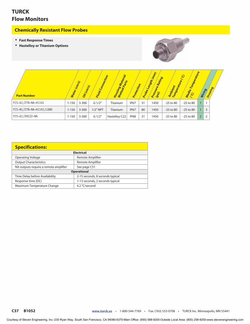
FCS-G1/2TN-NA-H1141 1-150 3-300 G 1/2" Titanium IP67 31 1450 -25 to 80 -25 to 80 1 1
FCS-N1/2TN-NA-H1141/L080 1-150 3-300 1/2" NPT Titanium IP67 80 1450 -25 to 80 -25 to 80 1 3
FCS-G1/2HC22-NA 1-150 3-300 G 1/2" Hastelloy C22 IP68 31 1450 -25 to 80 -25 to 80 2 2
• Fast Response Times
• Hastelloy or Titanium Options
Chemically Resistant Flow Probes
Specifications:Electrical
Operating Voltage Remote Amplifier
Output Characteristics Remote Amplifier
NA outputs require a remote amplifier See page C51
Operational
Time Delay before Availability 2-15 seconds, 8 seconds typical
Response time (DC) 1-13 seconds, 2 seconds typical
Maximum Temperature Change 4.2 °C/second
Courtesy of Steven Engineering, Inc.-230 Ryan Way, South San Francisco, CA 94080-6370-Main Office: (650) 588-9200-Outside Local Area: (800) 258-9200-www.stevenengineering.com

www.turck.us • 1-800-544-7769 • Fax: (763) 553-0708 • TURCK Inc. Minneapolis, MN 55441 B1052 C38
Flow Monitors
FL
OW
1
3
Wiring Diagrams
Drawings
Diagram 1
Mating Cordset:
RK 4.4T-*
Diagram 2
2M/PTFE Cable
2
L = Probe length
Courtesy of Steven Engineering, Inc.-230 Ryan Way, South San Francisco, CA 94080-6370-Main Office: (650) 588-9200-Outside Local Area: (800) 258-9200-www.stevenengineering.com

C39 B1052 www.turck.us • 1-800-544-7769 • Fax: (763) 553-0708 • TURCK Inc. Minneapolis, MN 55441
TURCK
Flow Monitors
Part Number Wa
ter
(cm
/s)
Oil
(cm
/s)
Flu
idC
on
ne
ctio
n
Ho
usi
ng
Ma
teri
al
We
tte
dP
art
s
Pro
tect
ion
Pro
be
Len
gth
Pre
ssu
reR
ati
ng
(psi
)
Am
bie
nt
Te
mp
era
ture
(C
)
Me
dia
Te
mp
era
ture
(C
)
Wir
ing
Dra
win
g
FCS-G1/4A4-NAEX 1-150 3-200 G 1/4" 316 TI SS IP68 25 1450 -25 to 80 -25 to 80 1 3
FCS-N1/2A4-NAEX-H1141 1-150 3-300 1/2" NPT 316 TI SS IP68 40 1450 -25 to 85 -25 to 85 2 1
FCS-N1/2A4-NAEX/D100 1-150 3-300 1/2" NPT 316 TI SS IP68 40 1450 -25 to 80 10 to 120 1 2
FCS-N1/2A4-NAEX 1-150 3-200 1/2" NPT 316 TI SS IP68 40 1450 -25 to 85 -25 to 85 1 2
FCS-GL1/2A4-NAEX/D500 1-150 3-300 GL1/2" 316 TI SS IP67 46 * -25 to 85 -25 to 85 1 4
* = 1000 dynamic, 5600 static
• Atex approved Flow Monitors
• Require an Amplifier
Intrinsically Safe Flow Probes
Specifications:Electrical
Operating Voltage Remote Amplifier
Output Characteristics Remote Amplifier
NA outputs require a remote amplifier See page C51
Intrinsically Safe Parameters
Approval Ex 112G, Eex Ib IIC T6
Maximum Power .69 W
Internal Inductance/Capacitance Negligible
Temperature Class T6: Tm ≤50 °C, T5: Tm ≤65 °C, T4: Tm ≤70 °C
Operational
Time Delay before Availability 2-15 seconds, 8 seconds typical
Response time 1-13 seconds, 2 seconds typical
Maximum Temperature Change 4.2 °C/second
Courtesy of Steven Engineering, Inc.-230 Ryan Way, South San Francisco, CA 94080-6370-Main Office: (650) 588-9200-Outside Local Area: (800) 258-9200-www.stevenengineering.com

www.turck.us • 1-800-544-7769 • Fax: (763) 553-0708 • TURCK Inc. Minneapolis, MN 55441 B1052 C40
Flow Monitors
FL
OW
Wiring Diagrams
Drawings
Diagram 1
Cable: 2m/PTFE
2m/PUR
Diagram 2
Mating cordset:
RK 4.41T-*
1 2
3 4
Courtesy of Steven Engineering, Inc.-230 Ryan Way, South San Francisco, CA 94080-6370-Main Office: (650) 588-9200-Outside Local Area: (800) 258-9200-www.stevenengineering.com