FCI Technology Investigations: L band Compatibility ... · PDF fileDocument title...
26
FCI Technology Investigations: L band Compatibility Criteria and Interference Scenarios Study Deliverable C5: Compatibility criteria and test specification for GNSS Edition Number 1.0 Edition Date 24/08/2009 Status Final COOPERATIVE NETWORK DESIGN
Transcript of FCI Technology Investigations: L band Compatibility ... · PDF fileDocument title...
FCI Technology Investigations: L band Compatibility Criteria and
Interference Scenarios Study
Deliverable C5: Compatibility criteria and test specification for GNSS
Edition Number 1.0 Edition Date 24/08/2009 Status Final
COOPERATIVE NETWORK DESIGN

P1031C4v5 HELIOS ii of 23
Document information
Document title Compatibility criteria and test specification for GNSS
Author Ian Casewell
Produced by Helios
29 Hercules Way
Aerospace Boulevard - AeroPark
Farnborough
Hampshire
GU14 6UU
UK
Produced for Eurocontrol
Helios contact John Micallef
Tel: +44 1252 451 651
Fax: +44 1252 451 652
Email: [email protected]
Produced under contract 08-111428-C
Version 1.0
Date of release 24/08/2009
Document reference P1031C5

P1031C4v5 HELIOS iii of 23
Contents
1 Introduction ............................................................................................................... 1
1.1 General ....................................................................................................................... 1
1.2 About this document.................................................................................................... 2
2 Characterisation of GNSS systems.......................................................................... 3
2.1 A brief description of GNSS systems........................................................................... 3
2.2 GNSS ranging signals ................................................................................................. 3
2.3 Mode of operation and characteristics of the avionics GNSS receivers ....................... 8
3 Compatibility criteria............................................................................................... 10
3.1 Introduction................................................................................................................ 10
3.2 GNSS receiver immunity requirements...................................................................... 10
3.3 Potential LDACS to GNSS interference scenarios ..................................................... 14
3.4 . Compatibility criteria ................................................................................................ 15
4 Test Plan .................................................................................................................. 20
4.1 Introduction................................................................................................................ 20
4.2 LDACS aircraft transmitter in-band and out of band EIRP tests ................................. 20
4.3 GNSS received power tests....................................................................................... 21
4.4 GNSS receiver performance degradation tests.......................................................... 22
5 References ............................................................................................................... 23
P1031C4v5 HELIOS 1 of 23
1 Introduction
1.1 General
1.1.1 Recognising that there is insufficient spectrum in the standard VHF band to support future aeronautical communications needs, two options for an L-Band Digital Aeronautical Communications System (L-DACS) have been identified by the European and US ICAO ACP members under the joint development activity known as the Future Communications Study (Action Plan 17). The first option for L-DACS is a frequency division duplex (FDD) configuration utilizing OFDM modulation techniques. The second LDACS option is a time division duplex (TDD) configuration utilising a binary (GMSK) modulation scheme.
1.1.2 One of the key questions with respect to these candidate L-DACS technologies which needs to be addressed is that of its compatibility with other, existing L-Band systems. Not only must the candidate systems be able to operate effectively whilst in the presence of interference from other systems, but they must also cause the minimum possible interference to the legacy systems. These compatibility analyses are required in order to assess the feasibility of using the competing L-DACS systems both in a ground, and in particular in an airborne environment.
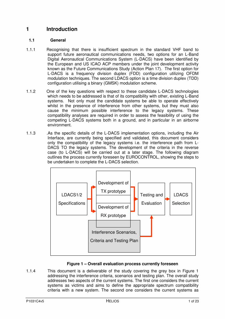
1.1.3 .As the specific details of the L-DACS implementation options, including the Air Interface, are currently being specified and validated, this document considers only the compatibility of the legacy systems i.e. the interference path from L-DACS TO the legacy systems. The development of the criteria in the reverse case (to L-DACS) will be carried out at a later stage. The following diagram outlines the process currently foreseen by EUROCONTROL, showing the steps to be undertaken to complete the L-DACS selection.
Figure 1 – Overall evaluation process currently foreseen
1.1.4 This document is a deliverable of the study covering the grey box in Figure 1 addressing the interference criteria, scenarios and testing plan. The overall study addresses two aspects of the current systems. The first one considers the current systems as victims and aims to define the appropriate spectrum compatibility criteria with a new system. The second one considers the current systems as
LDACS1/2
Specifications
Interference Scenarios,
Criteria and Testing Plan
Development of
TX prototype
Development of
RX prototype
Testing and
Evaluation
LDACS
Selection

P1031C4v5 HELIOS 2 of 23
interferers and aims to define the appropriate interference scenarios to be used when evaluating the impact of the current systems to a new system.
1.1.5 For the first part, there are 5 deliverables covering DME, UAT, SSR, GSM/UMTS and GNSS (C1, C2, C3, C4 and C5). For the second part, there is one deliverable consolidating the interference scenarios for all the previously considered systems and JTDS/MIDS in addition. There is also a combined deliverable (C6/S6) covering both the criteria and scenarios for the RSBN system. Finally there is one deliverable C7 providing an analysis of the potential usage of the suppression bus by a new system.
1.2 About this document
1.2.1 This document is deliverable C5 of the Spectrum Compatibility criteria and Interference Scenarios for existing systems operating in the L band study produced by Helios for Eurocontrol under Contract 08-111428-C as contribution to the Future Communication Study (FCS) activities, and in support of the work to realise one of the recommendations of the FCS to develop an L-band data link.
1.2.2 The development of the L-band data link is identified in the development activities for the SESAR Implementation Package 3 (IP3) in the post 2020 timeframe. Therefore, the outcome of this deliverable will be used as input to the SESAR JU development activities under WP15.2.4.
1.2.3 The criteria identified in this document are based on the current expected operating conditions of the proposed L-DACS systems, and on the published protection and susceptibility criteria for the technology alongside which L-DACS must operate. As such, issues such as frequency separation and emission masks for L-DACS are based on current expectations of the system parameters and final test validation will be necessary in order to confirm the implementation and test setup details herein documented. This paper is thus intended to provide the groundwork for the prototyping and compatibility trials bearing in mind that the compatibility criteria identified so far address interference in one direction where the legacy system is the victim.
1.2.4 The primary objective of this document is to develop compatibility criteria to ensure that GNSS receivers will continue to operate satisfactorily when operated in the proximity of the proposed LDACS system.
• Section 3 provides a high level description of the characteristic of current and future GNSS. In particular is provides tables describing the detailed signal characteristics.
• Section 3 derives the compatibility criteria by identifying the existing GNSS receiver immunity requirements, addressing the likely interference scenarios and estimating the resultant isolations.
• Section 4 concludes the report by proposing a test plan.
P1031C4v5 HELIOS 3 of 23
2 Characterisation of GNSS systems
2.1 A brief description of GNSS systems
2.1.1 Global Navigation Satellite System (GNSS) is a collective term for an increasing number of satellite navigation systems. Today the US GPS is well established after some 30 years of development and operational deployment. GPS, in both stand alone and augmented modes, is currently being used in a limited number of civil air navigation roles. The Russian counterpart to GPS known as GLONASS is less well established due to its reduced constellation. GLONASS FOC is not expected to be declared before 2010.
2.1.2 In the future, GPS and GLONASS are expected to be joined by the European GALILEO and the Chinese COMPASS systems.
2.1.3 All of the above systems share a common system architecture and similar signal structures. A generic GNSS consists of the following key elements:
• A constellation of 18 to 32 satellites in Medium Earth Orbit (MEO) which broadcast a number of ranging signals in L-band.
• A user community of receivers both civilian and military.
• A control segment consisting of a number of monitoring stations, a Master Control Station and a number of uplink stations operating in S or C band.
2.1.4 In addition to the basic system, both space based and ground based augmentation systems have been developed or are envisaged. These augmentation systems generally consist of a further set of monitor, or reference stations, a Master Control Station and a data link.
2.1.5 The FAA’s WAAS (Wide Area Augmentation System) system has been operational for several years and provides a small number of cloned GPS signals broadcast from geostationary satellites. Each of these signals provides an additional pseudo range and “correction” and integrity data within their navigation message. A European equivalent system known as EGNOS (European Geostationary Navigation Overlay Service) is expected to be certified for aviation use in the near future. Both of these systems support operations over a continental coverage area
2.1.6 The FAA is also developing a complementary ground based augmentation system known as LAAS (Local Area Augmentation System) for use in the immediate vicinity of an airport. An LAAS ground segment system consists of a number of reference stations and a VHF data link over which the DGPS corrections and integrity data are delivered to the aircraft.
2.2 GNSS ranging signals
2.2.1 Introduction
2.2.1.1 Each GNSS satellite transmits a ranging signal on a small number of L-band frequencies. Each ranging signal is modulated by a ranging code and, in most cases, a navigation message. The ranging codes are carefully selected pseudo random sequences with chip rates in the range 511 k Chips per second to 20.47 M Chips per second. A number of related modulation schemes are used. The inner
P1031C4v5 HELIOS 4 of 23
navigation signal data is synchronous with the chipping sequence and supports data rates in the range 50 to 500 bps.
2.2.1.2 Most GNSS employ a Code Division Multiple Access (CDMA) scheme except for the current GLONASS signals which use FDMA. GLONASS is expected to transition to CDMA over the coming years.
2.2.1.3 The following subsections will provide details of the ranging signals for the GPS, GLONASS and GALILEO systems.
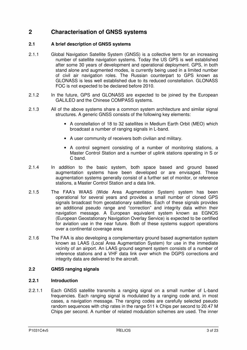
2.2.2 GPS
2.2.2.1 GPS currently broadcasts two ranging signals known as L1 and L2. These signals are planned to be augmented by an L5 signal. The L1 and L2 signals are being modified as part of the GPS modernisation program.
2.2.2.2 Details of the existing L1 and L2 GPS ranging signals are shown in Table 1.
Signal L1-C/A L1-P(Y) L2-P(Y)
Centre Freq. 1575.42 MHz 1227.60 MHz
Modulation QPSK BPSK
PRN chip rate 1.023 MCps 10.230 MCps 10.230 MCps
Navigation Message data rate 50 bps 50 bps 50 bps
(when enabled)
Occupied BW 2.0 MHz 20 MHz 20 MHz
Polarisation RHCP RHCP RHCP
Nominal received power at a 0dBi RHCP antenna
-159.6 dBW -162.6 dBW -165.2 dBW
Table 1, Characteristics of existing GPS ranging signals [1]
2.2.2.3 Details of the modernised GPS L1 ranging signals are shown in Table 2. An illustration of the spectrum of the L1 TMBOC civil signal is shown in Figure 2.
2.2.2.4 Details of the modernised GPS L2 ranging signals and the new GPS L5 ranging signals are shown in Table 3.

P1031C4v5 HELIOS 5 of 23
Signal L1-Cp [2] L1-Cd [2] L1-M [3] L1-P(Y) [4]
Centre Freq. 1575.42MHz
Modulation TMBOC
BOC(1,1) + BOC(6,1)
BOC(1,1) BOC(10,5) BPSK
Sub carrier Frequency 1.023 MHz
+ 6.138 MHz 1.023 MHz 10.23 MHz -
PRN chip rate 1.023 Mcps 1.023 Mcps 1.023 Mcps 10.23 MCps
Phase Relationship I-Phase (TBC) I-Phase I-Phase Q-Phase
Navigation Message data rate
N/A 50bps ? 50bps
Occupied BW approx 14 MHz 24MHz 20MHz
Polarisation RHCP RHCP RHCP RHCP
Nominal received power at a 0dBi RHCP antenna
-158.1 dBW -162.6 dBW Up to -140 dBW
over limited region
-162.6 dBW
Table 2, Characteristics of modernised L1 GPS ranging signals
Figure 2, BOC(1,1) and BOC(6,1) power spectrum (from [5])
P1031C4v5 HELIOS 6 of 23
Signal L2-C [4] L2-P(Y) [4] L2-M [3] L5 [6]
Centre Freq. 1227.60 MHz 1176.45 MHz
Modulation BPSK BPSK BOC(10,5) BPSK BPSK
Phase Relationship Q-Phase In-Phase Q-Phase In-Phase Q-Phase
PRN chip rate 0.5115 MCps
10.23 MCps 10.23 MCps 10.23 MCps
Navigation Message data rate
25 or 50 bps 50 bps ? 50 bps 0
Occupied BW 1.0 MHz 20 MHz 24 MHz 20 MHz 20 MHz
Polarisation RHCP RHCP RHCP RHCP RHCP
Nominal received power at a 0dBi RHCP antenna
-161.1 dBW -159.6 dBW Up to -140 dBW over
limited region -157.5 dBW -157.5 dBW
Table 3, Characteristics of modernised L2 and L5 GPS ranging signals
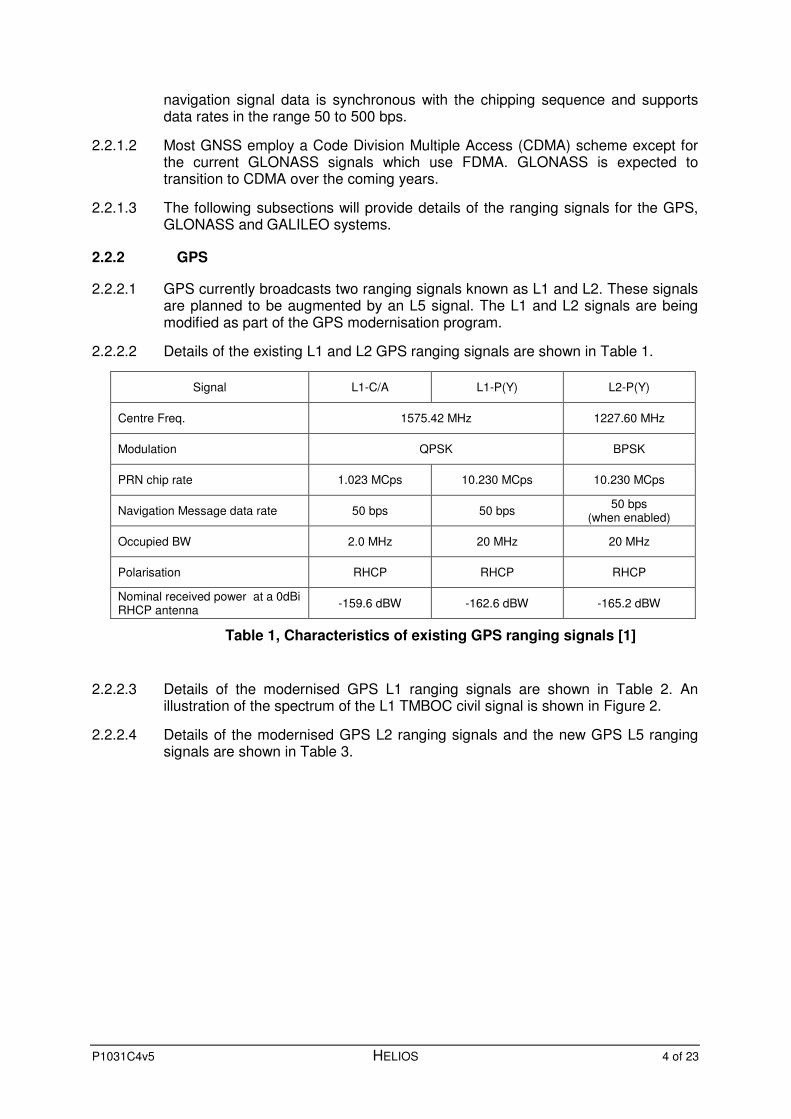
2.2.3 GLONASS
2.2.3.1 Details of the GLONASS ranging signals are shown in Table 3. It should be noted that unlike GPS and GALILEO GLONASS employs an FDMA access scheme.
2.2.3.2 It has recently been announced that future K generation satellites will employ a CDMS access scheme at L1 and L3 frequencies. The K generation of satellites are expected to be launched from 2010 onwards.
Signal L1-C/A L1-P L2-C L2-P L3
Centre Freq. 1595.0625 MHz to 1606.50
MHz in 0.5625 MHz channels
1242.93 MHz to 1249.25 MHz in 0.4375 MHz
channels
1196.3 MHz to 1204.9 MHz in
0.421MHz channels
Modulation QPSK QPSK QPSK
PRN chip rate 0.511 MCps 5.11 MCps 0.511 MCps 5.11 MCps 5.11 MCps
Navigation Message data rate 50bps 50bps 50bps 50 bps ?
Occupied BW 1.0 MHz 10 MHz 1.0 MHz 10MHz 10 MHz
Polarisation RHCP RHCP RHCP RHCP RHCP
Nominal received power at a 0dBi RHCP antenna
-155 dBW (estimated)
-155 dBW (estimated)
-155 dBW (estimated)
-155 dBW (estimated)
Not known
Table 3 Characteristics of GLONASS ranging signals [1] and [7].
P1031C4v5 HELIOS 7 of 23
2.2.4 GALILEO
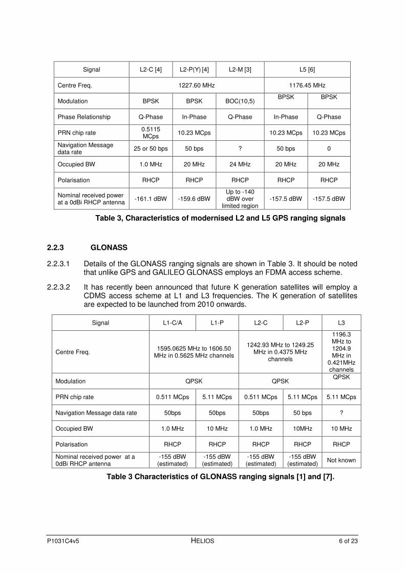
2.2.4.1 Details of the GALILEO E5 ranging signals are shown in Table 4.
2.2.4.2 Details of the GALILEO E6 ranging signals are shown in Table 5.
2.2.4.3 Details of the GALILEO E1 ranging signals are shown in Table 6.
Signal E5a data E5a pilot E5b data E5a pilot
Centre Freq. 1176.45 MHz 1207.14 MHz
Modulation Alt BOC(15,10) Alt BOC(15,10) Alt BOC(15,10) Alt BOC(15,10)
Sub-carrier 15.345 MHz 15.345 MHz 15.345 MHz 15.345 MHz
PRN chip rate 10.230 MCps 10.230 MCps 10.230 MCps 10.230 MCps
Phase Relationship I-Phase Q-Phase I-Phase Q-Phase
Navigation Message data rate
25bps 0 bps 125bps 0 bps
Occupied BW approx 20 MHz approx 20 MHz
Polarisation RHCP RHCP RHCP RHCP
Nominal received power at a 0dBi RHCP antenna
-158. dBW (min) -158. dBW (min) -158. dBW (min) --158. dBW (min)
Table 4 Characteristics of GAILIEO E5 signals [8].
Signal E6 CS data E6 CS pilot E6 PRS
Centre Freq. 1278.75 MHz
Modulation BPSK BPSK BOC(10,5)
Sub-carrier - - 10.23 MHz
PRN chip rate 5.115 MCps 5.115 MCps 5.115 MCps
Phase Relationship I-Phase Q-Phase -
Navigation Message data rate
500 bps 0 bps ?
Occupied BW approx 10 MHz approx 30 MHz
Polarisation RHCP RHCP RHCP
Nominal received power at a 0dBi RHCP antenna
-158. dBW (min) -158. dBW (min) -158. dBW (min)
Table 5 Characteristics of GAILIEO E6 signals [8].

P1031C4v5 HELIOS 8 of 23
Signal E1 OS data E1 OS pilot E1 PRS
Centre Freq. 1575.42 MHz
Modulation CBOC (6,1,1/11,+) CBOC (6,1,1/11,+) BOC(15,2.5)
Sub-carrier 1.023 Mcps
+ 6.138 Mcps- 1.023 Mcps
+ 6.138 Mcps - 15.435 MHz
PRN chip rate 1.023 MCps 1.023 MCps 2.5575 MCps
Phase Relationship I-Phase Q-Phase -
Navigation Message data rate
125bps 125 bps ?
Occupied BW approx 14 MHz approx 35 MHz
Polarisation RHCP RHCP RHCP
Nominal received power at a 0dBi RHCP antenna
-160. dBW (min) -160. dBW (min) ?
Table 6 Characteristics of GAILIEO E1 signals [8].
2.3 Mode of operation and characteristics of the avionics GNSS receivers
2.3.1 Navigation receivers are normally required to operate correctly continuously during the entire flight and are likely to be running at all times the aircraft’s avionics is powered up. However, due to the changing nature of the constellation, it is necessary to acquire new signals as the originating satellite rise above the pre-configure mask angle (normally 5° or 10°). The number of satellite visible depends upon the particular constellation and selected mask angle but can be expected to be in the range of 6 to 12 satellite per constellation. It may also be necessary to re-acquire a particular satellite’s signal following a signal shadowing event possible resulting from an aircraft manoeuvre.
2.3.2 It can be noted from the signal characteristics presented in Section 2.2 that the use of CDMA or FDMA access schemes implies that the signal transmission can be considered as continuous.
2.3.3 The minimum levels of the civil GNSS signals incident at a standard antenna (0dBi gain) are in the range -162 to -155 dBW. In practice, typical GPS antenna will have a peak gain of around 3 to 5 dB at zenith and so the gain at low elevation angle can fall to -2 or -4 dB. In practice receive powers in the range of around -164 to -150 dBW can be anticipated.
2.3.4 The aircraft’s GNSS antenna will be integrated with an adjactent Low Noise Amplifier and so a system noise temperature of the order of 300K is typical. Thus the likely carrier to noise density (C/No) can range from 38 to 52 dBHz. Modern C/A code GPS receivers are capable of acquiring signals with C/No’s of about 33 dBHz and tracking signals down to below 30 dBHz.
2.3.5 The use of an adjacent antenna and LNA means that the system noise temperature is not significantly affected by the long cable run needed to interconnect the antenna LNA assembly with the receiver installed in the cock pit or avionics bay.
P1031C4v5 HELIOS 9 of 23
2.3.6 Under optimal conditions, the satellite to air channel can be considered to be near Gaussian. However in some circumstances both defuse and specular multipath can cause the channel to become Rician. The correlation process fortunately provides welcome suppression of some of these multipath signals. The degree of multipath suppression is proportional to the chipping rate (or signal bandwidth) and so the modernised civil signals can be expected to inherently more tolerant of mutipath than the current generation of C/A code receivers. The presence of multipath can degrade code pseudo range noise significantly and so its suppression is of interest. This suppression can aided by careful design of the antenna, the careful selection of its location, the use of advanced correlator architectures and the use of carrier phase smoothing.
P1031C4v5 HELIOS 10 of 23
3 Compatibility criteria
3.1 Introduction
3.1.1 The objective of this section is to derive relevant compatibility criteria to ensure that the new LDACS system does not interfere with the existing GNSS receivers. In order to achieve this objective, the following steps must be performed:
• Identify the existing GNSS receiver immunity requirements for each of the GNSS signals used by the aviation community.
• Identify the potential LDACS to GNSS interference scenarios.
• Derive the key LDACS to GNSS compatibility criteria.
These three steps will be addressed in the following sub-sections.
3.2 GNSS receiver immunity requirements
3.2.1 The immunity requirements for the various GNSS receiver types currently permitted for aviation use are defined in the relevant Minimum Operational Performance Specifications (MOPS). These immunity requirements were derived from an assessment of the likely existing sources of interference that may interfere with the operation of the GNSS receiver. Whilst the MOPS for GPS L1 receiver is available [11]; published versions of the MOPS for GPS L5, GALILEO E5a/E5b and GLONASS are not yet available. In the absence of these MOPS, alternative documents must be sought. Fortunately, RTCA WG 159 has published a report entitled “Assessment of Radio Frequency Interference Relevant to the GNSS L5/E5A Frequency Band” [12]. Additionally a draft version of the MOPS for the GALILEO receiver [14] has been used in place of a published version.
3.2.2 Figure 3 shows the receiver immunity requirements for a GPS L1 receiver as stated in [11]. The related wording in [11] adds:
“The CW interference level below 1500 MHz increases linearly to 25.5 dBm at 1315 MHz. The CW level increases linearly above 1640 MHz, to 21.5 dBm at 2 GHz, accounting for High Intensity Radiation Fields (HIRF).”
The lower of the two curves in Figure 3 is valid for a CW interferer and the upper curve is valid for the case of a broadband (BB) interferer with a bandwidth between 100 kHz and 1,000 kHz. Should the bandwidth of the interfering signal differ, then adjustments must be made according to Figure 4. Furthermore a -6dB correction should be added to allow for reduced immunity during signal acquisition.
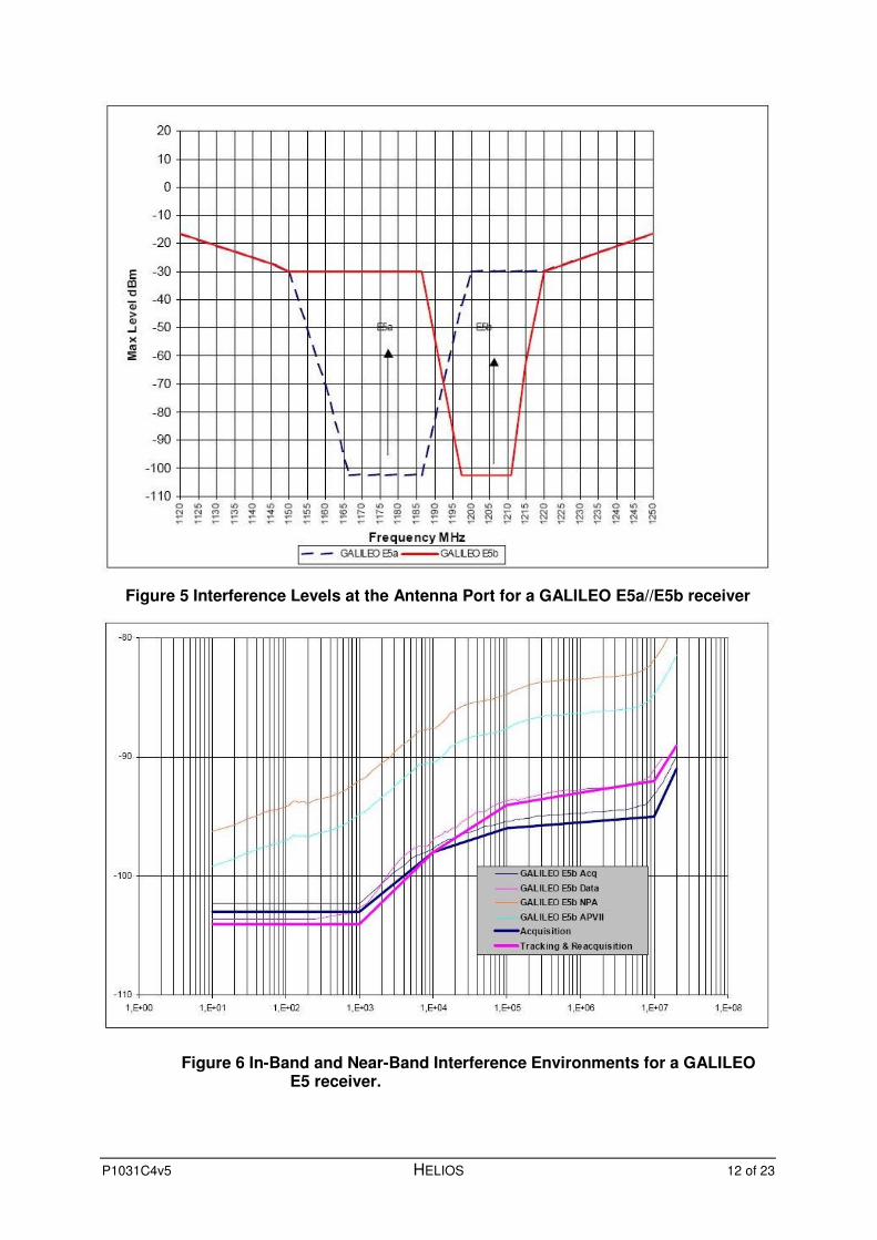
3.2.3 Figure 5 shows the receiver immunity requirements for a GALILEO E5a/E5b receiver as stated in Appendix B of [14]. Figure 5 shows the nin band and near band interference environment for the Galileo E5a/E5b receiver
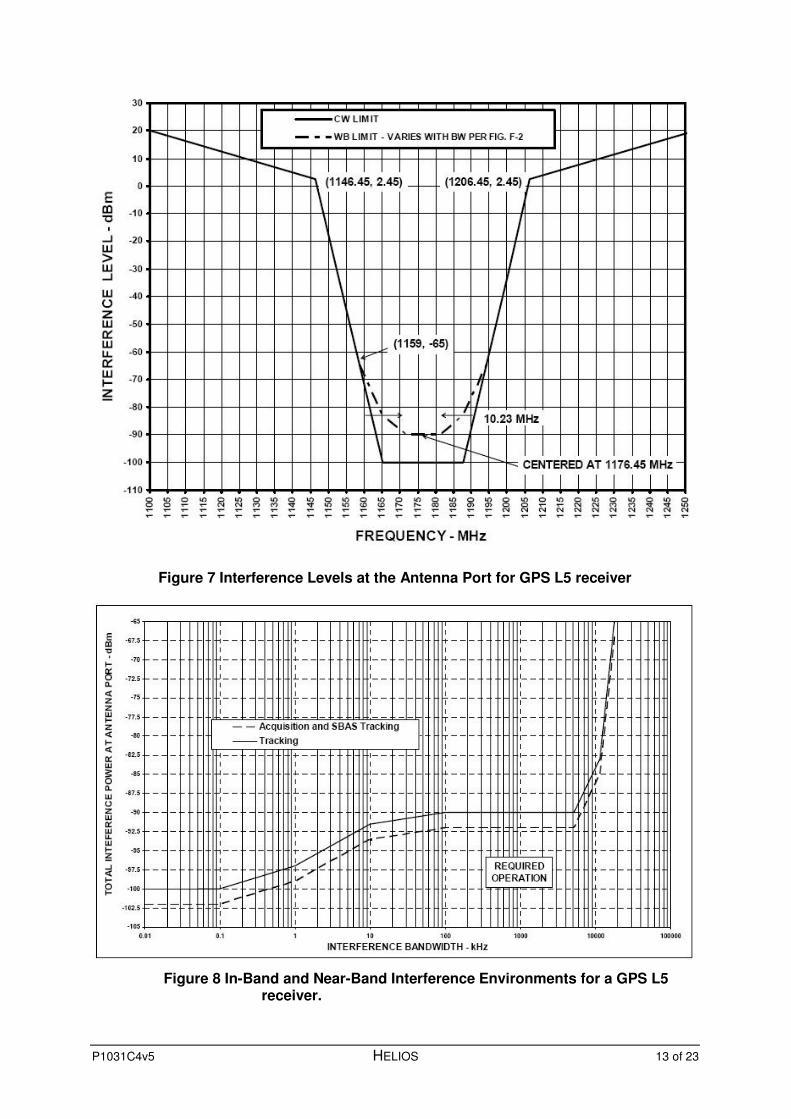
3.2.4 Figure 7 shows the receiver immunity requirements for a GPS L5 receiver as presented in [12].

P1031C4v5 HELIOS 11 of 23
-130
-120
-110
-100
-90
-80
-70
-60
-50
-40
-30
-20
-10
0
10
1500
1505
1510
1515
1520
1525
1530
1535
154
0
1545
1550
155
5
1560
156
5
157
0
1575
158
0
1585
1590
159
5
1600
1605
161
0
1615
1620
1625
1630
1635
1640
FREQUENCY - MHz
INT
ER
FE
RE
NC
E L
EV
EL
- d
Bm
40 MHz
CENTERED AT 1575.42 MHz
-89.5
(1525,-12)
(1626.5,+8)
-120.5
CW INTERFERENCE
BELOW LOWER LINE
INTERFERENCE
VARIES
WITH BANDWIDTH
BELOW -89.5 dBm
1 MHz
(1618,-12)
AIRCRAFT WITH SATCOM
ALL OTHERS
Figure 3 Interference Levels at the Antenna Port for GPS L1 receiver
-128 -126 -124 -122 -120 -118 -116 -114 -112 -110 -108 -106 -104 -102 -100
-98 -96 -94 -92 -90 -88
0.01 0.1 1 10 100 1000 10000 100000 INTERFERENCE BANDWIDTH - kHz
TERMINAL AREA, ENROUTE & ACQUISITION FOR ALL APPROACH (LNAV)
APPROACH (LNAV/VNAV, LP, LPV) OR SATCOM EQUIPPED
REQUIRED OPERATION
Figure 4 In-Band and Near-Band Interference Environments for a GPS L1 receiver.
P1031C4v5 HELIOS 12 of 23
Figure 5 Interference Levels at the Antenna Port for a GALILEO E5a//E5b receiver
Figure 6 In-Band and Near-Band Interference Environments for a GALILEO E5 receiver.
P1031C4v5 HELIOS 13 of 23
Figure 7 Interference Levels at the Antenna Port for GPS L5 receiver
Figure 8 In-Band and Near-Band Interference Environments for a GPS L5 receiver.

P1031C4v5 HELIOS 14 of 23
The lower of the two curves in Figure 7 is valid for a CW interferer and the upper curve is valid for the case of a broadband (BB) interferer with a bandwidth between 100 kHz and 15,000 kHz. Should the bandwidth of the interfering signal differ, then adjustments must be made according to Figure 8. Furthermore a -2dB correction should be added to allow for reduced immunity during signal acquisition.
As the referenced text makes no mention of the limits outside of the frequency range addressed in Figure 7, it will be assumed that the limit of 20 dBm applies over the range 950 to 1100 MHz and 1250 to 2000 MHz.
3.3 Potential LDACS to GNSS interference scenarios
3.3.1 The proposed LDACS system has the potential to cause interference the GNSS system in the following scenarios:
• Scenario 1; LDACS air to ground or air to air transmission into a GNSS receiver on the same aircraft.
• Scenario 2; LDACS air to ground or air to air transmission into GBAS reference station receiver.
• Scenario 3; LDACS air to ground or air to air transmission on one aircraft over flying a second aircraft containing the victim GNSS receiver.
3.3.2 For each of these scenarios it is necessary to estimate the minimum isolation, between the antenna of the LDACS transmitter and the victim GNSS receiver. To do this a number of assumptions must inevitably be made and thus any estimates made in this report should be confirmed by practical measurements.
3.3.3 For Scenario 1, the isolation between the LDACS transmitter and the victim receiver will very much depend upon the type of aircraft considered and the relative location of the two antennas. GNSS antennas are clearly mounted on the upper side of the fuselage; the LDACS antenna is expected to operate via either an antenna on the top of the fuselage or an antenna on the bottom of the fuselage. Clearly, the former is likely to be the worst case and if it is assumed that the two antennas are separated by at least 1.0m, then the free space loss is of the will be about 33 dB at 1100 MHz. The free space assumption is only valid for the far field case, but since both antennas are low gain, the free space assumption is likely to be valid. Section 5.1 of reference [9] addresses this issue and states:
“Isolation between co-sited antennas placed on the same side of the aircraft (both at the top or both at the bottom) will be computed as of 35 dB whereas the isolation between antennas placed on opposite sides of the aircraft (one of them at the top and the other at the bottom) will be computed as of 45 dB.”
This is considered to be consistent with the above estimate of 33 dB.
3.3.4 For scenario 2; the victim is a GBAS ground reference receiver whose antenna may, in a worst case, be installed in close proximity to an active run way. From pure safety considerations fixed infrastructure should be located at a reasonable distance from an active run way centre line. FAA documents suggest that the minimum width of the lateral runway clearance zone should be at least 2000ft

P1031C4v5 HELIOS 15 of 23
[10]. Thus it is reasonable to assume that the minimum distance between the two antennas will be 300m. The resulting minimum free space path loss is 83dB at 1100MHz.
3.3.5 For scenario 3; the worst case path loss is determined by the minimum vertical air craft separation criteria for a given phase of flight. For aircraft flying below FL290 the minimum vertical separation criteria is 1000ft (300m). The resulting minimum free space path loss is 83dB at 1100MHz.
3.3.6 In interference analyses it is normal to include a safety factor of 10 dB.
3.3.7 It is concluded that Scenario 1 is the most significant and so the following compatibility criteria will be derived using a minimum isolation of 23 dB.
3.4 . Compatibility criteria
3.4.1 In order to derive the compatibility criteria it is necessary to re-formulate the above GNSS immunity requirements in to the context of the LDACS system. This is achieved by including the intersystem isolation and the antenna gain of the GNSS antenna in the direction of the LDACS antenna. Hence:
fAntfGNSSfLDACS IGPEIRP +−= dBW
Where: fLDACSEIRP is the maximum EIRP allowable from the LDACS
transmitter in the direction of the victim GNSS receiver at a frequency of f.
fGNSSP is the maximum permitted interfering power at the input of the
GNSS receiver and at frequency f obtained from section 3.2.
AntG is the gain of the GNSS antenna in the direction of the LDACS
transmitting antenna. For the purposes of this work it will be assumed that this gain is 0dB. Could consider reducing to -2dB, see DO292 App G.
fI is the intersystem isolation at frequency f.
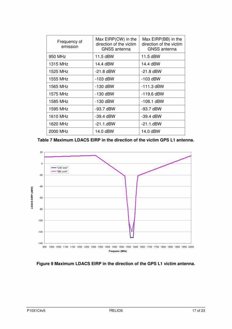
3.4.2 Compatibility Criterion No 1
3.4.2.1 This Compatibility Criterion is intended to ensure the satisfactory coexistence of a GPS L1 receiver and an LDACS airborne transmitter co-sited on the same aircraft (Scenario 1).
3.4.2.2 The estimated limits for a CW and Broadband interferer calculated using the equation and assumptions above are shown in Table 7 and Figure 9.
3.4.3 Compatibility Criterion No 2
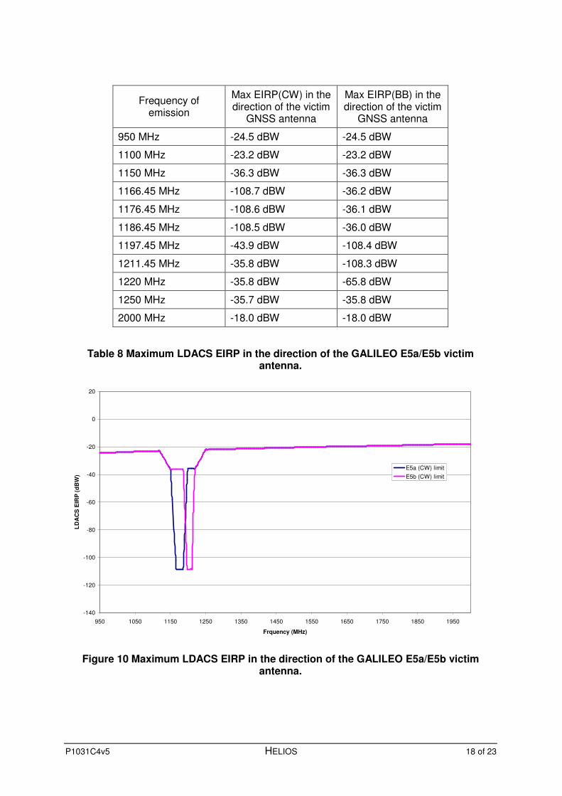
3.4.3.1 This Compatibility Criterion is intended to ensure the satisfactory coexistence of a GALILEO E5a/E5b receiver and an LDACS airborne transmitter co-sited on the same aircraft (Scenario 1).
3.4.3.2 The estimated limits for a CW interferer calculated using the equation and assumptions above are shown in Table 8 and Figure 10.
P1031C4v5 HELIOS 16 of 23
3.4.4 Compatibility Criterion No 3
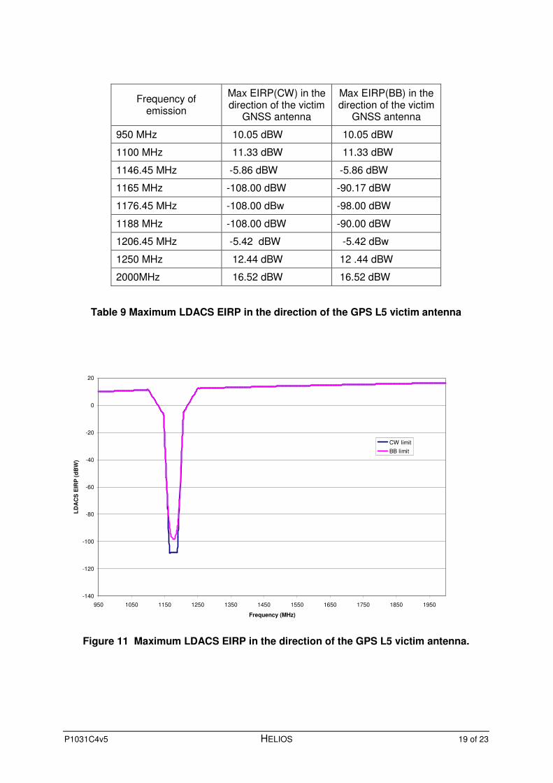
3.4.4.1 This Compatibility Criterion is intended to ensure the satisfactory coexistence of a GPS L5 receiver and an LDACS airborne transmitter co-sited on the same aircraft (Scenario 1).
3.4.4.2 The estimated limits for a CW and Broadband interferer calculated using the equation and assumptions above are shown in Table 9 and Figure 11.
P1031C4v5 HELIOS 17 of 23
Frequency of emission
Max EIRP(CW) in the direction of the victim
GNSS antenna
Max EIRP(BB) in the direction of the victim
GNSS antenna
950 MHz 11.5 dBW 11.5 dBW
1315 MHz 14.4 dBW 14.4 dBW
1525 MHz -21.8 dBW -21.8 dBW
1555 MHz -103 dBW -103 dBW
1565 MHz -130 dBW -111.3 dBW
1575 MHz -130 dBW -119.6 dBW
1585 MHz -130 dBW -108.1 dBW
1595 MHz -93.7 dBW -93.7 dBW
1610 MHz -39.4 dBW -39.4 dBW
1620 MHz -21.1.dBW -21.1.dBW
2000 MHz 14.0 dBW 14.0 dBW
Table 7 Maximum LDACS EIRP in the direction of the victim GPS L1 antenna.
-140
-120
-100
-80
-60
-40
-20
0
20
950 1000 1050 1100 1150 1200 1250 1300 1350 1400 1450 1500 1550 1600 1650 1700 1750 1800 1850 1900 1950 2000
Frequenc (MHz)
LD
AC
S E
IRP
(d
BW
)
"CW limit"
"BB Limit"
Figure 9 Maximum LDACS EIRP in the direction of the GPS L1 victim antenna.
P1031C4v5 HELIOS 18 of 23
Frequency of emission
Max EIRP(CW) in the direction of the victim
GNSS antenna
Max EIRP(BB) in the direction of the victim
GNSS antenna
950 MHz -24.5 dBW -24.5 dBW
1100 MHz -23.2 dBW -23.2 dBW
1150 MHz -36.3 dBW -36.3 dBW
1166.45 MHz -108.7 dBW -36.2 dBW
1176.45 MHz -108.6 dBW -36.1 dBW
1186.45 MHz -108.5 dBW -36.0 dBW
1197.45 MHz -43.9 dBW -108.4 dBW
1211.45 MHz -35.8 dBW -108.3 dBW
1220 MHz -35.8 dBW -65.8 dBW
1250 MHz -35.7 dBW -35.8 dBW
2000 MHz -18.0 dBW -18.0 dBW
Table 8 Maximum LDACS EIRP in the direction of the GALILEO E5a/E5b victim antenna.
-140
-120
-100
-80
-60
-40
-20
0
20
950 1050 1150 1250 1350 1450 1550 1650 1750 1850 1950
Frquency (MHz)
LD
AC
S E
IRP
(d
BW
)
E5a (CW) limit
E5b (CW) limit
Figure 10 Maximum LDACS EIRP in the direction of the GALILEO E5a/E5b victim antenna.
P1031C4v5 HELIOS 19 of 23
Frequency of emission
Max EIRP(CW) in the direction of the victim
GNSS antenna
Max EIRP(BB) in the direction of the victim
GNSS antenna
950 MHz 10.05 dBW 10.05 dBW
1100 MHz 11.33 dBW 11.33 dBW
1146.45 MHz -5.86 dBW -5.86 dBW
1165 MHz -108.00 dBW -90.17 dBW
1176.45 MHz -108.00 dBw -98.00 dBW
1188 MHz -108.00 dBW -90.00 dBW
1206.45 MHz -5.42 dBW -5.42 dBw
1250 MHz 12.44 dBW 12 .44 dBW
2000MHz 16.52 dBW 16.52 dBW
Table 9 Maximum LDACS EIRP in the direction of the GPS L5 victim antenna
-140
-120
-100
-80
-60
-40
-20
0
20
950 1050 1150 1250 1350 1450 1550 1650 1750 1850 1950
Frequency (MHz)
LD
AC
S E
IRP
(d
BW
)
CW limit
BB limit
Figure 11 Maximum LDACS EIRP in the direction of the GPS L5 victim antenna.

P1031C4v5 HELIOS 20 of 23
4 Test Plan
4.1 Introduction
4.1.1 The primary test involves the measurement of the in-band and out of band EIRP of the LDACS aircraft transmitter in the direction of the victim GNSS receiver antenna. This test is defined in section 4.2.
4.1.2 A secondary test involves the measurement of the received power at a typical GNSS victim antenna from a LDACS aircraft transmitter when the LDACS and GNSS antenna are mounted on a test rig intended to simulate the worst case physical configuration likely to be encountered in practice. This test is defined in section 4.3.
4.1.3 An alternative secondary test involves the measurement of the C/No degradation and acquisition performance of sample of avionics GNSS receivers in the presence an LDACS aircraft transmitter. Again the LDACS and GNSS antennas are mounted on a test rig intended to simulate the worst case physical configuration likely to be encountered in practice. This test is defined in section 4.4. To perform the acquisition tests with any confidence, it is necessary to employ a large anechoic chamber and GNSS signal simulation equipment. It is acknowledged that such a test may be prohibitively expensive.
4.2 LDACS aircraft transmitter in-band and out of band EIRP tests
4.2.1 In this test, the in-band and out of band EIRP of the LDACS aircraft transmitter is measured in two steps. These tests must be performed with the LDACS transmitter transmitting at maximum power
4.2.2 The first step involves the measurement of the LDACS transmitter power at the point at which it would normally connect to the LDACS antenna. This implies that the effects of the shortest anticipated transmitter to antenna cable run are included. This is performed using the test setup shown in Figure 12. The notch filter should be tuned to the LDACS transmit frequency and provide sufficient rejection to protect the spectrum analyser from damage when the input attenuator is reduced to 0 dB. The directional coupler should have a nominal coupling factor of 20 dB.
Figure 12 LDACS transmitter power measurement setup
LDACS Tx
under testNotch Filter
High Power
Load
Spectrum
Analyser
A
B
Feeder Cable
C
P1031C4v5 HELIOS 21 of 23
4.2.3 The test setup must first be calibrated using a network analyser to measure the insertion loss between points A to B and A to C over the frequency band of 950 to 2000MHz. The unused port B or C should be terminated with a 50Ω load.
4.2.4 The in band transmit power is measured at point C using the spectrum analyser with the resolution bandwidth set to accommodate the bandwidth of the wanted signal. Terminate point B with a 50Ω load. The LDACS transmitter power is then calculated by correcting for the calibrated loss from point A to C.
4.2.5 The CW out of band transmit power1 in the frequency range 0.950 to 2 GHz is measured at point B using the spectrum analyser. The spectrum analyser resolution BW should be set to 10 KHz and the input attenuation should be set to 0 dB. Terminate point C with a 50Ω load. The LDACS transmitter power is then calculated by correcting for the loss from point A to B measured in paragraph 4.2.3.
4.2.6 The broadband out of band transmit powers are measured as in paragraph 4.2.5 except that the spectrum analyser’s resolution bandwidth should be set to 1MHz.
4.2.7 The second step requires the measurement of the LDACS antenna gain in an anechoic chamber or an open field test range. For these tests the antenna should be mounted on a conductive structure to simulate the typical aircraft fuselage. Note; test results may be obtainable from the antenna manufacturer.
4.2.8 Finally, the In band and out of band EIRP is computed by summing (in dB) the measured transmit power and the measured antenna gain in the direction of the victim GNSS receiver antenna.
4.2.9 The upper limits of the LDACS EIRP are as defined in section 3.4 above.
4.3 GNSS received power tests
4.3.1 In this test the power incident at the output of a typical GNSS antenna is measured whilst an LDACS transmitter is radiating at full power. Both the LDACS and GNSS antennas should be mounted on a conductive structure to simulate the typical aircraft fuselage. The antennas should be spaced 1 m apart on the top centre line of the structure. Clearly, the GNSS antenna type should be appropriate for the specific GNSS signal e.g. GPS L5.
4.3.2 The tests shall be performed with a range of GNSS antennas such that all signal types are addressed.
4.3.3 With the LDACS transmitter transmitting at maximum power, use a spectrum analyser to measure the CW power2 in the frequency range 0.950 to 2 GHz. The Spectrum Analyser’s resolution bandwidth should be set to 1.0 KHz and the input attenuator set to 0dB.
4.3.4 With the LDACS transmitter transmitting at maximum power, use a spectrum analyser to measure the broadband noise power in the frequency range 0.950 to 2 GHz. The Spectrum Analyser’s resolution bandwidth should be set to 1.0MHz and the input attenuator set to 0dB. Note; it may be necessary to insert
1 the LDAS transmitter is operating in a pulsed mode, measure the peak power.
2 If the LDAS transmitter is operating in a pulsed mode, measure the peak power.
P1031C4v5 HELIOS 22 of 23
a calibrated low noise amplifier between the antenna and Spectrum analyser in order to provide sufficient sensitivity.
4.3.5 The upper limits for the GNSS receiver input powers defined in section 3.2 above.
4.4 GNSS receiver performance degradation tests
4.4.1 In this test, a complete simulated LDACS aircraft transmitter and typical avionics GNSS receiver installation is tested on a real aircraft of an appropriate type or a on a conductive structure to simulate the typical aircraft fuselage. The antennas should be spaced 1 m apart on the top centre line of the structure.
4.4.2 The tests shall be performed with a range of GNSS antennas and receivers such that all signal types are addressed.
4.4.3 With the LDACS aircraft transmitter off, set up the GNSS receiver to operate normally. Once the anticipated number of GNSS signals has been acquired, for each signal log the C/No reported by the receiver at a sample rate of once per 10 sec for a period of 1 minute. Switch on the LDACS transmitter and ensure that it is operating at full power. Again, log the C/No reported by the receiver at a sample rate of once per 10 sec for a period of 1 minute. Finally compare the two sets of C/No measurements. The level of acceptable degradation on each signal shall be carefully determined for each signal type. Hegarty, in [13] suggests that the allowable degradation for L5 could be set at 5.8 dB.3
4.4.4 In order to fully test for any degradation in the GNSS receivers acquisition performance, it is necessary to perform the tests in a large anechoic chamber with a single simulated radiated GNSS signal of the appropriate type and power level set to the receivers specified acquisition threshold. With the LDACS aircraft transmitter off, measure the time taken to acquire this signal at least 100 times and plot the cumulative probability of acquisition versus time. Repeat the acquisition test with the LDACS aircraft transmitter on and plot the cumulative probability of acquisition versus time on the same graph. The level of acceptable degradation in acquisition performance shall, again be carefully determined.
3 If the test in paragraph 4.4.4 is performed in an anechoic chamber, then this test may be also
performed with simulated GNSS signals. The constellation and signal power levels should set to provide the range of C/No expected in normal use.

P1031C4v5 HELIOS 23 of 23
5 References
[1] E Kaplan (editor) Understanding GPS, principles and applications. Artech House.
[2] Dept of the Air Force (US) Interface Specification (IS-GPS-800), Navstar GPS space segment/User segment L1C interfaces. Draft version dated 31st March 2008.
[3] Capt. Brian C. Barker, Overview of the GPS M Code Signal.
[4] Dept of the Air Force (US) Interface Specification (IS-GPS-200D), Navstar GPS Space Segment/Navigation User Interfaces. 7th December 2004.
[5] N Hoult et al MBOC and BOC(1,1) performance comparison. The Journal of Navigation. Vol 61, No 4, October 2008. Cambridge University Press.
[6] Dept of the Air Force (US) Interface Specification (IS-GPS-700), Navstar GPS Space Segment / User Segment L5 Interfaces. Version issued on 22nd September 2005.
[7] Federal Space Agency of the Russian Federation. GLONASS status and perspectives. Slides presented at Civil GPS service interface committee meeting, Prague, 14th to 15th March 2005.
[8] J A Avia-Rodriguez et al The MBOC Modulation: the final touch to the GALILEO frequency and signal plan. Navigation, Journal of the Institute of Navigation, Spring 2008 Vol 55 No1.
[9] AENA/DSNA Framework for Spectrum Compatibility Analysis in L-Band for FCI technology Candidates. Draft 1.0.
[10] FAA Order JO 7400.2G of April 10, 2008, Subject: Procedures for Handling Airspace Matters, Section 3. Identifying/Evaluating Aeronautical Effect.
[11] RTCA Appendix C of DO229D. Minimum Operational Performance Standards for Global Positioning System/Wide Area Augmentation System Airborne Equipment. Dec 200
[12] RTCA DO-292 Assessment of Radio Frequency Interference Relevant to the GNSS L5/E5A Frequency Band,” 29th July 2004.
[13] Hegarty et al Methodology for determining compatibility of GPS L5 with existing systems and preliminary results.
[14] EUROCAE Interim Minimum Operational Performance Specification for airborne GALILEO satellite receiving equipment. Version 0.25, October 2007.
![Pre-Test L-1-Version B2 [Compatibility Mode]](https://static.fdocuments.us/doc/165x107/577cdf551a28ab9e78b0fbc2/pre-test-l-1-version-b2-compatibility-mode.jpg)
![Pre-Test L-1-Version B1 [Compatibility Mode]](https://static.fdocuments.us/doc/165x107/55cfe3fe5503467d968b7263/pre-test-l-1-version-b1-compatibility-mode.jpg)


![Drugi Test - Tema 1. Ekoloske Fasade [Compatibility Mode]](https://static.fdocuments.us/doc/165x107/55cf9801550346d03394f6fb/drugi-test-tema-1-ekoloske-fasade-compatibility-mode.jpg)