FCC Statement INSTALL SAFETY Installing the Enphase IQ Envoy
2
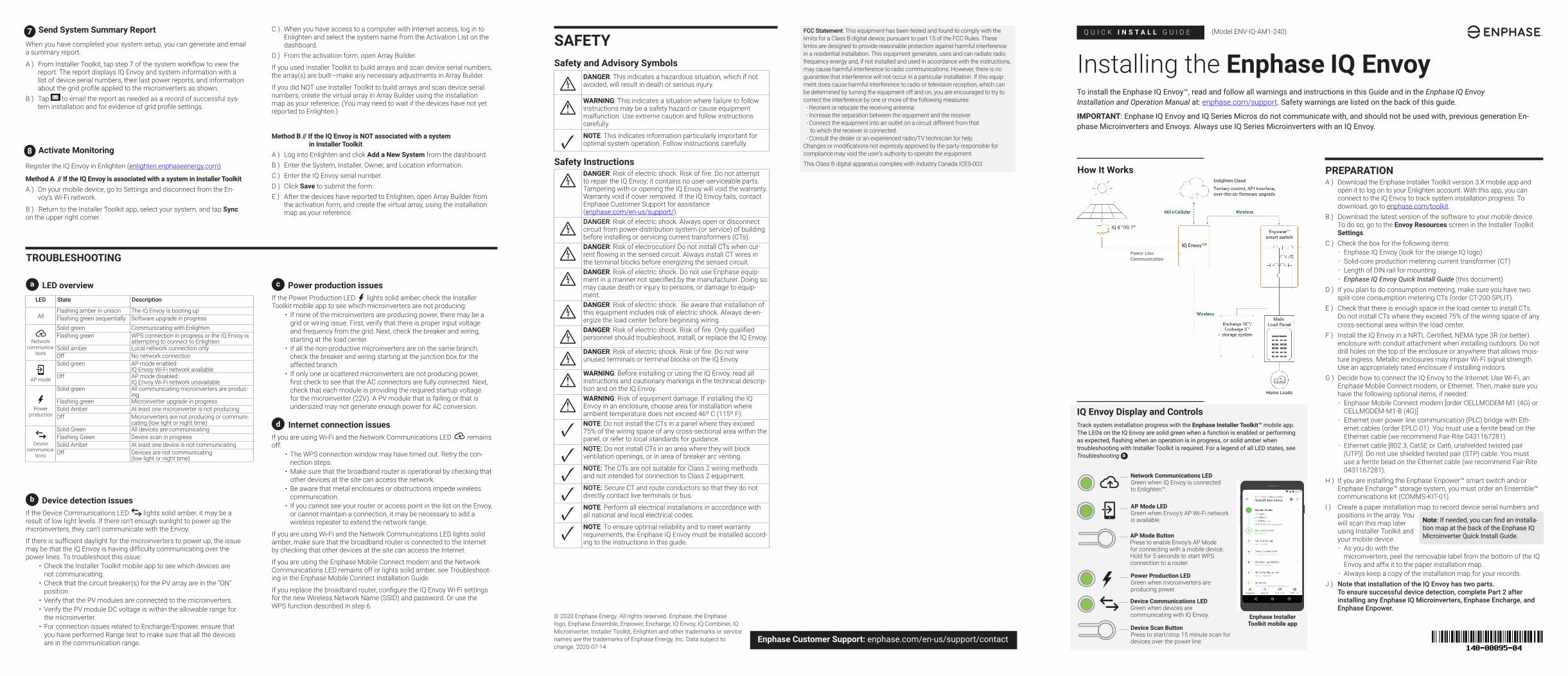
QUICK INSTALL GUIDE Installing the Enphase IQ Envoy To install the Enphase IQ Envoy™, read and follow all warnings and instructions in this Guide and in the Enphase IQ Envoy Installation and Operation Manual at: enphase.com/support. Safety warnings are listed on the back of this guide. IMPORTANT: Enphase IQ Envoy and IQ Series Micros do not communicate with, and should not be used with, previous generation En- phase Microinverters and Envoys. Always use IQ Series Microinverters with an IQ Envoy. PREPARATION A ) Download the Enphase Installer Toolkit version 3.X mobile app and open it to log on to your Enlighten account. With this app, you can connect to the IQ Envoy to track system installation progress. To download, go to enphase.com/toolkit. B ) Download the latest version of the software to your mobile device. To do so, go to the Envoy Resources screen in the Installer Toolkit Settings. C ) Check the box for the following items: • Enphase IQ Envoy (look for the orange IQ logo) • Solid-core production metering current transformer (CT) • Length of DIN rail for mounting • Enphase IQ Envoy Quick Install Guide (this document) D ) If you plan to do consumption metering, make sure you have two split-core consumption metering CTs (order CT-200-SPLIT). E ) Check that there is enough space in the load center to install CTs. Do not install CTs where they exceed 75% of the wiring space of any cross-sectional area within the load center. F ) Install the IQ Envoy in a NRTL Certified, NEMA type 3R (or better) enclosure with conduit attachment when installing outdoors. Do not drill holes on the top of the enclosure or anywhere that allows mois- ture ingress. Metallic enclosures may impair Wi-Fi signal strength. Use an appropriately rated enclosure if installing indoors. G ) Decide how to connect the IQ Envoy to the Internet: Use Wi-Fi, an Enphase Mobile Connect modem, or Ethernet. Then, make sure you have the following optional items, if needed: • Enphase Mobile Connect modem [order CELLMODEM-M1 (4G) or CELLMODEM-M1-B (4G)] • Ethernet over power line communication (PLC) bridge with Eth- ernet cables (order EPLC-01). You must use a ferrite bead on the Ethernet cable (we recommend Fair-Rite 0431167281). • Ethernet cable [802.3, Cat5E or Cat6, unshielded twisted pair (UTP)]. Do not use shielded twisted pair (STP) cable. You must use a ferrite bead on the Ethernet cable (we recommend Fair-Rite 0431167281). H ) If you are installing the Enphase Enpower™ smart switch and/or Enphase Encharge™ storage system, you must order an Ensemble™ communications kit (COMMS-KIT-01). I ) Create a paper installation map to record device serial numbers and positions in the array. You will scan this map later using Installer Toolkit and your mobile device. • As you do with the microinverters, peel the removable label from the bottom of the IQ Envoy and affix it to the paper installation map. • Always keep a copy of the installation map for your records. J ) Note that installation of the IQ Envoy has two parts. To ensure successful device detection, complete Part 2 after installing any Enphase IQ Microinverters, Enphase Encharge, and Enphase Enpower. Note: If needed, you can find an installa- tion map at the back of the Enphase IQ Microinverter Quick Install Guide. (Model ENV-IQ-AM1-240) IQ Envoy Display and Controls Network Communications LED Green when IQ Envoy is connected to Enlighten™. AP Mode LED Green when Envoy’s AP Wi-Fi network is available. AP Mode Button Press to enable Envoy’s AP Mode for connecting with a mobile device. Hold for 5 seconds to start WPS connection to a router. Power Production LED Green when microinverters are producing power. Device Communications LED Green when devices are communicating with IQ Envoy. Device Scan Button Press to start/stop 15 minute scan for devices over the power line. Track system installation progress with the Enphase Installer Toolkit™ mobile app. The LEDs on the IQ Envoy are solid green when a function is enabled or performing as expected, flashing when an operation is in progress, or solid amber when troubleshooting with Installer Toolkit is required. For a legend of all LED states, see Troubleshooting a . Enphase Installer Toolkit mobile app How It Works Enphase Customer Support: enphase.com/en-us/support/contact FCC Statement: This equipment has been tested and found to comply with the limits for a Class B digital device, pursuant to part 15 of the FCC Rules. These limits are designed to provide reasonable protection against harmful interference in a residential installation. This equipment generates, uses and can radiate radio frequency energy and, if not installed and used in accordance with the instructions, may cause harmful interference to radio communications. However, there is no guarantee that interference will not occur in a particular installation. If this equip- ment does cause harmful interference to radio or television reception, which can be determined by turning the equipment off and on, you are encouraged to try to correct the interference by one or more of the following measures: - Reorient or relocate the receiving antenna. - Increase the separation between the equipment and the receiver. - Connect the equipment into an outlet on a circuit different from that to which the receiver is connected. - Consult the dealer or an experienced radio/TV technician for help. Changes or modifications not expressly approved by the party responsible for compliance may void the user’s authority to operate the equipment. This Class B digital apparatus complies with Industry Canada ICES-003. SAFETY Safety and Advisory Symbols + DANGER: This indicates a hazardous situation, which if not avoided, will result in death or serious injury. * WARNING: This indicates a situation where failure to follow instructions may be a safety hazard or cause equipment malfunction. Use extreme caution and follow instructions carefully. ✓ NOTE: This indicates information particularly important for optimal system operation. Follow instructions carefully. Safety Instructions + DANGER: Risk of electric shock. Risk of fire. Do not attempt to repair the IQ Envoy; it contains no user-serviceable parts. Tampering with or opening the IQ Envoy will void the warranty. Warranty void if cover removed. If the IQ Envoy fails, contact Enphase Customer Support for assistance (enphase.com/en-us/support/). + DANGER: Risk of electric shock. Always open or disconnect circuit from power-distribution system (or service) of building before installing or servicing current transformers (CTs). + DANGER: Risk of electrocution! Do not install CTs when cur- rent flowing in the sensed circuit. Always install CT wires in the terminal blocks before energizing the sensed circuit. + DANGER: Risk of electric shock. Do not use Enphase equip- ment in a manner not specified by the manufacturer. Doing so may cause death or injury to persons, or damage to equip- ment. + DANGER: Risk of electric shock. Be aware that installation of this equipment includes risk of electric shock. Always de-en- ergize the load center before beginning wiring. + DANGER: Risk of electric shock. Risk of fire. Only qualified personnel should troubleshoot, install, or replace the IQ Envoy. + DANGER: Risk of electric shock. Risk of fire. Do not wire unused terminals or terminal blocks on the IQ Envoy. * WARNING: Before installing or using the IQ Envoy, read all instructions and cautionary markings in the technical descrip- tion and on the IQ Envoy. * WARNING: Risk of equipment damage. If installing the IQ Envoy in an enclosure, choose area for installation where ambient temperature does not exceed 46º C (115º F). ✓ NOTE: Do not install the CTs in a panel where they exceed 75% of the wiring space of any cross-sectional area within the panel, or refer to local standards for guidance. ✓ NOTE: Do not install CTs in an area where they will block ventilation openings, or in area of breaker arc venting. ✓ NOTE: The CTs are not suitable for Class 2 wiring methods and not intended for connection to Class 2 equipment. ✓ NOTE: Secure CT and route conductors so that they do not directly contact live terminals or bus. ✓ NOTE: Perform all electrical installations in accordance with all national and local electrical codes. ✓ NOTE: To ensure optimal reliability and to meet warranty requirements, the Enphase IQ Envoy must be installed accord- ing to the instructions in this guide. Register the IQ Envoy in Enlighten (enlighten.enphaseenergy.com). Method A // If the IQ Envoy is associated with a system in Installer Toolkit A ) On your mobile device, go to Settings and disconnect from the En- voy’s Wi-Fi network. B ) Return to the Installer Toolkit app, select your system, and tap Sync on the upper right corner. Activate Monitoring a LED overview LED State Description All Flashing amber in unison The IQ Envoy is booting up Flashing green sequentially Software upgrade in progress Network communica- tions Solid green Communicating with Enlighten Flashing green WPS connection in progress or the IQ Envoy is attempting to connect to Enlighten Solid amber Local network connection only Off No network connection AP mode Solid green AP mode enabled: IQ Envoy Wi-Fi network available Off AP mode disabled: IQ Envoy Wi-Fi network unavailable Power production Solid green All communicating microinverters are produc- ing Flashing green Microinverter upgrade in progress Solid Amber At least one microinverter is not producing Off Microinverters are not producing or communi- cating (low light or night time) Device communica- tions Solid Green All devices are communicating Flashing Green Device scan in progress Solid Amber At least one device is not communicating Off Devices are not communicating (low light or night time) TROUBLESHOOTING b Device detection issues If the Device Communications LED lights solid amber, it may be a result of low light levels. If there isn’t enough sunlight to power up the microinverters, they can’t communicate with the Envoy. If there is sufficient daylight for the microinverters to power up, the issue may be that the IQ Envoy is having difficulty communicating over the power lines. To troubleshoot this issue: • Check the Installer Toolkit mobile app to see which devices are not communicating. • Check that the circuit breaker(s) for the PV array are in the “ON” position. • Verify that the PV modules are connected to the microinverters. • Verify the PV module DC voltage is within the allowable range for the microinverter. • For connection issues related to Encharge/Enpower, ensure that you have performed Range test to make sure that all the devices are in the communication range. Send System Summary Report When you have completed your system setup, you can generate and email a summary report. A ) From Installer Toolkit, tap step 7 of the system workflow to view the report. The report displays IQ Envoy and system information with a list of device serial numbers, their last power reports, and information about the grid profile applied to the microinverters as shown. B ) Tap to email the report as needed as a record of successful sys- tem installation and for evidence of grid profile settings. 7 8 C ) When you have access to a computer with Internet access, log in to Enlighten and select the system name from the Activation List on the dashboard. D ) From the activation form, open Array Builder. If you used Installer Toolkit to build arrays and scan device serial numbers, the array(s) are built—make any necessary adjustments in Array Builder. If you did NOT use Installer Toolkit to build arrays and scan device serial numbers, create the virtual array in Array Builder using the installation map as your reference. (You may need to wait if the devices have not yet reported to Enlighten.) Method B // If the IQ Envoy is NOT associated with a system in Installer Toolkit A ) Log into Enlighten and click Add a New System from the dashboard. B ) Enter the System, Installer, Owner, and Location information. C ) Enter the IQ Envoy serial number. D ) Click Save to submit the form. E ) After the devices have reported to Enlighten, open Array Builder from the activation form, and create the virtual array, using the installation map as your reference. c Power production issues If the Power Production LED lights solid amber, check the Installer Toolkit mobile app to see which microinverters are not producing: • If none of the microinverters are producing power, there may be a grid or wiring issue. First, verify that there is proper input voltage and frequency from the grid. Next, check the breaker and wiring, starting at the load center. • If all the non-productive microinverters are on the same branch, check the breaker and wiring starting at the junction box for the affected branch. • If only one or scattered microinverters are not producing power, first check to see that the AC connectors are fully connected. Next, check that each module is providing the required startup voltage for the microinverter (22V). A PV module that is failing or that is undersized may not generate enough power for AC conversion. d Internet connection issues If you are using Wi-Fi and the Network Communications LED remains off: • The WPS connection window may have timed out. Retry the con- nection steps. • Make sure that the broadband router is operational by checking that other devices at the site can access the network. • Be aware that metal enclosures or obstructions impede wireless communication. • If you cannot see your router or access point in the list on the Envoy, or cannot maintain a connection, it may be necessary to add a wireless repeater to extend the network range. If you are using Wi-Fi and the Network Communications LED lights solid amber, make sure that the broadband router is connected to the Internet by checking that other devices at the site can access the Internet. If you are using the Enphase Mobile Connect modem and the Network Communications LED remains off or lights solid amber, see Troubleshoot- ing in the Enphase Mobile Connect Installation Guide. If you replace the broadband router, configure the IQ Envoy Wi-Fi settings for the new Wireless Network Name (SSID) and password. Or use the WPS function described in step 6. © 2020 Enphase Energy. All rights reserved. Enphase, the Enphase logo, Enphase Ensemble, Enpower, Encharge, IQ Envoy, IQ Combiner, IQ Microinverter, Installer Toolkit, Enlighten and other trademarks or service names are the trademarks of Enphase Energy, Inc. Data subject to change. 2020-07-14
Transcript of FCC Statement INSTALL SAFETY Installing the Enphase IQ Envoy
Q U I C K I N S T A L L G U I D E
Installing the Enphase IQ EnvoyTo install the Enphase IQ Envoy™, read and follow all warnings and instructions in this Guide and in the Enphase IQ Envoy Installation and Operation Manual at: enphase.com/support. Safety warnings are listed on the back of this guide.
IMPORTANT: Enphase IQ Envoy and IQ Series Micros do not communicate with, and should not be used with, previous generation En-phase Microinverters and Envoys. Always use IQ Series Microinverters with an IQ Envoy.
PREPARATIONA ) Download the Enphase Installer Toolkit version 3.X mobile app and
open it to log on to your Enlighten account. With this app, you can connect to the IQ Envoy to track system installation progress. To download, go to enphase.com/toolkit.
B ) Download the latest version of the software to your mobile device. To do so, go to the Envoy Resources screen in the Installer Toolkit Settings.
C ) Check the box for the following items:• Enphase IQ Envoy (look for the orange IQ logo)• Solid-core production metering current transformer (CT)• Length of DIN rail for mounting• Enphase IQ Envoy Quick Install Guide (this document)
D ) If you plan to do consumption metering, make sure you have two split-core consumption metering CTs (order CT-200-SPLIT).
E ) Check that there is enough space in the load center to install CTs. Do not install CTs where they exceed 75% of the wiring space of any cross-sectional area within the load center.
F ) Install the IQ Envoy in a NRTL Certified, NEMA type 3R (or better) enclosure with conduit attachment when installing outdoors. Do not drill holes on the top of the enclosure or anywhere that allows mois-ture ingress. Metallic enclosures may impair Wi-Fi signal strength. Use an appropriately rated enclosure if installing indoors.
G ) Decide how to connect the IQ Envoy to the Internet: Use Wi-Fi, an Enphase Mobile Connect modem, or Ethernet. Then, make sure you have the following optional items, if needed:• Enphase Mobile Connect modem [order CELLMODEM-M1 (4G) or
CELLMODEM-M1-B (4G)]• Ethernet over power line communication (PLC) bridge with Eth-
ernet cables (order EPLC-01). You must use a ferrite bead on the Ethernet cable (we recommend Fair-Rite 0431167281).
• Ethernet cable [802.3, Cat5E or Cat6, unshielded twisted pair (UTP)]. Do not use shielded twisted pair (STP) cable. You must use a ferrite bead on the Ethernet cable (we recommend Fair-Rite 0431167281).
H ) If you are installing the Enphase Enpower™ smart switch and/or Enphase Encharge™ storage system, you must order an Ensemble™ communications kit (COMMS-KIT-01).
I ) Create a paper installation map to record device serial numbers and positions in the array. You will scan this map later using Installer Toolkit and your mobile device.• As you do with the
microinverters, peel the removable label from the bottom of the IQ Envoy and affix it to the paper installation map.
• Always keep a copy of the installation map for your records.J ) Note that installation of the IQ Envoy has two parts.
To ensure successful device detection, complete Part 2 after installing any Enphase IQ Microinverters, Enphase Encharge, and Enphase Enpower.
Note: If needed, you can find an installa-tion map at the back of the Enphase IQ Microinverter Quick Install Guide.
(Model ENV-IQ-AM1-240)
IQ Envoy Display and Controls
Network Communications LED Green when IQ Envoy is connected to Enlighten™.
AP Mode LEDGreen when Envoy’s AP Wi-Fi network is available.
AP Mode ButtonPress to enable Envoy’s AP Mode for connecting with a mobile device. Hold for 5 seconds to start WPS connection to a router.
Power Production LED Green when microinverters are producing power.
Device Communications LEDGreen when devices are communicating with IQ Envoy.
Device Scan ButtonPress to start/stop 15 minute scan for devices over the power line.
Track system installation progress with the Enphase Installer Toolkit™ mobile app. The LEDs on the IQ Envoy are solid green when a function is enabled or performing as expected, flashing when an operation is in progress, or solid amber when troubleshooting with Installer Toolkit is required. For a legend of all LED states, see Troubleshooting a .
Enphase Installer Toolkit mobile app
How It Works
Enphase Customer Support: enphase.com/en-us/support/contact
FCC Statement: This equipment has been tested and found to comply with the limits for a Class B digital device, pursuant to part 15 of the FCC Rules. These limits are designed to provide reasonable protection against harmful interference in a residential installation. This equipment generates, uses and can radiate radio frequency energy and, if not installed and used in accordance with the instructions, may cause harmful interference to radio communications. However, there is no guarantee that interference will not occur in a particular installation. If this equip-ment does cause harmful interference to radio or television reception, which can be determined by turning the equipment off and on, you are encouraged to try to correct the interference by one or more of the following measures: - Reorient or relocate the receiving antenna. - Increase the separation between the equipment and the receiver. - Connect the equipment into an outlet on a circuit different from that to which the receiver is connected. - Consult the dealer or an experienced radio/TV technician for help.Changes or modifications not expressly approved by the party responsible for compliance may void the user’s authority to operate the equipment.
This Class B digital apparatus complies with Industry Canada ICES-003.
SAFETYSafety and Advisory Symbols
+DANGER: This indicates a hazardous situation, which if not avoided, will result in death or serious injury.
*WARNING: This indicates a situation where failure to follow instructions may be a safety hazard or cause equipment malfunction. Use extreme caution and follow instructions carefully.
✓ NOTE: This indicates information particularly important for optimal system operation. Follow instructions carefully.
Safety Instructions
+DANGER: Risk of electric shock. Risk of fire. Do not attempt to repair the IQ Envoy; it contains no user-serviceable parts. Tampering with or opening the IQ Envoy will void the warranty. Warranty void if cover removed. If the IQ Envoy fails, contact Enphase Customer Support for assistance (enphase.com/en-us/support/).
+DANGER: Risk of electric shock. Always open or disconnect circuit from power-distribution system (or service) of building before installing or servicing current transformers (CTs).
+DANGER: Risk of electrocution! Do not install CTs when cur-rent flowing in the sensed circuit. Always install CT wires in the terminal blocks before energizing the sensed circuit.
+DANGER: Risk of electric shock. Do not use Enphase equip-ment in a manner not specified by the manufacturer. Doing so may cause death or injury to persons, or damage to equip-ment.
+DANGER: Risk of electric shock. Be aware that installation of this equipment includes risk of electric shock. Always de-en-ergize the load center before beginning wiring.
+DANGER: Risk of electric shock. Risk of fire. Only qualified personnel should troubleshoot, install, or replace the IQ Envoy.
+DANGER: Risk of electric shock. Risk of fire. Do not wire unused terminals or terminal blocks on the IQ Envoy.
*WARNING: Before installing or using the IQ Envoy, read all instructions and cautionary markings in the technical descrip-tion and on the IQ Envoy.
*WARNING: Risk of equipment damage. If installing the IQ Envoy in an enclosure, choose area for installation where ambient temperature does not exceed 46º C (115º F).
✓ NOTE: Do not install the CTs in a panel where they exceed 75% of the wiring space of any cross-sectional area within the panel, or refer to local standards for guidance.
✓ NOTE: Do not install CTs in an area where they will block ventilation openings, or in area of breaker arc venting.
✓ NOTE: The CTs are not suitable for Class 2 wiring methods and not intended for connection to Class 2 equipment.
✓ NOTE: Secure CT and route conductors so that they do not directly contact live terminals or bus.
✓ NOTE: Perform all electrical installations in accordance with all national and local electrical codes.
✓ NOTE: To ensure optimal reliability and to meet warranty requirements, the Enphase IQ Envoy must be installed accord-ing to the instructions in this guide.
Register the IQ Envoy in Enlighten (enlighten.enphaseenergy.com).
Method A // If the IQ Envoy is associated with a system in Installer ToolkitA ) On your mobile device, go to Settings and disconnect from the En-
voy’s Wi-Fi network.
B ) Return to the Installer Toolkit app, select your system, and tap Sync on the upper right corner.
Activate Monitoring
a LED overviewLED State Description
AllFlashing amber in unison The IQ Envoy is booting upFlashing green sequentially Software upgrade in progress
Networkcommunica-
tions
Solid green Communicating with EnlightenFlashing green WPS connection in progress or the IQ Envoy is
attempting to connect to EnlightenSolid amber Local network connection onlyOff No network connection
AP mode
Solid green AP mode enabled: IQ Envoy Wi-Fi network available
Off AP mode disabled:IQ Envoy Wi-Fi network unavailable
Power production
Solid green All communicating microinverters are produc-ing
Flashing green Microinverter upgrade in progressSolid Amber At least one microinverter is not producingOff Microinverters are not producing or communi-
cating (low light or night time)
Devicecommunica-
tions
Solid Green All devices are communicatingFlashing Green Device scan in progressSolid Amber At least one device is not communicatingOff Devices are not communicating
(low light or night time)
TROUBLESHOOTING
b Device detection issuesIf the Device Communications LED lights solid amber, it may be a result of low light levels. If there isn’t enough sunlight to power up the microinverters, they can’t communicate with the Envoy.
If there is sufficient daylight for the microinverters to power up, the issue may be that the IQ Envoy is having difficulty communicating over the power lines. To troubleshoot this issue:
• Check the Installer Toolkit mobile app to see which devices are not communicating.
• Check that the circuit breaker(s) for the PV array are in the “ON” position.
• Verify that the PV modules are connected to the microinverters. • Verify the PV module DC voltage is within the allowable range for
the microinverter.• For connection issues related to Encharge/Enpower, ensure that
you have performed Range test to make sure that all the devices are in the communication range.
Send System Summary ReportWhen you have completed your system setup, you can generate and email a summary report.
A ) From Installer Toolkit, tap step 7 of the system workflow to view the report. The report displays IQ Envoy and system information with a list of device serial numbers, their last power reports, and information about the grid profile applied to the microinverters as shown.
B ) Tap to email the report as needed as a record of successful sys-tem installation and for evidence of grid profile settings.
7
8
C ) When you have access to a computer with Internet access, log in to Enlighten and select the system name from the Activation List on the dashboard.
D ) From the activation form, open Array Builder.
If you used Installer Toolkit to build arrays and scan device serial numbers, the array(s) are built —make any necessary adjustments in Array Builder.
If you did NOT use Installer Toolkit to build arrays and scan device serial numbers, create the virtual array in Array Builder using the installation map as your reference. (You may need to wait if the devices have not yet reported to Enlighten.)
Method B // If the IQ Envoy is NOT associated with a system in Installer ToolkitA ) Log into Enlighten and click Add a New System from the dashboard.B ) Enter the System, Installer, Owner, and Location information.C ) Enter the IQ Envoy serial number.D ) Click Save to submit the form.E ) After the devices have reported to Enlighten, open Array Builder from
the activation form, and create the virtual array, using the installation map as your reference.
c Power production issuesIf the Power Production LED lights solid amber, check the Installer Toolkit mobile app to see which microinverters are not producing:
• If none of the microinverters are producing power, there may be a grid or wiring issue. First, verify that there is proper input voltage and frequency from the grid. Next, check the breaker and wiring, starting at the load center.
• If all the non-productive microinverters are on the same branch, check the breaker and wiring starting at the junction box for the affected branch.
• If only one or scattered microinverters are not producing power, first check to see that the AC connectors are fully connected. Next, check that each module is providing the required startup voltage for the microinverter (22V). A PV module that is failing or that is undersized may not generate enough power for AC conversion.
d Internet connection issuesIf you are using Wi-Fi and the Network Communications LED remains off:
• The WPS connection window may have timed out. Retry the con-nection steps.
• Make sure that the broadband router is operational by checking that other devices at the site can access the network.
• Be aware that metal enclosures or obstructions impede wireless communication.
• If you cannot see your router or access point in the list on the Envoy, or cannot maintain a connection, it may be necessary to add a wireless repeater to extend the network range.
If you are using Wi-Fi and the Network Communications LED lights solid amber, make sure that the broadband router is connected to the Internet by checking that other devices at the site can access the Internet.
If you are using the Enphase Mobile Connect modem and the Network Communications LED remains off or lights solid amber, see Troubleshoot-ing in the Enphase Mobile Connect Installation Guide.
If you replace the broadband router, configure the IQ Envoy Wi-Fi settings for the new Wireless Network Name (SSID) and password. Or use the WPS function described in step 6.
© 2020 Enphase Energy. All rights reserved. Enphase, the Enphase logo, Enphase Ensemble, Enpower, Encharge, IQ Envoy, IQ Combiner, IQ Microinverter, Installer Toolkit, Enlighten and other trademarks or service names are the trademarks of Enphase Energy, Inc. Data subject to change. 2020-07-14
A ) Wire the IQ Envoy for power• Use a two-pole circuit breaker of up to 20 A (maximum) for the supply
wiring.• Make sure supply wiring is 12-14 AWG copper rated at 75 degrees C or
better• Use a screwdriver to loosen the screw on the terminal block door and
open the door.• Flip open the terminal block door and wire the line and neutral con-
ductors as shown: Connect Line 1 to L1, Line 2 to L2, and Neutral to N. Tighten to 10.5 in-lbs.
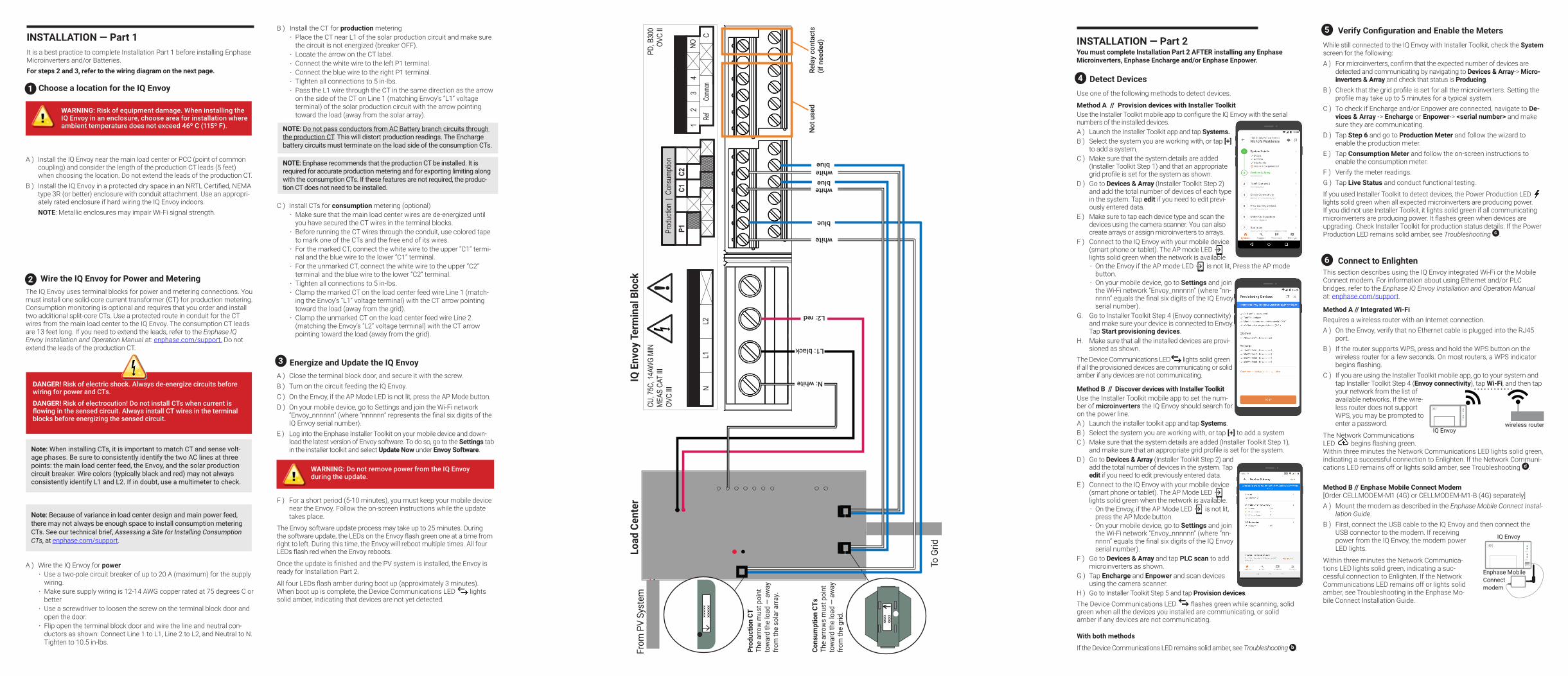
Wire the IQ Envoy for Power and MeteringThe IQ Envoy uses terminal blocks for power and metering connections. You must install one solid-core current transformer (CT) for production metering. Consumption monitoring is optional and requires that you order and install two additional split-core CTs. Use a protected route in conduit for the CT wires from the main load center to the IQ Envoy. The consumption CT leads are 13 feet long. If you need to extend the leads, refer to the Enphase IQ Envoy Installation and Operation Manual at: enphase.com/support. Do not extend the leads of the production CT.
Note: When installing CTs, it is important to match CT and sense volt-age phases. Be sure to consistently identify the two AC lines at three points: the main load center feed, the Envoy, and the solar production circuit breaker. Wire colors (typically black and red) may not always consistently identify L1 and L2. If in doubt, use a multimeter to check.
2
3
DANGER! Risk of electric shock. Always de-energize circuits before wiring for power and CTs.
DANGER! Risk of electrocution! Do not install CTs when current is flowing in the sensed circuit. Always install CT wires in the terminal blocks before energizing the sensed circuit.
B ) Install the CT for production metering• Place the CT near L1 of the solar production circuit and make sure
the circuit is not energized (breaker OFF). • Locate the arrow on the CT label.• Connect the white wire to the left P1 terminal. • Connect the blue wire to the right P1 terminal.• Tighten all connections to 5 in-lbs.• Pass the L1 wire through the CT in the same direction as the arrow
on the side of the CT on Line 1 (matching Envoy’s “L1” voltage terminal) of the solar production circuit with the arrow pointing toward the load (away from the solar array).
C ) Install CTs for consumption metering (optional)• Make sure that the main load center wires are de-energized until
you have secured the CT wires in the terminal blocks.• Before running the CT wires through the conduit, use colored tape
to mark one of the CTs and the free end of its wires.• For the marked CT, connect the white wire to the upper “C1” termi-
nal and the blue wire to the lower “C1” terminal.• For the unmarked CT, connect the white wire to the upper “C2”
terminal and the blue wire to the lower “C2” terminal.• Tighten all connections to 5 in-lbs.• Clamp the marked CT on the load center feed wire Line 1 (match-
ing the Envoy’s “L1” voltage terminal) with the CT arrow pointing toward the load (away from the grid).
• Clamp the unmarked CT on the load center feed wire Line 2 (matching the Envoy’s “L2” voltage terminal) with the CT arrow pointing toward the load (away from the grid).
Energize and Update the IQ EnvoyA ) Close the terminal block door, and secure it with the screw.B ) Turn on the circuit feeding the IQ Envoy.C ) On the Envoy, if the AP Mode LED is not lit, press the AP Mode button. D ) On your mobile device, go to Settings and join the Wi-Fi network
“Envoy_nnnnnn” (where “nnnnnn” represents the final six digits of the IQ Envoy serial number).
E ) Log into the Enphase Installer Toolkit on your mobile device and down-load the latest version of Envoy software. To do so, go to the Settings tab in the installer toolkit and select Update Now under Envoy Software.
F ) For a short period (5-10 minutes), you must keep your mobile device near the Envoy. Follow the on-screen instructions while the update takes place.
The Envoy software update process may take up to 25 minutes. During the software update, the LEDs on the Envoy flash green one at a time from right to left. During this time, the Envoy will reboot multiple times. All four LEDs flash red when the Envoy reboots.
Once the update is finished and the PV system is installed, the Envoy is ready for Installation Part 2.
All four LEDs flash amber during boot up (approximately 3 minutes). When boot up is complete, the Device Communications LED lights solid amber, indicating that devices are not yet detected.
WARNING: Do not remove power from the IQ Envoy during the update.
INSTALLATION — Part 1It is a best practice to complete Installation Part 1 before installing Enphase Microinverters and/or Batteries.For steps 2 and 3, refer to the wiring diagram on the next page.
Choose a location for the IQ Envoy
A ) Install the IQ Envoy near the main load center or PCC (point of common coupling) and consider the length of the production CT leads (5 feet) when choosing the location. Do not extend the leads of the production CT.
B ) Install the IQ Envoy in a protected dry space in an NRTL Certified, NEMA type 3R (or better) enclosure with conduit attachment. Use an appropri-ately rated enclosure if hard wiring the IQ Envoy indoors.
NOTE: Metallic enclosures may impair Wi-Fi signal strength.
1
WARNING: Risk of equipment damage. When installing the IQ Envoy in an enclosure, choose area for installation where ambient temperature does not exceed 46º C (115º F).
Note: Because of variance in load center design and main power feed, there may not always be enough space to install consumption metering CTs. See our technical brief, Assessing a Site for Installing Consumption CTs, at enphase.com/support.
Load
Cen
ter
To G
rid
From
PV
Syst
em
Prod
uctio
n CT
The
arro
w m
ust p
oint
to
war
d th
e lo
ad —
aw
ay
from
the
sola
r arra
y.
IQ E
nvoy
Ter
min
al B
lock
Rela
y co
ntac
ts(if
nee
ded)
L1: black
L2: red
N: white
white
blue
whiteblue
Not
use
d
whiteblue
Cons
umpt
ion
CTs
The
arro
ws
mus
t poi
nt
tow
ard
the
load
— a
way
fro
m th
e gr
id.
P1C1
C21
23
4NO
Ref
Comm
onC
Digit
al Inp
utRe
lay
PD, B
300
OVC
II
L1L2
N
CU, 7
5C, 1
4AW
G MI
NME
AS C
AT III
OVC
IIIPr
oduc
tion
| Con
sump
tion
Detect DevicesUse one of the following methods to detect devices.
Method A // Provision devices with Installer ToolkitUse the Installer Toolkit mobile app to configure the IQ Envoy with the serial numbers of the installed devices.A ) Launch the Installer Toolkit app and tap Systems.B ) Select the system you are working with, or tap [+]
to add a system. C ) Make sure that the system details are added
(Installer Toolkit Step 1) and that an appropriate grid profile is set for the system as shown.
D ) Go to Devices & Array (Installer Toolkit Step 2) and add the total number of devices of each type in the system. Tap edit if you need to edit previ-ously entered data.
E ) Make sure to tap each device type and scan the devices using the camera scanner. You can also create arrays or assign microinverters to arrays.
F ) Connect to the IQ Envoy with your mobile device (smart phone or tablet). The AP mode LED lights solid green when the network is available• On the Envoy if the AP mode LED is not lit, Press the AP mode
button.• On your mobile device, go to Settings and join
the Wi-Fi network “Envoy_nnnnnn” (where “nn-nnnn” equals the final six digits of the IQ Envoy serial number).
G. Go to Installer Toolkit Step 4 (Envoy connectivity) and make sure your device is connected to Envoy. Tap Start provisioning devices.
H. Make sure that all the installed devices are provi-sioned as shown.
The Device Communications LED lights solid green if all the provisioned devices are communicating or solid amber if any devices are not communicating.
Method B // Discover devices with Installer ToolkitUse the Installer Toolkit mobile app to set the num-ber of microinverters the IQ Envoy should search for on the power line.A ) Launch the installer toolkit app and tap Systems. B ) Select the system you are working with, or tap [+] to add a system C ) Make sure that the system details are added (Installer Toolkit Step 1),
and make sure that an appropriate grid profile is set for the system. D ) Go to Devices & Array (Installer Toolkit Step 2) and
add the total number of devices in the system. Tap edit if you need to edit previously entered data.
E ) Connect to the IQ Envoy with your mobile device (smart phone or tablet). The AP Mode LED lights solid green when the network is available. • On the Envoy, if the AP Mode LED is not lit,
press the AP Mode button.• On your mobile device, go to Settings and join
the Wi-Fi network “Envoy_nnnnnn” (where “nn-nnnn” equals the final six digits of the IQ Envoy serial number).
F ) Go to Devices & Array and tap PLC scan to add microinverters as shown.
G ) Tap Encharge and Enpower and scan devices using the camera scanner.
H ) Go to Installer Toolkit Step 5 and tap Provision devices.The Device Communications LED flashes green while scanning, solid green when all the devices you installed are communicating, or solid amber if any devices are not communicating.
With both methods
If the Device Communications LED remains solid amber, see Troubleshooting b .
Verify Configuration and Enable the Meters While still connected to the IQ Envoy with Installer Toolkit, check the System screen for the following: A ) For microinverters, confirm that the expected number of devices are
detected and communicating by navigating to Devices & Array-> Micro-inverters & Array and check that status is Producing.
B ) Check that the grid profile is set for all the microinverters. Setting the profile may take up to 5 minutes for a typical system.
C ) To check if Encharge and/or Enpower are connected, navigate to De-vices & Array -> Encharge or Enpower-> <serial number> and make sure they are communicating.
D ) Tap Step 6 and go to Production Meter and follow the wizard to enable the production meter.
E ) Tap Consumption Meter and follow the on-screen instructions to enable the consumption meter.
F ) Verify the meter readings. G ) Tap Live Status and conduct functional testing.
If you used Installer Toolkit to detect devices, the Power Production LED lights solid green when all expected microinverters are producing power. If you did not use Installer Toolkit, it lights solid green if all communicating microinverters are producing power. It flashes green when devices are upgrading. Check Installer Toolkit for production status details. If the Power Production LED remains solid amber, see Troubleshooting c .
Connect to EnlightenThis section describes using the IQ Envoy integrated Wi-Fi or the Mobile Connect modem. For information about using Ethernet and/or PLC bridges, refer to the Enphase IQ Envoy Installation and Operation Manual at: enphase.com/support.
Method A // Integrated Wi-Fi Requires a wireless router with an Internet connection.A ) On the Envoy, verify that no Ethernet cable is plugged into the RJ45
port. B ) If the router supports WPS, press and hold the WPS button on the
wireless router for a few seconds. On most routers, a WPS indicator begins flashing.
C ) If you are using the Installer Toolkit mobile app, go to your system and tap Installer Toolkit Step 4 (Envoy connectivity), tap Wi-Fi, and then tap your network from the list of available networks. If the wire-less router does not support WPS, you may be prompted to enter a password.
The Network Communications LED begins flashing green. Within three minutes the Network Communications LED lights solid green, indicating a successful connection to Enlighten. If the Network Communi-cations LED remains off or lights solid amber, see Troubleshooting d .
Method B // Enphase Mobile Connect Modem [Order CELLMODEM-M1 (4G) or CELLMODEM-M1-B (4G) separately]A ) Mount the modem as described in the Enphase Mobile Connect Instal-
lation Guide.B ) First, connect the USB cable to the IQ Envoy and then connect the
USB connector to the modem. If receiving power from the IQ Envoy, the modem power LED lights.
Within three minutes the Network Communica-tions LED lights solid green, indicating a suc-cessful connection to Enlighten. If the Network Communications LED remains off or lights solid amber, see Troubleshooting in the Enphase Mo-bile Connect Installation Guide.
4
6
wireless routerIQ Envoy
Enphase Mobile Connectmodem
IQ Envoy
5INSTALLATION — Part 2You must complete Installation Part 2 AFTER installing any Enphase Microinverters, Enphase Encharge and/or Enphase Enpower.
NOTE: Do not pass conductors from AC Battery branch circuits through the production CT. This will distort production readings. The Encharge battery circuits must terminate on the load side of the consumption CTs.
NOTE: Enphase recommends that the production CT be installed. It is required for accurate production metering and for exporting limiting along with the consumption CTs. If these features are not required, the produc-tion CT does not need to be installed.