FCC RF Tes t Re · SPORTON INT TEL : 86-0512-FAX : 86-0512 FCC ID : SRQ AP EQ BR M FC ST CL The p...
30
SPORTON INT TEL : 86-0512- FAX : 86-0512 FCC ID : SRQ AP EQ BR M FC ST CL The p SPOR has b and s The te appro repro Revi Ap TERNATIONAL -5790-0158 -5790-0958 -ZTEN9518 FCC RF PPLICANT QUIPMEN RAND NA ODEL NA CC ID T ANDARD LASSIFICA product was RTON INTER been evaluat shown comp est results i oval of SPO oduced exce iewed by: Jo proved by: SP No. 3-2, P L (KUNSHAN) I F Test Rep FCC T T ME ME D A TION s received on RNATIONAL ted in accor pliance with n this repor ORTON INT ept in full. oseph Lin / Jones Tsai PORTON PingXiang NC. port C RF : ZTE CO : CDMA/ ZTE : N9518 : SRQ-ZT : FCC 47 : PCS Li n Mar. 30, 20 L (SHENZHE rdance with the applica rt apply excl ERNATIONA Supervisor / Manager N INTERN g Road, Ku Tes ORPORA T /LTE Multi TEN9518 7 CFR Part censed Tr 015 and tes EN) INC., wo the proced able technic lusively to t AL (SHENZ NATIONA unshan, J t Re TION -Mode Dig t 2, and 90 ransmitter ting was co ould like to d ures given al standards he tested m HEN) INC., AL (KUNS iangsu Pr Page Numb Report Issu Report Vers R port gital Mobil 0(S) r Held to E ompleted on declare that in ANSI / TIA s. odel / samp the test re SHAN) IN rovince, P . ber : 1 o ued Date : Ma sion : Re Report No. : le Phone Ear (PCE) n Apr. 20, 20 the tested A / EIA-603- ple. Without eport shall NC. . R. China of 30 ay 11, 2015 ev. 01 FW533001A 15. We, sample -C-2004 written not be A
Transcript of FCC RF Tes t Re · SPORTON INT TEL : 86-0512-FAX : 86-0512 FCC ID : SRQ AP EQ BR M FC ST CL The p...

SPORTON INT
TEL : 86-0512-
FAX : 86-0512
FCC ID : SRQ
AP
EQ
BR
M
FC
ST
CL
The p
SPOR
has b
and s
The te
appro
repro
Revi
Ap
TERNATIONAL
-5790-0158
-5790-0958
-ZTEN9518
FCC RF
PPLICANT
QUIPMEN
RAND NA
ODEL NA
CC ID
TANDARD
LASSIFICA
product was
RTON INTER
been evaluat
shown comp
est results i
oval of SPO
oduced exce
iewed by: Jo
proved by:
SPNo. 3-2, P
L (KUNSHAN) I
F Test Rep
FCC
T
T
ME
ME
D
ATION
s received on
RNATIONAL
ted in accor
pliance with
n this repor
ORTON INT
ept in full.
oseph Lin /
Jones Tsai
PORTONPingXiang
NC.
port
C RF
: ZTE CO
: CDMA/
ZTE
: N9518
: SRQ-ZT
: FCC 47
: PCS Li
n Mar. 30, 20
L (SHENZHE
rdance with
the applica
rt apply excl
ERNATIONA
Supervisor
/ Manager
N INTERNg Road, Ku
Tes
ORPORAT
/LTE Multi
TEN9518
7 CFR Part
censed Tr
015 and tes
EN) INC., wo
the proced
able technic
lusively to t
AL (SHENZ
NATIONAunshan, J
t Re
TION
-Mode Dig
t 2, and 90
ransmitter
ting was co
ould like to d
ures given
al standards
he tested m
HEN) INC.,
AL (KUNSJiangsu Pr
Page Numb
Report Issu
Report Vers
R
port
gital Mobil
0(S)
r Held to E
ompleted on
declare that
in ANSI / TIA
s.
odel / samp
the test re
SHAN) INrovince, P.
ber : 1 o
ued Date : Ma
sion : Re
Report No. :
le Phone
Ear (PCE)
n Apr. 20, 20
the tested
A / EIA-603-
ple. Without
eport shall
NC. P. R. China
of 30
ay 11, 2015
ev. 01
FW533001A
15. We,
sample
-C-2004
written
not be
A

SPORTON INTERNATIONAL (KUNSHAN) INC. Page Number : 2 of 30
TEL : 86-0512-5790-0158 Report Issued Date : May 11, 2015
FAX : 86-0512-5790-0958 Report Version : Rev. 01
FCC ID : SRQ-ZTEN9518
FCC RF Test Report Report No. : FW533001A
TABLE OF CONTENTS
REVISION HISTORY .......................................................................................................................................... 3
SUMMARY OF TEST RESULT ......................................................................................................................... 4
1 GENERAL DESCRIPTION .......................................................................................................................... 5 1.1 Applicant ............................................................................................................................................ 5 1.2 Manufacturer ..................................................................................................................................... 5 1.3 Feature of Equipment Under Test ..................................................................................................... 5 1.4 Product Specification of Equipment Under Test ............................................................................... 5 1.5 Modification of EUT ........................................................................................................................... 6 1.6 Maximum Frequency Tolerance and Emission Designator .............................................................. 6 1.7 Testing Site ....................................................................................................................................... 6 1.8 Applied Standards ............................................................................................................................. 6
2 TEST CONFIGURATION OF EQUIPMENT UNDER TEST ........................................................................ 7 2.1 Test Mode.......................................................................................................................................... 7 2.2 Connection Diagram of Test System ................................................................................................ 8 2.3 Support Unit used in test configuration and system .......................................................................... 8 2.4 Measurement Results Explanation Example .................................................................................... 9
3 TEST RESULT ........................................................................................................................................... 10 3.1 Conducted Output Power Measurement ......................................................................................... 10 3.2 99% Occupied Bandwidth and 26dB Bandwidth Measurement...................................................... 12 3.3 Emissions Mask Measurement ....................................................................................................... 17 3.4 Emissions Mask – Out Of Band Emissions Measurement .............................................................. 19 3.5 Field Strength of Spurious Radiation Measurement ....................................................................... 23 3.6 Frequency Stability Measurement ................................................................................................... 26
4 LIST OF MEASURING EQUIPMENT ........................................................................................................ 29
5 UNCERTAINTY OF EVALUATION ........................................................................................................... 30
APPENDIX A. SETUP PHOTOGRAPHS

SPORTON INTERNATIONAL (KUNSHAN) INC. Page Number : 3 of 30
TEL : 86-0512-5790-0158 Report Issued Date : May 11, 2015
FAX : 86-0512-5790-0958 Report Version : Rev. 01
FCC ID : SRQ-ZTEN9518
FCC RF Test Report Report No. : FW533001A
REVISION HISTORY
REPORT NO. VERSION DESCRIPTION ISSUED DATE
FW533001A Rev. 01 Initial issue of report May 11, 2015

SPORTON INTERNATIONAL (KUNSHAN) INC. Page Number : 4 of 30
TEL : 86-0512-5790-0158 Report Issued Date : May 11, 2015
FAX : 86-0512-5790-0958 Report Version : Rev. 01
FCC ID : SRQ-ZTEN9518
FCC RF Test Report Report No. : FW533001A
SUMMARY OF TEST RESULT
Report
Section FCC Rule Description Limit Result Remark
3.1 §2.1046 Conducted Output Power Reporting only PASS -
3.2 §2.1049
§90.209
99% Occupied Bandwidth
and 26dB Bandwidth Reporting only PASS -
3.3 §2.1051
§90.691
Emission masks –
In-band emissions < 50+10log10(P[Watts]) PASS -
3.4 §2.1051
§90.691
Emission masks –
Out of band emissions < 43+10log10(P[Watts]) PASS -
3.5 §2.1053
§90.691
Field Strength of Spurious
Radiation < 43+10log10(P[Watts]) PASS
Under limit
21.82 dB at
2462.000 MHz
3.6 §2.1055
§90.213
Frequency Stability for Temperature & Voltage
< 2.5 ppm PASS -

SPORTON INTERNATIONAL (KUNSHAN) INC. Page Number : 5 of 30
TEL : 86-0512-5790-0158 Report Issued Date : May 11, 2015
FAX : 86-0512-5790-0958 Report Version : Rev. 01
FCC ID : SRQ-ZTEN9518
FCC RF Test Report Report No. : FW533001A
1 General Description
1.1 Applicant
ZTE CORPORATION
ZTE Plaza, Keji Road South, Hi-Tech, Industrial Park, Nanshan District, Shenzhen, Guangdong,
518057, P. R. China
1.2 Manufacturer
ZTE CORPORATION
ZTE Plaza, Keji Road South, Hi-Tech, Industrial Park, Nanshan District, Shenzhen, Guangdong,
518057, P. R. China
1.3 Feature of Equipment Under Test
Product Feature & Specification
Equipment CDMA/LTE Multi-Mode Digital Mobile Phone
Brand Name ZTE
Model Name N9518
FCC ID SRQ-ZTEN9518
EUT supports Radios application CDMA/EV-DO/LTE/WLAN 2.4GHz 802.11b/g/n HT20/ Bluetooth v3.0+EDR/Bluetooth v4.0 LE
MEID Code Conducted: 99000609680276 Radiated: 99000609680631
HW Version cwxA
SW Version N9518V1.0.0B01
EUT Stage Identical Prototype
1.4 Product Specification of Equipment Under Test
Product Specification subjective to this standard
Tx Frequency CDMA2000 BC10 : 817.9 MHz ~ 823.1 MHz Rx Frequency CDMA2000 BC10 : 862.9 MHz ~ 868.1 MHz Maximum Output Power to Antenna CDMA2000 BC10 : 23.81 dBm Antenna Type Fixed Internal Antenna
Type of Modulation CDMA2000 1xRTT : QPSK CDMA2000 1xEV-DO : 8PSK
Remark: This test report recorded only product characteristics and test results of PCS Licensed
Transmitter Held to Ear (PCE).

SPORTON INTERNATIONAL (KUNSHAN) INC. Page Number : 6 of 30
TEL : 86-0512-5790-0158 Report Issued Date : May 11, 2015
FAX : 86-0512-5790-0958 Report Version : Rev. 01
FCC ID : SRQ-ZTEN9518
FCC RF Test Report Report No. : FW533001A
1.5 Modification of EUT
No modifications are made to the EUT during all test items.
1.6 Maximum Frequency Tolerance and Emission Designator
FCC Rule System Type of
Modulation
Frequency
Tolerance
(ppm)
Emission
Designator
Part 90S CDMA2000 BC10 1xRTT QPSK 0.0500 ppm 1M28F9W
1.7 Testing Site
Test Site SPORTON INTERNATIONAL (KUNSHAN) INC.
Test Site Location
No. 3-2, PingXiang Road, Kunshan, Jiangsu Province, P. R. China
TEL: +86-0512-5790-0158
FAX: +86-0512-5790-0958
Test Site No. Sporton Site No. FCC Registration No.
TH01-KS 03CH02-KS 418269
Note: The test site complies with ANSI C63.4 2009 requirement.
1.8 Applied Standards
According to the specifications of the manufacturer, the EUT must comply with the requirements of the
following standards:
Preliminary Guidance for Receiving Applications for Certification of 3G Device. May 9, 2006.
FCC 47 CFR Part 2, 90
ANSI / TIA / EIA-603-C-2004
Remark:
1. All test items were verified and recorded according to the standards and without any deviation
during the test.
2. This EUT has also been tested and complied with the requirements of FCC Part 15, Subpart B,
recorded in a separate test report.

SPORTON INTERNATIONAL (KUNSHAN) INC. Page Number : 7 of 30
TEL : 86-0512-5790-0158 Report Issued Date : May 11, 2015
FAX : 86-0512-5790-0958 Report Version : Rev. 01
FCC ID : SRQ-ZTEN9518
FCC RF Test Report Report No. : FW533001A
2 Test Configuration of Equipment Under Test
2.1 Test Mode
During all testing, EUT is in link mode with base station emulator at maximum power level. The spurious
emission measurements were carried out in semi-anechoic chamber with 3-meter test range, and EUT
is rotated on three test planes to find out the worst emission (X Plane).
Frequency range investigated for radiated emission: 30MHz to 10th harmonic.
Test Modes
Band Radiated TCs Conducted TCs
CDMA2000 BC10 1xRTT Link 1xRTT Link
Note: The maximum RF output power levels are 1xRTT RC1+SO55 mode for CDMA2000 BC10 on
QPSK Link; only these modes were used for all tests.
The conducted power table is as follows:
Conducted Power (*Unit: dBm)
Band CDMA2000 BC10
Channel 476 580 684
Frequency 817.9 820.5 823.1
1xRTT RC1+SO55 23.81 23.80 23.77
1xRTT RC3+SO55 23.78 23.76 23.74
1xRTT RC3 SO32(+ F-SCH) 23.77 23.74 23.73
1xRTT RC3 SO32 (+SCH) 23.76 23.73 23.71
1xEVDO RTAP 153.6Kbps 23.74 23.72 23.70
1xEVDO RETAP 4096Bits 23.80 23.77 23.73
SPORTON INTERNATIONAL (KUNSHAN) INC. Page Number : 8 of 30
TEL : 86-0512-5790-0158 Report Issued Date : May 11, 2015
FAX : 86-0512-5790-0958 Report Version : Rev. 01
FCC ID : SRQ-ZTEN9518
FCC RF Test Report Report No. : FW533001A
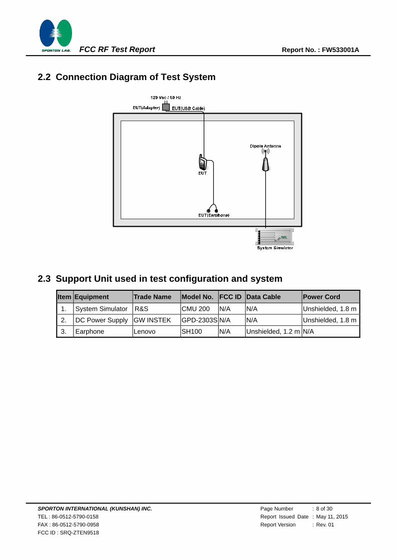
2.2 Connection Diagram of Test System
2.3 Support Unit used in test configuration and system
Item Equipment Trade Name Model No. FCC ID Data Cable Power Cord
1. System Simulator R&S CMU 200 N/A N/A Unshielded, 1.8 m
2. DC Power Supply GW INSTEK GPD-2303S N/A N/A Unshielded, 1.8 m
3. Earphone Lenovo SH100 N/A Unshielded, 1.2 m N/A

SPORTON INTERNATIONAL (KUNSHAN) INC. Page Number : 9 of 30
TEL : 86-0512-5790-0158 Report Issued Date : May 11, 2015
FAX : 86-0512-5790-0958 Report Version : Rev. 01
FCC ID : SRQ-ZTEN9518
FCC RF Test Report Report No. : FW533001A
2.4 Measurement Results Explanation Example
For all conducted test items:
The offset level is set in the spectrum analyzer to compensate the RF cable loss and attenuator factor
between EUT conducted output port and spectrum analyzer. With the offset compensation, the
spectrum analyzer reading level is exactly the EUT RF output level.
Example:
The spectrum analyzer offset is derived from RF cable loss and attenuator factor.
Offset = RF cable loss + attenuator factor.
Following shows an offset computation example with cable loss 5.2 dB and 10dB attenuator.
Offset (dB) = RF cable loss (dB) + attenuator factor (dB).
= 5.2 + 10 = 15.2 (dB)

SPORTON INTERNATIONAL (KUNSHAN) INC. Page Number : 10 of 30
TEL : 86-0512-5790-0158 Report Issued Date : May 11, 2015
FAX : 86-0512-5790-0958 Report Version : Rev. 01
FCC ID : SRQ-ZTEN9518
FCC RF Test Report Report No. : FW533001A
3 Test Result
3.1 Conducted Output Power Measurement
3.1.1 Description of the Conducted Output Power Measurement
A base station simulator was used to establish communication with the EUT. Its parameters were set
to transmit the maximum power on the EUT. The measured power in the radio frequency on the
transmitter output terminals shall be reported.
3.1.2 Measuring Instruments
The measuring equipment is listed in the section 4 of this test report.
3.1.3 Test Procedures
1. The transmitter output port was connected to base station.
2. Set EUT at maximum power through base station.
3. Select lowest, middle, and highest channels for each band and different modulation.
3.1.4 Test Setup

SPORTON INTERNATIONAL (KUNSHAN) INC. Page Number : 11 of 30
TEL : 86-0512-5790-0158 Report Issued Date : May 11, 2015
FAX : 86-0512-5790-0958 Report Version : Rev. 01
FCC ID : SRQ-ZTEN9518
FCC RF Test Report Report No. : FW533001A
3.1.5 Test Result of Conducted Output Power
CDMA 2000 BC10
Modes CDMA 2000 1xRTT
Test Status RC1+SO55
Channel 467 (Low) 580 (Mid) 684 (High)
Frequency (MHz) 817.9 820.5 823.1
Conducted Power (dBm) 23.81 23.80 23.77
Note: Maximum burst average power for CDMA.

SPORTON INTERNATIONAL (KUNSHAN) INC. Page Number : 12 of 30
TEL : 86-0512-5790-0158 Report Issued Date : May 11, 2015
FAX : 86-0512-5790-0958 Report Version : Rev. 01
FCC ID : SRQ-ZTEN9518
FCC RF Test Report Report No. : FW533001A
3.2 99% Occupied Bandwidth and 26dB Bandwidth Measurement
3.2.1 Description of (Occupied) Bandwidth Limitations Measurement
The 99% occupied bandwidth is the width of a frequency band such that, below the lower and above
the upper frequency limits, the mean powers emitted are each equal to a specified percentage 0.5%
of the total mean transmitted power.
The emission bandwidth is defined as the width of the signal between two points, located at the 2
sides of the carrier frequency, outside of which all emissions are attenuated at least 26 dB below the
transmitter power.
3.2.2 Measuring Instruments
The measuring equipment is listed in the section 4 of this test report.
3.2.3 Test Procedures
1. The EUT was connected to Spectrum Analyzer and Base Station via power divider.
2. The 99% and 26 dB occupied bandwidth (BW) of the middle channel for the highest RF powers
were measured.
3.2.4 Test Setup

SPORTON INTERNATIONAL (KUNSHAN) INC. Page Number : 13 of 30
TEL : 86-0512-5790-0158 Report Issued Date : May 11, 2015
FAX : 86-0512-5790-0958 Report Version : Rev. 01
FCC ID : SRQ-ZTEN9518
FCC RF Test Report Report No. : FW533001A
3.2.5 Test Result of 99% Occupied Bandwidth and 26dB Bandwidth
CDMA2000 BC10
Test Mode CDMA 2000 1xRTT
Test Status RC1+SO55
Channel 476 (Low) 580 (Mid) 684 (High)
Frequency (MHz) 817.9 820.5 823.1
99% OBW (MHz) 1.275 1.275 1.275
26dB BW (MHz) 1.435 1.435 1.430
SPORTON INTERNATIONAL (KUNSHAN) INC. Page Number : 14 of 30
TEL : 86-0512-5790-0158 Report Issued Date : May 11, 2015
FAX : 86-0512-5790-0958 Report Version : Rev. 01
FCC ID : SRQ-ZTEN9518
FCC RF Test Report Report No. : FW533001A
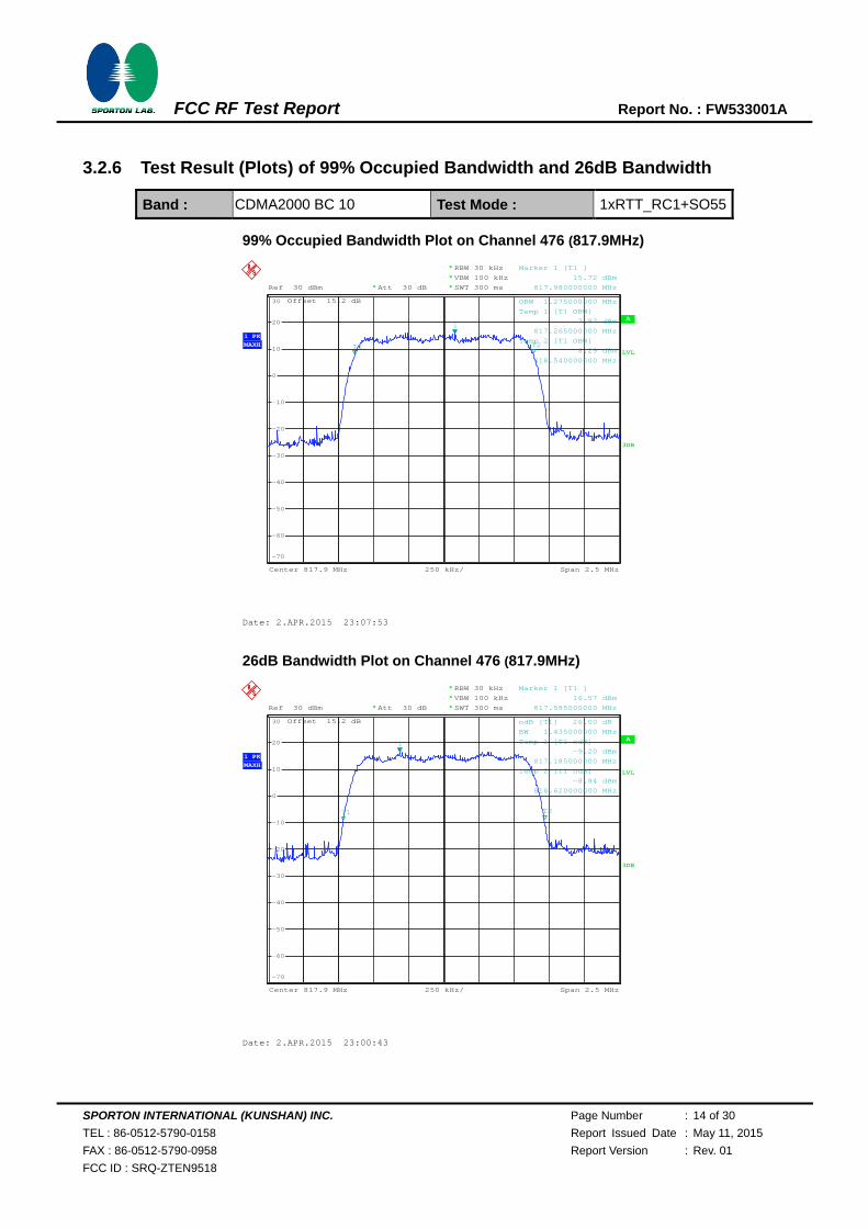
3.2.6 Test Result (Plots) of 99% Occupied Bandwidth and 26dB Bandwidth
Band : CDMA2000 BC 10 Test Mode : 1xRTT_RC1+SO55
99% Occupied Bandwidth Plot on Channel 476 (817.9MHz)
26dB Bandwidth Plot on Channel 476 (817.9MHz)
A
Offset 15.2 dB
LVL
Att 30 dB **Ref 30 dBm
1 PKMAXH
250 kHz/Center 817.9 MHz Span 2.5 MHz
*
*
3DB
RBW 30 kHz
VBW 100 kHz
SWT 300 ms*
-70
-60
-50
-40
-30
-20
-10
0
10
20
30
1
Marker 1 [T1 ]
15.72 dBm
817.980000000 MHz
OBW 1.275000000 MHz
T1
Temp 1 [T1 OBW]
7.87 dBm
817.265000000 MHz
T2Temp 2 [T1 OBW]
8.29 dBm
818.540000000 MHz
Date: 2.APR.2015 23:07:53
A
Offset 15.2 dB
LVL
Att 30 dB **Ref 30 dBm
Center 817.9 MHz Span 2.5 MHz250 kHz/
*
3DB
RBW 30 kHz*VBW 100 kHz
SWT 300 ms*
1 PKMAXH
-70
-60
-50
-40
-30
-20
-10
0
10
20
30
1
Marker 1 [T1 ]
16.57 dBm
817.585000000 MHz
ndB [T1] 26.00 dB
BW 1.435000000 MHz
T1
Temp 1 [T1 ndB]
-9.20 dBm
817.185000000 MHz
T2
Temp 2 [T1 ndB]
-8.84 dBm
818.620000000 MHz
Date: 2.APR.2015 23:00:43

SPORTON INTERNATIONAL (KUNSHAN) INC. Page Number : 15 of 30
TEL : 86-0512-5790-0158 Report Issued Date : May 11, 2015
FAX : 86-0512-5790-0958 Report Version : Rev. 01
FCC ID : SRQ-ZTEN9518
FCC RF Test Report Report No. : FW533001A
99% Occupied Bandwidth Plot on Channel 580 (820.5MHz)
26dB Bandwidth Plot on Channel 580 (820.5MHz)
A
Offset 15.2 dB
LVL
Att 30 dB **Ref 30 dBm
1 PKMAXH
250 kHz/Center 820.5 MHz Span 2.5 MHz
*
*
3DB
RBW 30 kHz
VBW 100 kHz
SWT 300 ms*
-70
-60
-50
-40
-30
-20
-10
0
10
20
30
1
Marker 1 [T1 ]
16.41 dBm
820.740000000 MHz
OBW 1.275000000 MHz
T1
Temp 1 [T1 OBW]
7.60 dBm
819.865000000 MHz
T2Temp 2 [T1 OBW]
8.38 dBm
821.140000000 MHz
Date: 2.APR.2015 23:06:56
A
Offset 15.2 dB
LVL
Att 30 dB **Ref 30 dBm
1 PKMAXH
250 kHz/Center 820.5 MHz Span 2.5 MHz
*
*
3DB
RBW 30 kHz
VBW 100 kHz
SWT 300 ms*
-70
-60
-50
-40
-30
-20
-10
0
10
20
30
1
Marker 1 [T1 ]
16.57 dBm
821.030000000 MHz
ndB [T1] 26.00 dB
BW 1.435000000 MHz
T1
Temp 1 [T1 ndB]
-9.36 dBm
819.785000000 MHz
T2
Temp 2 [T1 ndB]
-9.36 dBm
821.220000000 MHz
Date: 2.APR.2015 23:01:24

SPORTON INTERNATIONAL (KUNSHAN) INC. Page Number : 16 of 30
TEL : 86-0512-5790-0158 Report Issued Date : May 11, 2015
FAX : 86-0512-5790-0958 Report Version : Rev. 01
FCC ID : SRQ-ZTEN9518
FCC RF Test Report Report No. : FW533001A
99% Occupied Bandwidth Plot on Channel 684 (823.1MHz)
26dB Bandwidth Plot on Channel 684 (823.1MHz)
A
Offset 15.2 dB
LVL
Att 30 dB **Ref 30 dBm
1 PKMAXH
250 kHz/Center 823.1 MHz Span 2.5 MHz
*
*
3DB
RBW 30 kHz
VBW 100 kHz
SWT 300 ms*
-70
-60
-50
-40
-30
-20
-10
0
10
20
30
1
Marker 1 [T1 ]
17.80 dBm
823.390000000 MHz
OBW 1.275000000 MHz
T1
Temp 1 [T1 OBW]
10.40 dBm
822.465000000 MHz
T2Temp 2 [T1 OBW]
8.71 dBm
823.740000000 MHz
Date: 2.APR.2015 23:03:27
A
Offset 15.2 dB
LVL
Att 30 dB **Ref 30 dBm
1 PKMAXH
250 kHz/Center 823.1 MHz Span 2.5 MHz
*
*
3DB
RBW 30 kHz
VBW 100 kHz
SWT 300 ms*
-70
-60
-50
-40
-30
-20
-10
0
10
20
30
1
Marker 1 [T1 ]
17.92 dBm
823.355000000 MHz
ndB [T1] 26.00 dB
BW 1.430000000 MHz
T1
Temp 1 [T1 ndB]
-7.52 dBm
822.390000000 MHz
T2
Temp 2 [T1 ndB]
-8.53 dBm
823.820000000 MHz
Date: 2.APR.2015 23:02:08

SPORTON INTERNATIONAL (KUNSHAN) INC. Page Number : 17 of 30
TEL : 86-0512-5790-0158 Report Issued Date : May 11, 2015
FAX : 86-0512-5790-0958 Report Version : Rev. 01
FCC ID : SRQ-ZTEN9518
FCC RF Test Report Report No. : FW533001A
3.3 Emissions Mask Measurement
3.3.1 Description of Emissions Mask Measurement
Equipment used in this licensed to EA or non-EA systems shall comply with the emission mask provisions of FCC
Part 90.691.(a)(1)
3.3.2 Measuring Instruments
The measuring equipment is listed in the section 4 of this test report.
3.3.3 Test Procedures
1. The EUT was connected to spectrum analyzer and base station via power divider.
2. The emissions mask of low and high channels for the highest RF powers were measured.
3. The RBW was set 1% of 99% Occupied Bandwidth, and VBW was set 3 times of RBW.
4. The final test results were shown below plots with a correction offset factor including cable loss,
insertion loss of power divider.
3.3.4 Test Setup
SPORTON INTERNATIONAL (KUNSHAN) INC. Page Number : 18 of 30
TEL : 86-0512-5790-0158 Report Issued Date : May 11, 2015
FAX : 86-0512-5790-0958 Report Version : Rev. 01
FCC ID : SRQ-ZTEN9518
FCC RF Test Report Report No. : FW533001A
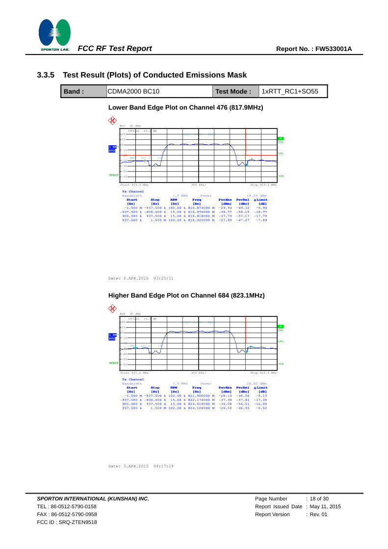
3.3.5 Test Result (Plots) of Conducted Emissions Mask
Band : CDMA2000 BC10 Test Mode : 1xRTT_RC1+SO55
Lower Band Edge Plot on Channel 476 (817.9MHz)
Higher Band Edge Plot on Channel 684 (823.1MHz)
Ref 30 dBm
*
Offset 15.2 dB
1 RMAVG
SPECT
A SGL
LVL
3DB
Start 816.4 MHz Stop 819.4 MHz300 kHz/
-60
-50
-40
-30
-20
-10
0
10
20
Tx Channel Bandwidth 1.5 MHz Power 19.39 dBm Start Stop RBW Freq PwrAbs PwrRel Limit [Hz] [Hz] [Hz] [Hz] [dBm] [dBc] [dB] -1.500 M -937.500 k 100.00 k 816.874000 M -29.94 -49.32 -9.94-937.500 k -900.000 k 15.00 k 816.976000 M -38.77 -58.15 -18.77 900.000 k 937.500 k 15.00 k 818.818000 M -37.79 -57.17 -17.79 937.500 k 1.500 M 100.00 k 818.920000 M -27.89 -47.27 -7.89
SWP 100 of 100
Start Stop RBW Freq PwrAbs PwrRel Limit [Hz] [Hz] [Hz] [Hz] [dBm] [dBc] [dB] -1.500 M -937.500 k 100.00 k 816.874000 M -29.94 -49.32 -9.94-937.500 k -900.000 k 15.00 k 816.976000 M -38.77 -58.15 -18.77 900.000 k 937.500 k 15.00 k 818.818000 M -37.79 -57.17 -17.79 937.500 k 1.500 M 100.00 k 818.920000 M -27.89 -47.27 -7.89
LIMIT CHECK PASS
Date: 3.APR.2015 03:25:11
Ref 30 dBm
*
Offset 15.2 dB
1 RMAVG
SPECT
A SGL
LVL
3DB
Start 821.6 MHz Stop 824.6 MHz300 kHz/
-60
-50
-40
-30
-20
-10
0
10
20
Tx Channel Bandwidth 1.5 MHz Power 20.43 dBm Start Stop RBW Freq PwrAbs PwrRel Limit [Hz] [Hz] [Hz] [Hz] [dBm] [dBc] [dB] -1.500 M -937.500 k 100.00 k 821.900000 M -28.13 -48.56 -8.13-937.500 k -900.000 k 15.00 k 822.176000 M -37.38 -57.81 -17.38 900.000 k 937.500 k 15.00 k 824.018000 M -36.08 -56.51 -16.08 937.500 k 1.500 M 100.00 k 824.108000 M -26.50 -46.93 -6.50
SWP 100 of 100
Start Stop RBW Freq PwrAbs PwrRel Limit [Hz] [Hz] [Hz] [Hz] [dBm] [dBc] [dB] -1.500 M -937.500 k 100.00 k 821.900000 M -28.13 -48.56 -8.13-937.500 k -900.000 k 15.00 k 822.176000 M -37.38 -57.81 -17.38 900.000 k 937.500 k 15.00 k 824.018000 M -36.08 -56.51 -16.08 937.500 k 1.500 M 100.00 k 824.108000 M -26.50 -46.93 -6.50
LIMIT CHECK PASS
Date: 3.APR.2015 04:17:19
SPORTON INTERNATIONAL (KUNSHAN) INC. Page Number : 19 of 30
TEL : 86-0512-5790-0158 Report Issued Date : May 11, 2015
FAX : 86-0512-5790-0958 Report Version : Rev. 01
FCC ID : SRQ-ZTEN9518
FCC RF Test Report Report No. : FW533001A
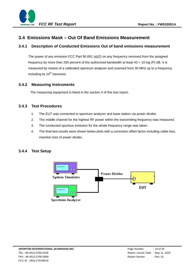
3.4 Emissions Mask – Out Of Band Emissions Measurement
3.4.1 Description of Conducted Emissions Out of band emissions measurement
The power of any emission FCC Part 90.691 (a)(2) on any frequency removed from the assigned
frequency by more than 250 percent of the authorized bandwidth at least 43 + 10 log (P) dB. It is
measured by means of a calibrated spectrum analyzer and scanned from 30 MHz up to a frequency
including its 10th harmonic.
3.4.2 Measuring Instruments
The measuring equipment is listed in the section 4 of this test report.
3.4.3 Test Procedures
1. The EUT was connected to spectrum analyzer and base station via power divider.
2. The middle channel for the highest RF power within the transmitting frequency was measured.
3. The conducted spurious emission for the whole frequency range was taken.
4. The final test results were shown below plots with a correction offset factor including cable loss,
insertion loss of power divider.
3.4.4 Test Setup

SPORTON INTERNATIONAL (KUNSHAN) INC. Page Number : 20 of 30
TEL : 86-0512-5790-0158 Report Issued Date : May 11, 2015
FAX : 86-0512-5790-0958 Report Version : Rev. 01
FCC ID : SRQ-ZTEN9518
FCC RF Test Report Report No. : FW533001A
3.4.5 Test Result (Plots) of Conducted Emission
Band : CDMA2000 BC10 Test Mode : 1xRTT_RC1+SO55
Conducted Emission Plot between on Channel 476 (817.9MHz)
Ref 0 dBm
Offset 15.2 dB
1MAXH
SPUEM
A
LVL
3DB
Start 30 MHz Stop 12.75 GHz1.272 GHz/
-90
-80
-70
-60
-50
-40
-30
-20
-10
Start Stop RBW Freq PwrAbs Limit [Hz] [Hz] [Hz] [Hz] [dBm] [dB] 30.000 M 813.250 M 100.00 k 529.321875 M -72.99 -59.99 827.750 M 1.000 G 100.00 k 889.587750 M -72.73 -59.73 1.000 G 3.000 G 100.00 k 1.636000 G -65.34 -52.34 3.000 G 7.000 G 100.00 k 3.272000 G -69.87 -56.87 7.000 G 10.000 G 100.00 k 9.695500 G -71.28 -58.28 10.000 G 12.750 G 100.00 k 11.603250 G -71.44 -58.44
LIMIT CHECK PASS_SPULIN_
Date: 3.APR.2015 01:50:20

SPORTON INTERNATIONAL (KUNSHAN) INC. Page Number : 21 of 30
TEL : 86-0512-5790-0158 Report Issued Date : May 11, 2015
FAX : 86-0512-5790-0958 Report Version : Rev. 01
FCC ID : SRQ-ZTEN9518
FCC RF Test Report Report No. : FW533001A
Conducted Emission Plot between on Channel 580 (820.5MHz)
Ref 0 dBm
Offset 15.2 dB
1MAXH
SPUEM
A
LVL
3DB
Start 30 MHz Stop 12.75 GHz1.272 GHz/
-90
-80
-70
-60
-50
-40
-30
-20
-10
Start Stop RBW Freq PwrAbs Limit [Hz] [Hz] [Hz] [Hz] [dBm] [dB] 30.000 M 813.250 M 100.00 k 90.701875 M -73.61 -60.61 827.750 M 1.000 G 100.00 k 864.869875 M -73.72 -60.72 1.000 G 3.000 G 100.00 k 1.642000 G -66.62 -53.62 3.000 G 7.000 G 100.00 k 3.282000 G -70.31 -57.31 7.000 G 10.000 G 100.00 k 7.901500 G -71.35 -58.35 10.000 G 12.750 G 100.00 k 10.088000 G -71.78 -58.78
LIMIT CHECK PASS_SPULIN_
Date: 3.APR.2015 02:19:29

SPORTON INTERNATIONAL (KUNSHAN) INC. Page Number : 22 of 30
TEL : 86-0512-5790-0158 Report Issued Date : May 11, 2015
FAX : 86-0512-5790-0958 Report Version : Rev. 01
FCC ID : SRQ-ZTEN9518
FCC RF Test Report Report No. : FW533001A
Conducted Emission Plot between on Channel 684 (823.1MHz)
Ref 0 dBm
Offset 15.2 dB
1MAXH
SPUEM
A
LVL
3DB
Start 30 MHz Stop 12.75 GHz1.272 GHz/
-90
-80
-70
-60
-50
-40
-30
-20
-10
Start Stop RBW Freq PwrAbs Limit [Hz] [Hz] [Hz] [Hz] [dBm] [dB] 30.000 M 813.250 M 100.00 k 637.802000 M -74.69 -61.69 827.750 M 1.000 G 100.00 k 888.640375 M -73.81 -60.81 1.000 G 3.000 G 100.00 k 1.647000 G -67.25 -54.25 3.000 G 7.000 G 100.00 k 3.076000 G -71.50 -58.50 7.000 G 10.000 G 100.00 k 9.182500 G -71.58 -58.58 10.000 G 12.750 G 100.00 k 10.383625 G -70.57 -57.57
LIMIT CHECK PASS_SPULIN_
Date: 3.APR.2015 02:20:20

SPORTON INTERNATIONAL (KUNSHAN) INC. Page Number : 23 of 30
TEL : 86-0512-5790-0158 Report Issued Date : May 11, 2015
FAX : 86-0512-5790-0958 Report Version : Rev. 01
FCC ID : SRQ-ZTEN9518
FCC RF Test Report Report No. : FW533001A
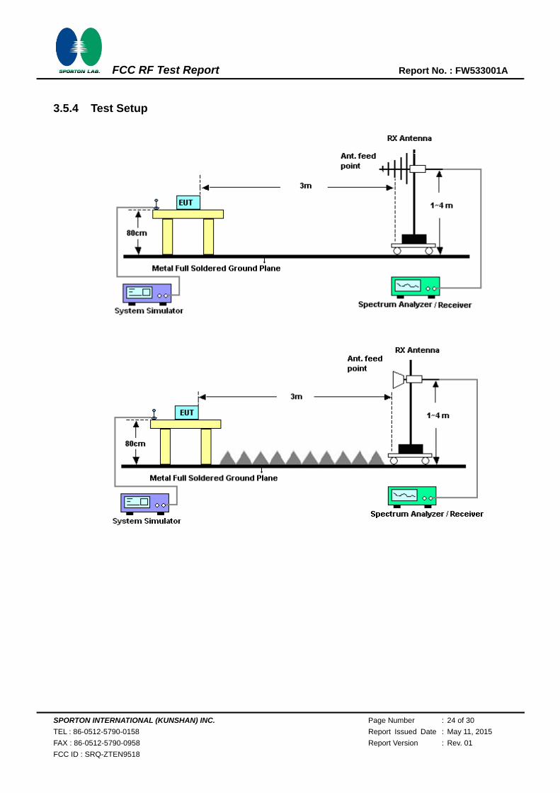
3.5 Field Strength of Spurious Radiation Measurement
3.5.1 Description of Field Strength of Spurious Radiated Measurement
The radiated spurious emission was measured by substitution method according to ANSI / TIA /
EIA-603-C-2004. The power of any emission FCC Part 90.691 on any frequency removed from the
assigned frequency by more than 250 percent of the authorized bandwidth at least 43 + 10 log (P) dB.
The spectrum is scanned from 30 MHz up to a frequency including its 10th harmonic.
The power of any emission outside of the authorized operating frequency ranges must be attenuated
below the transmitter power (P) by a factor of at least 43+10log10(P[Watts]) dB. The spectrum is
scanned from 30 MHz up to a frequency including its 10th harmonic.
3.5.2 Measuring Instruments
The measuring equipment is listed in the section 4 of this test report.
3.5.3 Test Procedures
1. The EUT was placed on a rotatable wooden table with 0.8 meter about ground.
2. The EUT was set 3 meters from the receiving antenna, which was mounted on the antenna
tower.
3. The table was rotated 360 degrees to determine the position of the highest spurious emission.
4. The height of the receiving antenna is varied between one meter and four meters to search the
maximum spurious emission for both horizontal and vertical polarizations.
5. Make the measurement with the spectrum analyzer's RBW = 1MHz, VBW = 3MHz, Sweep =
500ms, Taking the record of maximum spurious emission.
6. A horn antenna was substituted in place of the EUT and was driven by a signal generator.
7. Tune the output power of signal generator to the same emission level with EUT maximum
spurious emission.
8. Taking the record of output power at antenna port.
9. Repeat step 7 to step 8 for another polarization.
10. EIRP (dBm) = S.G. Power – Tx Cable Loss + Tx Antenna Gain
11. ERP (dBm) = EIRP - 2.15
12. The RF fundamental frequency should be excluded against the limit line in the operating
frequency band.
13. The limit line is derived from 43 + 10log(P) dB below the transmitter power P(Watts)
= P(W) - [43 + 10log(P)] (dB)
= [30 + 10log(P)] (dBm) - [43 + 10log(P)] (dB)
= -13dBm.
SPORTON INTERNATIONAL (KUNSHAN) INC. Page Number : 24 of 30
TEL : 86-0512-5790-0158 Report Issued Date : May 11, 2015
FAX : 86-0512-5790-0958 Report Version : Rev. 01
FCC ID : SRQ-ZTEN9518
FCC RF Test Report Report No. : FW533001A
3.5.4 Test Setup

SPORTON INTERNATIONAL (KUNSHAN) INC. Page Number : 25 of 30
TEL : 86-0512-5790-0158 Report Issued Date : May 11, 2015
FAX : 86-0512-5790-0958 Report Version : Rev. 01
FCC ID : SRQ-ZTEN9518
FCC RF Test Report Report No. : FW533001A
3.5.5 Test Result of Field Strength of Spurious Radiated
Band : CDMA2000 BC10 Temperature : 21~22°C
Test Mode : 1xRTT_RC1+SO55 Relative Humidity : 41~42%
Test Engineer : Jack Wang Polarization : Horizontal
Remark : Spurious emissions within 30-1000MHz were found more than 20dB below limit line.
Frequency ERP Limit Over SPA S.G. TX Cable TX Antenna Polarization Result
Limit Reading Power loss Gain
( MHz ) ( dBm ) ( dBm ) ( dB ) (dBm) ( dBm ) ( dB ) (dBi) (H/V)
1640 -50.89 -13 -37.89 -53.42 -52.78 1.86 5.90 H Pass
2462 -34.82 -13 -21.82 -49.58 -37.16 2.31 6.80 H Pass
3282 -52.98 -13 -39.98 -65.61 -55.38 2.85 7.40 H Pass
Band : CDMA2000 BC10 Temperature : 21~22°C
Test Mode : 1xRTT_RC1+SO55 Relative Humidity : 41~42%
Test Engineer : Jack Wang Polarization : Vertical
Remark : Spurious emissions within 30-1000MHz were found more than 20dB below limit line.
Frequency ERP Limit Over SPA S.G. TX Cable TX Antenna Polarization Result
Limit Reading Power loss Gain
( MHz ) ( dBm ) ( dBm ) ( dB ) (dBm) ( dBm ) ( dB ) (dBi) (H/V)
1642 -53.37 -13 -40.37 -53.97 -55.26 1.86 5.90 V Pass
2462 -40.11 -13 -27.11 -54.56 -42.45 2.31 6.80 V Pass
3282 -51.39 -13 -38.39 -65.37 -53.79 2.85 7.40 V Pass

SPORTON INTERNATIONAL (KUNSHAN) INC. Page Number : 26 of 30
TEL : 86-0512-5790-0158 Report Issued Date : May 11, 2015
FAX : 86-0512-5790-0958 Report Version : Rev. 01
FCC ID : SRQ-ZTEN9518
FCC RF Test Report Report No. : FW533001A
3.6 Frequency Stability Measurement
3.6.1 Description of Frequency Stability Measurement
The frequency stability shall be measured by variation of ambient temperature and variation of
primary supply voltage to ensure that the fundamental emission stays within the authorized frequency
block. The frequency stability of the transmitter shall be maintained within ±0.00025% (±2.5ppm) of
the center frequency according to FCC Part 90.213.
3.6.2 Measuring Instruments
The measuring equipment is listed in the section 4 of this test report.
3.6.3 Test Procedures for Temperature Variation
1. The EUT was set up in the thermal chamber and connected with the base station.
2. With power OFF, the temperature was decreased to -30°C and the EUT was stabilized for three
hours. Power was applied and the maximum change in frequency was recorded within one
minute.
3. With power OFF, the temperature was raised in 10°C step up to 50°C. The EUT was stabilized
at each step for at least half an hour. Power was applied and the maximum frequency change
was recorded within one minute.
3.6.4 Test Procedures for Voltage Variation
1. The EUT was placed in a temperature chamber at 25±5° C and connected with the base
station.
2. The power supply voltage to the EUT was varied from BEP to 115% of the nominal value
measured at the input to the EUT.
3. The variation in frequency was measured for the worst case.

SPORTON INTERNATIONAL (KUNSHAN) INC. Page Number : 27 of 30
TEL : 86-0512-5790-0158 Report Issued Date : May 11, 2015
FAX : 86-0512-5790-0958 Report Version : Rev. 01
FCC ID : SRQ-ZTEN9518
FCC RF Test Report Report No. : FW533001A
3.6.5 Test Setup
3.6.6 Test Result of Temperature Variation
Band : CDMA2000 BC10 Channel : 580
Test Mode : 1xRTT_RC1+SO55 Limit (ppm) : 2.5
Temperature (°C) Deviation
(ppm) Result
50 0.0146
PASS
40 0.0049
30 0.0500
20(Ref.) 0.0000
10 0.0439
0 0.0012
-10 0.0073
-20 0.0317
-30 0.0402

SPORTON INTERNATIONAL (KUNSHAN) INC. Page Number : 28 of 30
TEL : 86-0512-5790-0158 Report Issued Date : May 11, 2015
FAX : 86-0512-5790-0958 Report Version : Rev. 01
FCC ID : SRQ-ZTEN9518
FCC RF Test Report Report No. : FW533001A
3.6.7 Test Result of Voltage Variation
Band & Channel Mode Voltage(Volt)
Deviation (ppm)
Limit (ppm)
Result
CDMA2000 BC10
CH580 1xRTT_RC1+SO55
4.35 0.0037
2.5 PASS 3.8 0.0378
BEP 0.0061
Note:
1. Normal Voltage = 3.8V. 2. Battery End Point (BEP) = 3.6 V. 3. The manufacturer declared that the EUT could work properly between voltage 3.6V ~ 4.35V.

SPORTON INTERNATIONAL (KUNSHAN) INC. Page Number : 29 of 30
TEL : 86-0512-5790-0158 Report Issued Date : May 11, 2015
FAX : 86-0512-5790-0958 Report Version : Rev. 01
FCC ID : SRQ-ZTEN9518
FCC RF Test Report Report No. : FW533001A
4 List of Measuring Equipment
Instrument Manufacturer Model No. Serial No. CharacteristicsCalibration
Date Test Date Due Date Remark
Spectrum
Analyzer R&S FSP40 100319 9kHz~40GHz Oct. 28, 2014
Apr. 02, 2015~
Apr. 03, 2015 Oct. 27, 2015
Conducted
(TH01-KS)
Thermal
Chamber Ten Billion TTC-B3S TBN-960502 -40~+150°C Oct. 25, 2014
Apr. 02, 2015~
Apr. 03, 2015 Oct. 24, 2015
Conducted
(TH01-KS)
EMI Test Receiver
R&S ESR7 101403 9kHz~7GHz;Max
30dBm Sep. 29, 2014 Apr. 20, 2015 Sep. 28, 2015
Radiation (03CH02-KS)
Spectrum Analyzer
R&S FSV40 101040 10kHz~40GHz;Ma
x 30dBm Sep. 25, 2014 Apr. 20, 2015 Sep. 24, 2015
Radiation (03CH02-KS)
Bilog Antenna TeseQ CBL6112D 37879 30MHz-2GHz Sep. 13, 2014 Apr. 20, 2015 Sep. 12, 2015Radiation
(03CH02-KS)
Double Ridge Horn Antenna
ETS-Lindgren 3117 75957 1GHz~18GHz Nov. 08, 2014 Apr. 20, 2015 Nov. 07, 2015Radiation
(03CH02-KS)
Active Horn Antenna
com-power AHA-118 701030 1GHz~18GHz Nov. 08, 2014 Apr. 20, 2015 Nov. 07, 2015Radiation
(03CH02-KS)
SHF-EHF Horn com-power AH-840 101070 18GHz~40GHz Sep. 04, 2014 Apr. 20, 2015 Sep. 03, 2015Radiation
(03CH02-KS)
Amplifier com-power PA-103A 161069 1kHz ~1000MHz /
32 dB May 04, 2014 Apr. 20, 2015 May 03, 2015
Radiation (03CH02-KS)
Amplifier Agilent 8449B 3008A023841-26.5GHz Gain
30dB Oct. 28, 2014 Apr. 20, 2015 Oct. 27, 2015
Radiation (03CH02-KS)
AC Power Source
Chroma 61601 616010002473 N/A NCR Apr. 20, 2015 NCR Radiation
(03CH02-KS)
Turn Table MF MF7802 N/A 0~360 degree NCR Apr. 20, 2015 NCR Radiation
(03CH02-KS)
Antenna Mast MF MF7802 N/A 1 m~4 m NCR Apr. 20, 2015 NCR Radiation
(03CH02-KS)
SPORTON INTERNATIONAL (KUNSHAN) INC. Page Number : 30 of 30
TEL : 86-0512-5790-0158 Report Issued Date : May 11, 2015
FAX : 86-0512-5790-0958 Report Version : Rev. 01
FCC ID : SRQ-ZTEN9518
FCC RF Test Report Report No. : FW533001A
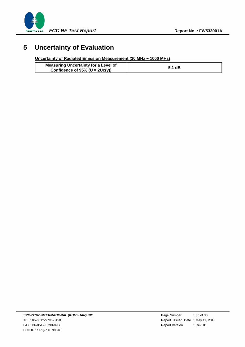
5 Uncertainty of Evaluation
Uncertainty of Radiated Emission Measurement (30 MHz ~ 1000 MHz)
Measuring Uncertainty for a Level of Confidence of 95% (U = 2Uc(y))
5.1 dB


![[COMPLETE] 0512 PRIL Digest Compilation.pdf](https://static.fdocuments.us/doc/165x107/55cf8e60550346703b91810f/complete-0512-pril-digest-compilationpdf.jpg)