FCC Compliance Statement - rugged-cctv.com · PDF fileFCC Compliance Statement ......
173
Transcript of FCC Compliance Statement - rugged-cctv.com · PDF fileFCC Compliance Statement ......


1
FCC Compliance Statement Model Name: Premier 480/ Premier 240 This device complies with Part 15 of the FCC Rules. Operation is Subject to the following two conductions: (1) this device may not cause harmful interference, and (2) this device must accept any interference received, including interference that may cause undesired operations.
WARNING - The partial or whole reproduction of this document is prohibited by law. - Figures for examples in this document may be different from real objects. - The specification and shape of this product may be subject to change due to the enhancement of the quality without prior notice.
CAUTIONS In order to use the product properly, please read carefully all cautions before using the product. Follow the cautions carefully to ensure the safety.
Prerequisites 1. When installing or moving the DVR or peripheral devices or opening their covers,
connect/disconnect cables to/from them properly to avoid electric shock. Connect the power cable to a grounded electrical outlet.
2. When installing the DVR into a power outlet, maintain it can be removed easily. 3. Do not use the DVR around water or in wet places. 4. Because there is a danger of suffocation with the vinyl packaging for the DVR and
peripheral devices, keep them in a location a child can not reach . Installation environment for the DVR
1. Maintain a proper temperature (0˚C ~ 40˚C)/humidity(10% ~ 80%). 2. Install it in a safe place free from external vibration. 3. Install it in a well-ventilated clean place. 4. Install it in a place away from magnetic material to avoid data loss or failure of the hard
drive(s). 5. When the standard rack is not used, it is necessary to secure a space more than 60 cm from
the floor, 50 cm from the ceiling and 20 cm from the side and rear walls using an additional table or structure.
Safe rules for DVR 1. Before installing an additional board or HDD, ensure that the power cable is disconnected
from the DVR. 2. Keep the product away from high-temperature objects such as heaters. 3. Do not use a damaged power cord. 4. Use cables and electrical outlets connected to a ground in order to prevent or minimize
problems due to electromagnetic waves and power surges. 5. Do not touch the power supply device while the power cord is connected. When thepower
cord is connected even though the power is switched off, the electrical current is still flowing internally.

2
6. Do not leave a heavy object on the DVR. 7. Make sure that a conductive object does not fall into the groove made for ventilation. 8. Secure a space large enough for the wiring on the back of the DVR. 9. Use only components described in the guide and do not assemble, repair or revise the
product without permission. If you do not you void the warranty. 10. Incorrect system settings may decrease the performance of certain functions. 11. Stop the system by following the normal procedure defined in the guide. DO NOT JUST
UNPLUG THE DVR. 12. The UPS power supply contains a small amount of harmful material. When the battery is
not mounted properly or is exposed to a heat, water, or electrical-short event, there is a danger of explosion. Keep the battery pack at a place that a child can not reach, and only discard it in a proper place.
Cautions on the lithium battery 1. Exchanging the lithium battery in an improper way can be dangerous. 2. Be sure and dispose of used lithium ion batteries in a safe and environmently-friendly way.
Cautions are classified into warnings and cautions as follows.
Warnings are given when there is a possibility of injury to the user or damage to the product.
Cautions are given when there is a possibility of slight injury to the user or damage to the product.
3
Premier Series
C/O/N/T/E/N/T/S Premier Series
FCC Compliance Statement........................................................................... 1
WARNING....................................................................................................... 1
CAUTIONS...................................................................................................... 1
C/O/N/T/E/N/T/S ............................................................................................. 3
Chapter� Overview ....................................................................................... 6
�-� Product Introduction....................................................................................................6 �-� Main features...............................................................................................................6 �-� Checking components .................................................................................................8
Chapter� Installation and Connection ........................................................ 9
�-� Name and function of each part...................................................................................9 ��-���-��� Front-side touch pad ........................................................................................................ 9 ��-���-��� Back side ....................................................................................................................... 10
�-� Installation and Connection.......................................................................................11 ��-���-��� Basic connection............................................................................................................ 11 ��-���-��� Other device connection ................................................................................................ 12 ��-���-��� Adding HDDs................................................................................................................ 15
Chapter� Operation and Setup tools ......................................................... 19
�-� Front-side Touch Pad ................................................................................................19 �-� Remote control ..........................................................................................................20 �-� Mouse........................................................................................................................22
Chapter� System operation ........................................................................ 23
�-� Starting/stopping the system......................................................................................23 ��-���-��� Starting the system ........................................................................................................ 23 ��-���-��� Stopping the system....................................................................................................... 23
�-� System login..............................................................................................................25 ��-���-��� User account .................................................................................................................. 25 ��-���-��� Login ............................................................................................................................. 25
�-� Monitoring.................................................................................................................27 ��-���-��� Viewing the segmentation screen and automatic switch screen..................................... 27

4
�-� Recording/Playing Audio ..........................................................................................30 ��-���-��� Audio Recording setup .................................................................................................. 30 ��-���-��� Audio Live..................................................................................................................... 32
�-� Viewing the system information and changing the screen settings ...........................33 ��-���-��� Viewing the system information.................................................................................... 33 ��-���-��� Screen brightness control............................................................................................... 35 ��-���-��� Screen contrast control .................................................................................................. 35 ��-���-��� Camera control .............................................................................................................. 35 ��-���-��� TV control ..................................................................................................................... 36 ��-���-��� Language selection ........................................................................................................ 36 ��-���-��� Setting the visibility of the camera title ......................................................................... 37 ��-���-��� Screen border line control.............................................................................................. 37 ��-���-��� Initializing the screen settings ....................................................................................... 38
�-� System logs ...............................................................................................................39 ��-���-��� Log type......................................................................................................................... 39 ��-���-��� Viewing the system logs................................................................................................ 39
�-� Recording ..................................................................................................................43 ��-���-��� Recording type .............................................................................................................. 43 ��-���-��� Recording setup............................................................................................................. 43 ��-���-��� Viewing the recording status ......................................................................................... 43 ��-���-��� Starting/stopping all recordings ..................................................................................... 44 ��-���-��� Watermark..................................................................................................................... 45
�-� Search........................................................................................................................46 ��-���-��� Going to the search mode .............................................................................................. 46 ��-���-��� Selecting a search method ............................................................................................. 47 ��-���-��� Selecting a search tool ................................................................................................... 47 ��-���-��� Multi-channel ................................................................................................................ 50 ��-���-��� Multi-hour ..................................................................................................................... 51 ��-���-��� Multi-day....................................................................................................................... 52
�-� Playback ....................................................................................................................54 ��-���-��� Going to the playback mode .......................................................................................... 54 ��-���-��� Playback and playback speed control ............................................................................ 56 ��-���-��� Playback with segmentation screen ............................................................................... 57 ��-���-��� Audio Playback ............................................................................................................. 59 ��-���-��� Mute .............................................................................................................................. 60 ��-���-��� Smart search .................................................................................................................. 61 ��-���-��� Digital zoom.................................................................................................................. 64 ��-���-��� Simultaneous playback/real-time monitoring ................................................................ 66
�-�� Backup....................................................................................................................67 �-�� PTZ camera control ................................................................................................71
5
��-�����-��� Prerequisites for PTZ function.................................................................................... 71 ��-�����-��� Going to PTZ mode.................................................................................................... 71 ��-�����-��� PTZ control ................................................................................................................ 71
�-�� Manual SPOT.........................................................................................................74
Chapter� System setup................................................................................ 75
�-� Main setup .................................................................................................................75 ��-���-��� Starting the main setup .................................................................................................. 75 ��-���-��� Recording setup............................................................................................................. 76 ��-���-��� Recording schedule ....................................................................................................... 97 ��-���-��� System ......................................................................................................................... 103 ��-���-��� Storage device ............................................................................................................. 116 ��-���-��� NTP ............................................................................................................................. 125 ��-���-��� Advanced..................................................................................................................... 129
�-� App. setup................................................................................................................133 ��-���-��� Going to the App. setup............................................................................................... 133 ��-���-��� PTZ setup .................................................................................................................... 134 ��-���-��� Setting the network...................................................................................................... 138
Chapter� Plus Viewer (Web Monitoring) ............................................... 153
�-� How to access..........................................................................................................153 �-� Description on basic functions ................................................................................155 �-� Audio.......................................................................................................................156 �-� Color Adjust ............................................................................................................156 �-� DVR Network Setting .............................................................................................157 �-� Screen segmentation view .......................................................................................159 �-� Search and Playback................................................................................................162
��-���-��� Selecting a search method ........................................................................................... 163 ��-���-��� Search and playback .................................................................................................... 163 ��-���-��� Playback control .......................................................................................................... 165 ��-���-��� Screen description ....................................................................................................... 165
�-� DVR Setup ..............................................................................................................166
Chapter� Quick Viewer ............................................................................ 167
�-� File playback ...........................................................................................................168 �-� Button description ...................................................................................................169 �-� Version information ................................................................................................169
A/P/P/E/N/D/I/X .......................................................................................... 170
1. PTZ camera protocol ...................................................................... 171
2. Recommended HDD........................................................................ 171

6
3. Recommended USB2.0 device ........................................................ 172
Memory stick....................................................................................................172 2.5’’ Portable USB HDD..................................................................................172 CD-RW, DVD-RW ..........................................................................................172 IEEE1394 device ..............................................................................................172
Chapter� Overview �-�Product Introduction Premier 480/240 are digital image monitoring devices that provide clean images by displaying input images using up to 16 cameras on the screen and recording high-quality digital images at a variety of recording options. It provides various operation methods for the users convenience, including the front touch pad, remote control and mouse, and features a user friendly network function such as the monitoring/system setting at a distance. Both the Premier 480 & 240 provide the same functions, except each max recording frame is 480fps/240fps respectively.
�-�Main features Stable Standalone DVR (Embedded Linux) Video Output
- Loop Output : 16 BNC - Quad Output : 4 BNC - Monitor Output : 1 BNC, 1 VGA, 1 DVI-D - Spot Output : 1 BNC
480fps real time Display / record / play at the same time Record resolution
- NTSC : 352×240, 704×240, 704×480 - PAL : 352×288, 704×288, 704×576
Compression type : MPEG4 (Video) / G.726 (Audio) Backup / Copy – Ethernet, IEEE1394, USB2.0 System operation = front-side Touch pad/ Remote control/ Network/ USB2.0 mouse/
Keyboard control 16 / 8 / 4-channel audio input Various network interfaces
- PSTN, ISDN, Cable Modem, Ethernet, ADSL / DHCP Client Remote system setting (controls overall functions from a remote location) Built-in UPS NTP settings Various record modes
- Auto, Continuous, Event (Sensor, Motion, Sound) Recording Record scheduling Multi-language, automatic e-mail transmission PTZ Control through the RS485/RS422 communication Remote monitoring software/ remote monitoring through web browser / PDA

7
Storage device - Internal storage device : Max. 6HDD, Max 3TB - External storage device : IEEE1394 RAID external storage device

8
�-�Checking components When you unpack the product, ensure that the following accessories are included. 1) Basic components
2) Optional components

9
Chapter� Installation and Connection �-�Name and function of each part The front side of the Premier 480/240 provides a user-friendly touch pad, and the back side includes a variety of interfaces. In addition, they are designed to be mounted on a standard rack, providing a convenient mount using the Rack mounting handle (Left/Right). ��-���-���Front-side touch pad
At the number input mode, the LOG, RECORD, SEARCH, STATUS and ESC buttons work
as the number input buttons. No Name Function 1 POWER System power On/Off 2 LOG System log view or number 1, 2 3 RECORD Start/stop all channel recordings or number 3, 4 4 SEARCH Search recorded images or number 5, 6 5 STATUS View the system information/change the screen settings or number
7, 8 6 ESC Exit the current menu/Move to the upper menu or number 9, 0 7 NUMBER System login and switch On when in number input mode 8 Reverse Play / Fast
Reverse Reverse play/ Fast Reverse
9 Reverse Frame by Frame or TAB
Reverse play by frame
10 Forward Frame by Frame or TAB
Forward play by frame
11 Forward Play / Fast Forward
Forward play / Fast forward
12 SELECT Select item or change the screen sequentially 13 MOVE & DISPLAY Move item or change the display mode 14 REMOTE The red light is turned on when a signal is received from the
remote control 15 NETWORK The blue light is turned on when a connection is made remotely 16 BACKUP For backup, the orange light is turned on 17 HDD With a HDD is in operation, the red light is turned on
10
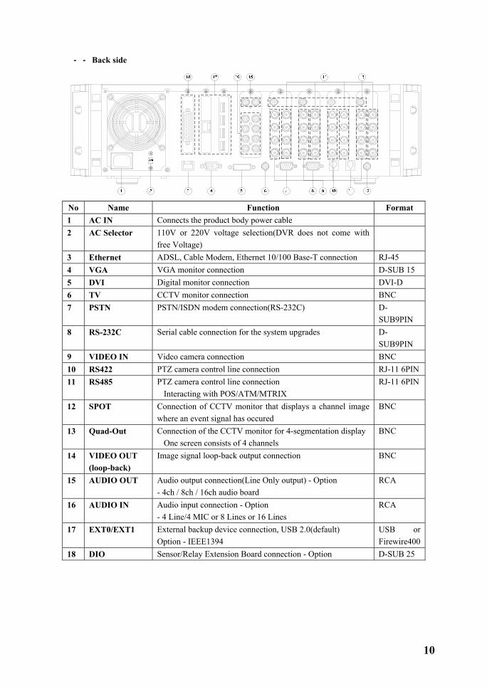
��-���-���Back side
No Name Function Format 1 AC IN Connects the product body power cable 2 AC Selector 110V or 220V voltage selection(DVR does not come with
free Voltage)
3 Ethernet ADSL, Cable Modem, Ethernet 10/100 Base-T connection RJ-45 4 VGA VGA monitor connection D-SUB 15 5 DVI Digital monitor connection DVI-D 6 TV CCTV monitor connection BNC 7 PSTN PSTN/ISDN modem connection(RS-232C) D-
SUB9PIN 8 RS-232C Serial cable connection for the system upgrades D-
SUB9PIN 9 VIDEO IN Video camera connection BNC 10 RS422 PTZ camera control line connection RJ-11 6PIN 11 RS485 PTZ camera control line connection
�Interacting with POS/ATM/MTRIX RJ-11 6PIN
12 SPOT Connection of CCTV monitor that displays a channel image where an event signal has occured
BNC
13 Quad-Out Connection of the CCTV monitor for 4-segmentation display �One screen consists of 4 channels
BNC
14 VIDEO OUT (loop-back)
Image signal loop-back output connection BNC
15 AUDIO OUT Audio output connection(Line Only output) - Option - 4ch / 8ch / 16ch audio board
RCA
16 AUDIO IN Audio input connection - Option - 4 Line/4 MIC or 8 Lines or 16 Lines
RCA
17 EXT0/EXT1 External backup device connection, USB 2.0(default) Option - IEEE1394
USB or Firewire400
18 DIO Sensor/Relay Extension Board connection - Option D-SUB 25
11
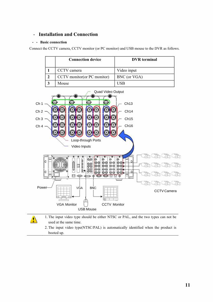
�-�Installation and Connection ��-���-���Basic connection
Connect the CCTV camera, CCTV monitor (or PC monitor) and USB mouse to the DVR as follows.
Connection device DVR terminal
1 CCTV camera Video input 2 CCTV monitor(or PC monitor) BNC (or VGA) 3 Mouse USB
Quad Video Output
Ch13
CCTV Camera
CCTV MonitorVGA MonitorUSB Mouse
Power
Ch14
Ch15
Ch16
Ch 1
Ch 2
Ch 3
Ch 4
Loop-through Ports
Video Inputs
1. The input video type should be either NTSC or PAL, and the two types can not be
used at the same time. 2. The input video type(NTSC/PAL) is automatically identified when the product is
booted up.

12
��-���-���Other device connection
Connect the PTZ control cables, audio input/output, network and sensors, as shown in the following figure.
Connection device DVR terminal
1 PTZ camera RS422 or RS485 2 SPOT monitor(CCTV monitor) BNC 3 DVI monitor DVI 4 Audio input / Audio output RCA Audio input / Audio output 5 LAN Cable Ethernet 6 Sensor/Relay extension board DIO
(1)PTZ camera
� For a PTZ camera, connect the control cable of the PTZ camera to the RS422 or RS485 connector. Use RJ-11 6PIN Type for the RS422 and RS485, PIN configuration is as follows.
PIN 1 2 3 4 5 6 RS422 GND T+ T- R+ R- GND RS485 GND TR+ TR- TR+ TR- GND
(2)SPOT monitor The SPOT monitor is the CCTV monitor in which to see the event occurrence screen. The SPOT monitor displays images of the channel where an event (motion, sensor or sound) is detected in the full screen mode. The interval of the event check is one second, the last detected image is displayed in the full screen mode if events are detected on several channels at the same time. (3)Audio input/output The audio card is optional, providing three types of audio channels including 16-channel, 8-channel and 4-channel. The 4-channel audio board supports 4 microphone inputs, 4 line inputs and 2 audio outputs. You have to choose either the line input or microphone input for the 4-channel audio board, and the line input and microphone input can not be used at the same time once one of them is chosen.

13
The 8-channel audio board supports 8 audio inputs and 2 audio outputs. The 16-channel audio board supports 16 audio inputs and 1 audio output. - To set the audio board, go to {Main setting} → {System} → {11. Audio board type}.
- When you select the 16-channel audio board, the red connection line at the 16-channel audio cable under {1-3 Checking components} → {2.Configuring options} means the odd channel.
(4)Sensor/relay extension board Connect the sensor/relay extension board to the DIO connector in the back side of the equipment, using the D-SUB 25 type extension cable. A)External sensor connection option The sensor/relay extension board includes 16 sensor inputs and 4 relay outputs.
Sensor / relay extension board
Sensor input terminal Upper: 1~8 Lower: 9~16

14
Connection of external sensors � Connect the output of the external sensor to the input terminal marked S1~S16 and GND of the
sensor/relay extension board. � You don’t have to consider the channel number when connecting each input terminal.
Example - When connecting 3 external sensors, Connect each sensor input terminal and external sensor as follows.
External sensor Input terminal GRD terminal
Sensor1 S1 GND Sensor 2 S3 GND Sensor 3 S6 GND
The type of a sensor is divided into NC (Normal Close) and NO(Normal Open), and please refer to {5-1-2 Data setup} {(7)Event setup} {(B)SENSOR} for its set up. NC (Normal Close): It normally stays on the closed mode although it is opened once a signal is received. NO (Normal Open): It normally stays on the opened mode although it is closed once a signal is received.
B)Relay connection Relay output terminal
� Give the alarm signal to an external alarm device by connecting the relay output to the external alarm
device such as an alarm light. � Select a terminal from each pair of output terminals marked with Rx_COM and Rx on the output
terminal, and connect it to an external alarm device. Example - When connecting 4 external alarm devices, Make connections between relay output terminals and external alarm devices as follows.
External alarm device
Output terminal GND terminal
Relay 1 R1 R1_COM Relay 2 R2 R2_COM Relay 3 R3 R3_COM Relay 4 R4 R4_COM
The type of a relay is divided into NC(Normal Close) and NO(Normal Open), and please refer to {5-1-2 Data setup} {(8)Alarm Out} {(E)Relay} for its setup. NC (Normal Close): It normally stays on the closed mode although it is opened once a signal is received. NO (Normal Open): It normally stays on the opened mode although it is closed once a signal is received.

15
��-���-���Adding HDDs
This system allows you to mount up to 6 hard drives, and you can mount up to 4 hard drive drives by default using two hard drive connection cables.
To mount 6 hard drives, insert a hard drive extension card into the EXT0 or EXT1. The hard drive extension card supports the connection of two hard drive cables, allowing you to mount the additional two hard drives.
You can connect two hard drives with one hard drive connection cable, and the configurations of hard drives should be master and slave respectively.
There are totally 6 HDD bays, each 3 HDD bays in the left and right side.
Because the jumper settings depend on the manufacturer or model, please refer to the jumper settings marked on the front side of the hard drive you want to add.
Example) How to set Western Digital WD1200 HDD
Adding HDDs
1) Ensure that the DVR is powered off and the power cord is disconnected before installing HDDs. 2) Before setting HDDs, connect your body to the ground or touch a metallic object once. This may decrease the static electricity around your body. The static electricity may cause a failure of the device. 3) After HDDs are installed, do not switch on the power before replacing the top cover. You should not use the DVR with the top cover off.

16
� Shut off the system and switch off the power. � Using a screw driver, unscrew the product
housing and open the upper case of the product.
� Using a screw driver, unscrew the screw that secures the HDD bay and detach it from the product body.
� Insert the HDD(s) you want to add to the detached HDD bay, and secure the HDD by setting the screw groove of HDD to the tapped hole of HDD bay.
17
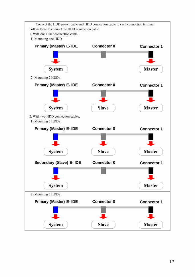
� Connect the HDD power cable and HDD connection cable to each connection terminal. Follow these to connect the HDD connection cable. 1. With one HDD connection cable, 1) Mounting one HDD
System Master
Primary (Master) E- IDE Connector 0 Connector 1
2) Mounting 2 HDDs
System MasterSlave
Primary (Master) E- IDE Connector 0 Connector 1
2. With two HDD connection cables, 1) Mounting 3 HDDs
System MasterSlave
Primary (Master) E- IDE Connector 0 Connector 1
System Master
Secondary (Slave) E- IDE Connector 0 Connector 1
2) Mounting 3 HDDs
System MasterSlave
Primary (Master) E- IDE Connector 0 Connector 1

18
System MasterSlave
Secondary (Slave) E- IDE Connector 0 Connector 1
� Mount the HDD bay again and secure it by screwing it back in place.
� Put the cover back on the upper case of the product and screw it back in place.
� Switch on the power and start the system.
After adding HDDs, follow a proper action from the {Main setup} → {Storage device} → {Local} → {3.Managing local storage device}. For more information, refer to the {Chapter 5. System setup} → {5-1 Main setup} → {5-1-5 Storage device}

19
Chapter� Operation and Setup tools The Premier 480/240 allows you to operate the system in a convenient way using front touch pad, remote control and mouse.
�-�Front-side Touch Pad
No. Name Function
1 POWER System power On/Off 2 LOG View system logs 3 RECORD Start/stop all channel recordings 4 SEARCH Search recorded images 5 STATUS View the system information/change the screen
settings 6 ESC Exit the current menu/Move to the upper menu 7 NUMBER Input of numbers, ranging 0 to 9(odd numbers:
press shortly, even numbers: press long) 8 Reverse Play / Fast Reverse Reverse play/ Fast reverse 9 Reverse Frame by Frame or TAB Reverse play by frame 10 Forward Frame by Frame or TAB Forward play by frame 11 Forward Play / Fast Forward Forward play/ Fast forward 12 SELECT Select item or change the screen sequentially 13 MOVE & DISPLAY Move the focus among items or change the display
mode 14 REMOTE The red light is turned on when the signal is
received from the remote control 15 NETWORK The blue light is turned on when a connection is
made remotely 16 BACKUP For backup, the orange light is turned on 17 HDD With a HDD is in operation, the red light is turned
on
Since the touch pad provides controls only for basic functions, it is recommended to use a mouse or the remote control.
20
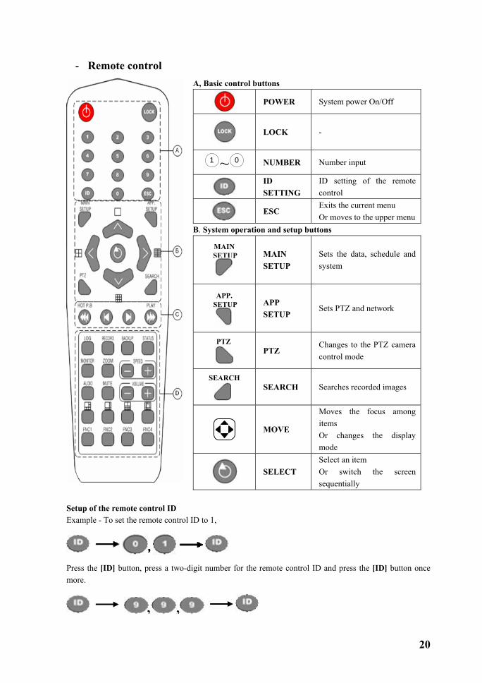
�-�Remote control
A, Basic control buttons
POWER System power On/Off
LOCK -
1 ~ 0 NUMBER Number input
ID SETTING
ID setting of the remote control
ESC
Exits the current menu Or moves to the upper menu
B. System operation and setup buttons
MAIN SETUP
MAIN SETUP
Sets the data, schedule and system
APP. SETUP
APP SETUP
Sets PTZ and network
PTZ
PTZ
Changes to the PTZ camera control mode
SEARCH
SEARCH Searches recorded images
MOVE
Moves the focus among items Or changes the display mode
SELECT
Select an item Or switch the screen sequentially
Setup of the remote control ID Example - To set the remote control ID to 1,
Press the [ID] button, press a two-digit number for the remote control ID and press the [ID] button once more.
, ,
21
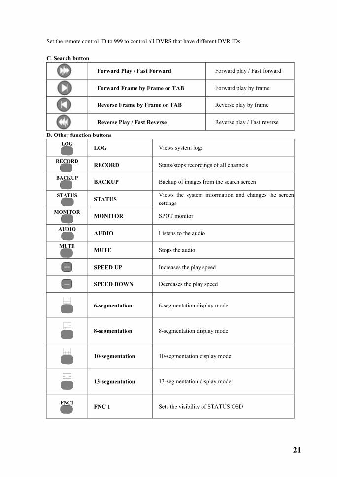
Set the remote control ID to 999 to control all DVRS that have different DVR IDs. C. Search button
Forward Play / Fast Forward Forward play / Fast forward
Forward Frame by Frame or TAB Forward play by frame
Reverse Frame by Frame or TAB Reverse play by frame
Reverse Play / Fast Reverse Reverse play / Fast reverse
D. Other function buttons LOG
LOG Views system logs
RECORD
RECORD Starts/stops recordings of all channels
BACKUP
BACKUP Backup of images from the search screen
STATUS
STATUS
Views the system information and changes the screen settings
MONITOR
MONITOR SPOT monitor
AUDIO
AUDIO Listens to the audio
MUTE
MUTE Stops the audio
SPEED UP Increases the play speed
SPEED DOWN Decreases the play speed
6-segmentation 6-segmentation display mode
8-segmentation 8-segmentation display mode
10-segmentation 10-segmentation display mode
13-segmentation 13-segmentation display mode
FNC1
FNC 1 Sets the visibility of STATUS OSD

22
�-�Mouse You can operate the system using aa USB mouse.
Right-clicking with the USB mouse enables the POPUP OSD (On Screen Display) menu to appear, as shown in the following figure. Right clicking with the mouse once more enables the POPUP OSD (On Screen Display) menu to disappear. Left-click with a USB mouse to run each context menu of the POPUP OSD menu. In the context menu, right-click with the mouse to exit the current menu.
No. Name Function 1 Lock Locks the usability of mouse, remote control and touch
screen 2 Main setup Sets the data, record schedule and system 3 App. setup Sets the PTZ and network 4 PTZ Changes the PTZ camera control mode 5 Search Searches the recorded images 6 Log Views the list of system logs 7 Record Starts/stops to record all channels 8 Status Views the system information and changes the screen
settings 9 Monitor SPOT monitor 10 Audio Listens to the audio 11 F1 Sets the visibility of STATUS OSD 12 F2 - 13 F3 - 14 F4 -
23
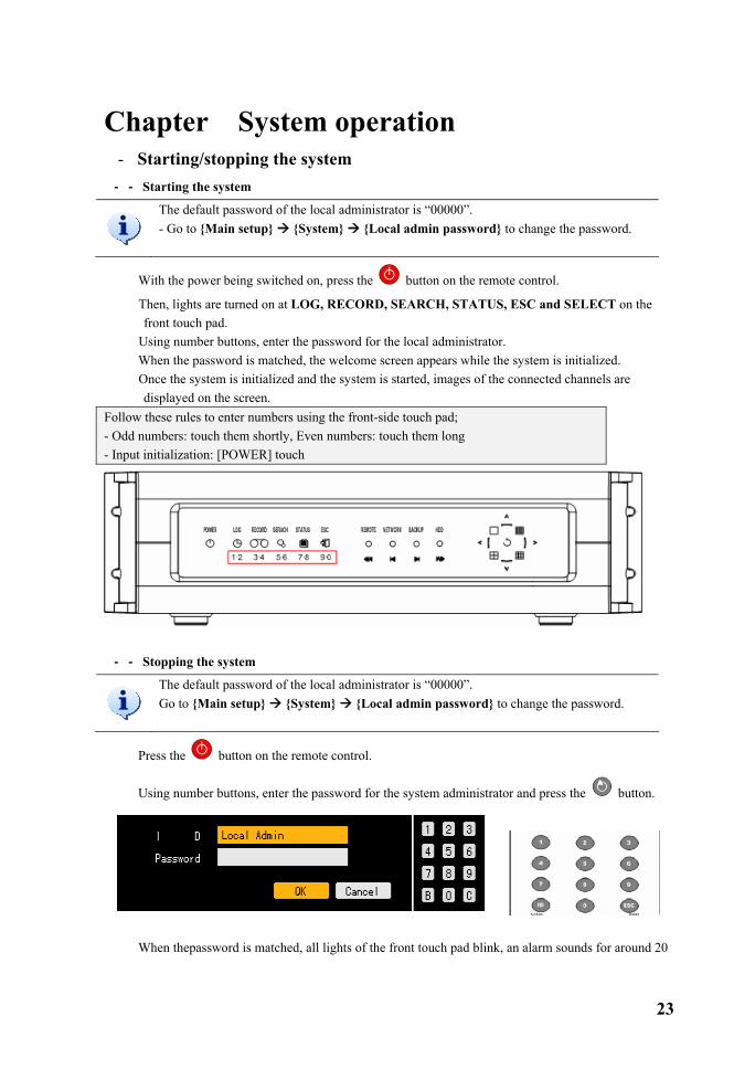
Chapter� System operation �-�Starting/stopping the system ��-���-���Starting the system
The default password of the local administrator is “00000”. - Go to {Main setup} {System} {Local admin password} to change the password.
� With the power being switched on, press the button on the remote control.
� Then, lights are turned on at LOG, RECORD, SEARCH, STATUS, ESC and SELECT on the front touch pad.
� Using number buttons, enter the password for the local administrator. � When the password is matched, the welcome screen appears while the system is initialized. � Once the system is initialized and the system is started, images of the connected channels are
displayed on the screen. Follow these rules to enter numbers using the front-side touch pad; - Odd numbers: touch them shortly, Even numbers: touch them long - Input initialization: [POWER] touch
��-���-���Stopping the system
The default password of the local administrator is “00000”. Go to {Main setup} {System} {Local admin password} to change the password.
� Press the button on the remote control.
� Using number buttons, enter the password for the system administrator and press the button.
� When thepassword is matched, all lights of the front touch pad blink, an alarm sounds for around 20

24
seconds and the system will shut down. � When the password is wrong, the warning message as in the following figure is displayed and it goes
back to the previous screen.
Follow these rules to enter numbers using the front touch pad; - Odd numbers: touch them shortly, Even numbers: touch them long - Input initialization: [POWER] touch

25
�-�System login ��-���-��� User account
Users that operate the system are classified into local system administrators who can use all functions by default and normal users.
Local Admin As a default account. Its default password is assigned to “00000”. This account has the right to use all functions including system setup, system power On/Off, system monitoring and recording screen viewing. - However, you can not access the system at a distance with this account.
User This account can be created for up to 4 people. There is a restriction on the use of system functions depending on the privileges assigned.
System function to set for users
Network Live Views the real-time screen through the network access Network play Views the recording screen through the network access Download network file Network access and file download Main setup App. setup
Data setup, record schedule, system, storage device, NTP, advanced setup PTZ camera, network setup
Network PTZ Control Controls the PTZ camera through the network access Network backup Backup function through the network access Remote upgrade Remote upgrade
��-���-���Login
For the system security, log on to the system to use the following functions.
Power
System power On/Off - Possible only as the local administrator
Lock/Unlock
Locks/unlocks the system - Possible only as the local administrator
MAIN SETUP
Main setup Data setup, recording schedule, system, storage device, NTP, advanced setup
APP. SETUP
App. setup Sets the PTZ settings and network settings
RECORD
Record Starts/stops the recordings for all channels

26
� If you press POWER, LOCK, MAIN SETUP, APP. SETUP or RECORD button, this screen that
prompts you to enter ID and password is displayed.
� Select a login account and enter the password for it using number buttons on the remote control.
• •
The initial password of the local administrator is “00000”. You can log on to the system as another registered user by moving the focus to the ID selection box and either pressing the direction ( ) button on the remote control or double-clicking it with the mouse left button.
� It the password is incorrect, this warning message is displayed.
27
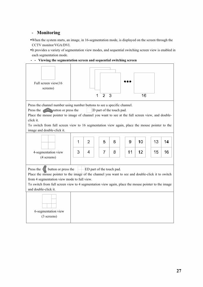
�-�Monitoring When the system starts, an image, in 16-segmentation mode, is displayed on the screen through the CCTV monitor/VGA/DVI. It provides a variety of segmentation view modes, and sequential switching screen view is enabled in each segmentation mode.
��-���-���Viewing the segmentation screen and sequential switching screen
Full screen view(16
screens)
Press the channel number using number buttons to see a specific channel. Press the button or press the LED part of the touch pad. Place the mouse pointer to image of channel you want to see at the full screen view, and double-click it. To switch from full screen view to 16 segmentation view again, place the mouse pointer to the image and double-click it.
4-segmentation view
(4 screens)
Press the button or press the LED part of the touch pad. Place the mouse pointer to the image of the channel you want to see and double-click it to switch from 4 segmentation view mode to full view. To switch from full screen view to 4 segmentation view again, place the mouse pointer to the image and double-click it.
6-segmentation view
(3 screens)

28
Press the button on the remote control. Using number buttons, you can switch the main channel view. To switch from 6 segmentation view mode to the main channel view mode, place the mouse pointer to the image of channel rather than main channel you want to see and double-click it.
8-segmentation view
(2 screens)
Press the button on the remote control. Using number buttons, you can switch the main channel view. To switch from 8 segmentation view mode to the main channel view mode, place the mouse pointer to the image of channel rather than main channel you want to see and double click it.
9-segmentation view
(2 screens)
Press the button or press the LED part of the touch pad. Place the mouse pointer to the image of the channel you want to see and double-click it to switch from 9 segmentation view mode to full view. To switch from full screen view to 9 segmentation view again, place the mouse pointer to the image and double-click it.
10-segmentation view
(2 screens) 0 5
1 2
3 4
7 8
5 6
9 10
Press the button on the remote control. Using number buttons, you can switch the main channel view. To switch from 10 segmentation view mode to the main channel view mode, place the mouse pointer to the image of channel you want to see rather than the main channel and double click it.

29
13-segmentation view
(2 screens)
Press the button on the remote control. Using number buttons, you can switch the main channel view. To switch from 10 segmentation view mode to the main channel view mode, place the mouse pointer to the image of the channel you want to see rather than the main channel and double click it.
16-segmentation view
(1 screens)
1 2 3 45 6 7 89 101112
13141516
Press the button or press the LED part of the touch pad. Place the mouse pointer to the image of the channel you want to see on the full screen view, and
double-click it. To switch from full screen view to 16 segmentation view again, place the mouse pointer to the image and double-click it.
Sequenctial screen view
At various live segmentation views of 1/4/6/8/9/10/13/16, press the button on the remote control. To stop the sequential screen view, press the button on the remote control once more. Then it switches the screen automatically and sequentially to show the image from the current segmentation mode.
- You can set the screen switch time interval from 1 to 5 seconds by pressing the button on the remote control. - Click the rotation button with the mouse to increase the time interval. To exit the rotation mode, select the 16-channel screen view mode.

30
�-�Recording/Playing Audio This function is provided when 4, 8 or 16-ch audio board is equipped. - For the audio setting, set the proper audio board type in the {Main setup} {System} as follows.
��-���-���Audio Recording setup
� On the real-time monitoring screen, press the MAIN SETUP button on the remote control. � Then, this login screen prompts you.
� Select the account you want to log in, enter the password using number buttons on the remote control
and select [Ok]. • (The initial password of the local administrator is “00000”.) You can log on to the system as another registered user by moving the focus to the ID selection box and either pressing the direction ( ) button on the remote control or double-clicking it with the mouse left button.

31
� When the password is matched, this {Main setup} initial screen is displayed.
� Using the direction buttons ( ), move to the channel you want to set in the {Main setup}
{Data1~4} {Record} {Audio} menu and press the [SELECT] button. � When the channel selection box is displayed, select the audio channel and save the task.

32
��-���-���Audio Live
� On the real time monitoring screen, press the AUDIO button on the remote control or mouse menu.
� An activation window appears along with the audio icon at the channel where the audio of the real time monitoring screen is set.
� Move the activation window using the direction buttons ( ) and press the [SELECT] button
to select the audio channel. � Then, it switched to the real time monitoring screen and the audio for the selected channel sounds.
33
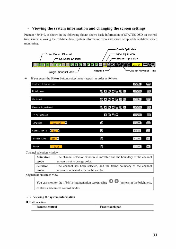
�-�Viewing the system information and changing the screen settings Premier 480/240, as shown in the following figure, shows basic information of STATUS OSD on the real time screen, allowing the real-time detail system information view and screen setup while real-time screen monitoring.
If you press the Status button, setup menus appear in order as follows.
Channel selection window
Activation mode
The channel selection window is movable and the boundary of the channel screen is set to orange color.
Selection mode
The channel has been selected, and the frame boundary of the channel screen is indicated with the blue color.
Segmentation screen view
You can monitor the 1/4/9/16-segmentation screen using buttons in the brightness,
contrast and camera control modes. ��-���-���Viewing the system information
Button action Remote control Front touch pad

34
� To go to the product information mode, press the Status button in the mouse menu.
1. ID Unique product ID (1~99, 255)
(It allows you to control products by ID remotely) 2. Name Product identification name 3. Software version Software version (Build number) 4. Hardware version Hardware version (Device type) 5. Front firmware version Front-side Touch Pad Firmware version 6. Video mode Video type (NTSC/PAL) 7.HDD information HDD
Total space Total space Used space Used space Free space Free space Start date Record start date End date Record end date
8. Network setup Network setup status IP address IP address
9. Overwriting Overwriting On/Off 10. DDNS server OFF or ON
35
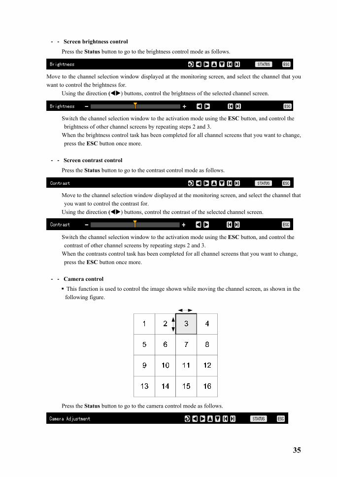
��-���-���Screen brightness control
� Press the Status button to go to the brightness control mode as follows.
Move to the channel selection window displayed at the monitoring screen, and select the channel that you want to control the brightness for.
� Using the direction ( ) buttons, control the brightness of the selected channel screen.
� Switch the channel selection window to the activation mode using the ESC button, and control the
brightness of other channel screens by repeating steps 2 and 3. � When the brightness control task has been completed for all channel screens that you want to change,
press the ESC button once more. ��-���-���Screen contrast control
� Press the Status button to go to the contrast control mode as follows.
� Move to the channel selection window displayed at the monitoring screen, and select the channel that
you want to control the contrast for. � Using the direction ( ) buttons, control the contrast of the selected channel screen.
� Switch the channel selection window to the activation mode using the ESC button, and control the
contrast of other channel screens by repeating steps 2 and 3. � When the contrasts control task has been completed for all channel screens that you want to change,
press the ESC button once more. ��-���-���Camera control
This function is used to control the image shown while moving the channel screen, as shown in the following figure.
� Press the Status button to go to the camera control mode as follows.
36
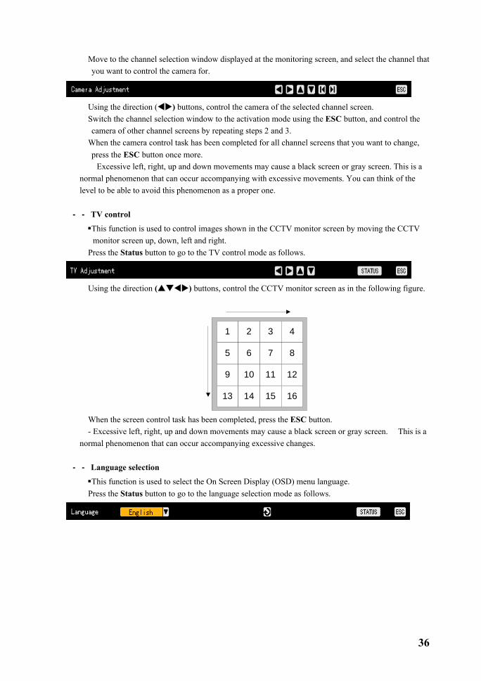
� Move to the channel selection window displayed at the monitoring screen, and select the channel that you want to control the camera for.
� Using the direction ( ) buttons, control the camera of the selected channel screen. � Switch the channel selection window to the activation mode using the ESC button, and control the
camera of other channel screens by repeating steps 2 and 3. � When the camera control task has been completed for all channel screens that you want to change,
press the ESC button once more. � Excessive left, right, up and down movements may cause a black screen or gray screen. This is a
normal phenomenon that can occur accompanying with excessive movements. You can think of the level to be able to avoid this phenomenon as a proper one.
��-���-���TV control
This function is used to control images shown in the CCTV monitor screen by moving the CCTV monitor screen up, down, left and right.
� Press the Status button to go to the TV control mode as follows.
� Using the direction ( ) buttons, control the CCTV monitor screen as in the following figure.
1 2
5 6
3 4
7 8
9 10
13 14
11 12
15 16
� When the screen control task has been completed, press the ESC button. - Excessive left, right, up and down movements may cause a black screen or gray screen. This is a
normal phenomenon that can occur accompanying excessive changes. ��-���-���Language selection
This function is used to select the On Screen Display (OSD) menu language. � Press the Status button to go to the language selection mode as follows.
37
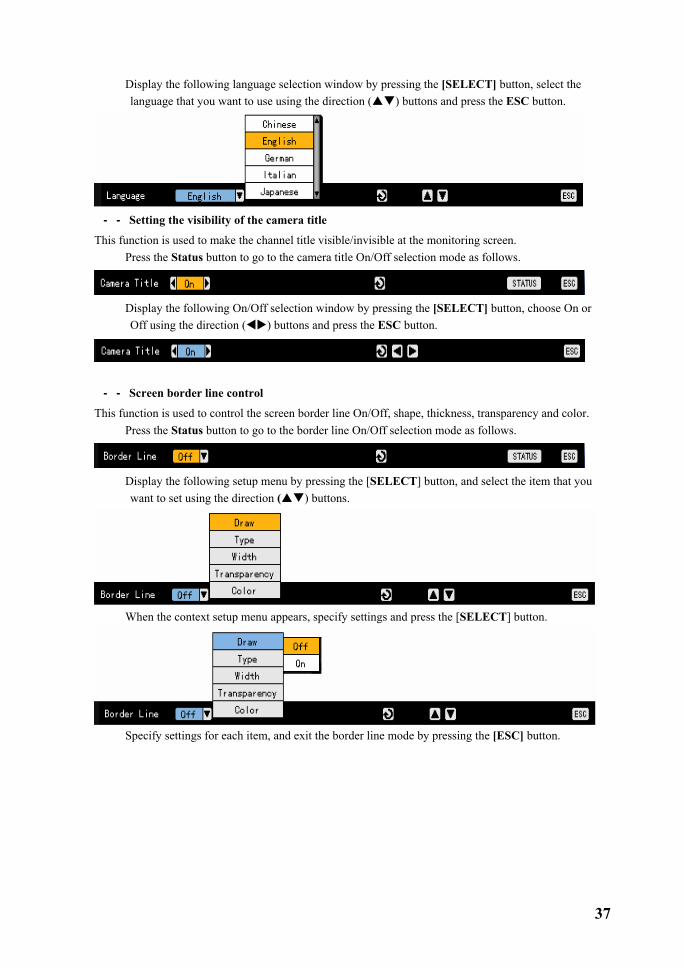
� Display the following language selection window by pressing the [SELECT] button, select the language that you want to use using the direction ( ) buttons and press the ESC button.
��-���-���Setting the visibility of the camera title
This function is used to make the channel title visible/invisible at the monitoring screen. � Press the Status button to go to the camera title On/Off selection mode as follows.
� Display the following On/Off selection window by pressing the [SELECT] button, choose On or
Off using the direction ( ) buttons and press the ESC button.
��-���-���Screen border line control
This function is used to control the screen border line On/Off, shape, thickness, transparency and color. � Press the Status button to go to the border line On/Off selection mode as follows.
� Display the following setup menu by pressing the [SELECT] button, and select the item that you
want to set using the direction ( ) buttons.
� When the context setup menu appears, specify settings and press the [SELECT] button.
� Specify settings for each item, and exit the border line mode by pressing the [ESC] button.
38
Border line setup items Name Setting Description
On Makes the border line of each channel screen visible.
Mode setup Off Makes the border line of each channel screen
invisible. Inner side Makes the frame boundary invisible.
Shape All Shows all border lines
Thickness 2 pixels, 4 pixels Sets the thickness of the border line. Transparency 10%, 25%, 50%, 75%, 100% Sets the transparency of the border line. Color Black, white, red, green, blue Sets the color of the border line.
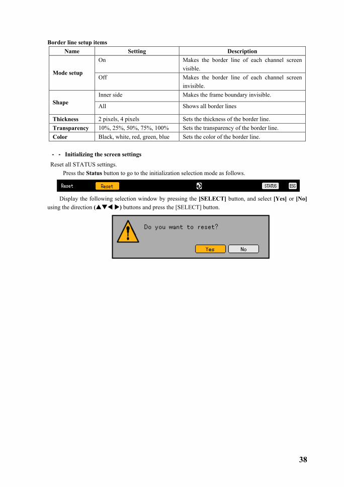
��-���-���Initializing the screen settings
Reset all STATUS settings. � Press the Status button to go to the initialization selection mode as follows.
Display the following selection window by pressing the [SELECT] button, and select [Yes] or [No]
using the direction ( ) buttons and press the [SELECT] button.
39
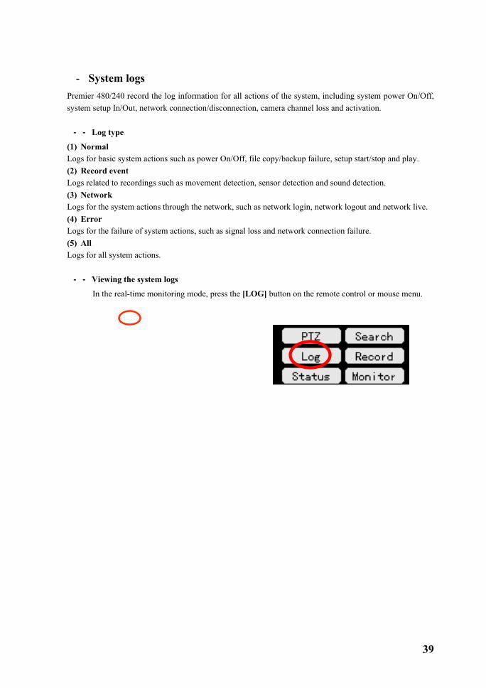
�-�System logs Premier 480/240 record the log information for all actions of the system, including system power On/Off, system setup In/Out, network connection/disconnection, camera channel loss and activation. ��-���-���Log type
(1) Normal Logs for basic system actions such as power On/Off, file copy/backup failure, setup start/stop and play. (2) Record event Logs related to recordings such as movement detection, sensor detection and sound detection. (3) Network Logs for the system actions through the network, such as network login, network logout and network live. (4) Error Logs for the failure of system actions, such as signal loss and network connection failure. (5) All Logs for all system actions. ��-���-���Viewing the system logs
� In the real-time monitoring mode, press the [LOG] button on the remote control or mouse menu.

40
� Then, this initial log list menu is displayed.
� At the activated calendar window as in the following figure, select year/month/day using the direction ( ) buttons and press the [SELECT] button.
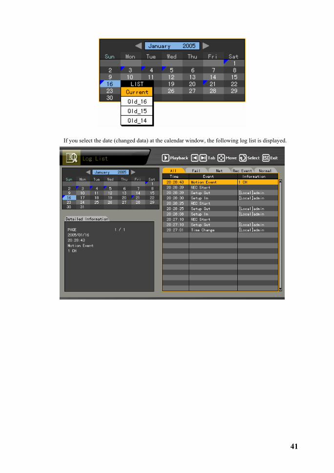
Viewing the log data related to the time change A stored data folder is newly created each time the user changes the time. At the calendar window, a blue triangle symbol marked on a date means that there is data and the time was changed, and a red triangle symbol means that there is only current data. To see details on the log information, select the date marked with the red triangle. If you select the date marked with the blue triangle, the changed data is listed as in the following figure.
41
� If you select the date (changed data) at the calendar window, the following log list is displayed.

42
� Move the focus using the direction ( ) buttons to see logs by time and type. � Using the [TAB] button to see logs by time and type for each page. � To play the record screen for a specific time, move the focus to the specified log and press the
[Play] button.
� When the record screen appears, press the [Play] button.
A record image is played by second, Example - If you try to play the image with the log stored at 19:45:16, image frames recorded since 19:45:16 are played.
� Press the [ESC] button to return to the previous log list.
43
�-�Recording ��-���-���Recording type
Premier 480/240 support various recording types as in the following table. Record type Description Auto With having event record frames and normal record frames distinguished,
records images by selecting the record type automatically depending on each setting. The event record frame is used when a movement, sensor or sound is detected, and the normal frame is used otherwise.
Continuous Records images always depending on the value of normal frame. Motion When there is a movement, records images depending on the value of the event
frame. Sensor When an input signal is received from an external sensor, records images
depending on the value of event frame. Sound When a sound is detected, records images depending on the value of event
frame. ��-���-��� Recording setup
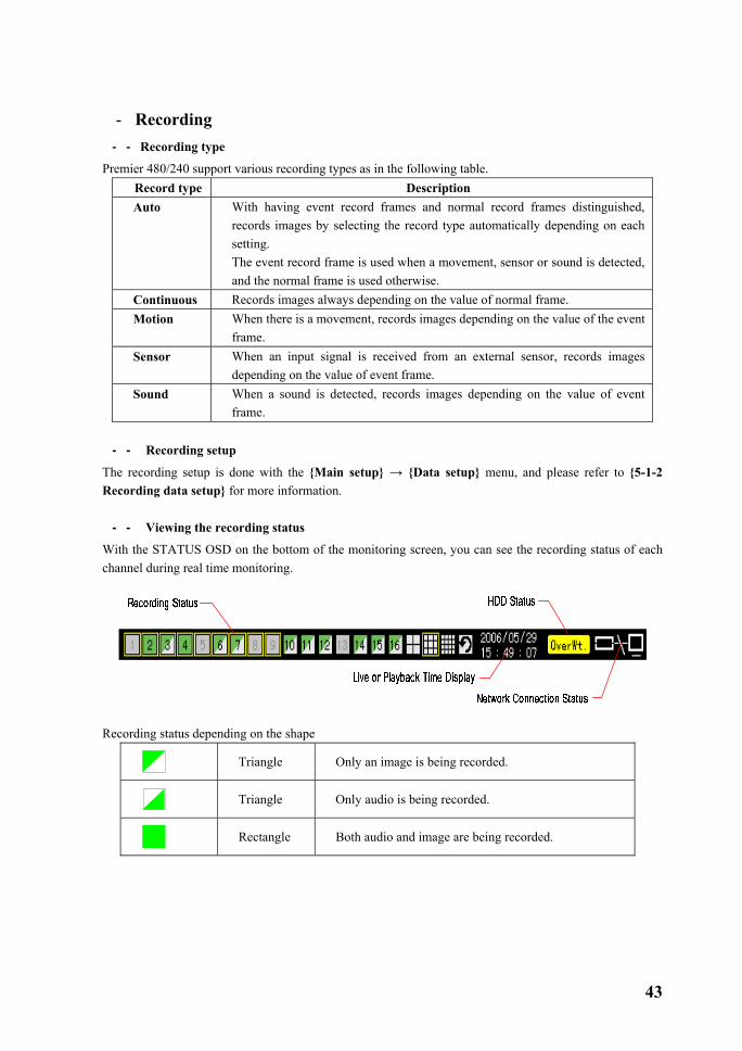
The recording setup is done with the {Main setup} → {Data setup} menu, and please refer to {5-1-2 Recording data setup} for more information. ��-���-��� Viewing the recording status
With the STATUS OSD on the bottom of the monitoring screen, you can see the recording status of each channel during real time monitoring.
Recording status depending on the shape
Triangle Only an image is being recorded.
Triangle Only audio is being recorded.
Rectangle Both audio and image are being recorded.

44
Recording status depending on the color
Green Continuous recording
Red Motion recording
Blue Sensor recording
Yellow Sound recording
No color No recording
HDD status Check the right side of the STATUS OSD to see the status of HDD that recorded images are stored in, as in the following figure. - HDD overwriting On/Off setup is done with the {Main setup} → {Storage device} menu.
When the HDD overwriting function is enabled.
When the HDD overwriting function is disabled.
Network access status Check the right side of the STATUS OSD to see the status of the network connection, as in the following figure.
Network is connected Network is not connected
��-���-���Starting/stopping all recordings
To start or stop all channel recordings, either touch the [RECORD] button on the front touch pad or press the [RECORD] button on the remote control/mouse menu.

45
(1) Stopping all recordings � Touch the [RECORD] button on the front touch pad or press the [RECORD] button on the remote
control/mouse menu. � When the following login window prompts you, enter ID and password and select [Ok].
� Recording at all channels is stopped, and STATUS OSD indicates that all channel recordings are stopped as in the following figure.
(2) Starting all recordings
� While all channel recordings are stopped, touch the [RECORD] button on the front touch pad or press the [RECORD] button on the remote control/mouse menu.
� When the following login window prompts you, enter the ID and password and select [Ok].
� All channel record is started depending on the record settings, and the STATUS OSD part indicates that all channel record is running, as in the following figure.
��-���-���Watermark
This product provides the watermark to detect any illegal modification of images. In particular, the fragile watermark technology, is used. A mark, given with the fragile watermark technology, inserted into the image is easily damaged When then image is illegally modified, indicating the information such as position and format of the illegal modification. In general, it is designed for the purpose of the authentication and integrity of the images recorded on this product. In this product, the watermark is inserted into all images and the damage status of each watermark can be detected with our watermark detector.

46
�-�Search The search function is used to play the recorded images by searching them by year/month/day/hour/minute. ��-���-���Going to the search mode
� If you touch the SEARCH button of the front touch pad or press the SEARCH button on the remote control/mouse button in the real-time monitoring mode, the following search mode initial menu is displayed.
Activation mode and selection mode
Activation mode
Allows you to move/select an item on the OSD menu, and the frame boundary or focus is indicated with the yellow color.
Selection mode
This mode means that an item on the OSD menu has been selected, and the frame boundary or selection box is indicated with the blue color at this mode.

47
��-���-���Selecting a search method
� Before selecting the date, move the focus to the search method selection window by pressing the
button and select the search method using the direction ( ) buttons.
Multi-channel Searches several channels at the same time range. Multi-day Searches one channel by date at the same time range. Multi-hour Searches one channel several times by hour for the same day.
��-���-���Selecting a search tool
� Before selecting the date, move the focus to the search tool selection window by pressing the button and select the search tool using the direction ( ) buttons.
(2) Search using the histograms
� If you select the search date, the recorded images are shown as histograms as in the following figure. Green Indicates continuous recording Red Indicates motion recording. Blue Indicates sensor recording. Yellow Indicates sound recording.
Skyblue Indicates that a recording has been done before the time was changed.
B) Multi-channel type Specify the time by pressing direction ( ) buttons.

48
C) Multi-hour type Specify the start time and channel by pressing direction ( ) buttons.
D) Multi-day type Specify the time and channel by pressing direction ( ) buttons.

49
(3) Search using the file list � If you select the search date, the recorded images are displayed as a file list as below. � Select the recorded time zone by moving the focus using the direction ( ) buttons.
� Viewing the file list data related to the time change
1) A data folder is newly created whenever the time is changed at the {Main setup} → {NTP} → {2. Date and time}, and the changed folder is searched from the file list in blue.
2) If you select the changed time, the list that allows you to select the changed folder is displayed as in the following figure.
- It works only with multi-channel.
50
Current Recording image file based on the current time of the system Old_NUM Recording image file before the system time was changed
��-���-���Multi-channel
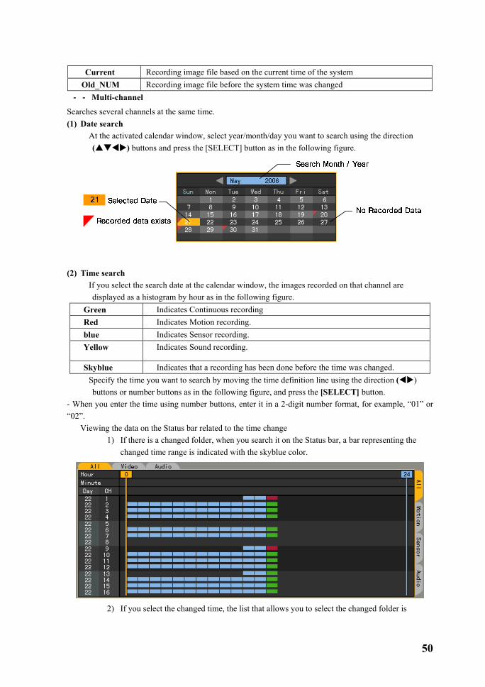
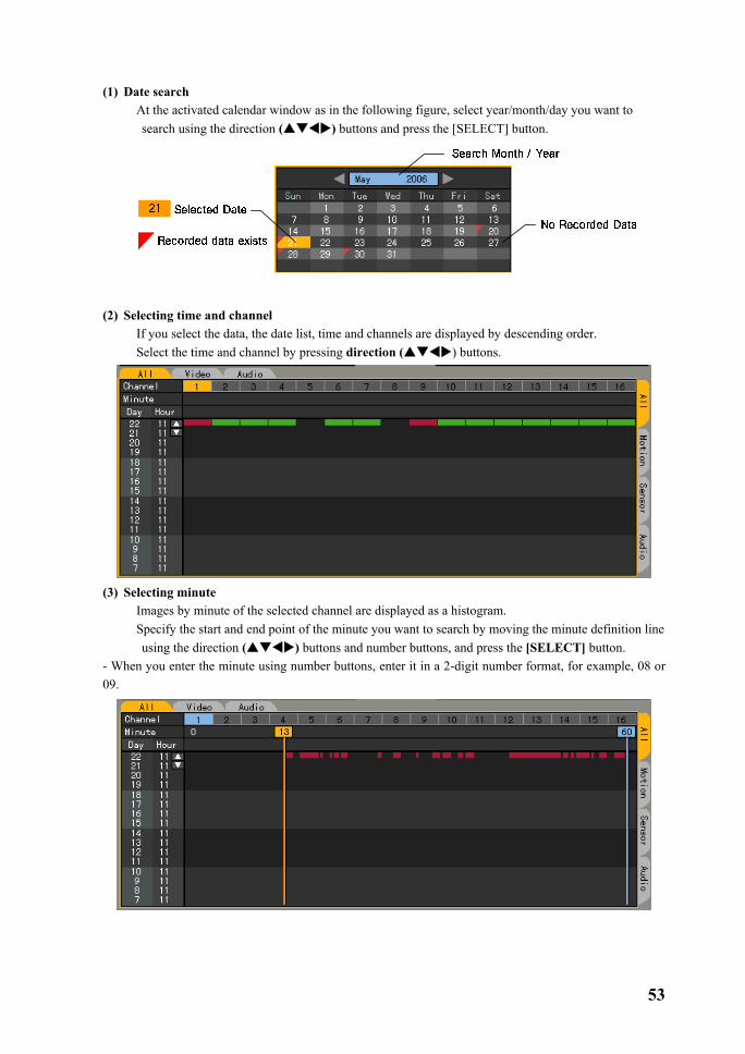
Searches several channels at the same time. (1) Date search
� At the activated calendar window, select year/month/day you want to search using the direction ( ) buttons and press the [SELECT] button as in the following figure.
(2) Time search
� If you select the search date at the calendar window, the images recorded on that channel are displayed as a histogram by hour as in the following figure.
Green Indicates Continuous recording Red Indicates Motion recording. blue Indicates Sensor recording. Yellow Indicates Sound recording.
Skyblue Indicates that a recording has been done before the time was changed. � Specify the time you want to search by moving the time definition line using the direction ( )
buttons or number buttons as in the following figure, and press the [SELECT] button. - When you enter the time using number buttons, enter it in a 2-digit number format, for example, “01” or “02”.
Viewing the data on the Status bar related to the time change 1) If there is a changed folder, when you search it on the Status bar, a bar representing the
changed time range is indicated with the skyblue color.
2) If you select the changed time, the list that allows you to select the changed folder is

51
displayed as in the following figure. - It works only with multi-channel.
(3) Selecting minute
� If you select the hour, images recorded at each channel are displayed as a bar graph by minute. � Specify the start and end point of the minute you want to search by moving the minute definition line
using the direction ( ) buttons and number buttons, and press the [SELECT] button. -When you enter the minute using number buttons, enter it in a 2-digit number format, for example, “08” or “09”.
��-���-���Multi-hour
Searches one channel several times by hour for the same day. (1) Date search
� At the activated calendar window as in the following figure, select year/month/day you want to search using the direction ( ) buttons and press the [SELECT] button.

52
(2) Selecting start data and channel � If you select the date, the time of the selected date and channel is displayed as in the following figure. � Select the start time and channel by pressing direction ( ) buttons.
(3) Selecting minute
� Images by time of the selected channel are displayed as a histogram. � Specify the start and end point of the minute you want to search by moving the minute definition line
using the direction ( ) buttons and number buttons, and press the [SELECT] button. �When you enter the minute using number buttons, enter it in a 2-digit number format, for example, 08 or 09.
��-���-���Multi-day
Searches one channel by date at the same time range.
53
(1) Date search � At the activated calendar window as in the following figure, select year/month/day you want to
search using the direction ( ) buttons and press the [SELECT] button.
(2) Selecting time and channel � If you select the data, the date list, time and channels are displayed by descending order. � Select the time and channel by pressing direction ( ) buttons.
(3) Selecting minute
� Images by minute of the selected channel are displayed as a histogram. � Specify the start and end point of the minute you want to search by moving the minute definition line
using the direction ( ) buttons and number buttons, and press the [SELECT] button. - When you enter the minute using number buttons, enter it in a 2-digit number format, for example, 08 or 09.

54
�-�Playback ��-���-���Going to the playback mode
You can go to the mode using the [PLAY] button on the remote control/mouse menu in {Search}, {Log} and {Real-time monitoring} modes. In the case of log and real-time monitoring modes multi-channel modes, play can be done only with the multi-channel mode. However, the play through a search task can be done with multi-channel/multi-day/multi-hour modes.
(1) Search
� Select Multi-channel/Multi-Day/Multi-hour in the {Search} mode. � Set date, hour or channel, and minute to play in the {Search} mode, and select either the [PLAY]
button on the remote control or [PLAYBACK] button located in the upper-middle side of the {Search} mode
� The play screen for multi-channel/multi-day/multi-hour is as follows.
1) Multi-Channel
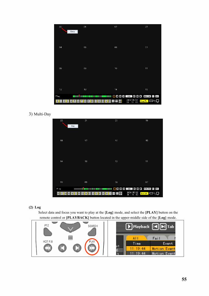
2) Multi-Hour
55
3) Multi-Day
Day
(2) Log
� Select data and focus you want to play at the {Log} mode, and select the [PLAY] button on the remote control or [PLAYBACK] button located in the upper-middle side of the {Log} mode.

56
� The playback initial screen for multi-channel is displayed.
(3) Playback(Hot P.B) � At the real-time monitoring screen, press the [PLAY] button on the remote control or mouse menu.
� When the following figure is displayed, select the time and date when you want to play using the direction ( ◄►) buttons and press the [SELECT] button.
� If you select the [Ok] button and press the [SELECT] button, the initial play screen for the multi-
channel mode is displayed. - The data stored before the time is changed can not be played.
��-���-���Playback and playback speed control
(1) Playback � To play images, press the following search button in the play mode.
- Description on search buttons

57
Button Name Function
Forward Frame by Frame Forward play by frame Pause during image play
Forward Play / Fast Forward Forward play(X1) / Fast forward(X30)
Reverse Frame by Frame Reverse play by frame Pause during image play
Reverse Play / Fast Reverse Reverse play(X1) / Fast Reverse(X30)
SPEED DOWN Increase the play speed
SPEED UP Decrease the play speed
(2) Playback speed control A) Increasing/decreasing the playback speed( by 1-x)
� If you, at the status of 1-x play, press the SPEED (+/-) button on the remote control, the image
play speed increases/decreases by 1-x. -With 1-x speed, you can play an image at a speed, ranging from (x 1/29) to (x 29).
B) Increasing/decreasing the playback speed( by 30 -x)
� If you, at the status of 30-x play, press the SPEED(+/-) button on the remote control, the image
play speed increases/decreases by 30-x. -With 30-x speed, you can play an image at a speed up to (x 300).
��-���-���Playback with segmentation screen
In the search mode, you can play an image with 1, 4, 9 or 16-segmentation screen.
Full screen view
(16 screens)
58
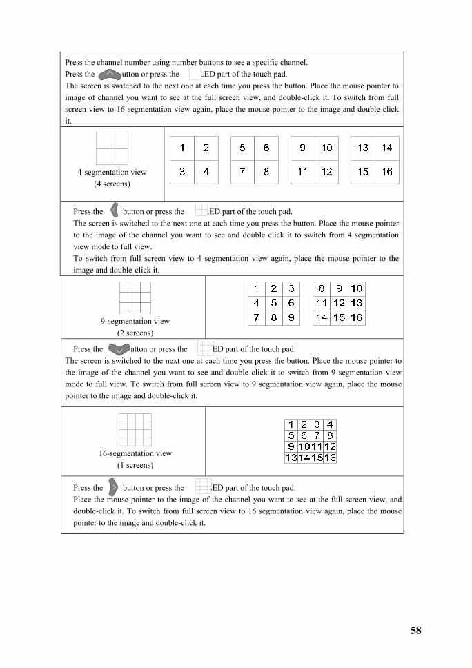
Press the channel number using number buttons to see a specific channel. Press the button or press the LED part of the touch pad. The screen is switched to the next one at each time you press the button. Place the mouse pointer to image of channel you want to see at the full screen view, and double-click it. To switch from full screen view to 16 segmentation view again, place the mouse pointer to the image and double-click it.
4-segmentation view
(4 screens)
Press the button or press the LED part of the touch pad. The screen is switched to the next one at each time you press the button. Place the mouse pointer to the image of the channel you want to see and double click it to switch from 4 segmentation view mode to full view. To switch from full screen view to 4 segmentation view again, place the mouse pointer to the image and double-click it.
9-segmentation view
(2 screens)
Press the button or press the LED part of the touch pad. The screen is switched to the next one at each time you press the button. Place the mouse pointer to the image of the channel you want to see and double click it to switch from 9 segmentation view mode to full view. To switch from full screen view to 9 segmentation view again, place the mouse pointer to the image and double-click it.
16-segmentation view
(1 screens)
Press the button or press the LED part of the touch pad. Place the mouse pointer to the image of the channel you want to see at the full screen view, and double-click it. To switch from full screen view to 16 segmentation view again, place the mouse pointer to the image and double-click it.

59
��-���-���Audio Playback
� In the play mode, press the AUDIO button on the remote control.
When using the mouse, a popup menu is displayed if you move the mouse to the right-upper side of the screen. Then, select the [AUDIO] button.

60
� The channel set to record audio, as in the following figure, is indicated by audio mark, and an orange-color activation window is created.
� Move the activation window using the direction ( ) buttons and press the [SELECT] button. � The recorded audio is played for the selected channel.
��-���-���Mute
The mute function turns the sound off for the selected channel. � Press the [MUTE] button in the playback mode.
When using the mouse, a popup menu is displayed if you move the mouse to the right-upper side of the screen. Then, select the [Mute] button. #1 channel includes the audio output icon.

61
� If you press the [Mute] button, audio output icon is changed as follows.
��-���-���Smart search
This function is used to search an image for object movement at a specific zone.

62
� Press the [SEARCH] button on the remote control in the play mode.
When using the mouse, a popup menu is displayed if you move the mouse to the right-upper side of the screen. Then, select the [Smart] button.

63
� Select the channel you want to search.
� When the zone setup screen is displayed, move to the zone you want to search by moving the green
focus using the direction ( ) buttons. If you press the [SELECT] button, the search zone setup is started. If you move the green focus using the direction ( ) buttons, the zone to be searched is indicated with the green color. To set the search zone, confirm the search zone and press the [SELECT] button.
Up to 4 search zones can be set.

64
To set the sensitivity of the movement, press the right mouse button in the green search zone or press the [MAIN SETUP] button on the remote control. The sensitivity of the movement can be set to 5 levels; lowest/low/middle/high/highest. The default value is middle.
� If you, after the zone setup is completed, press the [PLAYBACK] button or move the mouse pointer to the play control bar in the playback mode, the play control bar is displayed. Press the play button to start the smart search.
� When the smart search is completed, the following search screen is displayed.
� On the play status bar, the part in which a movement occurred in the search zone is indicated with the green color.
� Using the following search buttons, play images found with the smart search.
��-���-���Digital zoom
This function is used to enlarge a specific zone you want to see in details.

65
� Press the [ZOOM] button in the playback mode.
When using the mouse, a popup menu is displayed if you move the mouse to the upper right side of the screen. Then, select the [ZOOM] button.
� When the activation window is displayed, move to the channel where you want to enlarge images by
pressing direction ( ) buttons and press the [SELECT] button. � The full screen view for the selected channel is displayed and the screen is zoomed In/Out by the
order of X2, X3, X½ at each time you press the [ZOOM] button.
To move the focus position of the enlarged screen, use direction ( ) buttons. Click a point on the screen with the mouse and move it to the position you want to zoom.

66
��-���-���Simultaneous playback/real-time monitoring
The Premier 480/240 allows you to play recorded images and monitor real-time images at the same time. � Press the [MONITOR] button on the remote control in the playback mode.
� As shown in the following figure, VGA monitor and DVI monitor play recorded images, and TV
monitor displays real –time images.

67
�-��Backup The Premier 480/240 provides the USB 2.0 & IEEE1394 backup interfaces. For the backup task, a backup drive such as IEEE1394 should be mounted on the EXT0 or EXT1 on the back side of the system. Before doing backup, connect the external type HDD, external CD-RW or another storage device that supports the interface for the backup card to the EXT0 or EXT1 on the back side of the system. For more information on the external device support, please refer to Appendix.
� Go to {Search} – {Multi-channel} – {Minute} selection window as in the following figure. -For more information about how to search, please refer to 4-8. Search.
� Select either [BACKUP] button on the remote control or [BACKUP] button located in the upper-
middle side of the {Search} mode.

68
� When the connection device selection list is displayed, select the connection device of the connected storage device that you want to use.
� While checking the indication of the backup capacity, control the capacity to be stored using the direction (▲▼ ) buttons and press the [SELECT] button. Note ! To select or deselect a backup channel, move the focus to the channel using the
direction (▲▼) buttons and press the [SELECT] button. - The backup channel is indicated with the red square. To select the backup time, move the focus to the backup start minute bar using the button and change the position of the minute bar using ( ) buttons. If you press the [SELECT] button, the focus moves to the backup finish minute bar.

69
� To see the backup information, press the [BACKUP] button on the remote control or [BACKUP] button located in the upper-middle side of the {Search} mode. See the backup information, and select the [Yes] on the confirm message window.
When the backup storage device is not formatted or a part of the storage space is being used, the following message is displayed. Then, select the [Yes] to delete the existing data.
� The following message is displayed and the backup is started.

70
� When the following message is displayed after the backup is completed, press the [SELECT] button.
� When the following message prompts you, separate the backup device from EXT0 or EXT1 in the
rear side of the system.

71
�-��PTZ camera control ��-�����-���Prerequisites for PTZ function
� The PTZ camera should be linked to the system. � Settings for the PTZ camera should be completed properly in the {APP. Setup} → {PTZ Setup}.
-For more information on the setup of the PTZ cameras, please refer to the {APP. Setup} → {PTZ Setup}. ��-�����-���Going to PTZ mode
� In the real time monitoring mode, press the PTZ button on the remote control. � The channel where the PTZ camera is set, as in the following figure, is indicated with an icon, and
the channel selection window is displayed.
� If you have no PTZ camera set, the following message window is displayed.
Channel selection window
Activation mode
The channel selection window is movable and the frame boundary of the channel screen is set to orange color.
Selection mode
The channel has been selected, and the frame boundary of the channel screen is indicated with the blue color.
��-�����-���PTZ control
(1) Left-right/Up-down rotation � Select one of the channels where the PTZ camera is set to control the PTZ by moving the channel
selection window displayed on the monitoring screen in the {PTZ} mode. � Once a channel is selected, left-right/up-down rotation mode comes up as in the following figure.

72
� Control the amount of left-right/up-down using the direction ( ) buttons. � To see the segmentation screen in the left-right/up-down mode, press the left/right [TAB] button.
(2) Zoom In/Out � If you, in the left-right/up-down mode, press [PTZ] button on the remote control, it goes to the zoom
control mode as in the following figure.
Use direction (▲▼) buttons to zoom in (▼) /out(▲) an image.
� To see the segmentation screen in the zoom in/out mode, press the left/right [TAB] buttons. (3) Focus control
� If you, in the zoom in/out mode, press [PTZ] button on the remote control, it goes to the focus control mode as in the following figure.
� Use direction (▲▼) buttons to control the focus of the camera. � To see the segmentation screen in the focus control mode, press the left/right [TAB] buttons.
(4) Specifying preset The preset means a preference to store left-right/up-down/zoom/focus PTZ camera under various conditions.
� In the left-right/up-down, zoom or focus mode, press the [SELECT] button. � Move the number button in the status OSD menu under the monitoring screen to the number you
want to specify using the direction ( ) buttons as in the following figure, and press the [SELECT] button. The number range you can specify is 1 to 8.
� The specified number turns to the blue color as in the following figure, and the control screen is stored for the specified number.
(5) Using preset
� In the left-right/up-down, zoom or focus control mode, press one of 1 to 8 on the remote control. � It goes to the status corresponding to the number including left-right/up-down/zoom/focus settings of
the PTZ camera. (6) Using tour function The tour function is used to switch the preset screen by a specified order automatically. The preset means a preference to store left-right/up-down/zoom/focus PTZ camera under various conditions. For more information on the setup of the tour function, please refer to the {App. Setup} → {PTZ Setup} → {Tour}.
� The tour function, in the left-right/up-down, zoom or focus mode, is set, #9 or #0 of the STATUS OSD and is indicated with the blue color as in the following figure.

73
� In the left-right/up-down, zoom or focus control mode, press one of number buttons (9, 0) on the remote control.
� Depending on the setting tour order, the preset screen is automatically and sequentially switched. � To stop the tour function, press the number (9,0) of the tour that is working.
Tour1 Has been specified to #9. Tour2 Has been specified to #0.

74
�-��Manual SPOT This function is used to display the desired channel on the SPOT monitor.
� Press the [MONITOR] button as in the following figure.
� Then, the following figure is displayed at the right-upper side of the screen.
No mouse When moving the mouse
SPOT :
1 2 3
4 5 6
7 8 9
C 0 S
SPOT :
C – ESC S - SELECT
� If you select a channel using a number button on the remote control, The SPOT monitor setup
window disappears and the screen of the selected channel is displayed on the SPOT monitor.
Canceling the SPOT monitor When the setup window is displayed as above, you can cancel the SPOT monitor view as follows even When the SPOT monitor is not running.
1) Press the [ESC] button. 2) After 5 seconds since the window is displayed, it is cancelled. 3) After pressing 0, if you press the [SELECT] button or 5 seconds later, it is cancelled.

75
Chapter� System setup The system setup consists of {Main setup} and {APP. setup} as follows.
Main setup App. setup
Data setup PTZ setup Record schedule Network System Storage device NTP Advanced
�-�Main setup The {Main setup} is used to set recording, system environment and other major functions.
��-���-���Starting the main setup
� At the real-time monitoring screen, press the Main Setup button on the remote control.
� Then, this login screen prompts you.
� Select the account you want to log in, enter the password using number buttons on the remote control
and select [Ok]. • (The initial password of the local administrator is “00000”.) • If you press the direction ( ) buttons when the focus is on the ID selection box, another registered user ID is enabled.

76
� When the password is matched, this {Main setup} initial screen is displayed.
��-���-���Recording setup
This function is used to set recording and events (1) Selecting Recording setup menu mode There are two menu types, data mode and channel mode, in the {Recording setup}. A) Selecting the menu type
� Move the focus to the [Change] button on the bottom of data mode menu and channel mode menu using the [TAB] button and direction ( ) buttons on the remote control, and press the [SELECT] button.
Data mode menu
Channel mode menu

77
Data mode
Based on the data profile ranging from data 1 to data 4, this mode is used to set the data for each channel ranging from 1 to 16.
Channel mode
Based on 4-channel group, this mode is used to set the data for each channel ranging from 1 to 16 as in the following figure.

78
(2) Saving record settings When you have changed the settings of each menu at the {Recording setup}, save the settings you changed before exiting the menu. A) Saving settings to the current data
� Move the focus to the [Save] button using the [TAB] button and direction ( ) buttons on the remote control, and press the [SELECT] button.
B) Saving settings to other data Saves the current settings to several data selections ranging from data 1 to data 4.
� Move the focus to the [Save As] button using the [TAB] button and direction ( ) buttons on the remote control, and press the [SELECT] button.
� You can select more than one of data 1 ~data 4. The selected one is indicated with the green color,
and it is focused with the blue color when you leave it. C)Saving settings at the message window
� If you exit the record setting without saving the changed values, the following warning message window is displayed.
� Press the [Yes] to save the changed settings.
Yes Saves the current settings and, goes back to the main setup screen. No Goes back to the main setup screen without saving the current settings. Cancel Cancels the current task and goes back to the previous view.

79
(3) Channel name setup Sets the name and camera input for each channel.
� Using the direction ( ) buttons, move the focus to the channel you want to set in the {Data setup} {Data1~4} {Name} and press the [SELECT] button.
� When the selection box is displayed, place the focus on the {name} and press the [SELECT] button.
� When the title input box is displayed as in the following figure, enter a channel name using the direction ( ) buttons and press the [SELECT] button.
Caps Lock Switches between
upper/lower cases BS Deletes one letter
backward Space Inserts a blank
Cancel Cancels saving
Save & Exit Saves & Exits
� After you finished entering the channel name, move the focus to [Save& Exit] using the direction ( ) buttons or [TAB] button, and press the [SELECT] button to save the settings.
(4) Hiding the channel Disables the visibility of the channel image on the real-time monitoring screen.
� Using the direction ( ) buttons, move focus to the channel you want to set in the {Main setup} {Data1~4} {Name} menu and press the [SELECT] button.
� When the selection box is displayed, place the focus to the {Covert} and press the [SELECT] button.

80
Screen indication will depend on the Recording setup and camera image input. V.L It stands for Video Loss, indicating the camera image input is damaged or lost. V.D It stands for Video Disconnection, indicating that Record or Live is set to Off
although the camera image input exists. V.C It stands for Video Covert, indicating the recording status, but is not shown on
the Live screen. (5) Channel On/Off Sets the connection for the input images.
� Using the direction ( ) buttons, move focus to the channel you want to set in the {Main setup} {Data1~4} {Name} menu and press the [SELECT] button.
To set all channels with the same value at once, move the focus to the {Title} and press the [SELECT] button.

81
� When the selection box is displayed, place the focus to the {On} or [Off], and press the [SELECT] button.
On Connects the input image of the camera. Off Disconnects the input image of the camera.
(6) Recording Sets the recording resolution, recording quality, recording type, recording frame and sound recording On/Off. A) Recording resolution setup Sets the resolution of the channel you want to record.
� Using the direction ( ) buttons, move focus to the channel you want to set in the {Data setup} {Data1~4} {Name} {Record} {Res.} menu and press the [SELECT] button.
To set all channels with the same value at once, move the focus to the {Res.} and press the [SELECT] button.
� When the selection box is displayed, select the resolution using the direction ( ) buttons and the
[SELECT] button. Resolution based on video type
Type Resolution
NTSC PAL
CIF 352X240 352X288 Field 704X240 704X288 Full 704X480 704X576

82
B) Record image quality setup Sets the quality of the recording image.
� Using the direction ( ) buttons, move the focus to the channel you want to set in the {Data setup} {Data1~4} {Name}} {Record} {Qua.} menu and press the [SELECT] button.
To set all channels with the same value at once, move the focus to the {Qua.} and press the [SELECT] button.
� When the selection box is displayed, select the recording quality using the direction ( ) buttons
and press the [SELECT] button.
Note ! Size of the recording image files depends on the recording quality Recording quality Size of recording image file Lowest Low Middle High Highest

83
C) Record type setup Type Description Auto Having event record speed and normal record speed set differently, the system
records images by selecting the record type automatically depending on each setting. Continuous Records images all the time, based on normal setup. Motion When there is motion, it records images depending on the value of the event setup. Sensor When an input signal is received from an external sensor, it records images
depending on the value of the event setup. Sound When a sound is detected, it records images depending on the value of the event
frame.
Recording condition Type Description
Continuous {Record} {Rate} Normal: 1~30 Motion {Event} {Motion}: partial or overall Sensor {Event} {Sensor}: 1~16 Sound {Event} {Sound}:1~16
{Recording} {Rate} Event: 1~30
Auto Both Normal and Event are settable at the same time � Using the direction ( ) buttons, move to the channel you want to set in the {Recording
setup} {Data1~4} {Record} {Mode} menu and press the [SELECT] button.
To set all channels with the same value at one time, move the focus to the {Mode} and press the [SELECT] button.
� When the selection box is displayed, select the recording type using the direction ( ) buttons and
press the [SELECT] button.

84
D) Record frame setup Depending on the recording type, the record frame is divided into two types; Normal and Event.
Normal Sets the record frame rate for Auto and Continuous types. Event Sets the record frame rate for Auto, Motion, Sensor and Sound types.
Note ! Max. Record frame depending on the resolution
Resolution Model name
CIF (352X240) Field (704X240) Full (704X480)
Premier 480 480fps 240fps 120fps Premier 240 240fps 120fps 60fps The Premier 480/240 can handle images by grouping 4 channels as one. Therefore, it is possible to configure a variety of record settings depending on the record resolution and frame rate. Max. record frame of one group depending on the resolution
Resolution Model name
CIF (352X240) Field (704X240) Full (704X480)
Premier 480 120fps 60fps 30fps Premier 240 60fps 30fps 15fps
Example - Record setting of each group
Group1) 1~4 CH
Group 2) 5~8 CH
Group 3) 9~12 CH
Group 4) 13~16 CH

85
� Using the direction ( ) buttons, move the focus to the channel you want to set in the {Recording setup} {Data1~4} {Record} {Rate} menu and press the [SELECT] button.
� When the selection box is displayed, select the recording frame using the direction ( ) buttons and press the [SELECT] button.
To set all channels with the same value at once, move the focus to the {Rate} and press the [SELECT] button.
� When the setting frame rate is larger than the Max. record frame, the following menu is displayed.
� In the above figure, the channel indicated with the red color is the one you set just now. ‘N’ and ‘E’
stand for Normal and Event, respectively. If there is a channel that is not used, its rate is reduced first and then others are followed. When the channel mode is being set to Event (Motion, sound, sensor)/Continuous, the rate of ‘E’/ ‘N’ zone is reduced. And if it is being set to Auto, the larger one between frame rates of ‘E’ and ‘N’ is reduced first.
� Press [Ok] to confirm the task, or press [Cancel] to cancel it. E) Audio setup Set the recording for the external audio input linked to the system.
� Using the direction ( ) buttons, move to the channel you want to set in the {Recording setup} {Data1~4} {Record} {Audio} menu and press the [SELECT] button.
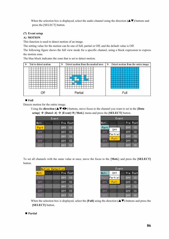
86
� When the selection box is displayed, select the audio channel using the direction ( ) buttons and press the [SELECT] button.
(7) Event setup A) MOTION This function is used to detect motion of an image. The setting value for the motion can be one of full, partial or Off, and the default value is Off. The following figure shows the full view mode for a specific channel, using a block expression to express the motion zone. The blue block indicates the zone that is set to detect motion.
Full Detects motion for the entire image.
� Using the direction ( ) buttons, move focus to the channel you want to set in the {Data setup} {Data1~4} {Event} { Moti.} menu and press the [SELECT] button.
To set all channels with the same value at once, move the focus to the {Moti.} and press the [SELECT] button.
� When the selection box is displayed, select the [Full] using the direction ( ) buttons and press the
[SELECT] button.
Partial

87
Detects motion only within the zone the user has set. � Using the direction ( ) buttons, move to the channel you want to set in the {Recording
setup} {Data1~4} {Event} {Moti.} menu and press the [SELECT] button.
To set all channels with the same value at once, move the focus to the {Moti.} and press the [SELECT] button.
� When the selection box is displayed, select the [Partial] button using the direction ( ) buttons
and press the [SELECT] button. � Then, the following zone selection screen is displayed.
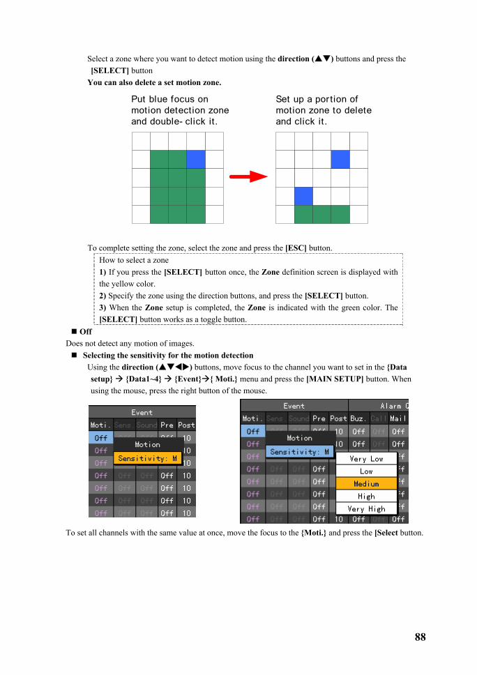
88
� Select a zone where you want to detect motion using the direction ( ) buttons and press the [SELECT] button
� You can also delete a set motion zone.
Put blue focus on motion detection zoneand double- click it.
Set up a por tion of motion zone to delete and click it.
� To complete setting the zone, select the zone and press the [ESC] button. How to select a zone 1) If you press the [SELECT] button once, the Zone definition screen is displayed with the yellow color. 2) Specify the zone using the direction buttons, and press the [SELECT] button. 3) When the Zone setup is completed, the Zone is indicated with the green color. The [SELECT] button works as a toggle button.
Off Does not detect any motion of images.
Selecting the sensitivity for the motion detection � Using the direction ( ) buttons, move focus to the channel you want to set in the {Data
setup} {Data1~4} {Event} { Moti.} menu and press the [MAIN SETUP] button. When using the mouse, press the right button of the mouse.
To set all channels with the same value at once, move the focus to the {Moti.} and press the [Select button.
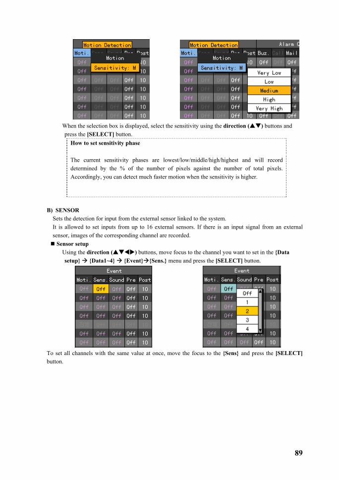
89
� When the selection box is displayed, select the sensitivity using the direction ( ) buttons and
press the [SELECT] button. How to set sensitivity phase
The current sensitivity phases are lowest/low/middle/high/highest and will record determined by the % of the number of pixels against the number of total pixels. Accordingly, you can detect much faster motion when the sensitivity is higher.
B) SENSOR
Sets the detection for input from the external sensor linked to the system. It is allowed to set inputs from up to 16 external sensors. If there is an input signal from an external sensor, images of the corresponding channel are recorded. Sensor setup � Using the direction ( ) buttons, move focus to the channel you want to set in the {Data
setup} {Data1~4} {Event} {Sens.} menu and press the [SELECT] button.
To set all channels with the same value at once, move the focus to the {Sens} and press the [SELECT] button.

90
� When the selection box is displayed, select the No. of input terminal of the external sensor box using
the direction ( ) buttons and press the [SELECT] button. Sensor type setup � Using the direction ( ) buttons, move focus to the channel you want to set in the {Data
setup} {Data1~4} {Event} {Sens.} menu and press the [MAIN SETUP] button.
To set all channels with the same value at once, move the focus to the {Sens.} and press the [MAIN SETUP] button.
� When the selection box is displayed, select the sensor type using the direction ( ) buttons and
press the [SELECT] button. NC (Normal Close): It normally stays in the closed mode although it is opened once a signal is received. NO (Normal Open): It normally stays in the opened mode although it is closed once a signal is received.

91
C) SOUND Sets the detection for input from the external audio linked to the system. It is allowed to set inputs from up to 16 external audio lines linked to the system. If there is an input signal from an external audio signal, images of the corresponding channel are recorded. Each channel can detect 1 to 16 external audio signals.
� Using the direction ( ) buttons, move focus to the channel you want to set in the {Data setup} {Data1~4} {Event} {Sound} menu and press the [SELECT] button.
To set all channels with the same value at once, move the focus to the {Sound} and press the [SELECT] button.
� When the selection box is displayed, select the audio channel using the direction ( ) buttons and
press the [SELECT] button. � The setup for the detection for more than one external audio input is as follows.

92
To control the sensitivity of the sound at each channel, move the focus to the {Sound} and press the [MAIN SETUP] button.
� When the selection box is displayed, select the audio channel using the direction ( ) buttons and press the [SELECT] button.
D)Recording before an event This function, when recording for Motion, Sensor or Sound event, is used to record image information before an event occurs. It records images at several seconds before an event occurs, as shown in the following figure.
PostPre
Event
When the record type is Auto, the PRE ALARM function is not supported. Post is the time duration that that will continue recording after the event ends.
� Using the direction ( ) buttons, move focus to the channel you want to set in the {Data setup} {Data1~4} {Event} {Pre} menu and press the [SELECT] button.
To set all channels with the same value at once, move the focus to the {Pre} and press the [SELECT] button.
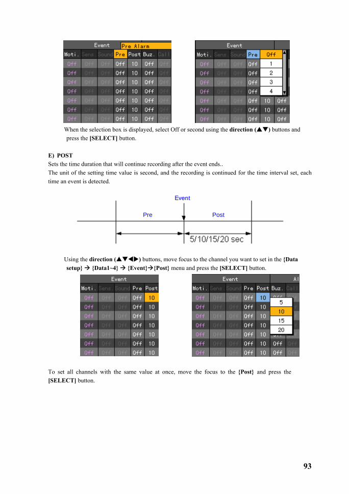
93
� When the selection box is displayed, select Off or second using the direction ( ) buttons and
press the [SELECT] button. E) POST Sets the time duration that will continue recording after the event ends.. The unit of the setting time value is second, and the recording is continued for the time interval set, each time an event is detected.
PostPre
Event
� Using the direction ( ) buttons, move focus to the channel you want to set in the {Data
setup} {Data1~4} {Event} {Post} menu and press the [SELECT] button.
To set all channels with the same value at once, move the focus to the {Post} and press the [SELECT] button.

94
� When the selection box is displayed, select the time you want to set using the direction ( )
buttons and press the [SELECT] button. (8) Alarming This function, when an event occurs, is used to notify you through a buzzer, phone call, email, spot monitor or relay. A) BUZZER When an event occurs, this function starts a buzzer in the DVR. This function works with Motion, Sensor or Sound recordings.
� Using the direction ( ) buttons, move focus to the channel you want to set in the {Data setup} {Data1~4} {Alarming} {Buz.} menu and press the [SELECT] button.
To set all channels with the same value at once, move the focus to the {Buz.} and press the
[SELECT] button.
� When the selection box is displayed, select On or Off using the direction ( ) buttons and press
the [SELECT] button.
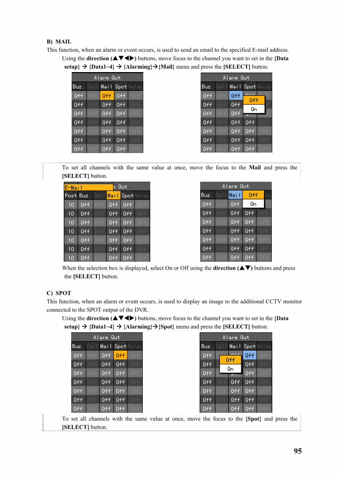
95
B) MAIL This function, when an alarm or event occurs, is used to send an email to the specified E-mail address.
� Using the direction ( ) buttons, move focus to the channel you want to set in the {Data setup} {Data1~4} {Alarming} {Mail} menu and press the [SELECT] button.
To set all channels with the same value at once, move the focus to the Mail and press the
[SELECT] button.
� When the selection box is displayed, select On or Off using the direction ( ) buttons and press
the [SELECT] button. C) SPOT This function, when an alarm or event occurs, is used to display an image to the additional CCTV monitor connected to the SPOT output of the DVR.
� Using the direction ( ) buttons, move focus to the channel you want to set in the {Data setup} {Data1~4} {Alarming} {Spot} menu and press the [SELECT] button.
To set all channels with the same value at once, move the focus to the {Spot} and press the
[SELECT] button.

96
� When the selection box is displayed, select On or Off using the direction ( ) buttons and press
the [SELECT] button. D) RELAY This function, when an alarm or event occurs, is used to activate the alarm device connected to the DIO board of the equipment.
Relay setup � Using the direction ( ) buttons, move focus to the channel you want to set in the {Data
setup} {Data1~4} {Alarming} {Relay} menu and press the [SELECT] button.
To set all channels with the same value at once, move the focus to the {Relay} and press the [SELECT] button.
� When the selection box is displayed, select On or Off using the direction ( ) buttons and press
the [SELECT] button. Selecting a relay type

97
� Using the direction ( ) buttons, move focus to the channel you want to set in the {Data setup} {Data1~4} {Alarming} {Relay} menu and press the [MAIN SETUP] button.
To set all channels with the same value at once, move the focus to the {Relay} and press the
[SELECT] button.
� When the selection box is displayed, select the relay type using the direction ( ) buttons and
press the [SELECT] button. ��-���-���Recording schedule
{Recording schedule} is a function that saves the system setting as data ranges from 1 to 4 and assigns each of the data set as time/day of the week before it starts recording accordingly.
In order to apply the changed settings in the record schedule menu, save it before using it. [Holiday]
Specifies a holiday. [Save] Saves settings. [Cancel] Does not save settings. [Reset] Clears all previous settings and restores default values.
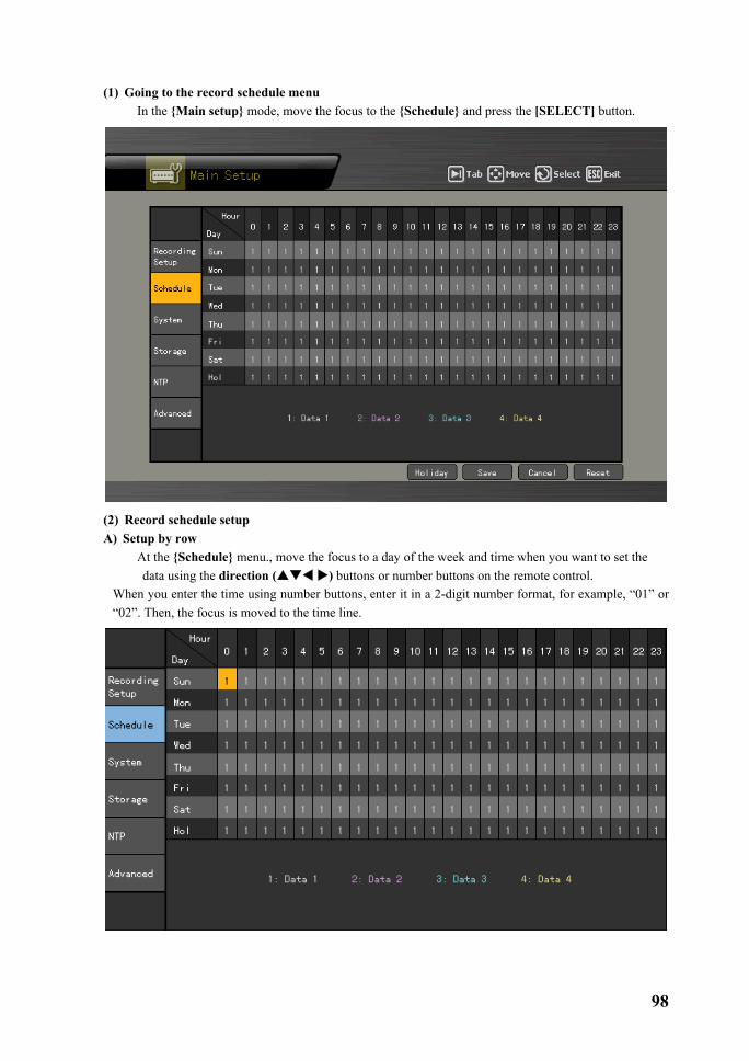
98
(1) Going to the record schedule menu � In the {Main setup} mode, move the focus to the {Schedule} and press the [SELECT] button.
(2) Record schedule setup A) Setup by row
� At the {Schedule} menu., move the focus to a day of the week and time when you want to set the data using the direction ( ) buttons or number buttons on the remote control.
When you enter the time using number buttons, enter it in a 2-digit number format, for example, “01” or “02”. Then, the focus is moved to the time line.

99
� Select the time when you want to set the data. a) To set only the selected time, press the [Main Setup] button on the remote control.
When using the mouse, press the right mousebutton. b) To set all rows since to the selected time at once, press the [SELECT] button.
When using the mouse, double-click it. � When the selection box is displayed, move the focus to the data that will be set at the selected time
using the direction ( ) buttons and press the [SELECT] button.
� When you select the time, the data is set depending on the button you press.
a) When you pressed the [Main Setup] button, The specified data is set only at the selected time.
b) When you pressed the [SELECT] button,
The data specified after the selected time is set.
B) Setup by column � In the {Schedule} menu., move the focus to the time row when you want to set the data using the

100
direction ( ) buttons or number buttons on the remote control. When you enter the time using number buttons, enter it in a 2-digit number format, for example, “01” or “02”.
� Select the time when you want to set the data. a) To set only one column of the selected time, press the [Main Setup] button on the remote control. When using the mouse, right-click it. b) To set all columns and rows since the selected time at once, press the [SELECT] button.
When using the mouse, double-click it. � When the selection box is displayed, move the focus to the data that will be set at the row or column
of selected time using the direction ( ) buttons and press the [SELECT] button.

101
� When you select the time, the data is set depending on the button you press. • When you pressed [Main Setup] the button,
Only the data specified at one column of the selected time is set.
• When you pressed the [SELECT], The data specified at all columns and rows after the selected time is set.

102
C) Holiday setup This function allows the user to specify a holiday. When the date of a holiday and a day of the week, on the {Record schedule}, are the same, data setup for the holiday takes priority. Calendar
The specified holiday is indicated with the red tag.
Holiday list All of set holidays are listed. Each page includes 15 days.
Holiday information Shows details on the selected date. {Page}, when the holiday list is more than 15 days, indicate the number of page. {Current page number/number of total pages}
The {Holiday No.} is No. of holidays numbered in order of date.
{Selected holiday No./The number of totalholidays} {Date} indicates the data specified to theholiday.
� Move the focus to the [Holiday] button on the bottom of the menu using the [TAB] button and direction ( ) buttons in the {Record schedule} menu, and press the [SELECT] button.
� When the{holiday registration window} is displayed, move the focus to the date you want to set as a
holiday using the direction ( ) buttons and press the [SELECT] button.
� After you finished specifying the date as a holiday, move the focus to the [Save] button of the bottom of the menu and press the [SELECT] button. [Save] Saves the specified holiday. [Cancel] Exits without saving the settings. [Reset] Clears all previous settings and restores default values.

103
��-���-���System
The {System} menu allows you to perform the following system settings and additional functions of the system. 1. {Local Admin Password} Sets the password for the local system administrator. 2. {Menu Time Out} Sets the time to go back to the real-time monitoring screen from the
system setup menu. 3. {Modem Baud Rate} Sets the communication speed of the modem device. 4. {DVR name} Sets the name of the DVR. 5. {Remote ID} Sets the unique number for the remote control you will use for the
system operation. 6. {Date Display Type} Sets the date format. 7. {Users} Registers, adds and deletes users. 8. {Buzzer} System buzzer On/Off 9. {Alarm Duration} Sets the time when the alarm will sound. 10. {Firmware Upgrade} System firmware upgrade 11. {Audio board type} Selects an audio board (4/8/16ch). 12. {Factory Setup} Restores initial values.
(1) Going to the system menu
� At the {Main setup}, move the focus to {System} and press the [SELECT] button.

104
(2) Local admin password Local Admin The system administrator who operates the system locally. Initial
password is “00000”. This account has a right to use all functions including system setup, system power On/Off, system monitoring and recording screen viewing.
�However, you can not access the system remotely with this account. � Move the focus to the {1. Local Admin Password} text box using the direction ( ) buttons in
the {System} menu, and press the [SELECT] button.
� When the password input window is displayed, enter the password using number buttons on the
remote control, or direction ( ) buttons and press the [SELECT] button. Max. length of the password is 5 digits.
BS Deletes one letter backward
Cancel Cancel saving Save & Exit Saves & Exits
� When you finished entering the password, move the focus to the [Save & Exit] using the [TAB] button or direction ( ) buttons and press the [SELECT] button.
(3) Menu Time Out This function is used to set the time to go to the real time monitoring mode automatically when there is no input from the touch pad, remote control or mouse for a specific time interval at the system setup menu. (4) Move the focus to the {2. Menu Time Out} selection box using the direction ( ) buttons in the {System} menu, and press the [SELECT] button.
� When the selection box is displayed, select the time you want to set using the direction ( )
buttons and press the [SELECT] button.
Off Does not use the automatic menu exit function. - Exit the menu using the ESC button at the system menu.

105
10/20/30 seconds If there is no input from the touch pad, remote control or mouse for each setting time, it is switched back to the real time monitoring mode.
User setup The user enters the time directly. -The time range the user can set is 5 to 99.
� If you select the User setup, the following time input window is displayed.
BS Deletes one letter backward Cancel Cancels saving Save & Exit Saves & Exits
� Enter the time using the direction ( ) buttons and press the [SELECT] button or number buttons on the remote control.
� When you have finished entering, move the focus to the [Save & Exit] using the [TAB] button or direction ( ) buttons and press the [SELECT] button.
(5) Modem Baud Rate When using a modem, sets the transmission speed of the modem.
� Move the focus to the {3. Modem Baud Rate} selection box using the direction ( ) buttons in the {System} menu, and press the [SELECT] button.
-For more information on the transmission speed of a modem, please refer to the manual related to that modem.
� When the selection box is displayed, select a transmission speed of the modem you want to use using the direction ( ) buttons and press the [SELECT] button.
(6) Changing the DVR name � Move the focus to the {4. DVR name} text box using the direction ( ) buttons at the {System}
menu, and press the [SELECT] button.

106
� When the name input window is displayed, enter a name using the number buttons on the remote control, or direction ( ) buttons and press the [SELECT] button.
Caps Lock Switches between
upper/lower cases BS Deletes one letter backward Space Inserts a space. Cancel Cancels saving Save & Exit Saves & Exits
� When you have finished entering the name, move the focus to the [Save & Exit] using the [TAB] button or direction ( ) buttons and press the [SELECT] button.
Max. length of the system name is 20 letters. (7) Remote control ID When using several DVRs, sets the remote control ID that identifies the input signal of the remote control. Only When theDVR ID and remote control ID, as shown in the following figure, are the same, will the input signal of the remote control be accepted.
� Move the focus to the {Remote ID} selection box using the direction ( ) buttons in the
{System} menu, and press the [SELECT] button.
� When the ID input window is displayed, enter the ID using the number buttons on the remote control,
or direction ( ) buttons and press the [SELECT] button. ID is only available within 0~99.

107
BS Deletes one letter backward Cancel Cancels saving Save & Exit Saves & Exits
� When you have finished entering the ID, move the focus to the [Save & Exit] using the [TAB] button or direction ( ) buttons and press the [SELECT] button.
� After you finished setting the remote control ID of the DVR, change the ID of the remote control to the one set in the DVR.
Press the [ID] button, press a two-digit number for the remote control ID and press the [ID] button again.
Set the remote control ID to 999 to control all DVRS, each of which has different a DVR ID.
(8) Date Display Type
� Move the focus to the {6. Date Display Type} selection box using the direction ( ) buttons in the {System} menu, and press the [SELECT] button.
� When the selection box is displayed, select the date format using the direction ( ) buttons and
press the [SELECT] button.
, ,

108
(9) Users Registers/modifies/deletes a user who will operate the system.
System Permissions Network Live Real- time screen view Network play Record screen view Download network file Network access and file download Main setup Data, Schedule, System setup App. setup PTZ camera, network setup Network PTZ Control PTZ camera control Network backup Backup function Remote upgrade Remote upgrade
A) Modifying the user information
� Move the focus to the {7. Users}→{Modify} using the direction ( ) buttons in the {System} menu, and press the [SELECT] button.
� When the user selection box is displayed, select the user you want to modify using the direction
( ) buttons and press the [SELECT] button.
� When the permission setup window for use of the system functions are displayed as in the following figure, select the permissions of the user using the direction ( ) button and press the [SELECT] button.
Enables permissions for that function.
Disables permissions for that function.
� When you have finished setting permissions for that user, move the focus to [Modify] using the [TAB] button or direction ( ) buttons and press the [SELECT] button.
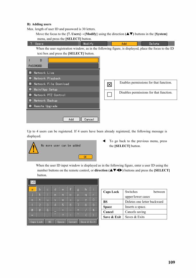
109
B) Adding users Max. length of user ID and password is 30 letters.
� Move the focus to the {7. Users}→{Modify} using the direction ( ) buttons in the {System} menu, and press the [SELECT] button.
� When the user registration window, as in the following figure, is displayed, place the focus to the ID
text box and press the [SELECT] button.
Enables permissions for that function.
Disables permissions for that function.
Up to 4 users can be registered. If 4 users have been already registered, the following message is displayed.
To go back to the previous menu, press the [SELECT] button.
� When the user ID input window is displayed as in the following figure, enter a user ID using the number buttons on the remote control, or direction ( ) buttons and press the [SELECT] button.
Caps Lock Switches between upper/lower cases
BS Deletes one letter backward Space Inserts a space. Cancel Cancels saving Save & Exit Saves & Exits

110
� When you finished entering, move the focus to the [Save & Exit] using the [TAB] button or direction ( ) buttons and press the [SELECT] button.
� After you set the user ID, move the focus to the password text box using the direction ( ) buttons, and press the [SELECT] button.
Enables permissions for that function.
Disables permissions for that function.
� When the password input window is displayed, enter a password using number buttons on the remote control, or direction ( ) buttons and press the [SELECT] button. Max. length of the password is 30 letters.
BS Deletes one letter backward Cancel Cancels saving Save & Exit Saves & Exits
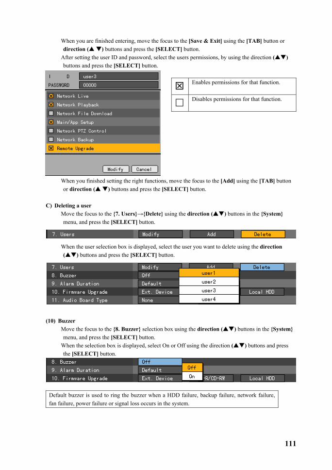
111
� When you are finished entering, move the focus to the [Save & Exit] using the [TAB] button or direction ( ) buttons and press the [SELECT] button.
� After setting the user ID and password, select the users permissions, by using the direction ( ) buttons and press the [SELECT] button.
Enables permissions for that function.
Disables permissions for that function.
� When you finished setting the right functions, move the focus to the [Add] using the [TAB] button or direction ( ) buttons and press the [SELECT] button.
C) Deleting a user
� Move the focus to the {7. Users}→{Delete} using the direction ( ) buttons in the {System} menu, and press the [SELECT] button.
� When the user selection box is displayed, select the user you want to delete using the direction ( ) buttons and press the [SELECT] button.
(10) Buzzer
� Move the focus to the {8. Buzzer} selection box using the direction ( ) buttons in the {System} menu, and press the [SELECT] button.
� When the selection box is displayed, select On or Off using the direction ( ) buttons and press the [SELECT] button.
Default buzzer is used to ring the buzzer when a HDD failure, backup failure, network failure, fan failure, power failure or signal loss occurs in the system.
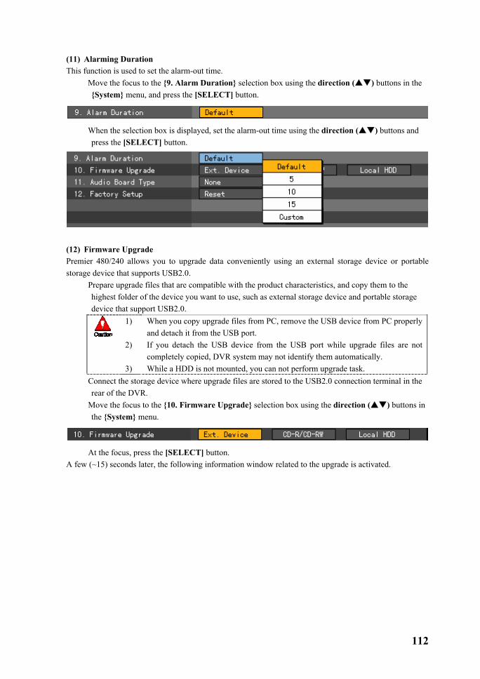
112
(11) Alarming Duration This function is used to set the alarm-out time.
� Move the focus to the {9. Alarm Duration} selection box using the direction ( ) buttons in the {System} menu, and press the [SELECT] button.
� When the selection box is displayed, set the alarm-out time using the direction ( ) buttons and press the [SELECT] button.
(12) Firmware Upgrade Premier 480/240 allows you to upgrade data conveniently using an external storage device or portable storage device that supports USB2.0.
� Prepare upgrade files that are compatible with the product characteristics, and copy them to the highest folder of the device you want to use, such as external storage device and portable storage device that support USB2.0.
1) 2) 3)
When you copy upgrade files from PC, remove the USB device from PC properly and detach it from the USB port. If you detach the USB device from the USB port while upgrade files are not completely copied, DVR system may not identify them automatically. While a HDD is not mounted, you can not perform upgrade task.
� Connect the storage device where upgrade files are stored to the USB2.0 connection terminal in the rear of the DVR.
� Move the focus to the {10. Firmware Upgrade} selection box using the direction ( ) buttons in the {System} menu.
� At the focus, press the [SELECT] button. A few (~15) seconds later, the following information window related to the upgrade is activated.

113
� If you select the [Yes] button after seeing the information contents, sequential upgrades proceed as in the following figures. To go back to the {System} mode, press the [No] button.
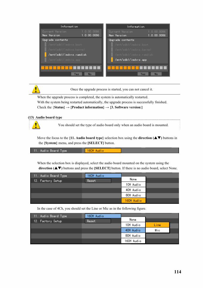
114
Once the upgrade process is started, you can not cancel it.
� When the upgrade process is completed, the system is automatically restarted. � With the system being restarted automatically, the upgrade process is successfully finished. � Check the {Status} → {Product information} → {3. Software version:}
(13) Audio board type
You should set the type of audio board only when an audio board is mounted.
� Move the focus to the {11. Audio board type} selection box using the direction ( ) buttons in
the {System} menu, and press the [SELECT] button.
� When the selection box is displayed, select the audio board mounted on the system using the
direction ( ) buttons and press the [SELECT] button. If there is no audio board, select None.
� In the case of 4Ch, you should set the Line or Mic as in the following figure.
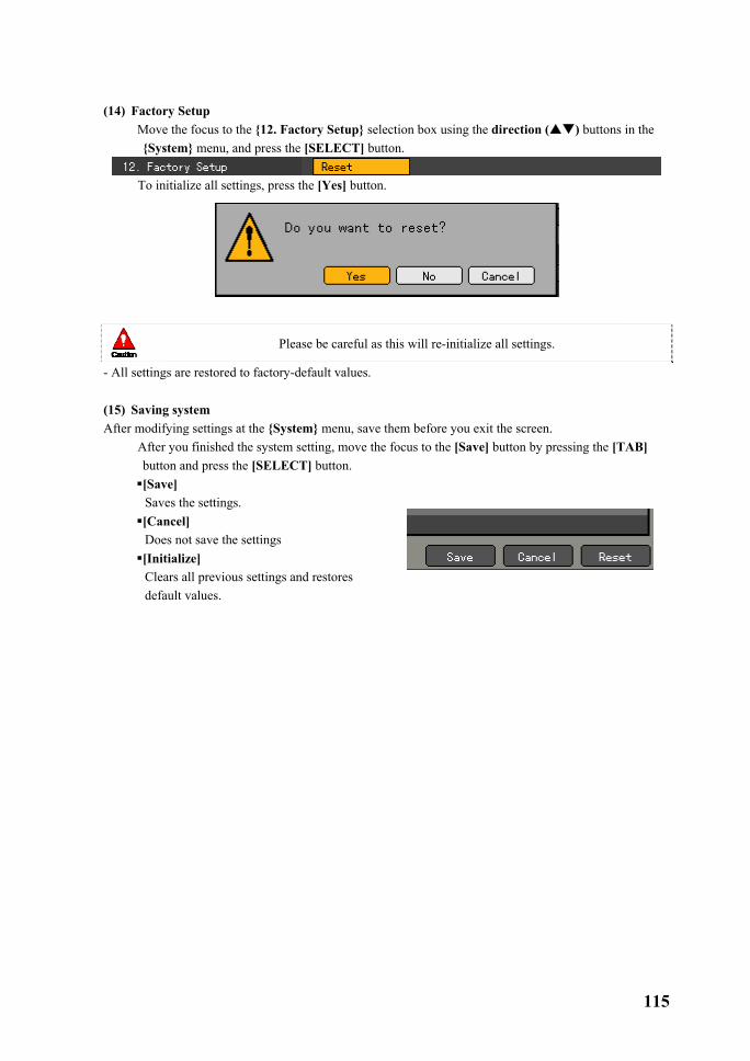
115
(14) Factory Setup
� Move the focus to the {12. Factory Setup} selection box using the direction ( ) buttons in the {System} menu, and press the [SELECT] button.
� To initialize all settings, press the [Yes] button.
Please be careful as this will re-initialize all settings.
- All settings are restored to factory-default values. (15) Saving system After modifying settings at the {System} menu, save them before you exit the screen.
� After you finished the system setting, move the focus to the [Save] button by pressing the [TAB] button and press the [SELECT] button. [Save] Saves the settings. [Cancel] Does not save the settings [Initialize] Clears all previous settings and restores default values.
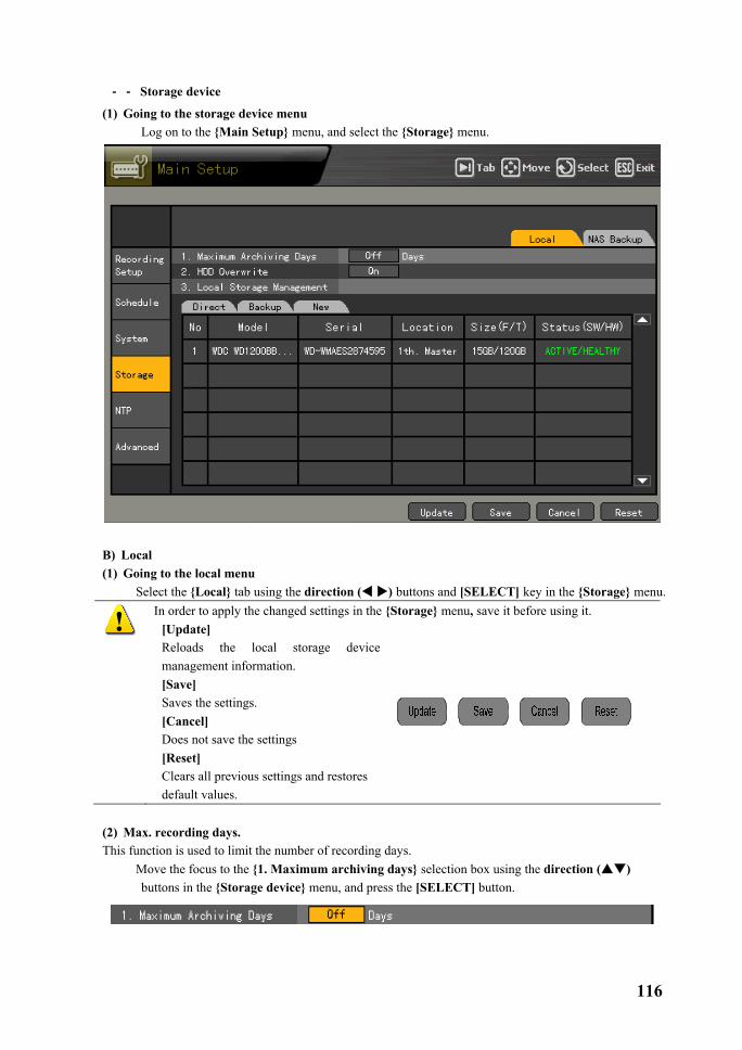
116
��-���-���Storage device
(1) Going to the storage device menu � Log on to the {Main Setup} menu, and select the {Storage} menu.
B) Local (1) Going to the local menu
� Select the {Local} tab using the direction ( ) buttons and [SELECT] key in the {Storage} menu.
In order to apply the changed settings in the {Storage} menu, save it before using it. [Update] Reloads the local storage device management information. [Save] Saves the settings. [Cancel] Does not save the settings [Reset] Clears all previous settings and restores default values.
(2) Max. recording days. This function is used to limit the number of recording days.
� Move the focus to the {1. Maximum archiving days} selection box using the direction ( ) buttons in the {Storage device} menu, and press the [SELECT] button.

117
� When the number input window is displayed, enter the number of recording days using number buttons on the remote control, or direction ( ) buttons and press the [SELECT] button.
Identifies only 1 to 31, which means the number of days. If you set more than 31, the following warning message is displayed.
(3) HDD Overwrite This function is used to switch On//Off the HDD overwriting.
� Move the focus to the {2. HDD Overwrite} selection box using the direction ( ) buttons in the {Storage} menu, and press the [SELECT] button.
� When the selection box is displayed, select On or Off using the direction ( ) buttons and press the [SELECT] button.
ON If there is no free space in HDD, the overwriting begins again with the oldest image.
OFF If there is no free HDD space, no more recording will occur.

118
(4) Local Storage Management � Use direction ( ) buttons at the {Storage} menu to select the {3. Local Storage Management} � {3. Local Storage Management } includes 3 types as follows; {Direct}, {Backup} and {New}.
The local storage device includes devices, such as HDDs that store data in real time and storage devices connected to USB or IEEE1394 that are used for back up purposes only. The local storage device is divided into {New}, {Direct} and {Backup}, providing these functions.
� New Storage device manager that can set a storage device searched at {New} to the direct recording storage device or backup storage device. - {Direct} : Sets the selected storage device as a direct recording storage device.
- { Backup} : Sets the selected storage device as a backup storage device. � Direct The direct recording indicates the type in which the data is stored on HDDs in real-time. In the {Direct} mode, 5 commands can be performed. However, there is an order impossible to perform depending on the S/W status. - {New} : Restores the selected storage device to a New status. With this command, the selected storage device moves to the {New} storage device manager. - {Online}: sets the selected storage device to the online status. - {Offline}: sets the selected storage device to the offline status. - {Format}: formats the selected storage device. - {Eject} : separates the selected storage device completely.
Healthy and Warning are hardware statuses that can perform those roles above, and the Fault status does not perform any command.
1. Although the selected storage device, with the Offline status, does not perform recoding, the Eject plays a role of separating the selected storage device completely. Accordingly to remove a storage device connected to the USB or IEEE1394, use the {Eject} command for the device.
� Backup It manages a storage device available for backup. Storage devices listed in the {Backup} mode can not perform the direct recording, meaning that these devices can be used only for the backup of stored recording files. In the {Backup} mode, only the {New} command can be performed. The function is the same as the {New} function of {Direct}.
1. When you install storage devices, they are listed in the {New} mode. To perform recording, select one or more of them as the direct recording storage device.
2. Depending on the storage device, it may only be applied to one function of Direct or Backup.

119
(5) Configuring management of the local storage device � {Model} : Model name of the storage device. � {Serial} : Serial number of the storage device. � {Location} : The position of the storage device � {Capacity (T/F)} : Capacity of the storage device. (T : Total , F : Free) � {Status (SW/HW)} : Status of the storage device. (SW : Software, HW : Hardware)
The Software Status is described as follows; - Active : The storage device is connected to DVR, and it is performing recording task.
- Online : The storage device is connected to the DVR. But, it does not perform recording tasks now. - Offline : The storage device is not connected to the DVR.
The hardware status is described as one of three conditions, including; - Healthy : The storage device is connected to the DVR, and it is performing normal recording tasks.
- Warning: The storage device is connected to the DVR, but there is an error. In this case, the recording task may not be performed normally (for more information, refer to cautions described later in this guide. - Fault : The storage device is not connected to the DVR, and any task can not be performed because it is damaged.
� {Device type} : Replaces the {Status(SW/HW)} of the {Direct} in the {Backup} or {New} mode. Shows the status of the storage device.
(6) Adding a local storage device
� Open the cover of the DVR body, connect the drive to the IDE (or SATA) cable and connect the power cable.
� Switch on the DVR power and boot the system. � Press the [Main Setup] button, enter the password for the ID, and select {Storage}→{Local} using
the direction ( ) buttons in the {Storage} menu. � At the {New} tab, you can see the information on the newly installed drive as in the following figure.
1. Fault status : Because the storage device was completely damaged, it is not possible to perform any S/W tasks.
The fault status is not associated with the failure of DVR, and the DVR stops the recording task by detecting the failure of the storage device. 2. Warning status : Although there is a physical error in the storage device, it can
be compensated with the device and DVR’s error compensation function. When the storage device, however, leaves as it is, it may completely fail(Fault status). It is strongly recommended to back up the data of the corresponding storage device and replace it.
3. When the Active storage device is in the Warning or Fault status, an alarm message is displayed at the left-middle side of the screen. When the user sees this message in the {Log}, it is not displayed any more because the DVR considers it a known status.
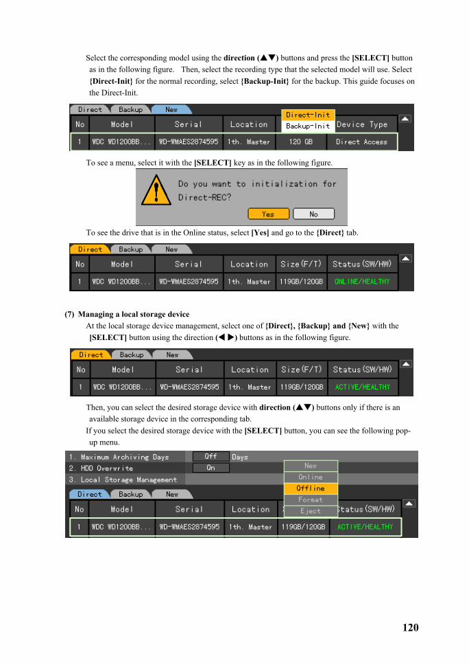
120
� Select the corresponding model using the direction ( ) buttons and press the [SELECT] button as in the following figure. Then, select the recording type that the selected model will use. Select {Direct-Init} for the normal recording, select {Backup-Init} for the backup. This guide focuses on the Direct-Init.
� To see a menu, select it with the [SELECT] key as in the following figure.
� To see the drive that is in the Online status, select [Yes] and go to the {Direct} tab.
(7) Managing a local storage device
� At the local storage device management, select one of {Direct}, {Backup} and {New} with the [SELECT] button using the direction ( ) buttons as in the following figure.
� Then, you can select the desired storage device with direction ( ) buttons only if there is an available storage device in the corresponding tab.
� If you select the desired storage device with the [SELECT] button, you can see the following pop-up menu.

121
� Run the item by selecting it with direction ( ) buttons and press the [SELECT] button. � All commands prompts the user to confirm once more as in the following figure.
� To run the corresponding menu, select [Ok].
B) NAS backup (1) Going to the NAS backup menu
� Log on to the {Main Setup} menu, and select the {Storage}→{NAS backup} menu.
(2)Using NAS
� Move the focus to the {NAS Backup} →{1. NAS Use } selection box using the direction ( ) buttons in the {Storage} menu, and press the [SELECT] button.

122
� When the selection box is displayed, select On or Off using the direction ( ) buttons and press the [SELECT] button.
� If you select either On or Test, the following Test task is carried out.
(3) ID
� Move to the {2. ID} menu using the direction ( ) buttons, and press the [SELECT] button. � When the title input box is displayed as in the following figure, enter an ID using the direction
( ) buttons and press the [SELECT] button.
Caps Lock Switch between upper/lower cases
BS Deletes one letter backward
Space Inserts a space Cancel Cancels saving Save & Exit Saves & Exits
� After you finished entering the channel name, move the focus to [Save& Exit] using the direction ( ) buttons or [TAB] button, and press the [SELECT] button to save the settings.
(4) Password
� Move to the {3. Password} menu using the direction ( ) buttons, and press the [SELECT] button.
� When the title input box is displayed as in the following figure, enter a password using the direction ( ) buttons and press the [SELECT] button.
Caps Lock Switches between upper/lower cases
BS Deletes one letter backward
Space Inserts a space Cancel Cancels saving Save & Exit Saves & Exits
� After you finished entering the channel name, move the focus to [Save& Exit] using the direction

123
( ) buttons or [TAB] button, and press the [SELECT] button to save the settings. (5) IP
� Move to the {4. IP} menu using the direction ( ) buttons, and press the [SELECT] button. � When the title input box is displayed as in the following figure, enter an IP using the direction
( ) buttons and press the [SELECT] button.
(6) Directory
� Move to the {5. Directory} menu using the direction ( ) buttons, and press the [SELECT] button.
� When the title input box is displayed as in the following figure, enter a directory using the direction ( ) buttons and press the [SELECT] button.
Caps Lock Switch between upper/lower cases
BS Deletes one letter backward
Space Inserts a space Cancel Cancels saving Save & Exit Saves & Exits
� After you finished entering the channel name, move the focus to [Save& Exit] using the direction ( ) buttons or [TAB] button, and press the [SELECT] button to save the settings.
(7) Run time
� Move to the {6. Run time} menu using the direction ( ) buttons, and press the [SELECT] button.
� When the title input box is displayed as in the following figure, enter a run time using the direction ( ) buttons and press the [SELECT] button.
Caps Lock Switch between upper/lower cases
BS Deletes one letter backward
Space Inserts a space Cancel Cancels saving Save & Exit Saves & Exits

124
Identifies only 1 to 59 for minutes. If you set it over 59, the following warning message is displayed.
(8) Max. Save Time
� Move the focus to the {NAS Backup} → {7. Max. Save Time } selection box using the direction ( ) buttons in the {Storage} menu, and press the [SELECT] button.
� When the selection box is displayed, select 1 or 2 hours using the direction ( ) buttons and press
the [SELECT] button.
(8) Min. Spare Space
� Move the focus to the {8. Min. Spare Space} menu using the direction ( ) buttons, and press the [SELECT] button.
� When the title input box is displayed as in the following figure, enter the min. free space using the direction ( ) buttons and press the [SELECT] button.
Identifies only 10 to 100 in gigabytes. If you set it to over 100, the following warning message is displayed.
(9) Overwrite This function is used to switch On/Off the NAS overwriting.
� Move the focus to the {NAS Backup} →{9. Overwrite} selection box using the direction ( ) buttons in the {Storage} menu, and press the [SELECT] button.
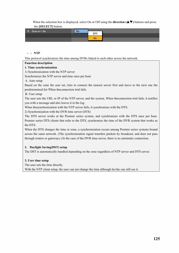
125
� When the selection box is displayed, select On or Off using the direction ( ) buttons and press the [SELECT] button.
��-���-���NTP
This protocol synchronizes the time among DVRs linked to each other across the network. Function description 1. Time synchronization 1) Synchronization with the NTP server Synchronizes the NTP server and time once per hour A. Auto setup Based on the zone the user set, tries to connect the nearest server first and move to the next one the predetermined list When theconnection trial fails. B. User setup The user sets the URL or IP of the NTP server, and the system, When theconnection trial fails, it notifies you with a message and also leaves it in the log. When thesynchronization with the NTP server fails, it synchronizes with the DTS. 2) Synchronization with the DVR time server (DTS) The DTS server works at the Premier series system, and synchronizes with the DTS once per hour. Premier series DTS clients that refer to the DTS, synchronize the time of the DVR system that works as the DTS. When the DTS changes the time or zone, a synchronization occurs among Premier series systems bound across the same network. (The synchronization signal transfers packets by broadcast, and does not pass through routers or gateways.) In the case of the DVR time server, there is no automatic connection. 2. Daylight Saving(DST) setup The DST is automatically handled depending on the zone regardless of NTP server and DTS server. 3. User time setup The user sets the time directly. With the NTP client setup, the user can not change the time although he/she can still see it.

126
(1) Going to the NTP menu � Log on to the {Main Setup} menu, and select the {NTP} menu.
(2) NTP mode
� Move the focus to the {1. NTP mode} selection box using the direction ( ) buttons in the {NTP} menu, and press the [SELECT] button.
� When the selection box is displayed, select the NTP mode using the direction ( ) buttons and
press the [SELECT] button.
OFF Does not use the NTP. Server Works as the DTR time server. Client Works as the DTS client, and synchronizes the time of the server.
A) Setting the server type It is settable only When the {NTP mode} is the client, and is used to select the NTP server or DVR time server.
� Move the focus to the {1.1. Server type} selection box using the direction ( ) buttons in the {NTP} menu, and press the [SELECT] button.
� When the selection box is displayed, select the server type using the direction ( ) buttons and

127
press the [SELECT] button.
B) Server URL It is settable only when the NTP mode is the client, and used to set the address of the NTP server or DVR time server.
� Move the focus to the {1.2. Server URL} selection box using the direction ( ) buttons in the {NTP} menu, and press the [SELECT] button.
� When the selection box is displayed, specify the server URL using the direction ( ) buttons and press the [SELECT] button.
� When the server type is DVR, you can enter only the IP. For the NTP server, you can specify by
selecting either Automatic, IP and URL.
Auto Based on the zone the user set, tries to connect the nearest server first and move to the next one the predetermined list When the connection trial fails.
IP When the number input window id displayed, enter the IP of the server that you want to synchronize the time with.
URL
When the text input window is displayed, enter the URL of the server that you want to synchronize the time with.

128
(3) Changing the system date and time You can change the date and time only When the NTP mode is server or Off. The view format of system date and time is YEAR/MONTH/DAY HH/MM/SS, and you can set it at the {Main setup}→{System}→{6. Time format}
� Move the focus to the {2. Data and Time} text box using the direction ( ) buttons in the {NTP} menu, and press the [SELECT] button.
� Move the focus to the part you want to change in YEAR/MONTH/DAY HH/MM/SS using the direction ( ) buttons, and press the [SELECT] button.
� Change the date and time using the direction ( ) buttons, and press the [SELECT] button.
� Then, the following message is displayed and the system time is changed.
(4) Daylight Saving Time Sets the Daylight Saving Time.
A) Daylight saving time Applies the summer time.

129
� It is enabled only if you set a zone supporting DST at the standard time zone. � Move the focus to the {3.1. Daylight Saving Time} selection box using the direction ( ) buttons
in the {NTP} menu, and press the [SELECT] button.
� When the selection box is displayed, select On or Off using the direction ( ) buttons and press the [SELECT] button.
�After the DST is applied, the existing data is indicated as “OLD_” in the search and log list. �When setting the standard time, set the standard time first and then date and time. ��-���-���Advanced
This menu is used to set details on the image quality by channel. (1) Going to the Advanced menu A) Selecting menu type Move as in the following figure using the [TAB] button and direction ( ) buttons on the remote control, and press the [SELECT] button.
Configuration of advanced menu
You can set more complicated and various values by channel, as shown in the following figure. Sets the data for each channel, ranging from 1 to 16.

130
(2) Setting Advanced options by channel A) Filter
� Press the button in the {Filter} menu, move the focus to the position you want using the direction ( ) buttons and select it with the [SELECT] button as in the following figure.
B) Average filter � Press the [SELECT] button in the {Average filter} menu, move the focus to the position you want
using the direction ( ) buttons and select it with the [SELECT] button as in the following figure.
C) Comb/Trap � Press the [SELECT] button in the {Comp Trap} menu, move the focus to the position you want
using the direction ( ) buttons and select it with the [SELECT] button as in the following figure.
D) Max. bit rate � When the input box prompts you in the following figure, enter a bit rate using the direction
( ) buttons and press the [SELECT] button.
BS Deletes one letter
backward Cancel Cancels saving
Save & Exit Saves & Exits
� After you finished entering the channel name, move the focus to [Save& Exit] using the direction ( ) buttons or [TAB] button, and press the [SELECT] button to save the settings.

131
E) H Anti-Aliasing � Press the [SELECT] button in the {H Anti-Aliasing} menu, move the focus to the position you want
using the direction ( ) buttons and select it with the [SELECT] button as in the following figure.
F) V Anti-Aliasing � Press the [SELECT] button in the {V Anti-Aliasing} menu, move the focus to the position you want
using the direction ( ) buttons and select it with the [SELECT] button as in the following figure.
G) Peaking � Press the [SELECT] button in the {Peaking} menu, move the focus to the position you want using
the direction ( ) buttons and select it with the [SELECT] button as in the following figure.

132
H) C/Y Cording � Press the [SELECT] button in the {C/Y Cording} menu, move the focus to the position you want
using the direction ( ) buttons and select it with the [SELECT] button as in the following figure.
(3) Meaning of Advanced options
Menus Description {Filter} Filters images. You can select one of Deinterlace Filter and Temporal Filter,
Deinterlace Filter for the noise in still images and Temporal Filter for the noise in moving images. By default, it is general to use the Temporal Filter in the DVR because it handles moving images.
{Average filter} Two options of 1:6:1 and 1:2:1 are provided. Given 1:6:1, the cleaner image similar to the original image can be achieved although the file size gets bigger. The default value is 1:2:1.
{Comb / Trap} The Comb filter is used when the boundary line between brightness and color is not clear and it enhances the resolution of the brightness. The trap filter controls the contrast of images.
{Max. bit rate} Means the max. size of moving images. {H Anti Aliasing} Sets the horizontal anti aliasing value. In general, 4MHz provides the image
closest to the real one. {V Anti Aliasing} Sets the vertical anti aliasing value. In general, [All] option provides the
image closest to the real one. {Peaking} Peaking is the filter that emphasizes on the edge part in Y component,
providing No, 31%, 62%, 93% options. It default value is No. With 93%, the edge part is the most emphasized.
{C/Y Cording} The C/Ycoring provides the filtering that blurs the edge part of Y component, settable as one of No, +/-1, +/-2, +/-4. Its default value is No. With +/-4, the smoothest image can be achieved. As a result, it provides an output similar to that of the average filter.

133
�-�App. setup With the {App. Setup}, you can set PTZ and various network functions.
After changing settings in the {App. Setup} menu, save them before you exit the screen. [Save] Saves the settings. [Cancel] Does not save the settings. [Reset] Clears all previous settings and restores default settings.
��-���-���Going to the App. setup
� At the real-time monitoring screen, press the {APP. Setup} button on the remote control. � Then, this login screen prompts you.
� Select the account you want to log in, enter the password using number buttons on the remote control
and select [Ok]. • (The initial password of the local administrator is “00000”.) • If you press the direction ( ) buttons when the focus is on the ID selection box, another registered user ID is enabled.
� When the password is matched, this {App. setup} initial screen is displayed.

134
��-���-���PTZ setup
Sets the PTZ camera connected to the system.
Menu CH Indicates channels ranging from 1 to 16 Menu PTZ If there is a PTZ setup, indicates it with a camera icon. Camera title Title of each channel PTZ protocol Sets the protocol of communication with the PTZ camera Camera ID ID set at the PTZ camera Transmission type Type of the control cable that controls the camera(RS-485 or RS-422) Transmission speed
Communication speed (should match with the communication speed defined in the Guide for the camera.)
Preset interval Time interval to switch to the specified screen between Preset set at the tour function and next preset (unit: 5~60 seconds)
Tour Sets the tour function (tour 1 and tour 2)

135
(1) Setting the PTZ protocol PTZ protocol is the protocol to communicate with the PTZ camera.
� Move the focus to the channel you want to set in the PTZ protocol menu using the direction ( ) buttons in the PTZ setup menu, and press the [SELECT] button.
� When the selection box is displayed, select a protocol using the direction ( ) buttons and press the [SELECT] button.
(2) Setting the camera ID The camera ID is the address to communicate with the PTZ camera. • •
The camera ID should match with the address set for the PTZ camera. For more information about how to set the address of the PTZ camera, refer to the Guide of the camera because it depends on the manufacturer and model.
� Move the focus to the channel you want to set in the camera ID menu using the direction ( ) buttons in the PTZ setup menu, and press the [SELECT] button.
� When the selection box is displayed, select the camera ID using the direction ( ) buttons and press the [SELECT] button.
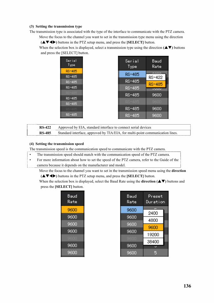
136
(3) Setting the transmission type The transmission type is associated with the type of the interface to communicate with the PTZ camera.
� Move the focus to the channel you want to set in the transmission type menu using the direction ( ) buttons in the PTZ setup menu, and press the [SELECT] button.
� When the selection box is displayed, select a transmission type using the direction ( ) buttons and press the [SELECT] button.
RS-422 Approved by EIA, standard interface to connect serial devices RS-485 Standard interface, approved by TIA/EIA, for multi-point communication lines.
(4) Setting the transmission speed The transmission speed is the communication speed to communicate with the PTZ camera. • •
The transmission speed should match with the communication speed of the PTZ camera. For more information about how to set the speed of the PTZ camera, refer to the Guide of the camera because it depends on the manufacturer and model.
� Move the focus to the channel you want to set in the transmission speed menu using the direction ( ) buttons in the PTZ setup menu, and press the [SELECT] button.
� When the selection box is displayed, select the Baud Rate using the direction ( ) buttons and press the [SELECT] button.

137
(5) Setting preset interval Preset Saves values by controlling left-right/up-down/zoom/focus of the PTZ
camera - you can save up to 8 control presets using 1 to 8.
Tour Moves the PTZ according to the preset control statuses of the PTZ camera in order of setup. � Tour1 is set to �, and Tour2 is set to �.
Preset interval Time interval for the tour. (You can select a value in the range of 5 to 60.) � Move the focus to the channel you want to set in the preset interval menu using the direction
( ) buttons in the PTZ setup menu, and press the [SELECT] button. � When the selection box is displayed, select a preset interval using the direction ( ) buttons and
press the [SELECT] button.
(6) Setting the tour Preset Saves values by controlling left-right/up-down/zoom/focus of the PTZ camera
- you can save up to 8 control presets using 1 to 8. Tour Moves the PTZ according to the preset control phases of the PTZ camera in
order of setup. � Tour1 is set to �, and Tour2 is set to �.
Preset interval Time interval for the tour. (You can select a value within the range of 5 to 60.)
Example - The tour function, when values of Tour1 and Tour2 are as follows
If you press � in the PTZ mode, it follows the order of 1 > 7 > 5 > 6. If you press � once more, the function is disabled.
If you press � in the PTZ mode, it follows the order of 3 > 2 > 4 > 8. If you press � once more, the function is disabled.
Tour1 Tour2 1 3 7 2 5 4 6 8
� Move the focus to the channel you want to set in the Tour menu using the direction ( ) buttons in the PTZ setup menu, and press the [SELECT] button.
� When the selection box is displayed, set the Tour function using the direction ( ) buttons and

138
press the [SELECT] button.
��-���-���Setting the network
(1) Going to the network setup menu � In the {App. setup} mode, move the focus to the {Network} and press the [SELECT] button.
(2) Ethernet Set it if you use a fixed IP in the local area network environment.

139
� Move the focus to the {Ethernet} using the direction ( ) buttons in the {Network} setup menu,, and press the [SELECT] button.
� Use the [TAB] button for the movement in �, �, and �, and press direction ( ) buttons to
toggle between selections.
Sets LAN for Network item in the LAN setup menu.
How to change only latter part of the existing settings at the address input window. a) Place the focus to the input box using the direction ( ) buttons, and press the {SELECT}
button. b) Move the focus to the [BS] using the [TAB] button or direction ( ) buttons. c) Delete values you want to modify by pressing the [SELECT] button. d) Enter the desired value using number buttons on the remote control, or direction ( )
buttons and press the [SELECT] button.
BS Deletes one letter backward
Cancel Cancels saving Save & Exit
Saves & Exits

140
B) IP address setup
� Move the focus to IP address input box using the direction ( ) buttons in the {Ethernet} setup menu, and press the [SELECT] button.
� When the IP address input window is displayed, enter an IP address using number buttons on the
remote control, or direction ( ) buttons and press the [SELECT] button.
BS Deletes one letter backward
Cancel Cancels saving Save & Exit Saves & Exits
� When you have finished entering the IP address, move the focus to the [Save & Exit] using the [TAB] button or direction ( ) buttons and press the [SELECT] button.
C) Subnet Mask setup
� Move the focus to Subnet Mask input box using the direction ( ) buttons in the {Ethernet} setup menu, and press the [SELECT] button.

141
� When the Subnet Mask input window is displayed, enter the subnet mask using number buttons on the remote control, or direction ( ) buttons and press the [SELECT] button.
BS Deletes one letter backward
Cancel Cancels saving Save & Exit Saves & Exits
� When you have finished entering the subnet mask, move the focus to the [Save & Exit] button using the [TAB] button and direction ( ) buttons and press the [SELECT] button.
D) Default Gateway setup
� Move the focus to the default gateway input box using the direction ( ) buttons in the {Ethernet} setup menu, and press the [SELECT] button.
� When the Default Gateway input window is displayed, enter the default gateway using number
buttons on the remote control, or direction ( ) buttons and press the [SELECT] button.
BS Deletes one letter backward
Cancel Cancels saving Save & Exit Saves & Exits
� When you finished entering the default gateway, move the focus to the [Save & Exit] button using the [TAB] button and direction ( ) buttons and press the [SELECT] button.
E) Default DNS setup � Move the focus to the default DNS input box using the direction ( ) buttons in the {Ethernet}
setup menu, and press the [SELECT] button.
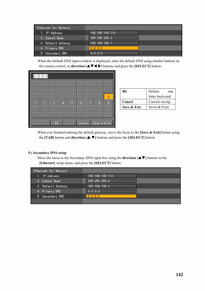
142
� When the Default DNS input window is displayed, enter the default DNS using number buttons on
the remote control, or direction ( ) buttons and press the [SELECT] button.
BS Deletes one letter backward
Cancel Cancels saving Save & Exit Saves & Exits
� When you finished entering the default gateway, move the focus to the [Save & Exit] button using the [TAB] button and direction ( ) buttons and press the [SELECT] button.
F) Secondary DNS setup
� Move the focus to the Secondary DNS input box using the direction ( ) buttons in the {Ethernet} setup menu, and press the [SELECT] button.

143
� When the Secondary DNS input window is displayed, enter the secondary DNS using number buttons on the remote control, or direction ( ) buttons and press the [SELECT] button.
BS Deletes one letter backward
Cancel Cancels saving Save & Exit Saves & Exits
� When you finished entering the default gateway, move the focus to the [Save & Exit] button using the [TAB] button and direction ( ) buttons and press the [SELECT] button.
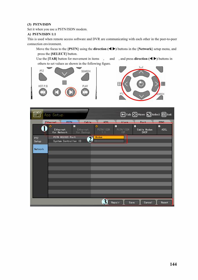
144
(3) PSTN/ISDN Set it when you use a PSTN/ISDN modem. A) PSTN/ISDN 1:1 This is used when remote access software and DVR are communicating with each other in the peer-to-peer connection environment.
� Move the focus to the {PSTN} using the direction ( ) buttons in the {Network} setup menu, and press the [SELECT] button.
� Use the [TAB] button for movement in items �, � and �, and press direction ( ) buttons in others to set values as shown in the following figure.

145
B) PSTN/ISDN ISP This is used when the communication environment is established through an ISP provider.
� Move the focus to the {PSTN} using the direction ( ) buttons in the {Network} setup menu,, and press the [SELECT] button.
� Use the [TAB] button or direction ( ) buttons for movement in items to set values as shown below.
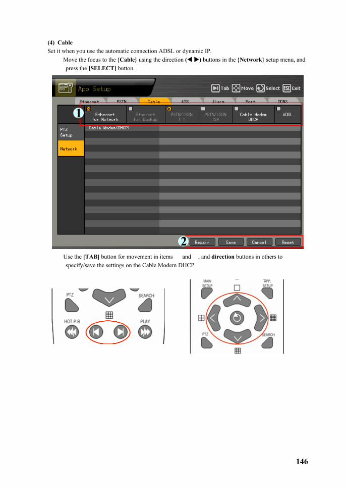
146
(4) Cable Set it when you use the automatic connection ADSL or dynamic IP.
� Move the focus to the {Cable} using the direction ( ) buttons in the {Network} setup menu, and press the [SELECT] button.
� Use the [TAB] button for movement in items � and �, and direction buttons in others to
specify/save the settings on the Cable Modem DHCP.

147
(5) ADSL Use it in the user authentication-type ADSL communication environment.
� Move the focus to the {ADSL} using the direction ( ) buttons in the {Network} setup menu, and press the [SELECT] button.
� Use the [TAB] button for movement in items �, �, and �, and direction ( ) buttons to
enter/save user ID and password.

148
(6) Alarm This setup is for a wired telephone or email alarm-out when an event occurs. To use this function, set the Call or Mail alarm output to On in the {Main setup} {Data setup}.
� Move the focus to the {Alarm} using the direction ( ) buttons in the {Network} setup menu, and press the [SELECT] button.
� Set the telephone number and transmission/reception mail using the [TAB] button for the item movements in �, �, and � and direction buttons for the others.

149
(7) Port This function is used to set the network ports. The default value is 2000 to 2007, and you can select a proper value depending on the network environment such as the firewall.
� Move the focus to the {Port} using the direction ( ) buttons in the {Network} setup menu, and press the [SELECT] button.
� Using the [TAB] button and direction ( ) buttons, set each port number.
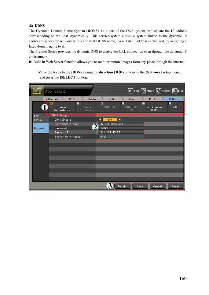
150
(8) DDNS The Dynamic Domain Name System (DDNS), as a part of the DNS system, can update the IP address corresponding to the host, dynamically. This service/system allows a system linked to the dynamic IP address to access the network with a constant DDNS name, even if its IP address is changed, by assigning a fixed domain name to it. The Premier Series provides the dynamic DNS to enable the URL connection even through the dynamic IP environment. Its Built-In Web Server function allows you to monitor remote images from any place through the internet.
� Move the focus to the {DDNS} using the direction ( ) buttons in the {Network} setup menu,, and press the [SELECT] button.

151
� Set the usability of DDNS function using the direction ( ) buttons, as shown in the following figure.
� Register the domain name registered to the DDNS server. Register a domain name you want to use by accessing the DDNS server, and enter a unique URL. For more information, please refer to the DDNS manual. Call 866-301-2288 for help with this step.
� Enter the DDNS access password that you set at the DDNS server.
� Enter the IP address of the DDNS server. The Default IP address of the DDNS server is 211.117.45.25.
� Set the default port of the DDNS server. The default port of the DDNS server is 9100.

152
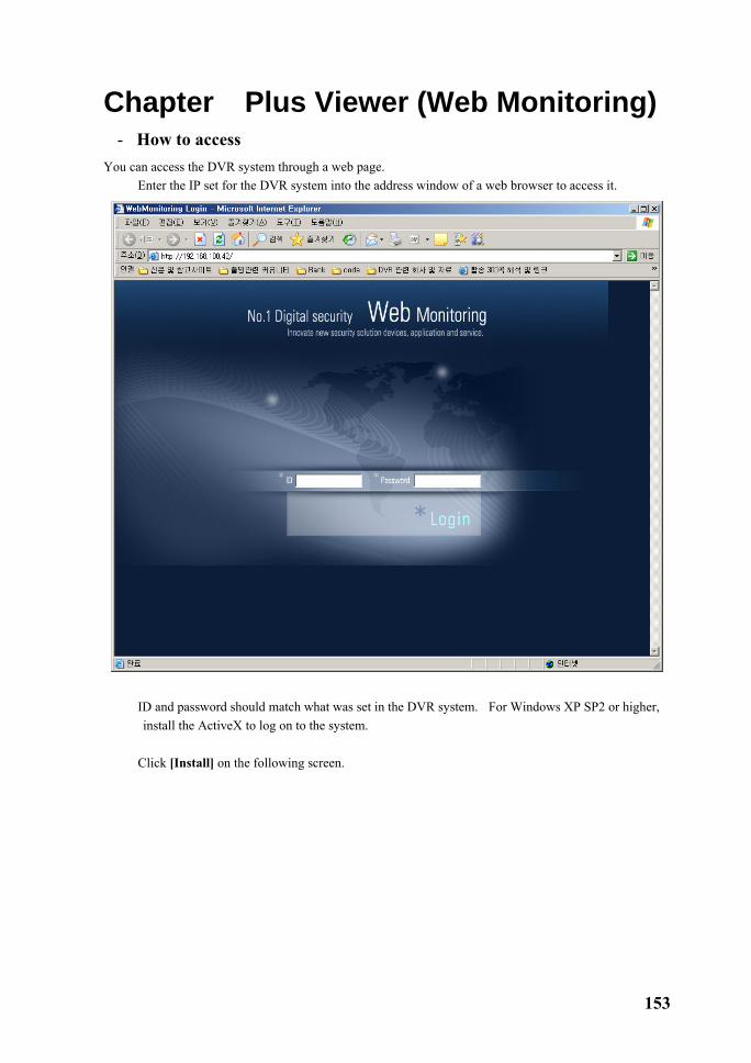
153
Chapter� Plus Viewer (Web Monitoring) �-�How to access You can access the DVR system through a web page.
� Enter the IP set for the DVR system into the address window of a web browser to access it.
� ID and password should match what was set in the DVR system. For Windows XP SP2 or higher, install the ActiveX to log on to the system.
� Click [Install] on the following screen.

154
� When the ActiveX has completely installed, you can use the Plus Viewer from the web browser.

155
�-�Description on basic functions � The following numbers indicate channels. Click one of them to see the full screen view of the
corresponding channel.
� This screen shows the full screen view of the 2nd channel.
� If you click the live screen, the channel is selected and the color of the frame boundary of the
channel is changed. (The following figure shows the screen corresponding to the 7th channel.)
� To see full screen view, double-click the channel as well.

156
�-�Audio � Click the Audio button to control the audio volume.
� After you have altered the volume, click the Close button on the right side of the screen to exit it.
�-�Color Adjust � You can control the display color by clicking the Color Adjust.
� After you have altered each setting, click the Close to save setting and close the screen.

157
�-�DVR Network Setting � You can see the current setting information for the DVR by clicking the DVR Network Setting.
� The following screen shows the Product Information.
1. Software version: 00 (Build Number) 2. Hardware version 3. Video type 4. HDD use information Total space Used space Free space Record start date Record end date 5. Network setup information 6. HDD overwriting On/Off
� If you click the Picture Setting, a window that allows you to control the resolution/quality/frame rate is displayed.

158
Picture Resolution Controls the resolution of images. The lower the resolution, the faster the network transmission speed is. (CIF > Field > Full) Picture Quality Controls the quality of images. The larger the number, the quality is lower and the network transmission speed is faster due to higher compression rate.
Enable Temporal Filter If there is a lot of noise in the images, it decreases unnecessary images and increases the network transmission speed by removing them.
Picture Frame Rate Controls the number of transmission frames of an image. Based on 30 frames approximately it is set as follows. High:30, Medium:15, Low:7.5
� If you click the Network Account, the window that shows the user information is displayed.
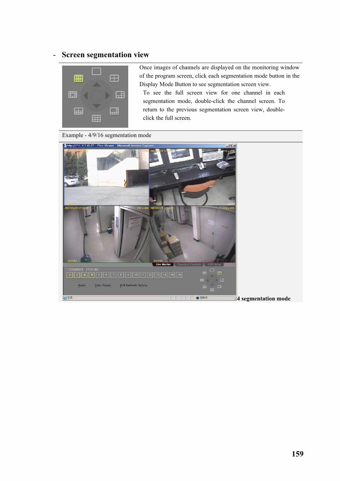
159
�-�Screen segmentation view
Once images of channels are displayed on the monitoring window of the program screen, click each segmentation mode button in the Display Mode Button to see segmentation screen view.
To see the full screen view for one channel in each segmentation mode, double-click the channel screen. To return to the previous segmentation screen view, double-click the full screen.
Example - 4/9/16 segmentation mode
4 segmentation mode

160
6 segmentation mode
8 segmentation mode

161
9 segmentation mode
10 segmentation mode

162
13 segmentation mode
�-�Search and Playback This function is used to search and play images recorded in the remote DVR in real time.
� Click the Search & Playback tab on the bottom of the display.

163
��-���-���Selecting a search method
� Search through - shows the recorded images as an hour/minute histogram.
� Search through - shows the recorded images as a file list.
��-���-���Search and playback
� Click or at the search window to select the search method.
� Select the corresponding date on the calendar. The days that include recorded images are separately displayed with a triangle.
� If you select the corresponding date, move the bar to the desired time and click , and it
goes to the next screen.
� After you move the bar to the desired minute, click to play the screen or click

164
to return to the previous screen.
� This shows the Playback screen.

165
��-���-���Playback control
� It is possible to control the screen segmentation and playback speed through the control on the bottom right side of the screen.
��-���-���Screen description
� A & V – lists all the recorded images. � Video – lists files that only include images. � Audio – lists files that only include sounds. � All -lists all the recorded images. � Motion – displays parts where a motion event occurs. � Sensor – displays parts where a sensor event occurs. � Audio – displays parts where a sound identification event occurs. � General images are displayed with a green bar, and parts where an event occurs are displayed with a
red bar.

166
�-�DVR Setup The remote DVR setup screen consists of Graphic User Interface (GUI) that is the same as the On Screen Display (DVR OSD) setup menu.
� If you click , the following screen is displayed.
� Change the system settings using the mouse on the DVR setup screen.
For more information on the system setup, please refer to Chapter 5. System setup.
� After you have finished the setup, click to complete it.

167
Chapter� Quick Viewer Once you backed up recorded data using a backup device at the DVR system, the recorded image data folder along with QuickViewer.exe and mwmp4dec.dll files are created in the corresponding folder. If you run the QuickViewer.exe, the Quick Viewer is started.

168
�-�File playback � If you click the [File] – [Open], the window where you can select a file you want to play is displayed.
� If you select the rms file of the channel you want to play, you are ready to play it.

169
�-�Button description
� Fast Backward Play – Fast backward play
� Backward Play – Normal backward play
� Frame by Backward – Backward search by frame
� Frame by Forward – Forward search by frame
� Forward Play – Forward play
� Fast Forward Play – Fast forward play
� Volume – Volume control
�-�Version information � To see the version information for the Quick Viewer, click the [Help] – [About].
170
Premier Series A/P/P/E/N/D/I/X
A/P/P/E/N/D/I/X .......................................................................................... 171
1 PTZ Camera protocol..............................................................................................172
2 Recommended HDD.................................................................................................172
3 Recommended USB2.0 device. .............................................................................173
Memory stick....................................................................................................................173 2.5’’ Portable USB HDD..................................................................................................173 CD-RW, DVD-RW ..........................................................................................................173 IEEE1394 device ..............................................................................................................173

171
1. PTZ camera protocol NO Vender Protocol name 1 CHOU COHU-3925 2 Kalatel KALATEL 3 Hitron FASTRAX2 4 Panasonic WVCS854, WV-CS850A, WV-CS854, WV-CW860 external 5 Dongyang DRX_500 6 Samsung SCC641 7 GSP CYBERSCAN_1 8 HONEYWELL HSDN251 9 PHILIPS PHILIPS 10 RIFATRON RIFATRON 11 VICON VICON 12 AMERICAN DYNAMICS SENSORMATIC 13 PELCO PELCO – D, PELCO - P 14 PROLINE PROLINE - UK 15 SAMSUNG TECHWIN SPD-1600 2. Recommended HDD NO Vender Model Capacity Buffer RPM
1 Western Digital WD WD1200 WD WD2500 WD WD2500
120GB 250GB 250GB
2M 2M 8M
7200 7200 7200
2 Segate
SEAGATE BARRACUDA 7200.9 ST3120213A SEAGATE BARRACUDA 7200.7 ST3160023A SEAGATE BARRACUDA 7200.7 ST3200822A SEAGATE BARRACUDA 7200.9 ST3250824A SEAGATE BARRACUDA 7200.8 ST3300831A
120GB 160GB 200GB 250GB 300GB
8M 8M 8M 8M 8M
7200 7200 7200 7200 7200
3 Samsung Samsung SP1203N/DOM Samsung SP2514N/OMD
120GB 250GB
2M 8M
7200 7200
4 HITHACHI HITHACHI Desk star HITHACHI Desk star HITHACHI Desk star
120GB 250GB 500GB
8M 8M 8M
7200 7200 7200
5 MAXTOR MAXTOR DIAMOND MAX 11 500GB 7200

172
3. Recommended USB2.0 device
USB2.0 device Media File system Memory Stick Flash Type FAT32 2.5’’ Portable USB HDD HDD Type FAT32 CD CD R, R/W ISO9660 DVD DVD +R, +R/W ISO9660
Memory stick No. Vender Model Capacity 1 Transcend Ultra Speed JetFlash 256MB 2 FM semiconductor MemoRive USB2.0 256MB 3 LG Xtick USB Drive 256MB 4 AL Tech ANYDRIVE mini USB 256MB 5 Kingston DataTraveler USB FLASH DRIVE 256MB 6 Saroe Tech FLEX FD-03U1 128MB 8 Scandrive Cruzer Mini 128M 10 Samsung PLEOMAX 128MB 11 Sony Micro Vault 128M
2.5’’ Portable USB HDD No. Vender Model Capacity 1 IT Mall neo Q Plus USB 2.0 20GB 2 USB Net Co. Ltd Anypak USB 2.0 20GB 20GB
CD-RW, DVD-RW Vender Model SONY DRX-810UL
Plextor PX-716UF SAMSUNG SE-W164
IEEE1394 device IEEE1394 device Media File system
2.5’’ Portable USB HDD HDD Type FAT32 CD CD R, R/W ISO9660 DVD DVD +R, +R/W ISO9660