FBD - Richmond Community Collegeengineering.richmondcc.edu/Courses/ATR...
172
FBD FBD FBD FBD This chapter contains the following information: • Bit Bit Bit Bit logic logic logic logic operations operations operations operations (S7-1200, (S7-1200, (S7-1200, (S7-1200, S7-1500) S7-1500) S7-1500) S7-1500) • Timer Timer Timer Timer operations operations operations operations (S7-1200, (S7-1200, (S7-1200, (S7-1200, S7-1500) S7-1500) S7-1500) S7-1500) • Counter Counter Counter Counter operations operations operations operations (S7-1200, (S7-1200, (S7-1200, (S7-1200, S7-1500) S7-1500) S7-1500) S7-1500) • Comparator Comparator Comparator Comparator operations operations operations operations (S7-1200, (S7-1200, (S7-1200, (S7-1200, S7-1500) S7-1500) S7-1500) S7-1500) • Math Math Math Math functions functions functions functions (S7-1200, (S7-1200, (S7-1200, (S7-1200, S7-1500) S7-1500) S7-1500) S7-1500) • Move Move Move Move operations operations operations operations (S7-1200, (S7-1200, (S7-1200, (S7-1200, S7-1500) S7-1500) S7-1500) S7-1500) • Conversion Conversion Conversion Conversion operations operations operations operations (S7-1200, (S7-1200, (S7-1200, (S7-1200, S7-1500) S7-1500) S7-1500) S7-1500) • Program Program Program Program control control control control operations operations operations operations (S7-1200, (S7-1200, (S7-1200, (S7-1200, S7-1500) S7-1500) S7-1500) S7-1500) • Word Word Word Word logic logic logic logic operations operations operations operations (S7-1200, (S7-1200, (S7-1200, (S7-1200, S7-1500) S7-1500) S7-1500) S7-1500) • Shift Shift Shift Shift and and and and rotate rotate rotate rotate (S7-1200, (S7-1200, (S7-1200, (S7-1200, S7-1500) S7-1500) S7-1500) S7-1500) • Additional Additional Additional Additional instructions instructions instructions instructions (S7-1500) (S7-1500) (S7-1500) (S7-1500) FBD (S7-1200, S7-1500) - 1 -
Transcript of FBD - Richmond Community Collegeengineering.richmondcc.edu/Courses/ATR...
FBDFBDFBDFBD
This chapter contains the following information:
• Bit Bit Bit Bit logic logic logic logic operations operations operations operations (S7-1200, (S7-1200, (S7-1200, (S7-1200, S7-1500)S7-1500)S7-1500)S7-1500)
• Timer Timer Timer Timer operations operations operations operations (S7-1200, (S7-1200, (S7-1200, (S7-1200, S7-1500)S7-1500)S7-1500)S7-1500)
• Counter Counter Counter Counter operations operations operations operations (S7-1200, (S7-1200, (S7-1200, (S7-1200, S7-1500)S7-1500)S7-1500)S7-1500)
• Comparator Comparator Comparator Comparator operations operations operations operations (S7-1200, (S7-1200, (S7-1200, (S7-1200, S7-1500)S7-1500)S7-1500)S7-1500)
• Math Math Math Math functions functions functions functions (S7-1200, (S7-1200, (S7-1200, (S7-1200, S7-1500)S7-1500)S7-1500)S7-1500)
• Move Move Move Move operations operations operations operations (S7-1200, (S7-1200, (S7-1200, (S7-1200, S7-1500)S7-1500)S7-1500)S7-1500)
• Conversion Conversion Conversion Conversion operations operations operations operations (S7-1200, (S7-1200, (S7-1200, (S7-1200, S7-1500)S7-1500)S7-1500)S7-1500)
• Program Program Program Program control control control control operations operations operations operations (S7-1200, (S7-1200, (S7-1200, (S7-1200, S7-1500)S7-1500)S7-1500)S7-1500)
• Word Word Word Word logic logic logic logic operations operations operations operations (S7-1200, (S7-1200, (S7-1200, (S7-1200, S7-1500)S7-1500)S7-1500)S7-1500)
• Shift Shift Shift Shift and and and and rotate rotate rotate rotate (S7-1200, (S7-1200, (S7-1200, (S7-1200, S7-1500)S7-1500)S7-1500)S7-1500)
• Additional Additional Additional Additional instructions instructions instructions instructions (S7-1500)(S7-1500)(S7-1500)(S7-1500)
FBD (S7-1200, S7-1500)
- 1 -

Bit Bit Bit Bit logic logic logic logic operationsoperationsoperationsoperations
This chapter contains the following information:
• &: &: &: &: AND AND AND AND logic logic logic logic operation operation operation operation (S7-1200, (S7-1200, (S7-1200, (S7-1200, S7-1500)S7-1500)S7-1500)S7-1500)
• AND AND AND AND truth truth truth truth table table table table (S7-1200, (S7-1200, (S7-1200, (S7-1200, S7-1500)S7-1500)S7-1500)S7-1500)
• >=1: >=1: >=1: >=1: OR OR OR OR logic logic logic logic operation operation operation operation (S7-1200, (S7-1200, (S7-1200, (S7-1200, S7-1500)S7-1500)S7-1500)S7-1500)
• OR OR OR OR truth truth truth truth table table table table (S7-1200, (S7-1200, (S7-1200, (S7-1200, S7-1500)S7-1500)S7-1500)S7-1500)
• X: X: X: X: EXCLUSIVE EXCLUSIVE EXCLUSIVE EXCLUSIVE OR OR OR OR logic logic logic logic operation operation operation operation (S7-1200, (S7-1200, (S7-1200, (S7-1200, S7-1500)S7-1500)S7-1500)S7-1500)
• EXCLUSIVE EXCLUSIVE EXCLUSIVE EXCLUSIVE OR OR OR OR truth truth truth truth table table table table (S7-1200, (S7-1200, (S7-1200, (S7-1200, S7-1500)S7-1500)S7-1500)S7-1500)
• Insert Insert Insert Insert input input input input (S7-1200, (S7-1200, (S7-1200, (S7-1200, S7-1500)S7-1500)S7-1500)S7-1500)
• Invert Invert Invert Invert RLO RLO RLO RLO (S7-1200, (S7-1200, (S7-1200, (S7-1200, S7-1500)S7-1500)S7-1500)S7-1500)
• =: =: =: =: Assignment Assignment Assignment Assignment (S7-1200, (S7-1200, (S7-1200, (S7-1200, S7-1500)S7-1500)S7-1500)S7-1500)
• /=: /=: /=: /=: Negate Negate Negate Negate assignment assignment assignment assignment (S7-1200, (S7-1200, (S7-1200, (S7-1200, S7-1500)S7-1500)S7-1500)S7-1500)
• R: R: R: R: Reset Reset Reset Reset output output output output (S7-1200, (S7-1200, (S7-1200, (S7-1200, S7-1500)S7-1500)S7-1500)S7-1500)
• S: S: S: S: Set Set Set Set output output output output (S7-1200, (S7-1200, (S7-1200, (S7-1200, S7-1500)S7-1500)S7-1500)S7-1500)
• SET_BF: SET_BF: SET_BF: SET_BF: Set Set Set Set bit bit bit bit field field field field (S7-1200, (S7-1200, (S7-1200, (S7-1200, S7-1500)S7-1500)S7-1500)S7-1500)
• RESET_BF: RESET_BF: RESET_BF: RESET_BF: Reset Reset Reset Reset bit bit bit bit field field field field (S7-1200, (S7-1200, (S7-1200, (S7-1200, S7-1500)S7-1500)S7-1500)S7-1500)
• SR: SR: SR: SR: Set/reset Set/reset Set/reset Set/reset flip-flop flip-flop flip-flop flip-flop (S7-1200, (S7-1200, (S7-1200, (S7-1200, S7-1500)S7-1500)S7-1500)S7-1500)
• RS: RS: RS: RS: Reset/set Reset/set Reset/set Reset/set flip-flop flip-flop flip-flop flip-flop (S7-1200, (S7-1200, (S7-1200, (S7-1200, S7-1500)S7-1500)S7-1500)S7-1500)
• P: P: P: P: Scan Scan Scan Scan operand operand operand operand for for for for positive positive positive positive signal signal signal signal edge edge edge edge (S7-1200, (S7-1200, (S7-1200, (S7-1200, S7-1500)S7-1500)S7-1500)S7-1500)
• N: N: N: N: Scan Scan Scan Scan operand operand operand operand for for for for negative negative negative negative signal signal signal signal edge edge edge edge (S7-1200, (S7-1200, (S7-1200, (S7-1200, S7-1500)S7-1500)S7-1500)S7-1500)
• P=: P=: P=: P=: Set Set Set Set operand operand operand operand on on on on positive positive positive positive signal signal signal signal edge edge edge edge (S7-1200, (S7-1200, (S7-1200, (S7-1200, S7-1500)S7-1500)S7-1500)S7-1500)
• N=: N=: N=: N=: Set Set Set Set operand operand operand operand on on on on negative negative negative negative signal signal signal signal edge edge edge edge (S7-1200, (S7-1200, (S7-1200, (S7-1200, S7-1500)S7-1500)S7-1500)S7-1500)
• P_TRIG: P_TRIG: P_TRIG: P_TRIG: Scan Scan Scan Scan RLO RLO RLO RLO for for for for positive positive positive positive signal signal signal signal edge edge edge edge (S7-1200, (S7-1200, (S7-1200, (S7-1200, S7-1500)S7-1500)S7-1500)S7-1500)
• N_TRIG: N_TRIG: N_TRIG: N_TRIG: Scan Scan Scan Scan RLO RLO RLO RLO for for for for negative negative negative negative signal signal signal signal edge edge edge edge (S7-1200, (S7-1200, (S7-1200, (S7-1200, S7-1500)S7-1500)S7-1500)S7-1500)
• R_TRIG: R_TRIG: R_TRIG: R_TRIG: Set Set Set Set tag tag tag tag on on on on positive positive positive positive signal signal signal signal edge edge edge edge (S7-1200, (S7-1200, (S7-1200, (S7-1200, S7-1500)S7-1500)S7-1500)S7-1500)
• F_TRIG: F_TRIG: F_TRIG: F_TRIG: Set Set Set Set tag tag tag tag on on on on negative negative negative negative signal signal signal signal edge edge edge edge (S7-1200, (S7-1200, (S7-1200, (S7-1200, S7-1500)S7-1500)S7-1500)S7-1500)
Bit logic operations (S7-1200, S7-1500)
- 2 -
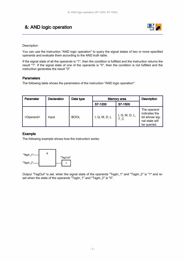
&: &: &: &: AND AND AND AND logic logic logic logic operationoperationoperationoperation
Description
You can use the instruction "AND logic operation" to query the signal states of two or more specifiedoperands and evaluate them according to the AND truth table.
If the signal state of all the operands is "1", then the condition is fulfilled and the instruction returns theresult "1". If the signal state of one of the operands is "0", then the condition is not fulfilled and theinstruction generates the result "0".
ParametersParametersParametersParametersThe following table shows the parameters of the instruction "AND logic operation":
ParameterParameterParameterParameter DeclarationDeclarationDeclarationDeclaration Data Data Data Data typetypetypetype Memory Memory Memory Memory areaareaareaarea DescriptionDescriptionDescriptionDescriptionS7-1200S7-1200S7-1200S7-1200 S7-1500S7-1500S7-1500S7-1500
<Operand> Input BOOL I, Q, M, D, L I, Q, M, D, L,T, C
The operandindicates thebit whose sig‐nal state willbe queried.
ExampleExampleExampleExampleThe following example shows how the instruction works:
Output "TagOut" is set, when the signal state of the operands "TagIn_1" and "TagIn_2" is "1" and re‐set when the state of the operands "TagIn_1" and "TagIn_2" is "0".
&: AND logic operation (S7-1200, S7-1500)
- 3 -

AND AND AND AND truth truth truth truth tabletabletabletable
Results of the logic operation
The following table shows the results that arise from the AND logic operation of two operands:
Signal Signal Signal Signal state state state state of of of of the the the the first first first first operandoperandoperandoperand Signal Signal Signal Signal state state state state of of of of the the the the second second second second oper‐oper‐oper‐oper‐andandandand
Result Result Result Result of of of of the the the the logic logic logic logic operationoperationoperationoperation
1 1 10 1 01 0 00 0 0
AND truth table (S7-1200, S7-1500)
- 4 -

>=1: >=1: >=1: >=1: OR OR OR OR logic logic logic logic operationoperationoperationoperation
Description
You can use the instruction "OR logic operation" to query the signal states of two or more specifiedoperands and evaluate them according to the OR truth table.
If the signal state of one of the operands is "1", then the condition is fulfilled and the instruction returnsthe result "1". If the signal state of all the operands is "0", then the condition is not fulfilled and theinstruction generates the result "0".
ParametersParametersParametersParametersThe following table shows the parameters of the instruction "OR logic operation":
ParameterParameterParameterParameter DeclarationDeclarationDeclarationDeclaration Data Data Data Data typetypetypetype Memory Memory Memory Memory areaareaareaarea DescriptionDescriptionDescriptionDescriptionS7-1200S7-1200S7-1200S7-1200 S7-1500S7-1500S7-1500S7-1500
<Operand> Input BOOL I, Q, M, D, L I, Q, M, D, L,T, C
The operandindicates thebit whose sig‐nal state willbe queried.
ExampleExampleExampleExampleThe following example shows how the instruction works:
Output "TagOut" is set, when the signal state of the operands "TagIn_1" or "TagIn_2" is "1".
>=1: OR logic operation (S7-1200, S7-1500)
- 5 -

OR OR OR OR truth truth truth truth tabletabletabletable
Results of the logic operation
The following table shows the results that arise from the OR logic operation of two operands:
Signal Signal Signal Signal state state state state of of of of the the the the first first first first operandoperandoperandoperand Signal Signal Signal Signal state state state state of of of of the the the the second second second second oper‐oper‐oper‐oper‐andandandand
Result Result Result Result of of of of the the the the logic logic logic logic operationoperationoperationoperation
1 0 10 1 11 1 10 0 0
OR truth table (S7-1200, S7-1500)
- 6 -

X: X: X: X: EXCLUSIVE EXCLUSIVE EXCLUSIVE EXCLUSIVE OR OR OR OR logic logic logic logic operationoperationoperationoperation
Description
You can use the instruction "EXCLUSIVE OR logic operation" to query the result of a signal statequery according to the EXCLUSIVE OR truth table.
With an instruction "EXCLUSIVE OR logic operation", the signal state is "1" when the signal state ofone of the two specified operands is "1". When more than two operands are queried, the commonRLO is "1" if an odd number of the queried operands returns the result "1".
ParametersParametersParametersParametersThe following table shows the parameters of the instruction "EXCLUSIVE OR logic operation":
ParameterParameterParameterParameter DeclarationDeclarationDeclarationDeclaration Data Data Data Data typetypetypetype Memory Memory Memory Memory areaareaareaarea DescriptionDescriptionDescriptionDescriptionS7-1200S7-1200S7-1200S7-1200 S7-1500S7-1500S7-1500S7-1500
<Operand> Input BOOL I, Q, M, D, L I, Q, M, D, L,T, C
The operandindicates thebit whose sig‐nal state willbe queried.
ExampleExampleExampleExampleThe following example shows how the instruction works:
Output "TagOut" is set when the signal state of the operands "TagIn_1" and "TagIn_2" is "1". Whenboth operands return the signal state "1" or "0", the output "TagOut" is reset.
X: EXCLUSIVE OR logic operation (S7-1200, S7-1500)
- 7 -
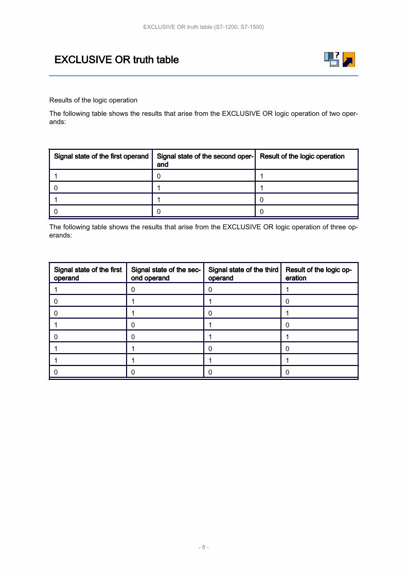
EXCLUSIVE EXCLUSIVE EXCLUSIVE EXCLUSIVE OR OR OR OR truth truth truth truth tabletabletabletable
Results of the logic operation
The following table shows the results that arise from the EXCLUSIVE OR logic operation of two oper‐ands:
Signal Signal Signal Signal state state state state of of of of the the the the first first first first operandoperandoperandoperand Signal Signal Signal Signal state state state state of of of of the the the the second second second second oper‐oper‐oper‐oper‐andandandand
Result Result Result Result of of of of the the the the logic logic logic logic operationoperationoperationoperation
1 0 10 1 11 1 00 0 0
The following table shows the results that arise from the EXCLUSIVE OR logic operation of three op‐erands:
Signal Signal Signal Signal state state state state of of of of the the the the firstfirstfirstfirstoperandoperandoperandoperand
Signal Signal Signal Signal state state state state of of of of the the the the sec‐sec‐sec‐sec‐ond ond ond ond operandoperandoperandoperand
Signal Signal Signal Signal state state state state of of of of the the the the thirdthirdthirdthirdoperandoperandoperandoperand
Result Result Result Result of of of of the the the the logic logic logic logic op‐op‐op‐op‐erationerationerationeration
1 0 0 10 1 1 00 1 0 11 0 1 00 0 1 11 1 0 01 1 1 10 0 0 0
EXCLUSIVE OR truth table (S7-1200, S7-1500)
- 8 -
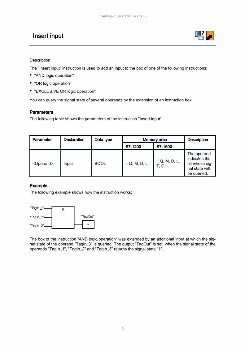
Insert Insert Insert Insert inputinputinputinput
Description
The "Insert input" instruction is used to add an input to the box of one of the following instructions:
• "AND logic operation"
• "OR logic operation"
• "EXCLUSIVE OR logic operation"
You can query the signal state of several operands by the extension of an instruction box.
ParametersParametersParametersParametersThe following table shows the parameters of the instruction "Insert input":
ParameterParameterParameterParameter DeclarationDeclarationDeclarationDeclaration Data Data Data Data typetypetypetype Memory Memory Memory Memory areaareaareaarea DescriptionDescriptionDescriptionDescriptionS7-1200S7-1200S7-1200S7-1200 S7-1500S7-1500S7-1500S7-1500
<Operand> Input BOOL I, Q, M, D, L I, Q, M, D, L,T, C
The operandindicates thebit whose sig‐nal state willbe queried.
ExampleExampleExampleExampleThe following example shows how the instruction works:
The box of the instruction "AND logic operation" was extended by an additional input at which the sig‐nal state of the operand "TagIn_3" is queried. The output "TagOut" is set, when the signal state of theoperands "TagIn_1", "TagIn_2" and "TagIn_3" returns the signal state "1".
Insert input (S7-1200, S7-1500)
- 9 -

Invert Invert Invert Invert RLORLORLORLO
Description
You use the "Invert RLO" instruction to invert the signal state of the result of logic operation (RLO).
ExampleExampleExampleExampleThe following example shows how the instruction works:
The output "TagOut" is set when the following conditions are fulfilled:
• The input "TagIn_1" and/or "TagIn_2" has signal state "0".
• The input "TagIn_3" and/or "TagIn_4" has signal state "0" or the input "TagIn_5" has signal state"1".
Invert RLO (S7-1200, S7-1500)
- 10 -
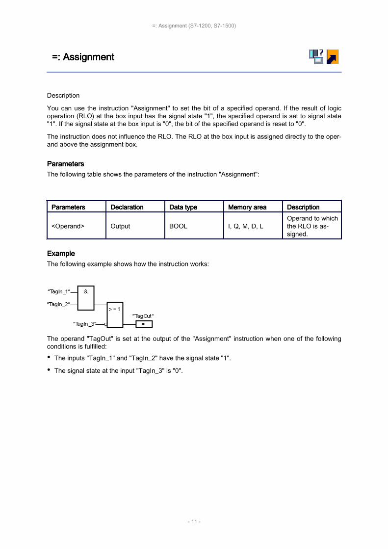
=: =: =: =: AssignmentAssignmentAssignmentAssignment
Description
You can use the instruction "Assignment" to set the bit of a specified operand. If the result of logicoperation (RLO) at the box input has the signal state "1", the specified operand is set to signal state"1". If the signal state at the box input is "0", the bit of the specified operand is reset to "0".
The instruction does not influence the RLO. The RLO at the box input is assigned directly to the oper‐and above the assignment box.
ParametersParametersParametersParametersThe following table shows the parameters of the instruction "Assignment":
ParametersParametersParametersParameters DeclarationDeclarationDeclarationDeclaration Data Data Data Data typetypetypetype Memory Memory Memory Memory areaareaareaarea DescriptionDescriptionDescriptionDescription
<Operand> Output BOOL I, Q, M, D, LOperand to whichthe RLO is as‐signed.
ExampleExampleExampleExampleThe following example shows how the instruction works:
The operand "TagOut" is set at the output of the "Assignment" instruction when one of the followingconditions is fulfilled:
• The inputs "TagIn_1" and "TagIn_2" have the signal state "1".
• The signal state at the input "TagIn_3" is "0".
=: Assignment (S7-1200, S7-1500)
- 11 -

/=: /=: /=: /=: Negate Negate Negate Negate assignmentassignmentassignmentassignment
Description
The instruction "Negate assignment" inverts the result of logic operation (RLO) and assigns this to theoperand above the box. If the RLO at the input of the box is "1", the binary operand is reset. If theRLO at the input of the box is "0", the operand is set to signal state "1".
ParametersParametersParametersParametersThe following table shows the parameters of the instruction "Negate assignment":
ParametersParametersParametersParameters DeclarationDeclarationDeclarationDeclaration Data Data Data Data typetypetypetype Memory Memory Memory Memory areaareaareaarea DescriptionDescriptionDescriptionDescription
<Operand> Output BOOL I, Q, M, D, LOperand to whichthe negated RLOis assigned.
ExampleExampleExampleExampleThe following example shows how the instruction works:
The operand "TagOut" is reset when the following conditions are fulfilled:
• The operand "TagIn_1" or "TagIn_2" has the signal state "1".
• The operand "TagIn_3" has the signal state "0".
/=: Negate assignment (S7-1200, S7-1500)
- 12 -
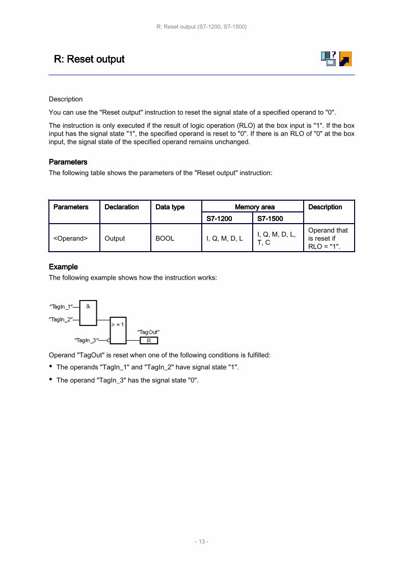
R: R: R: R: Reset Reset Reset Reset outputoutputoutputoutput
Description
You can use the "Reset output" instruction to reset the signal state of a specified operand to "0".
The instruction is only executed if the result of logic operation (RLO) at the box input is "1". If the boxinput has the signal state "1", the specified operand is reset to "0". If there is an RLO of "0" at the boxinput, the signal state of the specified operand remains unchanged.
ParametersParametersParametersParametersThe following table shows the parameters of the "Reset output" instruction:
ParametersParametersParametersParameters DeclarationDeclarationDeclarationDeclaration Data Data Data Data typetypetypetype Memory Memory Memory Memory areaareaareaarea DescriptionDescriptionDescriptionDescriptionS7-1200S7-1200S7-1200S7-1200 S7-1500S7-1500S7-1500S7-1500
<Operand> Output BOOL I, Q, M, D, L I, Q, M, D, L,T, C
Operand thatis reset ifRLO = "1".
ExampleExampleExampleExampleThe following example shows how the instruction works:
Operand "TagOut" is reset when one of the following conditions is fulfilled:
• The operands "TagIn_1" and "TagIn_2" have signal state "1".
• The operand "TagIn_3" has the signal state "0".
R: Reset output (S7-1200, S7-1500)
- 13 -
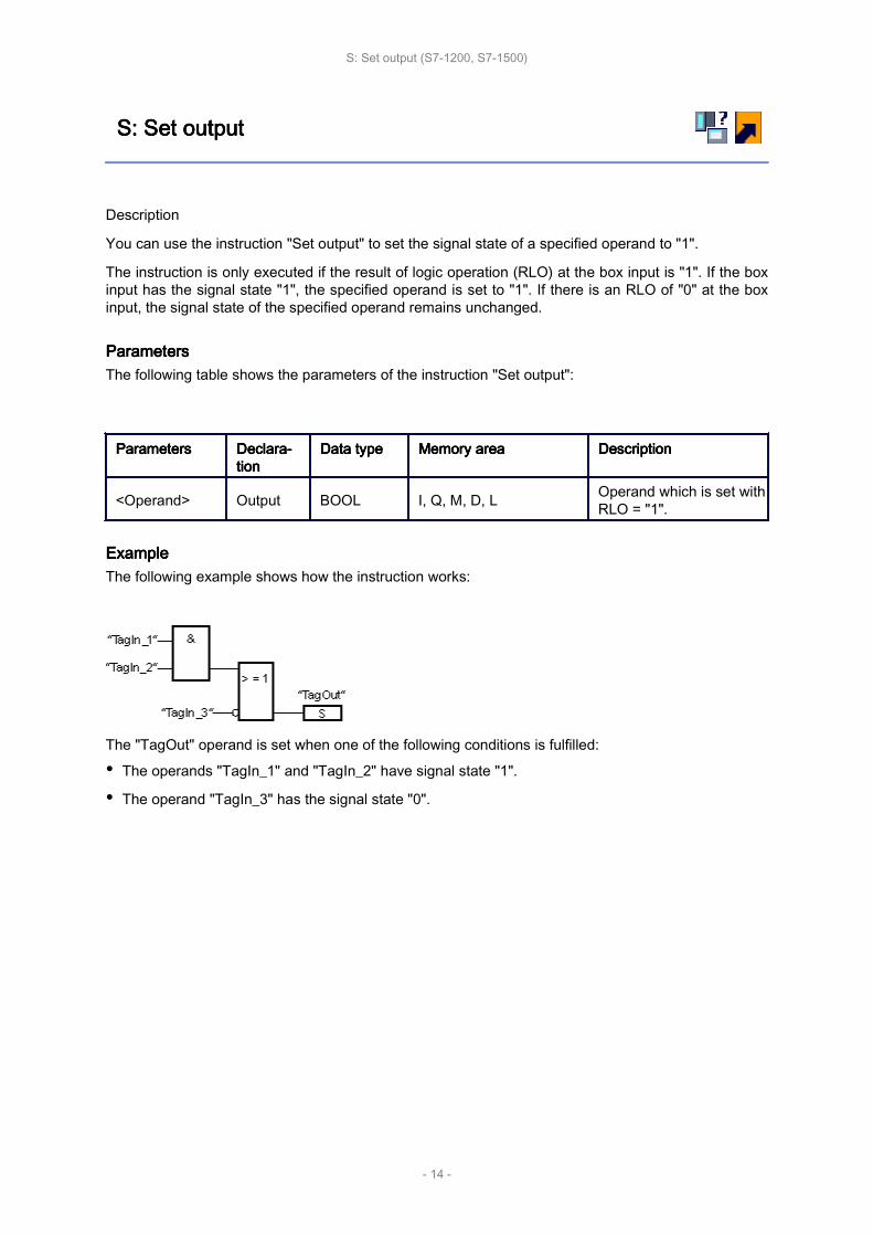
S: S: S: S: Set Set Set Set outputoutputoutputoutput
Description
You can use the instruction "Set output" to set the signal state of a specified operand to "1".
The instruction is only executed if the result of logic operation (RLO) at the box input is "1". If the boxinput has the signal state "1", the specified operand is set to "1". If there is an RLO of "0" at the boxinput, the signal state of the specified operand remains unchanged.
ParametersParametersParametersParametersThe following table shows the parameters of the instruction "Set output":
ParametersParametersParametersParameters Declara‐Declara‐Declara‐Declara‐tiontiontiontion
Data Data Data Data typetypetypetype Memory Memory Memory Memory areaareaareaarea DescriptionDescriptionDescriptionDescription
<Operand> Output BOOL I, Q, M, D, L Operand which is set withRLO = "1".
ExampleExampleExampleExampleThe following example shows how the instruction works:
The "TagOut" operand is set when one of the following conditions is fulfilled:
• The operands "TagIn_1" and "TagIn_2" have signal state "1".
• The operand "TagIn_3" has the signal state "0".
S: Set output (S7-1200, S7-1500)
- 14 -

SET_BF: SET_BF: SET_BF: SET_BF: Set Set Set Set bit bit bit bit fieldfieldfieldfield
Description
You can use the instruction "Set bit field" to set multiple bits starting from a certain address.
You can use the input N to define the number of bits to be set. The address of the first bit to be set isdefined by (<Operand>). If the value of the N input is greater than the number of bits in a selectedbyte, the bits of the next byte are set. The bits remain set until they are explicitly reset, for example,by another instruction.
ParametersParametersParametersParametersThe following table shows the parameters of the instruction "Set bit field":
ParametersParametersParametersParameters DeclarationDeclarationDeclarationDeclaration Data Data Data Data typetypetypetype Memory Memory Memory Memory areaareaareaarea DescriptionDescriptionDescriptionDescriptionS7-1200S7-1200S7-1200S7-1200 S7-1500S7-1500S7-1500S7-1500
EN Input BOOL I, Q, M, D, L I, Q, M, D, L, T,C Enable input
N Input UINT Constant Constant Number of bitsto be set
<Operand> Output BOOL
I, Q, M
In the caseof a DB oran IDB, anelement ofan AR‐RAY[..] ofBOOL
I, Q, M
In the case of aDB or an IDB,an element ofan ARRAY[..]of BOOL
Pointer to thefirst bit to beset.
ExampleExampleExampleExampleThe following example shows how the instruction works:
If the operands "TagIn_1" and "TagIn_2" have the signal state "1", 5 bits are set starting at the ad‐dress of the operand "MyDB".MyBoolArray[4].
SET_BF: Set bit field (S7-1200, S7-1500)
- 15 -

RESET_BF: RESET_BF: RESET_BF: RESET_BF: Reset Reset Reset Reset bit bit bit bit fieldfieldfieldfield
Description
You can use the instruction "Reset bit field" to reset several bits starting from a certain address.
You can use the value of the N input to define the number of bits to be reset. The address of the firstbit to be reset is defined by (<Operand>). If the value of the input N is greater than the number of bitsin a selected byte, the bits of the next byte are reset. The bits remain reset until they are explicitly set,for example, by another instruction.
ParametersParametersParametersParametersThe following table shows the parameters of the instruction "Reset bit field":
ParametersParametersParametersParameters DeclarationDeclarationDeclarationDeclaration Data Data Data Data typetypetypetype Memory Memory Memory Memory areaareaareaarea DescriptionDescriptionDescriptionDescriptionS7-1200S7-1200S7-1200S7-1200 S7-1500S7-1500S7-1500S7-1500
EN Input BOOL I, Q, M, D, L I, Q, M, D, L, T,C Enable input
N Input UINT Constant Constant Number of bitsto be reset.
<Operand> Output BOOL
I, Q, M
In the caseof a DB oran IDB, anelement ofan AR‐RAY[..] ofBOOL
I, Q, M
In the case of aDB or an IDB,an element ofan ARRAY[..]of BOOL
Pointer to thefirst bit to be re‐set.
ExampleExampleExampleExampleThe following example shows how the instruction works:
If the operands "TagIn_1" and "TagIn_2" have the signal state "1", 5 bits are reset starting at the ad‐dress of the operand "MyDB".MyBoolArray[4].
RESET_BF: Reset bit field (S7-1200, S7-1500)
- 16 -

SR: SR: SR: SR: Set/reset Set/reset Set/reset Set/reset flip-flopflip-flopflip-flopflip-flop
Description
You can use the instruction "Set/reset flip-flop" to set or reset the bit of a specified operand based onthe signal state of the inputs S and R1. If the signal state is "1" at input S and "0" at input R1, thespecified operand is set to "1". If the signal state is "0" at input S and "1" at input R1, the specifiedoperand will be reset to "0".
Input R1 takes priority over input S. When the signal state is "1" on both inputs S and R1, the signalstate of the specified operand is reset to "0".
The instruction is not executed if the signal state at the two inputs S and R1 is "0". The signal state ofthe operand then remains unchanged.
The current signal state of the operand is transferred to output Q and can be queried there.
ParametersParametersParametersParametersThe following table shows the parameters of the instruction "Set/reset flip-flop":
ParameterParameterParameterParameter DeclarationDeclarationDeclarationDeclaration Data Data Data Data typetypetypetype Memory Memory Memory Memory areaareaareaarea DescriptionDescriptionDescriptionDescriptionS7-1200S7-1200S7-1200S7-1200 S7-1500S7-1500S7-1500S7-1500
S Input BOOL I, Q, M, D, L I, Q, M, D, L,T, C Enable setting
R1 Input BOOL I, Q, M, D, L I, Q, M, D, L,T, C
Enable reset‐ting
<Operand> InOut BOOL I, Q, M, D, L I, Q, M, D, L Operand thatis set or reset
Q Output BOOL I, Q, M, D, L I, Q, M, D, L Signal state ofthe operand
ExampleExampleExampleExampleThe following example shows how the instruction works:
The operands "TagSR" and "TagOut" are set when the following conditions are fulfilled:
• The operand "TagIn_1" has the signal state "1".
• The operand "TagIn_2" has the signal state "0".
The operands "TagSR" and "TagOut" are reset when one of the following conditions is fulfilled:
SR: Set/reset flip-flop (S7-1200, S7-1500)
- 17 -

• The operand "TagIn_1" has signal state "0" and the operand "TagIn_2" has signal state "1".
• The operands "TagIn_1" and "TagIn_2" have signal state "1".
SR: Set/reset flip-flop (S7-1200, S7-1500)
- 18 -

RS: RS: RS: RS: Reset/set Reset/set Reset/set Reset/set flip-flopflip-flopflip-flopflip-flop
Description
You can use the instruction "Reset/set flip-flop" to reset or set the bit of a specified operand based onthe signal state of the inputs R and S1. If the signal state is "1" at input R and "0" at input S1, thespecified operand will be reset to "0". If the signal state is "0" at input R and "1" at input S1, the speci‐fied operand is set to "1".
Input S1 takes priority over input R. When the signal state is "1" at both inputs R and S1, the signalstate of the specified operand is set to "1".
The instruction is not executed if the signal state at the two inputs R and S1 is "0". The signal state ofthe operand then remains unchanged.
The current signal state of the operand is transferred to output Q and can be queried there.
ParametersParametersParametersParametersThe following table shows the parameters of the instruction "Reset/set flip-flop":
ParameterParameterParameterParameter DeclarationDeclarationDeclarationDeclaration Data Data Data Data typetypetypetype Memory Memory Memory Memory areaareaareaarea DescriptionDescriptionDescriptionDescriptionS7-1200S7-1200S7-1200S7-1200 S7-1500S7-1500S7-1500S7-1500
R Input BOOL I, Q, M, D, L I, Q, M, D, L,T, C
Enable reset‐ting
S1 Input BOOL I, Q, M, D, L I, Q, M, D, L,T, C Enable setting
<Operand> InOut BOOL I, Q, M, D, L I, Q, M, D, L Operand thatis reset or set.
Q Output BOOL I, Q, M, D, L I, Q, M, D, L Signal state ofthe operand
ExampleExampleExampleExampleThe following example shows how the instruction works:
The operands "TagRS" and "TagOut" are reset when the following conditions are fulfilled:
• The operand "TagIn_1" has the signal state "1".
• The operand "TagIn_2" has the signal state "0".
The operands "TagRS" and "TagOut" are set when the following conditions are fulfilled:
RS: Reset/set flip-flop (S7-1200, S7-1500)
- 19 -

• The operand "TagIn_1" has signal state "0" and the operand "TagIn_2" has signal state "1".
• The operands "TagIn_1" and "TagIn_2" have signal state "1".
RS: Reset/set flip-flop (S7-1200, S7-1500)
- 20 -

Timer Timer Timer Timer operationsoperationsoperationsoperations
This chapter contains the following information:
• IEC IEC IEC IEC Timers Timers Timers Timers (S7-1200, (S7-1200, (S7-1200, (S7-1200, S7-1500)S7-1500)S7-1500)S7-1500)
• SIMATIC SIMATIC SIMATIC SIMATIC Timers Timers Timers Timers (S7-1500)(S7-1500)(S7-1500)(S7-1500)
Timer operations (S7-1200, S7-1500)
- 21 -

IEC IEC IEC IEC TimersTimersTimersTimers
This chapter contains the following information:
• TP: TP: TP: TP: Generate Generate Generate Generate pulse pulse pulse pulse (S7-1200, (S7-1200, (S7-1200, (S7-1200, S7-1500)S7-1500)S7-1500)S7-1500)
• TON: TON: TON: TON: Generate Generate Generate Generate on-delay on-delay on-delay on-delay (S7-1200, (S7-1200, (S7-1200, (S7-1200, S7-1500)S7-1500)S7-1500)S7-1500)
• TOF: TOF: TOF: TOF: Generate Generate Generate Generate off-delay off-delay off-delay off-delay (S7-1200, (S7-1200, (S7-1200, (S7-1200, S7-1500)S7-1500)S7-1500)S7-1500)
• TONR: TONR: TONR: TONR: Time Time Time Time accumulator accumulator accumulator accumulator (S7-1200, (S7-1200, (S7-1200, (S7-1200, S7-1500)S7-1500)S7-1500)S7-1500)
• TP: TP: TP: TP: Start Start Start Start pulse pulse pulse pulse timer timer timer timer (S7-1200, (S7-1200, (S7-1200, (S7-1200, S7-1500)S7-1500)S7-1500)S7-1500)
• TON: TON: TON: TON: Start Start Start Start on-delay on-delay on-delay on-delay timer timer timer timer (S7-1200, (S7-1200, (S7-1200, (S7-1200, S7-1500)S7-1500)S7-1500)S7-1500)
• TOF: TOF: TOF: TOF: Start Start Start Start off-delay off-delay off-delay off-delay timer timer timer timer (S7-1200, (S7-1200, (S7-1200, (S7-1200, S7-1500)S7-1500)S7-1500)S7-1500)
• TONR: TONR: TONR: TONR: Time Time Time Time accumulator accumulator accumulator accumulator (S7-1200, (S7-1200, (S7-1200, (S7-1200, S7-1500)S7-1500)S7-1500)S7-1500)
• RT: RT: RT: RT: Reset Reset Reset Reset timer timer timer timer (S7-1200, (S7-1200, (S7-1200, (S7-1200, S7-1500)S7-1500)S7-1500)S7-1500)
• PT: PT: PT: PT: Load Load Load Load time time time time duration duration duration duration (S7-1200, (S7-1200, (S7-1200, (S7-1200, S7-1500)S7-1500)S7-1500)S7-1500)
IEC Timers (S7-1200, S7-1500)
- 22 -

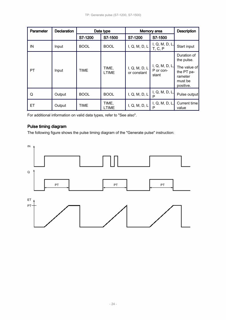
TP: TP: TP: TP: Generate Generate Generate Generate pulsepulsepulsepulse
Description
You can use the instruction "Generate pulse" to set output Q for the duration PT. The instruction isstarted when the result of logic operation (RLO) at input IN changes from "0" to "1" (positive signaledge). The configured time duration PT begins when the instruction starts. Output Q is set for the timeduration PT, regardless of the subsequent course of the input signal (positive edge). Even when anew positive signal edge is detected, the signal state of the Q output is not affected as long as the PTduration is running.
The current time value can be queried at the output ET. The time value starts at T#0s and ends whenthe value of the time duration PT is reached. If the configured time duration PT is reached and thesignal state at input IN is "0", the ET output is reset.
Each call of the "Generate pulse" instruction must be assigned an IEC Timer in which the instructiondata is stored.
NoteNoteNoteNoteIf the timer is not called in the program because it is skipped, for example, output ET returns a con‐stant value as soon as the timer has expired.
For For For For S7-1200 S7-1200 S7-1200 S7-1200 CPUCPUCPUCPUAn IEC Timer is a structure of the data type IEC_TIMER or TP_TIME that you can declare as follows:
• Declaration of a data block of system data type IEC_TIMER (for example, "MyIEC_TIMER")
• Declaration as a local tag of the type TP_TIME or IEC_TIMER in the "Static" section of a block (forexample, #MyIEC_TIMER)
For For For For S7-1500 S7-1500 S7-1500 S7-1500 CPUCPUCPUCPUAn IEC Timer is a structure of the data type IEC_TIMER, IEC_LTIMER, TP_TIME or TP_LTIME thatyou can declare as follows:
• Declaration of a data block of system data type IEC_TIMER or IEC_LTIMER (for example,"MyIEC_TIMER")• Declaration as a local tag of the type TP_TIME, TP_LTIME, IEC_TIMER or IEC_LTIMER in the
"Static" section of a block (for example, #MyIEC_TIMER)
When you insert the instruction in the program, the "Call options" dialog opens in which you can spec‐ify whether the IEC Timer is stored in its own data block (single instance) or as a local tag (multipleinstance) in the block interface. If you create a separate data block, you will find this in the project treein the "Program resources" folder under "Program blocks > System blocks". For additional informationon this topic, refer to "See also".
The instruction data is updated both when the instruction is called and also each time the outputs Q orET are accessed.
The execution of the "Generate pulse" instruction requires a preceding logic operation. It can beplaced within or at the end of the network.
ParametersParametersParametersParametersThe following table shows the parameters of the "Generate pulse" instruction:
TP: Generate pulse (S7-1200, S7-1500)
- 23 -
ParameterParameterParameterParameter DeclarationDeclarationDeclarationDeclaration Data Data Data Data typetypetypetype Memory Memory Memory Memory areaareaareaarea DescriptionDescriptionDescriptionDescriptionS7-1200S7-1200S7-1200S7-1200 S7-1500S7-1500S7-1500S7-1500 S7-1200S7-1200S7-1200S7-1200 S7-1500S7-1500S7-1500S7-1500
IN Input BOOL BOOL I, Q, M, D, L I, Q, M, D, L,T, C, P Start input
PT Input TIME TIME,LTIME
I, Q, M, D, Lor constant
I, Q, M, D, L,P or con‐stant
Duration ofthe pulse.
The value ofthe PT pa‐rametermust bepositive.
Q Output BOOL BOOL I, Q, M, D, L I, Q, M, D, L,P Pulse output
ET Output TIME TIME,LTIME I, Q, M, D, L I, Q, M, D, L,
PCurrent timevalue
For additional information on valid data types, refer to "See also".
Pulse Pulse Pulse Pulse timing timing timing timing diagramdiagramdiagramdiagramThe following figure shows the pulse timing diagram of the "Generate pulse" instruction:
TP: Generate pulse (S7-1200, S7-1500)
- 24 -

TON: TON: TON: TON: Generate Generate Generate Generate on-delayon-delayon-delayon-delay
Description
You can use the instruction "Generate on-delay" to delay setting of the Q output by the time config‐ured with the PT time. The instruction is started when the result of logic operation (RLO) at input INchanges from "0" to "1" (positive signal edge). The programmed time PT begins when the instructionstarts. When the duration PT expires, output Q has the signal state "1". Output Q remains set as longas the start input is still "1". When the signal state at the start input changes from "1" to "0", the Qoutput is reset. The timer function is started again when a new positive signal edge is detected at thestart input.
The current time value can be queried at the output ET. The time value starts at T#0s and ends whenthe value of the time duration PT is reached. The ET output is reset as soon as the signal state at theIN input changes to "0".
Each call of the "Generate on-delay" instruction must be assigned an IEC Timer in which the instruc‐tion data is stored.
NoteNoteNoteNoteIf the timer is not called in the program because it is skipped, for example, output ET returns a con‐stant value as soon as the timer has expired.
For For For For S7-1200 S7-1200 S7-1200 S7-1200 CPUCPUCPUCPUAn IEC Timer is a structure of the data type IEC_TIMER or TON_TIME that you can declare as fol‐lows:
• Declaration of a data block of system data type IEC_TIMER (for example, "MyIEC_TIMER")
• Declaration as a local tag of the type TON_TIME or IEC_TIMER in the "Static" section of a block(for example, #MyIEC_TIMER)
For For For For S7-1500 S7-1500 S7-1500 S7-1500 CPUCPUCPUCPUAn IEC Timer is a structure of the data type IEC_TIMER, IEC_LTIMER, TON_TIME or TON_LTIMEthat you can declare as follows:
• Declaration of a data block of system data type IEC_TIMER or IEC_LTIMER (for example,"MyIEC_TIMER")• Declaration as a local tag of the type TON_TIME, TON_LTIME, IEC_TIMER or IEC_LTIMER in the
"Static" section of a block (for example, #MyIEC_TIMER)
When you insert the instruction in the program, the "Call options" dialog opens in which you can spec‐ify whether the IEC Timer is stored in its own data block (single instance) or as a local tag (multipleinstance) in the block interface. If you create a separate data block, it is saved to the "Program resour‐ces" folder in the "Program blocks > System blocks" path of the project tree. For additional informationon this topic, refer to "See also".
The instruction data is updated both when the instruction is called and also each time the outputs Q orET are accessed.
The execution of the "Generate on-delay" instruction requires a preceding logic operation. It can beplaced within or at the end of the network.
ParametersParametersParametersParametersThe following table shows the parameters of the "Generate on-delay" instruction:
TON: Generate on-delay (S7-1200, S7-1500)
- 25 -

ParameterParameterParameterParameter DeclarationDeclarationDeclarationDeclaration Data Data Data Data typetypetypetype Memory Memory Memory Memory areaareaareaarea DescriptionDescriptionDescriptionDescriptionS7-1200S7-1200S7-1200S7-1200 S7-1500S7-1500S7-1500S7-1500 S7-1200S7-1200S7-1200S7-1200 S7-1500S7-1500S7-1500S7-1500
IN Input BOOL BOOL I, Q, M, D, L I, Q, M, D, L,T, C, P Start input
PT Input TIME TIME,LTIME
I, Q, M, D, Lor constant
I, Q, M, D, L,P or con‐stant
Duration ofthe on de‐lay.
The value ofthe PT pa‐rametermust bepositive.
Q Output BOOL BOOL I, Q, M, D, L I, Q, M, D, L,P
Output thatis set whenthe time PTexpires.
ET Output TIME TIME,LTIME I, Q, M, D, L I, Q, M, D, L,
PCurrent timevalue
For additional information on valid data types, refer to "See also".
Pulse Pulse Pulse Pulse timing timing timing timing diagramdiagramdiagramdiagramThe following figure shows the pulse timing diagram of the "Generate on-delay" instruction:
TON: Generate on-delay (S7-1200, S7-1500)
- 26 -

TOF: TOF: TOF: TOF: Generate Generate Generate Generate off-delayoff-delayoff-delayoff-delay
Description
You can use the "Generate off-delay" instruction to delay setting of the Q output by the time config‐ured with the PT time. The output Q is set when the result of logic operation (RLO) at input INchanges from "0" to "1" (positive signal edge). When the signal state at input IN changes back to "0"(positive signal edge), the configured time duration PT starts. Output Q remains set as long as thetime duration PT is running. When the PT time duration expires, the Q output is reset. If the signalstate at input IN changes to "1" before the PT time duration expires, the timer is reset. The signalstate at the output Q will continue to be "1".
The current time value can be queried at the output ET. The time value starts at T#0s and ends whenthe value of the time duration PT is reached. When the time duration PT expires, the ET output re‐mains set to the current value until input IN changes back to "1". If input IN changes to "1" before thetime duration PT has expired, the ET output is reset to the value T#0s.
Each call of the "Generate off-delay" instruction must be assigned to an IEC Timer in which the in‐struction data is stored.
NoteNoteNoteNoteIf the timer is not called in the program because it is skipped, for example, output ET returns a con‐stant value as soon as the timer has expired.
For For For For S7-1200 S7-1200 S7-1200 S7-1200 CPUCPUCPUCPUAn IEC Timer is a structure of the data type IEC_TIMER or TOF_TIME that you can declare as fol‐lows:
• Declaration of a data block of system data type IEC_TIMER (for example, "MyIEC_TIMER")
• Declaration as a local tag of the type TOF_TIME or IEC_TIMER in the "Static" section of a block(for example, #MyIEC_TIMER)
For For For For S7-1500 S7-1500 S7-1500 S7-1500 CPUCPUCPUCPUAn IEC Timer is a structure of the data type IEC_TIMER, IEC_LTIMER, TOF_TIME or TOF_LTIMEthat you can declare as follows:
• Declaration of a data block of system data type IEC_TIMER or IEC_LTIMER (for example,"MyIEC_TIMER")• Declaration as a local tag of the type TOF_TIME, TOF_LTIME, IEC_TIMER or IEC_LTIMER in the
"Static" section of a block (for example, #MyIEC_TIMER)
When you insert the instruction in the program, the "Call options" dialog opens in which you can spec‐ify whether the IEC Timer is stored in its own data block (single instance) or as a local tag (multipleinstance) in the block interface. If you create a separate data block, you will find this in the project treein the "Program resources" folder under "Program blocks > System blocks". For additional informationon this topic, refer to "See also".
The instruction data is updated both when the instruction is called and also each time the outputs Q orET are accessed.
The execution of the "Generate off-delay" instruction requires a preceding logic operation. It can beplaced within or at the end of the network.
ParametersParametersParametersParameters
TOF: Generate off-delay (S7-1200, S7-1500)
- 27 -

The following table shows the parameters of the "Generate off-delay" instruction:
ParameterParameterParameterParameter DeclarationDeclarationDeclarationDeclaration Data Data Data Data typetypetypetype Memory Memory Memory Memory areaareaareaarea DescriptionDescriptionDescriptionDescriptionS7-1200S7-1200S7-1200S7-1200 S7-1500S7-1500S7-1500S7-1500 S7-1200S7-1200S7-1200S7-1200 S7-1500S7-1500S7-1500S7-1500
IN Input BOOL BOOL I, Q, M, D, L I, Q, M, D, L,T, C, P Start input
PT Input TIME TIME,LTIME
I, Q, M, D, Lor constant
I, Q, M, D, L,P or con‐stant
Duration ofthe off delay
The value ofthe PT pa‐rametermust bepositive.
Q Output BOOL BOOL I, Q, M, D, L I, Q, M, D, L,P
Output thatis resetwhen thetimer PT ex‐pires.
ET Output TIME TIME,LTIME I, Q, M, D, L I, Q, M, D, L,
PCurrent timevalue
For additional information on valid data types, refer to "See also".
Pulse Pulse Pulse Pulse timing timing timing timing diagramdiagramdiagramdiagramThe following figure shows the pulse timing diagram of the "Generate off-delay" instruction:
TOF: Generate off-delay (S7-1200, S7-1500)
- 28 -
TONR: TONR: TONR: TONR: Time Time Time Time accumulatoraccumulatoraccumulatoraccumulator
Description
The instruction "Time accumulator" is used to accumulate time values within a period set by the pa‐rameter PT. The instruction is executed and the configured time duration PT is started when the resultof logic operation (RLO) at input IN changes from "0" to "1" (positive edge). While the time set at PT isrunning, the time values are accumulated that are recorded at signal state "1" at input IN. The accu‐mulated time is written to output ET and can be queried there. When the current time value PT isreached, the output Q has the signal state "1". Output Q remains set at "1", even when the signalstate at input IN changes to "0".
The R input resets the outputs ET and Q regardless of the signal state at the start input.
Each call of the "Time accumulator" instruction must be assigned to an IEC Timer in which the instruc‐tion data is stored.
For For For For S7-1200 S7-1200 S7-1200 S7-1200 CPUCPUCPUCPUAn IEC Timer is a structure of the data type IEC_TIMER or TONR_TIME that you can declare as fol‐lows:
• Declaration of a data block of system data type IEC_TIMER (for example, "MyIEC_TIMER")
• Declaration as a local tag of the type TONR_TIME or IEC_TIMER in the "Static" section of a block(for example, #MyIEC_TIMER)
For For For For S7-1500 S7-1500 S7-1500 S7-1500 CPUCPUCPUCPUAn IEC Timer is a structure of the data type IEC_TIMER, IEC_LTIMER, TONR_TIME or TONR_LTIMEthat you can declare as follows:
• Declaration of a data block of system data type IEC_TIMER or IEC_LTIMER (for example,"MyIEC_TIMER")• Declaration as a local tag of the type TONR_TIME, TONR_LTIME, IEC_TIMER or IEC_LTIMER in
the "Static" section of a block (for example, #MyIEC_TIMER)
When you insert the instruction in the program, the "Call options" dialog opens in which you can spec‐ify whether the IEC Timer is stored in its own data block (single instance) or as a local tag (multipleinstance) in the block interface. If you create a separate data block, you will find this in the project treein the "Program resources" folder under "Program blocks > System blocks". For additional informationon this topic, refer to "See also".
The instruction data is updated both when the instruction is called and also each time the outputs Q orET are accessed.
The execution of the "Time accumulator" instruction requires a preceding logic operation. It can beplaced within or at the end of the network.
ParametersParametersParametersParametersThe following table shows the parameters of the "Time accumulator" instruction:
TONR: Time accumulator (S7-1200, S7-1500)
- 29 -

ParameterParameterParameterParameter DeclarationDeclarationDeclarationDeclaration Data Data Data Data typetypetypetype Memory Memory Memory Memory areaareaareaarea DescriptionDescriptionDescriptionDescriptionS7-1200S7-1200S7-1200S7-1200 S7-1500S7-1500S7-1500S7-1500 S7-1200S7-1200S7-1200S7-1200 S7-1500S7-1500S7-1500S7-1500
IN Input BOOL BOOL I, Q, M, D, L I, Q, M, D, L,T, C, P Start input
R Input BOOL BOOL I, Q, M, D, Lor constant
I, Q, M, D, L,P or con‐stant
Reset input
PT Input TIME TIME,LTIME
I, Q, M, D, Lor constant
I, Q, M, D, L,P or con‐stant
Maximumduration oftime record‐ing.
The value ofthe PT pa‐rametermust bepositive.
Q Output BOOL BOOL I, Q, M, D, L I, Q, M, D, L,P
Output thatis set whenthe time PTexpires.
ET Output TIME TIME,LTIME I, Q, M, D, L I, Q, M, D, L,
PCurrent timevalue
For additional information on valid data types, refer to "See also".
Pulse Pulse Pulse Pulse timing timing timing timing diagramdiagramdiagramdiagramThe following figure shows the pulse timing diagram of the "Time accumulator" instruction:
TONR: Time accumulator (S7-1200, S7-1500)
- 30 -

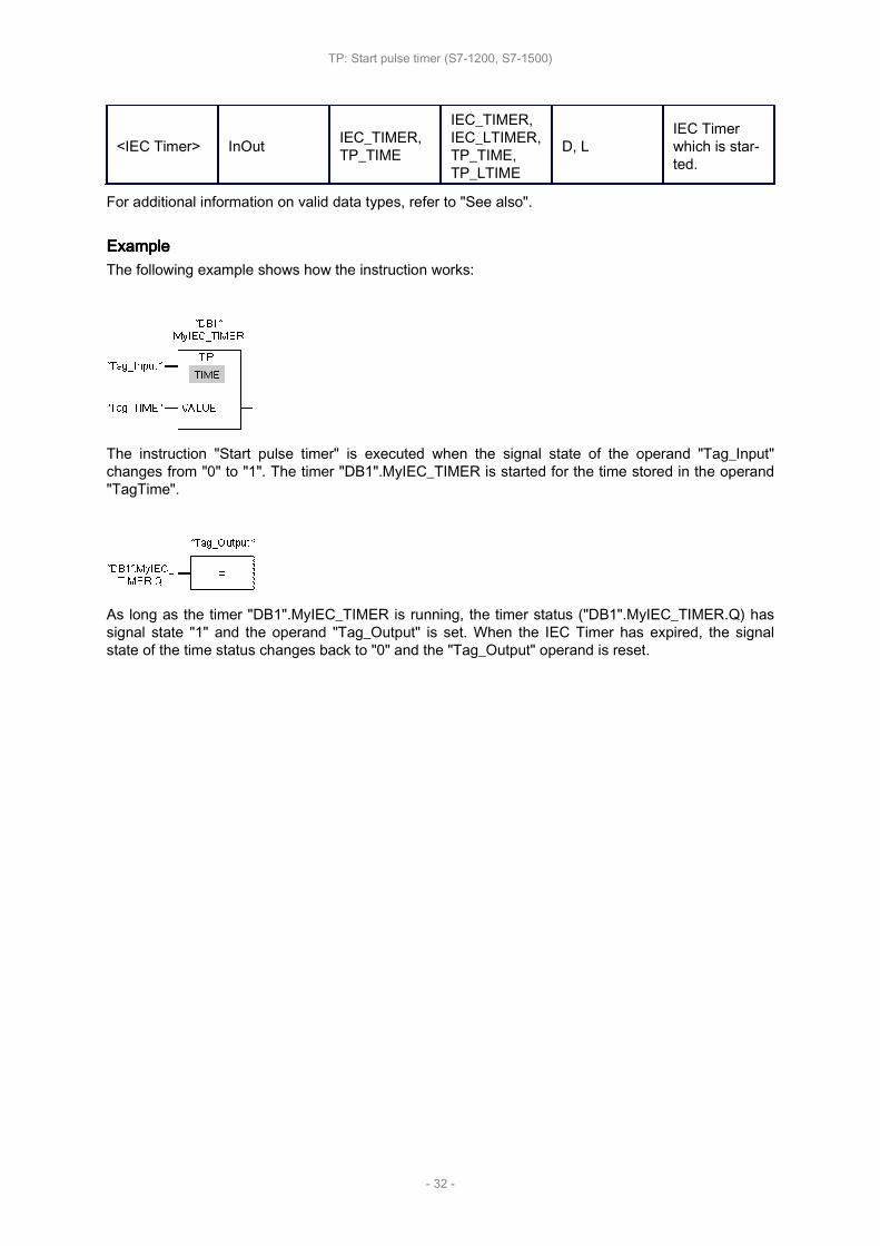
TP: TP: TP: TP: Start Start Start Start pulse pulse pulse pulse timertimertimertimer
Description
Use the instruction "Start pulse timer" to start an IEC Timer with a specified duration as pulse. TheIEC Timer is started when the result of logic operation (RLO) changes from "0" to "1" (positive signaledge). The IEC Timer runs for the specified time duration regardless of the subsequent course of theRLO. The expiry of the IEC Timer is also not affected by the detection of a new rising edge. As longas the IEC Timer is running, the querying of the timer status for "1" returns the signal state "1". Whenthe IEC Timer has expired, the timer status returns the signal state "0".
NoteNoteNoteNoteThe start and the query of the IEC Timer may be on different expiry levels as each query of theoutputs Q or ET updates the IEC_TIMER structure.
For For For For S7-1200 S7-1200 S7-1200 S7-1200 CPUCPUCPUCPUThe instruction "Start pulse timer" stores its data in a structure of the data type IEC_TIMER orTP_TIME. You can declare the structure as follows:
• Declaration of a data block of system data type IEC_TIMER (for example, "MyIEC_TIMER")
• Declaration as a local tag of the type TP_TIME or IEC_TIMER in the "Static" section of a block (forexample, #MyIEC_TIMER)
For For For For S7-1500 S7-1500 S7-1500 S7-1500 CPUCPUCPUCPUThe instruction "Start pulse timer" stores its data in a structure of the data type IEC_TIMER, IEC_LTI‐MER, TP_TIME or TP_LTIME. You can declare the structure as follows:
• Declaration of a data block of system data type IEC_TIMER or IEC_LTIMER (for example,"MyIEC_TIMER")• Declaration as a local tag of the type TP_TIME, TP_LTIME, IEC_TIMER or IEC_LTIMER in the
"Static" section of a block (for example, #MyIEC_TIMER)
The instruction data is updated both when the instruction is called and also each time the specifiedtimer is accessed.
The current timer status is saved in the structure components Q of the IEC Timer. You can query thetimer status with the help of a binary logic operation. The query for Q or ET (e. g. "MyTimer".Q or "My‐Timer".ET) updates the IEC_TIMER structure.
The execution of the instruction "Start pulse timer" assumes a preceding logic operation. It can beplaced only at the end of the network.
ParametersParametersParametersParametersThe following table shows the parameters of the instruction "Start pulse timer":
ParametersParametersParametersParameters DeclarationDeclarationDeclarationDeclaration Data Data Data Data typetypetypetype Memory Memory Memory Memory areaareaareaarea DescriptionDescriptionDescriptionDescriptionS7-1200S7-1200S7-1200S7-1200 S7-1500S7-1500S7-1500S7-1500
VALUE Input TIME TIME, LTIME I, Q, M, D, L orconstant
Duration withwhich the IECTimer runs.
TP: Start pulse timer (S7-1200, S7-1500)
- 31 -
<IEC Timer> InOut IEC_TIMER,TP_TIME
IEC_TIMER,IEC_LTIMER,TP_TIME,TP_LTIME
D, LIEC Timerwhich is star‐ted.
For additional information on valid data types, refer to "See also".
ExampleExampleExampleExampleThe following example shows how the instruction works:
The instruction "Start pulse timer" is executed when the signal state of the operand "Tag_Input"changes from "0" to "1". The timer "DB1".MyIEC_TIMER is started for the time stored in the operand"TagTime".
As long as the timer "DB1".MyIEC_TIMER is running, the timer status ("DB1".MyIEC_TIMER.Q) hassignal state "1" and the operand "Tag_Output" is set. When the IEC Timer has expired, the signalstate of the time status changes back to "0" and the "Tag_Output" operand is reset.
TP: Start pulse timer (S7-1200, S7-1500)
- 32 -

TON: TON: TON: TON: Start Start Start Start on-delay on-delay on-delay on-delay timertimertimertimer
Description
Use the "Start on-delay timer" instruction to start an IEC Timer with a specified duration as on-delay.The IEC Timer is started when the result of logic operation (RLO) changes from "0" to "1" (positivesignal edge). The IEC Timer runs for the specified time duration. The output returns the signal state"1" if the RLO at the input of the instruction has the signal state "1". If the RLO changes to "0" beforethe end of the timer, the running IEC Timer is reset. The query of the timer status for "1" returns thesignal state "0". The IEC Timer restarts when the next rising signal edge is detected at the input of theinstruction.
NoteNoteNoteNoteThe start and the query of the IEC Timer may be on different expiry levels as each query of theoutputs Q or ET updates the IEC_TIMER structure.
For For For For S7-1200 S7-1200 S7-1200 S7-1200 CPUCPUCPUCPUThe instruction "Start on-delay timer" stores its data in a structure of the data type IEC_TIMER orTON_TIME. You can declare the structure as follows:
• Declaration of a data block of system data type IEC_TIMER (for example, "MyIEC_TIMER")
• Declaration as a local tag of the type TON_TIME or IEC_TIMER in the "Static" section of a block(for example, #MyIEC_TIMER)
For For For For S7-1500 S7-1500 S7-1500 S7-1500 CPUCPUCPUCPUThe "Start on-delay timer" instruction stores its data in a structure of the data type IEC_TIMER,IEC_LTIMER, TON_TIME or TON_LTIME. You can declare the structure as follows:
• Declaration of a data block of system data type IEC_TIMER or IEC_LTIMER (for example,"MyIEC_TIMER")• Declaration as a local tag of the type TON_TIME, TON_LTIME, IEC_TIMER or IEC_LTIMER in the
"Static" section of a block (for example, #MyIEC_TIMER)
The instruction data is updated both when the instruction is called and also each time the specifiedtimer is accessed.
The current timer status is saved in the structure components ET of the IEC Timer. You can query thetimer status with the help of a binary logic operation. The query for Q or ET (e. g. "MyTimer".Q or "My‐Timer".ET) updates the IEC_TIMER structure.
The execution of the "Start on-delay timer" instruction assumes a preceding logic operation. It can beplaced only at the end of the network.
ParametersParametersParametersParametersThe following table shows the parameters of the instruction "Start on-delay timer":
TON: Start on-delay timer (S7-1200, S7-1500)
- 33 -

ParametersParametersParametersParameters DeclarationDeclarationDeclarationDeclaration Data Data Data Data typetypetypetype Memory Memory Memory Memory areaareaareaarea DescriptionDescriptionDescriptionDescriptionS7-1200S7-1200S7-1200S7-1200 S7-1500S7-1500S7-1500S7-1500
VALUE Input TIME TIME, LTIME I, Q, M, D, L orconstant
Duration withwhich the IECTimer runs.
<IEC Timer> InOut IEC_TIMER,TON_TIME
IEC_TIMER,IEC_LTIMER,TON_TIME,TON_LTIME
D, LIEC Timerwhich is star‐ted.
For additional information on valid data types, refer to "See also".
ExampleExampleExampleExampleThe following example shows how the instruction works:
The "Start on-delay timer" instruction is executed when the signal state of the operand "Tag_Input"changes from "0" to "1". The "MyIEC_TIMER" timer is started for the time stored in the "Tag_TIME"operand.
If the timer "MyIEC_TIMER" has expired and the operand "Tag_Input" has the signal state "1", query‐ing the timer status ("MyIEC_TIMER".Q) returns signal state "1" and the "Tag_Output" operand is set.When the signal state of the operand "Tag_Input" changes to "0", the querying of the timer status re‐turns the signal state "0" and the operand "Tag_Output" is reset.
TON: Start on-delay timer (S7-1200, S7-1500)
- 34 -

TOF: TOF: TOF: TOF: Start Start Start Start off-delay off-delay off-delay off-delay timertimertimertimer
Description
Use the "Start off-delay timer" instruction to start an IEC Timer with a specified duration as off-delay.The query of the timer status for "1" returns the signal state "0" if the result of the logic operation(RLO) at the input of the instruction has the signal state "1". When the RLO changes from "1" to "0"(negative signal edge), the IEC Timer starts with the specified time duration. The timer status remainsat signal state "1" as long as the IEC Timer is running. When the timer has run out and the RLO at theinput of the instruction has the signal state "0", the timer status is set to the signal state "0". If the RLOchanges to "1" before the end of the timer, the running IEC Timer is reset and the timer status remainat the signal state "1".
NoteNoteNoteNoteThe start and the query of the IEC Timer may be on different expiry levels as each query of theoutputs Q or ET updates the IEC_TIMER structure.
For For For For S7-1200 S7-1200 S7-1200 S7-1200 CPUCPUCPUCPUThe instruction "Start off-delay timer" stores its data in a structure of the data type IEC_TIMER orTOF_TIME. You can declare the structure as follows:
• Declaration of a data block of system data type IEC_TIMER (for example, "MyIEC_TIMER")
• Declaration as a local tag of the type TOF_TIME or IEC_TIMER in the "Static" section of a block(for example, #MyIEC_TIMER)
For For For For S7-1500 S7-1500 S7-1500 S7-1500 CPUCPUCPUCPUThe "Start off-delay timer" instruction stores its data in a structure of the data type IEC_TIMER,IEC_LTIMER, TOF_TIME or TOF_LTIME. You can declare the structure as follows:
• Declaration of a data block of system data type IEC_TIMER or IEC_LTIMER (for example,"MyIEC_TIMER")• Declaration as a local tag of the type TOF_TIME, TOF_LTIME, IEC_TIMER or IEC_LTIMER in the
"Static" section of a block (for example, #MyIEC_TIMER)
The instruction data is updated both when the instruction is called and also each time the specifiedtimer is accessed.
The current timer status is saved in the structure components ET of the IEC Timer. You can query thetimer status with the help of a binary logic operation. The query for Q or ET (e. g. "MyTimer".Q or "My‐Timer".ET) updates the IEC_TIMER structure.
The execution of the "Start off-delay timer" instruction assumes a preceding logic operation. It can beplaced only at the end of the network.
ParametersParametersParametersParametersThe following table shows the parameters of the instruction "Start off-delay timer":
TOF: Start off-delay timer (S7-1200, S7-1500)
- 35 -

ParametersParametersParametersParameters DeclarationDeclarationDeclarationDeclaration Data Data Data Data typetypetypetype Memory Memory Memory Memory areaareaareaarea DescriptionDescriptionDescriptionDescriptionS7-1200S7-1200S7-1200S7-1200 S7-1500S7-1500S7-1500S7-1500
VALUE Input TIME TIME, LTIME I, Q, M, D, L orconstant
Duration with whichthe IEC Timer runs.
<IEC Timer> InOut IEC_TIMER,TOF_TIME
IEC_TIMER,IEC_LTI‐MER,TOF_TIME,TOF_LTIME
D, L IEC Timer which isstarted.
For additional information on valid data types, refer to "See also".
ExampleExampleExampleExampleThe following example shows how the instruction works:
The "Start off-delay timer" instruction is executed when the signal state of the operand "Tag_Input"changes from "1" to "0". The #MyIEC_TIMER timer is started for the time stored in the operand"Tag_TIME".
As long as timer #MyIEC_TIMER is running, the query of the time status (#MyIEC_TIMER.Q) returnsthe signal state "1" and operand "Tag_Output" is set. If the timer has expired and the operand"Tag_Input" has the signal state "0", the query of the timer status returns the signal state "0". If thesignal state of the operand "Tag_Input" changes to "1" before timer #MyIEC_TIMER expires, the timeris reset. When the signal state of the operand "Tag_Input" is "1", the query of the timer status returnsthe signal state "1".
TOF: Start off-delay timer (S7-1200, S7-1500)
- 36 -
TONR: TONR: TONR: TONR: Time Time Time Time accumulatoraccumulatoraccumulatoraccumulator
Description
You can use the "Time accumulator" instruction to record how long the signal is at the input of instruc‐tion "1". The instruction is started when the result of logic operation (RLO) changes from "0" to "1"(positive signal edge). The time is recorded as long at the RLO is "1". If the RLO changes to "0", theinstruction is halted. If the RLO changes back to "1", the time recording is continued. The query of thetimer status for "1" returns the signal state "1" if the recorded time exceeds the value of the specifiedtime duration and the RLO at the input of coil is "1".
The timer status and the currently expired timer can be reset to "0" using the "Reset timer" instruction.
NoteNoteNoteNoteThe start and the query of the IEC Timer may be on different expiry levels as each query of theoutputs Q or ET updates the IEC_TIMER structure.
For For For For S7-1200 S7-1200 S7-1200 S7-1200 CPUCPUCPUCPUThe "Time accumulator" instruction stores its data in a structure of the data type IEC_TIMER orTONR_TIME. You can declare the structure as follows:
• Declaration of a data block of system data type IEC_TIMER (for example, "MyIEC_TIMER")
• Declaration as a local tag of the type TONR_TIME or IEC_TIMER in the "Static" section of a block(for example, #MyIEC_TIMER)
For For For For S7-1500 S7-1500 S7-1500 S7-1500 CPUCPUCPUCPUThe "Time accumulator" instruction stores its data in a structure of the data type IEC_TIMER,IEC_LTIMER, TONR_TIME or TONR_LTIME. You can declare the structure as follows:
• Declaration of a data block of system data type IEC_TIMER or IEC_LTIMER (for example,"MyIEC_TIMER")• Declaration as a local tag of the type TONR_TIME, TONR_LTIME, IEC_TIMER or IEC_LTIMER in
the "Static" section of a block (for example, #MyIEC_TIMER)
The instruction data is updated both when the instruction is called and also each time the specifiedtimer is accessed.
The current timer status is saved in the structure components ET of the IEC Timer. You can query thetimer status with the help of a binary logic operation. The query for Q or ET (e. g. "MyTimer".Q or "My‐Timer".ET) updates the IEC_TIMER structure.
The execution of the "Time accumulator" instruction requires a preceding logic operation. It can beplaced only at the end of the network.
ParametersParametersParametersParametersThe following table shows the parameters of the "Time accumulator" instruction:
TONR: Time accumulator (S7-1200, S7-1500)
- 37 -
ParametersParametersParametersParameters DeclarationDeclarationDeclarationDeclaration Data Data Data Data typetypetypetype Memory Memory Memory Memory areaareaareaarea Descrip‐Descrip‐Descrip‐Descrip‐tiontiontiontionS7-1200S7-1200S7-1200S7-1200 S7-1500S7-1500S7-1500S7-1500
VALUE Input TIME TIME, LTIME I, Q, M, D, L or con‐stant
Durationwithwhichthe IECTimerruns.
<IEC Timer> InOut IEC_TIMER,TONR_TIME
IEC_TIMER,IEC_LTIMER,TONR_TIME,TONR_LTIME
D, L
IEC Tim‐er whichis star‐ted.
For additional information on valid data types, refer to "See also".
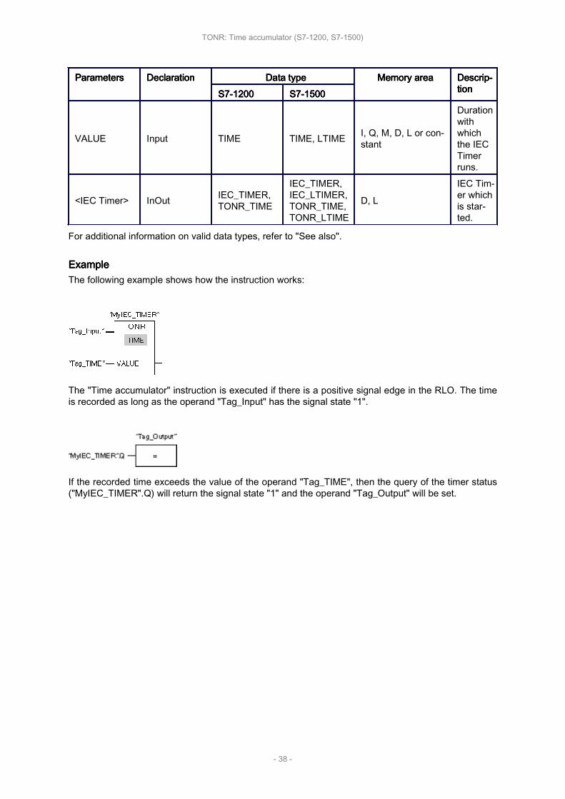
ExampleExampleExampleExampleThe following example shows how the instruction works:
The "Time accumulator" instruction is executed if there is a positive signal edge in the RLO. The timeis recorded as long as the operand "Tag_Input" has the signal state "1".
If the recorded time exceeds the value of the operand "Tag_TIME", then the query of the timer status("MyIEC_TIMER".Q) will return the signal state "1" and the operand "Tag_Output" will be set.
TONR: Time accumulator (S7-1200, S7-1500)
- 38 -

RT: RT: RT: RT: Reset Reset Reset Reset timertimertimertimer
Description
You can use the "Reset timer" instruction to reset an IEC Timer to "0". You specify the IEC Timer tobe reset by entering the name of the data block that contains the structure of the IEC Timer in theplaceholder above the instruction.
The instruction is only executed if the result of logic operation (RLO) at the box input is "1". When theinstruction is executed the structure components of the IEC Timer are reset to "0" in the specified datablock. If the RLO at box input is "0", the instruction is not executed.
The instruction does not influence the RLO. The RLO at the box input is transferred directly to the boxoutput.
You must assign a IEC Timer declared in the program to the "Reset timer" instruction.
The instruction data is updated only when the instruction is called and not each time the assigned IECTimer is accessed. The query of the data is only identical from the call of the instruction to the nextcall of the instruction.
ParametersParametersParametersParametersThe following table shows the parameters of the instruction "Reset timer":
ParametersParametersParametersParameters DeclarationDeclarationDeclarationDeclaration Data Data Data Data typetypetypetype Memory Memory Memory Memory areaareaareaarea DescriptionDescriptionDescriptionDescriptionS7-1200S7-1200S7-1200S7-1200 S7-1500S7-1500S7-1500S7-1500
<IEC Timer> InOut
IEC_TIMER,TP_TIME,TON_TIME,TOF_TIME,TONR_TIME
IEC_TIMER,IEC_LTIMER,TP_TIME,TP_LTIME,TON_TIME,TON_LTIME,TOF_TIME,TOF_LTIME,TONR_TIME,TONR_LTIME
D, L IEC Timer,which is reset.
For additional information on valid data types, refer to "See also".
ExampleExampleExampleExampleThe following example shows how the instruction works:
RT: Reset timer (S7-1200, S7-1500)
- 39 -
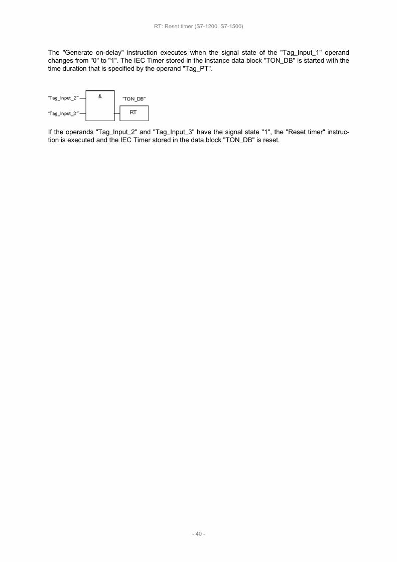
The "Generate on-delay" instruction executes when the signal state of the "Tag_Input_1" operandchanges from "0" to "1". The IEC Timer stored in the instance data block "TON_DB" is started with thetime duration that is specified by the operand "Tag_PT".
If the operands "Tag_Input_2" and "Tag_Input_3" have the signal state "1", the "Reset timer" instruc‐tion is executed and the IEC Timer stored in the data block "TON_DB" is reset.
RT: Reset timer (S7-1200, S7-1500)
- 40 -

PT: PT: PT: PT: Load Load Load Load time time time time durationdurationdurationduration
Description
Use the "Load time duration" instruction to set the time duration of an IEC Timer. The instruction isexecuted in every cycle when the result of logic operation (RLO) at the input of the instruction has thesignal state "1". The instruction writes the specified time duration to the structure of the specified IECTimer.
NoteNoteNoteNoteIf the specified IEC Timer is running during the execution, the instruction overwrites the current timeduration of the specified IEC Timer. As a result, the timer status of the IEC Timer can change.
You must assign a IEC Timer declared in the program to the "Load time duration" instruction.
The instruction data is updated when the instruction is called and each time the assigned IEC Timer isaccessed. The query for Q or ET (e. g. "MyTimer".Q or "MyTimer".ET) updates the IEC_TIMER struc‐ture.
ParametersParametersParametersParametersThe following table shows the parameters of the instruction "Load time duration":
ParametersParametersParametersParameters DeclarationDeclarationDeclarationDeclaration Data Data Data Data typetypetypetype Memory Memory Memory Memory areaareaareaarea DescriptionDescriptionDescriptionDescriptionS7-1200S7-1200S7-1200S7-1200 S7-1500S7-1500S7-1500S7-1500
PT Input TIME TIME, LTIME I, Q, M, D, L orconstant Time duration
<IEC Timer> InOut
IEC_TIMER,TP_TIME,TON_TIME,TOF_TIME,TONR_TIME
IEC_TIMER,IEC_LTIMER,TP_TIME,TP_LTIME,TON_TIME,TON_LTIME,TOF_TIME,TOF_LTIME,TONR_TIME,TONR_LTIME
D, LIEC Timer, theduration ofwhich is set.
For additional information on valid data types, refer to "See also".
ExampleExampleExampleExampleThe following example shows how the instruction works:
PT: Load time duration (S7-1200, S7-1500)
- 41 -

The "Generate on-delay" instruction executes when the signal state of the "Tag_Input_1" operandchanges from "0" to "1". The IEC Timer stored in the instance data block "TON_DB" is started with thetime duration that is specified by the operand "Tag_PT".
The "Load time duration" instruction is executed when the operand "Tag_Input_2" has the signal state"1". The instruction writes the time duration "Tag_PT_2" in the instance data block "TON_DB" and atthe same time overwrites the value of the operand "Tag_PT" within the data block. As a result, thesignal state of the timer status can change at the next query or upon access to "MyTimer".Q or "My‐Timer".ET.
NoteNoteNoteNoteThe "Tag_Input_2" is executed as pulse flag in order that the time duration is loaded only through‐out one program cycle.
PT: Load time duration (S7-1200, S7-1500)
- 42 -

SIMATIC SIMATIC SIMATIC SIMATIC TimersTimersTimersTimers
This chapter contains the following information:
• S_PULSE: S_PULSE: S_PULSE: S_PULSE: Assign Assign Assign Assign pulse pulse pulse pulse timer timer timer timer parameters parameters parameters parameters and and and and start start start start (S7-1500)(S7-1500)(S7-1500)(S7-1500)
• S_PEXT: S_PEXT: S_PEXT: S_PEXT: Assign Assign Assign Assign extended extended extended extended pulse pulse pulse pulse timer timer timer timer parameters parameters parameters parameters and and and and start start start start (S7-1500)(S7-1500)(S7-1500)(S7-1500)
• S_ODT: S_ODT: S_ODT: S_ODT: Assign Assign Assign Assign on-delay on-delay on-delay on-delay timer timer timer timer parameters parameters parameters parameters and and and and start start start start (S7-1500)(S7-1500)(S7-1500)(S7-1500)
• S_ODTS: S_ODTS: S_ODTS: S_ODTS: Assign Assign Assign Assign retentive retentive retentive retentive on-delay on-delay on-delay on-delay timer timer timer timer parameters parameters parameters parameters and and and and start start start start (S7-1500)(S7-1500)(S7-1500)(S7-1500)
• S_OFFDT: S_OFFDT: S_OFFDT: S_OFFDT: Assign Assign Assign Assign off-delay off-delay off-delay off-delay timer timer timer timer parameters parameters parameters parameters and and and and start start start start (S7-1500)(S7-1500)(S7-1500)(S7-1500)
• SP: SP: SP: SP: Start Start Start Start pulse pulse pulse pulse timer timer timer timer (S7-1500)(S7-1500)(S7-1500)(S7-1500)
• SE: SE: SE: SE: Start Start Start Start extended extended extended extended pulse pulse pulse pulse timer timer timer timer (S7-1500)(S7-1500)(S7-1500)(S7-1500)
• SD: SD: SD: SD: Start Start Start Start on-delay on-delay on-delay on-delay timer timer timer timer (S7-1500)(S7-1500)(S7-1500)(S7-1500)
• SS: SS: SS: SS: Start Start Start Start retentive retentive retentive retentive on-delay on-delay on-delay on-delay timer timer timer timer (S7-1500)(S7-1500)(S7-1500)(S7-1500)
• SF: SF: SF: SF: Start Start Start Start off-delay off-delay off-delay off-delay timer timer timer timer (S7-1500)(S7-1500)(S7-1500)(S7-1500)
SIMATIC Timers (S7-1500)
- 43 -

S_PULSE: S_PULSE: S_PULSE: S_PULSE: Assign Assign Assign Assign pulse pulse pulse pulse timer timer timer timer parameters parameters parameters parameters and and and and startstartstartstart
Description
The "Assign pulse timer parameters and start" instruction starts a programmed timer when a transitionfrom "0" to "1" (positive signal edge) is detected in the result of logic operation (RLO) at input S. Thetimer expires with the programmed duration (TV) as long as the signal state at input S is "1". If thesignal state at input S changes to "0" before the programmed duration expires, the timer is stopped. Inthis case, the signal state at output Q is "0".
The duration is made up internally of a time value and a time base and is programmed at parameterTV. When the instruction is started, the programmed time value is counted down to zero. The timebase determines the time period of the time value. The current time value is output binary-coded atoutput BI and BCD-coded at output BCD.
If the timer is running and the signal state at input R changes to "1", the current time value and thetime base are also set to zero. If the timer is not running, the signal state "1" at the R input has noeffect.
The "Assign pulse timer parameters and start" instruction needs a preceding logic operation for theedge evaluation and can be placed within or at the end of the network.
The instruction data is updated with each access. It can therefore happen that the query of the data atthe start of the cycle returns different values than at the end of the cycle.
NoteNoteNoteNoteIn the time cell, the operating system reduces the time value in an interval specified by the timebase by one unit until the value equals "0". The decrementation is performed asynchronously to theuser program. The resulting timer is therefore at maximum up to one time interval shorter than thedesired time base.
You can find an example of how a time cell can be formed under: See also "L: Load timer value".
ParametersParametersParametersParametersThe following table shows the parameters of the "Assign pulse timer parameters and start" instruction:
ParameterParameterParameterParameter DeclarationDeclarationDeclarationDeclaration Data Data Data Data typetypetypetype Memory Memory Memory Memory areaareaareaarea DescriptionDescriptionDescriptionDescription
<Timer> InOut/Input TIMER T
Time of the in‐struction
The number oftimers depends onthe CPU.
S Input BOOL I, Q, M, T, C, D, L,P Start input
TV Input S5TIME, WORD I, Q, M, D, L orconstant Time duration
R Input BOOL I, Q, M, T, C, D, L,P or constant Reset input
BI Output WORD I, Q, M, D, L, P Current time value(binary-coded)
S_PULSE: Assign pulse timer parameters and start (S7-1500)
- 44 -

BCD Output WORD I, Q, M, D, L, P Current time value(BCD format)
Q Output BOOL I, Q, M, D, L, P Status of the timer
For additional information on valid data types, refer to "See also".
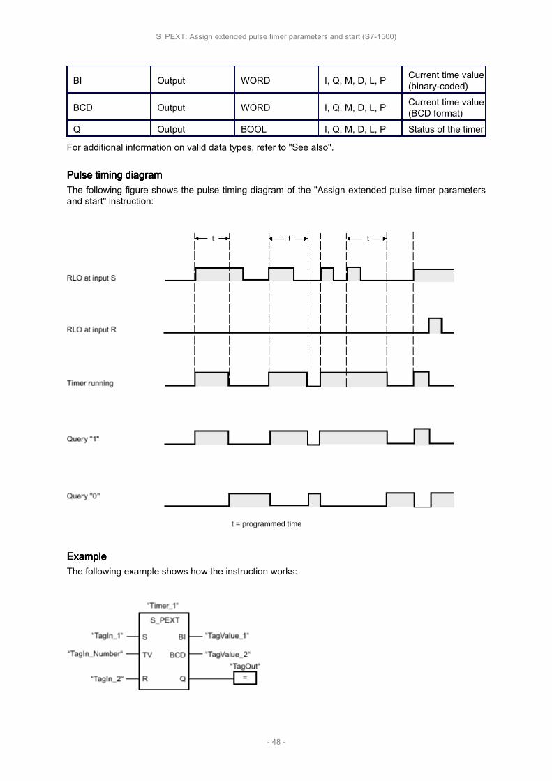
Pulse Pulse Pulse Pulse timing timing timing timing diagramdiagramdiagramdiagramThe following figure shows the pulse timing diagram of the "Assign pulse timer parameters and start"instruction:
ExampleExampleExampleExampleThe following example shows how the instruction works:
"Timer_1" starts when the signal state of the "TagIn_1" operand changes from "0" to "1". The timerruns for the time value of the "TagIn_Number" operand as long as the "TagIn_1" operand has the sig‐
S_PULSE: Assign pulse timer parameters and start (S7-1500)
- 45 -

nal state "1". If the signal state of the operand "TagIn_1" changes from "1" to "0" before the timer ex‐pires, the timer "Timer_1" is stopped. The "TagOut" operand is reset to signal state "0".
The "TagOut" operand has the signal state "1" as long as the timer is running and the "TagIn_1" oper‐and has the signal state "1". When the time has expired or is reset, the "TagOut" operand is reset to"0".
S_PULSE: Assign pulse timer parameters and start (S7-1500)
- 46 -

S_PEXT: S_PEXT: S_PEXT: S_PEXT: Assign Assign Assign Assign extended extended extended extended pulse pulse pulse pulse timer timer timer timer parameters parameters parameters parameters and and and and startstartstartstart
Description
The "Assign extended pulse timer parameters and start" instruction starts a programmed timer when atransition from "0" to "1" (positive signal edge) is detected in the result of logic operation (RLO) at in‐put S. The timer expires with the programmed duration (TV), even if the signal state at input Schanges to "0". As long as the timer is running, output Q has the signal state "1". When the timer hasexpired, output Q is reset to "0". If the signal state at input S changes from "0" to "1" while the timer isrunning, the timer is restarted with the duration programmed at input TV.
The duration is made up internally of a time value and a time base and is programmed at parameterTV. When the instruction is started, the programmed time value is counted down to zero. The timebase determines the time period of the time value. The current time value is output binary-coded atoutput BI and BCD-coded at output BCD.
If the timer is running and the signal state at input R changes to "1", the current time value and thetime base are also set to zero. If the timer is not running, the signal state "1" at the R input has noeffect.
The "Assign extended pulse timer parameters and start" instruction needs a preceding logic operationfor the edge evaluation and can be placed within or at the end of the network.
The instruction data is updated with each access. It can therefore happen that the query of the data atthe start of the cycle returns different values than at the end of the cycle.
NoteNoteNoteNoteIn the time cell, the operating system reduces the time value in an interval specified by the timebase by one unit until the value equals "0". The decrementation is performed asynchronously to theuser program. The resulting timer is therefore at maximum up to one time interval shorter than thedesired time base.
You can find an example of how a time cell can be formed under: See also "L: Load timer value".
ParametersParametersParametersParametersThe following table shows the parameters of the "Assign extended pulse timer parameters and start"instruction:
ParameterParameterParameterParameter DeclarationDeclarationDeclarationDeclaration Data Data Data Data typetypetypetype Memory Memory Memory Memory areaareaareaarea DescriptionDescriptionDescriptionDescription
<Timer> InOut/Input TIMER T
Time of the in‐struction
The number oftimers depends onthe CPU.
S Input BOOL I, Q, M, T, C, D, L,P Start input
TV Input S5TIME, WORD I, Q, M, D, L orconstant Time duration
R Input BOOL I, Q, M, T, C, D, L,P or constant Reset input
S_PEXT: Assign extended pulse timer parameters and start (S7-1500)
- 47 -
BI Output WORD I, Q, M, D, L, P Current time value(binary-coded)
BCD Output WORD I, Q, M, D, L, P Current time value(BCD format)
Q Output BOOL I, Q, M, D, L, P Status of the timer
For additional information on valid data types, refer to "See also".
Pulse Pulse Pulse Pulse timing timing timing timing diagramdiagramdiagramdiagramThe following figure shows the pulse timing diagram of the "Assign extended pulse timer parametersand start" instruction:
ExampleExampleExampleExampleThe following example shows how the instruction works:
S_PEXT: Assign extended pulse timer parameters and start (S7-1500)
- 48 -

"Timer_1" starts when the signal state of the "TagIn_1" operand changes from "0" to "1". The timerruns for the time value of the "TagIn_Number" operand without being affected by a negative edge atthe S input. If the signal state at the "TagIn_1" operand changes from "0" to "1" before the timer ex‐pires, the timer is restarted.
The "TagOut" operand has the signal state "1" as long as the timer is running. When the time hasexpired or is reset, the "TagOut" operand is reset to "0".
S_PEXT: Assign extended pulse timer parameters and start (S7-1500)
- 49 -

S_ODT: S_ODT: S_ODT: S_ODT: Assign Assign Assign Assign on-delay on-delay on-delay on-delay timer timer timer timer parameters parameters parameters parameters and and and and startstartstartstart
Description
The "Assign on-delay timer parameters and start" instruction starts a programmed timer when a tran‐sition from "0" to "1" (positive signal edge) is detected in the result of logic operation (RLO) at input S.The timer expires with the programmed duration (TV) as long as the signal state at input S is "1". Ifthe timer expires correctly and input S still has signal state "1", output Q returns signal state "1". If thesignal state at input S changes from "1" to "0" while the timer is running, the timer is stopped. In thiscase, output Q is reset to signal state "0".
The duration is made up internally of a time value and a time base and is programmed at parameterTV. When the instruction is started, the programmed time value is counted down to zero. The timebase determines the time period of the time value. The current time value is output binary-coded atoutput BI and BCD-coded at output BCD.
If the time is running and the signal state at input R changes from "0" to "1", the current time valueand the time base are also set to zero. In this case, the signal state at output Q is "0". The timer isreset if the signal state is "1" at the R input even if the timer is not running and the RLO at input S is"1".
The "Assign on-delay timer parameters and start" instruction needs a preceding logic operation for theedge evaluation and can be placed within or at the end of the network.
The instruction data is updated with each access. It can therefore happen that the query of the data atthe start of the cycle returns different values than at the end of the cycle.
NoteNoteNoteNoteIn the time cell, the operating system reduces the time value in an interval specified by the timebase by one unit until the value equals "0". The decrementation is performed asynchronously to theuser program. The resulting timer is therefore at maximum up to one time interval shorter than thedesired time base.
You can find an example of how a time cell can be formed under: See also "L: Load timer value".
ParametersParametersParametersParametersThe following table shows the parameters of the "Assign on-delay timer parameters and start" instruc‐tion:
ParameterParameterParameterParameter DeclarationDeclarationDeclarationDeclaration Data Data Data Data typetypetypetype Memory Memory Memory Memory areaareaareaarea DescriptionDescriptionDescriptionDescription
<Timer> InOut/Input TIMER T
Time of the in‐struction
The number oftimers depends onthe CPU.
S Input BOOL I, Q, M, T, C, D, L,P Start input
TV Input S5TIME, WORD I, Q, M, D, L orconstant Time duration
R Input BOOL I, Q, M, T, C, D, L,P or constant Reset input
S_ODT: Assign on-delay timer parameters and start (S7-1500)
- 50 -

BI Output WORD I, Q, M, D, L, P Current time value(binary-coded)
BCD Output WORD I, Q, M, D, L, P Current time value(BCD format)
Q Output BOOL I, Q, M, D, L, P Status of the timer
For additional information on valid data types, refer to "See also".
Pulse Pulse Pulse Pulse timing timing timing timing diagramdiagramdiagramdiagramThe following figure shows the pulse timing diagram of the "Assign on-delay timer parameters andstart" instruction:
ExampleExampleExampleExampleThe following example shows how the instruction works:
"Timer_1" starts when the signal state of the "TagIn_1" operand changes from "0" to "1". The timerexpires with the value of operand "TagIn_Number". If the timer expires and the signal state of the op‐erand is "1", the "TagOut" operand is set to "1". If the signal state at the "TagIn_1" operand changes
S_ODT: Assign on-delay timer parameters and start (S7-1500)
- 51 -

from "1" to "0" before the timer expires, the timer is stopped. The "TagOut" operand has the signalstate "0".
S_ODT: Assign on-delay timer parameters and start (S7-1500)
- 52 -

S_ODTS: S_ODTS: S_ODTS: S_ODTS: Assign Assign Assign Assign retentive retentive retentive retentive on-delay on-delay on-delay on-delay timer timer timer timer parameters parameters parameters parameters and and and and startstartstartstart
Description
The "Assign retentive on-delay timer parameters and start" instruction starts a programmed timerwhen a transition from "0" to "1" (positive signal edge) is detected in the result of logic operation(RLO) at input S. The timer expires with the programmed duration (TV), even if the signal state at in‐put S changes to "0". If the timer expires, the "Q" output returns signal state "1" regardless of the sig‐nal state at input "S". If the signal state at input S changes from "0" to "1" while the timer is running,the timer is restarted with the duration programmed at input (TV).
The duration is made up internally of a time value and a time base and is programmed at parameterTV. When the instruction is started, the programmed time value is counted down to zero. The timebase determines the time period of the time value. The current time value is output binary-coded atoutput BI and BCD-coded at output BCD.
Signal state "1" at input R resets the current time value and time base to "0" regardless of the signalstate at start input S. In this case, the signal state at output Q is "0".
The "Assign retentive on-delay timer parameters and start" instruction needs a preceding logic opera‐tion for the edge evaluation and can be placed within or at the end of the network.
The instruction data is updated with each access. It can therefore happen that the query of the data atthe start of the cycle returns different values than at the end of the cycle.
NoteNoteNoteNoteIn the time cell, the operating system reduces the time value in an interval specified by the timebase by one unit until the value equals "0". The decrementation is performed asynchronously to theuser program. The resulting timer is therefore at maximum up to one time interval shorter than thedesired time base.
You can find an example of how a time cell can be formed under: See also "L: Load timer value".
ParametersParametersParametersParametersThe following table shows the parameters of the "Assign retentive on-delay timer parameters andstart" instruction:
ParameterParameterParameterParameter DeclarationDeclarationDeclarationDeclaration Data Data Data Data typetypetypetype Memory Memory Memory Memory areaareaareaarea DescriptionDescriptionDescriptionDescription
<Timer> InOut/Input TIMER T
Time of the in‐struction
The number oftimers depends onthe CPU.
S Input BOOL I, Q, M, T, C, D, L,P Start input
TV Input S5TIME, WORD I, Q, M, D, L orconstant Time duration
R Input BOOL I, Q, M, T, C, D, L,P or constant Reset input
BI Output WORD I, Q, M, D, L, P Current time value(binary-coded)
S_ODTS: Assign retentive on-delay timer parameters and start (S7-1500)
- 53 -

BCD Output WORD I, Q, M, D, L, P Current time value(BCD format)
Q Output BOOL I, Q, M, D, L, P Status of the timer
For additional information on valid data types, refer to "See also".
Pulse Pulse Pulse Pulse timing timing timing timing diagramdiagramdiagramdiagramThe following figure shows the pulse timing diagram of the "Assign retentive on-delay timer parame‐ters and start" instruction:
ExampleExampleExampleExampleThe following example shows how the instruction works:
"Timer_1" starts when the signal state of the "TagIn_1" operand changes from "0" to "1". The timerexpires with the time value of the "TagIn_Number" operand, even when the signal state of the "Ta‐gIn_1" operand changes to "0". When the time expires, the "TagOut" operand is reset to "1". If thesignal state at the "TagIn_1" operand changes from "0" to "1" while the timer is running, the timer isrestarted.
S_ODTS: Assign retentive on-delay timer parameters and start (S7-1500)
- 54 -

S_OFFDT: S_OFFDT: S_OFFDT: S_OFFDT: Assign Assign Assign Assign off-delay off-delay off-delay off-delay timer timer timer timer parameters parameters parameters parameters and and and and startstartstartstart
Description
The "Assign off-delay timer parameters and start" instruction starts a programmed timer when a tran‐sition from "1" to "0" (negative signal edge) is detected in the result of logic operation (RLO) at inputS. The timer expires with the programmed duration (TV). As long as the timer is running or input Sreturns signal state "1", output Q has signal state "1". If the timer expires and the signal state is "0",output Q is reset to signal state "0". If the signal state at input S changes from "0" to "1" while thetimer is running, the timer is stopped. The timer is only restarted after a falling signal edge is detectedat input S.
The duration is made up internally of a time value and a time base and is programmed at parameterTV. When the instruction is started, the programmed time value is counted down to zero. The timebase determines the time period of the time value. The current time value is output binary-coded atoutput BI and BCD-coded at output BCD.
Signal state "1" at input R resets the current time value and time base to "0". In this case, the signalstate at output Q is "0".
The "Assign off-delay timer parameters and start" instruction needs a preceding logic operation for theedge evaluation and can be placed within or at the end of the network.
The instruction data is updated with each access. It can therefore happen that the query of the data atthe start of the cycle returns different values than at the end of the cycle.
NoteNoteNoteNoteIn the time cell, the operating system reduces the time value in an interval specified by the timebase by one unit until the value equals "0". The decrementation is performed asynchronously to theuser program. The resulting timer is therefore at maximum up to one time interval shorter than thedesired time base.
You can find an example of how a time cell can be formed under: See also "L: Load timer value".
ParametersParametersParametersParametersThe following table shows the parameters of the "Assign off-delay timer parameters and start" instruc‐tion:
ParameterParameterParameterParameter DeclarationDeclarationDeclarationDeclaration Data Data Data Data typetypetypetype Memory Memory Memory Memory areaareaareaarea DescriptionDescriptionDescriptionDescription
<Timer> InOut/Input TIMER T
Time of the in‐struction
The number oftimers depends onthe CPU.
S Input BOOL I, Q, M, T, C, D, L,P Start input
TV Input S5TIME, WORD I, Q, M, D, L orconstant Time duration
R Input BOOL I, Q, M, T, C, D, L,P or constant Reset input
S_OFFDT: Assign off-delay timer parameters and start (S7-1500)
- 55 -
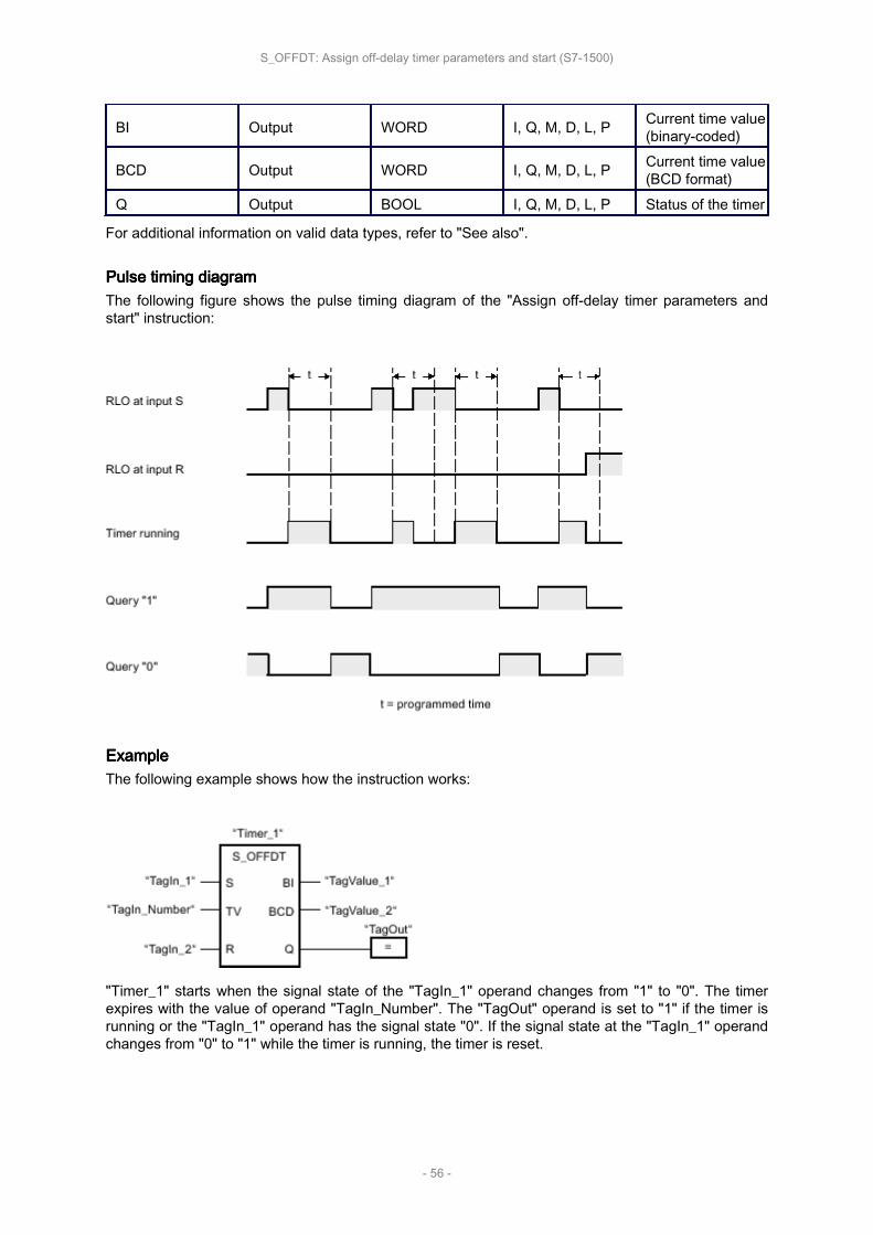
BI Output WORD I, Q, M, D, L, P Current time value(binary-coded)
BCD Output WORD I, Q, M, D, L, P Current time value(BCD format)
Q Output BOOL I, Q, M, D, L, P Status of the timer
For additional information on valid data types, refer to "See also".
Pulse Pulse Pulse Pulse timing timing timing timing diagramdiagramdiagramdiagramThe following figure shows the pulse timing diagram of the "Assign off-delay timer parameters andstart" instruction:
ExampleExampleExampleExampleThe following example shows how the instruction works:
"Timer_1" starts when the signal state of the "TagIn_1" operand changes from "1" to "0". The timerexpires with the value of operand "TagIn_Number". The "TagOut" operand is set to "1" if the timer isrunning or the "TagIn_1" operand has the signal state "0". If the signal state at the "TagIn_1" operandchanges from "0" to "1" while the timer is running, the timer is reset.
S_OFFDT: Assign off-delay timer parameters and start (S7-1500)
- 56 -

SP: SP: SP: SP: Start Start Start Start pulse pulse pulse pulse timertimertimertimer
Description
The instruction "Start pulse timer" starts a programmed timer when a change from "0" to "1" (positivesignal edge) is detected in the result of logic operation (RLO) at the start input. The timer runs with thespecified duration as long as the RLO has the signal state "1". As long as the timer is running, thequery of timer status "1" returns the signal state "1". If there is a change from "1" to "0" in the RLObefore the time value has elapsed, the timer stops. In this case, the query for timer status for "1" re‐turns the signal state "0".
The duration is made up internally of a time value and a time base and is programmed at parameterTV. When the instruction is started, the programmed time value is counted down to zero. The timebase determines the time period of the time value.
The "Start pulse timer" instruction needs a preceding logic operation for the edge evaluation and canonly be placed on the right edge of the network.
NoteNoteNoteNoteIn the time cell, the operating system reduces the time value in an interval specified by the timebase by one unit until the value equals "0". The decrementation is performed asynchronously to theuser program. The resulting timer is therefore at maximum up to one time interval shorter than thedesired time base.
You can find an example of how a time cell can be formed under: See also "L: Load timer value".
ParametersParametersParametersParametersThe following table shows the parameters of the instruction "Start pulse timer":
ParameterParameterParameterParameter DeclarationDeclarationDeclarationDeclaration Data Data Data Data typetypetypetype Memory Memory Memory Memory areaareaareaarea DescriptionDescriptionDescriptionDescription
<Operand> Input BOOL I, Q, M, T, C, D, L,P Start input
TV Input S5TIME, WORD I, Q, M, D, L orconstant Time duration
<Timer> InOut/Input TIMER T
Timer which isstarted.
The number oftimers depends onthe CPU.
For additional information on valid data types, refer to "See also".
ExampleExampleExampleExampleThe following example shows how the instruction works:
SP: Start pulse timer (S7-1500)
- 57 -

"Timer_1" starts when the signal state of the "TagIn_1" operand changes from "0" to "1". The timerexpires with the time value of the "TagIn_Number" operand as long as the signal state of the "Ta‐gIn_1" operand is "1". If the signal state at the "TagIn_1" operand changes from "1" to "0" before thetimer expires, the timer is stopped. As long as the timer is running, the "TagOut" operand returns sig‐nal state "1". If the signal state of the "TagIn_1" operand changes from "0" to "1", the timer is reset,i.e. the timer is stopped and the current time value is set to "0".
SP: Start pulse timer (S7-1500)
- 58 -

SE: SE: SE: SE: Start Start Start Start extended extended extended extended pulse pulse pulse pulse timertimertimertimer
Description
The "Start extended pulse timer" instruction starts a programmed timer when a change from "0" to "1"(positive signal edge) is detected in the result of logic operation (RLO) at the start input. The timerruns for the specified time period even when the RLO changes to signal state "0". As long as the timeris running, the query of timer status "1" returns the signal state "1". If the RLO changes from "0" to "1"while the timer is running, the timer is restarted with the programmed time period. When the timer ex‐pires, the query for timer status for "1" returns the signal state "0".
The duration is made up internally of a time value and a time base and is programmed at parameterTV. When the instruction is started, the programmed time value is counted down to zero. The timebase determines the time period of the time value.
The "Start extended pulse timer" instruction needs a preceding logic operation for the edge evaluationand can only be placed on the right edge of the network.
NoteNoteNoteNoteIn the time cell, the operating system reduces the time value in an interval specified by the timebase by one unit until the value equals "0". The decrementation is performed asynchronously to theuser program. The resulting timer is therefore at maximum up to one time interval shorter than thedesired time base.
You can find an example of how a time cell can be formed under: See also "L: Load timer value".
ParametersParametersParametersParametersThe following table shows the parameters of the instruction "Start extended pulse timer":
ParameterParameterParameterParameter DeclarationDeclarationDeclarationDeclaration Data Data Data Data typetypetypetype Memory Memory Memory Memory areaareaareaarea DescriptionDescriptionDescriptionDescription
<Operand> Input BOOL I, Q, M, T, C, D, L,P Start input
TV Input S5TIME, WORD I, Q, M, D, L orconstant Time duration
<Timer> InOut/Input TIMER T
Timer which isstarted.
The number oftimers depends onthe CPU.
For additional information on valid data types, refer to "See also".
ExampleExampleExampleExampleThe following example shows how the instruction works:
SE: Start extended pulse timer (S7-1500)
- 59 -

"Timer_1" starts when the signal state of the "TagIn_1" operand changes from "0" to "1". The timerexpires with the time value of the "TagIn_Number" operand without being affected by a negative edgeat the RLO. As long as the timer is running, the "TagOut" operand returns signal state "1". If the signalstate at the "TagIn_1" operand changes from "0" to "1" before the timer expires, the timer is restarted.
SE: Start extended pulse timer (S7-1500)
- 60 -

SD: SD: SD: SD: Start Start Start Start on-delay on-delay on-delay on-delay timertimertimertimer
Description
The "Start on-delay timer" instruction starts a programmed timer when a change from "0" to "1" (posi‐tive signal edge) is detected in the result of logic operation (RLO) at the start input. The timer runs forthe specified period of time as long as the RLO is "1". If the timer expires and the RLO has the signalstate "1", the query timer status "1" returns the signal state "1". If the RLO changes from "1" to "0"while the timer is running, the timer is stopped. In this case, querying the timer status for "1" returnsthe signal state "0".
The duration is made up internally of a time value and a time base and is programmed at parameterTV. When the instruction is started, the programmed time value is counted down to zero. The timebase determines the time period of the time value.
The "Start on-delay timer" instruction needs a preceding logic operation for the edge evaluation andcan only be placed on the right edge of the network.
NoteNoteNoteNoteIn the time cell, the operating system reduces the time value in an interval specified by the timebase by one unit until the value equals "0". The decrementation is performed asynchronously to theuser program. The resulting timer is therefore at maximum up to one time interval shorter than thedesired time base.
You can find an example of how a time cell can be formed under: See also "L: Load timer value".
ParametersParametersParametersParametersThe following table shows the parameters of the instruction "Start on-delay timer":
ParameterParameterParameterParameter DeclarationDeclarationDeclarationDeclaration Data Data Data Data typetypetypetype Memory Memory Memory Memory areaareaareaarea DescriptionDescriptionDescriptionDescription
<Operand> Input BOOL I, Q, M, T, C, D, L,P Start input
TV Input S5TIME, WORD I, Q, M, D, L orconstant Time duration
<Timer> InOut/Input TIMER T
Timer which isstarted.
The number oftimers depends onthe CPU.
For additional information on valid data types, refer to "See also".
ExampleExampleExampleExampleThe following example shows how the instruction works:
SD: Start on-delay timer (S7-1500)
- 61 -
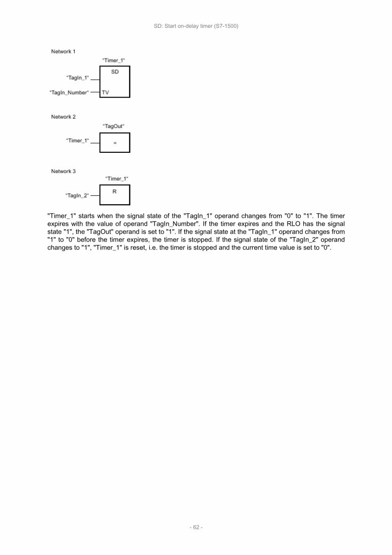
"Timer_1" starts when the signal state of the "TagIn_1" operand changes from "0" to "1". The timerexpires with the value of operand "TagIn_Number". If the timer expires and the RLO has the signalstate "1", the "TagOut" operand is set to "1". If the signal state at the "TagIn_1" operand changes from"1" to "0" before the timer expires, the timer is stopped. If the signal state of the "TagIn_2" operandchanges to "1", "Timer_1" is reset, i.e. the timer is stopped and the current time value is set to "0".
SD: Start on-delay timer (S7-1500)
- 62 -

SS: SS: SS: SS: Start Start Start Start retentive retentive retentive retentive on-delay on-delay on-delay on-delay timertimertimertimer
Description
The "Start retentive on-delay timer" instruction starts a programmed timer when a change from "0" to"1" (positive signal edge) is detected in the result of logic operation (RLO) at the start input. The timerruns for the specified time period even when the RLO changes to signal state "0". When the timerexpires, the query for timer status for "1" returns the signal state "1". When the timer expires, the timercan only be restarted if it is explicitly reset.
The duration is made up internally of a time value and a time base and is programmed at parameterTV. When the instruction is started, the programmed time value is counted down to zero. The timebase determines the time period of the time value.
The "Start retentive on-delay timer" instruction needs a preceding logic operation for the edge evalua‐tion and can only be placed on the right edge of the network.
NoteNoteNoteNoteIn the time cell, the operating system reduces the time value in an interval specified by the timebase by one unit until the value equals "0". The decrementation is performed asynchronously to theuser program. The resulting timer is therefore at maximum up to one time interval shorter than thedesired time base.
You can find an example of how a time cell can be formed under: See also "L: Load timer value".
ParametersParametersParametersParametersThe following table shows the parameters of the instruction "Start retentive on-delay timer":
ParameterParameterParameterParameter DeclarationDeclarationDeclarationDeclaration Data Data Data Data typetypetypetype Memory Memory Memory Memory areaareaareaarea DescriptionDescriptionDescriptionDescription
<Operand> Input BOOL I, Q, M, T, C, D, L,P Start input
TV Input S5TIME, WORD I, Q, M, D, L orconstant Time duration
<Timer> InOut/Input TIMER T
Timer which isstarted.
The number oftimers depends onthe CPU.
For additional information on valid data types, refer to "See also".
ExampleExampleExampleExampleThe following example shows how the instruction works:
SS: Start retentive on-delay timer (S7-1500)
- 63 -
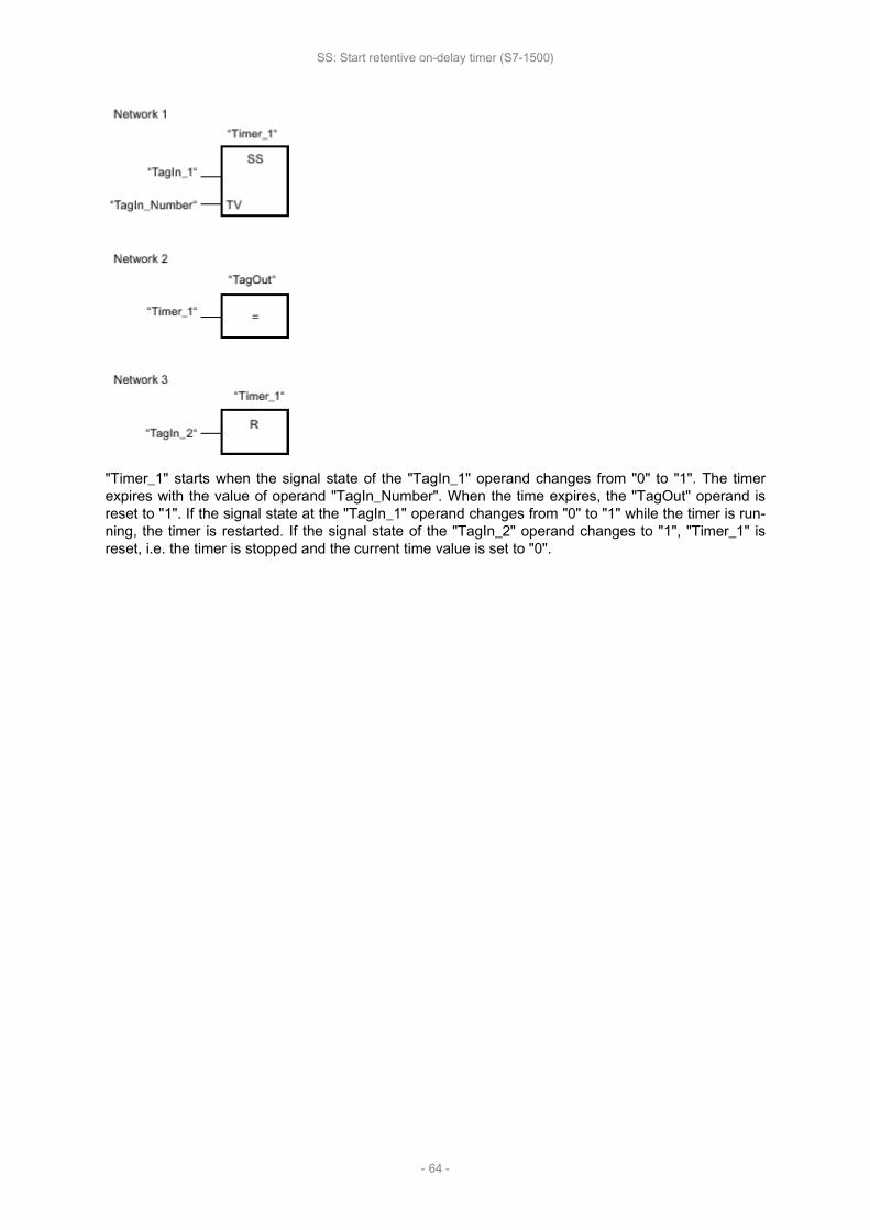
"Timer_1" starts when the signal state of the "TagIn_1" operand changes from "0" to "1". The timerexpires with the value of operand "TagIn_Number". When the time expires, the "TagOut" operand isreset to "1". If the signal state at the "TagIn_1" operand changes from "0" to "1" while the timer is run‐ning, the timer is restarted. If the signal state of the "TagIn_2" operand changes to "1", "Timer_1" isreset, i.e. the timer is stopped and the current time value is set to "0".
SS: Start retentive on-delay timer (S7-1500)
- 64 -
SF: SF: SF: SF: Start Start Start Start off-delay off-delay off-delay off-delay timertimertimertimer
Description
The "Start off-delay timer" instruction starts a programmed timer when a change from "1" to "0" (nega‐tive signal edge) is detected in the result of logic operation (RLO) at the start input. The timer runs forthe specified time period. As long as the timer is running, the query of timer status "1" returns the sig‐nal state "1". If the RLO changes from "0" to "1" while the timer is running, the timer is reset. The timeris always restarted when the RLO changes from "1" to "0".
The duration is made up internally of a time value and a time base and is programmed at parameterTV. When the instruction is started, the programmed time value is counted down to zero. The timebase determines the time period of the time value.
The "Start off-delay timer" instruction needs a preceding logic operation for the edge evaluation andcan only be placed on the right edge of the network.
NoteNoteNoteNoteIn the time cell, the operating system reduces the time value in an interval specified by the timebase by one unit until the value equals "0". The decrementation is performed asynchronously to theuser program. The resulting timer is therefore at maximum up to one time interval shorter than thedesired time base.
You can find an example of how a time cell can be formed under: See also "L: Load timer value".
ParametersParametersParametersParametersThe following table shows the parameters of the instruction "Start off-delay timer":
ParameterParameterParameterParameter DeclarationDeclarationDeclarationDeclaration Data Data Data Data typetypetypetype Memory Memory Memory Memory areaareaareaarea DescriptionDescriptionDescriptionDescription
<Operand> Input BOOL I, Q, M, T, C, D, L,P Start input
TV Input S5TIME, WORD I, Q, M, D, L orconstant Time duration
<Timer> InOut/Input TIMER T
Timer which isstarted.
The number oftimers depends onthe CPU.
For additional information on valid data types, refer to "See also".
ExampleExampleExampleExampleThe following example shows how the instruction works:
SF: Start off-delay timer (S7-1500)
- 65 -

"Timer_1" starts when the signal state of the "TagIn_1" operand changes from "1" to "0". The timerexpires with the value of operand "TagIn_Number". As long as the timer is running, the "TagOut" op‐erand is set to "1". If the signal state at the "TagIn_1" operand changes from "1" to "0" while the timeris running, the timer is restarted. If the signal state of the "TagIn_2" operand changes to "1", "Timer_1"is reset, i.e. the timer is stopped and the current time value is set to "0".
SF: Start off-delay timer (S7-1500)
- 66 -

Counter Counter Counter Counter operationsoperationsoperationsoperations
This chapter contains the following information:
• IEC IEC IEC IEC Counters Counters Counters Counters (S7-1200, (S7-1200, (S7-1200, (S7-1200, S7-1500)S7-1500)S7-1500)S7-1500)
• SIMATIC SIMATIC SIMATIC SIMATIC counters counters counters counters (S7-1500)(S7-1500)(S7-1500)(S7-1500)
Counter operations (S7-1200, S7-1500)
- 67 -

IEC IEC IEC IEC CountersCountersCountersCounters
This chapter contains the following information:
• CTU: CTU: CTU: CTU: Count Count Count Count up up up up (S7-1200, (S7-1200, (S7-1200, (S7-1200, S7-1500)S7-1500)S7-1500)S7-1500)
• CTD: CTD: CTD: CTD: Count Count Count Count down down down down (S7-1200, (S7-1200, (S7-1200, (S7-1200, S7-1500)S7-1500)S7-1500)S7-1500)
• CTUD: CTUD: CTUD: CTUD: Count Count Count Count up up up up and and and and down down down down (S7-1200, (S7-1200, (S7-1200, (S7-1200, S7-1500)S7-1500)S7-1500)S7-1500)
IEC Counters (S7-1200, S7-1500)
- 68 -
CTU: CTU: CTU: CTU: Count Count Count Count upupupup
Description
You can use the "Count up" instruction to increment the value at output CV. When the signal state atthe CU input changes from "0" to "1" (positive signal edge), the instruction is executed and the currentcounter value at the CV output is incremented by one. When the instruction executes for the first time,the current counter value at the CV output is set to zero. The counter is incremented each time a posi‐tive signal edge is detected, until it reaches the high limit for the specified data type at output CV.When the high limit is reached, the signal state at the CU input no longer has an effect on the instruc‐tion.
You can scan the counter status at the Q output. The signal state at the Q output is determined by thePV parameter. If the current counter value is greater than or equal to the value of the PV parameter,the Q output is set to signal state "1". In all other cases, the Q output has signal state "0". You canalso specify a constant for the PV parameter.
The value at the CV output is reset to "0" and saved to an edge memory bit when the signal state atinput R changes to "1". As long as the R input has the signal state "1", the signal state at the CU inputhas no effect on the instruction.
NoteNoteNoteNoteOnly use a counter at a single point in the program to avoid the risk of counting errors.
Each call of the "Count up" instruction must be assigned an IEC counter in which the instruction datais stored. An IEC counter is a structure with one of the following data types:
For For For For S7-1200 S7-1200 S7-1200 S7-1200 CPUCPUCPUCPU
Data Data Data Data block block block block of of of of system system system system data data data data type type type type IEC_<Counter>IEC_<Counter>IEC_<Counter>IEC_<Counter>(Shared (Shared (Shared (Shared DB)DB)DB)DB)
Local Local Local Local tagtagtagtag
• IEC_SCOUNTER / IEC_USCOUNTER• IEC_COUNTER / IEC_UCOUNTER• IEC_DCOUNTER / IEC_UDCOUNTER
• CTU_SINT / CTU_USINT• CTU_INT / CTU_UINT• CTU_DINT / CTU_UDINT• IEC_SCOUNTER / IEC_USCOUNTER• IEC_COUNTER / IEC_UCOUNTER• IEC_DCOUNTER / IEC_UDCOUNTER
For For For For S7-1500 S7-1500 S7-1500 S7-1500 CPUCPUCPUCPU
Data Data Data Data block block block block of of of of system system system system data data data data type type type type IEC_<Counter>IEC_<Counter>IEC_<Counter>IEC_<Counter>(Shared (Shared (Shared (Shared DB)DB)DB)DB)
Local Local Local Local tagtagtagtag
• IEC_SCOUNTER / IEC_USCOUNTER• IEC_COUNTER / IEC_UCOUNTER• IEC_DCOUNTER / IEC_UDCOUNTER• IEC_LCOUNTER / IEC_ULCOUNTER
• CTU_SINT / CTU_USINT• CTU_INT / CTU_UINT• CTU_DINT / CTU_UDINT• CTU_LINT / CTU_ULINT• IEC_SCOUNTER / IEC_USCOUNTER• IEC_COUNTER / IEC_UCOUNTER
CTU: Count up (S7-1200, S7-1500)
- 69 -

• IEC_DCOUNTER / IEC_UDCOUNTER• IEC_LCOUNTER / IEC_ULCOUNTER
You can declare an IEC counter as follows:
• Declaration of a data block of system data type IEC_<Counter> (for example, "MyIEC_COUNTER")
• Declaration as a local tag of the type CTU_<Data type> or IEC_<Counter> in the "Static" section ofa block (for example #MyIEC_COUNTER)
When you insert the instruction in the program, the "Call options" dialog opens in which you can spec‐ify whether the IEC counter is stored in its own data block (single instance) or as a local tag (multipleinstance) in the block interface. If you create a separate data block, it is saved to the "Program resour‐ces" folder in the "Program blocks > System blocks" path of the project tree. For additional informationon this topic, refer to "See also".
When you set up the IEC counter in a separate data block (single instance), the instance data block iscreated by default with "optimized block access" and the individual tags are defined as retentive. Foradditional information on setting retentivity in an instance data block, refer to "See also".
When you set up the IEC counter as local tag (multiple instance) in a function block with "optimizedblock access", it is defined as retentive in the block interface.
The execution of the "Count up" instruction requires a preceding logic operation. It can be placed with‐in or at the end of the network.
ParametersParametersParametersParametersThe following table shows the parameters of the "Count up" instruction:
ParametersParametersParametersParameters DeclarationDeclarationDeclarationDeclaration Data Data Data Data typetypetypetype Memory Memory Memory Memory areaareaareaarea DescriptionDescriptionDescriptionDescriptionS7-1200S7-1200S7-1200S7-1200 S7-1500S7-1500S7-1500S7-1500
CU Input BOOL I, Q, M, D, Lor constant
I, Q, M, D, L orconstant Count input
R Input BOOLI, Q, M, D, L,P or con‐stant
I, Q, M, T, C,D, L, P or con‐stant
Reset input
PV Input IntegersI, Q, M, D, L,P or con‐stant
I, Q, M, D, L, Por constant
Value at whichthe output Q isset.
Q Output BOOL I, Q, M, D, L I, Q, M, D, L Counter status
CV Output Integers,CHAR, DATE
I, Q, M, D, L,P I, Q, M, D, L, P Current counter
value
You can select the data type of the instruction from the "<???>" drop-down list of the instruction box.
For additional information on valid data types, refer to "See also".
ExampleExampleExampleExampleThe following example shows how the instruction works:
CTU: Count up (S7-1200, S7-1500)
- 70 -

When the signal state of the "TagIn_1" operand changes from "0" to "1", the "Count up" instructionexecutes and the current counter value of the "Tag_CV" operand is incremented by one. With eachadditional positive signal edge, the counter value is incremented until the high limit of the specifieddata type (INT = 32767) is reached.
The value of the PV parameter is adopted as the limit for determining the "TagOut" output. The "Tag‐Out" output has signal state "1" as long as the current counter value is greater than or equal to thevalue of the "Tag_PV" operand. In all other cases, the "TagOut" output returns the signal state "0".
CTU: Count up (S7-1200, S7-1500)
- 71 -

CTD: CTD: CTD: CTD: Count Count Count Count downdowndowndown
Description
You can use the "Count down" instruction to decrement the value at output CV. When the signal stateat the CD input changes from "0" to "1" (positive signal edge), the instruction is executed and the cur‐rent counter value at the CV output is decremented by one. When the instruction is executed the firsttime, the counter value of the CV parameter is set to the value of the PV parameter. Each time a posi‐tive signal edge is detected, the counter value is decremented until it reaches the low limit of thespecified data type. When the low limit is reached, the signal state at the CD input no longer has aneffect on the instruction.
You can scan the counter status at the Q output. If the current counter value is less than or equal to"0", the Q output is set to signal state "1". In all other cases, the Q output has signal state "0". You canalso specify a constant for the PV parameter.
The value at the CV output is set to the value of the PV parameter and saved to a edge memory bitwhen the signal state at the LD input changes from "0" to "1". As long as the LD input has the signalstate "1", the signal state at the CD input has no effect on the instruction.
NoteNoteNoteNoteOnly use a counter at a single point in the program to avoid the risk of counting errors.
Each call of the "Count down" instruction must be assigned an IEC counter in which the instructiondata is stored. An IEC counter is a structure with one of the following data types:
For For For For S7-1200 S7-1200 S7-1200 S7-1200 CPUCPUCPUCPU
Data Data Data Data block block block block of of of of system system system system data data data data type type type type IEC_<Counter>IEC_<Counter>IEC_<Counter>IEC_<Counter>(Shared (Shared (Shared (Shared DB)DB)DB)DB)
Local Local Local Local tagtagtagtag
• IEC_SCOUNTER / IEC_USCOUNTER• IEC_COUNTER / IEC_UCOUNTER• IEC_DCOUNTER / IEC_UDCOUNTER
• CTD_SINT / CTD_USINT• CTD_INT / CTD_UINT• CTD_DINT / CTD_UDINT• IEC_SCOUNTER / IEC_USCOUNTER• IEC_COUNTER / IEC_UCOUNTER• IEC_DCOUNTER / IEC_UDCOUNTER
For For For For S7-1500 S7-1500 S7-1500 S7-1500 CPUCPUCPUCPU
Data Data Data Data block block block block of of of of system system system system data data data data type type type type IEC_<Counter>IEC_<Counter>IEC_<Counter>IEC_<Counter>(Shared (Shared (Shared (Shared DB)DB)DB)DB)
Local Local Local Local tagtagtagtag
• IEC_SCOUNTER / IEC_USCOUNTER• IEC_COUNTER / IEC_UCOUNTER• IEC_DCOUNTER / IEC_UDCOUNTER• IEC_LCOUNTER / IEC_ULCOUNTER
• CTD_SINT / CTD_USINT• CTD_INT / CTD_UINT• CTD_DINT / CTD_UDINT• CTD_LINT / CTD_ULINT• IEC_SCOUNTER / IEC_USCOUNTER• IEC_COUNTER / IEC_UCOUNTER
CTD: Count down (S7-1200, S7-1500)
- 72 -

• IEC_DCOUNTER / IEC_UDCOUNTER• IEC_LCOUNTER / IEC_ULCOUNTER
You can declare an IEC counter as follows:
• Declaration of a data block of system data type IEC_<Counter> (for example, "MyIEC_COUNTER")
• Declaration as a local tag of the type CTD_<Data type> or IEC_<Counter> in the "Static" section ofa block (for example #MyIEC_COUNTER)
When you insert the instruction in the program, the "Call options" dialog opens in which you can spec‐ify whether the IEC counter is stored in its own data block (single instance) or as a local tag (multipleinstance) in the block interface. If you create a separate data block, it is saved to the "Program resour‐ces" folder in the "Program blocks > System blocks" path of the project tree. For additional informationon this topic, refer to "See also".
When you set up the IEC counter in a separate data block (single instance), the instance data block iscreated by default with "optimized block access" and the individual tags are defined as retentive. Foradditional information on setting retentivity in an instance data block, refer to "See also".
When you set up the IEC counter as local tag (multiple instance) in a function block with "optimizedblock access", it is defined as retentive in the block interface.
The execution of the "Count down" instruction requires a preceding logic operation. It can be placedwithin or at the end of the network.
ParametersParametersParametersParametersThe following table shows the parameters of the "Count down" instruction:
ParametersParametersParametersParameters DeclarationDeclarationDeclarationDeclaration Data Data Data Data typetypetypetype Memory Memory Memory Memory areaareaareaarea DescriptionDescriptionDescriptionDescriptionS7-1200S7-1200S7-1200S7-1200 S7-1500S7-1500S7-1500S7-1500
CD Input BOOL I, Q, M, D, Lor constant
I, Q, M, D, L orconstant Count input
LD Input BOOLI, Q, M, D, L,P or con‐stant
I, Q, M, T, C,D, L, P or con‐stant
Load input
PV Input IntegersI, Q, M, D, L,P or con‐stant
I, Q, M, D, L, Por constant
Value at whichthe output Q isset.
Q Output BOOL I, Q, M, D, L I, Q, M, D, L Counter status
CV Output Integers,CHAR, DATE
I, Q, M, D, L,P I, Q, M, D, L, P Current counter
value
You can select the data type of the instruction from the "<???>" drop-down list of the instruction box.
For additional information on valid data types, refer to "See also".
ExampleExampleExampleExampleThe following example shows how the instruction works:
CTD: Count down (S7-1200, S7-1500)
- 73 -
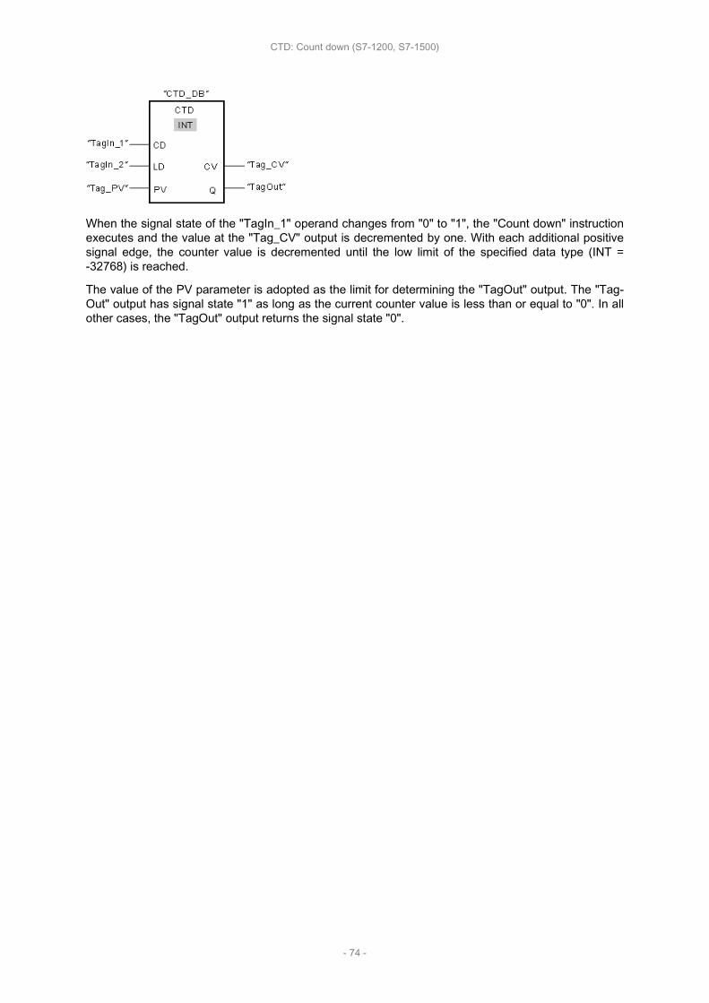
When the signal state of the "TagIn_1" operand changes from "0" to "1", the "Count down" instructionexecutes and the value at the "Tag_CV" output is decremented by one. With each additional positivesignal edge, the counter value is decremented until the low limit of the specified data type (INT =-32768) is reached.
The value of the PV parameter is adopted as the limit for determining the "TagOut" output. The "Tag‐Out" output has signal state "1" as long as the current counter value is less than or equal to "0". In allother cases, the "TagOut" output returns the signal state "0".
CTD: Count down (S7-1200, S7-1500)
- 74 -

CTUD: CTUD: CTUD: CTUD: Count Count Count Count up up up up and and and and downdowndowndown
Description
You can use the "Count up and down" instruction to increment and decrement the counter value atthe CV output. If the signal state at the CU input changes from "0" to "1" (positive signal edge), thecurrent counter value is incremented by one and stored at the CV output. If the signal state at the CDinput changes from "0" to "1" (positive signal edge), the current counter value at the CV output is de‐cremented by one. If there is a positive signal edge at the CU and CD inputs in one program cycle,the current counter value at the CV output remains unchanged.
The counter value can be incremented until it reaches the high limit of the data type specified at theCV output. When the high limit is reached, the counter value is no longer incremented on a positivesignal edge. When the low limit of the specified data type is reached, the counter value is not decre‐mented any further.
When the signal state at the LD input changes to "1", the counter value at the CV output is set to thevalue of the PV parameter and stored in a edge memory bit. As long as the LD input has the signalstate "1", the signal state at the CU and CD inputs has no effect on the instruction.
The counter value is set to "0" and stored in an edge memory bit when the signal state at input Rchanges to "1". As long as the R input has the signal state "1", a change in the signal state of the CU,CD and LD inputs has no effect on the "Count up and down" instruction.
You can scan the current status of the up counter at the QU output. If the current counter value isgreater than or equal to the value of the PV parameter, the QU output is set to signal state "1". In allother cases, the QU output has signal state "0". You can also specify a constant for the PV parame‐ter.
You can scan the current status of the down counter at the QD output. If the current counter value isless than or equal to zero, the QD output is set to signal state "1". In all other cases, the QD outputhas signal state "0".
NoteNoteNoteNoteOnly use a counter at a single point in the program to avoid the risk of counting errors.
Each call of the "Count up and down" instruction must be assigned an IEC counter in which the in‐struction data is stored. An IEC counter is a structure with one of the following data types:
For For For For S7-1200 S7-1200 S7-1200 S7-1200 CPUCPUCPUCPU
Data Data Data Data block block block block of of of of system system system system data data data data type type type type IEC_<Counter>IEC_<Counter>IEC_<Counter>IEC_<Counter>(Shared (Shared (Shared (Shared DB)DB)DB)DB)
Local Local Local Local tagtagtagtag
• IEC_SCOUNTER / IEC_USCOUNTER• IEC_COUNTER / IEC_UCOUNTER• IEC_DCOUNTER / IEC_UDCOUNTER
• CTUD_SINT / CTUD_USINT• CTUD_INT / CTUD_UINT• CTUD_DINT / CTUD_UDINT• IEC_SCOUNTER / IEC_USCOUNTER• IEC_COUNTER / IEC_UCOUNTER• IEC_DCOUNTER / IEC_UDCOUNTER
For For For For S7-1500 S7-1500 S7-1500 S7-1500 CPUCPUCPUCPU
CTUD: Count up and down (S7-1200, S7-1500)
- 75 -

Data Data Data Data block block block block of of of of system system system system data data data data type type type type IEC_<Counter>IEC_<Counter>IEC_<Counter>IEC_<Counter>(Shared (Shared (Shared (Shared DB)DB)DB)DB)
Local Local Local Local tagtagtagtag
• IEC_SCOUNTER / IEC_USCOUNTER• IEC_COUNTER / IEC_UCOUNTER• IEC_DCOUNTER / IEC_UDCOUNTER• IEC_LCOUNTER / IEC_ULCOUNTER
• CTUD_SINT / CTUD_USINT• CTUD_INT / CTUD_UINT• CTUD_DINT / CTUD_UDINT• CTUD_LINT / CTUD_ULINT• IEC_SCOUNTER / IEC_USCOUNTER• IEC_COUNTER / IEC_UCOUNTER• IEC_DCOUNTER / IEC_UDCOUNTER• IEC_LCOUNTER / IEC_ULCOUNTER
You can declare an IEC counter as follows:
• Declaration of a data block of system data type IEC_<Counter> (for example, "MyIEC_COUNTER")
• Declaration as a local tag of the type CTUD_<Data type> or IEC_<Counter> in the "Static" sectionof a block (for example #MyIEC_COUNTER)
When you insert the instruction in the program, the "Call options" dialog opens in which you can spec‐ify whether the IEC counter is stored in its own data block (single instance) or as a local tag (multipleinstance) in the block interface. If you create a separate data block, it is saved to the "Program resour‐ces" folder in the "Program blocks > System blocks" path of the project tree. For additional informationon this topic, refer to "See also".
When you set up the IEC counter in a separate data block (single instance), the instance data block iscreated by default with "optimized block access" and the individual tags are defined as retentive. Foradditional information on setting retentivity in an instance data block, refer to "See also".
When you set up the IEC counter as local tag (multiple instance) in a function block with "optimizedblock access", it is defined as retentive in the block interface.
The execution of the "Count up and down" instruction requires a preceding logic operation. It can beplaced within or at the end of the network.
ParametersParametersParametersParametersThe following table shows the parameters of the "Count up and down" instruction:
ParameterParameterParameterParameter DeclarationDeclarationDeclarationDeclaration Data Data Data Data typetypetypetype Memory Memory Memory Memory areaareaareaarea DescriptionDescriptionDescriptionDescriptionS7-1200S7-1200S7-1200S7-1200 S7-1500S7-1500S7-1500S7-1500
CU Input BOOL I, Q, M, D, Lor constant
I, Q, M, D, L orconstant Count up input
CD Input BOOL I, Q, M, D, Lor constant
I, Q, M, D, L orconstant
Count down in‐put
R Input BOOLI, Q, M, D, L,P or con‐stant
I, Q, M, T, C,D, L, P or con‐stant
Reset input
LD Input BOOLI, Q, M, D, L,P or con‐stant
I, Q, M, T, C,D, L, P or con‐stant
Load input
PV Input IntegersI, Q, M, D, L,P or con‐stant
I, Q, M, D, L, Por constant
Value at whichthe output QUis set.
CTUD: Count up and down (S7-1200, S7-1500)
- 76 -

QU Output BOOL I, Q, M, D, L I, Q, M, D, L Up-counter sta‐tus
QD Output BOOL I, Q, M, D, L I, Q, M, D, L Down-counterstatus
CV Output Integers,CHAR, DATE
I, Q, M, D, L,P I, Q, M, D, L, P Current counter
value
You can select the data type of the instruction from the "<???>" drop-down list of the instruction box.
For additional information on valid data types, refer to "See also".
ExampleExampleExampleExampleThe following example shows how the instruction works:
If the signal state at the "TagIn_CU" or "TagIn_CD" input changes from "0" to "1" (positive signaledge), the "Count up and down" instruction is executed. When there is a positive signal edge at the"TagIn_CU" input, the current counter value is incremented by one and stored at the "Tag_CV" output.When there is a positive signal edge at the "TagIn_CD" input, the counter value is decremented byone and stored at the "Tag_CV" output. When there is a positive edge at the CU input, the countervalue is incremented until it reaches the high limit (INT = 32767). If input CD has a positive signaledge, the counter value is decremented until it reaches the low limit (INT = -32768).
The "TagOut_GU" output has signal state "1" as long as the current counter value is greater than orequal to the value at the "Tag_PV" input. In all other cases, the "TagOut_QU" output returns the signalstate "0".
The "TagOut_QD" output has signal state "1" as long as the current counter value is less than orequal to "0". In all other cases, the "TagOut_QD" output has signal state "0".
CTUD: Count up and down (S7-1200, S7-1500)
- 77 -

SIMATIC SIMATIC SIMATIC SIMATIC counterscounterscounterscounters
This chapter contains the following information:
• S_CUD: S_CUD: S_CUD: S_CUD: Assign Assign Assign Assign parameters parameters parameters parameters and and and and count count count count up up up up / / / / down down down down (S7-1500)(S7-1500)(S7-1500)(S7-1500)
• S_CU: S_CU: S_CU: S_CU: Assign Assign Assign Assign parameters parameters parameters parameters and and and and count count count count up up up up (S7-1500)(S7-1500)(S7-1500)(S7-1500)
• S_CD: S_CD: S_CD: S_CD: Assign Assign Assign Assign parameters parameters parameters parameters and and and and count count count count down down down down (S7-1500)(S7-1500)(S7-1500)(S7-1500)
• SC: SC: SC: SC: Set Set Set Set counter counter counter counter value value value value (S7-1500)(S7-1500)(S7-1500)(S7-1500)
• CU: CU: CU: CU: Count Count Count Count up up up up (S7-1500)(S7-1500)(S7-1500)(S7-1500)
• CD: CD: CD: CD: Count Count Count Count down down down down (S7-1500)(S7-1500)(S7-1500)(S7-1500)
SIMATIC counters (S7-1500)
- 78 -
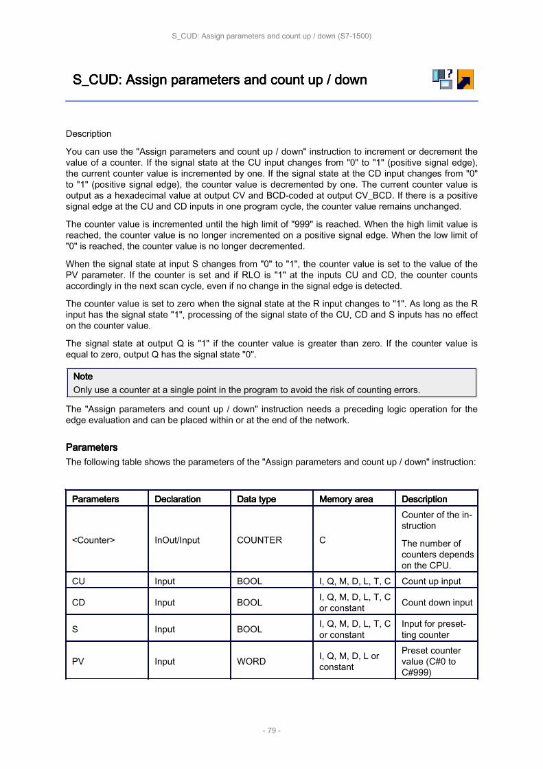
S_CUD: S_CUD: S_CUD: S_CUD: Assign Assign Assign Assign parameters parameters parameters parameters and and and and count count count count up up up up / / / / downdowndowndown
Description
You can use the "Assign parameters and count up / down" instruction to increment or decrement thevalue of a counter. If the signal state at the CU input changes from "0" to "1" (positive signal edge),the current counter value is incremented by one. If the signal state at the CD input changes from "0"to "1" (positive signal edge), the counter value is decremented by one. The current counter value isoutput as a hexadecimal value at output CV and BCD-coded at output CV_BCD. If there is a positivesignal edge at the CU and CD inputs in one program cycle, the counter value remains unchanged.
The counter value is incremented until the high limit of "999" is reached. When the high limit value isreached, the counter value is no longer incremented on a positive signal edge. When the low limit of"0" is reached, the counter value is no longer decremented.
When the signal state at input S changes from "0" to "1", the counter value is set to the value of thePV parameter. If the counter is set and if RLO is "1" at the inputs CU and CD, the counter countsaccordingly in the next scan cycle, even if no change in the signal edge is detected.
The counter value is set to zero when the signal state at the R input changes to "1". As long as the Rinput has the signal state "1", processing of the signal state of the CU, CD and S inputs has no effecton the counter value.
The signal state at output Q is "1" if the counter value is greater than zero. If the counter value isequal to zero, output Q has the signal state "0".
NoteNoteNoteNoteOnly use a counter at a single point in the program to avoid the risk of counting errors.
The "Assign parameters and count up / down" instruction needs a preceding logic operation for theedge evaluation and can be placed within or at the end of the network.
ParametersParametersParametersParametersThe following table shows the parameters of the "Assign parameters and count up / down" instruction:
ParametersParametersParametersParameters DeclarationDeclarationDeclarationDeclaration Data Data Data Data typetypetypetype Memory Memory Memory Memory areaareaareaarea DescriptionDescriptionDescriptionDescription
<Counter> InOut/Input COUNTER C
Counter of the in‐struction
The number ofcounters dependson the CPU.
CU Input BOOL I, Q, M, D, L, T, C Count up input
CD Input BOOL I, Q, M, D, L, T, Cor constant Count down input
S Input BOOL I, Q, M, D, L, T, Cor constant
Input for preset‐ting counter
PV Input WORD I, Q, M, D, L orconstant
Preset countervalue (C#0 toC#999)
S_CUD: Assign parameters and count up / down (S7-1500)
- 79 -

R Input BOOL I, Q, M, D, L, T, Cor constant Reset input
CV Output WORD, S5TIME,DATE I, Q, M, D, L
Current countervalue (hexadeci‐mal)
CV_BCD Output WORD, S5TIME,DATE I, Q, M, D, L
Current countervalue (BCD for‐mat)
Q Output BOOL I, Q, M, D, L Status of thecounter
For additional information on valid data types, refer to "See also".
ExampleExampleExampleExampleThe following example shows how the instruction works:
If the signal state at the "TagIn_1" or "TagIn_2" input changes from "0" to "1" (positive signal edge),the "Assign parameters and count up / down" instruction is executed. When there is a positive signaledge at the "TagIn_1" input and the current counter value is less than "999", the counter value is in‐cremented by one. When there is a positive signal edge at the "TagIn_2" input and the current countervalue is greater than "0", the counter value is decremented by one.
When the signal state at the "TagIn_3" input changes from "0" to "1", the counter value is set to thevalue of the "TagPresetValue" operand. The counter value is reset to "0" when the "TagIn_4" operandhas signal state "1".
The current counter value is hexadecimal in the "TagValue_1" operand and BCD-coded in the "Tag‐Value_2" operand.
The "TagOut" output has the signal state "1" as long as the current counter value is not equal to "0".
S_CUD: Assign parameters and count up / down (S7-1500)
- 80 -
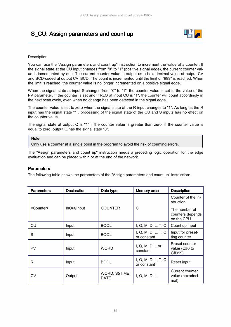
S_CU: S_CU: S_CU: S_CU: Assign Assign Assign Assign parameters parameters parameters parameters and and and and count count count count upupupup
Description
You can use the "Assign parameters and count up" instruction to increment the value of a counter. Ifthe signal state at the CU input changes from "0" to "1" (positive signal edge), the current counter val‐ue is incremented by one. The current counter value is output as a hexadecimal value at output CVand BCD-coded at output CV_BCD. The count is incremented until the limit of "999" is reached. Whenthe limit is reached, the counter value is no longer incremented on a positive signal edge.
When the signal state at input S changes from "0" to "1", the counter value is set to the value of thePV parameter. If the counter is set and if RLO at input CU is "1", the counter will count accordingly inthe next scan cycle, even when no change has been detected in the signal edge.
The counter value is set to zero when the signal state at the R input changes to "1". As long as the Rinput has the signal state "1", processing of the signal state of the CU and S inputs has no effect onthe counter value.
The signal state at output Q is "1" if the counter value is greater than zero. If the counter value isequal to zero, output Q has the signal state "0".
NoteNoteNoteNoteOnly use a counter at a single point in the program to avoid the risk of counting errors.
The "Assign parameters and count up" instruction needs a preceding logic operation for the edgeevaluation and can be placed within or at the end of the network.
ParametersParametersParametersParametersThe following table shows the parameters of the "Assign parameters and count up" instruction:
ParametersParametersParametersParameters DeclarationDeclarationDeclarationDeclaration Data Data Data Data typetypetypetype Memory Memory Memory Memory areaareaareaarea DescriptionDescriptionDescriptionDescription
<Counter> InOut/Input COUNTER C
Counter of the in‐struction
The number ofcounters dependson the CPU.
CU Input BOOL I, Q, M, D, L, T, C Count up input
S Input BOOL I, Q, M, D, L, T, Cor constant
Input for preset‐ting counter
PV Input WORD I, Q, M, D, L orconstant
Preset countervalue (C#0 toC#999)
R Input BOOL I, Q, M, D, L, T, Cor constant Reset input
CV Output WORD, S5TIME,DATE I, Q, M, D, L
Current countervalue (hexadeci‐mal)
S_CU: Assign parameters and count up (S7-1500)
- 81 -

CV_BCD Output WORD, S5TIME,DATE I, Q, M, D, L
Current countervalue (BCD for‐mat)
Q Output BOOL I, Q, M, D, L Status of thecounter
For additional information on valid data types, refer to "See also".
ExampleExampleExampleExampleThe following example shows how the instruction works:
When the signal state at the "TagIn_1" input changes from "0" to "1" (positive signal edge) and thecurrent counter value is less than "999", the counter value is incremented by one. When the signalstate at the "TagIn_2" input changes from "0" to "1", the counter value is set to the value of the "Tag‐PresetValue" operand. The counter value is reset to "0" when the "TagIn_3" operand has signal state"1".
The current counter value is hexadecimal in the "TagValue_1" operand and BCD-coded in the "Tag‐Value_2" operand.
The "TagOut" output has the signal state "1" as long as the current counter value is not equal to "0".
S_CU: Assign parameters and count up (S7-1500)
- 82 -

S_CD: S_CD: S_CD: S_CD: Assign Assign Assign Assign parameters parameters parameters parameters and and and and count count count count downdowndowndown
Description
You can use the "Assign parameters and count down" instruction to decrement the value of a counter.If the signal state at the CD input changes from "0" to "1" (positive signal edge), the counter value isdecremented by one. The current counter value is output as a hexadecimal value at output CV andBCD-coded at output CV_BCD. The count is decremented until the low limit of "0" is reached. Whenthe low limit is reached, the counter value is no longer decremented on a positive signal edge.
When the signal state at input S changes from "0" to "1", the counter value is set to the value of thePV parameter. If the counter is set and if RLO at input CD is "1", the counter will count accordingly inthe next scan cycle, even when no change has been detected in the signal edge.
The counter value is set to zero when the signal state at the R input changes to "1". As long as the Rinput has the signal state "1", processing of the signal state of the CD and S inputs has no effect onthe counter value.
The signal state at output Q is "1" if the counter value is greater than zero. If the counter value isequal to zero, output Q has the signal state "0".
NoteNoteNoteNoteOnly use a counter at a single point in the program to avoid the risk of counting errors.
The "Assign parameters and count down" instruction needs a preceding logic operation for the edgeevaluation and can be placed within or at the end of the network.
ParametersParametersParametersParametersThe following table shows the parameters of the "Assign parameters and count down" instruction:
ParametersParametersParametersParameters DeclarationDeclarationDeclarationDeclaration Data Data Data Data typetypetypetype Memory Memory Memory Memory areaareaareaarea DescriptionDescriptionDescriptionDescription
<Counter> InOut/Input COUNTER C
Counter of the in‐struction
The number ofcounters dependson the CPU.
CD Input BOOL I, Q, M, D, L orconstant Count down input
S Input BOOL I, Q, M, D, L, T, Cor constant
Input for preset‐ting counter
PV Input WORD I, Q, M, D, L orconstant
Preset countervalue (C#0 toC#999)
R Input BOOL I, Q, M, D, L, T, Cor constant Reset input
CV Output WORD, S5TIME,DATE I, Q, M, D, L
Current countervalue (hexadeci‐mal)
S_CD: Assign parameters and count down (S7-1500)
- 83 -
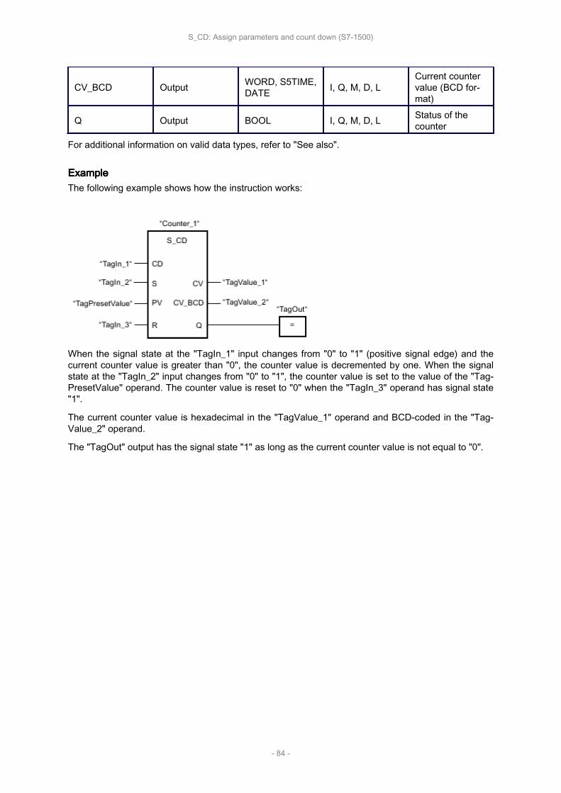
CV_BCD Output WORD, S5TIME,DATE I, Q, M, D, L
Current countervalue (BCD for‐mat)
Q Output BOOL I, Q, M, D, L Status of thecounter
For additional information on valid data types, refer to "See also".
ExampleExampleExampleExampleThe following example shows how the instruction works:
When the signal state at the "TagIn_1" input changes from "0" to "1" (positive signal edge) and thecurrent counter value is greater than "0", the counter value is decremented by one. When the signalstate at the "TagIn_2" input changes from "0" to "1", the counter value is set to the value of the "Tag‐PresetValue" operand. The counter value is reset to "0" when the "TagIn_3" operand has signal state"1".
The current counter value is hexadecimal in the "TagValue_1" operand and BCD-coded in the "Tag‐Value_2" operand.
The "TagOut" output has the signal state "1" as long as the current counter value is not equal to "0".
S_CD: Assign parameters and count down (S7-1500)
- 84 -
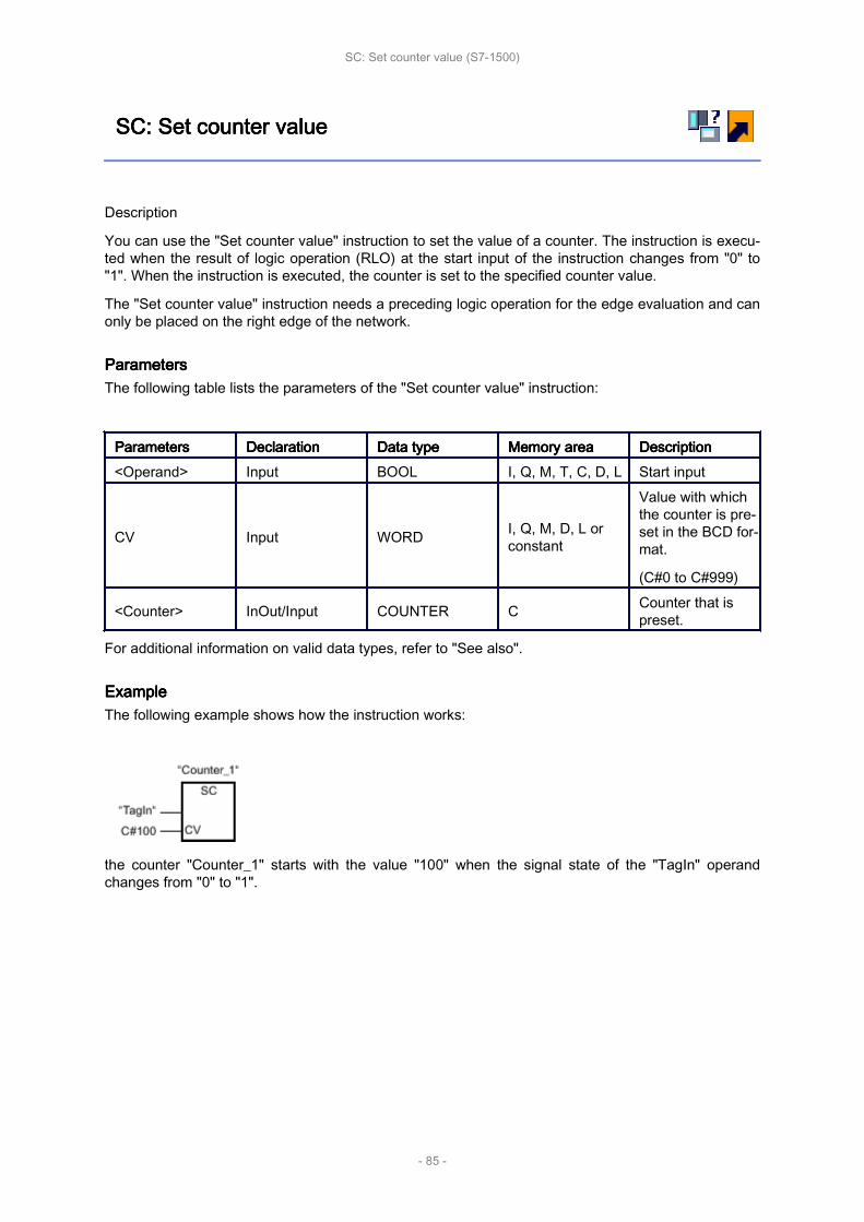
SC: SC: SC: SC: Set Set Set Set counter counter counter counter valuevaluevaluevalue
Description
You can use the "Set counter value" instruction to set the value of a counter. The instruction is execu‐ted when the result of logic operation (RLO) at the start input of the instruction changes from "0" to"1". When the instruction is executed, the counter is set to the specified counter value.
The "Set counter value" instruction needs a preceding logic operation for the edge evaluation and canonly be placed on the right edge of the network.
ParametersParametersParametersParametersThe following table lists the parameters of the "Set counter value" instruction:
ParametersParametersParametersParameters DeclarationDeclarationDeclarationDeclaration Data Data Data Data typetypetypetype Memory Memory Memory Memory areaareaareaarea DescriptionDescriptionDescriptionDescription<Operand> Input BOOL I, Q, M, T, C, D, L Start input
CV Input WORD I, Q, M, D, L orconstant
Value with whichthe counter is pre‐set in the BCD for‐mat.
(C#0 to C#999)
<Counter> InOut/Input COUNTER C Counter that ispreset.
For additional information on valid data types, refer to "See also".
ExampleExampleExampleExampleThe following example shows how the instruction works:
the counter "Counter_1" starts with the value "100" when the signal state of the "TagIn" operandchanges from "0" to "1".
SC: Set counter value (S7-1500)
- 85 -
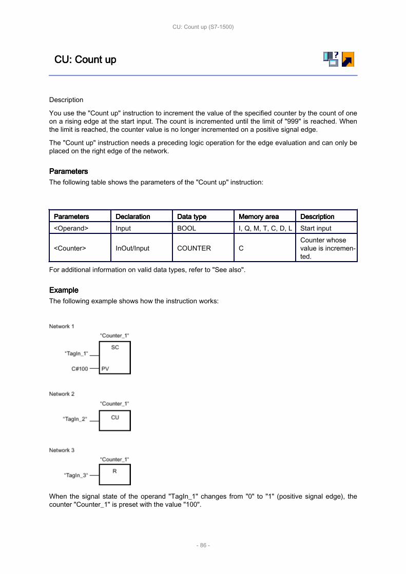
CU: CU: CU: CU: Count Count Count Count upupupup
Description
You use the "Count up" instruction to increment the value of the specified counter by the count of oneon a rising edge at the start input. The count is incremented until the limit of "999" is reached. Whenthe limit is reached, the counter value is no longer incremented on a positive signal edge.
The "Count up" instruction needs a preceding logic operation for the edge evaluation and can only beplaced on the right edge of the network.
ParametersParametersParametersParametersThe following table shows the parameters of the "Count up" instruction:
ParametersParametersParametersParameters DeclarationDeclarationDeclarationDeclaration Data Data Data Data typetypetypetype Memory Memory Memory Memory areaareaareaarea DescriptionDescriptionDescriptionDescription<Operand> Input BOOL I, Q, M, T, C, D, L Start input
<Counter> InOut/Input COUNTER CCounter whosevalue is incremen‐ted.
For additional information on valid data types, refer to "See also".
ExampleExampleExampleExampleThe following example shows how the instruction works:
When the signal state of the operand "TagIn_1" changes from "0" to "1" (positive signal edge), thecounter "Counter_1" is preset with the value "100".
CU: Count up (S7-1500)
- 86 -

The value of "Counter_1" is incremented by the count of one when the signal state of the "TagIn_2"operand changes from "0" to "1".
If the "TagIn_3" operand returns signal state "1", the value of "Counter_1" is reset to "0".
CU: Count up (S7-1500)
- 87 -

CD: CD: CD: CD: Count Count Count Count downdowndowndown
Description
You use the "Count down" instruction to decrement the value of the specified counter by the count ofone on a rising edge at the start input. The count is decremented until the limit of "0" is reached.When the limit is reached, the counter value is no longer changed on a positive signal edge.
The "Count down" instruction needs a preceding logic operation for the edge evaluation and can onlybe placed on the right edge of the network.
ParametersParametersParametersParametersThe following table shows the parameters of the "Count down" instruction:
ParametersParametersParametersParameters DeclarationDeclarationDeclarationDeclaration Data Data Data Data typetypetypetype Memory Memory Memory Memory areaareaareaarea DescriptionDescriptionDescriptionDescription<Operand> Input BOOL I, Q, M, T, C, D, L Start input
<Counter> InOut/Input COUNTER CCounter whosevalue is decre‐mented.
For additional information on valid data types, refer to "See also".
ExampleExampleExampleExampleThe following example shows how the instruction works:
When the signal state of the operand "TagIn_1" changes from "0" to "1" (positive signal edge), thecounter "Counter_1" is preset with the value "100".
CD: Count down (S7-1500)
- 88 -

The value of "Counter_1" is incremented by the count of one when the signal state of the "TagIn_2"operand changes from "0" to "1".
If the "TagIn_3" operand returns signal state "1", the value of "Counter_1" is reset to "0".
CD: Count down (S7-1500)
- 89 -

Comparator Comparator Comparator Comparator operationsoperationsoperationsoperations
This chapter contains the following information:
• CMP CMP CMP CMP ==: ==: ==: ==: Equal Equal Equal Equal (S7-1200, (S7-1200, (S7-1200, (S7-1200, S7-1500)S7-1500)S7-1500)S7-1500)
• CMP CMP CMP CMP <>: <>: <>: <>: Not Not Not Not equal equal equal equal (S7-1200, (S7-1200, (S7-1200, (S7-1200, S7-1500)S7-1500)S7-1500)S7-1500)
• CMP CMP CMP CMP >=: >=: >=: >=: Greater Greater Greater Greater or or or or equal equal equal equal (S7-1200, (S7-1200, (S7-1200, (S7-1200, S7-1500)S7-1500)S7-1500)S7-1500)
• CMP CMP CMP CMP <=: <=: <=: <=: Less Less Less Less or or or or equal equal equal equal (S7-1200, (S7-1200, (S7-1200, (S7-1200, S7-1500)S7-1500)S7-1500)S7-1500)
• CMP CMP CMP CMP >: >: >: >: Greater Greater Greater Greater than than than than (S7-1200, (S7-1200, (S7-1200, (S7-1200, S7-1500)S7-1500)S7-1500)S7-1500)
• CMP CMP CMP CMP <: <: <: <: Less Less Less Less than than than than (S7-1200, (S7-1200, (S7-1200, (S7-1200, S7-1500)S7-1500)S7-1500)S7-1500)
• IN_RANGE: IN_RANGE: IN_RANGE: IN_RANGE: Value Value Value Value within within within within range range range range (S7-1200, (S7-1200, (S7-1200, (S7-1200, S7-1500)S7-1500)S7-1500)S7-1500)
• OUT_RANGE: OUT_RANGE: OUT_RANGE: OUT_RANGE: Value Value Value Value outside outside outside outside range range range range (S7-1200, (S7-1200, (S7-1200, (S7-1200, S7-1500)S7-1500)S7-1500)S7-1500)
• OK: OK: OK: OK: Check Check Check Check validity validity validity validity (S7-1200, (S7-1200, (S7-1200, (S7-1200, S7-1500)S7-1500)S7-1500)S7-1500)
• NOT_OK: NOT_OK: NOT_OK: NOT_OK: Check Check Check Check invalidity invalidity invalidity invalidity (S7-1200, (S7-1200, (S7-1200, (S7-1200, S7-1500)S7-1500)S7-1500)S7-1500)
• VARIANT VARIANT VARIANT VARIANT instructions instructions instructions instructions (S7-1500)(S7-1500)(S7-1500)(S7-1500)
Comparator operations (S7-1200, S7-1500)
- 90 -
CMP CMP CMP CMP ==: ==: ==: ==: EqualEqualEqualEqual
Description
You can use the "Equal" instruction to query whether the value at input IN1 is equal to the value atinput IN2.
If the condition of the comparison is fulfilled, the instruction returns the result of logic operation (RLO)"1". If the comparison condition is not fulfilled, the instruction returns RLO "0".
The individual characters are compared by means of their code (for example, 'a' is greater than 'A')during the comparison of the strings. The comparison is performed from left to right. The first charac‐ter to be different decides the result of the comparison.
The following table lists examples of string comparisons:
IN1IN1IN1IN1 IN2IN2IN2IN2 RLO RLO RLO RLO of of of of the the the the instructioninstructioninstructioninstruction'AA' 'AA' 1'Hello World' 'HelloWorld' 0'AA' 'aa' 0
The "Equal" instruction also compares individual characters of a string. The number of the characterto be compared is specified in square brackets next to the operand name. "MyString[2]", for example,compares the second character of the "MyString" string.
If IEC check is enabled, the operands to be compared must be of the same data type. If IEC check isnot enabled, the width (length) of the operands must be the same. If the floating-point numbers arebeing compared, the operands to be compared must be of the same data type regardless of the IECcheck setting.
NoteNoteNoteNote
Comparison Comparison Comparison Comparison of of of of floating-point floating-point floating-point floating-point numbersnumbersnumbersnumbers
If you want to compare the data types REAL or LREAL, instead of the instruction "CMP ==: Equal",use the instruction "IN_RANGE: Value within range".
NoteNoteNoteNote
Comparison Comparison Comparison Comparison of of of of the the the the data data data data type type type type PORTPORTPORTPORT
To be able to compare the operands of the PORT data type with the "Equal" instruction, you needto select the WORD data type from the drop-down list of the instructions box.
ParametersParametersParametersParametersThe following table lists the parameters of the "Equal" instruction:
ParameterParameterParameterParameter DeclarationDeclarationDeclarationDeclaration Data Data Data Data typetypetypetype Memory Memory Memory Memory areaareaareaarea DescriptionDescriptionDescriptionDescriptionS7-1200S7-1200S7-1200S7-1200 S7-1500S7-1500S7-1500S7-1500
IN1 InputBit strings, in‐tegers, float‐ing-point num‐
Bit strings, in‐tegers, float‐ing-point num‐
I, Q, M, D, L, Por constant
First compari‐son value
CMP ==: Equal (S7-1200, S7-1500)
- 91 -

bers, characterstrings, TIME,DATE, TOD,DTL
bers, characterstrings, TIME,LTIME, DATE,TOD, LTOD,DTL, DT, LDT
IN2 Input
Bit strings, in‐tegers, float‐ing-point num‐bers, characterstrings, TIME,DATE, TOD,DTL
Bit strings, in‐tegers, float‐ing-point num‐bers, characterstrings, TIME,LTIME, DATE,TOD, LTOD,DTL, DT, LDT
I, Q, M, D, L, Por constant
Second valueto compare
You can select the data type of the instruction from the "<???>" drop-down list of the instruction box.
For additional information on valid data types, refer to "See also":
ExampleExampleExampleExampleThe following example shows how the instruction works:
The "TagOut" output is set when the following conditions are fulfilled:
• The operand "TagIn_1" has the signal state "1".
• The condition of the comparison instruction is fulfilled if "Tag_Value1" = "Tag_Value2".
CMP ==: Equal (S7-1200, S7-1500)
- 92 -
CMP CMP CMP CMP <>: <>: <>: <>: Not Not Not Not equalequalequalequal
Description
You can use the "Not equal" instruction to query whether the value at input IN1 is not equal to thevalue at input IN2.
If the condition of the comparison is fulfilled, the instruction returns the result of logic operation (RLO)"1". If the comparison condition is not fulfilled, the instruction returns RLO "0".
The individual characters are compared by means of their code (for example, 'a' is greater than 'A')during the comparison of the strings. The comparison is performed from left to right. The first charac‐ter to be different decides the result of the comparison.
The following table lists examples of string comparisons:
IN1IN1IN1IN1 IN2IN2IN2IN2 RLO RLO RLO RLO of of of of the the the the instructioninstructioninstructioninstruction'AA' 'aa' 1'Hello World' 'HelloWorld' 1'AA' 'AA' 0
The "Not equal" instruction also compares individual characters of a string. The number of the charac‐ter to be compared is specified in square brackets next to the operand name. "MyString[2]", for exam‐ple, compares the second character of the "MyString" string.
If IEC check is enabled, the operands to be compared must be of the same data type. If IEC check isnot enabled, the width (length) of the operands must be the same. If the floating-point numbers arebeing compared, the operands to be compared must be of the same data type regardless of the IECcheck setting.
NoteNoteNoteNote
Comparison Comparison Comparison Comparison of of of of the the the the data data data data type type type type PORTPORTPORTPORT
To be able to compare the operands of the PORT data type with the "Not equal" instruction, youneed to select the WORD data type from the drop-down list of the instructions box.
ParametersParametersParametersParametersThe following table lists the parameters of the "Not equal" instruction:
ParametersParametersParametersParameters DeclarationDeclarationDeclarationDeclaration Data Data Data Data typetypetypetype Memory Memory Memory Memory areaareaareaarea DescriptionDescriptionDescriptionDescriptionS7-1200S7-1200S7-1200S7-1200 S7-1500S7-1500S7-1500S7-1500
IN1 Input
Bit strings, in‐tegers, float‐ing-point num‐bers, characterstrings, TIME,DATE, TOD,DTL
Bit strings, in‐tegers, float‐ing-point num‐bers, characterstrings, TIME,LTIME, DATE,TOD, LTOD,DTL, DT, LDT
I, Q, M, D, L, Por constant
First compari‐son value
CMP <>: Not equal (S7-1200, S7-1500)
- 93 -

IN2 Input
Bit strings, in‐tegers, float‐ing-point num‐bers, characterstrings, TIME,DATE, TOD,DTL
Bit strings, in‐tegers, float‐ing-point num‐bers, characterstrings, TIME,LTIME, DATE,TOD, LTOD,DTL, DT, LDT
I, Q, M, D, L, Por constant
Second valueto compare
You can select the data type of the instruction from the "<???>" drop-down list of the instruction box.
For additional information on valid data types, refer to "See also".
ExampleExampleExampleExampleThe following example shows how the instruction works:
The "TagOut" output is set when the following conditions are fulfilled:
• The operand "TagIn_1" has the signal state "1".
• The condition of the comparison instruction is fulfilled if "Tag_Value1" <> "Tag_Value2".
CMP <>: Not equal (S7-1200, S7-1500)
- 94 -
CMP CMP CMP CMP >=: >=: >=: >=: Greater Greater Greater Greater or or or or equalequalequalequal
Description
You can use the "Greater or equal" instruction to query whether the value at input IN1 is greater orequal to the value at input IN2. Both values to be compared must be of the same data type.
If the condition of the comparison is fulfilled, the instruction returns the result of logic operation (RLO)"1". If the comparison condition is not fulfilled, the instruction returns RLO "0".
The individual characters are compared by means of their code (for example, 'a' is greater than 'A')during the comparison of the strings. The comparison is performed from left to right. The first charac‐ter to be different decides the result of the comparison. If the left part of the longer string is identical tothe shorter string, the longer string is considered greater.
The following table lists examples of string comparisons:
IN1IN1IN1IN1 IN2IN2IN2IN2 RLO RLO RLO RLO of of of of the the the the instructioninstructioninstructioninstruction'BB' 'AA' 1'AAA' 'AA' 1'Hello World' 'Hello World' 1'Hello World' 'HelloWorld' 0'AA' 'aa' 0'AAA' 'a' 0
The "Greater or equal" instruction also compares individual characters of a string. The number of thecharacter to be compared is specified in square brackets next to the operand name. "MyString[2]", forexample, compares the second character of the "MyString" string.
In comparing timer values, the RLO of the instruction is "1" if the timer at input IN1 is greater (morerecent) than or equal to the timer at input IN2.
ParametersParametersParametersParametersThe following table lists the parameters of the "Greater or equal" instruction:
ParametersParametersParametersParameters DeclarationDeclarationDeclarationDeclaration Data Data Data Data typetypetypetype Memory Memory Memory Memory areaareaareaarea DescriptionDescriptionDescriptionDescriptionS7-1200S7-1200S7-1200S7-1200 S7-1500S7-1500S7-1500S7-1500
IN1 Input
Integers, float‐ing-point num‐bers, characterstrings, TIME,DATE, TOD,DTL
Integers, float‐ing-point num‐bers, characterstrings, TIME,LTIME, DATE,TOD, LTOD,DTL, DT, LDT
I, Q, M, D, L, Por constant
First compari‐son value
IN2 Input
Integers, float‐ing-point num‐bers, characterstrings, TIME,
Integers, float‐ing-point num‐bers, characterstrings, TIME,LTIME, DATE,
I, Q, M, D, L, Por constant
Second valueto compare
CMP >=: Greater or equal (S7-1200, S7-1500)
- 95 -

DATE, TOD,DTL
TOD, LTOD,DTL, DT, LDT
You can select the data type of the instruction from the "<???>" drop-down list of the instruction box.
For additional information on valid data types, refer to "See also".
ExampleExampleExampleExampleThe following example shows how the instruction works:
The "TagOut" output is set when the following conditions are fulfilled:
• The operand "TagIn_1" has the signal state "1".
• The condition of the comparison instruction is fulfilled if "Tag_Value1" >= "Tag_Value2".
CMP >=: Greater or equal (S7-1200, S7-1500)
- 96 -

CMP CMP CMP CMP <=: <=: <=: <=: Less Less Less Less or or or or equalequalequalequal
Description
You can use the "Less or equal" instruction to query whether the value at input IN1 is less or equal tothe value at input IN2. Both values to be compared must be of the same data type.
If the condition of the comparison is fulfilled, the instruction returns the result of logic operation (RLO)"1". If the comparison condition is not fulfilled, the instruction returns RLO "0".
The individual characters are compared by means of their code (for example, 'a' is greater than 'A')during the comparison of the strings. The comparison is performed from left to right. The first charac‐ter to be different decides the result of the comparison. If the left part of the longer string is identical tothe shorter string, the shorter string is considered smaller.
The following table lists examples of string comparisons:
IN1IN1IN1IN1 IN2IN2IN2IN2 RLO RLO RLO RLO of of of of the the the the instructioninstructioninstructioninstruction'AA' 'aa' 1'AAA' 'a' 1'Hello World' 'Hello World' 1'HelloWorld' 'Hello World' 0'BB' 'AA' 0'AAA' 'AA' 0
The "Less or equal" instruction also compares individual characters of a string. The number of thecharacter to be compared is specified in square brackets next to the operand name. "MyString[2]", forexample, compares the second character of the "MyString" string.
In comparing timer values, the RLO of the instruction is "1" if the timer at input IN1 is smaller (lessrecent) than or equal to the timer at input IN2.
ParametersParametersParametersParametersThe following table lists the parameters of the "Less or equal" instruction:
ParametersParametersParametersParameters DeclarationDeclarationDeclarationDeclaration Data Data Data Data typetypetypetype Memory Memory Memory Memory areaareaareaarea DescriptionDescriptionDescriptionDescriptionS7-1200S7-1200S7-1200S7-1200 S7-1500S7-1500S7-1500S7-1500
IN1 Input
Integers, float‐ing-point num‐bers, characterstrings, TIME,DATE, TOD,DTL
Integers, float‐ing-point num‐bers, characterstrings, TIME,LTIME, DATE,TOD, LTOD,DTL, DT, LDT
I, Q, M, D, L, Por constant
First compari‐son value
IN2 Input
Integers, float‐ing-point num‐bers, characterstrings, TIME,
Integers, float‐ing-point num‐bers, characterstrings, TIME,LTIME, DATE,
I, Q, M, D, L, Por constant
Second valueto compare
CMP <=: Less or equal (S7-1200, S7-1500)
- 97 -

DATE, TOD,DTL
TOD, LTOD,DTL, DT, LDT
You can select the data type of the instruction from the "<???>" drop-down list of the instruction box.
For additional information on valid data types, refer to "See also".
ExampleExampleExampleExampleThe following example shows how the instruction works:
The "TagOut" output is set when the following conditions are fulfilled:
• The operand "TagIn_1" has the signal state "1".
• The condition of the comparison instruction is fulfilled if "Tag_Value1" <= "Tag_Value2".
CMP <=: Less or equal (S7-1200, S7-1500)
- 98 -

CMP CMP CMP CMP >: >: >: >: Greater Greater Greater Greater thanthanthanthan
Description
You can use the "Greater than" instruction to query whether the value at input IN1 is greater than thevalue at input IN2. Both values to be compared must be of the same data type.
If the condition of the comparison is fulfilled, the instruction returns the result of logic operation (RLO)"1". If the comparison condition is not fulfilled, the instruction returns RLO "0".
The individual characters are compared by means of their code (for example, 'a' is greater than 'A')during the comparison of the strings. The comparison is performed from left to right. The first charac‐ter to be different decides the result of the comparison. If the left part of the longer string is identical tothe shorter string, the longer string is considered greater.
The following table lists examples of string comparisons:
IN1IN1IN1IN1 IN2IN2IN2IN2 RLO RLO RLO RLO of of of of the the the the instructioninstructioninstructioninstruction'BB' 'AA' 1'AAA' 'AA' 1'AA' 'aa' 0'AAA' 'a' 0
The "Greater than" instruction also compares individual characters of a string. The number of thecharacter to be compared is specified in square brackets next to the operand name. "MyString[2]", forexample, compares the second character of the "MyString" string.
In comparing timer values, the RLO of the instruction is "1" if the timer at input IN1 is greater (morerecent) than the timer at input IN2.
ParametersParametersParametersParametersThe following table lists the parameters of the "Greater than" instruction:
ParametersParametersParametersParameters DeclarationDeclarationDeclarationDeclaration Data Data Data Data typetypetypetype Memory Memory Memory Memory areaareaareaarea DescriptionDescriptionDescriptionDescriptionS7-1200S7-1200S7-1200S7-1200 S7-1500S7-1500S7-1500S7-1500
IN1 Input
Integers, float‐ing-point num‐bers, characterstrings, TIME,DATE, TOD,DTL
Integers, float‐ing-point num‐bers, characterstrings, TIME,LTIME, DATE,TOD, LTOD,DTL, DT, LDT
I, Q, M, D, L, Por constant
First compari‐son value
IN2 Input
Integers, float‐ing-point num‐bers, characterstrings, TIME,DATE, TOD,DTL
Integers, float‐ing-point num‐bers, characterstrings, TIME,LTIME, DATE,TOD, LTOD,DTL, DT, LDT
I, Q, M, D, L, Por constant
Second valueto compare
CMP >: Greater than (S7-1200, S7-1500)
- 99 -

You can select the data type of the instruction from the "<???>" drop-down list of the instruction box.
For additional information on valid data types, refer to "See also".
ExampleExampleExampleExampleThe following example shows how the instruction works:
The "TagOut" output is set when the following conditions are fulfilled:
• The operand "TagIn_1" has the signal state "1".
• The condition of the comparison instruction is fulfilled if "Tag_Value1" > "Tag_Value2".
CMP >: Greater than (S7-1200, S7-1500)
- 100 -
CMP CMP CMP CMP <: <: <: <: Less Less Less Less thanthanthanthan
Description
You can use the "Less than" instruction to query whether the value at input IN1 is less than the valueat input IN2. Both values to be compared must be of the same data type.
If the condition of the comparison is fulfilled, the instruction returns the result of logic operation (RLO)"1". If the comparison condition is not fulfilled, the instruction returns RLO "0".
The individual characters are compared by means of their code (for example, 'a' is greater than 'A')during the comparison of the strings. The comparison is performed from left to right. The first charac‐ter to be different decides the result of the comparison. If the left part of the longer string is identical tothe shorter string, the shorter string is considered smaller.
The following table lists examples of string comparisons:
<Operand1><Operand1><Operand1><Operand1> <Operand2><Operand2><Operand2><Operand2> RLO RLO RLO RLO of of of of the the the the instructioninstructioninstructioninstruction'AA' 'aa' 1'AAA' 'a' 1'BB' 'AA' 0'AAA' 'AA' 0
The "Less than" instruction also compares individual characters of a string. The number of the charac‐ter to be compared is specified in square brackets next to the operand name. "MyString[2]", for exam‐ple, compares the second character of the "MyString" string.
In comparing timer values, the RLO of the instruction is "1" if the timer at input IN1 is less (less recent)than the timer at input IN2 .
ParametersParametersParametersParametersThe following table lists the parameters of the "Less than" instruction:
ParametersParametersParametersParameters DeclarationDeclarationDeclarationDeclaration Data Data Data Data typetypetypetype Memory Memory Memory Memory areaareaareaarea DescriptionDescriptionDescriptionDescriptionS7-1200S7-1200S7-1200S7-1200 S7-1500S7-1500S7-1500S7-1500
IN1 Input
Integers, float‐ing-point num‐bers, characterstrings, TIME,DATE, TOD,DTL
Integers, float‐ing-point num‐bers, characterstrings, TIME,LTIME, DATE,TOD, LTOD,DTL, DT, LDT
I, Q, M, D, L, Por constant
First compari‐son value
IN2 Input
Integers, float‐ing-point num‐bers, characterstrings, TIME,DATE, TOD,DTL
Integers, float‐ing-point num‐bers, characterstrings, TIME,LTIME, DATE,TOD, LTOD,DTL, DT, LDT
I, Q, M, D, L, Por constant
Second valueto compare
CMP <: Less than (S7-1200, S7-1500)
- 101 -

You can select the data type of the instruction from the "<???>" drop-down list of the instruction box.
For additional information on valid data types, refer to "See also".
ExampleExampleExampleExampleThe following example shows how the instruction works:
The "TagOut" output is set when the following conditions are fulfilled:
• The operand "TagIn_1" has the signal state "1".
• The condition of the comparison instruction is fulfilled if "Tag_Value1" < "Tag_Value2".
CMP <: Less than (S7-1200, S7-1500)
- 102 -

Math Math Math Math functionsfunctionsfunctionsfunctions
This chapter contains the following information:
• CALCULATE: CALCULATE: CALCULATE: CALCULATE: Calculate Calculate Calculate Calculate (S7-1200, (S7-1200, (S7-1200, (S7-1200, S7-1500)S7-1500)S7-1500)S7-1500)
• ADD: ADD: ADD: ADD: Add Add Add Add (S7-1200, (S7-1200, (S7-1200, (S7-1200, S7-1500)S7-1500)S7-1500)S7-1500)
• SUB: SUB: SUB: SUB: Subtract Subtract Subtract Subtract (S7-1200, (S7-1200, (S7-1200, (S7-1200, S7-1500)S7-1500)S7-1500)S7-1500)
• MUL: MUL: MUL: MUL: Multiply Multiply Multiply Multiply (S7-1200, (S7-1200, (S7-1200, (S7-1200, S7-1500)S7-1500)S7-1500)S7-1500)
• DIV: DIV: DIV: DIV: Divide Divide Divide Divide (S7-1200, (S7-1200, (S7-1200, (S7-1200, S7-1500)S7-1500)S7-1500)S7-1500)
• MOD: MOD: MOD: MOD: Return Return Return Return remainder remainder remainder remainder of of of of division division division division (S7-1200, (S7-1200, (S7-1200, (S7-1200, S7-1500)S7-1500)S7-1500)S7-1500)
• NEG: NEG: NEG: NEG: Create Create Create Create twos twos twos twos complement complement complement complement (S7-1200, (S7-1200, (S7-1200, (S7-1200, S7-1500)S7-1500)S7-1500)S7-1500)
• INC: INC: INC: INC: Increment Increment Increment Increment (S7-1200, (S7-1200, (S7-1200, (S7-1200, S7-1500)S7-1500)S7-1500)S7-1500)
• DEC: DEC: DEC: DEC: Decrement Decrement Decrement Decrement (S7-1200, (S7-1200, (S7-1200, (S7-1200, S7-1500)S7-1500)S7-1500)S7-1500)
• ABS: ABS: ABS: ABS: Form Form Form Form absolute absolute absolute absolute value value value value (S7-1200, (S7-1200, (S7-1200, (S7-1200, S7-1500)S7-1500)S7-1500)S7-1500)
• MIN: MIN: MIN: MIN: Get Get Get Get minimum minimum minimum minimum (S7-1200, (S7-1200, (S7-1200, (S7-1200, S7-1500)S7-1500)S7-1500)S7-1500)
• MAX: MAX: MAX: MAX: Get Get Get Get maximum maximum maximum maximum (S7-1200, (S7-1200, (S7-1200, (S7-1200, S7-1500)S7-1500)S7-1500)S7-1500)
• LIMIT: LIMIT: LIMIT: LIMIT: Set Set Set Set limit limit limit limit value value value value (S7-1200, (S7-1200, (S7-1200, (S7-1200, S7-1500)S7-1500)S7-1500)S7-1500)
• SQR: SQR: SQR: SQR: Form Form Form Form square square square square (S7-1200, (S7-1200, (S7-1200, (S7-1200, S7-1500)S7-1500)S7-1500)S7-1500)
• SQRT: SQRT: SQRT: SQRT: Form Form Form Form square square square square root root root root (S7-1200, (S7-1200, (S7-1200, (S7-1200, S7-1500)S7-1500)S7-1500)S7-1500)
• LN: LN: LN: LN: Form Form Form Form natural natural natural natural logarithm logarithm logarithm logarithm (S7-1200, (S7-1200, (S7-1200, (S7-1200, S7-1500)S7-1500)S7-1500)S7-1500)
• EXP: EXP: EXP: EXP: Form Form Form Form exponential exponential exponential exponential value value value value (S7-1200, (S7-1200, (S7-1200, (S7-1200, S7-1500)S7-1500)S7-1500)S7-1500)
• SIN: SIN: SIN: SIN: Form Form Form Form sine sine sine sine value value value value (S7-1200, (S7-1200, (S7-1200, (S7-1200, S7-1500)S7-1500)S7-1500)S7-1500)
• COS: COS: COS: COS: Form Form Form Form cosine cosine cosine cosine value value value value (S7-1200, (S7-1200, (S7-1200, (S7-1200, S7-1500)S7-1500)S7-1500)S7-1500)
• TAN: TAN: TAN: TAN: Form Form Form Form tangent tangent tangent tangent value value value value (S7-1200, (S7-1200, (S7-1200, (S7-1200, S7-1500)S7-1500)S7-1500)S7-1500)
• ASIN: ASIN: ASIN: ASIN: Form Form Form Form arcsine arcsine arcsine arcsine value value value value (S7-1200, (S7-1200, (S7-1200, (S7-1200, S7-1500)S7-1500)S7-1500)S7-1500)
• ACOS: ACOS: ACOS: ACOS: Form Form Form Form arccosine arccosine arccosine arccosine value value value value (S7-1200, (S7-1200, (S7-1200, (S7-1200, S7-1500)S7-1500)S7-1500)S7-1500)
• ATAN: ATAN: ATAN: ATAN: Form Form Form Form arctangent arctangent arctangent arctangent value value value value (S7-1200, (S7-1200, (S7-1200, (S7-1200, S7-1500)S7-1500)S7-1500)S7-1500)
• FRAC: FRAC: FRAC: FRAC: Return Return Return Return fraction fraction fraction fraction (S7-1200, (S7-1200, (S7-1200, (S7-1200, S7-1500)S7-1500)S7-1500)S7-1500)
• EXPT: EXPT: EXPT: EXPT: Exponentiate Exponentiate Exponentiate Exponentiate (S7-1200, (S7-1200, (S7-1200, (S7-1200, S7-1500)S7-1500)S7-1500)S7-1500)
Math functions (S7-1200, S7-1500)
- 103 -

CALCULATE: CALCULATE: CALCULATE: CALCULATE: CalculateCalculateCalculateCalculate
Description
The "Calculate" instruction is used to define and execute an expression for the calculation of mathe‐matical operations or complex logic operations depending on the selected data type.
You can select the data type of the instruction from the "<???>" drop-down list of the instruction box.Depending on the selected data type, you can combine the functionality of specific instructions to exe‐cute a complex calculation. The expression to be calculated is specified via a dialog you can open viathe "Calculator" icon at the top of the instruction box. The expression can contain the names of theinput parameters and the syntax of the instructions. It is not permitted to specify operand names oroperand addresses.
In its initial state, the instruction box contains at least 2 inputs (IN1 and IN2). The number of inputscan be extended. The inserted inputs are numbered in ascending order in the box.
The values of the inputs are use to execute the specified expression. Not all defined inputs have to beused in the expression. The result of the instruction is transferred to the box output OUT.
NoteNoteNoteNoteIf one of the mathematical operations fails in the expression, then no result is transferred to theOUT output and the ENO enable output has the signal state "1".
If, in the expression, you use inputs that are not available in the box, these inputs are automaticallyinserted. Provided that there are no gaps in the numbering of the inputs that are to be newly definedin the expression. You cannot, for example, use the input IN4 in the expression if the input IN3 is notdefined.
Enable output ENO has the signal state "0" if one of the following conditions is fulfilled:
• Enable input EN has the signal state "0".
• The result or an interim result of the "Calculate" instruction is outside the range permitted for thedata type specified at output OUT.• A floating-point number has an invalid value.
• An error occurred during the execution of one of the instructions specified in the expression.
The following table shows the instructions that, depending on the selected data type, can be com‐bined and executed in the expression of the "Calculate" instruction:
Data Data Data Data typetypetypetype InstructionInstructionInstructionInstruction SyntaxSyntaxSyntaxSyntax ExampleExampleExampleExample
Bit strings
AND: AND logic operation AND
IN1 AND IN2 ORIN3
OR: OR logic operation ORXOR: EXCLUSIVE OR logic operation XORINV: Create ones complement NOT
SWAP: Swap 1) SWAP
Integers
ADD: Add + (IN1 + IN2) * IN3;
(ABS(IN2)) *(ABS(IN1))
SUB: Subtract -MUL: Multiply *
CALCULATE: Calculate (S7-1200, S7-1500)
- 104 -

DIV: Divide /MOD: Return remainder of division MODINV: Create ones complement NOTNEG: Create twos complement -(in1)ABS: Form absolute value ABS( )
Floating-pointnumbers
ADD: Add +
((SIN(IN2) *SIN(IN2) +(SIN(IN3) *SIN(IN3)) / IN3));
(SQR(SIN(IN2))+(SQR(COS(IN3))/ IN2))
SUB: Subtract -MUL: Multiply *DIV: Divide /EXPT: Exponentiate **ABS: Form absolute value ABS( )SQR: Form square SQR( )SQRT: Form square root SQRT( )LN: Form natural logarithm LN( )EXP: Form exponential value EXP( )FRAC: Return fraction FRAC( )SIN: Form sine value SIN( )COS: Form cosine value COS( )TAN: Form tangent value TAN( )ASIN: Form arcsine value ASIN( )ACOS: Form arccosine value ACOS( )ATAN: Form arctangent value ATAN( )NEG: Create twos complement -(in1)TRUNC: Truncate numerical value TRUNC( )ROUND: Round numerical value ROUND( )CEIL: Generate next higher integer fromfloating-point number CEIL( )
FLOOR: Generate next lower integerfrom floating-point number FLOOR( )
1) Not possible for data type BYTE.
ParametersParametersParametersParametersThe following table shows the parameters of the instruction "Calculate":
ParametersParametersParametersParameters DeclarationDeclarationDeclarationDeclaration Data Data Data Data typetypetypetype Memory Memory Memory Memory areaareaareaarea DescriptionDescriptionDescriptionDescriptionS7-1200S7-1200S7-1200S7-1200 S7-1500S7-1500S7-1500S7-1500
EN Input BOOL I, Q, M, D, L I, Q, M, D, L,T, C Enable input
ENO Output BOOL I, Q, M, D, L I, Q, M, D, L Enable output
IN1 Input Bit strings, in‐tegers, float‐
I, Q, M, D, L, Por constant
I, Q, M, D, L, Por constant
First availableinput
CALCULATE: Calculate (S7-1200, S7-1500)
- 105 -

ing-point num‐bers
IN2 Input
Bit strings, in‐tegers, float‐ing-point num‐bers
I, Q, M, D, L, Por constant
I, Q, M, D, L, Por constant
Second availa‐ble input
INn Input
Bit strings, in‐tegers, float‐ing-point num‐bers
I, Q, M, D, L, Por constant
I, Q, M, D, L, Por constant
Additionally in‐serted inputs
OUT Output
Bit strings, in‐tegers, float‐ing-point num‐bers
I, Q, M, D, L, P I, Q, M, D, L, P
Output towhich the endresult is to betransferred.
For additional information on valid data types, refer to "See also".
ExampleExampleExampleExampleThe following example shows how the instruction works:
The following table shows how the instruction works using specific operand values:
ParametersParametersParametersParameters OperandOperandOperandOperand ValueValueValueValueIN1 Tag_Value_1 4IN2 Tag_Value_2 4IN3 Tag_Value_3 3IN4 Tag_Value_4 2OUT Tag_Result 12
The "Calculate" instruction is executed when input "Tag_Input" has the signal state "1". The value ofoperand "Tag_Value_1" is added to the value of operand "Tag_Value_2". The sum is multiplied withthe value of the operand "Tag_Value_3". The product is divided by the value of the operand "Tag_Val‐ue_4". The quotient is transferred as end result to the operand "Tag_Result" at the OUT output of theinstruction. If no errors occur during the execution of the individual instructions, output ENO and theoperand "Tag_Output" are set to "1".
CALCULATE: Calculate (S7-1200, S7-1500)
- 106 -

ADD: ADD: ADD: ADD: AddAddAddAdd
Description
You can use the "Add" instruction to add the value at input IN1 to the value at input IN2 and query thesum at output OUT (OUT := IN1+IN2).
In its initial state the instruction box contains at least 2 inputs (IN1 and IN2). The number of inputs canbe extended. The inserted inputs are numbered in ascending order in the box. During the execution ofthe instruction, the values of all available input parameters are added. The sum is stored at outputOUT.
Enable output ENO has the signal state "0" if one of the following conditions applies:
• Enable input EN has the signal state "0".
• The result of the instruction is outside the range permitted for the data type specified at outputOUT.• A floating-point number has an invalid value.
ParametersParametersParametersParametersThe following table shows the parameters of the instruction "Add":
ParametersParametersParametersParameters DeclarationDeclarationDeclarationDeclaration Data Data Data Data typetypetypetype Memory Memory Memory Memory areaareaareaarea DescriptionDescriptionDescriptionDescriptionS7-1200S7-1200S7-1200S7-1200 S7-1500S7-1500S7-1500S7-1500
EN Input BOOL I, Q, M, D, L I, Q, M, D, L,T, C Enable input
ENO Output BOOL I, Q, M, D, L I, Q, M, D, L Enable output
IN1 InputIntegers, float‐ing-point num‐bers
I, Q, M, D, L, Por constant
I, Q, M, D, L, Por constant
First number tobe added
IN2 InputIntegers, float‐ing-point num‐bers
I, Q, M, D, L, Por constant
I, Q, M, D, L, Por constant
Second num‐ber to be add‐ed
INn InputIntegers, float‐ing-point num‐bers
I, Q, M, D, L, Por constant
I, Q, M, D, L, Por constant
Optional inputvalues, whichare added.
OUT OutputIntegers, float‐ing-point num‐bers
I, Q, M, D, L, P I, Q, M, D, L, P Sum
You can select the data type of the instruction from the "<???>" drop-down list of the instruction box.
For additional information on valid data types, refer to "See also":
ExampleExampleExampleExampleThe following example shows how the instruction works:
ADD: Add (S7-1200, S7-1500)
- 107 -
If the operand "TagIn" has the signal state "1", the "Add" instruction is executed. The value of operand"Tag_Value1" is added to the value of operand "Tag_Value2". The result of the addition is stored inthe operand "Tag_Result". If the instruction is executed without errors, the ENO enable output has thesignal state "1" and the "TagOut" output is set.
ADD: Add (S7-1200, S7-1500)
- 108 -

SUB: SUB: SUB: SUB: SubtractSubtractSubtractSubtract
Description
You can use the "Subtract" instruction to subtract the value at input IN2 from the value at input IN1and query the difference at output OUT (OUT := IN1-IN2).
Enable output ENO has the signal state "0" if one of the following conditions applies:
• Enable input EN has the signal state "0".
• The result of the instruction is outside the range permitted for the data type specified at outputOUT.• A floating-point number has an invalid value.
ParametersParametersParametersParametersThe following table shows the parameters of the instruction "Subtract":
ParametersParametersParametersParameters DeclarationDeclarationDeclarationDeclaration Data Data Data Data typetypetypetype Memory Memory Memory Memory areaareaareaarea DescriptionDescriptionDescriptionDescriptionS7-1200S7-1200S7-1200S7-1200 S7-1500S7-1500S7-1500S7-1500
EN Input BOOL I, Q, M, D, L I, Q, M, D, L,T, C Enable input
ENO Output BOOL I, Q, M, D, L I, Q, M, D, L Enable output
IN1 InputIntegers, float‐ing-point num‐bers
I, Q, M, D, L, Por constant
I, Q, M, D, L, Por constant Minuend
IN2 InputIntegers, float‐ing-point num‐bers
I, Q, M, D, L, Por constant
I, Q, M, D, L, Por constant Subtrahend
OUT OutputIntegers, float‐ing-point num‐bers
I, Q, M, D, L, P I, Q, M, D, L, P Difference
You can select the data type of the instruction from the "<???>" drop-down list of the instruction box.
For additional information on valid data types, refer to "See also".
ExampleExampleExampleExampleThe following example shows how the instruction works:
SUB: Subtract (S7-1200, S7-1500)
- 109 -

If the operand "TagIn" has the signal state "1", the "Subtract" instruction is executed. The value of op‐erand "Tag_Value2" is subtracted from the value of operand "Tag_Value1". The result of the subtrac‐tion is stored in the operand "Tag_Result". If the instruction is executed without errors, the ENO ena‐ble output has the signal state "1" and the "TagOut" output is set.
SUB: Subtract (S7-1200, S7-1500)
- 110 -

MUL: MUL: MUL: MUL: MultiplyMultiplyMultiplyMultiply
Description
You can use the "Multiply" instruction to multiply the value at input IN1 with the value at input IN2 andquery the total at output OUT (OUT := IN1*IN2).
In its initial state the instruction box contains at least 2 inputs (IN1 and IN2). The number of inputs canbe extended. The inserted inputs are numbered in ascending order in the box. When the instruction isexecuted, the values of all available input parameters are multiplied. The product is stored at the OUToutput.
Enable output ENO has the signal state "0" if one of the following conditions applies:
• Enable input EN has the signal state "0".
• The result is outside the range permitted for the data type specified at output OUT.
• A floating-point number has an invalid value.
ParametersParametersParametersParametersThe following table shows the parameters of the instruction "Multiply":
ParametersParametersParametersParameters DeclarationDeclarationDeclarationDeclaration Data Data Data Data typetypetypetype Memory Memory Memory Memory areaareaareaarea DescriptionDescriptionDescriptionDescriptionS7-1200S7-1200S7-1200S7-1200 S7-1500S7-1500S7-1500S7-1500
EN Input BOOL I, Q, M, D, L I, Q, M, D, L,T, C Enable input
ENO Output BOOL I, Q, M, D, L I, Q, M, D, L Enable output
IN1 InputIntegers, float‐ing-point num‐bers
I, Q, M, D, L, Por constant
I, Q, M, D, L, Por constant
First value formultiplication
IN2 InputIntegers, float‐ing-point num‐bers
I, Q, M, D, L, Por constant
I, Q, M, D, L, Por constant
Second valuefor multiplica‐tion
INn InputIntegers, float‐ing-point num‐bers
I, Q, M, D, L, Por constant
I, Q, M, D, L, Por constant
Optional inputvalues, whichare multiplied.
OUT OutputIntegers, float‐ing-point num‐bers
I, Q, M, D, L, P I, Q, M, D, L, P Product
You can select the data type of the instruction from the "<???>" drop-down list of the instruction box.
For additional information on valid data types, refer to "See also".
ExampleExampleExampleExampleThe following example shows how the instruction works:
MUL: Multiply (S7-1200, S7-1500)
- 111 -
If the operand "TagIn" has the signal state "1", the "Multiply" instruction is executed. The value of op‐erand "Tag_Value1" is multiplied with the value of operand "Tag_Value2". The result of the multiplica‐tion is stored in the operand "Tag_Result". If the instruction is executed without errors, the ENO ena‐ble output has the signal state "1" and the "TagOut" output is set.
MUL: Multiply (S7-1200, S7-1500)
- 112 -

DIV: DIV: DIV: DIV: DivideDivideDivideDivide
Description
You can use the "Divide" instruction to divide the value at input IN1 by the value at input IN2 andquery the quotient at output OUT (OUT := IN1/IN2).
Enable output ENO has the signal state "0" if one of the following conditions applies:
• Enable input EN has the signal state "0".
• The result of the instruction is outside the range permitted for the data type specified at outputOUT.• A floating-point number has an invalid value.
ParametersParametersParametersParametersThe following table shows the parameters of the instruction "Divide":
ParametersParametersParametersParameters DeclarationDeclarationDeclarationDeclaration Data Data Data Data typetypetypetype Memory Memory Memory Memory areaareaareaarea DescriptionDescriptionDescriptionDescriptionS7-1200S7-1200S7-1200S7-1200 S7-1500S7-1500S7-1500S7-1500
EN Input BOOL I, Q, M, D, L I, Q, M, D, L,T, C Enable input
ENO Output BOOL I, Q, M, D, L I, Q, M, D, L Enable output
IN1 InputIntegers, float‐ing-point num‐bers
I, Q, M, D, L, Por constant
I, Q, M, D, L, Por constant Dividend
IN2 InputIntegers, float‐ing-point num‐bers
I, Q, M, D, L, Por constant
I, Q, M, D, L, Por constant Divisor
OUT OutputIntegers, float‐ing-point num‐bers
I, Q, M, D, L, P I, Q, M, D, L, P Quotient value
You can select the data type of the instruction from the "<???>" drop-down list of the instruction box.
For additional information on valid data types, refer to "See also".
ExampleExampleExampleExampleThe following example shows how the instruction works:
DIV: Divide (S7-1200, S7-1500)
- 113 -
If the operand "TagIn" has the signal state "1", the "Divide" instruction is executed. The value of oper‐and "Tag_Value1" is divided by the value of operand "Tag_Value2". The result of the division is storedin the operand "Tag_Result". If the instruction is executed without errors, the ENO enable output hasthe signal state "1" and the "TagOut" output is set.
DIV: Divide (S7-1200, S7-1500)
- 114 -
NEG: NEG: NEG: NEG: Create Create Create Create twos twos twos twos complementcomplementcomplementcomplement
Description
You can use the "Create twos complement" instruction to change the sign of the value at input IN andquery the result at output OUT. If there is a positive value at input IN, for example, the negative equiv‐alent of this value is sent to output OUT.
Enable output ENO has the signal state "0" if one of the following conditions applies:
• Enable input EN has the signal state "0".
• The result of the instruction is outside the range permitted for the data type specified at outputOUT.• A floating-point number has an invalid value.
ParametersParametersParametersParametersThe following table shows the parameters of the "Create twos complement" instruction:
ParametersParametersParametersParameters DeclarationDeclarationDeclarationDeclaration Data Data Data Data typetypetypetype Memory Memory Memory Memory areaareaareaarea DescriptionDescriptionDescriptionDescriptionS7-1200S7-1200S7-1200S7-1200 S7-1500S7-1500S7-1500S7-1500 S7-1200S7-1200S7-1200S7-1200 S7-1500S7-1500S7-1500S7-1500
EN Input BOOL BOOL I, Q, M, D, L I, Q, M, D, L,T, C Enable input
ENO Output BOOL BOOL I, Q, M, D, L I, Q, M, D, L Enable out‐put
IN Input
SINT, INT,DINT, Float‐ing-pointnumbers
SINT, INT,DINT, LINT,Floating-point num‐bers
I, Q, M, D, L,P or con‐stant
I, Q, M, D, L,P or con‐stant
Input value
OUT Output
SINT, INT,DINT, Float‐ing-pointnumbers
SINT, INT,DINT, LINT,Floating-point num‐bers
I, Q, M, D, L,P
I, Q, M, D, L,P
Twos com‐plement ofthe inputvalue
You can select the data type of the instruction from the "<???>" drop-down list of the instruction box.
For additional information on valid data types, refer to "See also".
ExampleExampleExampleExampleThe following example shows how the instruction works:
NEG: Create twos complement (S7-1200, S7-1500)
- 115 -

If the operand "TagIn" has the signal state "1", the "Create twos complement" instruction is executed.The sign of the value at input "TagIn_Value" is changed and the result is stored at output "Tag‐Out_Value". If the instruction is executed without errors, the ENO enable output has the signal state"1" and the "TagOut" output is set.
NEG: Create twos complement (S7-1200, S7-1500)
- 116 -

INC: INC: INC: INC: IncrementIncrementIncrementIncrement
Description
You can use the "Increment" instruction to change the value of the operand at parameter IN/OUT tothe next higher value and query the result.
Enable output ENO has the signal state "0" if one of the following conditions applies:
• Enable input EN has the signal state "0".
• A floating-point number has an invalid value.
ParametersParametersParametersParametersThe following table shows the parameters of the "Increment" instruction:
ParametersParametersParametersParameters DeclarationDeclarationDeclarationDeclaration Data Data Data Data typetypetypetype Memory Memory Memory Memory areaareaareaarea DescriptionDescriptionDescriptionDescriptionS7-1200S7-1200S7-1200S7-1200 S7-1500S7-1500S7-1500S7-1500
EN Input BOOL I, Q, M, D, L I, Q, M, D, L,T, C Enable input
ENO Output BOOL I, Q, M, D, L I, Q, M, D, L Enable output
IN/OUT InOut Integers I, Q, M, D, L I, Q, M, D, L Value to be in‐cremented.
You can select the data type of the instruction from the "<???>" drop-down list of the instruction box.
For additional information on valid data types, refer to "See also".
ExampleExampleExampleExampleThe following example shows how the instruction works:
If the operands TagIn_1 and TagIn_2 have the signal state "1", the value of the operand "Tag_InOut"is incremented by one and the output "TagOut" is set.
INC: Increment (S7-1200, S7-1500)
- 117 -

DEC: DEC: DEC: DEC: DecrementDecrementDecrementDecrement
Description
You can use the "Decrement" instruction to change the value of the operand at parameter IN/OUT tothe next lower value and query the result.
Enable output ENO has the signal state "0" if one of the following conditions applies:
• Enable input EN has the signal state "0".
• A floating-point number has an invalid value.
ParametersParametersParametersParametersThe following table shows the parameters of the instruction "Decrement":
ParametersParametersParametersParameters DeclarationDeclarationDeclarationDeclaration Data Data Data Data typetypetypetype Memory Memory Memory Memory areaareaareaarea DescriptionDescriptionDescriptionDescriptionS7-1200S7-1200S7-1200S7-1200 S7-1500S7-1500S7-1500S7-1500
EN Input BOOL I, Q, M, D, L I, Q, M, D, L,T, C Enable input
ENO Output BOOL I, Q, M, D, L I, Q, M, D, L Enable output
IN/OUT InOut Integers I, Q, M, D, L I, Q, M, D, L Value to bedecremented.
You can select the data type of the instruction from the "<???>" drop-down list of the instruction box.
For additional information on valid data types, refer to "See also".
ExampleExampleExampleExampleThe following example shows how the instruction works:
If the operands "TagIn_1" and "TagIn_2" have the signal state "1", the value of the operand "Tag_In‐Out" is decremented by one and the output "TagOut" is set.
DEC: Decrement (S7-1200, S7-1500)
- 118 -

MIN: MIN: MIN: MIN: Get Get Get Get minimumminimumminimumminimum
Description
The "Get minimum" instruction compares the values at the available inputs and writes the lowest val‐ue to the OUT output. The number of inputs can be expanded at the instruction box by additional in‐puts. The inputs are numbered in ascending order in the box.
In its initial state the instruction contains at least two inputs (IN1 and IN2) and no more than 100 in‐puts.
The ENO enable output has the signal state "0" if one of the following conditions is fulfilled:
• Enable input EN has the signal state "0".
• The implicit conversion of the data types fails during execution of the instruction.
• A floating-point number has an invalid value.
ParametersParametersParametersParametersThe following table shows the parameters of the "Get minimum" instruction:
ParameterParameterParameterParameter DeclarationDeclarationDeclarationDeclaration Data Data Data Data typetypetypetype Memory Memory Memory Memory areaareaareaarea DescriptionDescriptionDescriptionDescriptionS7-1200S7-1200S7-1200S7-1200 S7-1500S7-1500S7-1500S7-1500 S7-1200S7-1200S7-1200S7-1200 S7-1500S7-1500S7-1500S7-1500
EN Input BOOL BOOL I, Q, M, D, L I, Q, M, D, L,T, C Enable input
ENO Output BOOL BOOL I, Q, M, D, L I, Q, M, D, L Enable out‐put
IN1 Input
Integers,floating-point num‐bers,TIME,TOD,DATE
Integers,floating-pointnumbers,TIME,LTIME,TOD, LTOD,DATE, LDT
I, Q, M, D, L,P or con‐stant
I, Q, M, D, L,P or con‐stant
First inputvalue
IN2 Input
Integers,floating-point num‐bers,TIME,TOD,DATE
Integers,floating-pointnumbers,TIME,LTIME,TOD, LTOD,DATE, LDT
I, Q, M, D, L,P or con‐stant
I, Q, M, D, L,P or con‐stant
Second inputvalue
INn Input
Integers,floating-point num‐bers,TIME,TOD,DATE
Integers,floating-pointnumbers,TIME,LTIME,TOD, LTOD,DATE, LDT
I, Q, M, D, L,P or con‐stant
I, Q, M, D, L,P or con‐stant
Additionallyinserted in‐puts whosevalues are tobe compared
OUT Output Integers,floating-
Integers,floating-point
I, Q, M, D, L,P
I, Q, M, D, L,P Result
MIN: Get minimum (S7-1200, S7-1500)
- 119 -

point num‐bers,TIME,TOD,DATE
numbers,TIME,LTIME,TOD, LTOD,DATE, LDT
The data types TOD, LTOD, DATE, and LDT can only be used if the IEC test is not enabled.
You can select the data type of the instruction from the "<???>" drop-down list of the instruction box.
For additional information on valid data types, refer to "See also".
ExampleExampleExampleExampleThe following example shows how the instruction works:
The following table shows how the instruction works using specific operand values:
ParameterParameterParameterParameter OperandOperandOperandOperand ValueValueValueValueIN1 TagIn_Value1 12222IN2 TagIn_Value2 14444IN3 TagIn_Value3 13333OUT TagOut_Value 12222
If the "TagIn_1" and "TagIn_2" operands have signal state "1", the "Get minimum" instruction is exe‐cuted. The instruction compares the values of the specified operands and copies the lowest value("TagIn_Value1") to output "TagOut_Value". If the instruction is executed without errors, the output"TagOut" is set.
MIN: Get minimum (S7-1200, S7-1500)
- 120 -

MAX: MAX: MAX: MAX: Get Get Get Get maximummaximummaximummaximum
Description
The "Get maximum" instruction compares the values at the available inputs and writes the highest val‐ue to the OUT output. The number of inputs can be expanded at the instruction box by additional in‐puts. The inputs are numbered in ascending order in the box.
In its initial state the instruction contains at least two inputs (IN1 and IN2) and no more than 100 in‐puts.
The ENO enable output has the signal state "0" if one of the following conditions is fulfilled:
• Enable input EN has the signal state "0".
• The implicit conversion of the data types fails during execution of the instruction.
• A floating-point number has an invalid value.
ParametersParametersParametersParametersThe following table shows the parameters of the "Get maximum" instruction:
ParameterParameterParameterParameter DeclarationDeclarationDeclarationDeclaration Data Data Data Data typetypetypetype Memory Memory Memory Memory areaareaareaarea DescriptionDescriptionDescriptionDescriptionS7-1200S7-1200S7-1200S7-1200 S7-1500S7-1500S7-1500S7-1500 S7-1200S7-1200S7-1200S7-1200 S7-1500S7-1500S7-1500S7-1500
EN Input BOOL BOOL I, Q, M, D, L I, Q, M, D, L,T, C Enable input
ENO Output BOOL BOOL I, Q, M, D, L I, Q, M, D, L Enable out‐put
IN1 Input
Integers,floating-point num‐bers,TIME,TOD,DATE
Integers,floating-pointnumbers,TIME,LTIME,TOD, LTOD,DATE, LDT
I, Q, M, D, L,P or con‐stant
I, Q, M, D, L,P or con‐stant
First inputvalue
IN2 Input
Integers,floating-point num‐bers,TIME,TOD,DATE
Integers,floating-pointnumbers,TIME,LTIME,TOD, LTOD,DATE, LDT
I, Q, M, D, L,P or con‐stant
I, Q, M, D, L,P or con‐stant
Second inputvalue
INn Input
Integers,floating-point num‐bers,TIME,TOD,DATE
Integers,floating-pointnumbers,TIME,LTIME,TOD, LTOD,DATE, LDT
I, Q, M, D, L,P or con‐stant
I, Q, M, D, L,P or con‐stant
Additionallyinserted in‐puts whosevalues are tobe com‐pared.
OUT Output Integers,floating-
Integers,floating-point
I, Q, M, D, L,P
I, Q, M, D, L,P Result
MAX: Get maximum (S7-1200, S7-1500)
- 121 -
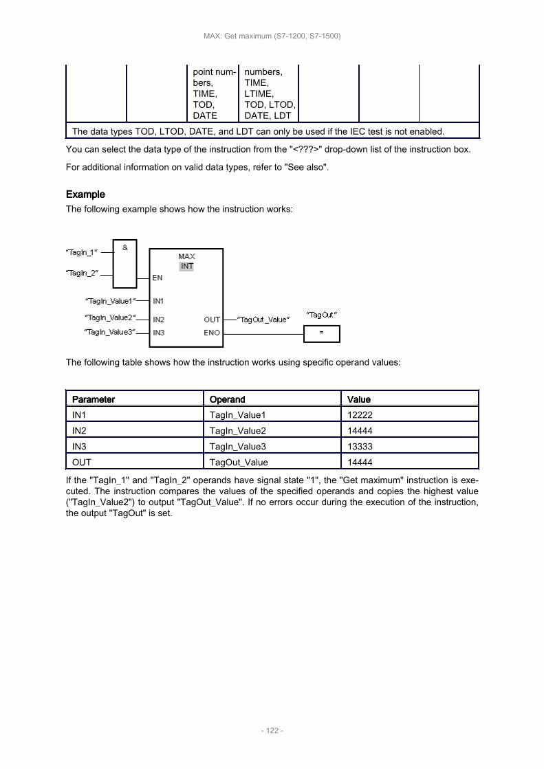
point num‐bers,TIME,TOD,DATE
numbers,TIME,LTIME,TOD, LTOD,DATE, LDT
The data types TOD, LTOD, DATE, and LDT can only be used if the IEC test is not enabled.
You can select the data type of the instruction from the "<???>" drop-down list of the instruction box.
For additional information on valid data types, refer to "See also".
ExampleExampleExampleExampleThe following example shows how the instruction works:
The following table shows how the instruction works using specific operand values:
ParameterParameterParameterParameter OperandOperandOperandOperand ValueValueValueValueIN1 TagIn_Value1 12222IN2 TagIn_Value2 14444IN3 TagIn_Value3 13333OUT TagOut_Value 14444
If the "TagIn_1" and "TagIn_2" operands have signal state "1", the "Get maximum" instruction is exe‐cuted. The instruction compares the values of the specified operands and copies the highest value("TagIn_Value2") to output "TagOut_Value". If no errors occur during the execution of the instruction,the output "TagOut" is set.
MAX: Get maximum (S7-1200, S7-1500)
- 122 -

LIMIT: LIMIT: LIMIT: LIMIT: Set Set Set Set limit limit limit limit valuevaluevaluevalue
Description
You can use the "Set limit value" instruction to limit the value at input IN to the values at the inputs MNand MX. If the value at the IN input meets the MN condition <= IN <= MX, it is copied to the OUToutput. If the condition is not fulfilled and the input value IN is below the low limit MN, output OUT isset to the value of the input MN. If the high limit MX is exceeded, output OUT is set to the value of theinput MX.
If the value at input MN is greater than that at input MX, the result is undefined and the enable outputENO is "0".
Enable output ENO has the signal state "0" if one of the following conditions applies:
• Enable input EN has the signal state "0".
• The specified tags are not of the same data type.
• An operand has an invalid value.
• The value at the MN input is greater than the value at input MX.
ParametersParametersParametersParametersThe following table shows the parameters of the "Set limit value" instruction:
ParameterParameterParameterParameter DeclarationDeclarationDeclarationDeclaration Data Data Data Data typetypetypetype Memory Memory Memory Memory areaareaareaarea DescriptionDescriptionDescriptionDescriptionS7-1200S7-1200S7-1200S7-1200 S7-1500S7-1500S7-1500S7-1500 S7-1200S7-1200S7-1200S7-1200 S7-1500S7-1500S7-1500S7-1500
EN Input BOOL BOOL I, Q, M, D, L I, Q, M, D, L,T, C Enable input
ENO Output BOOL BOOL I, Q, M, D, L I, Q, M, D, L Enable out‐put
MN Input
Integers,floating-point num‐bers,TIME,TOD,DATE
Integers,floating-pointnumbers,TIME,LTIME,TOD, LTOD,DATE, LDT
I, Q, M, D, L,P or con‐stant
I, Q, M, D, L,P or con‐stant
Low limit
IN Input
Integers,floating-point num‐bers,TIME,TOD,DATE
Integers,floating-pointnumbers,TIME,LTIME,TOD, LTOD,DATE, LDT
I, Q, M, D, L,P or con‐stant
I, Q, M, D, L,P or con‐stant
Input value
MX Input
Integers,floating-point num‐bers,TIME,
Integers,floating-pointnumbers,TIME,LTIME,
I, Q, M, D, L,P or con‐stant
I, Q, M, D, L,P or con‐stant
High limit
LIMIT: Set limit value (S7-1200, S7-1500)
- 123 -
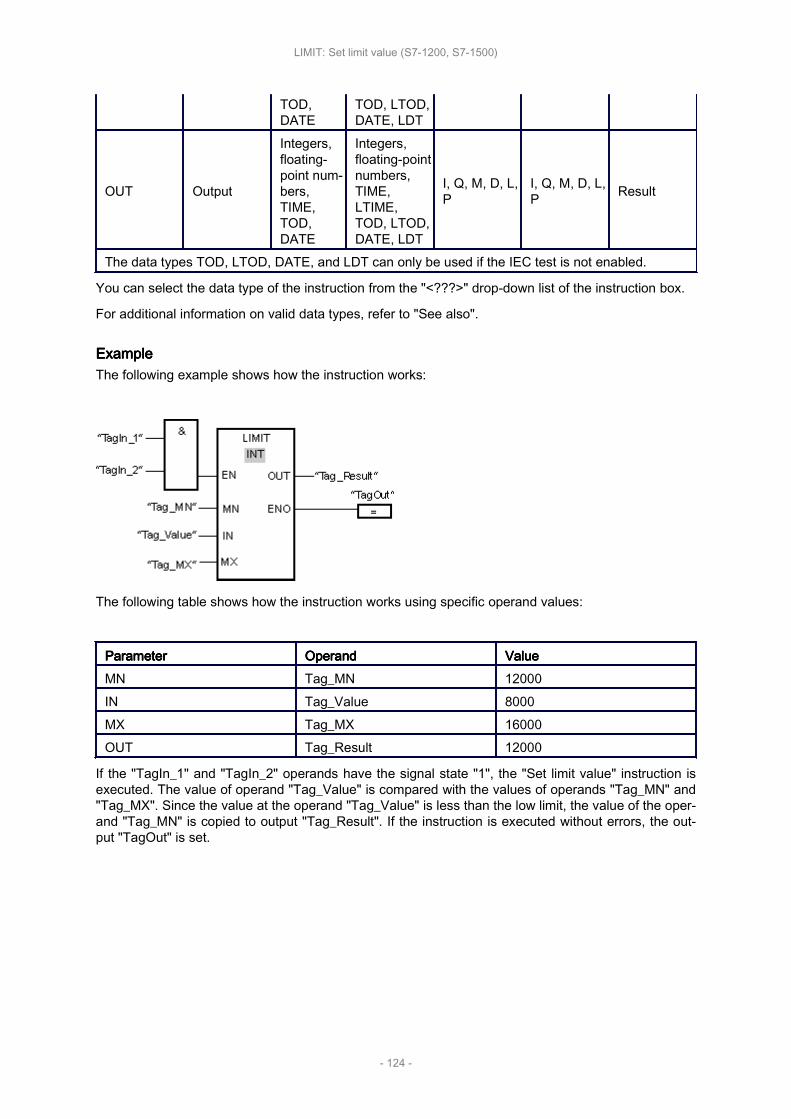
TOD,DATE
TOD, LTOD,DATE, LDT
OUT Output
Integers,floating-point num‐bers,TIME,TOD,DATE
Integers,floating-pointnumbers,TIME,LTIME,TOD, LTOD,DATE, LDT
I, Q, M, D, L,P
I, Q, M, D, L,P Result
The data types TOD, LTOD, DATE, and LDT can only be used if the IEC test is not enabled.
You can select the data type of the instruction from the "<???>" drop-down list of the instruction box.
For additional information on valid data types, refer to "See also".
ExampleExampleExampleExampleThe following example shows how the instruction works:
The following table shows how the instruction works using specific operand values:
ParameterParameterParameterParameter OperandOperandOperandOperand ValueValueValueValueMN Tag_MN 12000IN Tag_Value 8000MX Tag_MX 16000OUT Tag_Result 12000
If the "TagIn_1" and "TagIn_2" operands have the signal state "1", the "Set limit value" instruction isexecuted. The value of operand "Tag_Value" is compared with the values of operands "Tag_MN" and"Tag_MX". Since the value at the operand "Tag_Value" is less than the low limit, the value of the oper‐and "Tag_MN" is copied to output "Tag_Result". If the instruction is executed without errors, the out‐put "TagOut" is set.
LIMIT: Set limit value (S7-1200, S7-1500)
- 124 -

SQR: SQR: SQR: SQR: Form Form Form Form squaresquaresquaresquare
Description
You can use the "Form square" instruction to square the value at input IN and query the result at out‐put OUT.
Enable output ENO has the signal state "0" if one of the following conditions applies:
• Enable input EN has the signal state "0".
• The value at input IN is not a valid floating-point number.
ParametersParametersParametersParametersThe following table shows the parameters of the instruction "Form square":
ParametersParametersParametersParameters DeclarationDeclarationDeclarationDeclaration Data Data Data Data typetypetypetype Memory Memory Memory Memory areaareaareaarea DescriptionDescriptionDescriptionDescriptionS7-1200S7-1200S7-1200S7-1200 S7-1500S7-1500S7-1500S7-1500
EN Input BOOL I, Q, M, D, L I, Q, M, D, L,T, C Enable input
ENO Output BOOL I, Q, M, D, L I, Q, M, D, L Enable output
IN Input Floating-pointnumbers
I, Q, M, D, L, Por constant
I, Q, M, D, L, Por constant Input value
OUT Output Floating-pointnumbers I, Q, M, D, L, P I, Q, M, D, L, P Square of the
input value
You can select the data type of the instruction from the "<???>" drop-down list of the instruction box.
For additional information on valid data types, refer to "See also".
ExampleExampleExampleExampleThe following example shows how the instruction works:
The following table shows how the instruction works using specific operand values:
ParametersParametersParametersParameters OperandOperandOperandOperand ValueValueValueValueIN Tag_Value 5.0OUT Tag_Result 25.0
SQR: Form square (S7-1200, S7-1500)
- 125 -

If the operand "TagIn" has the signal state "1", the "Form square" instruction is executed. The instruc‐tion squares the value of the operand "Tag_Value" and sends the result to output "Tag_Result". If noerrors occur during the execution of the instruction, the output "TagOut" is set.
SQR: Form square (S7-1200, S7-1500)
- 126 -

SQRT: SQRT: SQRT: SQRT: Form Form Form Form square square square square rootrootrootroot
Description
You can use the "Form square root" instruction to form the square root of the value at input IN andquery the result at output OUT. The instruction has a positive result if the input value is greater thanzero. If input values are less than zero, output OUT returns an invalid floating-point number. If the val‐ue at input IN is "0", the result is also "0".
Enable output ENO has the signal state "0" if one of the following conditions applies:
• Enable input EN has the signal state "0".
• The value at input IN is not a valid floating-point number.
• The value at input IN is negative.
ParametersParametersParametersParametersThe following table shows the parameters of the instruction "Form square root":
ParametersParametersParametersParameters DeclarationDeclarationDeclarationDeclaration Data Data Data Data typetypetypetype Memory Memory Memory Memory areaareaareaarea DescriptionDescriptionDescriptionDescriptionS7-1200S7-1200S7-1200S7-1200 S7-1500S7-1500S7-1500S7-1500
EN Input BOOL I, Q, M, D, L I, Q, M, D, L,T, C Enable input
ENO Output BOOL I, Q, M, D, L I, Q, M, D, L Enable output
IN Input Floating-pointnumbers
I, Q, M, D, L, Por constant
I, Q, M, D, L, Por constant Input value
OUT Output Floating-pointnumbers I, Q, M, D, L I, Q, M, D, L Square root of
the input value
You can select the data type of the instruction from the "<???>" drop-down list of the instruction box.
For additional information on valid data types, refer to "See also".
ExampleExampleExampleExampleThe following example shows how the instruction works:
The following table shows how the instruction works using specific operand values:
SQRT: Form square root (S7-1200, S7-1500)
- 127 -
ParametersParametersParametersParameters OperandOperandOperandOperand ValueValueValueValueIN Tag_Value 25.0OUT Tag_Result 5.0
If the operand "TagIn" has the signal state "1", the "Form square root" instruction is executed. Theinstruction calculates the square root of the operand "Tag_Value" and sends the result to output"Tag_Result". If no errors occur during the execution of the instruction, the output "TagOut" is set.
SQRT: Form square root (S7-1200, S7-1500)
- 128 -

Move Move Move Move operationsoperationsoperationsoperations
This chapter contains the following information:
• MOVE: MOVE: MOVE: MOVE: Move Move Move Move value value value value (S7-1200, (S7-1200, (S7-1200, (S7-1200, S7-1500)S7-1500)S7-1500)S7-1500)
• Deserialize: Deserialize: Deserialize: Deserialize: Deserialize Deserialize Deserialize Deserialize (S7-1500)(S7-1500)(S7-1500)(S7-1500)
• Serialize: Serialize: Serialize: Serialize: Serialize Serialize Serialize Serialize (S7-1500)(S7-1500)(S7-1500)(S7-1500)
• FieldRead: FieldRead: FieldRead: FieldRead: Read Read Read Read field field field field (S7-1200, (S7-1200, (S7-1200, (S7-1200, S7-1500)S7-1500)S7-1500)S7-1500)
• FieldWrite: FieldWrite: FieldWrite: FieldWrite: Write Write Write Write field field field field (S7-1200, (S7-1200, (S7-1200, (S7-1200, S7-1500)S7-1500)S7-1500)S7-1500)
• MOVE_BLK: MOVE_BLK: MOVE_BLK: MOVE_BLK: Move Move Move Move block block block block (S7-1200, (S7-1200, (S7-1200, (S7-1200, S7-1500)S7-1500)S7-1500)S7-1500)
• MOVE_BLK_VARIANT: MOVE_BLK_VARIANT: MOVE_BLK_VARIANT: MOVE_BLK_VARIANT: Move Move Move Move block block block block (S7-1500)(S7-1500)(S7-1500)(S7-1500)
• UMOVE_BLK: UMOVE_BLK: UMOVE_BLK: UMOVE_BLK: Move Move Move Move block block block block uninterruptible uninterruptible uninterruptible uninterruptible (S7-1200, (S7-1200, (S7-1200, (S7-1200, S7-1500)S7-1500)S7-1500)S7-1500)
• FILL_BLK: FILL_BLK: FILL_BLK: FILL_BLK: Fill Fill Fill Fill block block block block (S7-1200, (S7-1200, (S7-1200, (S7-1200, S7-1500)S7-1500)S7-1500)S7-1500)
• UFILL_BLK: UFILL_BLK: UFILL_BLK: UFILL_BLK: Fill Fill Fill Fill block block block block uninterruptible uninterruptible uninterruptible uninterruptible (S7-1200, (S7-1200, (S7-1200, (S7-1200, S7-1500)S7-1500)S7-1500)S7-1500)
• SWAP: SWAP: SWAP: SWAP: Swap Swap Swap Swap (S7-1200, (S7-1200, (S7-1200, (S7-1200, S7-1500)S7-1500)S7-1500)S7-1500)
• ARRAY ARRAY ARRAY ARRAY DB DB DB DB instructions instructions instructions instructions (S7-1500)(S7-1500)(S7-1500)(S7-1500)
• VARIANT VARIANT VARIANT VARIANT instructions instructions instructions instructions (S7-1500)(S7-1500)(S7-1500)(S7-1500)
• Other Other Other Other (S7-1500)(S7-1500)(S7-1500)(S7-1500)
Move operations (S7-1200, S7-1500)
- 129 -

MOVE: MOVE: MOVE: MOVE: Move Move Move Move valuevaluevaluevalue
Description
You use the "Move value" instruction to transfer the content of the operand at the IN input to the oper‐and at the OUT1 output. The transfer is always made in the direction of ascending address.
The ENO enable output has the signal state "0" if one of the following conditions is fulfilled:
• The EN enable input has the signal state "0".
• The data type at the IN parameter does not correspond to the specified data type at the OUT1 pa‐rameter.
The following table lists the possible transfers for the S7-1200 CPU series:
Source Source Source Source (IN)(IN)(IN)(IN) Destination Destination Destination Destination (OUT1)(OUT1)(OUT1)(OUT1)With With With With IEC IEC IEC IEC checkcheckcheckcheck Without Without Without Without IEC IEC IEC IEC checkcheckcheckcheck
BYTE BYTE, WORD, DWORD BYTE, WORD, DWORD, SINT, USINT, INT, UINT,DINT, UDINT, TIME, DATE ,TOD, CHAR
WORD WORD, DWORD BYTE, WORD, DWORD, SINT, USINT, INT, UINT,DINT, UDINT, TIME, DATE, TOD, CHAR
DWORD DWORD BYTE, WORD, DWORD, SINT, USINT, INT, UINT,DINT, UDINT, REAL, TIME, DATE, TOD, CHAR
SINT SINT BYTE, WORD, DWORD, SINT, USINT, INT, UINT,DINT, UDINT, TIME, DATE, TOD
USINT USINT, UINT, UDINT BYTE, WORD, DWORD, SINT, USINT, INT, UINT,DINT, UDINT, TIME, DATE, TOD
INT INT BYTE, WORD, DWORD, SINT, USINT, INT, UINT,DINT, UDINT, TIME, DATE, TOD
UINT UINT, UDINT BYTE, WORD, DWORD, SINT, USINT, INT, UINT,DINT, UDINT, TIME, DATE, TOD
DINT DINT BYTE, WORD, DWORD, SINT, USINT, INT, UINT,DINT, UDINT, TIME, DATE, TOD
UDINT UDINT BYTE, WORD, DWORD, SINT, USINT, INT, UINT,DINT, UDINT, TIME, DATE, TOD
REAL REAL DWORD, REALLREAL LREAL LREAL
TIME TIME BYTE, WORD, DWORD, SINT, USINT, INT, UINT,DINT, UDINT, TIME
DATE DATE BYTE, WORD, DWORD, SINT, USINT, INT, UINT,DINT, UDINT, DATE
TOD TOD BYTE, WORD, DWORD, SINT, USINT, INT, UINT,DINT, UDINT, TOD
DTL DTL DTL
CHAR CHAR BYTE, WORD, DWORD, CHAR, Character of astring1)
MOVE: Move value (S7-1200, S7-1500)
- 130 -

Character of astring1) Character of a string Character of a string CHAR
ARRAY2) ARRAY ARRAY
STRUCT STRUCT STRUCTPLC data type(UDT) PLC data type (UDT) PLC data type (UDT)
IEC_TIMER IEC_TIMER IEC_TIMERIEC_SCOUNT‐ER IEC_SCOUNTER IEC_SCOUNTER
IEC_US‐COUNTER IEC_USCOUNTER IEC_USCOUNTER
IEC_COUN‐TER IEC_COUNTER IEC_COUNTER
IEC_UCOUNT‐ER IEC_UCOUNTER IEC_UCOUNTER
IEC_DCOUNT‐ER IEC_DCOUNTER IEC_DCOUNTER
IEC_UD‐COUNTER IEC_UDCOUNTER IEC_UDCOUNTER
The following table lists the possible transfers for the S7-1500 CPU series:
Source Source Source Source (IN)(IN)(IN)(IN) Destination Destination Destination Destination (OUT1)(OUT1)(OUT1)(OUT1)With With With With IEC IEC IEC IEC checkcheckcheckcheck Without Without Without Without IEC IEC IEC IEC checkcheckcheckcheck
BYTE BYTE, WORD, DWORD,LWORD
BYTE, WORD, DWORD, LWORD, SINT, USINT,INT, UINT, DINT, UDINT, LINT, ULINT, TIME,LTIME, LDT, DATE ,TOD, LTOD, CHAR
WORD WORD, DWORD, LWORDBYTE, WORD, DWORD, LWORD, SINT, USINT,INT, UINT, DINT, UDINT, LINT, ULINT, S5TIME,TIME, LTIME, LDT, DATE, TOD, LTOD, CHAR
DWORD DWORD, LWORDBYTE, WORD, DWORD, LWORD, SINT, USINT,INT, UINT, DINT, UDINT, LINT, ULINT, REAL,TIME, LTIME, LDT, DATE, TOD, LTOD, CHAR
LWORD LWORDBYTE, WORD, DWORD, LWORD, SINT, USINT,INT, UINT, DINT, UDINT, LINT, ULINT, LREAL,TIME, LTIME, LDT, DATE, TOD, LTOD, CHAR
SINT SINTBYTE, WORD, DWORD, LWORD, SINT, USINT,INT, UINT, DINT, UDINT, LINT, ULINT, TIME,LTIME, LDT, DATE, TOD, LTOD
USINT USINT, UINT, UDINT,ULINT
BYTE, WORD, DWORD, LWORD, SINT, USINT,INT, UINT, DINT, UDINT, LINT, ULINT, TIME,LTIME, LDT, DATE, TOD, LTOD
INT INTBYTE, WORD, DWORD, LWORD, SINT, USINT,INT, UINT, DINT, UDINT, LINT, ULINT, TIME,LTIME, LDT, DATE, TOD, LTOD
UINT UINT, UDINT, ULINTBYTE, WORD, DWORD, LWORD, SINT, USINT,INT, UINT, DINT, UDINT, LINT, ULINT, TIME,LTIME, LDT, DATE, TOD. LTOD
MOVE: Move value (S7-1200, S7-1500)
- 131 -

DINT DINTBYTE, WORD, DWORD, LWORD, SINT, USINT,INT, UINT, DINT, UDINT, LINT, ULINT, TIME,LTIME, LDT, DATE, TOD, LTOD
UDINT UDINT, ULINTBYTE, WORD, DWORD, LWORD, SINT, USINT,INT, UINT, DINT, UDINT, LINT, ULINT, TIME,LTIME, LDT, DATE, TOD, LTOD
LINT LINTBYTE, WORD, DWORD, LWORD, SINT, USINT,INT, UINT, DINT, UDINT, LINT, ULINT, TIME,LTIME, LDT, DATE, TOD, LTOD
ULINT ULINTBYTE, WORD, DWORD, LWORD, SINT, USINT,INT, UINT, DINT, UDINT, LINT, ULINT, TIME,LTIME, LDT, DATE, TOD, LTOD
REAL REAL DWORD, REALLREAL LREAL LWORD, LREALS5TIME S5TIME WORD, S5TIME
TIME TIME BYTE, WORD, DWORD, LWORD, SINT, USINT,INT, UINT, DINT, UDINT, LINT, ULINT, TIME
LTIME LTIME BYTE, WORD, DWORD, LWORD, SINT, USINT,INT, UINT, DINT, UDINT, LINT, ULINT, LTIME
DATE DATE BYTE, WORD, DWORD, LWORD, SINT, USINT,INT, UINT, DINT, UDINT, LINT, ULINT, DATE
DT DT DT
LDT LDT BYTE, WORD, DWORD, LWORD, SINT, USINT,INT, UINT, DINT, UDINT, LINT, ULINT, LDT
TOD TOD BYTE, WORD, DWORD, LWORD, SINT, USINT,INT, UINT, DINT, UDINT, LINT, ULINT, TOD
LTOD LTOD BYTE, WORD, DWORD, LWORD, SINT, USINT,INT, UINT, DINT, UDINT, LINT, ULINT, LTOD
DTL DTL DTL
CHAR CHAR BYTE, WORD, DWORD, LWORD, CHAR, Charac‐ter of a string1)
WCHAR WCHARBYTE, WORD, DWORD, LWORD, CHAR, WCHAR,Character of a string1)
Character of astring1) Character of a string CHAR, WCHAR, Character of a string
ARRAY2) ARRAY ARRAY
STRUCT STRUCT STRUCTCOUNTER COUNTER, WORD, INT WORD, DWORD, INT, UINT, DINT, UDINTTIMER TIMER, WORD, INT WORD, DWORD, INT, UINT, DINT, UDINTPLC data type(UDT) PLC data type (UDT) PLC data type (UDT)
IEC_TIMER IEC_TIMER IEC_TIMERIEC_LTIMER IEC_LTIMER IEC_LTIMERIEC_SCOUNT‐ER IEC_SCOUNTER IEC_SCOUNTER
MOVE: Move value (S7-1200, S7-1500)
- 132 -
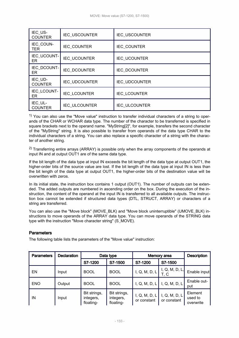
IEC_US‐COUNTER IEC_USCOUNTER IEC_USCOUNTER
IEC_COUN‐TER IEC_COUNTER IEC_COUNTER
IEC_UCOUNT‐ER IEC_UCOUNTER IEC_UCOUNTER
IEC_DCOUNT‐ER IEC_DCOUNTER IEC_DCOUNTER
IEC_UD‐COUNTER IEC_UDCOUNTER IEC_UDCOUNTER
IEC_LCOUNT‐ER IEC_LCOUNTER IEC_LCOUNTER
IEC_UL‐COUNTER IEC_ULCOUNTER IEC_ULCOUNTER
1) You can also use the "Move value" instruction to transfer individual characters of a string to oper‐ands of the CHAR or WCHAR data type. The number of the character to be transferred is specified insquare brackets next to the operand name. "MyString[2]", for example, transfers the second characterof the "MyString" string. It is also possible to transfer from operands of the data type CHAR to theindividual characters of a string. You can also replace a specific character of a string with the charac‐ter of another string.
2) Transferring entire arrays (ARRAY) is possible only when the array components of the operands atinput IN and at output OUT1 are of the same data type.
If the bit length of the data type at input IN exceeds the bit length of the data type at output OUT1, thehigher-order bits of the source value are lost. If the bit length of the data type at input IN is less thanthe bit length of the data type at output OUT1, the higher-order bits of the destination value will beoverwritten with zeros.
In its initial state, the instruction box contains 1 output (OUT1). The number of outputs can be exten‐ded. The added outputs are numbered in ascending order on the box. During the execution of the in‐struction, the content of the operand at the input IN is transferred to all available outputs. The instruc‐tion box cannot be extended if structured data types (DTL, STRUCT, ARRAY) or characters of astring are transferred.
You can also use the "Move block" (MOVE_BLK) and "Move block uninterruptible" (UMOVE_BLK) in‐structions to move operands of the ARRAY data type. You can move operands of the STRING datatype with the instruction "Move character string" (S_MOVE).
ParametersParametersParametersParametersThe following table lists the parameters of the "Move value" instruction:
ParametersParametersParametersParameters DeclarationDeclarationDeclarationDeclaration Data Data Data Data typetypetypetype Memory Memory Memory Memory areaareaareaarea DescriptionDescriptionDescriptionDescriptionS7-1200S7-1200S7-1200S7-1200 S7-1500S7-1500S7-1500S7-1500 S7-1200S7-1200S7-1200S7-1200 S7-1500S7-1500S7-1500S7-1500
EN Input BOOL BOOL I, Q, M, D, L I, Q, M, D, L,T, C Enable input
ENO Output BOOL BOOL I, Q, M, D, L I, Q, M, D, L Enable out‐put
IN InputBit strings,integers,floating-
Bit strings,integers,floating-
I, Q, M, D, Lor constant
I, Q, M, D, Lor constant
Elementused tooverwrite
MOVE: Move value (S7-1200, S7-1500)
- 133 -

point num‐bers, DATE,TIME, TOD,DTL, CHAR,STRUCT,ARRAY, IECdata types,PLC datatype (UDT)
point num‐bers, DATE,DT, LDT,S5TIME,TIME,LTIME,TOD, LTOD,DTL, CHAR,STRUCT,ARRAY,TIMER,COUNTER,IEC datatypes, PLCdata type(UDT)
the destina‐tion ad‐dress.
OUT1 Output
Bit strings,integers,floating-point num‐bers, DATE,TIME, TOD,DTL, CHAR,STRUCT,ARRAY, IECdata types,PLC datatype (UDT)
Bit strings,integers,floating-point num‐bers, DATE,DT, LDT,S5TIME,TIME,LTIME,TOD, LTOD,DTL, CHAR,STRUCT,ARRAY,TIMER,COUNTER,IEC datatypes, PLCdata type(UDT)
I, Q, M, D, L I, Q, M, D, L Destinationaddress
For additional information on valid data types, refer to "See also".
ExampleExampleExampleExampleThe following example shows how the instruction works:
The following table lists how the instruction works using specific operand values:
ParametersParametersParametersParameters OperandOperandOperandOperand ValueValueValueValueIN TagIn_Value 0011 1111 1010 1111OUT1 TagOut_Value 0011 1111 1010 1111
MOVE: Move value (S7-1200, S7-1500)
- 134 -

If the operand "TagIn" has the signal state "1", the "Move value" instruction is executed. The instruc‐tion copies the content of the "TagIn_Value" operand to the "TagOut_Value" operand. If the instructionis executed without errors, the ENO and "TagOut" enable outputs are set to signal state "1".
MOVE: Move value (S7-1200, S7-1500)
- 135 -
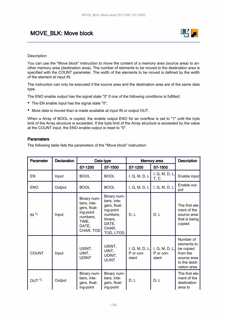
MOVE_BLK: MOVE_BLK: MOVE_BLK: MOVE_BLK: Move Move Move Move blockblockblockblock
Description
You can use the "Move block" instruction to move the content of a memory area (source area) to an‐other memory area (destination area). The number of elements to be moved to the destination area isspecified with the COUNT parameter. The width of the elements to be moved is defined by the widthof the element at input IN.
The instruction can only be executed if the source area and the destination area are of the same datatype.
The ENO enable output has the signal state "0" if one of the following conditions is fulfilled:
• The EN enable input has the signal state "0".
• More data is moved than is made available at input IN or output OUT.
When a Array of BOOL is copied, the enable output ENO for an overflow is set to "1" until the bytelimit of the Array structure is exceeded. If the byte limit of the Array structure is exceeded by the valueat the COUNT input, the ENO enable output is reset to "0".
ParametersParametersParametersParametersThe following table lists the parameters of the "Move block" instruction:
ParameterParameterParameterParameter DeclarationDeclarationDeclarationDeclaration Data Data Data Data typetypetypetype Memory Memory Memory Memory areaareaareaarea DescriptionDescriptionDescriptionDescriptionS7-1200S7-1200S7-1200S7-1200 S7-1500S7-1500S7-1500S7-1500 S7-1200S7-1200S7-1200S7-1200 S7-1500S7-1500S7-1500S7-1500
EN Input BOOL BOOL I, Q, M, D, L I, Q, M, D, L,T, C Enable input
ENO Output BOOL BOOL I, Q, M, D, L I, Q, M, D, L Enable out‐put
IN 1) Input
Binary num‐bers, inte‐gers, float‐ing-pointnumbers,TIME,DATE,CHAR, TOD
Binary num‐bers, inte‐gers, float‐ing-pointnumbers,timers,DATE,CHAR,TOD, LTOD
D, L D, L
The first ele‐ment of thesource areathat is beingcopied
COUNT InputUSINT,UINT,UDINT
USINT,UINT,UDINT,ULINT
I, Q, M, D, L,P or con‐stant
I, Q, M, D, L,P or con‐stant
Number ofelements tobe copiedfrom thesource areato the desti‐nation area
OUT 1) Output
Binary num‐bers, inte‐gers, float‐ing-point
Binary num‐bers, inte‐gers, float‐ing-point
D, L D, L
The first ele‐ment of thedestinationarea to
MOVE_BLK: Move block (S7-1200, S7-1500)
- 136 -

numbers,TIME,DATE,CHAR, TOD
numbers,timers,DATE,CHAR,TOD, LTOD
which thecontents ofthe sourcearea are be‐ing copied
1) The specified data types can only be used as elements of an Array structure.
For additional information on valid data types, refer to "See also".
ExampleExampleExampleExampleThe following example shows how the instruction works:
The following table shows how the instruction works using specific operand values:
ParameterParameterParameterParameter OperandOperandOperandOperand ValueValueValueValue
IN a_array[2]
The data type of the a_array op‐erand is Array [0..5] of INT. Itconsists of six elements of datatype INT.
COUNT Tag_Count 3
OUT b_array[1]
The data type of the b_array op‐erand is Array [0..6] of INT. Itconsists of seven elements ofdata type INT.
If the operands "TagIn_1" and "TagIn_2" have signal state "1", the "Move block" instruction is execu‐ted. Starting from the third element, the instruction selects three INT elements from the #a_array tagand copies their contents to the #b_array output tag, beginning with the second element. If the instruc‐tion is executed without errors, the ENO enable output has the signal state "1" and the "TagOut" out‐put is set.
MOVE_BLK: Move block (S7-1200, S7-1500)
- 137 -
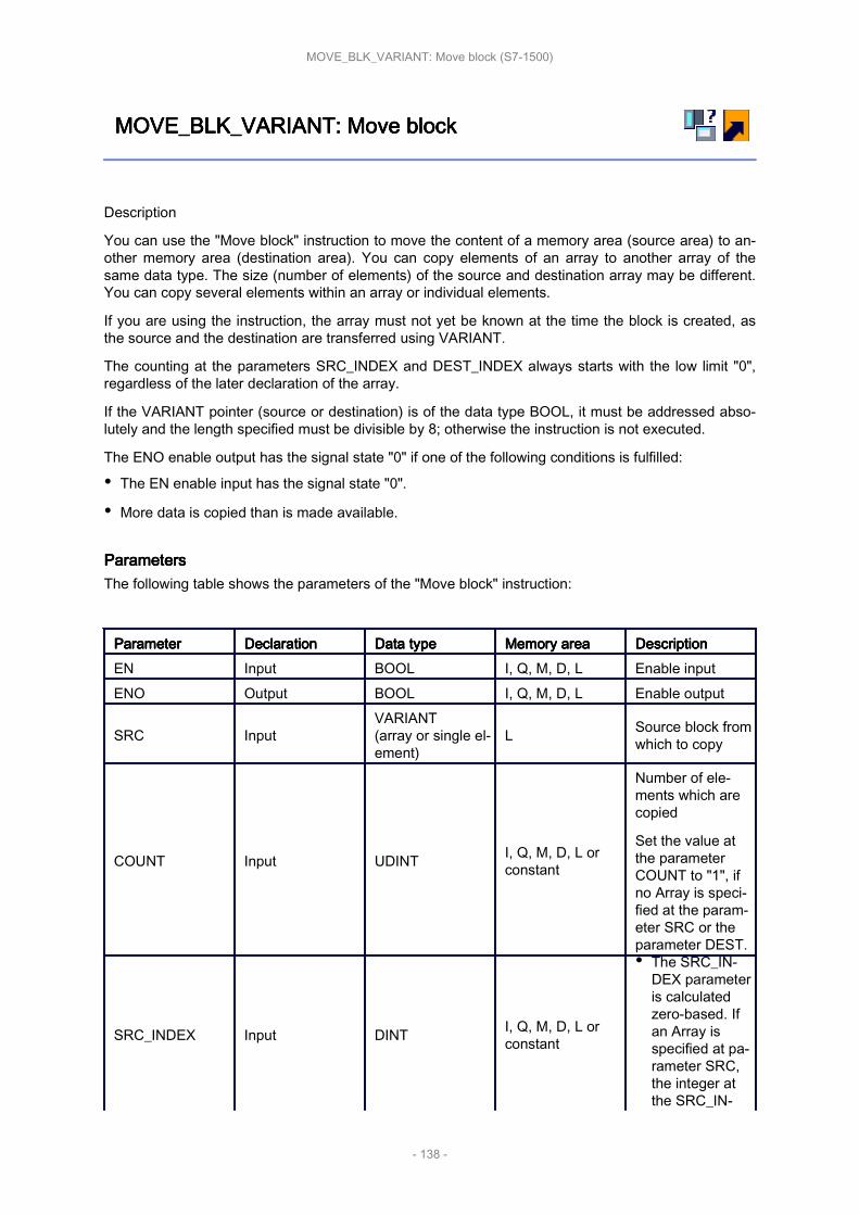
MOVE_BLK_VARIANT: MOVE_BLK_VARIANT: MOVE_BLK_VARIANT: MOVE_BLK_VARIANT: Move Move Move Move blockblockblockblock
Description
You can use the "Move block" instruction to move the content of a memory area (source area) to an‐other memory area (destination area). You can copy elements of an array to another array of thesame data type. The size (number of elements) of the source and destination array may be different.You can copy several elements within an array or individual elements.
If you are using the instruction, the array must not yet be known at the time the block is created, asthe source and the destination are transferred using VARIANT.
The counting at the parameters SRC_INDEX and DEST_INDEX always starts with the low limit "0",regardless of the later declaration of the array.
If the VARIANT pointer (source or destination) is of the data type BOOL, it must be addressed abso‐lutely and the length specified must be divisible by 8; otherwise the instruction is not executed.
The ENO enable output has the signal state "0" if one of the following conditions is fulfilled:
• The EN enable input has the signal state "0".
• More data is copied than is made available.
ParametersParametersParametersParametersThe following table shows the parameters of the "Move block" instruction:
ParameterParameterParameterParameter DeclarationDeclarationDeclarationDeclaration Data Data Data Data typetypetypetype Memory Memory Memory Memory areaareaareaarea DescriptionDescriptionDescriptionDescriptionEN Input BOOL I, Q, M, D, L Enable inputENO Output BOOL I, Q, M, D, L Enable output
SRC InputVARIANT(array or single el‐ement)
L Source block fromwhich to copy
COUNT Input UDINT I, Q, M, D, L orconstant
Number of ele‐ments which arecopied
Set the value atthe parameterCOUNT to "1", ifno Array is speci‐fied at the param‐eter SRC or theparameter DEST.
SRC_INDEX Input DINT I, Q, M, D, L orconstant
• The SRC_IN‐DEX parameteris calculatedzero-based. Ifan Array isspecified at pa‐rameter SRC,the integer atthe SRC_IN‐
MOVE_BLK_VARIANT: Move block (S7-1500)
- 138 -

DEX parameterspecifies thefirst elementwithin thesource areafrom whichcopying is totake place. Thisis independentof the declaredarray limits.• If no Array is
set at the SRCparameter oronly an individ‐ual element ofan array isspecified, as‐sign theSRC_INDEXparameter thevalue "0".
DEST_INDEX Input DINT I, Q, M, D, L orconstant
• The DEST_IN‐DEX parameteris calculatedzero-based. Ifan Array isspecified at theDEST parame‐ter, the integerat theDEST_INDEXparameterspecifies thefirst elementwithin the desti‐nation area towhich copyingis to take place.This is inde‐pendent of thedeclared arraylimits.• If no Array is
specified at theDEST parame‐ter, assign theDEST_INDEXparameter thevalue "0".
DEST Output VARIANT L
Destination areainto which thecontents of thesource block arecopied.
RET_VAL Output INT I, Q, M, D, L Error information:
MOVE_BLK_VARIANT: Move block (S7-1500)
- 139 -
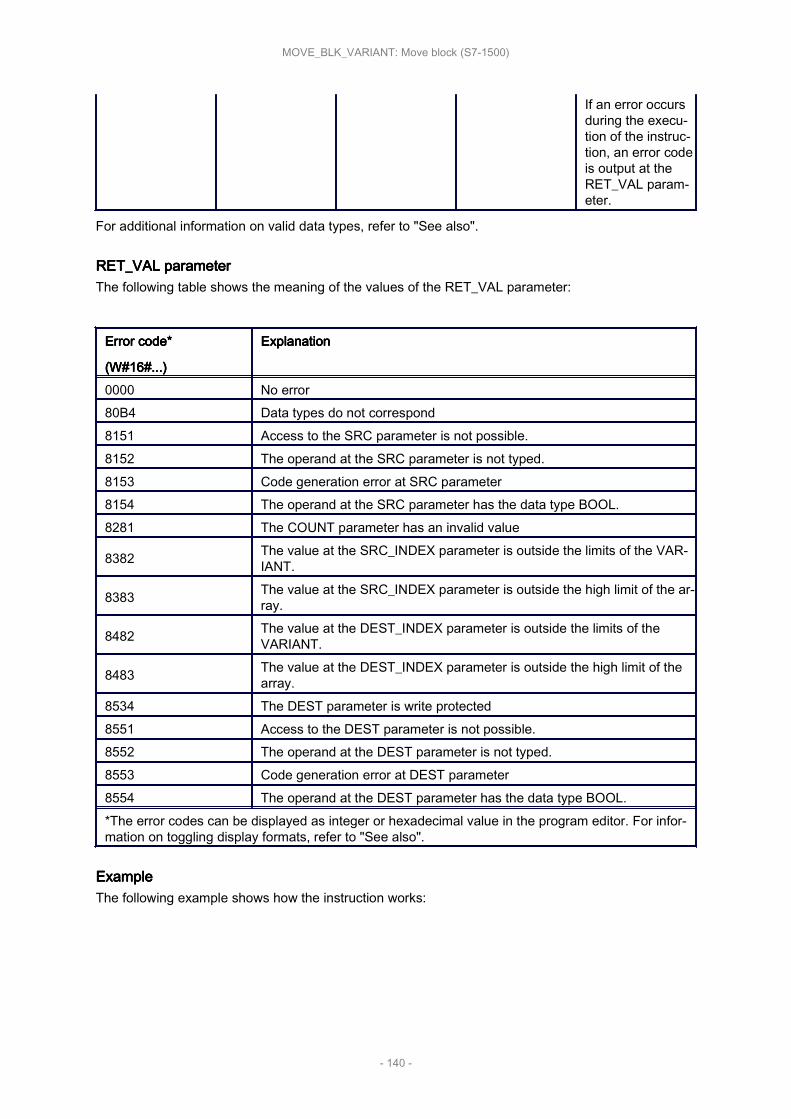
If an error occursduring the execu‐tion of the instruc‐tion, an error codeis output at theRET_VAL param‐eter.
For additional information on valid data types, refer to "See also".
RET_VAL RET_VAL RET_VAL RET_VAL parameterparameterparameterparameterThe following table shows the meaning of the values of the RET_VAL parameter:
Error Error Error Error code*code*code*code*
(W#16#...)(W#16#...)(W#16#...)(W#16#...)
ExplanationExplanationExplanationExplanation
0000 No error80B4 Data types do not correspond8151 Access to the SRC parameter is not possible.8152 The operand at the SRC parameter is not typed.8153 Code generation error at SRC parameter8154 The operand at the SRC parameter has the data type BOOL.8281 The COUNT parameter has an invalid value
8382 The value at the SRC_INDEX parameter is outside the limits of the VAR‐IANT.
8383 The value at the SRC_INDEX parameter is outside the high limit of the ar‐ray.
8482 The value at the DEST_INDEX parameter is outside the limits of theVARIANT.
8483 The value at the DEST_INDEX parameter is outside the high limit of thearray.
8534 The DEST parameter is write protected8551 Access to the DEST parameter is not possible.8552 The operand at the DEST parameter is not typed.8553 Code generation error at DEST parameter8554 The operand at the DEST parameter has the data type BOOL.*The error codes can be displayed as integer or hexadecimal value in the program editor. For infor‐mation on toggling display formats, refer to "See also".
ExampleExampleExampleExampleThe following example shows how the instruction works:
MOVE_BLK_VARIANT: Move block (S7-1500)
- 140 -

The following table shows how the instruction works using specific operand values:
ParameterParameterParameterParameter OperandOperandOperandOperand ValueValueValueValue
SRC #SrcField
The local operand #SrcFielduses a UDT that was still un‐known at the time when theblock was programmed. (Array[0 to 10] of "MOVE_UDT"
COUNT Tag_Count 2SRC_INDEX Tag_Src_Index 3DEST_INDEX Tag_Dest_Index 3
DEST #DestField
The local operand #DestFielduses a UDT that was still un‐known at the time when theblock was programmed. (Array[10 to 20] of "MOVE_UDT"
If the operand "TagIn" has the signal state "1", the "Move block" instruction is executed. 2 elementsare copied from the source area into the destination area beginning with the fourth element of the ar‐ray of UDT. The copies are inserted in the array of UDT beginning with the fourth element. If the in‐struction is executed without errors, the ENO enable output has the signal state "1" and the "TagOut"output is set.
MOVE_BLK_VARIANT: Move block (S7-1500)
- 141 -

UMOVE_BLK: UMOVE_BLK: UMOVE_BLK: UMOVE_BLK: Move Move Move Move block block block block uninterruptibleuninterruptibleuninterruptibleuninterruptible
Description
You can use the "Move block uninterruptible" instruction to move the content of a memory area(source area) to another memory area (destination area). The number of elements to be moved to thedestination area is specified with the COUNT parameter. The width of the elements to be moved isdefined by the width of the element at input IN.
The instruction can only be executed if the source area and the destination area have the same datatype.
NoteNoteNoteNoteThe move operation cannot be interrupted by other operating system activities. This is why thealarm reaction times of the CPU increase during the execution of the "Move block uninterruptible"instruction.
The ENO enable output has the signal state "0" if one of the following conditions is fulfilled:
• The EN enable input has the signal state "0".
• More data is moved than is made available at input IN or output OUT.
When a Array of BOOL is copied, the enable output ENO for an overflow is set to "1" until the bytelimit of the Array structure is exceeded. If the byte limit of the Array structure is exceeded by the valueat the COUNT input, the ENO enable output is reset to "0".
You can use the "Move block uninterruptible" instruction to move a maximum of 16 KB. Note theCPU-specific restrictions for this.
ParametersParametersParametersParametersThe following table shows the parameters of the "Move block uninterruptible" instruction:
ParameterParameterParameterParameter DeclarationDeclarationDeclarationDeclaration Data Data Data Data typetypetypetype Memory Memory Memory Memory areaareaareaarea DescriptionDescriptionDescriptionDescriptionS7-1200S7-1200S7-1200S7-1200 S7-1500S7-1500S7-1500S7-1500 S7-1200S7-1200S7-1200S7-1200 S7-1500S7-1500S7-1500S7-1500
EN Input BOOL BOOL I, Q, M, D, L I, Q, M, D, L,T, C Enable input
ENO Output BOOL BOOL I, Q, M, D, L I, Q, M, D, L Enable out‐put
IN 1) Input
Binary num‐bers, inte‐gers, float‐ing-pointnumbers,TIME,DATE,CHAR, TOD
Binary num‐bers, inte‐gers, float‐ing-pointnumbers,timers,DATE,CHAR,TOD, LTOD
D, L D, L
The first ele‐ment of thesource areathat is beingcopied
COUNT InputUSINT,UINT,UDINT
USINT,UINT,UDINT,ULINT
I, Q, M, D, L,P or con‐stant
I, Q, M, D, L,P or con‐stant
Number ofelements tobe copiedfrom the
UMOVE_BLK: Move block uninterruptible (S7-1200, S7-1500)
- 142 -

source areato the desti‐nation area
OUT 1) Output
Binary num‐bers, inte‐gers, float‐ing-pointnumbers,TIME,DATE,CHAR, TOD
Binary num‐bers, inte‐gers, float‐ing-pointnumbers,timers,DATE,CHAR,TOD, LTOD
D, L D, L
The first ele‐ment of thedestinationarea towhich thecontents ofthe sourcearea are be‐ing copied
1) The specified data types can only be used as elements of an array structure.
For additional information on valid data types, refer to "See also".
ExampleExampleExampleExampleThe following example shows how the instruction works:
The following table shows how the instruction works using specific operand values:
ParameterParameterParameterParameter OperandOperandOperandOperand ValueValueValueValue
IN a_array[2]
The data type of the a_array op‐erand is Array [0..5] of INT. Itconsists of six elements of datatype INT.
COUNT Tag_Count 3
OUT b_array[1]
The data type of the b_array op‐erand is Array [0..6] of INT. Itconsists of seven elements ofdata type INT.
If the operands "TagIn_1" and "TagIn_2" have signal state "1", the "Move block uninterruptible" in‐struction is executed. Starting from the third element, the instruction selects three INT elements fromthe #a_array tag and copies their contents to the #b_array output tag, beginning with the second ele‐ment. The move operation cannot be interrupted by other operating system activities. If the instructionis executed without errors, the ENO enable output has the signal state "1" and the "TagOut" output isset.
UMOVE_BLK: Move block uninterruptible (S7-1200, S7-1500)
- 143 -
Program Program Program Program control control control control operationsoperationsoperationsoperations
This chapter contains the following information:
• JMP: JMP: JMP: JMP: Jump Jump Jump Jump if if if if RLO RLO RLO RLO = = = = 1 1 1 1 (S7-1200, (S7-1200, (S7-1200, (S7-1200, S7-1500)S7-1500)S7-1500)S7-1500)
• JMPN: JMPN: JMPN: JMPN: Jump Jump Jump Jump if if if if RLO RLO RLO RLO = = = = 0 0 0 0 (S7-1200, (S7-1200, (S7-1200, (S7-1200, S7-1500)S7-1500)S7-1500)S7-1500)
• LABEL: LABEL: LABEL: LABEL: Jump Jump Jump Jump label label label label (S7-1200, (S7-1200, (S7-1200, (S7-1200, S7-1500)S7-1500)S7-1500)S7-1500)
• JMP_LIST: JMP_LIST: JMP_LIST: JMP_LIST: Define Define Define Define jump jump jump jump list list list list (S7-1200, (S7-1200, (S7-1200, (S7-1200, S7-1500)S7-1500)S7-1500)S7-1500)
• SWITCH: SWITCH: SWITCH: SWITCH: Jump Jump Jump Jump distributor distributor distributor distributor (S7-1200, (S7-1200, (S7-1200, (S7-1200, S7-1500)S7-1500)S7-1500)S7-1500)
• RET: RET: RET: RET: Return Return Return Return (S7-1200, (S7-1200, (S7-1200, (S7-1200, S7-1500)S7-1500)S7-1500)S7-1500)
• Runtime Runtime Runtime Runtime control control control control (S7-1200, (S7-1200, (S7-1200, (S7-1200, S7-1500)S7-1500)S7-1500)S7-1500)
Program control operations (S7-1200, S7-1500)
- 144 -

JMP: JMP: JMP: JMP: Jump Jump Jump Jump if if if if RLO RLO RLO RLO = = = = 1111
Description
You can use the "Jump if RLO = 1" instruction to interrupt the linear execution of the program andresume it in another network. The target network must be identified by a jump label (LABEL). Thejump label description is entered in the placeholder above the instruction box.
The specified jump label must be in the same block in which the instruction is executed. The nameyou specify can only occur once in the block. Only one jumping coil can occur in a network.
If the result of logic operation (RLO) at the input of the instruction is "1", the jump to the network iden‐tified by the jump label is executed. The jump direction can be towards higher or lower network num‐bers.
If the condition at the input of the instruction is not fulfilled (RLO = 0), execution of the program contin‐ues in the next network.
ExampleExampleExampleExampleThe following example shows how the instruction works:
If the operand "TagIn_1" has the signal state "1", the instruction "Jump if RLO = 1" is executed. Thelinear execution of the program is interrupted and continues in Network 3, which is identified by thejump label CAS1. If input "TagIn_3" has the signal state "1", output "TagOut_3" is reset.
JMP: Jump if RLO = 1 (S7-1200, S7-1500)
- 145 -

JMPN: JMPN: JMPN: JMPN: Jump Jump Jump Jump if if if if RLO RLO RLO RLO = = = = 0000
Description
You can use the instruction "Jump if RLO = 0" to interrupt the linear execution of the program andresume it in another network, when the result of logic operation at the input of the instruction is "0".The target network must be identified by a jump label (LABEL). The jump label description is enteredin the placeholder above the instruction box.
The specified jump label must be in the same block in which the instruction is executed. The nameyou specify can only occur once in the block. Only one jumping coil can occur in a network.
If the result of logic operation (RLO) at the input of the instruction is "0", the jump to the network iden‐tified by the jump label is executed. The jump direction can be towards higher or lower network num‐bers.
If the result of the logic operation RLO at the input of the instruction is "1", execution of the programcontinues in the next network.
ExampleExampleExampleExampleThe following example shows how the instruction works:
If the operand "TagIn_1" has the signal state "0", the instruction "Jump if RLO = 0" is executed. Thelinear execution of the program is interrupted and continues in Network 3, which is identified by thejump label CAS1. If input "TagIn_3" has the signal state "1", output "TagOut_3" is reset.
JMPN: Jump if RLO = 0 (S7-1200, S7-1500)
- 146 -

LABEL: LABEL: LABEL: LABEL: Jump Jump Jump Jump labellabellabellabel
Description
The jump label identifies a destination network in which the execution of the program can be resumedafter the execution of a jump instruction.
The jump label and the instruction in which the jump label is specified must be located in the sameblock. The name of a jump label can only be assigned once in a block. You can declare up to 32 jumplabels when you use a CPU S7-1200 and a maximum of 256 jump labels when you use a CPUS7-1500.
Only one jump label can be placed in a network. Each jump label can jump to several locations.
ExampleExampleExampleExampleThe following example shows how the instruction works:
If the operand "TagIn_1" has the signal state "1", the instruction "Jump if RLO = 1" is executed. Thelinear execution of the program is interrupted and continues in Network 3, which is identified by thejump label CAS1. If input "TagIn_3" has the signal state "1", output "TagOut_3" is reset.
LABEL: Jump label (S7-1200, S7-1500)
- 147 -
JMP_LIST: JMP_LIST: JMP_LIST: JMP_LIST: Define Define Define Define jump jump jump jump listlistlistlist
Description
You can use the "Define jump list" instruction to define several conditional jumps and continue theprogram execution in a specific network depending on the value of the K parameter.
You define the jumps with jump labels (LABEL), which you specify at the outputs of the instructionbox. The number of outputs can be expanded in the instruction box. You can declare up to 32 outputswhen you use a CPU S7-1200 and a maximum of 99 outputs when you use a CPU S7-1500.
The numbering of the outputs begins with the value "0" and is continued in ascending order with eachnew output. Only jump labels can be specified at the outputs of the instruction. It is not permitted tospecify instructions or operands.
The value of the K parameter specifies the number of the output and thus the jump label where theprogram execution is to be resumed. If the value in the K parameter is greater than the number ofavailable outputs, the program execution is resumed in the next network of the block.
The "Define jump list" instruction is only executed if the signal state is "1" at the EN enable input.
ParametersParametersParametersParametersThe following table shows the parameters of the "Define jump list" instruction:
ParameterParameterParameterParameter DeclarationDeclarationDeclarationDeclaration Data Data Data Data typetypetypetype Memory Memory Memory Memory areaareaareaarea DescriptionDescriptionDescriptionDescriptionEN Input BOOL I, Q, M, L, D Enable input
K Input UINT I, Q, M, L, D orconstant
Specifies thenumber of the out‐put and thus thejump that is exe‐cuted.
DEST0 - - - First jump labelDEST1 - - - Second jump label
DESTn - - - Optional jump la‐bels
For additional information on valid data types, refer to "See also".
ExampleExampleExampleExampleThe following example shows how the instruction works:
JMP_LIST: Define jump list (S7-1200, S7-1500)
- 148 -

The following table shows how the instruction works using specific operand values:
ParametersParametersParametersParameters Operand/Jump Operand/Jump Operand/Jump Operand/Jump labellabellabellabel ValueValueValueValueK Tag_Value 1
DEST0 LABEL0Jump to the network that isidentified with the jump label"LABEL0".
DEST1 LABEL1Jump in the network that isidentified with the jump label"LABEL1".
DEST2 LABEL2Jump in the network that isidentified with the jump label"LABEL2".
If the operand "Tag_Input" has the signal state "1", the instruction "Define jump list" is executed. Theexecution of the program is continued according to the value of the operand "Tag_Value" in the net‐work that is identified with the jump label "LABEL1".
JMP_LIST: Define jump list (S7-1200, S7-1500)
- 149 -

SWITCH: SWITCH: SWITCH: SWITCH: Jump Jump Jump Jump distributordistributordistributordistributor
Description
You can use the "Jump distributor" instruction to define multiple program jumps to be executed de‐pending on the result of one or more comparison instructions.
At the parameter K, you specify the value to be compared. This value is compared with the valuesthat the individual inputs return. You select the type of comparison for each input. The availability ofvarious comparison instructions depends on the data type of the instruction.
The following table shows the comparison instructions that are available depending on the selecteddata type:
Data Data Data Data typetypetypetype InstructionInstructionInstructionInstruction SyntaxSyntaxSyntaxSyntaxS7-1200S7-1200S7-1200S7-1200 S7-1500S7-1500S7-1500S7-1500
Bit strings Bit stringsEqual ==Not equal <>
Integers, floating-point numbers,TIME, DATE,TOD
Integers, floating-point numbers,TIME, LTIME,DATE, TOD,LTOD, LDT
Equal ==Not equal <>Greater or equal >=Less or equal <=Greater than >Less than <
You can select the data type of the instruction from the "<???>" drop-down list of the instruction box. Ifyou select a comparison instruction and the data type of the instruction is not yet defined, then the"<???>" drop-down list will only list those data types that are permitted for the selected comparisoninstruction.
The execution of the instruction begins with the first comparison and is executed until a comparisoncondition is fulfilled. When a comparison condition is fulfilled the subsequent comparison conditionsare not considered. If none of the specified comparison conditions are fulfilled, the jump is executed atoutput ELSE. If not jump label is defined at output ELSE, the linear execution of the program is notinterrupted but instead continued in the next network.
In its initial state the instruction box contains at least 2 outputs (DEST0 and DEST1). The number ofoutputs can be extended. The numbering of the outputs begins with the value "0" and is continued inascending order with each new output. Specify jump labels (LABEL) at the outputs of the instruction.It is not permitted to specify instructions or operands at the outputs of the instruction.
An input is automatically inserted to each additional output. The jump programmed at an output isexecuted when the comparison condition of the corresponding is fulfilled.
ParametersParametersParametersParametersThe following table shows the parameters of the instruction "Jump distributor":
SWITCH: Jump distributor (S7-1200, S7-1500)
- 150 -

ParametersParametersParametersParameters Decla‐Decla‐Decla‐Decla‐rationrationrationration
Data Data Data Data typetypetypetype Memory Memory Memory Memory areaareaareaarea DescriptionDescriptionDescriptionDescription
S7-1200S7-1200S7-1200S7-1200 S7-1500S7-1500S7-1500S7-1500EN Input BOOL BOOL I, Q, M, D, L Enable input
K Input UINT UINT I, Q, M, D, L or con‐stant
Specifies the value tobe compared.
<Comparisonvalues> Input
Bit strings,integers,floating-point num‐bers,TIME,DATE,TOD
Bit strings,integers,floating-point num‐bers,TIME,LTIME,DATE,TOD,LTOD,LDT
I, Q, M, D, L or con‐stant
Input values withwhich the value of theparameter K is com‐pared.
DEST0 - - - - First jump labelDEST1 - - - - Second jump label
DEST(n) - - - - Optional jump labels(n = 2 to 99)
ELSE - - - -
Program jump whichis executed if none ofthe comparison condi‐tions are fulfilled.
For additional information on valid data types, refer to "See also".
ExampleExampleExampleExampleThe following example shows how the instruction works:
The following table shows how the instruction works using specific operand values:
ParametersParametersParametersParameters Operand/Jump Operand/Jump Operand/Jump Operand/Jump labellabellabellabel ValueValueValueValueK Tag_Value 23
SWITCH: Jump distributor (S7-1200, S7-1500)
- 151 -
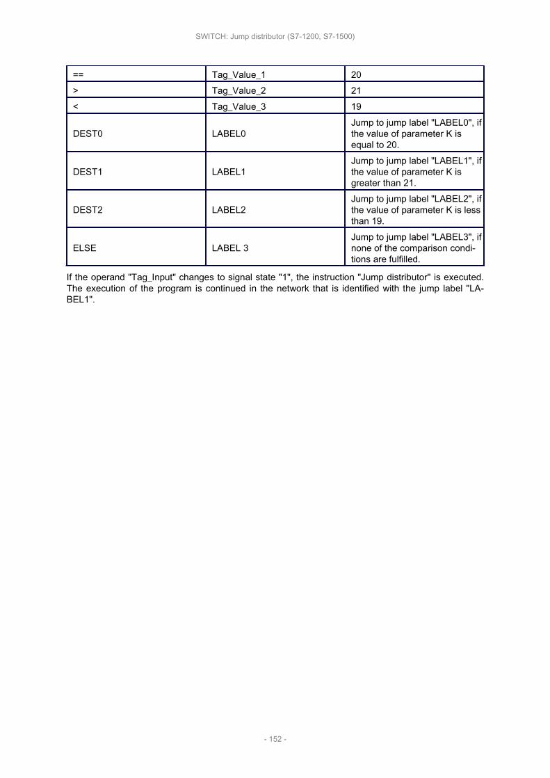
== Tag_Value_1 20> Tag_Value_2 21< Tag_Value_3 19
DEST0 LABEL0Jump to jump label "LABEL0", ifthe value of parameter K isequal to 20.
DEST1 LABEL1Jump to jump label "LABEL1", ifthe value of parameter K isgreater than 21.
DEST2 LABEL2Jump to jump label "LABEL2", ifthe value of parameter K is lessthan 19.
ELSE LABEL 3Jump to jump label "LABEL3", ifnone of the comparison condi‐tions are fulfilled.
If the operand "Tag_Input" changes to signal state "1", the instruction "Jump distributor" is executed.The execution of the program is continued in the network that is identified with the jump label "LA‐BEL1".
SWITCH: Jump distributor (S7-1200, S7-1500)
- 152 -
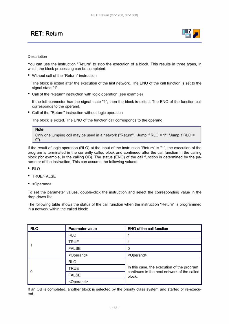
RET: RET: RET: RET: ReturnReturnReturnReturn
Description
You can use the instruction "Return" to stop the execution of a block. This results in three types, inwhich the block processing can be completed:
• Without call of the "Return" instruction
The block is exited after the execution of the last network. The ENO of the call function is set to thesignal state "1".• Call of the "Return" instruction with logic operation (see example)
If the left connector has the signal state "1", then the block is exited. The ENO of the function callcorresponds to the operand.• Call of the "Return" instruction without logic operation
The block is exited. The ENO of the function call corresponds to the operand.
NoteNoteNoteNoteOnly one jumping coil may be used in a network ("Return", "Jump if RLO = 1", "Jump if RLO =0").
If the result of logic operation (RLO) at the input of the instruction "Return" is "1", the execution of theprogram is terminated in the currently called block and continued after the call function in the callingblock (for example, in the calling OB). The status (ENO) of the call function is determined by the pa‐rameter of the instruction. This can assume the following values:
• RLO
• TRUE/FALSE
• <Operand>
To set the parameter values, double-click the instruction and select the corresponding value in thedrop-down list.
The following table shows the status of the call function when the instruction "Return" is programmedin a network within the called block:
RLORLORLORLO Parameter Parameter Parameter Parameter valuevaluevaluevalue ENO ENO ENO ENO of of of of the the the the call call call call functionfunctionfunctionfunction
1
RLO 1TRUE 1FALSE 0<Operand> <Operand>
0
RLOIn this case, the execution of the programcontinues in the next network of the calledblock.
TRUEFALSE<Operand>
If an OB is completed, another block is selected by the priority class system and started or re-execu‐ted.
RET: Return (S7-1200, S7-1500)
- 153 -

• If the OB program cycle was completed, it is restarted.
• If an OB, which interrupted another block (e.g. an Alarm OB), is completed, then the interruptedblock (e.g. OB program cycle) is executed.
ParametersParametersParametersParametersThe following table shows the parameters of the instruction "Return":
ParametersParametersParametersParameters DeclarationDeclarationDeclarationDeclaration Data Data Data Data typetypetypetype Memory Memory Memory Memory areaareaareaarea DescriptionDescriptionDescriptionDescriptionStatus of the call‐ing function whenRLO = 1:
RLO - - - Is set to the signalstate of the RLO.
TRUE - - - 1FALSE - - - 0
<Operand> Input BOOL I, Q, M, D, L Signal state of thespecified operand
ExampleExampleExampleExampleThe following example shows how the instruction works:
If the operands "TagIn_1" or "TagIn_2" have signal state "1", the instruction "Return" is executed. Pro‐gram execution in the called block is terminated and continues in the calling block. The enable outputENO of the call function is reset to signal state "0".
RET: Return (S7-1200, S7-1500)
- 154 -
Word Word Word Word logic logic logic logic operationsoperationsoperationsoperations
This chapter contains the following information:
• AND: AND: AND: AND: AND AND AND AND logic logic logic logic operation operation operation operation (S7-1200, (S7-1200, (S7-1200, (S7-1200, S7-1500)S7-1500)S7-1500)S7-1500)
• OR: OR: OR: OR: OR OR OR OR logic logic logic logic operation operation operation operation (S7-1200, (S7-1200, (S7-1200, (S7-1200, S7-1500)S7-1500)S7-1500)S7-1500)
• XOR: XOR: XOR: XOR: EXCLUSIVE EXCLUSIVE EXCLUSIVE EXCLUSIVE OR OR OR OR logic logic logic logic operation operation operation operation (S7-1200, (S7-1200, (S7-1200, (S7-1200, S7-1500)S7-1500)S7-1500)S7-1500)
• INV: INV: INV: INV: Create Create Create Create ones ones ones ones complement complement complement complement (S7-1200, (S7-1200, (S7-1200, (S7-1200, S7-1500)S7-1500)S7-1500)S7-1500)
• DECO: DECO: DECO: DECO: Decode Decode Decode Decode (S7-1200, (S7-1200, (S7-1200, (S7-1200, S7-1500)S7-1500)S7-1500)S7-1500)
• ENCO: ENCO: ENCO: ENCO: Encode Encode Encode Encode (S7-1200, (S7-1200, (S7-1200, (S7-1200, S7-1500)S7-1500)S7-1500)S7-1500)
• SEL: SEL: SEL: SEL: Select Select Select Select (S7-1200, (S7-1200, (S7-1200, (S7-1200, S7-1500)S7-1500)S7-1500)S7-1500)
• MUX: MUX: MUX: MUX: Multiplex Multiplex Multiplex Multiplex (S7-1200, (S7-1200, (S7-1200, (S7-1200, S7-1500)S7-1500)S7-1500)S7-1500)
• DEMUX: DEMUX: DEMUX: DEMUX: Demultiplex Demultiplex Demultiplex Demultiplex (S7-1200, (S7-1200, (S7-1200, (S7-1200, S7-1500)S7-1500)S7-1500)S7-1500)
Word logic operations (S7-1200, S7-1500)
- 155 -

AND: AND: AND: AND: AND AND AND AND logic logic logic logic operationoperationoperationoperation
Description
You can use the instruction "AND logic operation" to link the value at input IN1 to the value at inputIN2 bit-by-bit by AND logic and query the result at the output OUT.
When the instruction is executed, bit 0 of the value at input IN1 is linked by AND logic to bit 0 of thevalue at input IN2. The result is stored in bit 0 of output OUT. The same logic operation is executedfor all other bits of the specified values.
In its initial state the instruction box contains at least 2 inputs (IN1 and IN2). The number of inputs canbe extended. The inserted inputs are numbered in ascending order in the box. During the execution ofthe instruction, the values of all available input parameters are linked by AND logic. The result is stor‐ed at output "OUT".
The result bit has the signal state "1" only when both of the bits in the logic operation also have signalstate "1". If one of the two bits of the logic operation has signal state "0", the corresponding result bitis reset.
ParametersParametersParametersParametersThe following table shows the parameters of the instruction "AND logic operation":
ParametersParametersParametersParameters DeclarationDeclarationDeclarationDeclaration Data Data Data Data typetypetypetype Memory Memory Memory Memory areaareaareaarea DescriptionDescriptionDescriptionDescriptionS7-1200S7-1200S7-1200S7-1200 S7-1500S7-1500S7-1500S7-1500
EN Input BOOL I, Q, M, D, L I, Q, M, D, L,T, C Enable input
ENO Output BOOL I, Q, M, D, L I, Q, M, D, L Enable output
IN1 Input Bit strings I, Q, M, D, L, Por constant
I, Q, M, D, L, Por constant
First value forlogic operation
IN2 Input Bit strings I, Q, M, D, L, Por constant
I, Q, M, D, L, Por constant
Second valuefor logic opera‐tion
INn Input Bit strings I, Q, M, D, L, Por constant
I, Q, M, D, L, Por constant
Optional inputvalues
OUT Output Bit strings I, Q, M, D, L, P I, Q, M, D, L, P Result of theinstruction
You can select the data type of the instruction from the "<???>" drop-down list of the instruction box.
For additional information on valid data types, refer to "See also".
ExampleExampleExampleExampleThe following example shows how the instruction works:
AND: AND logic operation (S7-1200, S7-1500)
- 156 -

The following table shows how the instruction works using specific operand values:
ParametersParametersParametersParameters OperandOperandOperandOperand ValueValueValueValueIN1 Tag_Value1 0101 0101 0101 0101IN2 Tag_Value2 0000 0000 0000 1111OUT Tag_Result 0000 0000 0000 0101
If the operand "TagIn" has the signal state "1", the instruction "AND logic operation" is executed. Thevalue of operand "Tag_Value1" is linked by AND to the value of the operand "Tag_Value2". The resultis mapped bit-for-bit and sent to the operand "Tag_Result". The enable output ENO and the output"TagOut" are set to signal state "1".
AND: AND logic operation (S7-1200, S7-1500)
- 157 -

OR: OR: OR: OR: OR OR OR OR logic logic logic logic operationoperationoperationoperation
Description
You can use the instruction "OR logic operation" to link the value at input IN1 to the value at input IN2bit-by-bit by OR logic and query the result at the output OUT.
When the instruction is executed, bit 0 of the value at input IN1 is linked by OR logic to bit 0 of thevalue at input IN2. The result is stored in bit 0 of output OUT. The same logic operation is executedfor all bits of the specified tags.
In its initial state the instruction box contains at least 2 inputs (IN1 and IN2). The number of inputs canbe extended in the instruction box. The inserted inputs are numbered in ascending order in the box.During the execution of the instruction, the values of all available input parameters are linked by ORlogic. The result is stored at output "OUT".
The result bit has the signal state "1" when at least one of the two bits in the logic operation has thesignal state "1". If both of the bits of the logic operation have signal state "0", the corresponding resultbit is reset.
ParametersParametersParametersParametersThe following table shows the parameters of the instruction "OR logic operation":
ParametersParametersParametersParameters DeclarationDeclarationDeclarationDeclaration Data Data Data Data typetypetypetype Memory Memory Memory Memory areaareaareaarea DescriptionDescriptionDescriptionDescriptionS7-1200S7-1200S7-1200S7-1200 S7-1500S7-1500S7-1500S7-1500
EN Input BOOL I, Q, M, D, L I, Q, M, D, L,T, C Enable input
ENO Output BOOL I, Q, M, D, L I, Q, M, D, L Enable output
IN1 Input Bit strings I, Q, M, D, L, Por constant
I, Q, M, D, L, Por constant
First value forlogic operation
IN2 Input Bit strings I, Q, M, D, L, Por constant
I, Q, M, D, L, Por constant
Second valuefor logic opera‐tion
INn Input Bit strings I, Q, M, D, L, Por constant
I, Q, M, D, L, Por constant
Optional inputvalues
OUT Output Bit strings I, Q, M, D, L, P I, Q, M, D, L, P Result of theinstruction
You can select the data type of the instruction from the "<???>" drop-down list of the instruction box.
For additional information on valid data types, refer to "See also".
ExampleExampleExampleExampleThe following example shows how the instruction works:
OR: OR logic operation (S7-1200, S7-1500)
- 158 -

The following table shows how the instruction works using specific operand values:
ParametersParametersParametersParameters OperandOperandOperandOperand ValueValueValueValueIN1 Tag_Value1 0101 0101 0101 0101IN2 Tag_Value2 0000 0000 0000 1111OUT Tag_Result 0101 0101 0101 1111
If the operand "TagIn" has the signal state "1", the instruction "OR logic operation" is executed. Thevalue of operand "Tag_Value1" is linked by OR to the value of the operand "Tag_Value2". The resultis mapped bit-for-bit and sent to the operand "Tag_Result". The enable output ENO and the output"TagOut" are set to signal state "1".
OR: OR logic operation (S7-1200, S7-1500)
- 159 -

Shift Shift Shift Shift and and and and rotaterotaterotaterotate
This chapter contains the following information:
• SHR: SHR: SHR: SHR: Shift Shift Shift Shift right right right right (S7-1200, (S7-1200, (S7-1200, (S7-1200, S7-1500)S7-1500)S7-1500)S7-1500)
• SHL: SHL: SHL: SHL: Shift Shift Shift Shift left left left left (S7-1200, (S7-1200, (S7-1200, (S7-1200, S7-1500)S7-1500)S7-1500)S7-1500)
• ROR: ROR: ROR: ROR: Rotate Rotate Rotate Rotate right right right right (S7-1200, (S7-1200, (S7-1200, (S7-1200, S7-1500)S7-1500)S7-1500)S7-1500)
• ROL: ROL: ROL: ROL: Rotate Rotate Rotate Rotate left left left left (S7-1200, (S7-1200, (S7-1200, (S7-1200, S7-1500)S7-1500)S7-1500)S7-1500)
Shift and rotate (S7-1200, S7-1500)
- 160 -

SHR: SHR: SHR: SHR: Shift Shift Shift Shift rightrightrightright
Description
You can use the "Shift right" instruction to shift the content of the operand at the input IN bit-by-bit tothe right and query the result at the OUT output. The input N is used to specify the number of bit posi‐tions by which the specified value should be moved.
If the value at the input N is "0", the value at input IN is copied unchanged to the operand at outputOUT.
If the value at the input N is greater than the number of available bit positions, the operand value atinput IN is shifted to the right by the available number of bit positions.
The freed bit positions in the left area of the operand are filled by zeroes when values without signsare shifted. If the specified value has a sign, the free bit positions are filled with the signal state of thesign bit.
The following figure show how the content of an integer data type operand is shifted four bit positionsto the right:
ParametersParametersParametersParametersThe following table shows the parameters of the instruction "Shift right":
ParameterParameterParameterParameter DeclarationDeclarationDeclarationDeclaration Data Data Data Data typetypetypetype Memory Memory Memory Memory areaareaareaarea DescriptionDescriptionDescriptionDescriptionS7-1200S7-1200S7-1200S7-1200 S7-1500S7-1500S7-1500S7-1500 S7-1200S7-1200S7-1200S7-1200 S7-1500S7-1500S7-1500S7-1500
EN Input BOOL BOOL I, Q, M, D, L I, Q, M, D, L,T, C Enable input
ENO Output BOOL BOOL I, Q, M, D, L I, Q, M, D, L Enable out‐put
SHR: Shift right (S7-1200, S7-1500)
- 161 -

IN Input Bit strings,integers
Bit strings,integers
I, Q, M, D, Lor constant
I, Q, M, D, Lor constant
Value to beshifted
N InputUSINT,UINT,UDINT
USINT,UINT,UDINT,ULINT
I, Q, M, D, Lor constant
I, Q, M, D, Lor constant
Number ofbit positionsby which thevalue is shif‐ted
OUT Output Bit strings,integers
Bit strings,integers I, Q, M, D, L I, Q, M, D, L Result of the
instruction
You can select the data type for the instruction from the "<???>" drop-down list of the instruction box.
For additional information on valid data types, refer to "See also".
ExampleExampleExampleExampleThe following example shows how the instruction works:
The following table shows how the instruction works using specific operand values:
ParameterParameterParameterParameter OperandOperandOperandOperand ValueValueValueValueIN TagIn_Value 0011 1111 1010 1111N Tag_Number 3OUT TagOut_Value 0000 0111 1111 0101
If the operand "TagIn" has the signal state "1", the instruction "Shift right" is executed. The content ofthe operand "TagIn_Value" is shifted three bit positions to the right. The result is sent at output "Tag‐Out_Value". If the instruction is executed without errors, the ENO enable output has the signal state"1" and the "TagOut" output is set.
SHR: Shift right (S7-1200, S7-1500)
- 162 -

SHL: SHL: SHL: SHL: Shift Shift Shift Shift leftleftleftleft
Description
You can use the "Shift left" instruction to shift the content of the operand at the input IN bit-by-bit tothe left and query the result at the OUT output. The input N is used to specify the number of bit posi‐tions by which the specified value should be moved.
If the value at the input N is "0", the value at input IN is copied unchanged to the operand at outputOUT.
If the value at the input N is greater than the number of available bit positions, the operand value atinput IN is shifted to the left by the available number of bit positions.
The bit positions in the right part of the operand freed by shifting are filled with zeros.
The following figure show how the content of an operand of the data type WORD is shifted six bit po‐sitions to the left:
ParametersParametersParametersParametersThe following table shows the parameters of the instruction "Shift left":
ParameterParameterParameterParameter DeclarationDeclarationDeclarationDeclaration Data Data Data Data typetypetypetype Memory Memory Memory Memory areaareaareaarea DescriptionDescriptionDescriptionDescriptionS7-1200S7-1200S7-1200S7-1200 S7-1500S7-1500S7-1500S7-1500 S7-1200S7-1200S7-1200S7-1200 S7-1500S7-1500S7-1500S7-1500
EN Input BOOL BOOL I, Q, M, D, L I, Q, M, D, L,T, C Enable input
ENO Output BOOL BOOL I, Q, M, D, L I, Q, M, D, L Enable out‐put
IN Input Bit strings,integers
Bit strings,integers
I, Q, M, D, Lor constant
I, Q, M, D, Lor constant
Value to beshifted.
SHL: Shift left (S7-1200, S7-1500)
- 163 -

N InputUSINT,UINT,UDINT
USINT,UINT,UDINT,ULINT
I, Q, M, D, Lor constant
I, Q, M, D, Lor constant
Number ofbit positionsby which thevalue is shif‐ted.
OUT Output Bit strings,integers
Bit strings,integers I, Q, M, D, L I, Q, M, D, L Result of the
instruction
You can select the data type for the instruction from the "<???>" drop-down list of the instruction box.
For additional information on valid data types, refer to "See also".
ExampleExampleExampleExampleThe following example shows how the instruction works:
The following table shows how the instruction works using specific operand values:
ParameterParameterParameterParameter OperandOperandOperandOperand ValueValueValueValueIN TagIn_Value 0011 1111 1010 1111N Tag_Number 4OUT TagOut_Value 1111 1010 1111 0000
If the operand "TagIn" has the signal state "1", the instruction "Shift left" is executed. The content ofthe operand "TagIn_Value" is shifted four bit positions to the left. The result is sent at output "Tag‐Out_Value". If the instruction is executed without errors, the ENO enable output has the signal state"1" and the "TagOut" output is set.
SHL: Shift left (S7-1200, S7-1500)
- 164 -

ROR: ROR: ROR: ROR: Rotate Rotate Rotate Rotate rightrightrightright
Description
You can use the "Rotate right" instruction to rotate the content of the operand at the input IN bit-by-bitto the right and query the result at the OUT output. The input N is used to specify the number of bitpositions by which the specified value should be rotated. The bit positions freed by rotating on the left-hand side are filled true-to-position with the bit positions that are pushed out from the left-hand side.
If the value at the input N is "0", the value at input IN is copied unchanged to the operand at outputOUT.
If the value at the parameter N is greater than the number of available bit positions, the operand valueat input IN is nevertheless rotated by the specified number of bit positions.
The following figure shows how the content of an operand of the data type DWORD is rotated threebit positions to the right:
ParametersParametersParametersParametersThe following table shows the parameters of the instruction "Rotate right":
ParameterParameterParameterParameter DeclarationDeclarationDeclarationDeclaration Data Data Data Data typetypetypetype Memory Memory Memory Memory areaareaareaarea DescriptionDescriptionDescriptionDescriptionS7-1200S7-1200S7-1200S7-1200 S7-1500S7-1500S7-1500S7-1500 S7-1200S7-1200S7-1200S7-1200 S7-1500S7-1500S7-1500S7-1500
EN Input BOOL BOOL I, Q, M, D, L I, Q, M, D, L,T, C Enable input
ENO Output BOOL BOOL I, Q, M, D, L I, Q, M, D, L Enable out‐put
IN Input Bit strings,integers
Bit strings,integers
I, Q, M, D, Lor constant
I, Q, M, D, Lor constant
Value to berotated
ROR: Rotate right (S7-1200, S7-1500)
- 165 -

N InputUSINT,UINT,UDINT
USINT,UINT,UDINT,ULINT
I, Q, M, D, Lor constant
I, Q, M, D, Lor constant
Number ofbit positionsby which thevalue is rota‐ted
OUT Output Bit strings,integers
Bit strings,integers I, Q, M, D, L I, Q, M, D, L Result of the
instruction
You can select the data type for the instruction from the "<???>" drop-down list of the instruction box.
For additional information on valid data types, refer to "See also".
ExampleExampleExampleExampleThe following example shows how the instruction works:
The following table shows how the instruction works using specific operand values:
ParameterParameterParameterParameter OperandOperandOperandOperand ValueValueValueValueIN TagIn_Value 0000 1111 1001 0101N Tag_Number 5OUT TagOut_Value 1010 1000 0111 1100
If the operand "TagIn" has the signal state "1", the instruction "Rotate right" is executed. The contentof the operand "TagIn_Value" is rotated five bit positions to the right. The result is sent at output "Tag‐Out_Value". If the instruction is executed without errors, the ENO enable output has the signal state"1" and the "TagOut" output is set.
ROR: Rotate right (S7-1200, S7-1500)
- 166 -

ROL: ROL: ROL: ROL: Rotate Rotate Rotate Rotate leftleftleftleft
Description
You can use the "Rotate left" instruction to rotate the content of the operand at the input IN bit-by-bitto the left and query the result at the OUT output. The input N is used to specify the number of bitpositions by which the specified value should be rotated. The bit positions freed by rotating on theright-hand side are filled true-to-position with the bit positions that are pushed out from the left-handside.
If the value at the input N is "0", the value at input IN is copied to the operand at output OUT.
If the value at the parameter N is greater than the number of available bit positions, the operand valueat input IN is nevertheless rotated by the specified number of bit positions.
The following figure shows how the content of an operand of the data type DWORD is rotated threebit positions to the left:
ParametersParametersParametersParametersThe following table shows the parameters of the instruction "Rotate left":
ParameterParameterParameterParameter DeclarationDeclarationDeclarationDeclaration Data Data Data Data typetypetypetype Memory Memory Memory Memory areaareaareaarea DescriptionDescriptionDescriptionDescriptionS7-1200S7-1200S7-1200S7-1200 S7-1500S7-1500S7-1500S7-1500 S7-1200S7-1200S7-1200S7-1200 S7-1500S7-1500S7-1500S7-1500
EN Input BOOL BOOL I, Q, M, D, L I, Q, M, D, L,T, C Enable input
ENO Output BOOL BOOL I, Q, M, D, L I, Q, M, D, L Enable out‐put
IN Input Bit strings,integers
Bit strings,integers
I, Q, M, D, Lor constant
I, Q, M, D, Lor constant
Value to berotated.
ROL: Rotate left (S7-1200, S7-1500)
- 167 -
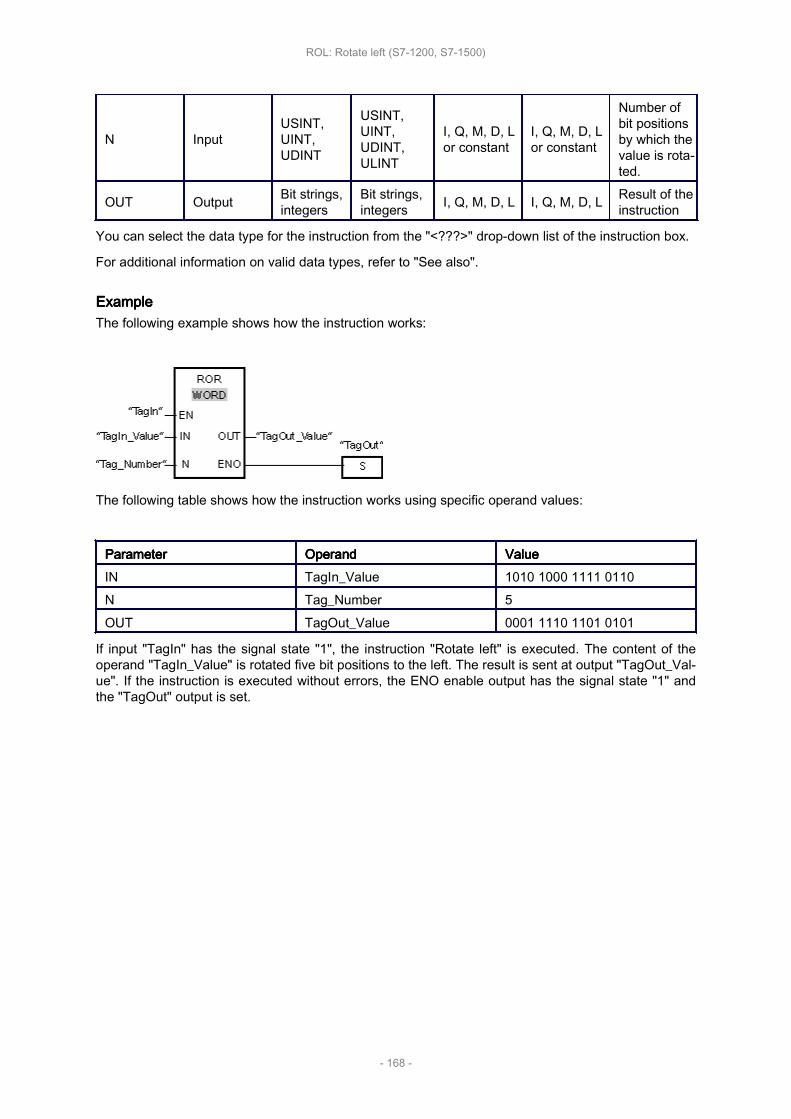
N InputUSINT,UINT,UDINT
USINT,UINT,UDINT,ULINT
I, Q, M, D, Lor constant
I, Q, M, D, Lor constant
Number ofbit positionsby which thevalue is rota‐ted.
OUT Output Bit strings,integers
Bit strings,integers I, Q, M, D, L I, Q, M, D, L Result of the
instruction
You can select the data type for the instruction from the "<???>" drop-down list of the instruction box.
For additional information on valid data types, refer to "See also".
ExampleExampleExampleExampleThe following example shows how the instruction works:
The following table shows how the instruction works using specific operand values:
ParameterParameterParameterParameter OperandOperandOperandOperand ValueValueValueValueIN TagIn_Value 1010 1000 1111 0110N Tag_Number 5OUT TagOut_Value 0001 1110 1101 0101
If input "TagIn" has the signal state "1", the instruction "Rotate left" is executed. The content of theoperand "TagIn_Value" is rotated five bit positions to the left. The result is sent at output "TagOut_Val‐ue". If the instruction is executed without errors, the ENO enable output has the signal state "1" andthe "TagOut" output is set.
ROL: Rotate left (S7-1200, S7-1500)
- 168 -
Additional Additional Additional Additional instructionsinstructionsinstructionsinstructions
This chapter contains the following information:
• DRUM: DRUM: DRUM: DRUM: Implement Implement Implement Implement sequencer sequencer sequencer sequencer (S7-1500)(S7-1500)(S7-1500)(S7-1500)
• DCAT: DCAT: DCAT: DCAT: Discrete Discrete Discrete Discrete control-timer control-timer control-timer control-timer alarm alarm alarm alarm (S7-1500)(S7-1500)(S7-1500)(S7-1500)
• MCAT: MCAT: MCAT: MCAT: Motor Motor Motor Motor control-timer control-timer control-timer control-timer alarm alarm alarm alarm (S7-1500)(S7-1500)(S7-1500)(S7-1500)
• IMC: IMC: IMC: IMC: Compare Compare Compare Compare input input input input bits bits bits bits with with with with the the the the bits bits bits bits of of of of a a a a mask mask mask mask (S7-1500)(S7-1500)(S7-1500)(S7-1500)
• SMC: SMC: SMC: SMC: Compare Compare Compare Compare scan scan scan scan matrix matrix matrix matrix (S7-1500)(S7-1500)(S7-1500)(S7-1500)
• LEAD_LAG: LEAD_LAG: LEAD_LAG: LEAD_LAG: Lead Lead Lead Lead and and and and lag lag lag lag algorithm algorithm algorithm algorithm (S7-1500)(S7-1500)(S7-1500)(S7-1500)
• SEG: SEG: SEG: SEG: Create Create Create Create bit bit bit bit pattern pattern pattern pattern for for for for seven-segment seven-segment seven-segment seven-segment display display display display (S7-1500)(S7-1500)(S7-1500)(S7-1500)
• BCDCPL: BCDCPL: BCDCPL: BCDCPL: Create Create Create Create tens tens tens tens complement complement complement complement (S7-1500)(S7-1500)(S7-1500)(S7-1500)
• BITSUM: BITSUM: BITSUM: BITSUM: Count Count Count Count number number number number of of of of set set set set bits bits bits bits (S7-1500)(S7-1500)(S7-1500)(S7-1500)
Additional instructions (S7-1500)
- 169 -

DRUM: DRUM: DRUM: DRUM: Implement Implement Implement Implement sequencersequencersequencersequencer
Description
You can use the "Implement sequencer" instruction to assign the programmed values of theOUT_VAL parameter of the corresponding step to the programmed output bits (OUT1 to OUT16) andthe output word (OUT_WORD). The specific step must thereby satisfy the conditions of the program‐med enable mask on the S_MASK parameter while the instruction remains at this step. The instruc‐tion advances to the next step if the event for the step is true and the programmed time for the currentstep elapses or if the value at the JOG parameter changes from "0" to "1". The instruction is reset ifthe signal state on the RESET parameter changes to "1". The current step is hereby equated to thepreset step (DSP).
The amount of time spent on a step is determined by the product of the preset timebase (DTBP) andthe preset counter value (S_PRESET) for each step. At the start of a new step, this calculated value isloaded into the DCC parameter, which contains the time remaining for the current step. If, for examplethe value of the DTBP parameter is "2" and the preset value for the first step is "100" (100 ms), theDCC parameter has the value "200" (200 ms).
A step can be programmed with a timer value, an event or both. Steps that have an event bit and thetimer value "0" advance to the next step as soon as the signal state of the event bit is "1". Steps thatare programmed only with a timer value start the time immediately. Steps that are programmed withan event bit and a timer value greater than "0" start the time when the signal state of the event bit is"1". The event bits are initialized with a signal state of "1".
When the sequencer is on the last programmed step (LST_STEP) and the time for this step has ex‐pired, the signal state on the Q parameter is set to "1"; otherwise it is set to "0". When the Q parame‐ter is set, the instruction remains on the step until it is reset.
In the configurable mask (S_MASK), you can selected the individual bits in the output word(OUT_WORD) and set or reset the output bits (OUT1 to OUT16) by means of the output values(OUT_VAL). If a bit of the configurable mask has signal state "1", the OUT_VAL value sets or resetsthe corresponding bit. If the signal state of a bit of the configurable mask is "0", the corresponding bitis left unchanged. All the bits of the configurable mask for all 16 steps are initialized with a signal stateof "1".
The output bit at the OUT1 parameter corresponds to the least significant bit of the output word(OUT_WORD). The output bit at the OUT16 parameter corresponds to the most significant bit of theoutput word (OUT_WORD).
When you insert the instruction in the program, the "Call options" dialog opens in which you can spec‐ify whether the block parameters will be stored in a separate data block (single instance) or as a localtag (multiple instance) in the block interface. If you create a separate data block, you will find it in theproject tree in the "Program resources" folder under "Program blocks > System blocks". For additionalinformation on this topic, refer to "See also".
ParametersParametersParametersParametersThe following table shows the parameters of the "Implement sequencer" instruction:
ParameterParameterParameterParameter DeclarationDeclarationDeclarationDeclaration Data Data Data Data typetypetypetype Memory Memory Memory Memory areaareaareaarea DescriptionDescriptionDescriptionDescriptionEN Input BOOL I, Q, M, D, L, T, C Enable inputENO Output BOOL I, Q, M, D, L Enable output
DRUM: Implement sequencer (S7-1500)
- 170 -

RESET Input BOOL I, Q, M, D, L orconstant
The signal state"1" indicates thereset condition.
JOG Input BOOL I, Q, M, D, L orconstant
When the signalstate changesfrom "0" to "1", theinstruction advan‐ces to the nextstep.
DRUM_EN Input BOOL I, Q, M, D, L orconstant
The signal state"1" causes the se‐quencer to ad‐vance based onthe event and timecriteria.
LST_STEP Input BYTE I, Q, M, D, L orconstant
Number of the lastprogrammed step
EVENT(i),
1 ≤ i ≤ 16Input BOOL I, Q, M, D, L or
constant
Event bit (i);
Initial signal stateis "1".
OUT(j),
1 ≤ j ≤ 16Output BOOL I, Q, M, D, L Output bit (j)
Q Output BOOL I, Q, M, D, L
The signal state"1" indicates thatthe time for thelast step haselapsed.
OUT_WORD Output WORD I, Q, M, D, L, P
Word address towhich the se‐quencer writes theoutput values.
ERR_CODE Output WORD I, Q, M, D, L, P Error information
JOG_HIS Static BOOL I, Q, M, D, L orconstant
JOG parameterhistory bit
EOD Static BOOL I, Q, M, D, L orconstant
The signal state"1" indicates thatthe time for thelast step haselapsed.
DSP Static BYTE I, Q, M, D, L, P orconstant
Preset step of thesequencer
DSC Static BYTE I, Q, M, D, L, P orconstant
Current step ofthe sequencer
DCC Static DWORD I, Q, M, D, L, P orconstant
Current numericalvalue of the se‐quencer
DTBP Static WORD I, Q, M, D, L, P orconstant
Preset timebaseof the sequencer
DRUM: Implement sequencer (S7-1500)
- 171 -
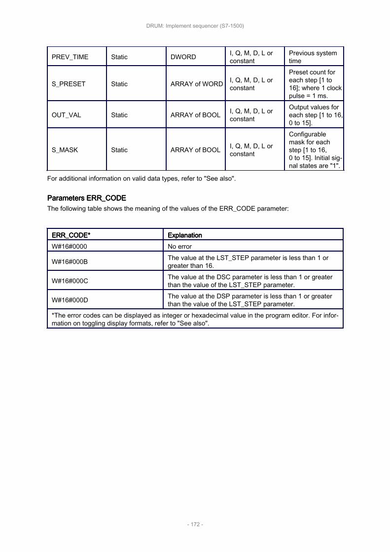
PREV_TIME Static DWORD I, Q, M, D, L orconstant
Previous systemtime
S_PRESET Static ARRAY of WORD I, Q, M, D, L orconstant
Preset count foreach step [1 to16]; where 1 clockpulse = 1 ms.
OUT_VAL Static ARRAY of BOOL I, Q, M, D, L orconstant
Output values foreach step [1 to 16,0 to 15].
S_MASK Static ARRAY of BOOL I, Q, M, D, L orconstant
Configurablemask for eachstep [1 to 16,0 to 15]. Initial sig‐nal states are "1".
For additional information on valid data types, refer to "See also".
Parameters Parameters Parameters Parameters ERR_CODEERR_CODEERR_CODEERR_CODEThe following table shows the meaning of the values of the ERR_CODE parameter:
ERR_CODE*ERR_CODE*ERR_CODE*ERR_CODE* ExplanationExplanationExplanationExplanationW#16#0000 No error
W#16#000B The value at the LST_STEP parameter is less than 1 orgreater than 16.
W#16#000C The value at the DSC parameter is less than 1 or greaterthan the value of the LST_STEP parameter.
W#16#000D The value at the DSP parameter is less than 1 or greaterthan the value of the LST_STEP parameter.
*The error codes can be displayed as integer or hexadecimal value in the program editor. For infor‐mation on toggling display formats, refer to "See also".
DRUM: Implement sequencer (S7-1500)
- 172 -