FB0254 MA O&M Manual 10-16-12 A - Joyce Dayton · P.O. Box 1630 Dayton, OH 45401 (800) 523-5204 (US...
16
Joyce/Dayton Corp. Operation and Maintenance Manual for Multipurpose Actuators 120 VAC Actuator 12 VDC Actuator 12 VDC Actuator The recommendations in this manual for installation, operation and maintenance must be followed to ensure safe use. All persons responsible for the installation and use of Joyce/Dayton Multipurpose Actuators must be familiar with the contents of this manual. The customer is responsible for guards and other protective devices and for ensuring that Multipurpose Actuator usage conforms with local and national operating and safety codes appropriate to the class of equipment into which the Multipurpose Actuator is installed. ©2012 Joyce/Dayton Corp. All rights reserved FB0254 – 10/12
Transcript of FB0254 MA O&M Manual 10-16-12 A - Joyce Dayton · P.O. Box 1630 Dayton, OH 45401 (800) 523-5204 (US...

Joyce/Dayton Corp .
Operation and Maintenance Manual for
Multipurpose Actuators
120 VAC Actuator 12 VDC Actuator 12 VDC Actuator
The recommendations in this manual for installation, operation and maintenance must be followed to ensure safe use. All persons responsible for the installation and use of Joyce/Dayton Multipurpose Actuators must be familiar with the contents of this manual.
The customer is responsible for guards and other protective devices and for ensuring that Multipurpose Actuator usage conforms with local and national operating and safety codes appropriate to the class of equipment into which the Multipurpose Actuator is installed.
©2012 Joyce/Dayton Corp. All rights reserved FB0254 – 10/12

2
Table of Contents
Section I – General Information 1-1 Contact Joyce/Dayton .......................... ............................................................................... 3 1-2 Purpose and Scope ............................. ................................................................................ 3 1-3 Receipt of Product ............................ ................................................................................... 3 1-4 Warranty ...................................... ......................................................................................... 3 1-5 Precautions for Use and Installation .......... ....................................................................... 3 1-6 Features ..................................... .......................................................................................... 4 1-7 Limit Switch Adjustment ...................... .............................................................................. 4 1-8 Wiring Instructions for Motor and Potentiometer ............................................................. 6 1-9 Mounting Guidelines (examples) ................ ....................................................................... 7
Section II – Multipurpose Actuator Drawings 2-1 (DC) MA0513 Drawing and Charts ................ ..................................................................... 8 2-2 (DC) MA1527 & MA3507 Drawing and Charts ....... ............................................................ 9 2-3 (DC) MA2547, MA3527, MA4514, MA7007 Drawing and Charts ...................................... 10 2-4 (AC) MA1527 & MA3507 Drawing and Charts ....... ............................................................ 11 2-5 (AC) MA2547, MA3527, MA4514, MA7007 Drawing and Charts ...................................... 12
Section III – Order Information 3-1 Part Number Description ....................... ............................................................................. 13 3-2 Serial Number Information ..................... ............................................................................ 13

3
Section I General Information
1-1 Contact Joyce/Dayton Corp.
Joyce/Dayton Corp. P.O. Box 1630 Dayton, OH 45401 (800) 523-5204 (US and Canada) (937) 294-6261 (937) 297-7173 Fax Email: [email protected] Website: www.joycedayton.com
1-2 Purpose and Scope This manual provides installation, operation and maintenance instruction for standard Joyce/Dayton Multipurpose Actuators. For special units not covered, please contact Joyce/Dayton Corp.
1-3 Receipt of Product
All equipment should be immediately inspected upon receipt for any damage and to verify correct product and quantities. Any problems should be reported to Joyce/Dayton Corp. and the freight carrier as soon as possible. Products returned without a Return Goods Authorization (RGA) form will not be accepted. Contact Joyce/Dayton to obtain an RGA.
1-4 Warranty Seller warrants its products to be free from defects in material and workmanship under normal and proper use in accordance with instruction of seller for a period of one year from the date of shipment to buyer. Seller's liability under such warranty or in connection with any other claim relating to the products shall be limited to the repair, or at seller’s option, the replacement or refund of the purchase price of any products or parts or components thereof which are returned to seller freight prepaid and which are defective in material or workmanship. Products or parts or components thereof, which are repaired or replaced by seller will be returned to buyer freight collect. This warranty is not intended to cover consumer products, as defined in the Magnuson-Moss Warranty-Federal Trade Commission Improvement Act, 15 U. S. C. Sections 2301-12, which are purchased by buyer for purposes other than resale. If buyer is not intending to resell the products, and if the products are consumer products as defined in the Magnuson-Moss Act, the foregoing warranty, but not the limitation of seller's liability, shall be null and void. EXCEPT AS EXPRESSLY STATED ABOVE, SELLER MAKES NO WARRANTY, EXPRESS OR IMPLIED, WHETHER OF MERCHANTABILITY OR FITNESS FOR ANY PARTICULAR PURPOSE OR USE OR OTHERWISE, ON THE PRODUCTS, OR ON ANY PARTS OR LABOR FURNISHED DURING THE SALE, DELIVERY OR SERVICING OF THE PRODUCTS.
1-5 Precautions of Use and Installation
1. Each Multipurpose Actuator includes limit switches, which are preset to the design limits of the unit. Customers who choose to make limit switch position adjustments must ensure the limits remain within the design limits of the actuator. Note that adjustments to the preset positions need to be made before the actuator is installed. Limit switches on MA0513 are not adjustable.
2. It is necessary that appropriate, qualified personnel perform the installation of Joyce/Dayton products. Ensure that all personnel who will service or operate equipment are familiar with its use and limitations.
3. Joyce/Dayton Multipurpose Actuators are not rated for shock-loading or extreme vibration. It is the responsibility of the user to ensure these conditions are not imposed on the actuator.
4. In the event that service or maintenance is required, the load must be secured or removed before any work can begin.

4
5. Multipurpose actuators can be mounted and operated in any orientation, but the load must be axial to the actuator. No side load is permitted. Refer to Section 1-9 for installation guidelines.
6. Be certain the rating of the actuator meets or exceeds the load. 7. The actuator must be mounted on a rigid structure sufficient to support the maximum possible
load. An under-designed structure could lead to premature wear or failure. 8. When fastening the load to an actuator, make sure the actuator is in the retracted position.
This positions the load accurately with respect to the lifting screw centerline. Never pull the translating tube to one side to make connection with your structure. Fully extend the actuator to make sure the load is aligned with the translating tube.
1-6 Features 12 VDC Multipurpose Actuator
• 12 volt DC motor • Preset limit switches (Adjustable, except for MA0513, which are not adjustable) • Self-locking • Potentiometer • Clevis-to-Clevis Mounting Style • 25% duty cycle • IP65 protection rating
120 VAC Multipurpose Actuators
• 120 volt AC motor • Preset limit switches (Adjustable) • Self-locking • Potentiometer • Clevis-to-Clevis Mounting Style • 25% duty cycle • IP65 protection rating
1-7 Limit Switch Adjustment Limit switches on all Multipurpose Actuators are preset. These instructions are provided in
case the preset positions need to be adjusted. Limit switches on MA0513 actuators are not adjustable. Figure 1 and Figure 2 on the following page illustrate the limit switch components. Exercise reasonable precaution when making adjustments. Do not contact the inner tube while the motor is running.
1. If the actuator is not already fully retracted (ref. catalog for minimum closed height)
operate the actuator until the lower limit is reached and the motor stops. If satisfied with the actuator retract dimension as positioned continue to step # 3.
2. To finely position the retract stopping location rotate the inner actuator tube until the desired stopping location is achieved. Do not rotate the inner tube in a manner to position it lower than the minimum closed height shown in the catalog.
3. From this point on until the actuator is fully mounted in the assembly it is important not to allow the inner tube to rotate. Allowing it to rotate will alter the retracted position location and require repeating steps 1 & 2.

5
4. To set the upper limit switch position, secure the inner tube from rotating by either gripping it by hand or slide a screwdriver through the clevis hole and lay the actuator down flat on a suitable work surface.
5. Electrically operate the actuator until the desired extend position is reached. If the actuator stops on its own before reaching the desired position the retract position may have been set too high and the physical travel limitations of the actuator have been exceeded. To rectify this problem repeat steps 1 & 2 or modify your assembly/structure geometry.
6. Once the desired extend position is reached. Use an Allen wrench to remove the five hex head cap screws at the base of the actuator housing, and gently pull the limit switch cover off the housing. It may be necessary to straighten the wires in the pigtail to facilitate separation. This will expose the limit switch assembly.
7. Loosen the Philips-head screw on the limit switch cam assembly just enough so the upper cam can separate from the lower cam but not enough where the screw is removed completely. Adjust the upper cam by simultaneously pulling gently away from the lower cam and rotate until the upper cam just depresses the extend limit switch plunger. Take care not to disturb the position of the lower cam and gear.
8. Tighten the Philips-head screw and if desired electrically retract the actuator to confirm the retracted dimension and extend to confirm the fully extended position. If satisfied continue to the next step otherwise repeat the instructions outlined above.
9. Carefully replace the cover, taking care that the gasket is in place and the wires remain tucked inside the cover. Tighten the five socket head cap screws to fasten the cover in place.
10. Once the limit switches are set, the unit can be mounted into the assembly.
Figure 1 – Limit Switch Schematic Figure 2 – View of Limit Switch Inside Housing

6
1-8 Wiring Instructions for Motor and Potentiometer
12 VDC Motor - MA0513 The actuator will extend when the red wire connects to the positive lead and the black wire
connects to the negative lead. It will retract when the black wire connects to the positive lead the red wire connects to the negative lead. See Figure 3 below.
Figure 3 – Motor Schematic MA0513 12 VDC Motor - MA1527, MA2547, MA3507, MA3527, MA45 14, MA7007 The actuator will extend when the red wire connects to the positive lead and the black wire connects to the negative lead. It will retract when the black wire connects to the positive lead the red wire connects to the negative lead. See Figure 4 below.
Figure 4 – 12 VDC Motor Schematic MA1527, MA2547, MA3507, MA3527, MA4514, MA7007
120 VAC Motor - MA1527, MA2547, MA3507, MA3527, MA4 514, MA7007 The AC actuator will extend when the red wire connects to the white lead. It will retract when the red wire connects to the black lead. See Figure 5 below.
Figure 5 – 120 VAC Motor Schematic

7
Potentiometer (for 12 VDC and 120 VAC Actuators) The potentiometer has a 0 -10 K Ohm resistance range. The actual resistance value is a variable that is based on the stroke length. It is measured between the blue and white wires. Values have a +/-0.3 K Ohm tolerance. Refer to the Figure 6 for the potentiometer schematic.
Ohm value between blue & white wire
Stroke (mm)
Approximate Resistance (Ohm)
100 0.3 – 8.0 K
150 or 153 0.3 – 8.5 K
200 0.3 – 9.1 K
300 or 305 0.3 – 8.6 K
457 0.3 – 9.2 K
Tolerance ±0.3K
Figure 6 – Potentiometer schematic Figure 7 – Resistance values
Yellow White Black
Figure 8 – DC Wiring Figure 9 – AC Wiring 1-9 Mounting Guidelines Installation Guidelines The actuator can be mounted in any orientation but the load should be attached to the actuator and
mounted axially so no side load is imposed on the actuator. Figure 10 below shows an axial load in a horizontal plane. Vertical loads can also be mounted axially.
Figure 10 –Example of Axial Load Figure 11 illustrates a horizontal side load, but it is also possible to impose a side load on a vertically mounted actuator. Side loading is not recommended in any orientation.
Figure 11 – Example of Side Load - NOT recommended
8
Section II Multipurpose Actuator Drawings
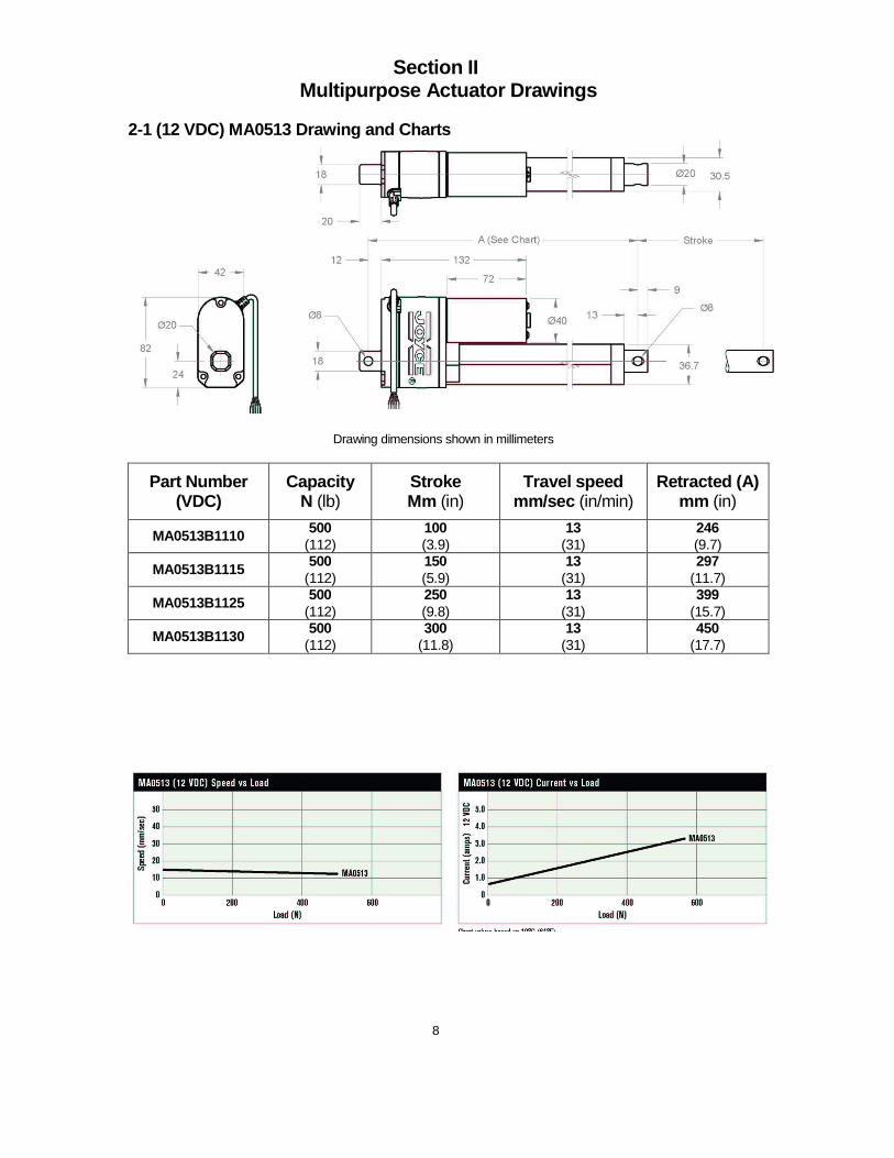
2-1 (12 VDC) MA0513 Drawing and Charts
Drawing dimensions shown in millimeters
Part Number (VDC)
Capacity N (lb)
Stroke Mm (in)
Travel speed mm/sec (in/min)
Retracted (A) mm (in)
MA0513B1110 500 (112)
100 (3.9)
13 (31)
246 (9.7)
MA0513B1115 500 (112)
150 (5.9)
13 (31)
297 (11.7)
MA0513B1125 500 (112)
250 (9.8)
13 (31)
399 (15.7)
MA0513B1130 500 (112)
300 (11.8)
13 (31)
450 (17.7)

9
2-2 (12 VDC) MA1527 & MA3507 Drawing and Charts
Drawing dimensions shown in millimeters
Part Number (VDC)
Capacity N (lb)
Stroke mm (in)
Travel speed mm/sec (in/min)
Retracted (A) Mm (in)
MA1527B1115 1500 (337)
153 (6.0)
27 (64)
410 (16.1)
MA1527B1130 1500 (337)
305 (12.0)
27 (64)
613 (24.1)
MA1527B1145 1500 (337)
457 (18.0)
27 (64)
765 (30.1)
MA3507B1115 3500 (787)
153 (6.0)
7 (17)
410 (16.1)
MA3507B1130 3500 (787)
305 (12.0)
7 (17)
613 (24.1)
MA3507B1145 3500 (787)
457 (18.0)
7 (17)
765 (30.1)
10
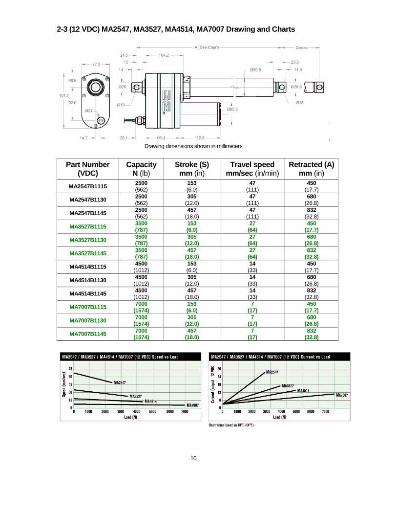
2-3 (12 VDC) MA2547, MA3527, MA4514, MA7007 Drawing and Charts
Drawing dimensions shown in millimeters
Part Number (VDC)
Capacity N (lb)
Stroke (S) mm (in)
Travel speed mm/sec (in/min)
Retracted (A) mm (in)
MA2547B1115 2500 (562)
153 (6.0)
47 (111)
450 (17.7)
MA2547B1130 2500 (562)
305 (12.0)
47 (111)
680 (26.8)
MA2547B1145 2500 (562)
457 (18.0)
47 (111)
832 (32.8)
MA3527B1115 3500 (787)
153 (6.0)
27 (64)
450 (17.7)
MA3527B1130 3500 (787)
305 (12.0)
27 (64)
680 (26.8)
MA3527B1145 3500 (787)
457 (18.0)
27 (64)
832 (32.8)
MA4514B1115 4500 (1012)
153 (6.0)
14 (33)
450 (17.7)
MA4514B1130 4500 (1012)
305 (12.0)
14 (33)
680 (26.8)
MA4514B1145 4500 (1012)
457 (18.0)
14 (33)
832 (32.8)
MA7007B1115 7000 (1574)
153 (6.0)
7 (17)
450 (17.7)
MA7007B1130 7000 (1574)
305 (12.0)
7 (17)
680 (26.8)
MA7007B1145 7000 (1574)
457 (18.0)
7 (17)
832 (32.8)

11
2-4 (120 VAC) MA1527 & MA3507 Drawing and Charts
Drawing dimensions shown in millimeters
Part Number (VAC)
Capacity N (lb)
Stroke mm (in)
Travel speed mm/sec (in/min)
Retracted (A) Mm (in)
MA1527B8115 1500 (337)
153 (6.0)
23 (54)
410 (16.1)
MA1527B8130 1500 (337)
305 (12.0)
23 (54)
613 (24.1)
MA1527B8145 1500 (337)
457 (18.0)
23 (54)
765 (30.1)
MA3507B8115 3500 (787)
153 (6.0)
6 (14)
410 (16.1)
MA3507B8130 3500 (787)
305 (12.0)
6 (14)
613 (24.1)
MA3507B8145 3500 (787)
457 (18.0)
6 (14)
765 (30.1)

12
2-6 (120 VAC) MA2547, MA3527, MA4514, MA7007 Drawin g and Charts
Drawing dimensions shown in millimeters
Part Number (VAC)
Capacity N (lb)
Stroke (S) mm (in)
Travel speed mm/sec (in/min)
Retracted (A) mm (in)
MA2547B8115 2500 (562)
153 (6.0)
47 (111)
450 (17.7)
MA2547B8130 2500 (562)
305 (12.0)
47 (111)
680 (26.8)
MA2547B8145 2500 (562)
457 (18.0)
47 (111)
832 (32.8)
MA3527B8115 3500 (787)
153 (6.0)
27 (64)
450 (17.7)
MA3527B8130 3500 (787)
305 (12.0)
27 (64)
680 (26.8)
MA3527B8145 3500 (787)
457 (18.0)
27 (64)
832 (32.8)
MA4514B8115 4500 (1012)
153 (6.0)
14 (33)
450 (17.7)
MA4514B8130 4500 (1012)
305 (12.0)
14 (33)
680 (26.8)
MA4514B8145 4500 (1012)
457 (18.0)
14 (33)
832 (32.8)
MA7007B8115 7000 (1574)
153 (6.0)
7 (17)
450 (17.7)
MA7007B8130 7000 (1574)
305 (12.0)
7 (17)
680 (26.8)
MA7007B8145 7000 (1574)
457 (18.0)
7 (17)
832 (32.8)

13
Section III Order information
3-1 Part Number Description
3-2 Serial Number The serial number is etched on the front of each actuator, just below the Joyce Logo. Use the serial number to positively identify the actuator when reordering or when communicating with Joyce/Dayton.
Joyce/Dayton Corporation P.O. Box 1630
Dayton, Ohio 45401 Phone (800) 523-5204 (U.S. & Canada); (937) 294-626 1 Fax (937) 297-7173
www.joycedayton.com E-mail: [email protected] FB0254 – 10/12

14

15

16
Manual available at www.joycedayton.com