Fault Wizard - Webs
44
Fault Wizard TM Owner's Manual Innovative Utility Products Corporation Made in the USA Model No. IUPFW1 Serial Number: ___________ Read This Manual Before Operation! Innovative Utility Products Corporation P. O. Box 1667, 2524 S. 25 th Circle, Van Buren, AR 72957 Phone: (479) 410-2098; FAX: (479) 410-3260
Transcript of Fault Wizard - Webs

Fault Wizard TM
Owner's Manual
Innovative Utility Products Corporation
Made in the USA
Model No. IUPFW1
Serial Number: ___________
Read This Manual Before Operation!
Innovative Utility Products CorporationP. O. Box 1667, 2524 S. 25th Circle, Van Buren, AR 72957
Phone: (479) 410-2098; FAX: (479) 410-3260

E-Mail: [email protected]; Web Page: www.iupcorp.com
© Copyright 1999 by Innovative Utility Products Corp. 2 Rev. 1.11b

Safety Rules and Issues
Warnings
Read the ENTIRE Owner’s Manual before operating! Updates to this manual canbe found at http://www.iupcorp.com/iupcorp/downloads.htm.
Failure to follow all instructions may result in electric shock, fire, serious injury or death. Save these instructions with the Fault Wizard for reference by all operators.
Follow all local, State, Federal (Country) laws and codes that govern working withHigh Voltage equipment such as the Fault Wizard. It is highly recommended that aformal Standard Operating Procedure (SOP) be established for the use of the FaultWizard in your specific environment following all government regulations and yourinternal company rules and regulations for such use.
Danger- HIGH VOLTAGE delivered at output connectors! The Fault Wizardproduces a high-voltage electrical discharge that is potentially LETHAL. Onlypersonnel trained in the safe handling and operation of high voltage electricaldevices should use this device. Do not allow persons unfamiliar with the FaultWizard to operate.
Wearing properly rated high-voltage electrical gloves is mandatory while operatingthis device!
Inspect output cables before use. DO NOT USE if damaged insulation is present.
DO NOT USE if the control panel or blue case is cracked or contains holes that willallow potentially combustible material inside the unit such as coal dust. Use of theunit under such conditions could lead to an EXPLOSIVE situation!!!
This device creates sparks. Therefore, for environments where explosive orcombustible gas is possible, gas checks should be performed before, during, andafter using the Fault Wizard.
To avoid the possibility of electrical shock, always remember to turn off the FaultWizard (Power toggle switch) before connecting or disconnecting the cables orhandling the clips.
High voltage output is from the Red clip. Keep all clips connected to a cable undertest, the cable cleats or to each other. High voltage can be present at the red clipand you should always maintain knowledge of all three clips positions and
© Copyright 1999 by Innovative Utility Products Corp. 3 Rev. 1.11b
connections. Clip boots are for identification purposes only and are NOT rated forhigh voltage. DO NOT AT ANY TIME attempt to handle the clips or boots whilethe Fault Wizard is ON.
Before closing the lid, turn the Power toggle switch to off, turn the Voltage knob tozero, and turn the Mode knob to HV TDR. Please clip all three clips to the cablecleats to insure the HV output (red clip) is shorted to HV return (black clip) andchassis ground (green clip).
Inform everybody in the area to avoid body contact with earthed or groundedsurfaces such as pipes, transformers, fences, cables, equipment (including the FaultWizard), etc. to avoid the possibility of electrical shock from step (ground return)currents. For the operator, wearing the mandatory high-voltage electrical gloveswhile operating the unit will also eliminates this risk. Keep children and bystandersaway while operating this device.
Do not expose the Fault Wizard to rain or wet conditions. Water entering orpooling on the unit increases the risk of electric shock or equipment damage.
The Fault Wizard contains high-energy capacitors, electrical shock is possible evenif the Fault Wizard is unplugged and off! Only qualified personnel should attemptto repair the Fault Wizard! If service is required, return the unit to the factoryonly. No field serviceable parts are inside the unit. Danger of electrical shock existsif removed from the case. See return information located elsewhere in this Owner’sManual.
To reduce the possibility of electrical shock, always make sure the Fault Wizard isunplugged and turned off while cleaning (see Maintenance Section).
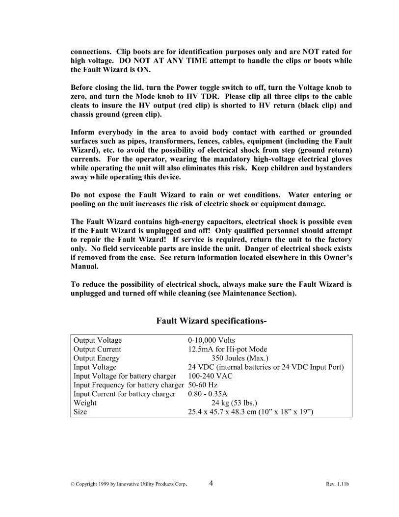
Fault Wizard specifications-
Output Voltage 0-10,000 VoltsOutput Current 12.5mA for Hi-pot ModeOutput Energy 350 Joules (Max.)Input Voltage 24 VDC (internal batteries or 24 VDC Input Port)Input Voltage for battery charger 100-240 VACInput Frequency for battery charger 50-60 HzInput Current for battery charger 0.80 - 0.35AWeight 24 kg (53 lbs.)Size 25.4 x 45.7 x 48.3 cm (10” x 18” x 19”)
© Copyright 1999 by Innovative Utility Products Corp. 4 Rev. 1.11b

Table of Contents
Sections Page #
• Safety Rules and Issues . . . . . . 2-3
• Introduction . . . . . . . 5
• Setup . . . . . . . 5
• Operation . . . . . . . 6
• Test Procedure . . . . . . . 13
• Helpful Facts . . . . . . . 16
• Maintenance . . . . . . . 17
• Repair . . . . . . . 17
• Warranty . . . . . . . 18
• Technical Support . . . . . . . 18
• Specifications . . . . . . . . 18
• Table 1. (Velocity of Propagation Values) . . . . 19
• Fault Wizard Software. . . . . . . 20
• Battery Pack . . . . . . . 26
• AC Pack . . . . . . . 29
© Copyright 1999 by Innovative Utility Products Corp. 5 Rev. 1.11b
Introduction
Congratulations on your purchase of the Fault Wizard primary cable fault locator. TheFault Wizard requires no user assembly and is ready for setup and operation. Some of thesignificant qualities of the Fault Wizard in comparison to all other Arc-Reflection(TDR/thumper) fault location systems are its relatively small size, low weight, and easeof operation. These qualities make it easy to hand carry to the needed location for quickand precise fault location. Due to the automated nature of the Fault Wizard, training forits operation is quick and easy.
The basic method behind any Arc-Reflection system is to produce an arc at the faultlocation of a de-energized cable and to bounce a TDR pulse off of the arc in order tocalculate how far down the cable the fault is located.
The Fault Wizard is designed to thump through multiple transformers on a de-energizedcircuit where a fault has occurred. You may thump from the open point, switchgear, oran overhead riser. Since the Fault Wizard will give you the distance to the fault location,you will be able to quickly identify and isolate the faulted cable between twotransformers, thus restoring service quickly. After the cable has been isolated, the Hi-PotMode can be used to test the isolated cable to confirm (before re-closure) that the cablecontains the fault. Even though the Fault Wizard is compact and lightweight it stilldelivers almost as large a pulse of energy as many thumpers associated with TDRsystems. The discharge delivered at the cable fault can be heard above ground withcommon listening devices used by the electrical utility industry and heard quite often withjust your own ears. This gives the Fault Wizard a stand-alone capability whenpinpointing the location of a fault after the faults general location has been determined.The Cycle Mode of operation allows repeated thumping (every six seconds at fullvoltage) for pinpointing the fault.
Setup
Initial Inspection
Each Fault Wizard has been inspected for its quality of construction and operation. If youhave any problems with your Fault Wizard, please refer to the Repair and Warrantysections in this manual.
Operating Conditions
Although the Fault Wizard is battery operated, it requires access to 100-240 VACelectrical power for battery recharging. Always place the Fault Wizard on a flat stablesurface. The Fault Wizard will operate properly over normally encountered temperatureranges. Restrain your Fault Wizard while it is in your vehicle to prevent it fromsliding into hard objects or being bounced around. The Fault Wizard is constructed tobe durable, although, excessively rough handling can damage it and voids the warranty.
© Copyright 1999 by Innovative Utility Products Corp. 6 Rev. 1.11b
Wet Environment
Although the Fault Wizard is designed to be internally shielded from the outsideenvironment, the Fault Wizard is not “water proof”. You should think of the FaultWizard as being “splash resistant”. Minimum exposure of the Fault Wizard to a wetenvironment is highly recommended. If your Fault Wizard is exposed to a wetenvironment, then dry the Fault Wizard completely with a towel as soon as possible. Thecables should be unwrapped from the lid and completely dried. DO NOT just shut the lidwith wet cables and panel because the water will pool on the panel and greatly increasethe chance of water entering into the unit. Failure of the unit because of water damagevoids the warranty!
Caution - Although the Fault Wizard is designed to be internally shielded from the outsideenvironment, to avoid the possibility of electrical shock, never expose the Fault Wizardto a wet environment.
Grounding Instructions
For most electrical products, grounding provides a path of least resistance to prevent thepossibility of electrical shock. The Fault Wizard is provided with a copper braid"grounding cord" attached to an alligator clip connector (green) at one end and the FaultWizard's internal metal frame at the other end. The alligator clip connector must beconnected to a solid and stable ground before the Fault Wizard is turned on. All localcodes and ordinances should be followed when grounding the Fault Wizard.
Caution - Improper grounding of the Fault Wizard can result in the risk of electrical shock andimproper operation of the instrument! Check with a qualified electrician if you are indoubt as to whether a power source or grounding object is properly grounded.
Operation
The Fault Wizard is operated from the panel of the instrument. There are two cables, twoknobs, six buttons, a toggle switch, three receptacles, and a LCD display on the FaultWizard. Each of these will be discussed in detail below.
Cables
The HV Output cable provides the output for both the high voltage and the TDR pulses.The ground cable is used to ground the internal frame of the Fault Wizard to an externalground. An alligator clip (green) is provided at the end of the ground cable. The groundcable must be clipped to a well-grounded object before connecting the HV Outputcable or before the Fault Wizard is turned on. Attached to the end of the HV Output
© Copyright 1999 by Innovative Utility Products Corp. 7 Rev. 1.11b

cable is two alligator clips with rubber boots over the clips. The clip with the red bootshould only be attached to the center conductor of the power cable under test. Theclip with the black boot should only be attached to the concentric neutrals of thepower cable under test. For ease of storage and use, the cables should be held togetherwhen wrapping them around the cable cleats inside the lid and all three clips should beclipped to the cleats.
Warning- To avoid the possibility of electrical shock, always remember to turn off the Fault Wizardbefore connecting or disconnecting the cables.
Power Switch
The Power toggle switch is used to turn on the main power to the instrument. Turningthe Power switch off returns the Fault Wizard to a safe mode. In order to conserve theenergy stored in the batteries, turn the Power switch off when the Fault Wizard is not inuse.
Knobs
The Voltage knob adjusts the HV power supply voltage (0-10 kV). The Mode knobselects the Fault Wizard's operating mode. There are three modes of operation: (1) HVTDR, (2) Cycle, and (3) Hi-Pot. It is safe practice to turn the Voltage knob to zeroafter you are finished using the instrument or before changing into Hi-Pot Mode.
HV TDR Mode
The Fault Wizard is used in HV TDR Mode to activate the automated Arc-Reflectionsystem in order to determine the distance to the fault. By pressing the HV Start button inHV TDR Mode, the HV capacitor in the Fault Wizard is charged to the value set by theVoltage adjust knob. Next, by pressing the Thump button, the energy stored in the HVcapacitor is discharged into the cable under test while the TDR system is simultaneouslyactivated. In addition, the Fault Wizard is returned to an unenergized state. Press theStop/Ground button at any time to stop the test and return the instrument to anunenergized state.
Cycle Mode
The Fault Wizard is used in Cycle mode (with listening equipment) to pinpoint a fault.By pressing the HV Start button in Cycle mode, the Fault Wizard starts to charge anddischarge in a cyclic fashion. The Voltage knob setting, with a maximum of 6 seconds atfull voltage, determines the cycle time. If the cable under test does not break down froma discharge at any time during cycle thumping, the cycle will stop. However, thecapacitor will still be at the set charge voltage. If this occurs, either increase the voltagesetting on the Voltage adjust knob until the cable breaks down and cycle thumpingresumes or press the Stop/Ground button. Press the Stop/Ground button at any time to
© Copyright 1999 by Innovative Utility Products Corp. 8 Rev. 1.11b

stop the cycle thumping and return the instrument to an unenergized state. The energy ofthe pulse delivered to the power cable is dependent on the charge voltage of the internalcapacitor when the Fault Wizard is discharged. Energy of 350 J is stored when thecapacitor is charged to 10 kV.
Hi-Pot Mode
The Fault Wizard is primarily used in Hi-Pot mode to confirm that an isolated section ofcable actually has the fault. By pressing the HV Start button in Hi-Pot mode, the DCoutput voltage will try to rise to the voltage set by the Voltage Adjust knob. Therefore,good practice is to set the Voltage Adjust knob to zero before pressing the Start button.The hold-off voltage of the cable can be determined by raising the DC output voltagegradually by use of the Voltage Adjust knob. The voltage displayed by the LCD meterwill not rise above the breakdown voltage of the cable. You will usually see a suddendrop in voltage on the meter when the cable breakdown voltage is reached. Whendesired, press the Stop/Ground button to stop the test and return the instrument to an un-energized state.
Buttons
HV Start
The green HV Start button turns on the HV power supply and illuminates the red LED onthe control panel. In HV TDR Mode or Cycle Mode, the capacitor is charged to thevoltage level set by the Voltage adjust knob. In Hi-Pot Mode, the DC output voltage triesto rise to the voltage set by the Voltage adjust knob. (Note: for newer models, a “ZeroStart” feature has been added. The Voltage knob must be set to zero before the HVStart button is enabled.)
Thump
In HV TDR Mode, the yellow Thump button fires the Fault Wizard (HV dischargecoupled with a TDR pulse). The Fault Wizard is then returned to an unenergized state.
Stop/Ground
The red Stop/Ground button turns off the HV power supply and internally grounds theHV capacitor through a dump resistor and internally grounds the output (red booted) lead.The red LED also ceases to illuminate. In addition, holding the Stop/Ground buttondown for three seconds changes the LCD Display to the following:
STORE WAVEFORM IN MEMORYCANCEL-GO TO MAIN SCREEN
Pressing the Stop/Ground button a second time chooses the selection made and returnsthe LCD Display to the Main screen.
© Copyright 1999 by Innovative Utility Products Corp. 9 Rev. 1.11b

Cable Vp (Up and Down)
The two Cable Vp buttons (Up and Down) are used to change the velocity of propagation(Vp) setting for the cable under test. In addition, the Up and Down buttons are used toscroll through the selections in the Store Waveform In Memory mode.
LV TDR
The green LV TDR button is used to fire a low-voltage TDR pulse down the cable(without a HV discharge) to determine the distance to an open (often used to determinethe full length of the cable under test). The LV TDR button is deactivated when the HVpower supply is on (red LED illuminated).
Data Port
The Data Port receptacle is used to download waveform data to a computer by utilizationof the Fault Wizard Software. The receptacle is a standard 9-pin D-Subminiatureconnector. A compatible communication cable is provided with the Fault Wizard.
Battery Charger
The Fault Wizard uses two 12 VDC, 8.5 AH rechargeable lead-acid batteries. On a fullcharge they should allow the Fault Wizard to be charged and discharged hundreds oftimes before recharging is required. The battery voltage is displayed on the meter. Whenthe voltage reads below 22 volts for more than 3 seconds, the battery voltage will flash onthe LCD Display. The batteries will need to be recharged soon. Charging isaccomplished using a standard equipment power cord (supplied) and a single-phase 100-240 VAC power outlet. While charging the batteries, the battery voltage on the LCDDisplay will slowly increase. The Fault Wizard does NOT need to be on to charge thebatteries. Fully recharging completely depleted batteries takes about 6 hours. Rechargingthe batteries for long periods of time does not hurt the batteries. In order to protect thebattery charger, the Fault Wizard should not be operated while charging thebatteries. A 24 VDC output auxiliary Battery Pack or 24 VDC output AC Pack can bepurchased to allow continued field use if the batteries run low or fail. Eventually, theinternal batteries, like all batteries, will fail and you will have to send your Fault Wizardback to our Repair Center for replacement of the batteries (see Maintenance section).(Note: for newer models, the Battery Charger is mounted inside the lid between thecable cleats. A cord with a connector at the end runs from the Battery Charger tothe input port on the panel. The AC input receptacle for the Battery Charger ismounted on the outside on top of the lid by the handle).
Lead Acid Batteries
As mentioned earlier, the Fault Wizard uses two internal sealed lead-acid batteries.Unlike Ni-Cad batteries, lead-acid batteries DO NOT like to be deep discharged. Deepdischarging the batteries will decrease the energy storage capacity and life of the batteries.To avoid deep discharging the batteries, do not continue to operate the Fault Wizard after
© Copyright 1999 by Innovative Utility Products Corp. 10 Rev. 1.11b

the battery voltage begins flashing on the LCD Display. At this point, the batteries needto be recharged or an external 24 VDC source (Battery or AC Pack) needs to be utilized.Innovative Utility Products Corp. highly recommends purchasing one of the auxiliarypacks if the Fault Wizard is going to be used for cycle thumping. In addition, if the FaultWizard power is left on for an extended period of time and the batteries completelydischarge, the batteries will die and quite often cannot be recharged. If the batteries aredead, plugging in the Fault Wizard to recharge the batteries will not accomplishrecharging the batteries. For this situation, the battery voltage on the LCD Display willshow about 28 volts because the batteries have “opened up” and are not drawing current,therefore, not pulling the charger voltage down. By the way, batteries are not coveredby the warranty! Remember to turn off the power to your Fault Wizard when youare finished to avoid killing your batteries!
24 VDC Input
The Aux. 24 VDC Input receptacle is used to provide 24 DC auxiliary power to the FaultWizard. A compatible power cord is provided with the purchase of the auxiliary BatteryPack or AC Pack.
LCD Display
On power up, the LCD Display shows the following:
STARTUP DIAGNOSTIC TESTRESULT: PASS
The result should be PASS. If the result is FAIL, a message stating to contact the factoryis shown. The LCD Display then momentarily shows the following:
TDR Version 8.4.2
or what ever version number your Fault Wizard contains at present time. The LCDDisplay then shows momentarily the following:
NORMAL CABLEIMPEDANCE SELECTED
or possibly LOW instead of NORMAL, depending on the last setting used. Thedifference in the two settings will be discussed at the end of this section. Display thenshows momentarily the following:
15FTCL
or possibly 40FTCL, depending on whether your Fault Wizard has long cable leads orshort cable leads. Finally, the LCD Display shows the Main Screen, which looks similarto the following:
© Copyright 1999 by Innovative Utility Products Corp. 11 Rev. 1.11b

CV:00.0KV BV:24.2VRD:?????F RT:?? VP.513
where CV, BV, RD, RT, and VP indicate the HV power supply’s charge voltage, batteryvoltage, reflection distance, reflection type, and velocity of propagation setting,respectively.
For typical Arc-Reflection scenarios (HV TDR), the reflection distance (RD) displayedshould be the distance to the fault (arc) and the reflection type (RT) should show SH forshort (since an arc looks like a short to the TDR system). For resistive arc conditions (notflashing from center to outer conductor), RT will show a blinking RF indicating aresistive fault and RD will give the distance to the open point when operating in NormalCable Impedance mode. Under Low Cable Impedance mode, HV TDR always tries toyield the distance to the arc or short. If the condition is a pre-short or resistive, then RTwill show a blinking SH. LV TDR always looks for an open point and RT always showsOP. The velocity of propagation (VP) is the fraction of the speed of light the signaltravels up and down the cable. Typical values for power cables will range between .4 and.6. Refer to the list of Vp values for various cable types found in Table 1 later in thisManual.
Calibration of the Vp for any specific cable type can easily be accomplished by use of theLV TDR function on a length (spool) of cable if the length of cable is known. Hook upthe HV Output cable as described above in the Cables section. Next, turn on the Powerswitch to the Fault Wizard. Now, press the LV TDR button. As you can see on the LCDDisplay, you should get a value for the reflection distance (RD). Next, press the Up orDown button for the Cable Vp until the reflection distance shows the value of the lengthof cable under test. The value of the velocity of propagation setting (VP) is the Vp valuefor that type of cable. You should note that no high voltage was ever applied to the cableunder test.
Waveform Storage
Holding down the Stop/Ground button for three seconds changes the LCD Display to thefollowing: We will refer to this screen as the beginning screen.
STORE WAVEFORM IN MEMORYCANCEL-GO TO MAIN SCREEN
Pressing the Up button changes the display to read the following:
MEMORY NUMBERS 01 TO 08
Pressing the up button again changes the display above to the same but with 09 to 16.Since eight waveforms are stored each time the TDR system is activated (Thump or LVTDR), you can select between 01 to 08, 09 to 16, …, and 105 to 112. Therefore, you canstore fourteen activations (eight waveforms per activation) of the TDR system.
© Copyright 1999 by Innovative Utility Products Corp. 12 Rev. 1.11b
You can also press the Down button to move backwards. For example, in order to get tothe CLEAR ALL MEMORY NUMBERS screen from the beginning screen, just push theDown button once. The LCD Display will show the following:
CLEAR ALL MEMORY NUMBERS
Pressing the down button one more time changes the display to read the following:
SWITCH TO LOWCABLE IMPEDANCE
Pressing the down button one more time changes the display to read the following:
SWITCH UNITS TO METERS
Pressing the down button one more time changes the display to read the following:
MEMORY NUMBERS 105 TO 112
In order to select any screen and go back to the Main Screen, press the Stop/Groundbutton once. In order to NOT select anything and go back to the Main Screen,make sure you are on the following screen and press the Stop/Ground button.
STORE WAVEFORM IN MEMORYCANCEL-GO TO MAIN SCREEN
Assuming that you chose to store the next group of waveforms in the first eight memoryslots, the Main screen will look something like the following:
CV:00.0KV BV:24.2V M01RD:?????F RT:?? VP.513
As you can see, the M01 was added to the screen to indicate that the Fault Wizard isarmed for waveform storage in the first four non-volatile memory slots. As soon as theTDR system is activated, the M01 will disappear. Non-volatile memory means that thewaveforms will not be erased if you turn off the Fault Wizard. The only way to erase thememory slots is to choose the CLEAR ALL MEMORY NUMBERS selection.Therefore, selection of any one of the fourteen memory groups (eight waveforms pergroup) will display one of the following: M01, M09, …, or M105.
Most of the time, you will want to operate the Fault Wizard under the NORMAL CABLEIMPEDANCE mode. However, for some cable types such as “mining cable” and “feedercable” (such as 750 or 1000 MCM), the LOW CABLE IMPEDANCE mode will workbetter. Low impedance cable attenuates the waveforms to the point that this special modeof operation is sometimes necessary.
© Copyright 1999 by Innovative Utility Products Corp. 13 Rev. 1.11b

Test Procedure
Faulted Cable Section Isolation
1. Open the top of the Fault Wizard case in order to gain access to the control panel.
2. Ground the Fault Wizard as described in the Setup section in this manual.
3. Connect the Fault Wizard to the de-energized cable as shown in Figure 1. The redalligator clip attaches to the center conductor and the black clip to the concentricneutrals. The case ground should be connected to the system neutral. Note: Thecable you are connecting the Fault Wizard to should be tested for voltage to insurethe cable is de-energized.
Warning - High voltage output is from the Red clip. Keep all clips connected to a cable undertest, the cable cleats or to each other. High voltage can be present at the red clipand you should always maintain knowledge of all three clips positions andconnections.
Figure 1
4. Turn on the power to the Fault Wizard.
5. If the battery voltage is low (<22 volts) an auxiliary pack can be used. The FaultWizard batteries should be charged as soon as possible.
© Copyright 1999 by Innovative Utility Products Corp. 14 Rev. 1.11b
HV Cable
Grounding Cord
System Ground Bus
Green
Insulation
Red
Black
Center Conductor
Semicon
ConcentricNeutrals

6. Set the Mode knob to HV TDR.
7 Turn the Voltage knob to “Zero”
8. Press the HV Start button.
9. Set the Voltage knob to at least 7 kV. Although a good starting voltage for thecharge voltage, you may require higher voltage settings to get consistent readings.
10. Press the Thump button on the Fault Wizard to discharge the Fault Wizard into thetest cable. Note: The sound you here inside the Fault Wizard when you press thethump button can tell you important information about the system under test. Referto the “Helpful Facts” section for more information.
11. Wait for the Fault Wizard to display the distance to the fault.
12. Repeat steps 7 through 11 to see the consistency in the results. You may want toadjust the Fault Wizard's discharge voltage to obtain consistent Fault Wizardreadings. The more consistent the readings are, the more confident you will be onthe accuracy of the distance to the fault.
13. Based on the fault distance reading from the Fault Wizard, isolate the section ofcable that contains the fault. You may want to confirm that the isolated section ofcable is actually faulted by use of the Fault Wizard's Hi-Pot mode. This is describedin steps 14 through 22. Note: You can only use the Hi-Pot mode on isolated sectionsof cable not connected to any transformers.
Verifying Isolated Cable Section Is Faulted
14. Connect the Fault Wizard to the isolated cable to test.
15. Turn on the power to the Fault Wizard.
16. Turn the Voltage knob to zero.
17. Set the Mode knob to Hi-Pot mode.
18. Press the Start button.
19. Turn the Voltage knob to raise the voltage on the cable.
20. Note the hold-off voltage of the cable.
21. Press the Stop/Ground button to stop the test.
© Copyright 1999 by Innovative Utility Products Corp. 15 Rev. 1.11b

22. If the cable held-off the full 10 kV of voltage, then you probably have isolated an un-faulted section of cable. Therefore, isolate and hi-pot the closest sections of cable todetermine which one contains the fault.
Fault Pinpointing on Isolated Cable Section
1. Follow steps 1 through 5 above.
2. Turn the Voltage Adjust knob to zero.
3. Set the Mode knob to Hi-Pot mode. Note: you can only use the Hi-Pot mode onisolated sections of cable not connected to any transformers.
4. Press the HV Start button.
5. Turn the Voltage knob to raise the voltage on the cable.
6. Note the hold-off voltage of the cable.
7. Press the Stop/Ground button to stop the test.
8. Set the Mode knob to HV TDR.
9. Turn the Voltage knob to “Zero”
10. Press the Start button.
11. Set the Voltage knob to at least 7 kV. Although a good starting voltage for thecharge voltage, you may require higher voltage settings to get consistent readings.
12. Press the Thump button on the Fault Wizard to discharge the Fault Wizard into thetest cable. Note: The sound you here inside the Fault Wizard when you press thethump button can tell you important information about the system under test. Referto the “Helpful Facts” section for more information.
13. Wait for the Fault Wizard to display the distance to the fault.
14. Repeat steps 9 through 13 to see the consistency in the results. You may want toadjust the Fault Wizard's charge voltage to obtain consistent Fault Wizard readings.The more consistent the readings are, the more confident you will be on the accuracyof the distance to the fault.
15. Set the Fault Wizard mode to Cycle mode.
16. Turn the Voltage knob to “Zero”
17. Press the Start button.
© Copyright 1999 by Innovative Utility Products Corp. 16 Rev. 1.11b

18. Set the Voltage knob to at least 7 kV (note: loudest sound at the fault is produced at10 kV)
19. While the Fault Wizard is cycle thumping, go to the general location of the fault bymeasuring off the distance determined by the Fault Wizard to the fault.
20. By using proper listening equipment, you should be able to pinpoint the faultlocation.
Helpful Facts
This section has been included to help you better utilize your Fault Wizard locatingsystem.
1. The Fault Wizard must produce an arc at the fault from the center conductor to theconcentric neutrals before it can obtain the distance to the arc (fault). However,some cable failures may involve arcing to earth and/or semicon. Like all arc-reflection systems, the Fault Wizard can’t "lock in" on the distance to the fault forthese situations. Increasing the charge (discharge) voltage may help produce an arcfrom the center conductor to the concentric neutrals.
2. Listening to the internal thump sound the Fault Wizard makes in HV TDR mode isvery important. If there is a fault and the cable arcs from the center conductor to theneutrals (metal to metal) when the thump button is pressed, you should hear a solid“whack” sound from the Fault Wizard, itself. We refer to this situation as “hittinghard”. This is because the energy is quickly rushing out of the unit. If there is not afault or a resistive fault (arc to semi-con or dirt or gaps in the neutrals fromcorrosion), you will not hear the “whack” sound but a “dull” sound or just a clickingsound of the internal relay. We refer to this situation as “hitting soft”. Note: unlessyou hear the “whack” sound in HV TDR (hitting hard), you will not get the correctdistance reading.
3. Some cable failures may involve open-fault scenarios such as pull-apart splices orthe center conductor burning apart. Under these circumstances, using the lowvoltage TDR feature of the Fault Wizard will give the distance to the fault.Thumping the cable under HV TDR mode will confirm the fault distance for thesituation of the center conductor having burned apart.
4. If the fault is within 20 to 30 feet of the Fault Wizard, it is difficult for the FaultWizard to see the fault distance. This is true for all arc-reflection systems. On thedisplay (RD), you should get all question marks. However, on rare occasion, youmight get a false distance out a few hundred feet. If this occurs, then test from theother end.
© Copyright 1999 by Innovative Utility Products Corp. 17 Rev. 1.11b

Maintenance
The internal lead-acid batteries will eventually have to be replaced. Therefore, you willeventually have to send your Fault Wizard back to our Repair Center for replacement ofthe batteries. If you want to replace the internal batteries yourself, please call InnovativeUtility Products Corp. for guidance (see Repair section).
Calibration
Your Fault Wizard was calibrated during the manufacturing process. It can be sent backto our Repair Center for calibration (see Repair section).
Cleaning
The Fault Wizard can be cleaned externally with a damp (not wet) rag containing a mildsolution of soap and water or a typical household glass cleaner.
Do not use harsh cleaning solutions, such as organic solvents (e.g., acetone), that maymar the surfaces. Like most electrical items, do not immerse the Fault Wizard in any typeof liquid.
Warning- In order to avoid the possibility of electrical shock, always make sure the Fault Wizard isunplugged and turned off while cleaning it!
Warning -NEVER operate or turn on the Fault Wizard without the Red clip connected to a cableunder test or the cable cleats. High voltage can be present when unit is on and Class I orbetter High Voltage rated gloves must be worn whenever handling the Red clip.
Repair
Your Fault Wizard can be sent back to our Repair Center for repair. Before sending itback, please call our Repair Center at (479) 410-2098 for shipping instructions. If youdecide to repair or modify your Fault Wizard by any other means than shipping it to ourRepair Center, Innovative Utility Products Corp. assumes no liability for injury (or death)resulting from your Fault Wizard. In addition, any attempt to repair or modify your FaultWizard (without IUP approval) voids the warranty.
Warning- Since the Fault Wizard contains high-voltage capacitors, electrical shock is possible evenif the Fault Wizard is unplugged! Only qualified personnel should attempt to repair theFault Wizard.
© Copyright 1999 by Innovative Utility Products Corp. 18 Rev. 1.11b

Warranty
Innovative Utility Products Corporation (IUP) warrants its products to be free fromdefects in material and workmanship under normal and proper use for a period of oneyear from date of shipment from IUP's factory. Any products purchased from IUP thatupon inspection at IUP's factory prove to be defective will be repaired (at IUP's option)without charge. This limited warranty shall be void in regard to (1) any product or partwithout IUP's previous written consent or (2) any product or part thereof that has beensubjected to unusual electrical, physical or mechanical stress or upon which the originalidentification marks have been removed or altered. Transportation charges for shippingany product or part thereof that the buyer claims is covered by this limited warranty shallbe paid by the buyer. With the express warranty set out above, IUP does not grant anywarranties either expressed or implied, including implied warranties of merchantability orfitness for use.
The obligations or liabilities of IUP specifically shall not be liable for damages, IUPspecifically shall not be liable for reinstalling any product or part thereof repaired orreplaced under the limited warranty set out above. IUP expressly excludes all liability forany indirect or consequential damages the buyer may sustain in connection with thedelivery, use, or performance of IUP's products. Under no circumstances shall any liability for which IUP is held responsible exceed theselling price to the buyer of IUP's products that are proven to be defective. This limitedwarranty applies exclusively to IUP's manufactured products. Any legal action for breachof any IUP warranty must be commenced within one year of the date on which the breachis or should have been discovered.
Technical Support
Innovative Utility Products Corporation believes in providing technical support in orderfor you to best utilize the Fault Wizard. In order to serve the needs of our customers wewelcome all comments and suggestions regarding the Fault Wizard. Technical Supportcan be reached at (479) 410-2098. Technical Support's Fax number is (479) 410-3260.
Specifications
Max Charge Voltage: 10 kVMax Hi-Pot Voltage: 10 kVMax Energy Storage: 350 JoulesMax Cycle Time: 6 seconds for 10 kV chargeWeight: 24 kg (53 lbs.)Size: 25.4 cm x 45.7 cm x 48.3 cm (10" x 18" x 19")Battery Capacity: 8.5 AH at 24 VBattery Charger Input Voltage: 100-240 VAC, 50/60 Hz, single phase
© Copyright 1999 by Innovative Utility Products Corp. 19 Rev. 1.11b

Table 1
Typical velocity of propagation values that can be used if needed. Values may varydepending on the number of transformers and splices in the circuit. If you are not sure,then try using a velocity of propagation that is about .520.
KV Class Mils Cable Size Type Vp
15 175 #1CU XLPE .55415 175 #2AL XLPE .49515 175 #2CU XLPE .51415 175 #4CU XLPE .51615 175 1/0 XLPE .52215 175 1/0 TRXLPE .51015 175 2/0 XLPE .48615 175 4/0 XLPE .47215 175 500MCM XLPE .52615 175 750MCM XLPE .53615 175 1000MCM TRXLPE .43015 175 #2AL EPR .54415 175 1/0 EPR .50815 175 4/0 EPR .57215 220 1/0AL TRXLPE .55025 260 1/0AL TRXLPE .54025 260 1/0AL (CU Ribbon) TRXLPE .57035 345 1/0 XLPE .565-- --- 2/0 Mining Trailing --- .430-- --- 4/0 MPF --- .540-- --- 2/0 MPF --- .520-- --- 2/0 GGC Round --- .500-- --- #2 GGC Round --- .540-- --- #4 -4/c W Round --- .530-- --- Pilot Wireless Avg. --- .600
© Copyright 1999 by Innovative Utility Products Corp. 20 Rev. 1.11b
Fault Wizard Software
Using the Fault Wizard Software
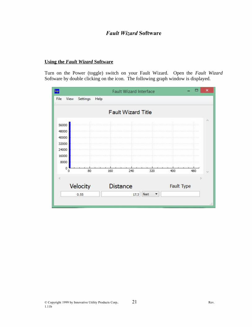
Turn on the Power (toggle) switch on your Fault Wizard. Open the Fault WizardSoftware by double clicking on the icon. The following graph window is displayed.
© Copyright 1999 by Innovative Utility Products Corp. 21 Rev. 1.11b

Next, choose Refresh Comm Ports submenu under the Settings menu. Then choose theCommunications Port option under the Settings menu and a side menu will appear.Choose the computer port that you want to use.
The most common problem encountered during the attempt to download waveforms fromthe Fault Wizard is communication between your computer and the Fault Wizard. If sucha problem occurs, make sure that you have selected the proper port. In addition, if someother application on your computer has been using that port, then that application may nothave released it for use by the Fault Wizard Software. A remedy of the problem is toopen that application and have that application choose a different port. You may (notalways) have to reboot your computer for the port selection to take effect.
Choose Retrieve Waveform from FW submenu under the File menu.
© Copyright 1999 by Innovative Utility Products Corp. 22 Rev. 1.11b

The following dialog box will appear.
© Copyright 1999 by Innovative Utility Products Corp. 23 Rev. 1.11b

Eight waveforms are stored in the Fault Wizard’s volatile or non-volatile memory eachtime the HV TDR system is activated (four waveforms are stored for LV TDR with theremaining four left blank). Volatile Memory holds the last HVTDR or LVTDR activationwhile the unit is on. Once the unit has been switched off the data in Volatile Memory isno longer valid. Non-Volatile Memory holds waveform data that has been saved tospecific memory locations and is retained through power cycles.
By the way, the Fault Wizard must be on in order for your computer to communicate withthe Fault Wizard. To retrieve LVTDR data from Volatile Memory select Volatile Memory in the Select Memory Type drop down list. Next select a Register, for Volatile Memory there are only 8 registers (or memory locations). Then you can select the consecutive number of waveforms to retrieve at once. Retrieval of LVTDR waveforms settings shown below.
© Copyright 1999 by Innovative Utility Products Corp. 24 Rev. 1.11b

Since the LVTDR waveform data consists of only 4 valid waveforms it is only necessaryto retrieve the first 4 registers as registers 5-8 will have only invalid noise. After enteringappropriate numbers in the entry boxes, the graph window will be updated to look likesomething shown below.
© Copyright 1999 by Innovative Utility Products Corp. 25 Rev. 1.11b

To retrieve HVTDR data from Volatile Memory select Volatile Memory in the Select Memory Type drop down list. Next select a Register. Then you can select the consecutivenumber of waveforms to retrieve at once. Retrieval of HVTDR waveforms settings shown below.
After entering appropriate numbers in the entry boxes, the graph window will be updatedto look like something shown below.
© Copyright 1999 by Innovative Utility Products Corp. 26 Rev. 1.11b
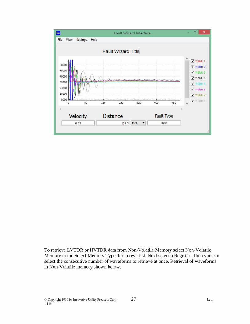
To retrieve LVTDR or HVTDR data from Non-Volatile Memory select Non-Volatile Memory in the Select Memory Type drop down list. Next select a Register. Then you can select the consecutive number of waveforms to retrieve at once. Retrieval of waveforms in Non-Volatile memory shown below.
© Copyright 1999 by Innovative Utility Products Corp. 27 Rev. 1.11b

Non-Volatile (saved) waveform data starts at register 1 and goes to 112. You can seefrom the example above that we are pulling data from the Fault Wizard starting at register9 and pulling in 8 registers. This would correspond with the second TDR activation savedin Fault Wizard memory.
Memory locations in Non-volatile memory for the first TDR activation saved.
Memory locations in Non-volatile memory for the second TDR activation saved.
Memory locations in Non-volatile memory for the 14th TDR activation saved.
© Copyright 1999 by Innovative Utility Products Corp. 28 Rev. 1.11b
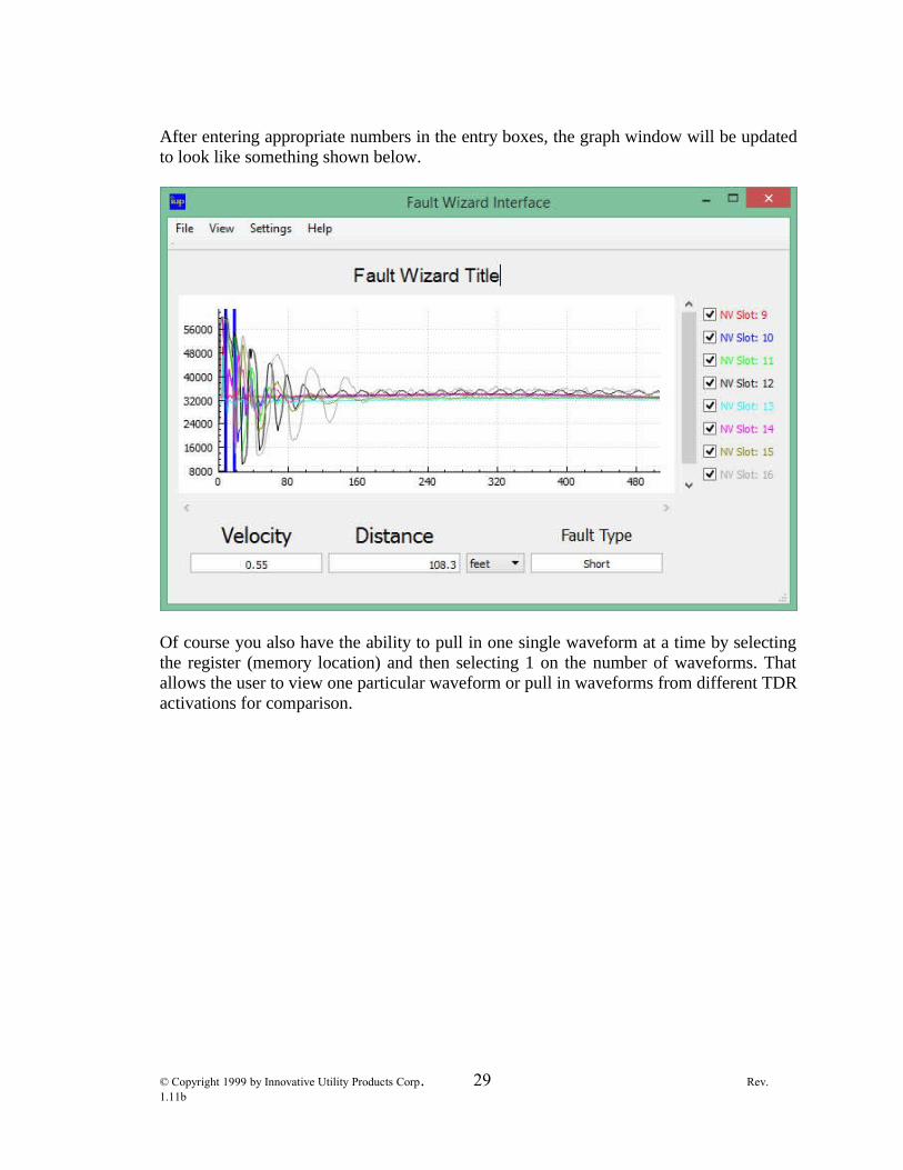
After entering appropriate numbers in the entry boxes, the graph window will be updatedto look like something shown below.
Of course you also have the ability to pull in one single waveform at a time by selectingthe register (memory location) and then selecting 1 on the number of waveforms. Thatallows the user to view one particular waveform or pull in waveforms from different TDRactivations for comparison.
© Copyright 1999 by Innovative Utility Products Corp. 29 Rev. 1.11b

As you can see, a red waveform is shown in the graph. You should also note that twovertical blue lines (cursors) appear in the graph and the values for the Distance BetweenCursors and Velocity of Propagation shown at the bottom of the graph have changed.The Velocity of Propagation (Vp) is stored in the waveform data and is displayed for thefirst waveform loaded into the graph. The position of the alligator clips is represented bythe left cursor. The position of the open point (for LV TDR) or the arc (for HV TDR) isrepresented by the right cursor. The distance between these two cursor lines based on thegiven Vp is displayed for the first waveform loaded into the graph. Loading additionalwaveforms into the graph does not change the position of the cursors or the Vp.
Change Cursor PositionYou can change the position of the cursors by clicking on the graph with the left mousebutton (for left cursor) or the right mouse button (for right cursor). Changing the cursorpositions does change the distance displayed.
Hide/Show WaveformsWhen there are waveforms displayed on the graph there is a legend displayed on theright-hand side. To hide waveforms shown in the graph, uncheck the appropriate “slot”on the right-hand side legend. To show it again, check it. The following example shows agraph with some of the waveforms hidden. Notice the check boxes on the right hand side.
© Copyright 1999 by Innovative Utility Products Corp. 30 Rev. 1.11b
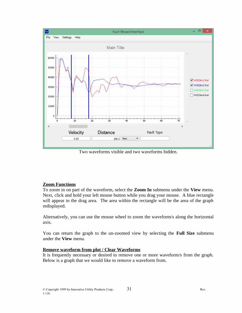
Two waveforms visible and two waveforms hidden.
Zoom FunctionsTo zoom in on part of the waveform, select the Zoom In submenu under the View menu.Next, click and hold your left mouse button while you drag your mouse. A blue rectanglewill appear in the drag area. The area within the rectangle will be the area of the graphredisplayed.
Alternatively, you can use the mouse wheel to zoom the waveform/s along the horizontalaxis.
You can return the graph to the un-zoomed view by selecting the Full Size submenuunder the View menu.
Remove waveform from plot / Clear WaveformsIt is frequently necessary or desired to remove one or more waveform/s from the graph.Below is a graph that we would like to remove a waveform from.
© Copyright 1999 by Innovative Utility Products Corp. 31 Rev. 1.11b

We want to remove the second (blue) waveform from the graph above so, first we'll needto left-click on the waveform to highlight it. Shown below is the highlighted bluewaveform.
© Copyright 1999 by Innovative Utility Products Corp. 32 Rev. 1.11b

With the blue waveform selected next right-click the waveform and you should see theoptions pictured below.
Simply locate and click the Remove from Plot option and the highlighted waveform isremoved from the graph along with the corresponding check box in the right hand legend(pictured below).
© Copyright 1999 by Innovative Utility Products Corp. 33 Rev. 1.11b

We will now retrieve the previously removed waveform again.
© Copyright 1999 by Innovative Utility Products Corp. 34 Rev. 1.11b
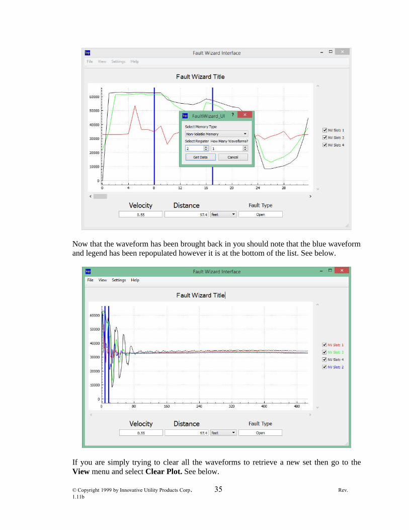
Now that the waveform has been brought back in you should note that the blue waveformand legend has been repopulated however it is at the bottom of the list. See below.
If you are simply trying to clear all the waveforms to retrieve a new set then go to theView menu and select Clear Plot. See below.
© Copyright 1999 by Innovative Utility Products Corp. 35 Rev. 1.11b

Below is the graph from above after the plot has been cleared.
Save Waveform to File
© Copyright 1999 by Innovative Utility Products Corp. 36 Rev. 1.11b

You can save a single loaded waveform to a file by clicking on the waveform in the graphhighlighting it and selecting the Save Waveform to Data File submenu under the Filemenu or right-clicking the waveform and selecting Save Waveform to Data File in theright-click options. The data is saved as a file with the Fault Wizard Data file extension(.fwd). You can reload any saved file by selecting the Open Waveform from Data Filesub menu under the File menu.
Save all WaveformsAlternately, the user has the ability to save all waveforms in the graph all at the sametime. To do this first give the graph a new Title by clicking the title above the graph thatsays “Fault Wizard Title”, or it may also say “Main Title”, and simply typing in a newtitle. It is suggested to use a title that is descriptive. In the example we have changed thetitle to “Phase A trans 4_5”.
© Copyright 1999 by Innovative Utility Products Corp. 37 Rev. 1.11b

After giving your graph a new title you then select Save All Waveforms. A save filedialog will ask for a location to save to. Then when you click OK all of the waveforms onthe graph will be saved with the graph title and number (1-8). Shown in the next exampleis the saved files from above with the filenames generated by the graph title.
© Copyright 1999 by Innovative Utility Products Corp. 38 Rev. 1.11b
You can also print the displayed graph by selecting the Print submenu under the Filemenu.
ExitTo quit the program, select the Exit submenu under the File menu or click the close boxlocated in the top right corner of the graph window.
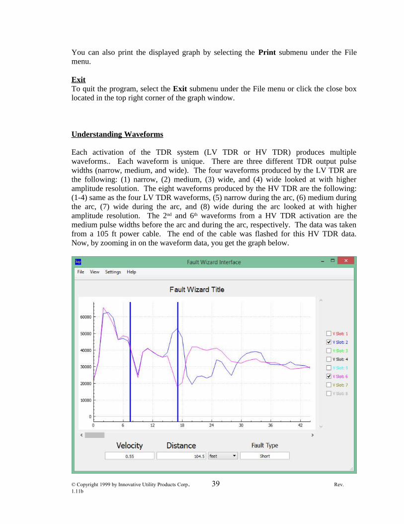
Understanding Waveforms
Each activation of the TDR system (LV TDR or HV TDR) produces multiplewaveforms.. Each waveform is unique. There are three different TDR output pulsewidths (narrow, medium, and wide). The four waveforms produced by the LV TDR arethe following: (1) narrow, (2) medium, (3) wide, and (4) wide looked at with higheramplitude resolution. The eight waveforms produced by the HV TDR are the following:(1-4) same as the four LV TDR waveforms, (5) narrow during the arc, (6) medium duringthe arc, (7) wide during the arc, and (8) wide during the arc looked at with higheramplitude resolution. The 2nd and 6th waveforms from a HV TDR activation are themedium pulse widths before the arc and during the arc, respectively. The data was takenfrom a 105 ft power cable. The end of the cable was flashed for this HV TDR data.Now, by zooming in on the waveform data, you get the graph below.
© Copyright 1999 by Innovative Utility Products Corp. 39 Rev. 1.11b
As you can see in the graph, there is a large positive output pulse followed by the “up &down” reflection of the alligator clips (both blue and purple waveforms). The left bluecursor is positioned in the center of the alligator clip reflection. Next, you see a positivereflection (blue waveform) from the open point at the end of the cable and a negativereflection (purple waveform) from the arc at the end of the cable. The right blue cursor ispositioned at the end of the cable. The remaining part of the graph shows “oscillations”from the reflections. If the cable had actually been flashed in the middle of the cableinstead of at the end, the negative reflection from the arc would have been closer to thealligator clip reflection than the open point reflection.
Battery Pack
An auxiliary Battery Pack can be purchased for use with the Fault Wizard. The BatteryPack is highly recommended for several reasons. The Battery Pack is a great “backup” incase the Fault Wizard’s internal batteries become depleted of energy or if the batteriesfail. Also, lead-acid batteries DO NOT like to be deep discharged. When the FaultWizard’s internal batteries become depleted, the battery voltage (BV) on the display willblink. Although continued operation can be performed, the result is deep discharging ofthe internal batteries. This can decrease the life and energy storage capacity of theinternal batteries. The Battery Pack gives the user an alternative to continuing the use ofthe internal batteries after the battery voltage (BV) on the display begins to blink. TheBattery Pack consists of the following components: (1) grey polycarbonate Battery Boxwith chrome handle and black connector port, (2) black Battery Charger with 115 VACequipment cord, and (3) grey Hookup Cord with black connector at each end.
© Copyright 1999 by Innovative Utility Products Corp. 40 Rev. 1.11b
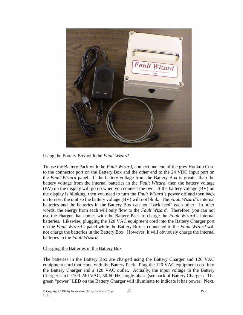
Using the Battery Box with the Fault Wizard
To use the Battery Pack with the Fault Wizard, connect one end of the grey Hookup Cordto the connector port on the Battery Box and the other end to the 24 VDC Input port onthe Fault Wizard panel. If the battery voltage from the Battery Box is greater than thebattery voltage from the internal batteries in the Fault Wizard, then the battery voltage(BV) on the display will go up when you connect the two. If the battery voltage (BV) onthe display is blinking, then you need to turn the Fault Wizard’s power off and then backon to reset the unit so the battery voltage (BV) will not blink. The Fault Wizard’s internalbatteries and the batteries in the Battery Box can not “back feed” each other. In otherwords, the energy from each will only flow to the Fault Wizard. Therefore, you can notuse the charger that comes with the Battery Pack to charge the Fault Wizard’s internalbatteries. Likewise, plugging the 120 VAC equipment cord into the Battery Charger porton the Fault Wizard’s panel while the Battery Box is connected to the Fault Wizard willnot charge the batteries in the Battery Box. However, it will obviously charge the internalbatteries in the Fault Wizard.
Charging the Batteries in the Battery Box
The batteries in the Battery Box are charged using the Battery Charger and 120 VACequipment cord that came with the Battery Pack. Plug the 120 VAC equipment cord intothe Battery Charger and a 120 VAC outlet. Actually, the input voltage to the BatteryCharger can be 100-240 VAC, 50-60 Hz, single-phase (see back of Battery Charger). Thegreen “power” LED on the Battery Charger will illuminate to indicate it has power. Next,
© Copyright 1999 by Innovative Utility Products Corp. 41 Rev. 1.11b

plug the connector from the Battery Charger to the connector port on the Battery Box.The yellow “charge” LED on the Battery Charger will illuminate to indicate that chargingof the batteries is occurring. When the batteries are fully charged, the charger goes into“trickle mode” and the yellow LED turns off indicating that your batteries are fullycharged. It does not hurt the batteries to leave them hooked up to the Battery Chargerafter the batteries are fully charged. It takes about 6 hours to fully charge depletedbatteries. If the yellow “charge” LED on the Battery Charger does NOT turn offafter about 8 hours of charging your Battery Box, then please disconnect thecharger from the Battery Box and replace your batteries. There is a possibility ofan internal short in one of the batteries and overheating of the Battery Box andBattery Charger can occur. The Battery Charger does not have enough power to powerthe Fault Wizard. DO NOT connect the Battery Charger to the 24 VDC Input porton the Fault Wizard’s panel or damage to both devices may occur and voids thewarranty.
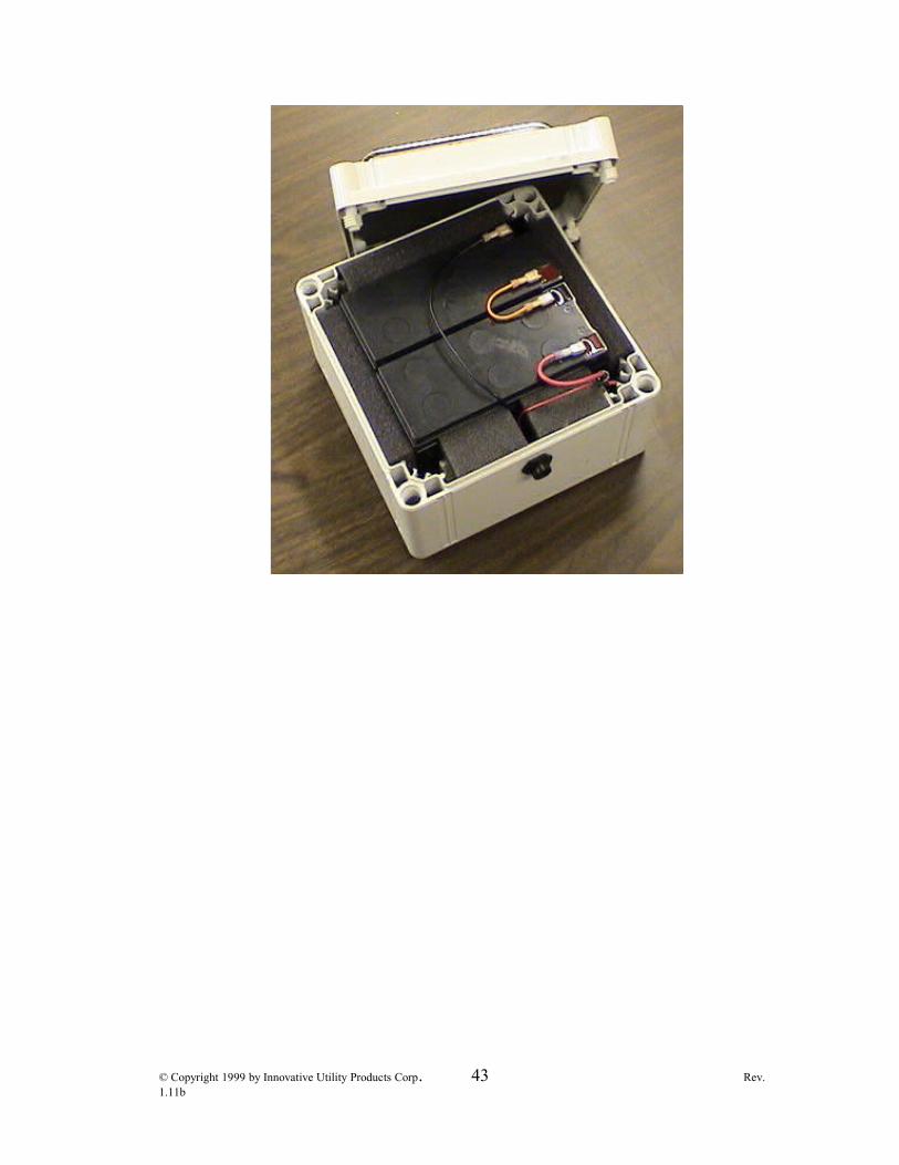
Replacing the Batteries in the Battery Box
It is quite easy to replace the batteries in your Battery Box. Unscrew the four plastic boltsfrom the four top corners of the Battery Box lid with a large flathead screwdriver. Thefour plastic bolts remain in the lid. Lift the lid off of the Battery Box. The picture belowshows the inside of the Battery Box.
Next, remove the four “quick connect” connectors from the batteries’ terminals by pullingon the connectors (not the wires!). The use of needle-nose pliers makes removing andattaching the connectors quite easy. You can now remove and replace the batteries.After you are finished replacing the batteries, reconnect the connectors to the terminals.Place the lid back onto the Battery Box and tighten the four plastic screws at the fourcorners of the lid.
Note: Tucked away in the front right corner of the Battery Box is an inline fuse holderattached to the red wires. The fuse holder contains an 8 amp slow-blow fuse. If theBattery Box does not output voltage, then check the fuse to see if it has been blown. If ithas been blown, then check the wiring (including the wires attached to the back of theoutput port) to see if an electrical short has occurred.
© Copyright 1999 by Innovative Utility Products Corp. 42 Rev. 1.11b
© Copyright 1999 by Innovative Utility Products Corp. 43 Rev. 1.11b

AC Pack
The use of the Fault Wizard AC Pack is quite straightforward. Use the grey cable with connectors on both ends to attach the AC Pack to the 24 Volt Input on the Panel of the Fault Wizard. The Equipment Cord is used to plug the AC Pack to an electrical outlet. The AC Pack accepts 100-240 VAC, 50-60 Hz.
Caution- The Fault Wizard and AC Pack will heat up during normal use. This especially occursduring cycle thumping. Therefore, the Fault Wizard and AC Pack should not be operatedfor more than 1 hour continuously in cycle mode. It is important to allow the FaultWizard and AC Pack time to cool down (about 1 hour) after 1 hour of continuous use incycle mode. If you do not, the Fault Wizard and AC Pack can be damaged. Overheatingof the Fault Wizard and AC Pack voids the warranty.
© Copyright 1999 by Innovative Utility Products Corp. 44 Rev. 1.11b