Fault-tolerant magic state preparation with flag qubits
26
Fault-tolerant magic state preparation with flag qubits Christopher Chamberland 1,2 and Andrew Cross 1 1 IBM T. J. Watson Research Center, Yorktown Heights, NY, 10598, United States 2 Institute for Quantum Computing and Department of Physics and Astronomy, University of Waterloo, Waterloo, Ontario, N2L 3G1, Canada May 16, 2019 Magic state distillation is one of the lead- ing candidates for implementing universal fault- tolerant logical gates. However, the distilla- tion circuits themselves are not fault-tolerant, so there is additional cost to first implement encoded Clifford gates with negligible error. In this paper we present a scheme to fault- tolerantly and directly prepare magic states us- ing flag qubits. One of these schemes requires only three ancilla qubits, even with noisy Clif- ford gates. We compare the physical qubit and gate cost of our scheme to the magic state dis- tillation protocol of Meier, Eastin, and Knill (MEK), which is efficient and uses a small sta- bilizer circuit. For low enough noise rates, we show that in some regimes the overhead can be improved by several orders of magnitude com- pared to the MEK scheme which uses Clifford operations encoded in the codes considered in this work. 1 Introduction Certain algorithms can be implemented efficiently on quantum computers, whereas the best known classi- cal algorithms require superpolynomial resources [1, 2]. At present, however, quantum devices are dramatically noisier then their classical counterparts. For all but the shortest depth quantum computations to succeed with high probability, operations will need to be performed with very low failure rates. Fault-tolerant quantum er- ror correction provides one way to achieve the desired logical failure rates. A straightforward way to implement fault-tolerant logical gates is to use transversal operations. However by the Eastin-Knill theorem, for any error correcting code, there will always be at least one gate in a universal gate set which cannot be implemented fault-tolerantly using transversal operations [3]. In recent years, many Christopher Chamberland: [email protected] Andrew Cross: [email protected] proposals for fault-tolerant universal gate constructions have been introduced [4–9]. One of the earliest pro- posals, known as magic state distillation, uses resource states that, along with stabilizer operations, can simu- late a non-Clifford operation [10, 11]. These resource states are called magic states since they can also be dis- tilled using stabilizer operations. Despite considerable effort in alternative schemes, magic state distillation re- mains a leading candidate for universal fault-tolerant quantum computation. Recently, very efficient distillation protocols have been developed which require substantially fewer re- source states to achieve a desired target error rate of the magic state being distilled [12–15]. When studying magic state distillation protocols, it is often assumed that all Clifford operations can be implemented per- fectly and that only the resource states can introduce errors into the protocol. However, with current quan- tum devices, two qubit gates are amongst the noisiest components of the circuits. In practice, Clifford gates with very low failure rates can be achieved by perform- ing encoded versions of the gates in large enough er- ror correcting codes, such that the failure rates of the Clifford operations are negligible compared to the non- Clifford components of the circuit. However the over- head cost associated with performing magic state dis- tillation with encoded Clifford operations is often not considered (there are exceptions such as [16–19]). If the overhead cost of encoded Clifford operations is taken into account, it is not clear that magic state distillation schemes which minimize the resource state cost would achieve the lowest overhead when used in a quantum algorithm. Recently, new schemes using flag qubits have been introduced to implement error correction protocols us- ing the minimal number of ancilla qubits to measure the codes stabilizer generators [20–25]. The idea behind flag error correction is to use extra ancilla qubits which flag when v ≤ t faults result in a data qubit error of weight greater then v (here t = (d - 1)/2 where d is the dis- tance of the code). The flag information can then be used in addition to the error syndrome to deduce the Accepted in Q u a n t u m 2019-05-14, click title to verify 1 arXiv:1811.00566v2 [quant-ph] 14 May 2019
Transcript of Fault-tolerant magic state preparation with flag qubits

Fault-tolerant magic state preparation with flag qubitsChristopher Chamberland1,2 and Andrew Cross1
1 IBM T. J. Watson Research Center, Yorktown Heights, NY, 10598, United States2 Institute for Quantum Computing and Department of Physics and Astronomy, University of Waterloo, Waterloo, Ontario, N2L 3G1, Canada
May 16, 2019
Magic state distillation is one of the lead-ing candidates for implementing universal fault-tolerant logical gates. However, the distilla-tion circuits themselves are not fault-tolerant,so there is additional cost to first implementencoded Clifford gates with negligible error.In this paper we present a scheme to fault-tolerantly and directly prepare magic states us-ing flag qubits. One of these schemes requiresonly three ancilla qubits, even with noisy Clif-ford gates. We compare the physical qubit andgate cost of our scheme to the magic state dis-tillation protocol of Meier, Eastin, and Knill(MEK), which is efficient and uses a small sta-bilizer circuit. For low enough noise rates, weshow that in some regimes the overhead can beimproved by several orders of magnitude com-pared to the MEK scheme which uses Cliffordoperations encoded in the codes considered inthis work.
1 IntroductionCertain algorithms can be implemented efficiently onquantum computers, whereas the best known classi-cal algorithms require superpolynomial resources [1, 2].At present, however, quantum devices are dramaticallynoisier then their classical counterparts. For all but theshortest depth quantum computations to succeed withhigh probability, operations will need to be performedwith very low failure rates. Fault-tolerant quantum er-ror correction provides one way to achieve the desiredlogical failure rates.
A straightforward way to implement fault-tolerantlogical gates is to use transversal operations. Howeverby the Eastin-Knill theorem, for any error correctingcode, there will always be at least one gate in a universalgate set which cannot be implemented fault-tolerantlyusing transversal operations [3]. In recent years, many
Christopher Chamberland: [email protected] Cross: [email protected]
proposals for fault-tolerant universal gate constructionshave been introduced [4–9]. One of the earliest pro-posals, known as magic state distillation, uses resourcestates that, along with stabilizer operations, can simu-late a non-Clifford operation [10, 11]. These resourcestates are called magic states since they can also be dis-tilled using stabilizer operations. Despite considerableeffort in alternative schemes, magic state distillation re-mains a leading candidate for universal fault-tolerantquantum computation.
Recently, very efficient distillation protocols havebeen developed which require substantially fewer re-source states to achieve a desired target error rate ofthe magic state being distilled [12–15]. When studyingmagic state distillation protocols, it is often assumedthat all Clifford operations can be implemented per-fectly and that only the resource states can introduceerrors into the protocol. However, with current quan-tum devices, two qubit gates are amongst the noisiestcomponents of the circuits. In practice, Clifford gateswith very low failure rates can be achieved by perform-ing encoded versions of the gates in large enough er-ror correcting codes, such that the failure rates of theClifford operations are negligible compared to the non-Clifford components of the circuit. However the over-head cost associated with performing magic state dis-tillation with encoded Clifford operations is often notconsidered (there are exceptions such as [16–19]). If theoverhead cost of encoded Clifford operations is takeninto account, it is not clear that magic state distillationschemes which minimize the resource state cost wouldachieve the lowest overhead when used in a quantumalgorithm.
Recently, new schemes using flag qubits have beenintroduced to implement error correction protocols us-ing the minimal number of ancilla qubits to measure thecodes stabilizer generators [20–25]. The idea behind flagerror correction is to use extra ancilla qubits which flagwhen v ≤ t faults result in a data qubit error of weightgreater then v (here t = b(d− 1)/2c where d is the dis-tance of the code). The flag information can then beused in addition to the error syndrome to deduce the
Accepted in Quantum 2019-05-14, click title to verify 1
arX
iv:1
811.
0056
6v2
[qu
ant-
ph]
14
May
201
9
data qubit error.In this paper, we propose a new scheme to fault-
tolerantly prepare magic states which requires a min-imal amount of extra ancilla qubits (in our case onlyone extra qubit). In particular, we consider a full cir-cuit level noise model (which includes noisy Clifford op-erations) where gates can be applied between any pairof qubits. In this model, we compare the overhead costof our scheme to a magic state distillation scheme in-troduced by Meier, Eastin and Knill (MEK), due to itsefficiency and small circuit size [26]. Using the same en-coded Clifford operations in both schemes, we show thatin some regimes the qubit and gate overhead cost of ourscheme can be smaller by several orders of magnitude ascompared to the MEK scheme. We note that currently,state of-the-art surface-code-based magic state distil-lation schemes are given in [27, 28]. Furthermore, anefficient state injection scheme using the surface code isgiven in [29]. The surface-code-based magic state distil-lation schemes have been shown to achieve logical errorrates of 10−11 for physical error rates of 10−3 and canthus tolerate larger physical error rates than the schemeproposed in this work. On the other hand, in low noiserate regimes (10−5 ≤ p ≤ 10−4), we show that the qubitand gate overhead cost of our scheme is lower comparedto distance-three surface code implementations of magicstate distillation. For larger distances, a more thoroughanalysis of surface code implementations of magic statedistillation for error rates mentioned above is requiredto determine if our scheme has a smaller overhead. Thescheme we numerically analyze in this work does re-quire code concatenation for distances d > 3 and thusrequires non-local connectivity1. However, the goal ofthis work is not solely to outperform the surface code,but instead to provide alternative magic state prepara-tion schemes with low overhead. Indeed the proposedscheme in this work could be accessible to near termion trap based architectures which could be amongstthe first experiments to demonstrate the fault-tolerantimplementation of logical non-Clifford gates.
We point out that a fault-tolerant magic state prepa-ration scheme was previously considered by Aliferis,Gottesman and Preskill (AGP) in [30]. However, thescheme proposed by AGP requires the preparation andverification of large cat state ancillas to perform thelogical measurements. Furthermore, Steane error cor-rection, which requires a large number of extra ancillaqubits, was used for the error correction circuits. Ourscheme does not require the preparation of large ancillastates, uses smaller error correction circuits, and has animproved threshold compared to the scheme proposed
1In addition we show how our scheme can be extended tohigher distance color codes, but these are not numerically an-alyzed in this work.
by AGP.The paper is structured as follows. In Section 2 we
introduce the basic notation and noise model that weused throughout the remainder of the manuscript. InSection 3 we describe our scheme for fault-tolerantlypreparing magic states. We provide both an error de-tecting and and correcting scheme. Proofs of fault-tolerance are given in Appendix A. In Section 4 webriefly review the MEK magic state distillation schemeand in Section 5 we compare the qubit and gate over-head costs of both schemes. Details of the overhead andnumerical analysis are provided in Appendices C to E.
2 Basic notation and noise modelWe define P(1)
n to be the n-qubit Pauli group (i.e. n-fold tensor products of the identity I and the three Paulimatrices X, Y, and Z and all scalar multiples of themby ±1 and ±i). The Clifford group is defined by P(2)
n ={U : ∀P ∈ P(1)
n , UPU† ∈ P(1)n } and is generated by the
single qubit Hadamard, Y(π2
)= e−i
π4 Y gates
H = 1√2
(1 11 −1
), and Y
(π2
)= 1√
2
(1 −11 1
),
(1)
as well as Z(π2 ) = e−iπ4 Z and the two-qubit CNOT gate
(which we write as CX) with
CX |a〉|b〉 = |a〉|a⊕ b〉, (2)
where |a〉 and |b〉 are computational basis states. Ingeneral, a controlled-U gate is
CU = 12(I + Z)⊗ I + 1
2(I − Z)⊗ U. (3)
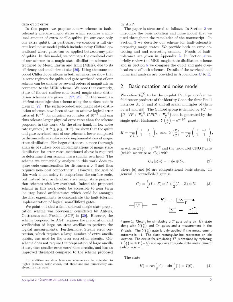
Figure 1: Circuit for simulating a T gate using an |H〉 statealong with Y
(π2
)and CY gates and a measurement in the
Y -basis. The Y(π2
)gate is only applied if the measurement
outcome is +1. The black rectangular box represents an idlelocation. The circuit for simulating T † is obtained by replacingY(π2
)with Y
(− π
2
)and applying this gate if the measurement
outcome is −1.
The state
|H〉 = cos π8 |0〉+ sin π8 |1〉 = T |0〉, (4)
Accepted in Quantum 2019-05-14, click title to verify 2
is the +1 eigenstate of the Hadamard operator and
T = e−iπY
8 =(
cos π8 − sin π8
sin π8 cos π8
)(5)
does not belong to the Clifford group2. We also write
| −H〉 = Y |H〉 (6)
as the −1 eigenstate of the Hadamard operator.The |H〉 state is an example of a magic state. Magic
states can be distilled to produce reliable states from alarger number of noisy copies using only stabilizer op-erations [11]. The reliable magic states can be used,together with stabilizer operations, as resource statesfor universal quantum computation. In particular, asshown in Fig. 1, the |H〉 state, along with Y
(π2
), CY ,
and a measurement in the Y -basis, can be used to simu-late a T gate. Note that some schemes choose to distillthe state
|Aπ4〉 ≡ 1√
2(|0〉+ ei
π4 |1〉) = ei
π8 HS†|H〉, (7)
which is equivalent to the |H〉 state up to products ofClifford gates. For instance, see the |Aπ
4〉 distillation
scheme in [11].Throughout this paper, we will use the following
circuit-level noise model in all simulations:
1. With probability p, each single-qubit gate locationis followed by a Pauli error drawn uniformly andindependently from {X,Y, Z}.
2. With probability p, each two-qubit gate is followedby a two-qubit Pauli error drawn uniformly andindependently from {I,X, Y, Z}⊗2 \ {I ⊗ I}.
3. With probability 2p3 , the preparation of the |0〉
state is replaced by |1〉 = X|0〉. Similarly, withprobability 2p
3 , the preparation of the |+〉 state isreplaced by |−〉 = Z|+〉.
4. With probability p, the preparation of the |H〉 stateis replaced by P |H〉 where P is a Pauli error drawnuniformly and independently from {X,Y, Z}.
5. With probability 2p3 , any single qubit measurement
has its outcome flipped.
6. Lastly, with probability p/100, each idle gate loca-tion is followed by a Pauli error drawn uniformlyand independently from {X,Y, Z}.
2Note that some references define the T gate as T =eiπ/4√
2
(1 1i −i
)which is a Clifford gate, while others define
T = diag(1, eiπ/4) which is non-Clifford but Clifford-equivalentto the gate we have defined as T .
Our assumption of p/100 idle error is valid for sys-tems whose gate errors are far from the limits set bycoherence times. For example, trapped ion experimentshave coherence times T2 = 2T1 on the order of 1 − 10seconds with gate times on the order of 10µs. This sug-gests idle error probabilities of 10−5 to 10−6, while twoqubit gate infidelities are on the order of 10−3 to 10−4
[31, 32]. On the other hand, the assumption may nothold in systems such as superconducting qubits, whosegates currently achieve infidelities near the coherencelimit [33]. Regardless, the concrete schemes we ana-lyze all use the same underlying quantum code familyand Clifford gate implementations, so we expect com-parisons between them to be robust.
In the following sections, all Clifford gates and re-source states will be encoded in the Steane code (seeSection 3) which, paired with flag qubits, will allowus to obtain encoded magic states with low overhead.The code distance will be increased through code con-catenation. Since the encoded version of the gates andstates are implemented in a fault-tolerant way, the fail-ure probability for each logical fault E of a gate G at aphysical error rate p resulting from the malignant eventmal(1)
E (where the superscript denotes the level of con-catenation) can be upper bounded as
Pr[mal(1)E |G, p] ≤
LG∑k=d d2 e
c(k)pk ≡ Γ(1)G , (8)
where c(k) denotes the number of weight-k errors whichcan lead to a logical fault and LG is the total number ofcircuit locations in the logical gate G. At the first con-catenation level, we performed Monte-Carlo simulationswith the above noise model to estimate the coefficientsc(k) for each logical gate and encoded states.
As was shown in [34–36], Eq. (8) can be generalizedto the level-l concatenation level where each physicalgate is replaced by its level-(l − 1) Rec3 (see [30] formore details). The error rate at the l-th concatenationlevel can be bounded as
Pr[mal(l)E |G, p] ≤LG∑
k=d d2 e
c(k)(
Γ(l−1)G
)k≡ Γ(l)
G . (9)
In other words, to estimate the logical failure rate ofa level-l gate, the probability of failure for all physi-cal gates G in our level-l simulation will be replaced by
3Rectangles (Rec’s) are encoded gates with trailing error cor-rection units. Extended rectangles, which are encoded gates withleading and trailing error correction units, are abbreviated asexRec’s.
Accepted in Quantum 2019-05-14, click title to verify 3

(a)
(b)
Figure 2: (a) Non-destructive measurement of the Hadamardoperator. (b) The CH gate can be decomposed into the gatesT , CZ and T †. As was shown in Fig. 1, the T gates can besimulated using only Clifford gates and an |H〉 resource state.
Pr[mal(l−1)E |G, p] obtained from a level-(l − 1) Monte-
Carlo simulation. For the physical error rates we con-sider, higher order terms are found to be relativelysmall, so we only estimate the leading order terms.More details can be found in [34–36].
3 Preparing magic states in the SteanecodeOne way to measure the Hadamard operator using onlyClifford gates and an |H〉 resource state is shown inFig. 2. To obtain resource states with high-fidelity(which is required for universal quantum computation),one method is to encode them into an error detectingor error correcting code and perform several rounds ofstate-distillation. If the physical error rate is belowsome threshold (which depends on the codes and dis-tillation routine), the error rate can be exponentiallysuppressed with the number of distillation rounds. An-other, more direct method, is to fault-tolerantly prepareresource states in a large distance error correcting code.The distance is chosen to obtain the desired logical errorsuppression. In particular, in the presence of noisy Clif-ford gates, distillation routines require encoded Cliffordoperations which can substantially increase the qubitand gate overhead of the routine. We now show how tofault-tolerantly prepare an |H〉 state using the Steanecode and flag-qubits in order to achieve a lower gate andqubit overhead. We will compare the overhead require-ments of our methods with that of the Meier-Eastin-Knill (MEK) distillation routine [26]. A review of theMEK distillation routine is given in Section 4.
The Steane code is a [[7, 1, 3]] CSS (Calderbank-Shor-Steane) code [37, 38] with stabilizer generators and log-ical operators given in Table 1. The Steane code has
[[7, 1, 3]] Steane code [[4, 2, 2]] codeg1 = XIXIXIX g1 = XXXX
g2 = IIIXXXX g2 = ZZZZ
g3 = IXXIIXX
g4 = ZIZIZIZ
g5 = IIIZZZZ
g6 = IZZIIZZ
X = X⊗7 X1 = XXII, X2 = XIIX
Z = Z⊗7 Z1 = ZIIZ, Z2 = ZZII
Table 1: Stabilizer generators and logical operators of the[[7, 1, 3]] Steane code and the [[4, 2, 2]] error detecting code.
the property that all Clifford gates can be implementedtransversally. In particular, the logical Hadamard op-erator is given by H = H⊗7. The fault-tolerant prepa-ration of an encoded |Aπ
4〉 (see Eq. (7)) state has been
previously analyzed in [30]. However, Steane error cor-rection (not to confuse with the Steane code) was usedfor the EC units and cat states were fault-tolerantlyprepared in order to measure T XT † 4. The high costfor preparing cat states and implementing Steane EC’sresults in a large qubit overhead.
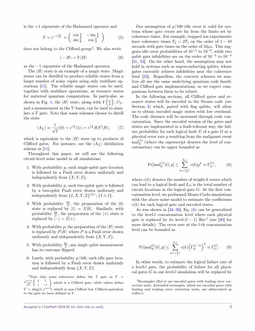
Instead of using Steane-EC circuits, in this work weconsider an EC circuit recently introduced by Reichardt[25] for measuring the stabilizers of the Steane code withlow circuit-depth and which requires only three ancillaqubits (see Fig. 3). The small qubit overhead is achievedwith the use of flag qubits which can detect events whereerrors from a single fault spread to an X or Z error ofweight greater than one on the data. The fault-tolerantproperties of the circuit are discussed in Appendix A.1.
Flag-qubits can also be used to fault-tolerantly mea-sure the logical Hadamard operator with only one extraancilla qubit (and thus do not require the fault-tolerantpreparation of cat states). In an error detection scheme,where the |H〉 state is rejected if errors are detected,the circuit in Fig. 5a can be used to measure the log-ical Hadamard operator. If a fault results in an X orZ data qubit error of weight greater than one, the flagqubit (ancilla prepared in the |0〉 state) will be mea-sured as −1 and the |H〉 state will be rejected. Thefull error detecting scheme is shown in Fig. 5b 5. Notethat our scheme uses only 10-qubits and is shown to befault-tolerant in Appendix A.2.
Error detection schemes have extra overhead arising
4Note that the T gates considered in this paper are Clifford-equivalent to the T gates considered in [30]
5In both Fig. 5a and Fig. 5b, the controlled Hadamard gatesare implemented as shown in Fig. 2 and for concatenation levelsgreater than one, the T gates are implemented as in Fig. 1. SeeAppendix C for more details.
Accepted in Quantum 2019-05-14, click title to verify 4
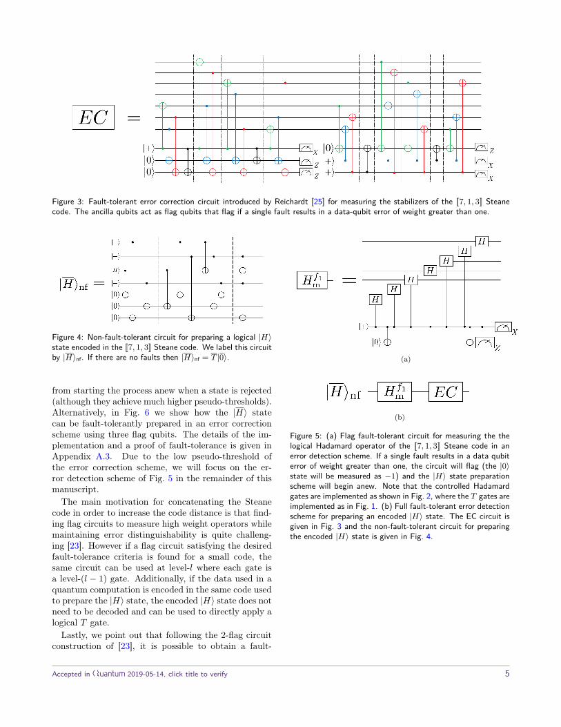
Figure 3: Fault-tolerant error correction circuit introduced by Reichardt [25] for measuring the stabilizers of the [[7, 1, 3]] Steanecode. The ancilla qubits act as flag qubits that flag if a single fault results in a data-qubit error of weight greater than one.
Figure 4: Non-fault-tolerant circuit for preparing a logical |H〉state encoded in the [[7, 1, 3]] Steane code. We label this circuitby |H〉nf. If there are no faults then |H〉nf = T |0〉.
from starting the process anew when a state is rejected(although they achieve much higher pseudo-thresholds).Alternatively, in Fig. 6 we show how the |H〉 statecan be fault-tolerantly prepared in an error correctionscheme using three flag qubits. The details of the im-plementation and a proof of fault-tolerance is given inAppendix A.3. Due to the low pseudo-threshold ofthe error correction scheme, we will focus on the er-ror detection scheme of Fig. 5 in the remainder of thismanuscript.
The main motivation for concatenating the Steanecode in order to increase the code distance is that find-ing flag circuits to measure high weight operators whilemaintaining error distinguishability is quite challeng-ing [23]. However if a flag circuit satisfying the desiredfault-tolerance criteria is found for a small code, thesame circuit can be used at level-l where each gate isa level-(l − 1) gate. Additionally, if the data used in aquantum computation is encoded in the same code usedto prepare the |H〉 state, the encoded |H〉 state does notneed to be decoded and can be used to directly apply alogical T gate.
Lastly, we point out that following the 2-flag circuitconstruction of [23], it is possible to obtain a fault-
(a)
(b)
Figure 5: (a) Flag fault-tolerant circuit for measuring the thelogical Hadamard operator of the [[7, 1, 3]] Steane code in anerror detection scheme. If a single fault results in a data qubiterror of weight greater than one, the circuit will flag (the |0〉state will be measured as −1) and the |H〉 state preparationscheme will begin anew. Note that the controlled Hadamardgates are implemented as shown in Fig. 2, where the T gates areimplemented as in Fig. 1. (b) Full fault-tolerant error detectionscheme for preparing an encoded |H〉 state. The EC circuit isgiven in Fig. 3 and the non-fault-tolerant circuit for preparingthe encoded |H〉 state is given in Fig. 4.
Accepted in Quantum 2019-05-14, click title to verify 5

(a)
(b)
Figure 6: (a) Flag fault-tolerant circuit for measuring the the logical Hadamard operator of the [[7, 1, 3]] Steane code. The extraflag qubits are used to localize errors occurring near the fourth controlled-Hadamard gate since these cannot be distinguished fromerrors occurring at the other controlled-Hadamard gates. Note that in order to distinguish errors from faults at other locations,the full six bit error syndrome must be considered. That is, we cannot correct X and Z errors separately as is usually done inCSS constructions. (b) Full fault-tolerant error correction scheme for preparing an encoded |H〉 state. The EC circuit is given inFig. 3 and the non-fault-tolerant circuit for preparing the encoded |H〉 state is given in Fig. 4. If a flag occurs in the third Hf2
m
measurement, an extra round of EC is performed.
Figure 7: 2-flag circuit for measuring the logical Hadamard operator of the [[17, 1, 5]] color code. This circuit can be used in anerror detection scheme for fault-tolerantly preparing an |H〉 state encoded in the [[17, 1, 5]] color code. If there are v ≤ 2 faultswhich cause a data qubit error of weight greater than v, at least one of the flag qubits will flag and the |H〉 state will be rejected.
Accepted in Quantum 2019-05-14, click title to verify 6

tolerant circuit to measure the logical Hadamard op-erator of the [[17, 1, 5]] color code. The circuit is givenin Fig. 7 and can be used in an error detection schemeanalogous to that of Fig. 5. EC circuits for measur-ing the stabilizers of the [[17, 1, 5]] color code were ob-tained in [23] and require at most four ancilla qubits.One could also measure the stabilizers using standardtopological methods at the cost of requiring O(n) an-cillas. This circuit could be useful if a higher distanceis required prior to concatenation or if a hybrid state-preparation and magic state distillation scheme is used(see Section 5 for more details).
4 Meier-Eastin-Knill distillation circuitsIn the MEK distillation protocol, |H〉 states are encodedin the [[4, 2, 2]] error detecting code, whose stabilizer gen-erators and logical operators are given in Table 1. Forthe [[4, 2, 2]] code, the operator H⊗4 is a valid encodedgate and performs the operation H1H2SWAP12 whereSWAP12 swaps the two encoded qubits. The circuit inFig. 8 performs an encoded measurement of H1H2 ona pair of encoded |H〉 states and measures the stabiliz-ers of the [[4, 2, 2]] code (note that the circuit applies aHadamard gate to one of the two encoded qubits). Theroutine accepts the pair of |H〉 states if both the H⊗4
and syndrome measurements are trivial. More detailscan be found in [26].
Suppose that the desired output failure probability ofthe input resource states is O(p2l). Note that a singlefault in some of the two-qubit gates in Fig. 8 can resultin multi-qubit errors on the data that go undetected6.Since all of the gates in Fig. 8 fail following the noisemodel described in Section 2, they must be encoded inanother code (which we choose to be the level-l con-catenated Steane code) in order to achieve the desiredlogical error rate in the output resource states. To pro-vide a fair comparison between the overhead costs ofour state preparation scheme with flag qubits and theMEK scheme, all exRec’s contain the EC unit of Fig. 3.These features will play an important role when evalu-ating the qubit and gate overhead of the MEK scheme.
Many magic state distillation protocols use a random-ization called twirling [11] to diagonalize each magicstate in a convenient basis. This greatly simplifies theanalysis so that the acceptance probabilities and logi-cal error rates can be found in closed form. However,twirling is not necessary in a physical implementation,since there is always another protocol without the ran-domization that uses the optimal choice of gates [39].
6This is due to the fact that magic state distillation circuits arefault-tolerant for noise models where errors are only introducedin resource states.
In our case, we observe that the logical error rates in-crease if we twirl, so we simply use the input states asthey occur.
5 Resource overhead comparisonIn this section we compare the overhead cost ofour fault-tolerant magic state preparation scheme forpreparing an encoded |H〉 state in the concatenatedSteane code to the overhead cost of the MEK scheme fordistilling |H〉 states (also encoded in the concatenatedSteane code). In particular, we will compare the qubitand gate overhead cost of both schemes. In what fol-lows, a level-l state or gate will always correspond to itsencoded version in l concatenation levels of the Steanecode.
For the MEK magic state distillation protocol, weconsider two different approaches. In the first approach,physical |H〉 states are teleported into level-2 |H〉 statesand a subsequent round of MEK (with level-2 Cliffordgates) is applied to produce a state with a logical errorrate well-approximated by the form ap2 + bp4 below thelevel-2 pseudo-threshold. The O(p2) term is dominantat low error rates, and the O(p4) term is dominant at er-ror rates near the pseudo-threshold. To obtain furthererror suppression, we then teleport the distilled stateinto a level-3 state and perform a level-3 round of MEKto obtain a state with a logical error rate of the forma′p4 + b′p8. An additional round of MEK could be per-formed to obtain an |H〉 state with logical error rateO(p8). However, for the physical error rates consideredin this work (p ∈ [10−5, 10−4]), we found that there isno advantage in doing so.
In the second approach, we consider a hybrid schemewhere a level-2 |H〉 state is first prepared using ourfault-tolerant flag preparation scheme. The state is thenteleported into a level-3 state and a round of MEK isperformed resulting in an |H〉 state with logical errorrate O(p8). All teleportation schemes are performedusing the methods described in Appendix B.
The qubit and gate overhead results for the magicstate preparation scheme with flag qubits and the MEKschemes are shown in Figs. 9 to 11. Details of the analy-sis leading to the plots are given in Appendices C and D.
Comparing the results, it is clear that the qubit andgate overhead cost of the fault-tolerant |H〉 state prepa-ration scheme of Fig. 5 is substantially smaller thanschemes involving MEK. The primary reasons for thisare due to the high pseudo-threshold of the error de-tection scheme as well as the small size of the circuitscompared to the circuits used by MEK (where we usedthe teleportation scheme of Appendix B to inject statesat a higher concatenation level). Further, note that thehybrid scheme (Fig. 11) has smaller qubit and gate over-
Accepted in Quantum 2019-05-14, click title to verify 7

(a)
(b)
Figure 8: (a) First half of the MEK distillation circuit. (b) Second half of the MEK distillation circuit. The circuit is the same asgiven in [26] but has been written in detail to illustrate the idle qubit locations (filled rectangles). We reuse the |H〉 ancilla qubitinstead of doing gates in parallel in order to minimize the overhead cost. A total of four CH gates are required to measure theoperator H1H2.
Figure 9: Qubit and gate overhead for our fault-tolerant magic state preparation scheme using flag qubits. We considering targetlogical failure rates ranging between 10−6 to 10−9. The different jumps in the curves indicate that an additional concatenationlevel is required in order to achieve the desired logical failure rate. Note that the y axis of the qubit overhead plot is not displayedon a log scale. This is to show the increase in overhead cost due to the probability of rejecting a state when implementing theerror detection scheme.
Accepted in Quantum 2019-05-14, click title to verify 8
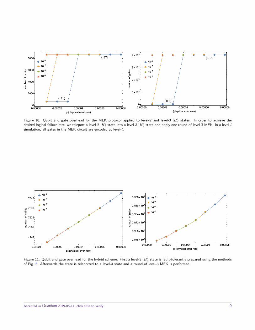
Figure 10: Qubit and gate overhead for the MEK protocol applied to level-2 and level-3 |H〉 states. In order to achieve thedesired logical failure rate, we teleport a level-2 |H〉 state into a level-3 |H〉 state and apply one round of level-3 MEK. In a level-lsimulation, all gates in the MEK circuit are encoded at level-l.
Figure 11: Qubit and gate overhead for the hybrid scheme. First a level-2 |H〉 state is fault-tolerantly prepared using the methodsof Fig. 5. Afterwards the state is teleported to a level-3 state and a round of level-3 MEK is performed.
Accepted in Quantum 2019-05-14, click title to verify 9

head costs compared to the full MEK scheme (Fig. 10),although the overhead is still much larger than the errordetection scheme using flag qubits.
Lastly, we point out that due to the lower logical fail-ure rates of the error detection scheme using flag qubits,three concatenation levels were sufficient to achieve log-ical failure rates of 10−9 for larger physical error ratescompared to MEK (the same is true for other targetlogical failure rates). For example, suppose one wantsto achieve a logical failure rate pL ≤ 10−9. In our errordetection scheme, one must use at least four concatena-tion levels for physical error rates p > 6×10⁻⁵. For theMEK scheme, one requires four concatenation levels forphysical error rates p > 4 × 10⁻⁵. Hence for physicalerror rates 4 × 10⁻⁵ ≤ p ≤ 6 × 10⁻⁵, the error detec-tion scheme will require fewer qubits by several ordersof magnitude compared to MEK (see Figs. 9 and 10).
6 ConclusionThe high cost of universal fault-tolerant logic is a chal-lenging and enduring problem. In this work, we proposean alternative to magic state distillation that is basedon recently discovered flag fault-tolerance techniques.We have designed a flag-based magic state preparationscheme that reduces the number of qubits and opera-tions to prepare a reliable magic state, and does so byorders of magnitude in some error regimes. Further-more, the error-detection-based state preparation cir-cuit at level-1 has a high pseudothreshold and uses atotal of 10 qubits. The circuit accepts around 80% ofthe time and has logical error rates near 10−4 at physi-cal error rates near 3×10⁻³ (see Table 4), making it aninteresting candidate for experimental consideration.
The magic state preparation scheme relies on atransversal Hadamard operator and a flag circuit formeasuring it fault-tolerantly. So that the operator’sweight does not grow, we concatenate the code with it-self to achieve some low logical error rate. The thresholdis ultimately that of the concatenated Steane code in allof the schemes we analyze. It would be interesting toaccount for more realistic constraints on qubit connec-tivity, and to consider how to extend these techniquesto families of higher distance (non-concatenated) codes,but we leave this to future work.
Another interesting application of our work is its usein state injection schemes [29, 40]. Using the fault-tolerant circuits for distance-three and five color codesin Figs. 5 and 7 (the w-flag circuits described in [23]could also be used for higher distance color codes), en-coded magic states with logical failure rates of O(p2)and O(p3) can be produced. Lattice surgery techniquescould then be performed to further distill the inputmagic states [40, 41]. We note that the state injec-
tion scheme in [29] produces encoded magic states withlogical failure rate O(p) and thus for low enough physi-cal error rates, our approach could achieve lower logicalfailure rates.
If codes such as topological codes were used to per-form the MEK protocol at high physical error rates,then magic state distillation might outperform the flag-based scheme, since a large number of concatenationlevels would be necessary. However, the ideas we havepresented may be broadly applicable to improve thepseudothreshold of magic state preparation circuits us-ing codes other than the Steane code. In this direction,we have given a 2-flag circuit for fault-tolerantly mea-suring logical Hadamard of the 17-qubit color code. Iflower logical error rates are needed, states could thenbe used in a hybrid approach that takes advantage ofthe topological code threshold. Lastly, one could usethe w-flag circuit construction and EC circuits of [23]to fault-tolerantly prepare magic states for the familyof color codes on a hexagonal lattice.
7 AcknowledgementsC.C. acknowledges IBM for its hospitality where all ofthis work was completed. C.C. also acknowledges thesupport of NSERC through the PGS D scholarship. Wethank Sergey Bravyi, Earl Campbell, Tomas Jochym-O’Connor, and Ted Yoder for useful discussions. Wethank Earl Campbell for sharing observations about theMEK protocol.
Accepted in Quantum 2019-05-14, click title to verify 10

References[1] P.W. Shor. Algorithms for quantum computa-
tion: Discrete logarithms and factoring. Proceed-ings., 35th Annual Symposium on Foundations ofComputer Science, pages 124–134, 1994. DOI:10.1109/SFCS.1994.365700.
[2] Quantum Algorithm Zoo. https://math.nist.gov/quantum/zoo/. Last Accessed: 2018-10-31.
[3] Bryan Eastin and Emanuel Knill. Restrictions ontransversal encoded quantum gate sets. Phys. Rev.Lett., 102:110502, Mar 2009. DOI: 10.1103/Phys-RevLett.102.110502. URL https://link.aps.org/doi/10.1103/PhysRevLett.102.110502.
[4] E. Knill, R. Laflamme, and W. Zurek. ThresholdAccuracy for Quantum Computation. arXive-prints, art. quant-ph/9610011, Oct 1996.URL https://ui.adsabs.harvard.edu/abs/1996quant.ph.10011K.
[5] Tomas Jochym-O’Connor and RaymondLaflamme. Using concatenated quantum codesfor universal fault-tolerant quantum gates. Phys.Rev. Lett., 112:010505, 2014. DOI: 10.1103/Phys-RevLett.112.010505. URL http://link.aps.org/doi/10.1103/PhysRevLett.112.010505.
[6] Adam Paetznick and Ben W. Reichardt. Univer-sal fault-tolerant quantum computation with onlytransversal gates and error correction. Phys. Rev.Lett., 111:090505, Aug 2013. DOI: 10.1103/Phys-RevLett.111.090505. URL https://link.aps.org/doi/10.1103/PhysRevLett.111.090505.
[7] Jonas T. Anderson, Guillaume Duclos-Cianci, andDavid Poulin. Phys. Rev. Lett., 113:080501, Aug2014. DOI: 10.1103/PhysRevLett.113.080501.
[8] Héctor Bombín. Dimensional jump in quan-tum error correction. New Journal of Physics,18(4):043038, apr 2016. DOI: 10.1088/1367-2630/18/4/043038. URL https://doi.org/10.1088%2F1367-2630%2F18%2F4%2F043038.
[9] Theodore J. Yoder, Ryuji Takagi, and Isaac L.Chuang. Universal fault-tolerant gates on con-catenated stabilizer codes. Phys. Rev. X,6:031039, Sep 2016. DOI: 10.1103/Phys-RevX.6.031039. URL https://link.aps.org/doi/10.1103/PhysRevX.6.031039.
[10] E. Knill. Fault-Tolerant Postselected QuantumComputation: Schemes. arXiv e-prints, art. quant-ph/0402171, Feb 2004. URL https://ui.adsabs.harvard.edu/abs/2004quant.ph..2171K.
[11] Sergey Bravyi and Alexei Kitaev. Univer-sal quantum computation with ideal cliffordgates and noisy ancillas. Phys. Rev. A,71:022316, Feb 2005. DOI: 10.1103/Phys-
RevA.71.022316. URL https://link.aps.org/doi/10.1103/PhysRevA.71.022316.
[12] Jeongwan Haah, Matthew B. Hastings, D. Poulin,and D. Wecker. Magic state distillation withlow space overhead and optimal asymptotic in-put count. Quantum, 1:31, October 2017. ISSN2521-327X. DOI: 10.22331/q-2017-10-03-31. URLhttps://doi.org/10.22331/q-2017-10-03-31.
[13] Jeongwan Haah and Matthew B. Hastings. Codesand Protocols for Distilling T , controlled-S, andToffoli Gates. Quantum, 2:71, June 2018. ISSN2521-327X. DOI: 10.22331/q-2018-06-07-71. URLhttps://doi.org/10.22331/q-2018-06-07-71.
[14] Matthew B. Hastings and Jeongwan Haah. Distil-lation with sublogarithmic overhead. Phys. Rev.Lett., 120:050504, Jan 2018. DOI: 10.1103/Phys-RevLett.120.050504. URL https://link.aps.org/doi/10.1103/PhysRevLett.120.050504.
[15] Jeongwan Haah, Matthew B. Hastings, DavidPoulin, and Dave Wecker. Magic state distillationat intermediate size. Quantum Info. Comput., 18(1& 2):97–165, February 2018. ISSN 0114-0140.
[16] Austin G. Fowler, Matteo Mariantoni, John M.Martinis, and Andrew N. Cleland. Surface codes:Towards practical large-scale quantum computa-tion. Phys. Rev. A, 86:032324, Sep 2012. DOI:10.1103/PhysRevA.86.032324.
[17] Hayato Goto. Step-by-step magic state encod-ing for efficient fault-tolerant quantum computa-tion. Scientific Reports, (4):7501, 2014. DOI:10.1038/srep07501.
[18] Joe O’Gorman and Earl T. Campbell. Quan-tum computation with realistic magic-statefactories. Phys. Rev. A, 95:032338, Mar2017. DOI: 10.1103/PhysRevA.95.032338.URL https://link.aps.org/doi/10.1103/PhysRevA.95.032338.
[19] Daniel Litinski. A Game of Surface Codes: Large-Scale Quantum Computing with Lattice Surgery.Quantum, 3:128, March 2019. ISSN 2521-327X.DOI: 10.22331/q-2019-03-05-128. URL https://doi.org/10.22331/q-2019-03-05-128.
[20] Theodore J. Yoder and Isaac H. Kim. The surfacecode with a twist. Quantum, 1:2, April 2017. ISSN2521-327X. DOI: 10.22331/q-2017-04-25-2. URLhttps://doi.org/10.22331/q-2017-04-25-2.
[21] Rui Chao and Ben W. Reichardt. Quantum errorcorrection with only two extra qubits. Phys. Rev.Lett., 121:050502, Aug 2018. DOI: 10.1103/Phys-RevLett.121.050502. URL https://link.aps.org/doi/10.1103/PhysRevLett.121.050502.
[22] Rui Chao and Ben W. Reichardt. Fault-tolerant quantum computation with few qubits.
Accepted in Quantum 2019-05-14, click title to verify 11

arXiv:quant-ph/1705.05365, 2017. URL https://arxiv.org/abs/1705.05365.
[23] Christopher Chamberland and Michael E. Bever-land. Flag fault-tolerant error correction with ar-bitrary distance codes. Quantum, 2:53, February2018. ISSN 2521-327X. DOI: 10.22331/q-2018-02-08-53. URL https://doi.org/10.22331/q-2018-02-08-53.
[24] Theerapat Tansuwannont, Christopher Cham-berland, and Debbie Leung. Flag fault-toleranterror correction, measurement, and quantumcomputation for cyclic CSS codes. arXive-prints, art. arXiv:1803.09758, Mar 2018.URL https://ui.adsabs.harvard.edu/abs/2018arXiv180309758T.
[25] Ben W. Reichardt. Fault-tolerant quantum er-ror correction for steane’s seven-qubit color codewith few or no extra qubits. arXiv:quant-ph/1804.06995, 2018. URL https://arxiv.org/abs/1804.06995.
[26] Adam M. Meier, Bryan Eastin, and Emanuel Knill.Magic-state distillation with the four-qubit code.Quantum Info. Comput., 13(3-4):0195–0209, 2013.
[27] Austin G. Fowler and Craig Gidney. Lowoverhead quantum computation using latticesurgery. arXiv e-prints, art. arXiv:1808.06709,Aug 2018. URL https://ui.adsabs.harvard.edu/abs/2018arXiv180806709F.
[28] Craig Gidney and Austin G. Fowler. Efficientmagic state factories with a catalyzed |CCZ〉to 2|T 〉 transformation. Quantum, 3:135, April2019. ISSN 2521-327X. DOI: 10.22331/q-2019-04-30-135. URL https://doi.org/10.22331/q-2019-04-30-135.
[29] Ying Li. A magic state’s fidelity can besuperior to the operations that created it.New Journal of Physics, 17(2):023037, feb2015. DOI: 10.1088/1367-2630/17/2/023037.URL https://doi.org/10.1088%2F1367-2630%2F17%2F2%2F023037.
[30] Panos Aliferis, Daniel Gottesman, and JohnPreskill. Quantum accuracy threshold for con-catenated distance-3 codes. Quantum Info. Com-put., 6(2):97–165, March 2006. ISSN 1533-7146. URL http://dl.acm.org/citation.cfm?id=2011665.2011666.
[31] Colin J Trout, Muyuan Li, Mauricio Gutiérrez,Yukai Wu, Sheng-Tao Wang, Luming Duan, andKenneth R Brown. Simulating the performanceof a distance-3 surface code in a linear ion trap.New Journal of Physics, 20(4):043038, apr 2018.DOI: 10.1088/1367-2630/aab341. URL https://doi.org/10.1088%2F1367-2630%2Faab341.
[32] A. Bermudez, X. Xu, M. Gutiérrez, S. C.
Benjamin, and M. Müller. Fault-tolerant pro-tection of near-term trapped-ion topologicalqubits under realistic noise sources. arXive-prints, art. arXiv:1810.09199, Oct 2018.URL https://ui.adsabs.harvard.edu/abs/2018arXiv181009199B.
[33] Maika Takita, Andrew W. Cross, A. D. Córcoles,Jerry M. Chow, and Jay M. Gambetta. Experi-mental demonstration of fault-tolerant state prepa-ration with superconducting qubits. Phys. Rev.Lett., 119:180501, Oct 2017. DOI: 10.1103/Phys-RevLett.119.180501. URL https://link.aps.org/doi/10.1103/PhysRevLett.119.180501.
[34] Adam Paetznick and Ben W. Reichardt. Fault-tolerant ancilla preparation and noise thresholdlower bounds for the 23-qubit golay code. Quan-tum Info. Comput., 12(11-12):1034–1080, Novem-ber 2012. ISSN 1533-7146. URL http://dl.acm.org/citation.cfm?id=2481569.2481579.
[35] Christopher Chamberland, Tomas Jochym-O’Connor, and Raymond Laflamme. Thresh-olds for universal concatenated quantumcodes. Phys. Rev. Lett., 117:010501, Jun2016. DOI: 10.1103/PhysRevLett.117.010501.URL https://link.aps.org/doi/10.1103/PhysRevLett.117.010501.
[36] Christopher Chamberland, Tomas Jochym-O’Connor, and Raymond Laflamme. Overheadanalysis of universal concatenated quantumcodes. Phys. Rev. A, 95:022313, Feb 2017. DOI:10.1103/PhysRevA.95.022313.
[37] A. R. Calderbank and Peter W. Shor. Goodquantum error-correcting codes exist. Phys. Rev.A, 54:1098–1105, Aug 1996. DOI: 10.1103/Phys-RevA.54.1098.
[38] Andrew W. Steane. Multiple-Particle Interferenceand Quantum Error Correction. Proc. Roy. Soc.Lond., 452:2551–2577, 1996. URL http://www.jstor.org/stable/52827.
[39] Earl Campbell and Dan Browne. On the structureof protocols for magic state distillation. LectureNotes in Computer Science, 5906.
[40] Andrew J. Landahl and Ciaran Ryan-Anderson.Quantum computing by color-code lattice surgery.arXiv e-prints, art. arXiv:1407.5103, Jul 2014.URL https://ui.adsabs.harvard.edu/abs/2014arXiv1407.5103L.
[41] Christophe Vuillot, Lingling Lao, Ben Criger, Car-men García Almudéver, Koen Bertels, and Bar-bara M Terhal. Code deformation and latticesurgery are gauge fixing. New Journal of Physics,21(3):033028, mar 2019. DOI: 10.1088/1367-2630/ab0199. URL https://doi.org/10.1088%2F1367-2630%2Fab0199.
Accepted in Quantum 2019-05-14, click title to verify 12

[42] Daniel Gottesman. An introduction to quantum er-ror correction and fault-tolerant quantum compu-tation. Proceedings of Symposia in Applied Math-ematics, 68:13–58, 2010. URL https://arxiv.org/abs/0904.2557.
[43] Emanuel Knill. Quantum computing with realisti-cally noisy devices. Nature, 434(7029):39–44, 2005.DOI: 10.1038/nature03350.
[44] Panagiotis Panos Aliferis. Level reduction and thequantum threshold theorem. PhD thesis, CaliforniaInstitute of Technology, 2007.
[45] Qiskit: an open source quantum computing frame-work. https://github.com/Qiskit. Last Ac-cessed: 2018-10-31.
Accepted in Quantum 2019-05-14, click title to verify 13

A Proof of fault-tolerance for the magicstate preparation schemesIn this appendix we provide proofs showing that ourmagic state preparation schemes for the |H〉 state arefault-tolerant. In what follows, a state-preparationscheme will be called fault-tolerant if the following twoconditions are satisfied [42]
Definition 1. Fault-tolerant state preparationFor t = b(d−1)/2c, a state-preparation protocol using
a distance-d stabilizer code C is t-fault-tolerant if thefollowing two conditions are satisfied:
1. If there are s faults during the state-preparationprotocol with s ≤ t, the resulting state differs froma codeword by an error of at most weight s.
2. If there are s faults during the state-preparationprotocol with s ≤ t, then ideally decoding the out-put state results in the same state that would be ob-tained from the fault-free state-preparation scheme.
In Definition 1, ideally decoding is equivalent to per-forming fault-free error correction. Now suppose |ψ〉is the encoded state to be prepared. If there are s ≤ tfaults during a state-preparation protocol satisfying thecriteria in Definition 1, then the output state will havethe form E|ψ〉 with wt(E) ≤ s (the output state willencode the correct state with no more than s errors).
For CSS codes, this definition can be applied inde-pendently to X and Z errors.
A.1 Error correction circuitIn this section we provide more details on the propertiesof the EC circuit of Fig. 3 which is used in all of ourschemes.
The first half of the circuit measures the XIXIXIX(green CNOT’s), IIIZZZZ (blue CNOT’s) andIZZIIZZ (red CNOT’s) stabilizers of the Steane code.The second half of the circuit measures the remain-ing stabilizers. Given that the CNOT gates are nottransversal, it is possible for a single fault to result in aweight-two X or Z data-qubit error. However the an-cilla qubits also act as flag qubits which can be used todetect such events.
Let us assume that a single-fault occurs. For the firsthalf of the EC circuit, the possible weight-two errorsthat can arise from a single fault are Z4Z6, Z3Z7, andX3X7. In the case of Z4Z6 and Z3Z7, the measurementin the X-basis will flag (with the two Z-basis measure-ments being +1), at which point the entire syndromemeasurement is repeated. Since Z4Z6 and Z3Z7 are er-rors that have different syndromes than all other errorsarising from a single fault leading to a −+ + measure-ment outcome of the first three ancilla qubits, after thesyndrome measurement is repeated these errors can bedistinguished and corrected.
The same argument applies to the case where a singlefault leads to the X3X7 data-qubit error. But this timethe X4 error has the same syndrome as X3X7 (s(X4) =s(X3X7) = 010000). However, the faults causing anX3X4 error result in a + − − measurement outcomeof the first three ancillas whereas X4 results in + − +.Thus when the syndrome measurement is repeated andthe flag outcomes are taken into account, the errors canbe distinguished and corrected.
An analogous analysis can be applied to the secondhalf of the EC circuit. See [25] for more details.
A.2 Fault-tolerance proof for the error detectionschemeRecall that the error detection scheme can be decom-posed into three components as shown in Fig. 5b. Sincet = 1 for the [[7, 1, 3]] Steane code, we must show thatif a single fault occurs in any of the three components,both criteria in Definition 1 will be satisfied.
Case 1: fault in |H〉nf (see Fig. 4). Since the Steanecode is a perfect CSS code and the |H〉nf circuit is notfault-tolerant, the output state of the first componentwill have the form
|ψ(1)〉 = E(x)i E
(z)j E
(x)i E
(z)j |H〉, (10)
where E(x)i ∈ {I,Xi} and E
(z)j ∈ {I, Zj} are single-
qubit errors on qubits i and j and E(x)i ∈ {I,X}, E(z)
j ∈{I, Z} are logical operators of the Steane code.
Now the output state of the second component ofFig. 5b, including the contribution from the first ancillaqubit (which will subsequently be measured in the X-basis), is given by
|ψ(2)〉 = 12
{(E
(x)i E
(z)j E
(x)i E
(z)j + E
(z)i E
(x)j E
(z)i E
(x)j
)|H〉|+〉+
(E
(x)i E
(z)j E
(x)i E
(z)j − E
(z)i E
(x)j E
(z)i E
(x)j
)|H〉|−〉
}.
(11)
If E(x)i 6= I or E(z)
j 6= I, then the single-qubit error will be detected by the subsequent EC and the state will be
Accepted in Quantum 2019-05-14, click title to verify 14

rejected. Thus let us assume that E(x)i = E
(z)j = I so
that
|ψ(2)〉 = 12
{(E
(x)i E
(z)j + E
(z)i E
(x)j
)|H〉|+〉
+(E
(x)i E
(z)j − E
(z)i E
(x)j
)|H〉|−〉
}. (12)
If E(x)i E
(z)j = Y , then |ψ(2)〉 = | − H〉|−〉 and the
ancilla measurement will be −1 resulting in rejection.Thus suppose that E(x)
i E(z)j is X or Z so that
|ψ(2)〉 = 1√2
{|H〉|+〉 ∓ i| −H〉|−〉
}, (13)
where we used the identities H = 1√2 (X +Z), XHX =
1√2 (X − Z) and ZHZ = 1√
2 (Z − X). From Eq. (13),we see that |ψ(2)〉 will be accepted with probability 1/2resulting in the state |H〉. Thus if a single fault occursin the first component of Fig. 5b, an accepted state willbe |H〉.
Case 2: fault in Hf1m (see Fig. 5a). Since there are no
faults in |H〉nf, the input to the circuit will be |H〉. Ifthe fault results in any measurement outcome to be −1,the state will be rejected. Thus we only consider faultssuch that the measurement outcome of all ancilla’s is+1. Since the circuit will flag if a single fault resultsin a data-qubit error of weight greater than one, theoutput state of the circuit will be |ψ(2)
out〉 = E(x)i E
(z)j |H〉
with wt(E(x)i ) ≤ 1 and wt(E(z)
j ) ≤ 1. If E(x)i E
(z)j is non-
trivial, it will be detected by the subsequent EC circuitand the state will be rejected. Hence an accepted statewill be |H〉.
Case 3: fault in the EC circuit (see Fig. 3). Sincethere are no faults in the first two components of Fig. 5b,the input state to the EC will be |ψ(3)〉 = |H〉. If a faultcauses a non-trivial measurement, the state will be re-jected. Hence let us consider the case where a singlefault results in an error which goes undetected. A sin-gle fault in the EC can result in a data-qubit error ofthe form E
(x)i E
(z)j where wt(E(x)
i ) ≤ 1 and wt(E(z)j ) ≤ 1
without any flags7. However, due to the fault-tolerantproperties of the EC, a fault resulting in a data errorwith wt(E(x)
i ) ≥ 2 or wt(E(z)j ) ≥ 2 will cause one of the
flag qubits to flag. Hence if the state is accepted (allmeasurements are trivial), the output state of the ECwill have the form
|ψout〉 = E(x)i E
(z)j |H〉, (14)
with wt(E(x)i ) ≤ 1 and wt(E(z)
j ) ≤ 1. Since errors ofthe form E = XiZj are correctable by the Steane code,
7As an example, consider the error Z ⊗X on the fourth blackCNOT of Fig. 3 which results in the data-qubit error X6Z7.
(a)
(b)
Figure 12: (a) Propagation of X errors through the control-qubit of a controlled-Hadamard gate. This induces a Hadamarderror on the target qubit. (b) Propagation of a Z error throughthe control-qubit of a controlled-Hadamard gate.
fault-free error correction of an accepted state of theprotocol in Fig. 5b will always result in the state |H〉.We conclude that if there is at most one fault, bothcriteria in Definition 1 will be satisfied.
A.3 Fault-tolerance proof for the error correctionschemeA.3.1 Error distinguishability
Recall that for the error correction scheme, the circuitfor measuring the logical Hadamard operator is given inFig. 6a. The first thing to notice is that the controlled-Hadamard gates are implemented in a different ordercompared to the gates in Fig. 5a. If a fault occurs atone of the controlled-Hadamard gates resulting in anX or Y error on the control-qubit, the resulting dataqubit error can be expressed as a product of Hadamarderrors and Pauli errors (see Fig. 12). For the secondto sixth controlled-Hadamard gates, all errors arisingfrom a single fault at one of these locations which prop-agate to the data qubits (causing at least one of the flagqubits to flag) must be distinguishable (since H = H⊗7,a fault occurring at the first controlled-Hadamard gatewill result in an X and Z data-qubit error of weightat most one). This is only possible if errors are cor-rected based on their full syndrome8 and with a care-fully chosen ordering of the controlled-Hadamard gates.Performing a numerical search of all 7! = 5040 per-mutations of the controlled-Hadamard gates, there was
8Instead of using a three-bit syndrome for correcting X er-rors and separately using the other three-bit syndrome to correctZ errors, one would use the full six-bit syndrome to correct thedata errors. Note that we only correct using the full six-bit syn-drome if there are flags. Otherwise, we perform the standard CSScorrection of X and Z errors separately.
Accepted in Quantum 2019-05-14, click title to verify 15

no permutation that allowed all possible errors (arisingfrom a single fault) to be distinguished. However, ig-noring a fault on the fourth controlled-Hadamard gate,a numerical search showed that the ordering found inFig. 6a allows errors arising from a single fault to bedistinguished. Consequently, we need to have the abil-ity to isolate errors arising from a fault at the fourthcontrolled-Hadamard location. This can be achievedusing the two extra flag qubits shown in Fig. 6a (|0〉f1
and |0〉f3 can be measured using the same qubit).Suppose for example that an X error arises on the
control-qubit of the fourth controlled-Hadamard gateresulting in the data qubit error P2H1H3H4, where P2 ∈{I,X2, Y2, Z2}. Then |0〉f0 , |0〉f2 and |0〉f3 will flag. Wecould then apply H1H3H4 to the data qubit and be leftwith the single-qubit Pauli P2. Of course, if a faultoccurs on the first CNOT connecting |0〉f3 to the |+〉state resulting in an X ⊗ X error, |0〉f3 will not flagbut |0〉f2 will flag (in addition to |0〉f0). After applyingH1H3H4, the resulting data qubit error would be H2.Going through all possible cases of a single fault at oneof the CNOT gates interacting the ancillas |0〉f1 , |0〉f2
and |0〉f3 with the |+〉 state, we can guarantee errordistinguishability by applying H1H3H4 to the data ifthe following combinations of flag qubits flag:
1. |0〉f0 and |0〉f2 flag.
2. |0〉f0 and |0〉f3 flag.
3. |0〉f0 , |0〉f2 and |0〉f3 flag.
Note that |0〉f0 would not flag if a single measurementerror of the flag qubits |0〉f1 , |0〉f2 or |0〉f3 occurred.
When following the circuit in Fig. 6b by an EC cir-cuit, we will use a lookup-table containing all errorsarising from a single fault resulting in a flag (which areall distinguishable) in order to correct.
A.3.2 Fault-tolerance proof
Given the above for applying Hadamard corrections tothe data qubits depending on the flag outcomes (thusguaranteeing error distinguishability if a single fault oc-curs), we now show that our error correcting schemeshown in Fig. 6b satisfies both criteria in Definition 1.In what follows, |ψfinal〉 will correspond to the outputstate of the circuit in Fig. 6b. Also, the state at theoutput of the i’th circuit in Fig. 6b will be labeled as|ψ(i)〉. For instance, the state at the output of |H〉nfwill be |ψ(1)〉.
Case 1: fault in |H〉nf.The output of |H〉nf is given by Eq. (10). To simplify
the notation, let E = E(x)i E
(z)j , E = (H)E(H), Ep =
E(x)i E
(z)j , and Ep = HEpH. With this notation, the
output to the first Hf2m circuit (where we only write the
first ancilla since the flag qubits have no effect) can bewritten as
|ψ(2)〉 = EpE + EpE
2 |H〉|+〉+ EpE − EpE2 |H〉|−〉
(15)
There are several cases to consider
1. Ep = I.
If E ∈ {X,Z},
|ψ(2)〉 = 12 |H〉|+〉 ±
12 i| −H〉|−〉. (16)
Thus a ±1 measurement outcome gives | ±H〉 andall three Hf2
m circuits will result in a ±1 outcome.If E = Y , |ψ(2)〉 = | − H〉|−〉 and all three Hf2
m
measurement outcomes will be −1.For the case where all three measurement out-comes are −1, applying Y to |ψfinal〉, we will have|ψfinal〉 = |H〉.
2. Ep = Yi.
In this case
|ψ(2)〉 = 12Yi(E − E)|H〉|+〉+ 1
2Yi(E + E)|H〉|−〉.(17)
If E ∈ {X,Z}, |ψ(2)〉 = ± i√2Yi| − H〉|+〉 +
1√2Yi|H〉|−〉. The Yi error will be corrected by the
following EC round. For a ±1 measurement out-come, |ψ(2)〉 = Yi|∓H〉 and the next two Hf2
m mea-surements will be ∓1 with |ψfinal〉 = | ∓H〉. Thusif the three Hf2
m measurement outcomes are +−−,applying Y to |ψfinal〉 will give |ψfinal〉 = |H〉. If themeasurement outcome is −+ +, |ψfinal〉 = |H〉.If E = Y , |ψ(2)〉 = Yi| − H〉|+〉 and Yi will becorrected by the next EC. Hence the three Hf2
m
measurement outcomes will be +−−. Applying Yto |ψfinal〉 will result in |ψfinal〉 = |H〉.Lastly, if E = I, |ψ(2)〉 = Yi|H〉|−〉. The Yi errorwill be corrected by the next EC and the three Hf2
m
measurements will be −+ +.
3. Ep ∈ {Xi, Zj}.If E = Y then
|ψ(2)〉 = ±12(Xi − Zi)| −H〉|+〉
+ 12(Xi + Zi)| −H〉|−〉. (18)
Accepted in Quantum 2019-05-14, click title to verify 16

The three Hf2m measurements will be ± − − with
|ψfinal〉 = | −H〉. Applying Y will give the correctstate.If E ∈ {X,Z}, we have
|ψ(2)〉 = 12(XiZ + ZiX)|H〉|+〉
± 12(ZiX −XiZ)|H〉|−〉, (19)
or
|ψ(2)〉 = 12(XiX + ZiZ)|H〉|+〉
± 12(XiX − ZiZ)|H〉|−〉. (20)
Since in both Eqs. (19) and (20) the states are lin-ear combinations of products of single-qubit Pauli’sand logical operators, after the first EC circuit theoutput state will collapse to |ψ(3)〉 = E|H〉 whereE ∈ {X,Z} (regardless of whether the first Hf2
m
measurement outcome was ±1). During the secondHf2m measurement, the output state will become
|ψ(4)〉 = E + E
2 |H〉|+〉+ E − E2 |H〉|−〉
= |H〉|+〉 ± i| −H〉|−〉 (21)
From Eq. (21) we conclude that the three Hf2m
measurement outcomes will either be ± + + with|ψfinal〉 = |H〉 or ± − − with |ψfinal〉 = | − H〉 (inwhich case we apply Y ).
4. Ep = XiZj with i 6= j.Ep will be corrected in the next EC round. A sim-ilar calculation as the examples above show thatthe possible measurement outcomes of the threeHf2m are + + +, −+ + and +−−. If the last two
measurements are −1, then apply Y to the data. Inall cases (and after applying the necessary logicaloperations) |ψfinal〉 = |H〉.
Case 2: fault in the first Hf2m circuit.
If the fault results in a data-qubit error of weightgreater than one, as was shown in Appendix A.3.1, thepossible errors can be distinguished when consideringthe full six-bit syndrome as well as applying H1H3H4or I to the data depending on the flag outcomes. Thusthe output state of the first Hf2
m measurement can beexpressed as |ψ(2)〉 = Ef |H〉|±〉 where Ef will be cor-rected by the following EC. Hence the possible measure-ment outcomes of the three Hf2
m circuits are ±+ + andthe final output state will be |ψ〉final = |H〉.
Case 3: fault in the first EC.The input state to the EC will be |H〉. If a fault re-
sults in a data-qubit error of weight greater than one,
Hf2m measurement outcomes Logical gate correction
+ + + I
−−− Y
+−− Y
−+ + I
+−+ I
+ +− I
Table 2: Logical correction to apply at the end of the circuit inFig. 6b given the three measurement outcomes of the Hf2
m cir-cuit. The comparison between rows three and five of this tableshows why three logical Hadamard measurements are requiredinstead of two.
there will be a flag and the error will be corrected. Theoutput of the EC will be |H〉 and all three Hf2
m mea-surements will be +1 with |ψ〉final = |H〉.
If there are no flags, the output state of the EC canbe written as |ψ(3)〉 = Ep|H〉 where Ep = E
(x)i E
(z)j .
The output state of the second Hf2m measurement will
be given by
|ψ(4)〉 = Ep + Ep2 |H〉|+〉+ Ep − Ep
2 |H〉|−〉. (22)
Note that the error will be corrected in the next ECround. However the type of error can affect the Hf2
m
measurement outcomes.
1. Ep = Yi
In this case |ψ(4)〉 = Yi|H〉|−〉 and the second Hf2m
measurement will be −1 (with all three measure-ment outcomes being +−+) and |ψ〉final = |H〉9.
2. Ep ∈ {Xi, Zi}.In this case |ψ(4)〉 = Xi+Zi
2 |H〉|+〉 ± Xi−Zi2 |H〉|−〉.
Thus the second Hf2m measurement will be ±1 and
all three Hf2m measurements will be + ± + with
|ψ〉final = |H〉.
3. Ep = XiZj with i 6= j.
The analysis of this case is analogous to the casewhere Ep = Yi.
Case 4: fault in the second Hf2m circuit.
The analysis is identical to Case 2. The possible mea-surement outcomes of the Hf2
m circuits are +±+ with|ψ〉final = |H〉.
9This case shows why it is important to measure the logicalHadamard operator three times since if the first two measurementoutcomes are +−, then the data qubit state can either be |H〉 asin this case or | −H〉 as shown in Case 1 (see the text followingEq. (21)).
Accepted in Quantum 2019-05-14, click title to verify 17

Figure 13: Circuit for teleporting the single-qubit state |ψ〉into the codeblock. The operation D is used to decode one ofthe code blocks, and PL is a logical Pauli which is applied tocomplete the teleportation protocol.
Case 5: fault in the second EC circuit.The analysis of this case is analogous to Case 3. The
possibilities for the three Hf2m measurement outcomes
are + +± with |ψ〉final = Ep|H〉 where Ep = E(x)i E
(z)j .
Note however that Ep is a correctable error so bothcriteria in Definition 1 are still satisfied.
Case 6: fault in the third Hf2m circuit.
The analysis is analogous to Case 4. However if thereis a flag, an extra EC round should be performed follow-ing the third Hf2
m circuit. The three Hf2m measurement
outcomes will be + + ± with |ψ〉final = Ep|H〉 whereEp = E
(x)i E
(z)j as in Case 5.
A summary of the logical operations to apply to|ψ〉final based on the three Hf2
m measurement outcomesis given in Table 2.
B Teleporting into code blocksIn this section we review a general method introducedby Knill for preparing an encoded state |ψ〉 from a phys-ical qubit state |ψ〉 using teleportation [43].
The circuit used to implement the teleportation pro-tocol is illustrated in Fig. 13. After preparing a logicalBell state, one of the code blocks is decoded. A CNOTis applied between |ψ〉 and the decoded state. Aftermeasuring both qubits in the X and Z basis, a logicalPauli operator is applied to the code block in order tocomplete the teleportation protocol.
In [44], Aliferis showed that the probability of a logi-cal fault occurring during the teleportation protocol canbe bounded by
pL ≤ 3p(k) + p(k)dec + 4p. (23)
Here we are assuming that the code block is encodedwith k-levels of concatenation. Assuming a stochasticnoise model where encoded gates fail with probabilityat most p(k), a fault in the encoded Bell state is up-per bounded by 3p(k). Since there are four locations inthe physical part of the teleportation circuit, and with
p(0) = p, the probability of this part is bounded by 4p.Lastly, p(k)
dec is a bound on the probability of failure ofthe decoding circuit D.
The level-k block is decoded recursively as follows.The level-k circuit comprises level-(k − 1) gates which,when applied to the code block, results in a level-(k−1)encoded state. Then D is applied again using level-(k−2) gates and so on. Assuming that D has D locations,we can bound p(k)
dec by
p(k)dec ≤ D
k−1∑j=0
p(j), (24)
where p(j) is a bound on the failure probability of level-jgates.
In this paper, instead of using the bounds in Eqs. (23)and (24), we perform a direct simulation of the telepor-tation circuit using the methods in Section 2 in order toobtain smaller constant pre-factors (since not all faultlocations will lead to a logical fault).
C Overhead analysis of the |H〉 statepreparation schemeIn this section we provide a detailed description of thequbit and gate overhead analysis for preparing an en-coded |H〉 state using our error detection scheme.
C.1 Qubit overhead analysis
We begin with a few definitions. Let pH(l)A be the prob-
ability that an encoded |H〉 state at level-l passes theverification test of the circuit in Fig. 5b and let nH(l)
T bethe total number of qubits used to prepare an encoded|H〉 state at level-l. At the first concatenation level, thelargest component of the circuit in Fig. 5b is the EC,which requires 10 qubits in its implementation. Hencewe have
〈nH(1)T (p)〉 = 10
pH(1)A (p)
, (25)
for a physical error rate p of the depolarizing noisemodel.
At higher levels, a few considerations are necessarywhen considering different contributions to the qubitoverhead. First, for the level-l circuit in Fig. 4, it is im-portant to take into account the fault-tolerant prepa-ration of the level-(l − 1) |0〉 and |+〉 states. Thelevel-(l− 1) |+〉 state is obtained by first preparing thestate |+(l−2)〉⊗7 (which is a +1 eigenstate of all theX-stabilizers), followed by measuring the Z-stabilizers
Accepted in Quantum 2019-05-14, click title to verify 18

Figure 14: Flag fault-tolerant circuit for measuring the Z sta-bilizers of the [[7, 1, 3]] Steane code obtained from [21]. Thedashed vertical lines are used to separate different time steps.
Figure 15: Circuit used to measure the logical Hadamard op-erator for concatenation levels l ≥ 2. The T gates are im-plemented using the circuit in Fig. 1. At level-l, two level-(l − 1) |H〉 resource states are required for the entire circuit.We assume that the two resource states can be reused for eachparallel implementation of T and T †.
using the circuit of Fig. 14 (which was shown to be fault-tolerant in [21]). Depending on the measurement andflag outcomes, it might be necessary to repeat the mea-surement of X or Z stabilizers without the flag qubit.Note that at the first level, the circuit in Fig. 14 re-quires 11 qubits instead of 10 since there needs to beat least one ancilla qubit prepared in the |+〉 state inorder to detect errors of weight greater than two aris-ing from a single fault. A similar protocol is used tofault-tolerantly prepare a level-(l − 1) |0〉 state.
Next, the details of the implementation of thecontrolled-Hadamard gates are considered as follows.Since the controlled-Hadamard gates are decomposedas shown in Fig. 2b with the level-(l−1) T and T † gatesimplemented using level-(l − 1) |H〉 states as shown in
Fig. 1, at level l ≥ 2, the logical Hadamard gate is mea-sured using the circuit in Fig. 15. Due to the way inwhich we parallelize the the circuit in Fig. 15, only twolevel-(l − 1) resource states are required at each timestep, apart from the first and last time step where weonly need one resource state. In addition, a level-(l−1)resource state is required for the circuit in Fig. 4.
In order to minimize the qubit overhead, we considerpreparing in parallel m(1)
l ≥ 1 level-(l − 1) resourcestates at a time step where one resource state is re-quired, and m
(2)l ≥ 2 level-(l − 1) resource states at a
time step where two resource states are required. Ata time step where one level-(l − 1) resource state is re-quired, if none of the m(1)
l resource states pass the ver-ification test, the protocol is aborted and begins anew.Similarly, at a time step where two resource states arerequired, we need at least two of them(2)
l resource statesto pass the verification test, otherwise, the protocol isaborted.
Let p(l)AP1 be the probability that at least one of the
m(l)1 level-(l − 1) |H〉 states passes the verification test
and p(l)AP2 be the probability that at least two of the
m(l)2 level-(l − 1) |H〉 states pass the verification test.
We have that
p(l)AP1(p) =
m(l)1∑
k=1
(m
(l)1k
)(pH(l−1)A (p))k(1− pH(l−1)
A (p))m(l)1 −k,
(26)
and
p(l)AP2(p) =
m(l)2∑
k=2
(m
(l)2k
)(pH(l−1)A (p))k(1− pH(l−1)
A (p))m(l)2 −k.
(27)
At each level, we set the values of p(l)AP1(p) and
p(l)AP2(p) from 1− 10−3 to 1− 4× 10⁻² in increments of
10−2 and obtain the corresponding values of m(l)1 and
m(l)2 by solving Eqs. (26) and (27). The final values
of p(l)AP1(p) and p
(l)AP2(p) chosen to minimize 〈nH(l)
T (p)〉(see Eq. (28) below and Table 3) . Now, the circuits forpreparing level-1 |0〉 and |+〉 states require 11 qubits.Additionally, three extra |0〉 and |+〉 ancilla states arerequired, two in the circuit of Fig. 15 and three for theEC (we assume that the ancilla qubit’s used to mea-sure the Hadamard operator can be reused for the EC).Apart for the resource state used to prepare the circuitin Fig. 4, the qubits used in the resource states for im-plementing T and T † gates can be reused at each timestep of the circuit in Fig. 15. Since there are three timesteps where a single resource state is required and six
Accepted in Quantum 2019-05-14, click title to verify 19
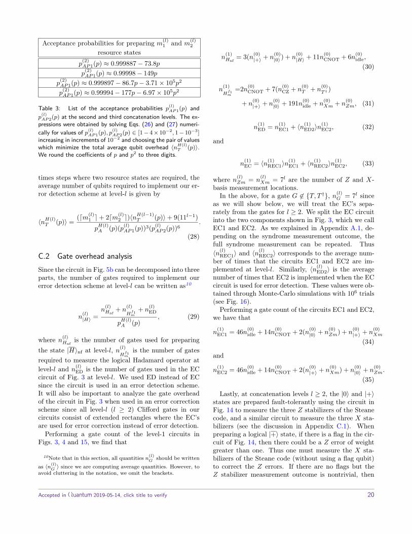
Acceptance probabilities for preparing m(l)1 and m
(l)2
resource statesp
(2)AP1(p) ≈ 0.999887− 73.8pp
(2)AP1(p) ≈ 0.99998− 149p
p(2)AP1(p) ≈ 0.999897− 86.7p− 3.71× 10⁵p2
p(2)AP1(p) ≈ 0.99994− 177p− 6.97× 10⁵p2
Table 3: List of the acceptance probabilities p(l)AP1(p) and
p(l)AP2(p) at the second and third concatenation levels. The ex-
pressions were obtained by solving Eqs. (26) and (27) numeri-cally for values of p(l)
AP1(p), p(l)AP2(p) ∈ [1− 4× 10⁻², 1− 10−3]
increasing in increments of 10−2 and choosing the pair of valueswhich minimize the total average qubit overhead 〈nH(l)
T (p)〉.We round the coefficients of p and p2 to three digits.
times steps where two resource states are required, theaverage number of qubits required to implement our er-ror detection scheme at level-l is given by
〈nH(l)T (p)〉 = (dm(l)
1 e+ 2dm(l)2 e)〈n
H(l−1)T (p)〉+ 9(11l−1)
pH(l)A (p)(p(l)
AP1(p))3(p(l)AP2(p))6
.
(28)
C.2 Gate overhead analysisSince the circuit in Fig. 5b can be decomposed into threeparts, the number of gates required to implement ourerror detection scheme at level-l can be written as10
n(l)|H〉 =
n(l)Hnf
+ n(l)Hf1m
+ n(l)ED
pH(l)A (p)
, (29)
where n(l)Hnf
is the number of gates used for preparingthe state |H〉nf at level-l, n(l)
Hf1m
is the number of gatesrequired to measure the logical Hadamard operator atlevel-l and n(l)
ED is the number of gates used in the ECcircuit of Fig. 3 at level-l. We used ED instead of ECsince the circuit is used in an error detection scheme.It will also be important to analyze the gate overheadof the circuit in Fig. 3 when used in an error correctionscheme since all level-l (l ≥ 2) Clifford gates in ourcircuits consist of extended rectangles where the EC’sare used for error correction instead of error detection.
Performing a gate count of the level-1 circuits inFigs. 3, 4 and 15, we find that
10Note that in this section, all quantities n(l)G should be written
as 〈n(l)G 〉 since we are computing average quantities. However, to
avoid cluttering in the notation, we omit the brackets.
n(1)Hnf
= 3(n(0)|+〉 + n
(0)|0〉) + n
(0)|H〉 + 11n(0)
CNOT + 6n(0)idle,
(30)
n(1)Hf1m
=2n(0)CNOT + 7(n(0)
CZ + n(0)T + n
(0)T † )
+ n(0)|+〉 + n
(0)|0〉 + 191n(0)
idle + n(0)Xm + n
(0)Zm, (31)
n(1)ED = n
(1)EC1 + 〈n(1)
ED2〉n(1)EC2, (32)
and
n(1)EC = 〈n(1)
REC1〉n(1)EC1 + 〈n(1)
REC2〉n(1)EC2, (33)
where n(l)Zm = n
(l)Xm = 7l are the number of Z and X-
basis measurement locations.In the above, for a gate G 6∈ {T, T †}, n(l)
G = 7l sinceas we will show below, we will treat the EC’s sepa-rately from the gates for l ≥ 2. We split the EC circuitinto the two components shown in Fig. 3, which we callEC1 and EC2. As we explained in Appendix A.1, de-pending on the syndrome measurement outcome, thefull syndrome measurement can be repeated. Thus〈n(l)
REC1〉 and 〈n(l)REC2〉 corresponds to the average num-
ber of times that the circuits EC1 and EC2 are im-plemented at level-l. Similarly, 〈n(l)
ED2〉 is the averagenumber of times that EC2 is implemented when the ECcircuit is used for error detection. These values were ob-tained through Monte-Carlo simulations with 106 trials(see Fig. 16).
Performing a gate count of the circuits EC1 and EC2,we have that
n(1)EC1 = 46n(0)
idle + 14n(0)CNOT + 2(n(0)
|0〉 + n(0)Zm) + n
(0)|+〉 + n
(0)Xm
(34)
and
n(1)EC2 = 46n(0)
idle + 14n(0)CNOT + 2(n(0)
|+〉 + n(0)Xm) + n
(0)|0〉 + n
(0)Zm.
(35)
Lastly, at concatenation levels l ≥ 2, the |0〉 and |+〉states are prepared fault-tolerantly using the circuit inFig. 14 to measure the three Z stabilizers of the Steanecode, and a similar circuit to measure the three X sta-bilizers (see the discussion in Appendix C.1). Whenpreparing a logical |+〉 state, if there is a flag in the cir-cuit of Fig. 14, then there could be a Z error of weightgreater than one. Thus one must measure the X sta-bilizers of the Steane code (without using a flag qubit)to correct the Z errors. If there are no flags but theZ stabilizer measurement outcome is nontrivial, then
Accepted in Quantum 2019-05-14, click title to verify 20

(a) (b)
(c) (d)
Figure 16: (a) Plot showing the values obtained for 〈n(l)REC1〉 and 〈n
(l)REC2〉 at the first three concatenation levels of the Steane code.
(b) Plots showing the values obtained for 〈n(l)XS0〉 and 〈n
(l)ZS0〉 when preparing the |0〉 state at the first three concatenation levels.
(c) Same as in (b) but for the |+〉 state. (d) Plot showing the values of 〈n(l)ED2〉 at the first three levels. All plots were obtained by
performing a Monte-Carlo simulation with 106 trials.
Accepted in Quantum 2019-05-14, click title to verify 21

Figure 17: Circuit illustrating shared EC units between twological CNOT gates and an idle qubit location. It is importantnot to double-count overlapping EC’s when computing the gateoverhead at concatenation levels l ≥ 2.
one must repeat the Z syndrome measurement withoutthe flag qubit. A similar analysis holds for preparinga logical |0〉 state. Hence, as in Eqs. (32) and (33),we must also take into account the average number oftimes the non-flagged X and Z stabilizers are measuredwhen counting the number of gates required to preparelevel-l |0〉 and |+〉 states. The averages are obtained byperforming a Monte-Carlo simulation (see Fig. 16). Inwhat follows we define n(l)
XS and n(l)ZS to be the number
of locations in the level-l X and Z stabilizer measure-ment circuit without the flag qubits and 〈n(l)
XS+/0〉 and〈n(l)ZS+/0〉 to be the average number of times these cir-
cuits are used when preparing a level-l | + /0〉 state.Performing the level-1 gate count, we have that
n(1)|+〉 =73n(0)
idle + 15n(0)CNOT + 8n(0)
|+〉 + 3(n(0)|0〉 + n
(0)Zm) + n
(0)Xm
+ 〈n(1)ZS+〉n
(1)ZS + 〈n(1)
XS+〉n(1)XS , (36)
and
n(1)|0〉 =73n(0)
idle + 15n(0)CNOT + 8n(0)
|0〉 + 3(n(0)|+〉 + n
(0)Xm) + n
(0)Zm
+ 〈n(1)ZS0〉n
(1)ZS + 〈n(1)
XS0〉n(1)XS , (37)
with
n(1)ZS = 48n(0)
idle + 11n(0)CNOT + 3(n(0)
|0〉 + n(0)Zm), (38)
and
n(1)XS = 48n(0)
idle + 11n(0)CNOT + 3(n(0)
|+〉 + n(0)Xm). (39)
We now have all the tools to obtain the gate over-head at arbitrary concatenation levels. Recall that atconcatenation levels l ≥ 2, all physical gates G in thecircuits of Fig. 5b are represented by extended rect-angles, which consists of the logical gate G precededand followed by EC units (in our case, the circuit inFig. 3). More details on extended rectangles can befound in [30]. When computing the gate overhead ofthe error detection scheme (Eq. (29) with l ≥ 2), we
must be careful not to double-count overlapping EC’ssince consecutive gates will share an EC (see Fig. 17 foran example).
Lastly, for l ≥ 2, the T and T † gates are implementedas shown in Fig. 1. We thus see that the overhead forthese gates can be computed recursively using
n(l)T = n
(l)T † = n
(l−1)|H〉 + 3n(l−1)
EC + 4(7l). (40)
With the above considerations and using Eq. (40),the gate overhead can be computed recursively usingthe following relations. First, the recursive relations forthe EC unit are given by
n(l)EC = 〈n(l)
REC1〉n(l)EC1 + 〈n(1)
REC2〉n(l)EC2, (41)
where
n(l)EC1 = 2n(l−1)
|0〉 + n(l−1)|+〉 + 73n(l−1)
EC + 63(7l), (42)
and
n(l)EC2 = 2n(l−1)
|+〉 + n(l−1)|0〉 + 66n(l−1)
EC + 63(7l). (43)
Next, the recursive relations for the |0〉 and |+〉 statesare
n(l)|0〉 = 8n(l−1)
|0〉 + 3n(l−1)|+〉 + 100n(l−1)
EC + 92(7l)
+ 〈n(l)ZS0〉n
(l)ZS + 〈n(l)
XS0〉n(l)XS , (44)
n(l)|+〉 = 8n(l−1)
|+〉 + 3n(l−1)|0〉 + 100n(l−1)
EC + 92(7l)
+ 〈n(l)ZS+〉n
(l)ZS + 〈n(l)
XS+〉n(l)XS , (45)
where
n(l)ZS = 3n(l−1)
|0〉 + 62(7l) + 70n(l−1)EC , (46)
and
n(l)XS = 3n(l−1)
|+〉 + 62(7l) + 70n(l−1)EC . (47)
Using Eqs. (41) to (47) and the results in Fig. 16, wecan compute the following expressions
n(l)Hnf
= 3(n(l−1)|+〉 + n
(l−1)|0〉 ) + n
(l−1)|H〉 + 28n(l−1)
EC + 17(7l−1),(48)
n(l)Hf1m
= n(l−1)|+〉 + n
(l−1)|0〉 + 202(7l) + 14n(l)
T + 129n(l−1)EC ,
(49)
and
n(l)ED = n
(l)EC1 + 〈n(l)
ED2〉n(l)EC2. (50)
Note that n0EC = 0 and n(0)
T = n(0)T † = n
(0)|H〉 = n
(0)|0〉 =
n(0)|+〉 = 1.
Accepted in Quantum 2019-05-14, click title to verify 22

D Overhead analysis for the MEKschemeIn this section we provide a detailed description of thequbit and gate overhead analysis required to implementthe MEK scheme.
D.1 Qubit overhead analysisWe first compute the overhead cost of teleporting aphysical |H〉 state to a level-2 |H〉 state and then per-forming one round of level-2 MEK.
Let n(T )qij be the qubit overhead cost of a level-i |H〉
state teleported to a level-j |H〉 state. From the tele-portation of Fig. 13, a level-2 |0〉 and |+〉 state must beprepared, each requiring 112 qubits. We assume thatthese qubits can be reused when performing the logicalgates and EC’s that follow (since an EC requires only 10qubits). Including the qubit for the physical |H〉 state,we have
n(T )q02 = 2(112) + 1 = 243. (51)
Next we define n(l)qMEK to be the qubit overhead cost
associated with performing a level-l round of MEK. Wealso define a(l)
MEK to be the probability that a pair oflevel-l |H〉 states are accepted in a level-l round ofMEK. When implementing a level-l MEK circuit, wemust prepare two level-l |+〉 states and one level-l |0〉state. As was explained in Appendix C.1, we requiretwo additional level-l |H〉 states in order to perform theCH gates. Thus the level-2 MEK circuit qubit over-head with level-2 |H〉 states teleported from physical|H〉 states is given by
n(2)qMEK(p) = 3(112) + 4(243)
a(2)MEK(p)
= 1335a
(2)MEK(p)
. (52)
Since the MEK circuit produces two distilled |H〉states, when we compare the qubit overhead cost to our|H〉 state preparation error detection scheme, we willdivide Eq. (52) by two. We note that several additionaloptimizations are possible. For instance, some of thequbits used for teleporting the |H〉 states that are usedto perform the CH gates could be reused. Addition-ally, the extra qubits used for preparing the level-l |0〉and |+〉 states for the MEK circuit could also be reusedin various parts of the protocol. However these addi-tional optimizations are likely to strongly depend onthe particular architecture that is being used and theirassociated constraints. Therefore, to be as general aspossible, these will be omitted.
We now consider the overhead cost for performinga round of level-3 MEK. We first teleport the distilledlevel-2 |H〉 states to level-3 |H〉 states. We have that
n(T )q23(p) = 2(113) +
n(2)qMEK(p)
2= 2662 + 1335
2a(2)MEK(p)
. (53)
Using the level-3 |H〉 states, the qubit overhead for alevel-3 MEK simulation is given by
n(3)qMEK(p) =
3(113) + 4n(T )q23(p)
a(3)MEK(p)
, (54)
where we will divide Eq. (54) by two when comparingwith the qubit overhead of our error detection scheme.
For the case when a level-2 |H〉 state is prepared usingour error detection scheme, we must first teleport thelevel-2 |H〉 state to a level-3 |H〉 state. Defining n(T )
2ED3to be the overhead cost for the teleportation step, wehave
n(T )2ED3(p) = 2(113) + 〈nH(2)
T (p)〉, (55)
where 〈nH(2)T (p)〉 is obtained from Eq. (28). Hence the
overhead cost for performing a round of level-3 MEK isgiven by
n(3)qMEKED(p) = 3(113) + 4n(T )
2ED3(p)2a(3)
MEKED(p), (56)
where a(3)MEKED is the acceptance probability for the
level-3 MEK scheme when the level-2 |H〉 states (tele-ported to level-3) were obtained from our error detec-tion scheme.
D.2 Gate overhead analysisWe now consider the gate overhead analysis for the var-ious rounds of MEK considered in Appendix D.1.
Let n(T )gij be the qubit overhead cost of a level-i |H〉
state teleported to a level-j |H〉 state. Two EC’s mustbe performed after applying the logical CNOT gate. Wemust also take into account the gate cost for the decod-ing circuit. The decoding circuit requires the prepara-tion of four |+〉 states and three |0〉 states. There areeight CNOT gates and the circuit requires a total of 16EC’s. Let n(D)
ij be the number of gates in the decodingcircuit for level-i to level-j teleportation scheme. Wehave that
Accepted in Quantum 2019-05-14, click title to verify 23

n(D)02 = 4(n(2)
|+〉 + n(1)|+〉) + 3(n(2)
|0〉 + n(1)|0〉)
+ 16(n(1)EC + n
(2)EC) + 8(72 + 7), (57)
where n(l)EC, n
(l)|0〉 and n
(l)|+〉 are given by Eqs. (41), (44)
and (45). We then have
n(T )gij = n
(2)|+〉 + n
(2)|0〉 + 2n(2)
EC + n(D)02 + 72 + 4. (58)
The last term in Eq. (58) is due to the four physicaloperations of the decoding circuit.
Next we compute the gate overhead of the level-2MEK scheme. The circuit has 48 logical gates, 177 EC’sand requires the preparation of two level-2 |+〉 statesand one level-2 |0〉 state. Defining n
(l)gMEK to be the
gate overhead of a level-l MEK circuit, we have
n(2)gMEK =
4n(T )g02 + 2n(2)
|+〉 + n(2)|0〉 + 48(72) + 177n(2)
EC
a(2)MEK(p)
.
(59)
Again when comparing the gate overhead of a level-2MEK circuit to the gate overhead required to preparea level-2 |H〉 state using our error detection scheme, wewill divide Eq. (59) since an MEK circuit produces twodistilled |H〉 states.
Following the same steps that lead to Eq. (59), itis straightforward to compute the gate overhead for alevel-3 MEK circuit. Using
n(D)23 = 4n(3)
|+〉 + 3n(3)|0〉 + 16n(3)
EC + 8(73), (60)
and
n(T )g23 = n
(3)|+〉 + n
(3)|0〉 + 2n(3)
EC
+ 3n(2)EC + 73 + 72 + n
(D)23 +
n(2)gMEK
2 , (61)
we get
n(3)gMEK =
4n(T )g23 + 2n(3)
|+〉 + n(3)|0〉 + 48(73) + 177n(3)
EC
a(3)MEK(p)
.
(62)
The gate overhead for a level-3 MEK scheme where alevel-2 |H〉 state was prepared from our error detectionscheme is obtained as follows. First we compute thegate overhead to teleport the level-2 |H〉 state to a level-3 |H〉 state. It is given by
n(T )g23ED(p) = n
(2)|H〉 + n
(3)|+〉 + n
(3)|0〉
+ 2n(3)EC + 3n(2)
EC + 73 + 72 + n(D)23 , (63)
where n(2)|H〉 is obtained from Eq. (29). Using Eq. (63)
we obtain
n(3)gMEKED =
4n(T )g23ED(p) + 2n(3)
|+〉 + n(3)|0〉 + 48(73) + 177n(3)
EC
a(3)MEKED(p)
,
(64)
where a(3)MEKED is the acceptance probability of the level-
3 MEK circuit when the level-2 |H〉 states (teleported tolevel-3) are obtained from our error detection scheme.
E State vector simulationsHere we describe how we simulate each |H〉 state prepa-ration and MEK magic state distillation circuit. Acommon method for simulating fault-tolerant error-correction is to apply the Gottesman-Knill theoremto track how Pauli errors propagate through stabilizercircuits. However, unlike error-correction, circuits formagic state preparation and distillation contain non-Clifford gates that map Pauli errors outside the Pauligroup, complicating the analysis. Since all of the cir-cuits we consider act on relatively few qubits, we use theQiskit state vector simulation [45] to accurately trackerror propagation through non-Clifford gates.
Each gate, preparation, idle and measurement loca-tion is subject to Pauli channel errors whose probabil-ities are functions of the physical error rate p that aredetermined by the noise model at level-1 and the log-ical error probabilities of fault-tolerant gates at level-2and above (see Section 2). For each value of p, we runbetween 106 and 108 Monte-Carlo samples, where eachsample draws an error at each fault location. The cir-cuits are composed with an ideal decoder so that theoutput state is one or two physical qubits for statepreparation or distillation, respectively. The output foreach sample i is a pure state vector |ψi〉 and a measure-ment record mi on which we post-select.
For simulations of |H〉 state preparation, we computeoverlaps 〈ψi|P |ψi〉 for each Pauli P to determine thelogical error class, since in this case the logical error isalways of this form after ideal decoding. However, forthe MEK distillation protocol there are additional fail-ure modes. For example, the two output qubits can bein a maximally entangled state. This can be seen byplacing Y errors on the fourth and seventh |H〉 states,which corresponds to failures of the first T gate and
Accepted in Quantum 2019-05-14, click title to verify 24

third T † gate. Therefore, we solve for Pauli channelparameters using an estimate of the output density ma-trix ρ ≈
∑i |ψi〉〈ψi|. First, we compute the reduced
state ρ = Tr2ρ of one output qubit. Next, we modelthe output state as a Pauli channel applied to the stateρH = |H〉〈H|,
E(ρH) = (1− px − pz)ρH + pxXρHX + pzZρHZ
(65)
= 12√
2
(1 +√
2− 2px 1− 2pz1− 2pz −1 +
√2 + 2px
).
(66)
For the parameter ranges we considered, we can solvefor the Pauli channel parameters in terms of the matrixelements of ρ,
px = 1 +√
2− 2√
2ρ00
2 (67)
pz = 1− 2√
2ρ01
2 . (68)
We substitute these parameters back into the modeland verify the density matrices are equal to machineprecision.
The logical error probabilities and rejection probabil-ities are fit to functions of the physical error p. Statepreparation results are summarized in Table 4 and dis-tillation results in Table 5. For the second round ofdistillation, the O(p4) contribution to the logical erroris too small to observe with 108 Monte-Carlo trials, sowe do two such simulations. The first case uses ideal |H〉states and noisy stabilizer operations, while the secondcase uses noisy |H〉 states and ideal stabilizer opera-tions. We simulate the second case at higher physicalerror rates to estimate the coefficient of the O(p4) term.Finally, we approximate the logical error rate and ac-ceptance probability of the noisy circuit as a piecewisefunction (see the caption of Table 5).
Accepted in Quantum 2019-05-14, click title to verify 25

Concatenation Pr[accept] Pr[mal(l)E |G, p]l = 1 (1− p)75 (9.95, 4.41, 7.87)p2
l = 2 (1− 3000p2)200 (1.26, 0.0627, 1.09)× 109p4
l = 2∗ 1− 3.67p− 2.67× 10³p2 (5.14, 0.33, 2.26)× 104p4
l = 3 1− 84.3p+ 1.60× 10⁶p2 − 9.41× 10⁹p3 (1.23, 0.0555, 1.16)× 1024p8
l = 3∗ 1− 84.3p+ 1.60× 10⁶p2 − 9.41× 10⁹p3 (1.24, 0.0683, 1.17)× 1024p8
Table 4: State vector simulation results for |H〉 state preparation circuits using error-detection. The error probabilities (px, py, pz)are given as functions of p for each error type E ∈ {X,Y, Z}. The entires marked with (∗) use error-detection circuits for level-1stabilizer operations (only in the |H〉 state preparation circuit). The acceptance probabilities are for the level-l circuit and do notinclude rejections at lower levels of concatenation. The expressions are all approximations computed using a standard non-linearfitting method, and coefficients are rounded to three digits. The level-3 expressions are valid for p ≤ 4 × 10⁻⁴. We notice thatboth level-3 error polynomials are similar. This is due to the fact that errors arising from the level-2 |H〉 states have a much smallercontribution to the overall logical error rate compared to the Clifford operations.
Circuit Pr[accept] Pr[mal(l)E |G, p]hybrid, l = 3 1− 3.45× 10²⁰p6 (0.812, 1.68)× 1026p8
round-1, l = 2 1− 32.2p+ 2.24× 10⁴p2 − 2.37× 10⁹p3 (150, 152)p2 + (1.01, 2.00)× 1011p4
round-2, l = 3, ideal |H〉 1− 6.50× 1027p8 (1.43, 2.43)× 1026p8
round-2, l = 3, ideal stabilizer∗ 1− 1.47× 10³p2 (1.97, 1.84)× 105p4
round-3, l = 3 1− 8.00× 1027p8 (2.00, 3.04)× 1026p8
Table 5: State vector simulation results for Meier-Eastin-Knill distillation circuits. The error probabilities (px, pz) are given asfunctions of p for each error type E ∈ {X,Z}. The expressions are all approximations computed using a standard non-linear fittingmethod, and coefficients are rounded to three digits. The expressions are valid for p ≤ 2 × 10⁻⁴, except for (∗) which is validfor p ≤ 5 × 10⁻³. For round-2, we combine the two results in the table into the following optimistic piecewise approximation:Pr[accept] ≈ 1−max(1.47× 10³p2, 6.50× 1027p8) and Pr[mal(l)E |G, p] ≈ (1.97, 1.84)× 105p4 + (1.43, 2.43)× 1026p8.
Accepted in Quantum 2019-05-14, click title to verify 26