Fault-Tolerant Coarse-Grained Data-flow...
135
Fault-Tolerant Coarse-Grained Data-Flow Execution Dissertation zur Erlangung des akademischen Grades eines Doktors der Naturwissenschaften der Fakult¨ at f¨ ur Angewandte Informatik der Universit¨ at Augsburg eingereicht von Dipl.-Inf. Sebastian Weis
Transcript of Fault-Tolerant Coarse-Grained Data-flow...
Fault-Tolerant Coarse-GrainedData-Flow Execution
Dissertationzur Erlangung des akademischen Grades eines
Doktors der Naturwissenschaftender Fakultat fur Angewandte Informatik
der Universitat Augsburg
eingereicht vonDipl.-Inf. Sebastian Weis

Fault-Tolerant Coarse-Grained Data-Flow ExecutionSebastian Weis
Erstgutachter: Prof. Dr. Theo UngererZweitgutachter: Prof. Dr.-Ing. Rudi Knorr
Tag der mundlichen Prufung: 26. November 2015

Kurzfassung
Das Fortschreiten der Halbleitertechnologie und die damit verbundene Steigerung derTransistorintegrationsdichte hat die Entwicklung immer leistungsfahigerer Multicore-Prozessoren maßgeblich vorangetrieben. Bedingt durch die stetige Verkleinerung derStrukturgroßen in Richtung der physikalischen Grenzen steigen aber auch die Wahrschein-lichkeiten von transienten, intermittierenden und permanenten Fehlern in den Prozessor-Chips. Diese Entwicklung macht effiziente Fehlertoleranzmechanismen in Zukunft auchfur universale Multicore-Prozessoren notwendig. Allerdings ist die redundante Program-mausfuhrung, wie sie in sicherheitskritischen und hochverfugbaren Lockstep-Systemenseit langer Zeit verwendet wird, fur gegenwartige Universalprozessoren aufwendig, daAnderungen an der Mikroarchitektur benotigt werden, welche die Skalierbarkeit der Syste-me einschranken konnen. Zusatzlich wird die Verwendung moderner Energiesparmaßnah-men und die Ausfuhrung paralleler Anwendungen durch die Lockstep-Implementierungerschwert.
Die vorliegende Dissertation beschreibt die Integration von flexiblen Fehlertoleranz-mechanismen in ein grobkorniges Datenflussausfuhrungsmodell, welche insbesonderedie skalierbare Ausfuhrung von parallelen Anwendungen in einem Multicore-Prozessorerhalten sollen. Zur Fehlererkennung wird die entkoppelte redundante Ausfuhrung vonDatenfluss-Threads (Double Execution) vorgestellt, welche die Korrektur von Fehlerndurch Thread-Neustarts unterstutzt. Dabei werden notwendige Anpassungen am Da-tenflussausfuhrungsmodell und der Hardware-Architektur sowie Techniken zur Einga-bereplikation, zur Thread-Synchronisierung und zum Ausgabevergleich beschrieben.Basierend auf der redundanten Ausfuhrung von Datenfluss-Threads wird eine Methodezur Diagnose von permanenten und intermittierenden Fehlern vorgeschlagen, die imFehlerfall eine Anpassung des Systems ermoglicht. Um die Parallelitat der redundan-ten Datenflussausfuhrung zu erhohen, wird die optimistische redundante Ausfuhrungvon Datenfluss-Threads (Optimistic Double Execution) vorgestellt, welche nachfolgendeDatenfluss-Threads spekulativ starten kann, noch bevor die Korrektheit der Berechnungs-ergebnisse verifiziert werden konnte. Um die Fehlerkorrektur auch fur die optimistischeredundante Ausfuhrung zu ermoglichen, wird ein datenflussbasierter globaler Wiederher-stellungsmechanismus vorgestellt.
Die datenflussbasierten Fehlertoleranzmechanismen wurden mit Hilfe des Open-Source-Multicore-Simulators COTSon untersucht. Dabei zeigte sich, dass die redundante Thread-Ausfuhrung nur geringe zusatzliche Laufzeitkosten gegenuber einer optimalen Lockstep-Maschine aufweist und in bestimmten Fallen sogar Laufzeitvorteile bieten kann. Im Fallevon permanenten Fehlern in den Prozessorkernen zeigte sich, dass die Ausfuhrungsge-schwindigkeit des Systems schrittweise angepasst werden kann. Des Weiteren konnentransiente Fehler durch den Neustart von Datenfluss-Threads mit geringen Kostenkorrigiert werden. Fur die optimistische redundante Ausfuhrung zeigte sich, dass Anwen-dungen mit geringer Parallelitat ungenutzte Systemressourcen zur Beschleunigung derredundanten Ausfuhrung nutzen konnen.

Abstract
The progress of the semiconductor technology and the resulting increase of the tran-sistor integration density has driven the development of ever more powerful multi-coreprocessors. The reduction of the feature sizes in the direction of the physical limitsincreases the probabilities of transient, intermittent, and permanent faults in the chipsand demands efficient fault-tolerance mechanisms also for future general-purpose multi-core processors. However, the use of redundant execution mechanisms, as they havebeen implemented in safety-critical and high-availability lockstep systems for a longtime, can be expensive in general-purpose processors, since they require changes to themicroarchitecture, which can limit the scalability of the systems. Additionally, lockstepexecution complicates the use of modern power management mechanisms as well as theexecution of parallel applications.
This thesis describes the integration of flexible fault-tolerance mechanisms in a coarse-grained data-flow execution model, which are able to preserve the scalable executionof parallel applications in a multi-core system. For fault detection, we present doubleexecution, the decoupled redundant execution of data-flow threads, which supports faultrecovery by the restart of data-flow threads. In this context, necessary adaptions tothe data-flow execution model and the hardware architecture as well as techniques forinput replication, thread synchronisation, and output comparison are described. Basedon the redundant thread execution, a method to diagnose permanent and intermittentfaults is developed, which enables the adaption of the system in case of these faults.To further increase the parallelism of double execution, optimistic double execution isproposed, which is able to speculatively start subsequent data-flow threads before resultverification. In order to recover from errors detected with optimistic double execution, adata-flow based global checkpointing mechanism is presented.
The data-flow based fault-tolerance mechanisms were studied with the open-sourcemulti-core simulator COTSon. The evaluation shows that double execution introducessmall run time overhead compared to an ideal lockstep machine and can even achieve aspeedup in certain cases. Furthermore, the execution speed of double execution can begradually reduced, when permanent faults in the processing elements occur. In case oftransient faults, the restart of data-flow threads has only a small impact on the executionspeed, while optimistic double execution can exploit underutilised system resources tospeed up the redundant execution of applications with low parallelism.


Danksagung
An dieser Stelle mochte ich mich bei den Personen bedanken, ohne deren Unterstutzungdiese Dissertation nicht hatte geschrieben werden konnen.
Zuallererst bedanke mich bei meinem Doktorvater, Herrn Prof. Dr. Theo Ungerer,dass er mir die Moglichkeit geben hat, diese Dissertation im Rahmen des TerafluxProjekts verfassen zu konnen. In jeder Phase meines Promotionsvorhabens stand ermir mit konstruktiver Kritik und zahlreichen Verbesserungsvorschlagen zur Seite. BeiHerrn Prof. Dr.-Ing. Rudi Knorr bedanke ich mich fur die Zweitbegutachtung dieserDissertation. Herrn Prof. Dr. Bernhard Bauer danke ich, dass er sich als Prufer zurVerfugung gestellt hat.
Weiterhin danke ich allen Mitarbeitern des Lehrstuhls, mit denen ich in den letztenJahren erfolgreich an den verschiedensten Projekten, Forschungsantragen und Lehrver-anstaltung zusammenarbeiten durfte. Mein besonderer Dank gilt den Kollegen StefanMetzlaff, Florian Haas, Jorg Mische und Arne Garbade fur die unzahligen wissen-schaftlichen und nicht-wissenschaftlichen Diskussionen, die wesentlich zu dieser Arbeitbeigetragen haben.
Bei meiner Familie, insbesondere meiner Frau Verena, bedanke ich mich fur die großeGeduld und die grenzenlose Unterstutzung.
Finally, I’d also like to thank Prof. Dr. Roberto Giorgi from the University of Sienafor his great hospitality during my stays in Siena.
Sebastian Weis


Table of Contents
List of Abbreviations 13
1 Introduction 151.1 Main Contributions . . . . . . . . . . . . . . . . . . . . . . . . . . . . . . 16
1.2 Structure . . . . . . . . . . . . . . . . . . . . . . . . . . . . . . . . . . . 17
1.3 Publications . . . . . . . . . . . . . . . . . . . . . . . . . . . . . . . . . . 17
2 Background 192.1 Faults in Computer Systems . . . . . . . . . . . . . . . . . . . . . . . . . 19
2.1.1 Manifestation of Faults . . . . . . . . . . . . . . . . . . . . . . . 19
2.1.2 Duration and Sources of Faults . . . . . . . . . . . . . . . . . . . 20
2.1.3 Increasing Fault Rates in Future Systems . . . . . . . . . . . . . 21
2.2 Fault-Tolerant Computer Systems . . . . . . . . . . . . . . . . . . . . . 22
2.2.1 Information Redundancy . . . . . . . . . . . . . . . . . . . . . . 22
2.2.2 Spatial Redundancy . . . . . . . . . . . . . . . . . . . . . . . . . 23
2.2.3 Temporal Redundancy . . . . . . . . . . . . . . . . . . . . . . . . 23
2.3 Redundant Execution . . . . . . . . . . . . . . . . . . . . . . . . . . . . 23
2.3.1 Tightly-Coupled Redundant Execution . . . . . . . . . . . . . . . 24
2.3.2 Loosely-Coupled Redundant Execution . . . . . . . . . . . . . . . 24
2.4 Recovery . . . . . . . . . . . . . . . . . . . . . . . . . . . . . . . . . . . . 27
2.4.1 Terminology . . . . . . . . . . . . . . . . . . . . . . . . . . . . . 27
2.4.2 BER in Shared-Memory Processors . . . . . . . . . . . . . . . . . 27
2.4.3 Relation between Fault Detection and Checkpointing . . . . . . . 28
2.4.4 Fault Diagnosis and Adaption for Permanent/Intermittent Faults 29
2.5 Combining Fault Tolerance and Data-flow Execution . . . . . . . . . . . 30
2.5.1 The Data-flow Execution Principle . . . . . . . . . . . . . . . . . 30
2.5.2 Hybrid Data-flow/Von Neumann Execution . . . . . . . . . . . . 31
2.5.3 Combining Fault Tolerance and Data-flow Execution . . . . . . . 31
2.6 Summary . . . . . . . . . . . . . . . . . . . . . . . . . . . . . . . . . . . 32
3 Related Work 333.1 Redundant Execution Mechanisms . . . . . . . . . . . . . . . . . . . . . 33
3.1.1 Lockstep Redundancy . . . . . . . . . . . . . . . . . . . . . . . . 33
3.1.2 Microarchitectural Redundancy . . . . . . . . . . . . . . . . . . . 34
3.1.3 Thread-Level Redundancy in SMT Architectures . . . . . . . . . 35
3.1.4 Thread-Level Redundancy in Multi-Core Architectures . . . . . . 37
3.2 Backward Error Recovery in Shared-Memory Multi-Cores . . . . . . . . 38
3.3 Fault-Tolerant Data-Flow Execution . . . . . . . . . . . . . . . . . . . . 39
9

3.4 Tolerating Permanent Faults . . . . . . . . . . . . . . . . . . . . . . . . 41
3.4.1 Deactivation and Reconfiguration of Cores . . . . . . . . . . . . . 41
3.4.2 Deactivation and Reconfiguration of Microarchitectural Components 41
3.5 Summary . . . . . . . . . . . . . . . . . . . . . . . . . . . . . . . . . . . 42
4 Baseline Execution Model and Architecture 454.1 A Coarse-Grained Data-Flow Execution Model . . . . . . . . . . . . . . 45
4.2 Baseline Hardware Architecture . . . . . . . . . . . . . . . . . . . . . . . 47
4.3 Architectural Support for Data-Flow Execution . . . . . . . . . . . . . . 48
4.3.1 The T*-Instruction Set Extension . . . . . . . . . . . . . . . . . 48
4.3.2 Thread Scheduling Unit . . . . . . . . . . . . . . . . . . . . . . . 49
4.4 Physical Memory Organisation . . . . . . . . . . . . . . . . . . . . . . . 50
4.5 Summary . . . . . . . . . . . . . . . . . . . . . . . . . . . . . . . . . . . 51
5 Fault-Tolerant Data-Flow Execution 535.1 Overview of the Data-Flow Based Fault-Tolerance Mechanisms . . . . . 53
5.1.1 Fault-Tolerant Coarse-Grained Data-Flow Execution . . . . . . . 53
5.1.2 Faults Covered by the Data-flow Based Fault-Tolerance Mechanisms 55
5.2 Extended Fault-Tolerant Hardware Architecture . . . . . . . . . . . . . 56
5.3 Double Execution of Data-Flow Threads . . . . . . . . . . . . . . . . . . 57
5.3.1 Double Execution Overview . . . . . . . . . . . . . . . . . . . . . 57
5.3.2 Sphere of Replication of Double Execution . . . . . . . . . . . . . 59
5.3.3 Input Replication . . . . . . . . . . . . . . . . . . . . . . . . . . . 60
5.3.4 Synchronisation and Output Comparison . . . . . . . . . . . . . 62
5.3.5 Asynchronous Thread Execution . . . . . . . . . . . . . . . . . . 63
5.3.6 Influence of Double Execution on the Execution Time . . . . . . 64
5.4 Restart of Data-Flow Threads . . . . . . . . . . . . . . . . . . . . . . . . 64
5.4.1 Speculative Thread Creation . . . . . . . . . . . . . . . . . . . . 65
5.5 Data-Flow Runtime Enhancements . . . . . . . . . . . . . . . . . . . . . 65
5.5.1 Extended Continuation for Double Execution . . . . . . . . . . . 65
5.5.2 ID Table . . . . . . . . . . . . . . . . . . . . . . . . . . . . . . . . 66
5.6 Fault Diagnosis and Periodic Tests . . . . . . . . . . . . . . . . . . . . . 67
5.6.1 Fault Diagnosis . . . . . . . . . . . . . . . . . . . . . . . . . . . . 68
5.6.2 Periodic Testing . . . . . . . . . . . . . . . . . . . . . . . . . . . 68
5.7 Summary . . . . . . . . . . . . . . . . . . . . . . . . . . . . . . . . . . . 70
6 Optimistic Double Execution and Global Checkpointing 716.1 Optimistic Double Execution . . . . . . . . . . . . . . . . . . . . . . . . 71
6.1.1 Increasing Parallelism by Optimistic Thread Commit . . . . . . . 71
6.1.2 Run time Behaviour of Optimistic Double Execution . . . . . . . 73
6.1.3 Input Replication . . . . . . . . . . . . . . . . . . . . . . . . . . . 73
6.1.4 Output Comparison . . . . . . . . . . . . . . . . . . . . . . . . . 75
6.2 Data-flow based Global Checkpointing . . . . . . . . . . . . . . . . . . . 76
6.2.1 Establishing a Checkpoint . . . . . . . . . . . . . . . . . . . . . . 76
6.2.2 Logging of Memory Accesses . . . . . . . . . . . . . . . . . . . . 77
6.2.3 Checkpointing Overhead . . . . . . . . . . . . . . . . . . . . . . . 77
6.2.4 Overlapping of Checkpoint Verification and Data-Flow Execution 78

6.2.5 Fault Diagnosis and Adaption for Optimistic Double Executionand Global Checkpointing . . . . . . . . . . . . . . . . . . . . . . 78
6.3 Summary . . . . . . . . . . . . . . . . . . . . . . . . . . . . . . . . . . . 78
7 Evaluation 817.1 Simulation Methodology . . . . . . . . . . . . . . . . . . . . . . . . . . . 81
7.1.1 Simulator Framework . . . . . . . . . . . . . . . . . . . . . . . . 817.1.2 Baseline Machine Configuration . . . . . . . . . . . . . . . . . . . 817.1.3 Lockstep Machine Configurations . . . . . . . . . . . . . . . . . . 827.1.4 Fault Injection . . . . . . . . . . . . . . . . . . . . . . . . . . . . 837.1.5 Benchmarks . . . . . . . . . . . . . . . . . . . . . . . . . . . . . . 84
7.2 Double Execution . . . . . . . . . . . . . . . . . . . . . . . . . . . . . . . 877.2.1 Execution Overhead of Double Execution . . . . . . . . . . . . . 877.2.2 Scalability . . . . . . . . . . . . . . . . . . . . . . . . . . . . . . . 907.2.3 Commit Slack . . . . . . . . . . . . . . . . . . . . . . . . . . . . . 917.2.4 Graceful Degradation under Permanent Faults . . . . . . . . . . 937.2.5 Execution Overhead under Transient Faults . . . . . . . . . . . . 98
7.3 Optimistic Double Execution . . . . . . . . . . . . . . . . . . . . . . . . 997.3.1 Execution Overhead without Checkpoints . . . . . . . . . . . . . 1007.3.2 Scalability . . . . . . . . . . . . . . . . . . . . . . . . . . . . . . . 1027.3.3 Execution Overhead with Checkpoints . . . . . . . . . . . . . . . 1037.3.4 Commit Slack . . . . . . . . . . . . . . . . . . . . . . . . . . . . . 1067.3.5 Log Size of Global Checkpoints . . . . . . . . . . . . . . . . . . . 1087.3.6 Graceful Degradation under Permanent Faults . . . . . . . . . . 1097.3.7 Execution under Transient Faults . . . . . . . . . . . . . . . . . . 113
7.4 Summary . . . . . . . . . . . . . . . . . . . . . . . . . . . . . . . . . . . 115
8 Summary and Future Work 1178.1 Summary . . . . . . . . . . . . . . . . . . . . . . . . . . . . . . . . . . . 1178.2 Future Work . . . . . . . . . . . . . . . . . . . . . . . . . . . . . . . . . 119
Bibliography 121
List of Figures 131
List of Tables 133
List of Algorithms 135


List of Abbreviations
ALAB Active Load Address Buffer
CARER Cache-Aided Rollback Recovery
CB Comparison Buffer
CLB Checkpoint Log Buffer
CRTR Chiplevel Redundantly Threaded Multiprocessor with Recovery
DCC Dynamic Core Coupling
DE Double Execution
DMR Dual Modular Redundancy
DRMT Data-flow Scheduled Redundant Multi-Threading
DVFS Dynamic Voltage and Frequency Scaling
FDU Fault Detection Unit
HTM Hardware Transactional Memory
LBRA Log-based Redundant Architecture
LVQ Load Value Queue
ODE Optimistic Double Execution
PU Processor Unit
RQ Ready Queue
SDF Scheduled Data-Flow
SMT Simultaneous Multithreading
SRT Simultaneous Redundant Threading
SRTR Simultaneous Redundant Threading with Recovery
TF Thread Frame
TLP Thread-Level Parallelism
TLS Thread-Local Storage
TMR Triple Modular Redundancy
TPL Thread-To-PE-List
13

TQ Thread Queue
TSU Thread Scheduling Unit

1Introduction
Current microprocessor devices, like Nvidia’s Fermi architecture [Wittenbrink et al., 2011]or Intel’s Haswell [Hammarlund et al., 2014] microarchitecture incorporate several Billiontransistors1 and it is expected that the ongoing improvements of the semiconductorfabrication technology will let the number of transistors per chip further increase [ITRS,2013]. While the ongoing device scaling provides opportunities for computer architectsto build even more parallel and powerful computing devices, the shrinking feature sizesof future chips also increases the probability of transient, intermittent, and permanentfaults [Constantinescu, 2003; Srinivasan et al., 2004; Borkar, 2005]. This means thatexternal and internal influences on the chip, like voltage fluctuation, cosmic radiation,thermal cycling, variability in the manufacturing process, or silicon wearout, will lead toincreasing transient, permanent, and intermittent fault rates in future semiconductordevices [Mukherjee, 2008; Constantinescu, 2003; Borkar, 2005]. Additionally, the in-creasing gate leakage of future microprocessors raises the cost for burn-in testing of thedevices [Borkar, 2005]. It can be prospected that hardware faults in present multi-coreand future many-core systems may become unavoidable and fault-tolerance mechanismsmust be also considered for general-purpose multi-core processors.
While fault-tolerance mechanisms have a long tradition in safety-critical [Yeh, 1996]and high-availability computer systems [Siewiorek et al., 1998], the architecture of general-purpose microprocessors is much stronger influenced by economical constraints. Thismeans that future multi-core processors will require fault-tolerance techniques, whichare capable to scale with the number of cores and increasing hardware fault rates at areasonable architectural effort [Borkar, 2005]. Although current server processors [Iyeret al., 2005] implement error correcting and detecting codes to detect and correcterrors in the main memory, the caches, or the cores’ register files [AMD, 2013], thecomputational logic in the pipelines remains often unprotected. While the well-establishedlockstep implementations of safety-critical and high-availability systems provide highfault coverage and are also able to detect faults in the computational logic of a processor,lockstep execution imposes also significant challenges for parallel systems and maylimit the performance and the scalability of parallel applications and architectures. Inparticular, lockstep techniques require high spatial redundancy and fully deterministic
1https://en.wikipedia.org/wiki/Transistor_count, Retrieved on August 15, 2015
15

1 Introduction
execution [Mukherjee, 2008, pp. 213 f.], which complicates the use of complex out-of-orderprocessors and modern power management techniques and may limit the implementationin commodity multi-core processors [Bernick et al., 2005]. Additionally, when faultsbecome more frequent, computer systems must also provide scalable recovery and faultadaption mechanisms to prevent frequent catastrophic breakdowns [Sorin, 2009, p. 61].
Today, most microprocessors are based on the control flow driven von Neumannarchitecture, which uses a program counter for the sequential execution of instructions.However, the strict memory access ordering of the program counter driven execution andshared variables in parallel applications impose challenges for the scalable implementationof redundant execution and checkpointing mechanisms [LaFrieda et al., 2007; Rashidet al., 2008; Mukherjee, 2008; Yazdanpanah et al., 2013]. In this thesis, we proposeredundant execution and checkpointing mechanisms for a data-flow based execution modelto support scalable redundant execution and checkpointing for parallel applications.
The data-flow execution principle is a well-known approach to overcome restrictionsintroduced by the von Neumann architecture. However, fine-grained data-flow archi-tectures [Dennis et al., 1975; Gurd et al., 1985; K. Arvind et al., 1990] suffer frompoor sequential execution performance or high synchronisation overhead, because ofthe fine-grained parallelism [Robic et al., 2000]. Therefore, coarse-grained data-flowmodels were developed, which combine data-flow driven thread scheduling and syn-chronisation with the efficient sequential execution of current von Neumann processors,while they still provide enough parallelism of the application to fully utilise a multi-coreprocessor [Yazdanpanah et al., 2013]. The coarse-grained thread execution allows thatdata-flow threads can be started only when all input data is available. The data-flowthreads can then execute without waiting for external input. In particular, with the focuson future many-core processors and the need for efficient, parallel execution paradigms,coarse-grained data-flow architectures and compilers have gained new attention in acade-mia [Giorgi et al., 2014b; Etsion et al., 2010; Giorgi et al., 2007; G. Gupta et al., 2011;Hum et al., 1995; Li et al., 2012; Stavrou et al., 2005; Zuckerman et al., 2011].
1.1 Main Contributions
This thesis integrates redundant execution and checkpointing mechanisms in a coarse-grained data-flow execution model to overcome restrictions, which may limit the imple-mentation of scalable redundant execution and checkpointing in commodity multi-coreprocessors.
In detail, this thesis makes the following contributions:
1. A coarse-grained data-flow execution model, originally developed in the Terafluxproject [Giorgi et al., 2014b], is extended with support for data-flow based redundantexecution, fault recovery, and fault diagnosis.
2. The proposed fault-tolerance mechanisms are integrated in a subset of the Ter-aflux data-flow architecture [Giorgi et al., 2014b] and necessary fault-toleranceenhancements to the architecture and the data-flow runtime system are discussedin detail.
3. An optimistic redundant execution scheme is developed, which is able to increase theparallelism of the redundant thread execution by a speculative start of subsequent
16
1.2 Structure
threads to exploit underutilised system resources and therefore speed up redundantexecution.
4. A data-flow based global checkpoint mechanism is proposed, which is able to reducethe overhead of global checkpoint creation.
5. The proposed data-flow based fault-tolerance mechanisms are evaluated withthe open source multi-core simulator COTSon [Argollo et al., 2009], an x86 64functional-first full system simulator, which was extended with support for data-flow execution in the Teraflux project. The data-flow based fault-tolerancemechanism are compared with an ideal lockstep system and a conventional globalcheckpointing scheme. The evaluation results show that a data-flow executionmodel supports the construction of scalable redundant execution, checkpointing,and flexible adaption in the case of permanent and intermittent faults.
1.2 Structure
The rest of this thesis is structured as follows. In Chapter 2, background informationon the terminology and the technical details of faults in microprocessor systems aregiven. Furthermore, the challenges of redundant execution and checkpointing in parallelmulti-core architectures are discussed and the data-flow execution principle and itsadvantages for the implementation of redundant execution and recovery mechanisms aredescribed. Chapter 3 gives an overview of prior work on redundant execution, backwarderror recovery in shared-memory multi-cores, fault-tolerant data-flow architectures,and fault diagnosis and adaption mechanisms in case of permanent faults. Chapter 4provides an overview of the baseline data-flow execution model and the x86 64 multi-corearchitecture used in this thesis. Chapter 5 proposes double execution, a redundantexecution mechanism for data-flow threads and discusses how double execution can beintegrated in the baseline data-flow execution model and architecture. The chapteralso proposes a thread restart mechanism for fault recovery and a fault localisationand adaption technique, when the system suffers from permanent or intermittent faults.Chapter 6 describes optimistic double execution, a speculative variant of double execution,which can increase the parallelism of redundant thread execution by committing data-flowthreads before result comparison. Furthermore, a data-flow based global checkpointingmechanism is presented. Chapter 7 presents evaluation results on the fault-tolerancemechanisms, which are proposed in the Chapters 5 and 6. In Chapter 8, the results ofthis thesis are summarised and future research opportunities are proposed.
1.3 Publications
Partial results of this thesis have been published in the following papers:
S. Weis, A. Garbade, F. Bagci and T. Ungerer. ‘Fault detection and reliability techniquesfor future many-cores’. In: HiPEAC ACACES Summer School (Poster Abstract).2010. isbn: 978-90-382-1631-7.
17

1 Introduction
S. Weis, A. Garbade, J. Wolf, B. Fechner, A. Mendelson, R. Giorgi and T. Ungerer.‘A Fault Detection and Recovery Architecture for a Teradevice Dataflow System’.In: First Workshop on Data-Flow Execution Models for Extreme Scale Computing(DFM). 2011, pages 38–44. doi: 10.1109/DFM.2011.9.
S. Weis, A. Garbade, S. Schlingmann and T. Ungerer. ‘Towards Fault Detection Unitsas an Autonomous Fault Detection Approach for Future Many-Cores’. In: ARCS2011 Workshop Proceedings. 2011, pages 20–23. isbn: 978-3-8007-3333-0.
S. Weis, A. Garbade, B. Fechner, A. Mendelson, R. Giorgi and T. Ungerer. ‘ArchitecturalSupport for Fault Tolerance in a Teradevice Dataflow System’. In: InternationalJournal of Parallel Programming 44.2 (2016), pages 208–232. doi: 10.1007/s10766-014-0312-y.
18

2Background
This chapter presents the background on concepts and techniques used within this thesis.Section 2.1 describes the background on hardware faults, including their classificationand their sources in modern microprocessors. Section 2.2 introduces different types ofredundancy in fault-tolerant computer systems. Section 2.3 gives an overview of thegeneral concepts on redundant execution, while Section 2.4 describes the backgroundon recovery mechanisms for shared-memory multi-core processors. Section 2.5 gives anintroduction to the data-flow execution principle and its advantages for fault-tolerantexecution.
2.1 Faults in Computer Systems
Avizienis et al. [1986] classify faults in computer systems, based on their origin, intophysical faults and human-made faults [Siewiorek et al., 1998, p. 23]. Physical faultsare caused by chip-external or chip-internal “physical phenomena”. These “physicalphenomena” can be induced by chip-internal flaws like “threshold changes”, “opencircuits”, “short circuits”, or by chip-external influences like “environmental conditions”,“electromagnetic interference”, or “vibration”. In contrast to physical faults, which arecaused by a malfunction of the hardware, human-made faults are induced by humans,e.g. faults in the hardware or the software design, or by erroneous interaction of the userwith the system. [Siewiorek et al., 1998, p. 23]
The fault-tolerance mechanisms presented in this thesis are intended to cope withphysical faults. In particular, we assume that human-made faults are prevented by othermechanisms, e.g. testing or formal verification of the hard- and software. Therefore, therest of this section focuses on physical faults induced by physical phenomena at run timeor manufacturing time.
2.1.1 Manifestation of Faults
The effects of physical faults can be further distinguished according to their manifest-ation on the different levels of a computer system. The following definition are basedon Avizienis et al. [2004].
19

2 Background
A fault on the lowest hardware level describes an incorrect hardware state induced bya chip-internal or chip-external physical phenomena [Siewiorek et al., 1998, p. 23]. Whena fault becomes visible and affects a hardware state, this manifestation is called an error.For instance, the system suffers from an error when a fault in a DRAM-cell induces a bitflip in the main memory [Sorin, 2009, pp. 3 f.]. An error can later cause a failure, whichdenotes a “deviation of the computing system from its expected or originally specifiedbehaviour” [Avizienis et al., 1986]. For instance, when a bit flip in the main memory islater used by software for further calculations, leading to a memory access violation, thisdeviation is called a failure.
Faults, errors, and failures can be masked on each level of this hierarchy, whichmeans that they will not propagate to the next level [Sorin, 2009, p. 2]. Severalmicroarchitectural and architectural masking effects are discussed in [Mukherjee et al.,2003]. For instance, an error is microarchitectural masked, when it affects, e.g. thebranch predictor state of a processor, which does not influence the functional correctnessof the execution [Mukherjee et al., 2003]. A fault or error that has been masked doesnot need to be detected nor corrected, since it will never cause a failure in the system.
2.1.2 Duration and Sources of Faults
Depending on the underlying physical phenomena, physical faults are also classifiedaccording to the duration of their appearance. The literature on fault-tolerant computersystems usually distinguishes between transient, intermittent, and permanent faults [Sorin,2009; Mukherjee, 2008; Siewiorek et al., 1998]:
Transient Faults Transient faults are caused by sporadic physical phenomena, whichimmediately disappear after their occurrence. The manifestation of a transientfault as an error is often called a soft error. [Sorin, 2009, p. 3]
Transient faults can be caused by environmental radiation, like cosmic rays or alphaparticles and also by fabrication and architecture induced reasons, like “transistorvariability”, “thermal cycling”, or “erratic fluctuations of minimum voltage atwhich a circuit is functional” [Mukherjee, 2008, p. 20]. While the radiation inducedtransient fault rate is usually randomly distributed and depends on the operatingenvironment of the chip [Lehtonen et al., 2005], the architecture and fabricationinduced transient fault rate may be influenced by power management and schedulingdecisions at run time [Mukherjee, 2008, p. 20].
Permanent Faults A fault is called permanent, when its manifestation is continuous. Inthis case, the affected hardware component is permanently broken and the faultwill be present over the lifetime of the device. This means, that a componentsuffering from a permanent fault will continuously produce wrong results. [Sorin,2009, p. 3]
Mukherjee [2008, p. 14] further distinguishes between extrinsic and intrinsic per-manent faults. Extrinsic permanent faults are induced by chip-external influences,e.g. defects in the manufacturing process, like contaminants [Mukherjee, 2008,p. 14] or residuals [Srinivasan et al., 2004]. Extrinsic faults usually influencethe permanent fault rate at the beginning of the lifetime of a chip, called infantmortality phase. After this phase of infant mortality, the extrinsic permanent faultrate decreases. By contrast, intrinsic permanent faults are induced by wearout
20
2.1 Faults in Computer Systems
of chip material over the lifetime of the chip, induced by e.g. “electromigration”,“metal stress voiding”, “gate oxide wear out”, or “hot carrier injection” [Mukherjee,2008, pp. 14 ff.]. Since possible wear out effects are increasing with the lifetime ofthe chip, the fault rate of intrinsic permanent faults is increasing with the lifetimeof the chip, too [Mukherjee, 2008, p. 14].
Intermittent Faults Intermittent faults are only occasional present [Siewiorek et al.,1998, p. 22]. During their occurrence they may behave like permanent faults,however, unlike a permanent fault, intermittent faults may disappear after acertain time [Constantinescu, 2003]. Constantinescu [2003] uses three criteria todetermine an intermittent fault:
1. It occurs repeatedly at the same place.
2. Errors caused by the intermittent faults occur in bursts.
3. Replacement of the affected transistor or hardware structure repairs the fault.
Intermittent faults often precede permanent faults and are also caused by variabilityeffects of the chip’s manufacturing process. For instance, a device may suffer fromintermittent delay faults due to increasing resistance, before an open fault occurs,induced by wear out of chip material. [Constantinescu, 2003]
2.1.3 Increasing Fault Rates in Future Systems
Based on the assumption that the progress of the semiconductor fabrication technologywill continue, Sorin [2009, pp. 5–7] describes three main causes for increasing fault ratesin future processors:
Smaller Transistors The ongoing downscaling of semiconductor devices may lead toincreasing transient faults caused by a reduction of the critical charge of thetransistors [Shivakumar et al., 2002]. This means that environmental influences,like cosmic rays or alpha particles in the chip packaging, will more likely influencethe critical charge of the transistors [Mukherjee, 2008, pp. 29 f.].
Furthermore, the downscaling complicates the manufacturing process, leading to ahigher probability of manufacturing defects or variability between different chips[Borkar, 2005]. Borkar [2005] mentions two main run time independent sources ofvariability induced by the downscaling of the transistor sizes, i.e. random dopantfluctuation in the channels of a transistor, leading to variable threshold voltages inthe transistors and the sub-wavelength lithography process, leading to “line edgeroughness”.
More Transistors per Processor The overall fault rate of a chip is proportional to thenumber of the transistors per chip [Koren et al., 2007, p. 16], which means thatthe fault rate increases with number of the transistors per chip, particularly whensingle transistor fault rates are increasing with the ongoing downscaling [Sorin,2009, p. 6].
Complexer Chips The quest for higher performance has led to complex superscalarout-of-order pipelines and more recently also general-purpose multi-core processors.On the other side, the increasing complexity introduced by multi-core processors,coherence protocols, on-chip memory controllers or even on-chip GPUs will makefuture processors harder to verify and to test [Sorin, 2009, pp. 6 f.]. In particular,
21
2 Background
burn-in tests, the conventional method to test for manufacturing defects beforeshipping of the device, gets more complicated with a reduction of the thresholdvoltage [Borkar, 2005].
2.2 Fault-Tolerant Computer Systems
With the reduced reliability of future silicon devices, faults may become unavoidableand require efficient architectural fault-tolerance mechanisms even for general-purposecomputer systems.
“Fault tolerance is the ability of a system to continue to perform its tasks after theoccurrence of faults. The ultimate goal of fault tolerance is to prevent system failuresfrom occurring”. [Pradhan, 1996, pp. 4–5]
A fault-tolerant computer system must be able to detect and recover from faults.In case of a transient fault, the system may continue its normal operation after faultdetection and recovery, since the source of the fault usually has disappeared after recovery.However, in case of intermittent and permanent faults, a fault-tolerant system mustalso support fault diagnosis, in order to locate the faulty component and distinguishbetween transient or permanent/intermittent duration and fault adaption, in order toadapt the system in case of an intermittent/permanent faulty component. Fault adaptionis important for permanent faults to guarantee forward progress of the system. [Sorin,2009, p. 81]
Fault-tolerant systems use redundancy in different forms to detect, recover, and adaptthe system in case of faults [Sorin, 2009, p. 19]. In the next subsection, we describe themain forms of redundancy, as they are used in fault-tolerant computer systems.
Redundancy in computer systems can be classified into information redundancy, spatialredundancy, and temporal redundancy [Sorin, 2009, pp. 19–25].
2.2.1 Information Redundancy
Information redundancy adds redundant information to the data to detect and correcterrors by redundant coding [Koren et al., 2007, pp. 55 ff.]. Redundant coding techniquescan be distinguished in error detecting (EDC), e.g. parity codes, and error correctingcodes (ECC), e.g. Hamming codes, [Lehtonen et al., 2005; Koren et al., 2007]. WhileEDC is only able to detect errors, ECC is also able to correct errors. Redundantcoding techniques are a well-established technique to protect the memory subsystem of acomputer system against faults. For instance, off-chip DRAM or on-chip caches and theregister file of modern server systems are already today protected by EDC/ECC [AMD,2013].
However, information redundancy is usually not used to protect the arithmetic logicunits of a processor pipeline. In order to protect the arithmetic logic and control units,usually spatial or temporal redundancy mechanisms are used.
22

2.3 Redundant Execution
2.2.2 Spatial Redundancy
Spatial redundancy physically replicates hardware modules and performs the sameoperation in parallel on the replicated modules. Afterwards, the results of the redundantmodules are compared by a comparator. [Sorin, 2009, p. 19]
Figure 2.1 shows the general concept of a Dual Modular Redundant (DMR) system,a form of spatial redundancy, where two modules are physically replicated. Duringoperation, all inputs are replicated for both modules. After both modules have processedtheir input values, the output values are compared, and the correct result can beforwarded to the next module.
Input
Module A1
Module A2
Comparator
Figure 2.1: An abstract DMR structure.
Triple modular redundancy (TMR) uses a third module, which enables the systemto vote between three results and to identify the component, which has produced thewrong result. As a consequence, the system can mask the error by directly forwardingthe correct result. [Sorin, 2009, pp. 19 f.]
Spatial redundancy can be used at different levels of a computer system, e.g. atgate-level, where single flip-flops are replicated, or at core-level where complete pipelinesare replicated for redundant program execution [Sorin, 2009, p. 20].
2.2.3 Temporal Redundancy
Unlike spatial redundancy, temporal redundancy does not require physically duplicatedhardware components, instead an operation is executed n-times on the same hardwaremodule. However, the performance of the component is reduced by the number of there-executions. Beside the cost for re-execution, the component must also be able to safethe temporal results for comparison. Furthermore, temporal redundancy may not detectall possible permanent or intermittent faults, since permanent or intermittent faults mayaffect the re-executions in the same way. [Sorin, 2009, p. 22]
2.3 Redundant Execution
A well-established approach to implement fault detection in computer systems is redund-ant execution. Redundant execution systems execute a duplicated instruction stream
23
2 Background
in a spatial or temporal redundant manner and compares periodically the outputs ofthe instruction streams. By contrast to information redundancy techniques, redundantexecution mechanisms cover multiple hardware structures and are able to detect faultsalso in the control and the arithmetic units of a processor pipeline. [Mukherjee, 2008, p.207]
Although redundant execution mechanisms are a well-known and established faultdetection approach with high fault coverage, prior redundant execution mechanismshave drawbacks in terms of hardware overhead, activation flexibility, implementationcomplexity, and their usage for parallel applications.
In the following, the general redundant execution mechanisms are described. Mukherjee[2008, pp. 207 ff.] classifies redundant execution mechanisms into tightly-coupled andloosely-coupled redundant execution. In the rest of this section, we will describe theprinciples of tightly-coupled and loosely-coupled redundant execution and discuss theiradvantages and drawbacks.
2.3.1 Tightly-Coupled Redundant Execution
Tightly-coupled redundant execution, also called lockstep execution, implements spatialredundancy on processor or system-level by coupling spatial redundant execution unitsin a cycle-by-cycle manner. Tightly-coupled lockstep systems usually implement resultcomparison after each cycle [Mukherjee, 2008, p. 212]. Usually lockstep executionrequires a completely duplicated state in all redundant components. Lockstep executionis widely used in safety-critical embedded systems [Infineon Technologies AG, 2015;STMicroelectronics, 2014] and also high-availability systems [Siewiorek et al., 1998;Mukherjee, 2008].
However, the implementation of tightly-coupled lockstep systems is costly in termsof hardware overhead, since all redundant resources must be fully replicated. Further-more, the execution of redundant components must be absolutely deterministic. Thisdeterminism includes the whole microarchitectural state at each cycle, incorporatingbranch prediction decisions, cache miss behaviour, or interrupt delivery [Mukherjee,2008; Bernick et al., 2005]. The increasing complexity of future multi-core systems withsupport for fine-grained power-management, multi-cores, out-of-order-pipelines, multi-threaded workloads or performance heterogeneity of the cores due to process variability,makes the construction of tightly-coupled lockstep systems more complex [Bernick et al.,2005]. Additionally, tightly-coupled lockstepping demands that all hardware componentsare spatial redundant, which means that a permanent fault automatically renders oneadditional core or processor useless, since spatial redundancy is impossible with anuneven number of execution units [LaFrieda et al., 2007].
2.3.2 Loosely-Coupled Redundant Execution
By contrast to tightly-coupled redundant execution, loosely-coupled redundant executionmechanisms do not rely on strict cycle-by-cycle synchronisation and remove the stricttiming constraints for the output comparison [Mukherjee, 2008, p. 222]. This simplifiesthe construction of loosely-coupled redundant execution mechanisms, since the executionunits must not be synchronised at every cycle and further allows efficient temporal
24

2.3 Redundant Execution
resource sharing, since the redundant threads can be executed asynchronously [Mukherjee,2008, pp. 222–223]. Resource sharing between redundant execution streams is usuallyimpossible in a tightly-coupled lockstep implementation without sacrificing the executionspeed.
Since loosely-coupled redundant execution does not require a complete duplication ofthe hardware, Reinhardt et al. [2000] developed the notion of the Sphere of Replication,which describes the logical area of a chip, which is covered by temporal or structuralredundancy. Due to the redundancy, errors within the sphere of replication can bedetected by the redundant execution mechanism. Figure 2.2 depicts the sphere ofreplication for a DMR structure.
As a consequence, the redundant execution scheme must provide consistent inputreplication for input data, which enters the sphere of replication. Furthermore, allcomputational results, which leave the sphere of replication must be compared inorder to detect errors, which may have occurred during execution. Any error whichleaves the sphere of replication, cannot be detected at a later stage without additionalmechanisms. [Reinhardt et al., 2000]
Replication
Replic
ation
Output Comparison
Sphere of Replication
Output Input
Modul A1
Modul A2
Comparator
Figure 2.2: Sphere of Replication for the abstract DMR system.
Although the loosely-coupled lockstep mechanisms provide advantages in terms ofhardware- and synchronisation overhead, the asynchronous execution in loosely-coupledsystems also introduces new problems for input replication and output comparison andcomplicates the use of loosely-coupled redundant execution for parallel applications.In the following, we will describe the main challenges for input replication and outputcomparison in more detail.
Input Replication By contrast to tightly-coupled lockstep execution, loosely-coupledredundant execution may execute redundant load and store operations asynchronouslyat different times. This asynchronous execution complicates the input replication, sinceredundant streams may read input data that has been changed in the meantime [Reinhardtet al., 2000]. Smolens et al. [2006] call these race conditions between redundant executionstreams “input incoherence”. Input incoherence between redundant execution streamscan be caused, when the input data of redundant instruction streams is changed, whilethe streams are executed asynchronously. Reasons for this behaviour can be e.g. memory
25

2 Background
mapped I/O, interrupts, or shared variables in parallel applications [Smolens et al., 2006;Reinhardt et al., 2000].
The input incoherence problem in loosely-coupled lockstep implementations is ad-dressed by different publications.
• Reinhardt et al. [2000] propose a dedicated hardware structure, the Load ValueQueue (LVQ) to pass already fetched values of the leading stream to the trailingstream. The LVQ leads to a tight coupling of the redundant execution streams,since the trailing execution stream must wait for input values, which are producedby the leading stream and requires a hardware coupling of the redundant executionunits. LaFrieda et al. [2007] identify that this static coupling limits the dynamicadaption of the system in case of permanent faults.
• Smolens et al. [2006] solve the input replication problem by detecting inconsistentinput with the implemented fault detection and recovery mechanisms. However,LaFrieda et al. [2007] show that relaxed input replication can lead to severe perform-ance penalty for parallel applications with large comparison intervals. Furthermore,relaxed input replication may lead to livelock situations, which can only be solvedby tightly-coupled lockstep execution of the redundant streams [Smolens et al.,2006].
• Reinhardt et al. [2000], LaFrieda et al. [2007] and Rashid et al. [2008] use the cacheand the coherence protocol to guarantee consistent input values for the redundantexecution streams. Reinhardt et al. [2000] propose the Active Load Address Buffer(ALAB), which tracks unfinished loads and prevents the replacement of these valuesin the cache. LaFrieda et al. [2007] propose a sliding window, which enables theconsistent input replication for redundant streams of parallel applications. Whilethey solve the input replication problem, their solution requires bus snooping,changes to the private caches and the coherence protocol. Rashid et al. [2008]propose another input replication scheme, which proposes hardware support forinput replication by using special cache structures and adapting the cache coherenceprotocol. This scheme requires complex changes to the coherence protocol and theprivate caches, too.
Output Comparison All state which leaves the sphere of replication must be comparedfor errors. When data leaves the sphere of replication, the redundant processing unitsmust synchronise and compare their state. As a consequence, a larger sphere of replicationmay reduce the synchronisation frequency, but also increase the error detection latency.Reinhardt et al. [2000] distinguish between two spheres of replication, one which comparesresults on register write back and store commit, and another one, which only comparesretired store instructions. They concluded that output comparison of stores may increasethe performance of the redundant execution, since the synchronisation frequency isreduced, leading to more flexible utilisation of the multi-thread processor resources.
Beside the synchronisation overhead, the output must be also transferred to a compar-ison unit. For a sphere of replication, which excludes the register file, all register writebacks and all store instructions must be compared [Reinhardt et al., 2000]. To increasethe synchronisation interval and reduce the exchanged data, Smolens et al. [2006] proposeto generate a CRC-16 signature, called fingerprint, of the output. This reduces the cost
26

2.4 Recovery
for transferring the computational state to the comparison unit. However, some errorsmay be masked by collisions of the CRC-16 signatures.
2.4 Recovery
When a redundant execution mechanism has detected an error, the system must be ableto recover or mask the erroneous execution state.
2.4.1 Terminology
Recovery mechanisms can be distinguished in backward error correction (BER) andforward error correction (FER) [Sorin, 2009, p. 61]. FER allows masking the faultwithout the need to recover to a prior execution state. To be able to forward thecorrect result, FER must be able to identify the erroneous execution. In a DMR system,the identification of the faulty state requires additional knowledge, e.g. by informationredundancy. However, FER mechanisms often use TMR to identify the erroneousexecution state by a majority voting mechanism. [Mukherjee, 2008, p. 255]
Since TMR requires significant hardware overhead, it is usually restricted to timecritical environments where not only the functional correct result is required, but alsothe time when the correct result is available, e.g. safety-critical embedded systems [Yeh,1996].
In contrast to FER, BER recovers the execution to a previous state. However, thisrequires the creation of a checkpoint of an intermediate state of the execution (calledrecovery point) [Sorin, 2009, p. 62].
In BER systems, the part of the architecture, which can be recovered by the recoverymechanism is called the sphere of recoverability [Sorin, 2009, p. 63]. The output commitproblem describes the problem that execution results, which have left the sphere ofrecoverability can no longer be recovered. The output commit problem directly constrainsthe fault detection mechanism, since data that leaves the sphere of recoverability mustalways be checked for faults before leaving the sphere of recoverability. [Sorin, 2009, p.63]
The input commit problem describes the problem that state, which is read from theoutside world, e.g. by an I/O operation, can not be replayed, when the execution isrecovered. The input commit problem can be solved by logging and replaying I/O incase of recovery. [Sorin et al., 2002]
2.4.2 BER in Shared-Memory Processors
In order to implement BER in a shared-memory multiprocessor, the system must be ableto establish periodic checkpoints of the execution state. When a fault is detected by thefault detection mechanism, the system is recovered to the state of the last checkpoint.
Depending on the sphere of recoverability, backward error recovery can be implementedin shared-memory systems at different granularity, i.e. the cores, the caches, and themain memory [Gold et al., 2006].
27

2 Background
Some proposals [Smolens et al., 2006; Ray et al., 2001; Gomaa et al., 2003; Vijaykumaret al., 2002] based on speculative out-of-order processors use the architectural state ofthe cores for recovery. In these approaches, the complete speculative state of the cores,including the speculative results in the reorder buffers and the functional units, can berecovered. Here, the state of a checkpoint consists of the architectural registers and thememory state. A new checkpoint is inherently created when an instruction commits.When a fault is detected by a fault detection mechanism, the speculative state in thepipeline is squashed, similar to a branch mispredict, and the execution is restarted at thelast committed instruction. Consequently, the sphere of recoverability does not includethe architectural registers, which must be protected by an ECC mechanism.
Some other proposals [Wu et al., 1990; LaFrieda et al., 2007; Rashid et al., 2008]extend the sphere of recoverability to the cache hierarchy. In these cases, the sphereof recoverability consists of the cores, including all microarchitectural structures andthe data caches. A new checkpoint in such systems is established by creating a copyof the architectural state of the cores and preventing the write back of modified cachelines [Hunt et al., 1987]. Whenever a modified cache line is evicted and written back tothe main memory, a new checkpoint must be established, since the main memory is nolonger recoverable from errors, once the evicted cache line has overwritten the value inthe main memory [Ahmed et al., 1990].
When the sphere of recoverability comprises the whole system, including the cachesand main memory, a copy of the state of the architectural registers of the cores and thememory must be established [Prvulovic et al., 2002; Sorin et al., 2002].
While copying the architectural registers to a shadow register set or the main memoryis simple, copying the whole memory would impose huge copy and storage overhead [Sorin,2009, p. 72]. Therefore, the main memory state is usually covered by a logging mechanism.The logging mechanisms records modifications to the main memory with respect to thelast checkpoint. When a fault is detected, all changes are reverted by the log. [Sorin,2009, p. 72]
Establishing a new checkpoint in a multi-core processor can be done in two ways, i.e.global or local [Prvulovic et al., 2002]. Global means that all cores in the system agreeto take a checkpoint at a specific point in time.
In shared-memory systems a global checkpoint can be created by stopping the executionon all cores and flushing the caches. Afterwards, all cores have the same view on the mainmemory. Finally, a global checkpoint can be established. However, in case of a fault,the global system, i.e. all cores, not only the erroneous execution, must be recovered,leading to high recovery overhead. [Pradhan, 1996, pp. 160 ff.]
Local means that each core can establish a checkpoint independently from the othercores. While local checkpoint creation may reduce the communication overhead betweenthe cores when a new checkpoint is established, it can also lead to the so-called dominoeffect, which is induced by data dependencies between the threads and can cause cascadingrollbacks in order to reach a consistent system state [Sorin, 2009, p. 66].
2.4.3 Relation between Fault Detection and Checkpointing
There are several relations between checkpointing and the fault detection mechan-ism [Mukherjee, 2008, pp. 256 f.]. First, when a new checkpoint is established, the system
28

2.4 Recovery
must ensure that the new checkpoint is fault free. If the checkpoint would contain anerror, a rollback would always recover to the erroneous state of the checkpoint, and thesystem would never be able to recover to an error free state [Sorin, 2009, p. 67]. Second,all data that leaves the sphere of recoverability cannot be recovered and must be checkedfor errors [Gold et al., 2006].
In a conventional shared-memory multi-core the first point always means that thearchitectural state of each core in the system must be checked for faults, when a newcheckpoint is established. Since in a von Neumann architecture, the architectural registersmust always be included in a checkpoint, every instruction write back to the architecturalregisters and store instruction must be checked for errors in order to guarantee a fault-free checkpoint. Vijaykumar et al. [2002] identify that this can result in significantread pressure to the register file for result comparison and also result transfer to thecomparison unit. Therefore, Vijaykumar et al. [2002] propose a Register Value Queue,an additional hardware structure, to prevent frequent register accesses. Smolens et al.[2004] propose fingerprinting to reduce the communication bandwidth to the comparisonunit. However, also with fingerprinting every register write back must be included in theCRC-16 signature.
Since all data that leaves the sphere of recoverability must be checked for errors, theoutput of the redundant execution streams must always be compared and synchron-ised [Gold et al., 2006]. Consequently, a smaller sphere of recoverability, e.g. includingonly the cores’ pipelines, usually requires frequent output comparison. When the sphereof recoverability is larger, i.e. including the main memory, the redundant streams mustcompare results only when I/O takes place [Mukherjee, 2008, p. 256]. However, in thiscase the complete main memory must be included in the checkpoint, increasing theoverhead for checkpoint creation and logging [Prvulovic et al., 2002; Sorin et al., 2002].
2.4.4 Fault Diagnosis and Adaption for Permanent/Intermittent Faults
While transient faults usually disappear after error recovery, permanent and intermittentfaults require additional mechanisms to diagnose the duration of the fault and adapt thesystem to prevent livelocks of the system [Sorin, 2009, p. 81]. Fault diagnosis means thatthe system can localise the faulty component, identify whether a permanent/intermittentfault occurred and trigger an adaption mechanism to circumvent the faulty compon-ent [Sorin, 2009, p. 81]. Sorin [2009, pp. 83–85] distinguishes between built-in-self-tests(BIST) and diagnosis during normal execution. BIST require that a component is stoppedand a BIST is executed. A BIST can be implemented in hardware [Agrawal et al., 1993]or software [Kranitis et al., 2005] and executes a specific test pattern on the component.When the output of the component differs from the expected output of the BIST, thecomponent suffered from a fault. Fault diagnosis during normal execution uses availableredundancy for fault detection and recovery, e.g. ECC or redundant execution, to localisefaults at run time. For instance, a TMR system can use majority voting to identify thefaulty execution unit.
In the case of a permanent or intermittent fault, the system must be adapted toprevent recurring errors caused by the permanent fault. The functionality of the faultycomponent must be replaced. The component can be replaced by a “cold” or “hot” sparecomponent. Cold spare means that the replacement is deactivated during non-faulty
29

2 Background
operation of the system and only activated when a permanent fault occurs. A hot sparecomponent is already activated and can take over the execution instantaneous. [Sorin,2009, p. 89]
With the rising probability of manufacturing and wearout defects, the ability of a fault-tolerant system to compensate permanent and intermittent faults is important. In thiscontext Graceful Degradation of the systems become important. Graceful Degradationdescribes the ability of a system to repair or deactivate faulty components, while remainingoperational with reduced performance. [Pradhan, 1996, p. 6]
2.5 Combining Fault Tolerance and Data-flow Execution
This section describes the general data-flow execution principle and how von Neumannand data-flow execution models can be combined to a hybrid data-flow/von Neumannexecution model. Finally, we discuss how the data-flow execution paradigm can supportfault-tolerance mechanisms.
2.5.1 The Data-flow Execution Principle
Compared to the control flow driven von Neuman architectures, data-flow architecturesimplement a data-flow driven execution model. In a data-flow execution model, a programis organised in a data-flow graph. The nodes in the graph represent instructions, whilethe arcs between the nodes describe data dependencies between instructions. Duringexecution, the data flows along the arcs from node to node, while each node’s instructioncan only be executed, when the data has arrived at its input arcs. When all inputshave arrived at the input arcs, the node is allowed to fire, i.e. the instruction can beexecuted. [Yazdanpanah et al., 2013; Robic et al., 2000]
Since nodes can only be executed, when their data has arrived at the input arcs, thedata-flow execution principle solves some problems of the von Neumann architecture. Inparticular, a data-flow program does not require a program pointer, since instructions areissued only on data availability. This solves all control flow hazards between instructionsand enables data-flow architectures to exploit the available instruction level parallelismof the applications. [Yazdanpanah et al., 2013; Robic et al., 2000]
However, first fine-grained static data-flow architectures, like [Dennis et al., 1975],suffered from poor sequential execution performance [Robic et al., 2000] and could notexploit enough parallelism for subroutines and loop executions [Yazdanpanah et al.,2013]. While later fine-grained dynamic data-flow architectures, like [Gurd et al., 1985;K. Arvind et al., 1990], improved the parallelism of the data-flow execution, they re-quire performance critical token matching hardware [Robic et al., 2000]. The tokenmatching in dynamic data-flow architectures requires associative memory implementa-tions to handle the massive parallelism and increases the hardware costs and the powerconsumption [Yazdanpanah et al., 2013].
30
2.5 Combining Fault Tolerance and Data-flow Execution
2.5.2 Hybrid Data-flow/Von Neumann Execution
Today, most commodity computer systems are derivatives of the control flow drivenvon Neumann architecture, i.e. they make use of a program counter to control thesequential execution of a program [Yazdanpanah et al., 2013]. While modern vonNeumann processors can efficiently execute sequential applications, parallel executionrequires shared-memory synchronisation between threads to exchange data, which canlead to high synchronisation overhead and memory latencies [Arvind et al., 1988].
The problems of fine-grained data-flow architectures and the efficient sequentialexecution of von Neumann processors led to the idea of hybrid data-flow/von Neumannexecution models [Yazdanpanah et al., 2013; Robic et al., 2000]. These architecturestry to combine the advantages of a data-flow execution model, namely the efficientsynchronisation and latency hiding of memory accesses, with the efficient sequentialexecution of von Neumann architectures.
Hybrid data-flow/von Neumann execution models do not execute single instructionsin a data-flow manner, but whole sequences of instructions. This enables to combinethe efficient sequential execution of modern processors with efficient data-flow drivensynchronisation mechanisms. While the data-flow based synchronisation can reduce thesynchronisation overhead and support data-driven scheduling, the sequential executioncan exploit the cache hierarchy and out-of-order pipelines of current microprocessors tospeed up the sequential execution [Yazdanpanah et al., 2013].
Although combining data-flow and von Neumann architectures promises advantages forefficient resource utilisation in multi-core architectures, it also introduces new complexityon the software side. In particular, hybrid data-flow/von Neumann architectures requirethat the program is structured in a data-flow graph, which requires the programmeror the compiler to model data dependencies and may restrict the use of certain datastructures. [Yazdanpanah et al., 2013]
2.5.3 Combining Fault Tolerance and Data-flow Execution
The data-flow execution principle provides several advantages for the implementationof fault-tolerance mechanisms (based on Gaudiot et al. [1985]): (1) The decoupledand functional execution of the nodes in a data-flow graph provides inherent supportfor redundant execution, since the inputs and outputs of the nodes are known by thedata-flow runtime system and can be used for input replication. Furthermore, theexplicit data dependencies between nodes provide inherent comparison points for aredundant execution mechanism, because only the result of a data-flow node is consumedby subsequent nodes in the data-flow graph. (2) Data-flow architectures are parallel bydesign. The parallelism can be used for flexible and redundant execution of data-flownodes. (3) The side-effect free semantic of a data-flow execution model also providessupport for recovery mechanisms, since the nodes of a data-flow graph only depend ontheir input arcs. Therefore, a node can always be re-executed as long as the input arcsof a node are available [Najjar et al., 1990].
Using a hybrid data-flow/von Neumann execution model, the data-flow executionparadigm can be combined with the sequential von Neumann execution, while providinga redundant execution scheme, which simplifies input replication, synchronisation, output
31

2 Background
comparison, checkpointing and adaption of the system to permanent faults. An overviewof prior hardware and software based fault-tolerance mechanisms, which use data-flowprinciples for fault detection and recovery are presented in Chapter 3.
2.6 Summary
This chapter presented background information on topics discussed in this thesis. In thefirst section, the terminology on hardware faults, different fault types, their sources insemiconductor devices, and the trend of fault rates in future systems were discussed.
Afterwards, the challenges for redundant execution in conventional shared-memorymulti-cores were discussed. On the one hand, the required determinism of cycle-by-cyclelockstepping is hard to implement in parallel architectures and introduces significanthardware overhead, since time redundancy and resource sharing between redundantexecution units is complicated. On the other hand, loosely-coupled redundant executionmechanisms, which allow flexible time sharing of components and a decoupled executionof redundant instruction streams, pose significant challenges for input replication, re-dundant thread management, synchronisation, and output comparison. In particular,loosely-coupled execution of parallel shared-memory applications introduces additionalcomplexity, since accesses to shared variables from different redundant threads may leadto input incoherence.
Based on the fact that in future systems fault rates will increase, shared-memorycheckpointing mechanisms were described. The checkpointing of shared-memory multi-core systems can have an impact on the scalability of a system, since global checkpointcreation must incorporate the architectural registers of all cores and the memory state,including the caches and the coherence protocol.
Finally, the advantages and drawbacks of the data-flow execution principle and thebenefits of the hybrid data-flow/von Neumann architectures were described. The side-effect free execution, the inherent parallelism, and the implicit synchronisation of adata-flow execution model were discussed in the context of redundant execution andcheckpointing, where the combination of von Neumann and data-flow execution modelspromise advantages for the scalable implementation of fault-tolerance mechanisms inmulti-core architectures.
32

3Related Work
This chapter presents prior work on topics related to this thesis. The chapter isstructured as follows: Section 3.1 presents related work on redundant execution techniques,Section 3.2 gives an overview of backward error recovery mechanisms for shared-memorymulti-cores, while Section 3.3 discusses prior research on fault-tolerant data-flow systems.Section 3.4 presents related work on fault-tolerant architectures, which can cope withpermanent faults. The chapter is summarised in Section 3.5.
3.1 Redundant Execution Mechanisms
This section presents a broad overview of different redundant execution mechanisms;from tightly-coupled lockstep execution and microarchitectural redundant execution insuperscalar to loosely-coupled, thread-level redundant execution in SMT and multi-coresystems.
3.1.1 Lockstep Redundancy
Tightly-coupled lockstep systems have been used in commercial safety-critical and high-availability systems for several years [Siewiorek et al., 1998]. Due to the broad range ofdifferent lockstep architectures, we present here an excerpt of prior developments, whichimplement lockstepping on different levels.
The Stratus ftServer [Mukherjee, 2008, pp. 216 ff.] is build upon standard Intel x86processors and able to execute off-the-shelf operating systems like Linux or Windows.The sphere of replication comprises the main memory, the chipset, and the processors inDMR or TMR configurations. Output comparison and input replication are implementedby an additional “fault detection and isolation” component, located before I/O is releasedto the PCI bus.
The NonStop Himalaya [Mukherjee, 2008, pp. 218 f.] architecture from Hewlett Packarduses off-the-shelf lockstepped MIPS processors, which are coupled by a custom “ASIC”component, taking care of input replication and output comparison. The sphere ofreplication of the Himalaya architecture includes the MIPS processors and the private
33
3 Related Work
L2 caches. Output comparison and input replication is done before data is written backto the main memory.
Another example of a commercial lockstep system is the IBM S/390 microarchitec-ture [Slegel et al., 1999]. The S/390 microarchitecture supports lockstep execution ofthe instruction fetch (I-Unit) and the execute stage (E-Unit) of the pipeline. The resultsof the I-Unit and the E-Unit are compared by a “recovery and fault detection unit”(R-Unit), which holds a valid checkpoint of the processor’s microarchitectural state. Incase that the R-Unit detects a mismatch of the lockstepped I- or E-Units, the R-Unitcan recover the microarchitectural state of the processor and restart the execution froma prior fault-free state.
Lockstep redundancy is also implemented in current embedded processors for safety-critical automotive systems, like the Infineon Aurix [Infineon Technologies AG, 2015] orthe STMicroelectronic’s SPC56 processor family [STMicroelectronics, 2014], howeverthese processors usually do not support error recovery.
Although tightly-coupled lockstepping has been implemented in several commercialhigh-availability and mission-critical systems, it still requires tight synchronisation inter-vals between redundant execution units. This fine-grained synchronisation requires highlydeterministic execution and complicates the use of tightly-coupled lockstepping for paral-lel applications and further impedes the use of complex out-of-order processors, as well aspower saving mechanisms, like dynamic voltage and frequency scaling (DVFS) [Bernicket al., 2005].
3.1.2 Microarchitectural Redundancy
On microarchitectural level several mechanisms are proposed to exploit the inherentparallelism and rollback capabilities of complex out-of-order processors for redundantexecution.
Austin [1999] proposes DIVA, which uses a simple in-order checker core to verify theexecution of a complex out-of-order processor before instruction commit. This allowsthe dynamic verification of complex and possible error-prone out-of-order superscalarprocessors by a simple in-order processor with a small execution time overhead. TheDIVA approach is able to detect and recover from transient and permanent faults bycorrecting possible errors with the fault-free checker core.
Mendelson et al. [2000] propose time redundant execution of instructions within anout-of-order processor to detect and recover from transient faults. They extend thereorder buffer to control the redundant execution of single instructions. However, theinstructions are not physically replicated, but tagged by a flag to indicate the number ofexecutions. This simple technique allows exploiting underutilised ALUs in the pipeline.The sphere of replication is restricted to only a subset of the pipeline, including thereservation stations and the ALUs. Input incoherence can not occur, since the instructionduplication excludes load instructions.
Ray et al. [2001] propose another mechanism that dynamically replicates instructionsin the reorder buffer of an out-of-order pipeline. Here, the sphere of replication includesthe reorder buffer and the ALUs. Recovery is provided by the rollback capability of theout-of-order pipeline, which means that in case of an error, the speculative, uncommittedpipeline state is discarded and the execution is restarted at the last committed instruction.
34
3.1 Redundant Execution Mechanisms
Timor et al. [2010] extend the technique proposed by Mendelson et al. [2000] by aspatial redundant decode stage, which also checks the decode stage before instructioncommit.
The microarchitectural techniques presented here have in common that they tryto exploit underutilised resources of complex out-of-order processors. Furthermore,all discussed techniques do not redundantly access the main memory by load andstore operations, which could lead to input incoherence in the case of I/O operationsor interrupts. The efficient redundant execution of instructions in an out-of-ordersuperscalar processor mainly depends on the available parallelism in the pipeline andrequires wide out-of-order pipelines [Smolens et al., 2005]. Finally, the techniques areinherently single-threaded, which means that they can not exploit available thread levelparallelism (TLP) of multi-core processors.
3.1.3 Thread-Level Redundancy in SMT Architectures
With the advent of simultaneous multithreading processors (SMT) [Tullsen et al., 1995],researchers investigated their use for redundant execution. Rotenberg [1999] proposes aloosely-coupled redundant execution on an SMT processor, called AR-SMT. Rotenberg’sapproach dynamically duplicates a thread and executes the two redundant streams,denoted as active stream (A-stream) and redundant stream (R-stream). The A- andR-streams are independently executed on the SMT processor. The A-stream storesits computational results in a delay buffer, which is used by the R-stream for statecomparison. Rotenberg proposes to exploit the asynchronous execution of the A- andR-thread for performance optimisation by using the execution results of the A-threadin the delay buffer for branch and data-flow predictions. Since the R-stream can onlycommit an instruction when the computational results of both threads do not differ, theR-thread can be used for recovery by discarding the speculative, uncommitted processorstate and restarting the execution from the last committed instruction of the R-stream.Possible input incoherence between the A- and the R-stream is prevented by includingthe main memory in the sphere of replication, which means that the operating systemmust allocate additional physical memory for the R-stream. Therefore, both streamsoperate on different physical data, which practically halves the size of the caches foreach stream [Reinhardt et al., 2000]. Sundaramoorthy et al. [2000] propose, based onRotenberg’s approach, slipstream execution. In the slipstream processor, a program isexecuted twice, similar to AR-SMT, however, the A-stream running ahead executes onlya subset of the instructions of the R-stream. This technique allows performance to betraded against fault-detection coverage.
Reinhardt et al. [2000] propose Simultaneous Redundant Threading (SRT). In contrastto Rotenberg, they exclude the main memory from the sphere of replication. Theirapproach dynamically duplicates the instruction streams as leading and trailing threads,when the instructions are fetched, making the mechanism transparent to the software.Since SRT excludes the memory from the sphere of replication, the authors proposetwo techniques, which prevent input incoherence between the redundant threads. TheLoad Value Queue (LVQ) allows only the leading thread to access the main memory.The leading thread then puts all loaded values and their addresses in the LVQ. Insteadof reading the values from the memory, the trailing thread obtains its input values
35
3 Related Work
directly from the LVQ. The active load address buffer (ALAB) locks the values readby the leading thread in the shared cache until the trailing thread has loaded the sameaddress. Reinhardt et al. also propose two optimisation mechanisms to enhance theperformance of the redundant execution. The slack fetch technique executes the trailingthread time-shifted to the leading thread. Since both redundant threads share the samephysical addresses, the leading thread can serve as a prefetcher for the trailing thread.The branch outcome queue is a hardware queue, delivering the committed branches ofthe leading thread to the trailing thread. The trailing thread uses the branch outcomequeue as branch target buffer to prevent possible branch mispredictions.
Mukherjee et al. [2002] study the implementation of SRT in a “commercial-grade” SMTprocessor. They extend SRT to support dual-core execution, which can detect transientand permanent faults. However, they also discover that redundant multithreading ina multi-core architecture can significantly suffer from performance degradation due toincreasing comparison latencies between the distant cores.
Since the original SRT approach [Reinhardt et al., 2000] only supports fault detec-tion, Vijaykumar et al. [2002] extend SRT by a recovery mechanism, called SimultaneousRedundant Threading with Recovery (SRTR), exploiting the rollback mechanism formisspeculated branches of the SMT pipeline for recovery. However, SRTR requiressignificant changes to the original SRT approach. First, SRTR requires fault comparisonbefore instruction commit. Second, the leading thread can not commit an instructionbefore comparison with the trailing thread has taken place, since only uncommitted,speculative instructions can be discarded by a rollback. To prevent stalling of the leadingthread, while waiting for the trailing thread’s results, Vijaykumar et al. modify the SRTapproach to not only compare committed instructions but also speculative instructions.However, this simple extension requires to modify all SRT-specific data structures tosupport speculative state and recovery functionality.
Gomaa et al. [2003] propose Chiplevel Redundantly Threaded Multiprocessor withRecovery (CRTR), another SRT variant, which supports chip-level redundant executionand recovery. In contrast to SRTR, CRTR supports a long slack between the redundantthreads to hide the effect of long latency comparison between the distant cores. Tofurther reduce the overhead, CRTR allows the leading thread to commit instructionsand uses the trailing thread as recovery point when a fault was detected. To reducethe communication bandwidth between the processors, the system tracks dependenciesbetween instructions in order to communicate and compare only the latest value of aregister or store operation.
Sanchez et al. [2009] identify atomic instructions as a serialisation point for CRTR,which can introduce significant performance overhead, since the leading and trailingcore must be synchronised on each atomic instructions, which reveals the slack betweenthe redundant threads. Therefore, they propose REPAS, which commits the leadingthread to the L1 cache in order to make speculative forward progress. However, thespeculatively written data is tagged in the L1 cache by an unverified bit to prevent awrite back of unverified results to the main memory.
36

3.1 Redundant Execution Mechanisms
3.1.4 Thread-Level Redundancy in Multi-Core Architectures
Redundant execution mechanisms are also studied in the context of chip multiprocessors(CMPs) and parallel applications. However, as described in Section 2, control-flowbased redundant execution of parallel applications poses significant challenges for inputreplication, redundant thread synchronisation, and output comparison. In this section, wepresent previous work on loosely-coupled redundant execution on multi-core processors.
1Reunion [Smolens et al., 2006] is a loosely-coupled redundant execution schemefor shared-memory multi-core architectures. The approach groups cores in a multi-core into redundant execution pairs, while the vocal core issues stores and updates thecoherence system, and the mute core can only read from the memory without updating ormanipulating the memory state. The sphere of replication is restricted to the out-of-orderpipeline, which means that updates to the registers and the store buffer must be checkedfor errors, such that the rollback capability of the out-of-order pipeline can be re-used forerror recovery. Reunion uses relaxed input replication, which allows redundant executionpairs to consume possible diverging data by concurrent memory accesses. Possibleinput incoherence, caused by relaxed input replication, is detected by comparing thecomputational results of the vocal and mute cores. However, unlike transient faults,concurrent memory accesses can not always be resolved by re-execution. In this case,Reunion uses lockstep execution between the vocal and the mute cores to guaranteeforward progress. Reunion uses fingerprints [Smolens et al., 2004] to reduce the executionstate for result comparison and therefore safes communication bandwidth between thecores.
Dynamic Core Coupling (DCC) [LaFrieda et al., 2007] is a loosely-coupled redundantexecution scheme, which supports dynamic core coupling in a multi-core for redundantexecution. In DCC, the sphere of replication is restricted to the cores’ pipelines, wherecomputational results must be compared at each store. Computational results arebuffered in the private caches of the cores, which allows comparison intervals of morethan 10,000 cycles. Additionally, DCC provides explicit support for parallel applicationsand prevents possible input incoherence by a so-called master-slave memory accesswindow, which tracks possible input incoherence between redundant threads. The master-slave memory access window is implemented by an age table attached to the L1 cache percore. The age table stores the number of executed load/store operations for each memoryaddress. When a store operation in a parallel core has issued an upgrade coherencerequest, the age tables of all master-slave pairs must be compared in order to identifythe possibility of input incoherence between the master and the slave core. Enforcing theorder and identifying possible read-write violations between the master and slave coresis implemented by a shared bus, since on each store operation, all cores must snoop onthe bus to trigger an age table search.
Rashid et al. [2008] propose another redundant execution approach for parallel ap-plications on a shared-memory multi-core. The redundant threads are executed in a socalled computing and a verification wavefront, which separately manage the coherenceamong their caches. Redundant threads are compared at the granularity of severalthousand instructions, which are called epochs. The creation of epochs is driven by thecomputing wavefront. The computing and the verification wavefront can be executed
1This paragraph has also been published in [Weis et al., 2016]
37

3 Related Work
asynchronously, requiring a state management for different epochs, implemented by apost-commit buffer per core, which keeps committed results parallel to the L1 cache.When the results of the epochs are verified, the computing wavefront commits thebuffered stores in the post-commit buffer to the shared L2 cache. However, in parallelapplications the decoupled execution of redundant threads may lead to possible input in-coherence between redundant threads. To prevent input incoherence between redundantthreads, the communication between the threads is tracked by the cores and so calledsubepochs are created, which enforce the same load/store ordering in the computing andthe verification wavefront. However, enforcing the same execution order in the computingand the verification wavefront requires global synchronisation points for each subepoch.To prevent the overhead of strictly enforcing this order in the verification wavefront, aspeculative ordering is proposed. When input incoherence is detected by a mismatch ofthe execution results between the computing and the verification wavefront, the systemis recovered and the load/store ordering is strictly enforced. Finally, a combination ofstrictly and speculative ordering is proposed, which tracks the timing of the races andallows enforcing strict ordering only for races, which are “close in time”, and speculativeordering for races, which are “far apart in time”.
Recently, several proposals discussed hardware transactional memory (HTM) forcheckpointing and redundant execution. Sanchez et al. [2010] propose a Log-based Re-dundant Architecture (LBRA), which leverages a log-based HTM to implement redundantexecution and recovery. In LBRA, redundant threads are executed within hardwaretransactions, called p-XACTs. LBRA uses an eager version management and eager con-flict detection hardware transactional memory. The redundant execution is transparentto the software. The redundant threads are executed both in a transactional context,which means that store operations of the master thread can commit to the main memory,while the HTM system keeps the old values in a hardware-managed log. The log is usedto guarantee input coherence for the master and the slave threads, while the executionof the redundant threads is completely decoupled. A slave thread can obtain values,which have been seen by the master thread before by searching the master thread’slog. LBRA implements local recovery of transactions. However, LBRA allows sharingof unverified data between threads, which means that errors may propagate to severalconsumer threads before detection. As a consequence, several consumer transactionsmust be recovered. Therefore, LBRA tracks the producer-consumer dependencies andrecovers all dependent transactions.
Yalcin et al. [2013] propose another HTM approach for redundant execution andrecovery. Unlike Sanchez et al. [2010], they use a lazy versioning and lazy conflictdetection (lazy-lazy) HTM system. They propose to exploit the rollback capability ofthe HTM system to recover from possible input incoherence in parallel applications.
3.2 Backward Error Recovery in Shared-Memory Multi-Cores
This sections presents related work on checkpointing and recovery mechanisms. Whilerecovery techniques are already covered in some redundant execution mechanisms in theprior section, this section focuses on generic backward error recovery mechanisms forshared-memory multi-core processors.
38

3.3 Fault-Tolerant Data-Flow Execution
Based on Cache-Aided Rollback Recovery (CARER) [Hunt et al., 1987], which use thecache to buffer computational results of a single-core processor, cache based multi-corebackward error recovery mechanisms were developed. Ahmed et al. [1990] and Wuet al. [1990] both propose cache-aided rollback recovery mechanism for checkpointing inmulti-cores. While the private caches provide a low-cost, efficient recovery mechanism,Janssens et al. [1994] identify that the checkpoint frequency has high variability anddepends on the executed application.
Prvulovic et al. [2002] propose ReVive, a global checkpoint mechanism for a distrib-uted shared-memory multi-core processor. A checkpoint in ReVive is established bysynchronising all cores, flushing all dirty cache lines, and establishing a log, covering thedistributed shared memory. After checkpoint creation, all changes to the distributedshared memory are stored in the log. To support recovery of complete node failures,which means that a complete node with a part of the distributed shared memory becameunavailable, ReVive uses distributed parity, which groups pages on different nodes intorecoverable “parity groups”. The parity groups can be recovered even when a completenode becomes unavailable. ReVive can be implemented in an enhanced directory co-herence controller, managing the logging and parity maintenance. However, checkpointcreation can be costly, since all cores in the system must synchronise and the cachesflushed before the execution can continue.
Agarwal et al. [2011] present an extension to ReVive by tracking the communicationamong nodes in the coherence directory, which prevents costly global checkpoint creationand rollbacks, since only a subset of the nodes must establish new checkpoints or recoverfrom errors.
Sorin et al. [2002] propose SafetyNet, another global checkpoint mechanism, whichalso supports faults in the coherence protocol of a distributed shared-memory processor.SafetyNet focuses on transient faults in the processing elements and message loss in theinterconnection network, but cannot cope with complete node failures. SafetyNet tries toreduce the checkpointing overhead by overlapping the checkpoint creation with normalexecution. Therefore, SafetyNet adds register checkpoint buffers and Checkpoint LogBuffers (CLBs) to each node. In order to prevent global system stalls during creation ofa checkpoint, SafetyNet uses logical checkpoints and considers the caches, the registercheckpoint buffers, and the CLBs as safe storage. A checkpoint in SafetyNet includes thestate of the register files, the memory values, and the coherence permissions in the caches.Similar to ReVive, SafetyNet uses logging to track the changes to the memory systemsince the last checkpoint. However, SafetyNet also tracks changes to the coherence state.To save logging storage, only the first modification to an address is logged. Checkpointcreation is coordinated between the nodes such that the nodes create globally consistentcheckpoint by checkpointing their local state, including the state of the cores, the caches,and the memory controller.
3.3 Fault-Tolerant Data-Flow Execution
The benefits of data-flow execution for fault tolerance are also studied in the context ofdifferent data-flow architectures.
39

3 Related Work
Nguyen-tuong et al. [1996] propose a fault-tolerance scheme for a wide-area distributedsystem, considering a large-grained data-flow software runtime based on Mentat, aC++ runtime for “high-performance, object-oriented parallel processing systems”. Theapplication programmer can select fault-tolerant tasks, which are transformed to adata-flow graph. The fault-tolerant tasks are then executed on different hosts. WhileMentat also supports persistent data-flow tasks, the replication focuses on pure data-flowtasks, which are re-entrant and can be executed multiple times on different hosts. Theapproach can cope with complete host failures in a distributed system. Therefore, theypropose “dormant” tasks, which are only executed when the “active” task’s host becameunavailable.
Jafar et al. [2005] exploits the medium-grained data-flow execution model of KAAPI[Gautier et al., 2007] for a checkpoint/recovery method. KAAPI uses a C++ library oncommodity chip multiprocessor clusters that exposes a data-flow execution model. [Jafaret al., 2005] used the functional semantic of the data-flow thread execution of KAAPI forrecovery of data-flow threads. They propose two variants. The first creates a checkpointfor each data-flow thread, storing the input data and the task ID to restart a task on adifferent host. The second variant periodically creates checkpoints at pre-defined pointsin time or on a work-stealing request of another processor.
Najjar et al. [1990] propose to exploit a data-driven execution model for dynamicdistributed checkpointing in large-scale distributed systems. They identify that a data-driven activation of side-effect free tasks can be used for task restarts. This means thatthe input data of a task is stored on another processor, which allows restarting anyunfinished task on a different processor or node.
Cummings [2009] integrates data-flow based rollback into COSMOS, a large-graineddata-flow system for distributed systems, implemented in software. Cummings focuseson the data-flow execution model of COSMOS for efficient recovery and assumes afail-stop behaviour for the processing elements. In the context of COSMOS, the authorinvestigates two different recovery mechanisms, a process restart mechanism, whichrequires the preservation of data-flow input tokens and a distributed checkpointingmechanism, which allows establishing a global checkpoint.
Recently, data-flow execution model gained new attention to provide fault detectionand recovery. Alves et al. [2014] use an abstract data-flow model for redundant executionand re-execution of data-flow threads. They implement fault detection by redundantexecution of data-flow threads. The results of the redundant threads are compared byadditional commit threads, which are inserted in the data-flow graph. They proposetwo variants for re-execution of data-flow threads. In the first variant, commit threadshave edges to the redundant producer tasks as well as to the subsequent consumerthreads, ensuring that subsequent threads can only be started, when the commit stageforwards the correct results. The second variant allows starting subsequent threadswithout waiting for the commit thread. In this case, the dependencies between theunverified threads must be tracked to be able to re-execute all unverified threads, whichhave consumed input data from an erroneous thread.
Fu et al. [2014] propose Data-flow scheduled Redundant Multi-threading (DRMT) for adata-flow scheduled multi-core processor. DRMT redundantly executes the same versionof a program on separate cores, as master and a redundant thread. DRMT uses relaxedinput replication and relies on the error recovery mechanism to resolve input incoherence
40

3.4 Tolerating Permanent Faults
between redundant threads. DRMT executes master and redundant threads on the sameSMT core. Threads can be suspended when data can not be read from the register filebut from memory. Output comparison is implemented by a Comparison Buffer (CB),which is used to store computational results. The CB buffer is structured in differentsets and addressable by the redundant threads. In case that the CB set of a redundantthread pair has no entries left, the thread can be suspended, which gives the trailingthread the opportunity to catch up.
3.4 Tolerating Permanent Faults
Since this thesis also covers mechanisms, which can identify and tolerate permanentfaults, we also provide related work on systems, which can adapt to permanent faults.Based on Sorin [2009, pp. 90 ff.], we distinguish between adaption mechanisms on coreand microarchitectural level.
3.4.1 Deactivation and Reconfiguration of Cores
The permanent disabling of cores can be seen as a state-of-the-art technique to cope withpermanent faults in multi-core architectures. The IBM S/390 microarchitecture [Slegelet al., 1999] provides support for cold spare cores. These spare cores can be transparentlyactivated for the running application and the operating system. However, if no spare coresare available, the processor can raise a machine check exception to notify the operatingsystem that the core is permanent faulty and must be excluded by the operating systemscheduler. The IBM Blue Gene/Q compute chip [Haring et al., 2012] has 18 processorunits (PU), however, to increase the manufacturing yield, only 17 PU are activated,while 1 PU is used as a spare and can be dynamically activated at boot time, when apermanent fault in a PU is detected.
Aggarwal et al. [2007] propose a configurable architecture based on commodity hard-ware components. The architecture is configured in “fault zones”, which can be separatelydeconfigured, when a permanent fault occurs. This allows restricting the effect of apermanent fault to the affected fault zone. LaFrieda et al. [2007] investigate core dis-abling in the context of a loosely-coupled redundant execution scheme. Since DCC allowsdynamic coupling of redundant cores, the underlying hardware can be better utilised,since DCC allows to dynamically form new master-slave processor pairs, when a corebecomes permanent faulty.
3.4.2 Deactivation and Reconfiguration of Microarchitectural Components
Since deactivating complete cores due to a small permanent faulty component is costlyin terms of hardware overhead, some authors also propose fine-grained techniques, whichcan reconfigure microarchitectural components.
Bower et al. [2005] use the DIVA checker to identify permanent faults in an out-of-orderpipeline. They focus on pipeline structures, which are inherently redundant and can betherefore deactivated in the case of a permanent fault. Per reconfigurable entity, theyuse a saturation counter. The saturation counter is incremented for components, whichwere used by a faulty instruction. When the counter has reached a specified limit, the
41

3 Related Work
hardware unit is considered as permanent faulty and deactivated. S. Gupta et al. [2008]propose StageNet, which allows broken pipeline stages to be circumvented in a multi-coreby connecting the pipeline stages of different cores by a crossbar. This enables the systemto dynamically form a functional pipeline by combining different functional stages ofdifferent pipelines. While fine-grained reconfiguration of microarchitectural componentsmay reduce the performance degradation in case of permanent faults, they also requiredeep changes to the processor pipelines and may increase the hardware overhead anddesign complexity.
3.5 Summary
This chapter presented an overview of prior research on topics discussed in this thesis.
Section 3.1 discussed related work on redundant execution mechanisms. The presentedtightly-coupled lockstep architectures duplicate hardware on different levels, from com-plete computing nodes of the Stratus ftServer to a replication of the instruction fetch andexecute stages in the IBM S/390. However, tightly-coupled lockstepping requires highhardware overhead and strict deterministic execution, which can complicate the use oftightly-coupled lockstep execution in future multi-cores as already pointed out by Bernicket al. [2005]. To remedy the high hardware overhead and strict deterministic redund-ant execution of tightly-coupled lockstep systems, different loosely-coupled redundantexecution mechanisms have been proposed. Loosely-coupled redundant execution canreduce the hardware and execution time overhead, since resources can be shared by theredundant execution streams, while the decoupled streams can serve as prefetchers foreach other. Loosely-coupled redundant execution can be implemented in different ways,from loosely-coupled redundant execution of instructions in an out-of-order processorto redundant multithreading in SMT processors or decoupled redundant execution inmulti-cores. However, decoupled redundant execution mechanisms, which allow thatthe redundant execution streams can access the memory independently, require either acomplete duplication of the memory for the redundant streams or mechanisms to copewith possible input incoherence. Particularly, input coherence for parallel shared-memoryapplications can be challenging and requires modifications to the hardware, the cachesand can significantly increase the hardware overhead.
Section 3.2 presented backward error recovery mechanisms for shared-memory archi-tectures. Global checkpointing in shared-memory systems must incorporate the cores’contexts and the state of the caches to establish a consistent checkpoint. This eitherrequires stopping the execution and flushing the caches or demands additional hardwarestructures to store and manage the cache and core contexts.
Section 3.3 described different fault-tolerant data-flow architectures, which show thatthe data-flow execution principle can provide advantages for the implementation ofredundant execution and backward error recovery mechanisms.
Section 3.4 presented proposals, which can deactivate permanent faulty components.The deactivation of cores may also deactivate non-faulty components of the processor.Additionally, deactivating cores in redundant execution systems may further degradethe performance of the system, since the redundant execution unit must be disabled aswell. While the fine-grained disabling of microarchitectural components can reduce the
42

3.5 Summary
hardware costs in case of permanent faults, they require complex changes to a processor’spipeline.
In the next chapter, we will present a data-flow execution model and architecture,which will be enhanced by data-flow based redundant execution, checkpointing, and cancope with permanent and intermittent faults.
43

4Baseline Execution Model andArchitecture
This chapter describes the baseline data-flow execution model and hardware architectureof this thesis. The baseline execution model and the hardware architecture are subsetsof the execution model and architecture developed in the Teraflux project1 [Giorgiet al., 2014b]. The baseline architecture described in this chapter will be extended withredundant execution and checkpointing mechanisms in the Chapters 5 and 6.
The chapter is structured as follows. A description of the baseline data-flow executionmodel is presented in Section 4.1. The parallel hardware architecture is described inSection 4.2. Section 4.3 provides details on the architectural support for data-flowexecution, while Section 4.4 presents the memory organisation of the system.
4.1 A Coarse-Grained Data-Flow Execution Model
This section describes the basic operation principle of the baseline data-flow executionmodel, which is based on the DTA-C execution model [Giorgi et al., 2007]. The DTA-Cexecution model is an extension of the Scheduled Data-Flow (SDF) [Kavi et al., 2001]paradigm for clustered architectures [Giorgi et al., 2007]. The original SDF executionparadigm describes a coarse-grained threaded data-flow model, designed to exploit thethread level parallelism (TLP) of applications by decoupling memory accesses fromthe execution and supporting efficient data-flow thread synchronisation mechanisms.However, the original SDF as well as DTA-C both require special processing units toenable a decoupling of the load/store phase and execution phases. In the Terafluxproject the DTA-C execution principle has been ported to a commodity x86 64 [AMD,2013] shared-memory architecture with data-flow hardware enhancements. In contrastto the original Teraflux execution model and architecture, this thesis uses subsetsof the DTA-C execution model and architecture investigated within the context of theTeraflux project.
1www.teraflux.eu, Retrieved on September 30, 2016
45
4 Baseline Execution Model and Architecture
According to the classification of [Yazdanpanah et al., 2013], the execution modelof this thesis is a hybrid data-flow/von Neumann execution model, which executescoarse-grained blocks of x86 64 instructions in a data-flow driven way, i.e. the codeblocks can be executed when all input data is available. In the rest of this thesis, we willcall these blocks data-flow threads, or just threads. Within the coarse-grained data-flowthreads, the execution is control flow driven, i.e. an instruction pointer is used to controlthe sequential execution of the intra-thread instructions.
A data-flow thread can be comprised of several thousand x86 64 instructions, incorpor-ating control flow, jumps, and function calls. Recursion within a thread is also possible.Each data-flow thread has a dedicated input set. Since the execution is data-flow driven,the threads are only ready for execution when their input set is complete. The synchron-isation count represents the number of currently missing inputs of a thread to get started.When the synchronisation count reaches zero, the thread is ready for execution. When athread has finished its execution, its computational results are published to subsequentthreads.
The input sets of waiting threads can be accessed by all threads by special read andwrite instructions, described in Section 4.3. Since data-flow threads depend only on theirown input sets, they can be executed in a decoupled and nonblocking way.
During execution, a data-flow thread uses the following memory sections:
• A code section, which keeps the code of the thread. The code section is alwaysread-only.
• A thread-local storage (TLS) section, which is dynamically allocated right beforethe thread is started. Within a thread, read and write accesses to its thread-localstack and heap are allowed. Within the thread-local storage, the data-flow threadkeeps temporary run time information, e.g. the stack and the dynamically allocatedmemory. After the thread has finished execution, the thread-local storage is freed.
• The thread frame (TF) keeps the data-flow input set of a thread. Each data-flowthread has a designated TF. The TFs are used for shared-memory communicationbetween data-flow threads. A thread frame is only writable, as long the thread isnot ready for execution. That means when all input data has been written to theTF, the TF becomes immutable. The TFs are used for communication betweendata-flow threads, i.e. threads directly write their results to the TFs’ of subsequentthreads.
• The owner-writable memory (OWM) section [Giorgi et al., 2014a] is part of theglobally addressable OWM region and can be accessed by all threads. To preventrace conditions or the usage of locks, only one thread at a time has exclusive readand write access to a specific section of the OWM. To ensure that only one threadcan read and write, the data dependencies between threads must ensure that onlyone thread at a time can access the section.
When the execution of a thread is finished, the computational results of the threadare written to the consumer threads’ TFs. Afterwards all private memory sections ofa thread, including the TLS and TF, can be freed. This is supported by the data-flowexecution principle, since the execution of subsequent threads does only rely on the datastored in their own TF or the OWM. The main difference to a commodity multi-coreis that the heap of a thread only stores thread-local data and can not be used for
46

4.2 Baseline Hardware Architecture
inter-thread communication. Since the TF and the OWM sections store all input datarequired for the execution of a thread, a started thread is never suspended and hencemust never wait for data produced by other threads or to acquire a lock [Giorgi et al.,2007].
This coarse-grained data-flow execution model combines data-flow and control flowdriven execution: (1) The efficient control-flow driven execution of the x86 64 pipeline isleveraged, including out-of-order execution and local caches. (2) The decoupled data-flowthread execution supports parallel execution, since the synchronisation between threadsis decoupled and nonblocking.
4.2 Baseline Hardware Architecture
Figure 4.1: High-level system organisation of the baseline system (subset of a Terafluxnode).
This section gives an overview of the baseline hardware architecture. Like the exe-cution model, the baseline architecture is also a subset of the Teraflux architecturaltemplate [Giorgi et al., 2014b]. Figure 4.1 depicts the high-level organisation of thearchitecture.
The baseline architecture of this thesis is a conventional shared-memory system, whichencloses a number of processing elements (PEs), a Thread Scheduling Unit (TSU) toprovide data-flow hardware support, and a memory controller to access the main memory.The communication between the components is implemented by an interconnect, whichconnects the PEs, the TSU, and the memory controller. The interconnect managesall communication within the system, incorporating the PEs, the TSU, and memoryaccesses to the main memory.
The PEs consist of a standard x86 64 core with private instruction and data caches.Each core comprises a conventional out-of-order x86 64 core, however, the architecture isnot restricted to x86 64 cores, which means that simpler in-order cores with a differentinstruction set architecture would be also possible.
The architecture supports shared-memory communication, which allows that each PEin the system can access any memory location. Hardware support for data-flow threadcreation, thread synchronisation, and thread management is provided by the TSU.
47

4 Baseline Execution Model and Architecture
4.3 Architectural Support for Data-Flow Execution
The data-flow execution is supported in hardware by the TSU. This section gives anoverview of the TSU hardware/software interface and the TSU internals, which arerequired to control the data-flow thread execution.
4.3.1 The T*-Instruction Set Extension
The hardware/software interface for data-flow execution is implemented by a subset ofthe T*-instruction set extension, described in [Giorgi, 2012].
These instructions are:
• tschedule instructs the TSU to allocate a new thread. After the thread has beenallocated, a new frame pointer is returned to the calling PE.
• tdestroy indicates the end of a data-flow thread. After reception by the TSU, allprivate resources, which are currently acquired by this thread are released.
• tread allows a thread to read data from its own TF. Memory accesses to otherTFs are prohibited by the TSU.
• twrite enables a thread to write to the thread frames of subsequent threads. As aside effect, the synchronisation count of the destination thread’s continuation (seeSubsection 4.3.2) is decreased.
tread
tread
twrite
twritetdestroy
Thread 1
Thread 2 Thread 3
Thread Frame 1
Thread Frame 3 Thread Frame 2
0xA
tread
...
twritetdestroy
...
tread
...
twritetdestroy
0xB
0x1
0x2
Figure 4.2: Example usage of the T*-instruction set.
48

4.3 Architectural Support for Data-Flow Execution
For more efficient compilation, Li et al. [2012] have extended the T*-instruction setof Giorgi [2012] to enable the development of data-flow applications by pragmas inthe C/C++ programming languages. Since we use the OpenStream compiler for somebenchmarks in Chapter 7, we additionally use the following instructions:
• tdecrease decreases the synchronisation count of a continuation without manipu-lating data within a thread frame.
• twritep writes directly to the thread frame of a subsequent thread withoutdecreasing the synchronisation count of the thread’s continuation.
Example. Figure 4.2 shows the usage of the T* instructions in multiple data-flowthreads. Thread 1 is ready for execution when all input data has been written to itsTF. In this example, the input set of the thread consists of the integer values 0x1 and0x2. The synchronisation count of Thread 1 becomes zero with the last twrite to itsTF. Accordingly, Thread 1 becomes ready for execution. Thread 1 will be scheduledimmediately, when a PE becomes available. During execution, Thread 1 fetches theinput data from its TF, executing a tread instructions. When the thread has finished itscomputation, its results are written to thread frames of subsequent threads, which arewaiting for their input data. In this example, Thread 1 writes (0xA and 0xB) to the TFsof Thread 2 and 3. Afterwards, Thread 1 executes a tdestroy instruction, indicatingthe end of the thread. The TSU can now release all resources of Thread 1, including theTF and the TLS. Since Thread 2 and 3 both require only input from Thread 1, they willbe ready for execution after Thread 1 has been finished. When Thread 1 or Thread 2are ready for execution, they can be scheduled to the next available PE. ♦
4.3.2 Thread Scheduling Unit
The Thread Scheduling Unit (TSU) provides hardware support for data-flow threadmanagement, thread creation, thread scheduling, and TF accesses.
To manage the threads, the TSU uses a dedicated control structure per data-flowthread called continuation. The continuations of the threads are exclusively managedby the TSU. A continuation stores control information about a thread, including thepointer to the TF, the pointer to the code section, the pointer to the TLS and thesynchronisation count.
In detail, a continuation stores the following thread information:
• fp (Frame Pointer): the pointer to the TF is used by the TSU to grant access tothe thread’s TF.
• ip (Instruction Pointer): the pointer to the code section is used as initial instructionpointer, when the thread is dispatched to a PE.
• tlsp (Thread-Local Storage Pointer): the pointer to the thread-local data is usedto initialise the stack pointer.
• sc (Synchronisation Count): controls the required input of a thread. The syn-chronisation count is decremented, when a twrite accesses the TF of a subsequentthread or a tdecrease directly decreases the synchronisation count. When allinput data of a thread is available, the synchronisation count must be zero.
Figure 4.3 depicts the pointers stored in the continuation and the associated memorysections of a thread.
49

4 Baseline Execution Model and Architecture
Code
ThreadFrame
Thread Local Storage
(Heap and Stack)
Memory of a Thread
Continuation
fp ip sc tlspid
Figure 4.3: Continuation and memory organisation of a data-flow thread (based on[Arandi et al., 2011, p. 18]).
Internally, the TSU uses three tables to manage the different states of a data-flowthreads (based on [Arandi et al., 2011, pp. 22 ff.]):
• The Thread Queue(TQ) stores the continuations of all threads in the system. Inthis queue, all allocated threads in the system are waiting for execution. When aPE executes a tschedule instruction, the TSU creates a new continuation in theTQ and allocates a new TF in the main memory.
• When the synchronisation count has reached zero and a thread becomes readyfor execution (after a twrite or tdecrease), the TSU creates an entry for thisthread in the Ready Queue (RQ). The RQ keeps all threads which are ready forexecution. Although different scheduling and resource allocation algorithms arepossible, the baseline architecture uses a simple FIFO scheduling policy. When acore becomes available for thread execution, the first element in the RQ is selectedand scheduled to the available PE.
• When a thread is scheduled to a PE, the corresponding entry in the RQ is deletedand an entry in the Thread-to-PE-List (TPL) is allocated, in order to track thecurrent thread-to-PE mapping of the currently running threads.
When a thread executes a tdestroy instruction, its continuation is removed fromthe TQ and the TPL.
4.4 Physical Memory Organisation
This section describes the different memory regions of the execution model and howthese regions are organised in the baseline architecture.
The system’s memory is divided in four memory regions, which store the differentmemory sections of the threads. These regions are the frame memory region, the codememory region, the thread-local storage region and the owner writable memory region.These different regions provide different access semantics, which are described in thefollowing:
50

4.5 Summary
Frame Memory The frame memory region stores all TFs of the threads. Access tothe thread frames is only possible by explicit tread and twrite instructions.Furthermore, a thread never writes to its own TF and every thread can write toevery thread frame in the system, as long as the synchronisation count has notreached zero. Finally, a thread can only read from its own TF. The accesses to theTFs are controlled by the TSU.
Code Memory The code sections of the threads are stored in the code region. The coderegion is read-only and can not be modified.
Thread-Local Storage Each thread can access its private thread-local storage section.The thread-local storage sections of all threads are stored in the thread-local storageregion. The thread-local storage section of a thread comprises the stack for theexecution of the data-flow thread and the heap, where memory can be dynamicallyallocated during the execution of a thread. The thread-local storage is allocatedon thread start and its lifetime is limited by the lifetime of the thread, i.e. the TLSsection of a thread is relinquished, when the thread has finished execution.
Owner Writable Memory In the original DTA-C data-flow execution model results canbe only published by twrite operations to TFs of other threads. However, amain problem of all data-flow architectures is programmability. Programmersare usually used to C-like languages, using memory aliasing, pointers, and in-place updates [Yazdanpanah et al., 2013]. The functional semantic of a data-flowexecution model, however, requires resolving dependencies at design time andprohibits in-place updates. To simplify programming and ease the porting of legacyapplications, the architecture supports the owner writable memory (OWM) region,which was developed in the Teraflux project [Giorgi et al., 2014b]. A data-flowthread can access the OWM by a pointer. Within a thread, in-place updates tothe OWM are allowed. To prevent race conditions between different data-flowthreads, only one thread at a time can access a specific part of the OWM. Toprevent different threads accessing the same part at the same time, the programmermust insert data dependencies between those threads. Therefore, the TSU ensuresthat threads, accessing the same addresses in the OWM region, are executedsubsequently. This technique may reduce potential parallelism by unnecessarydependencies between threads, but simplifies data communication between threadsby just copying a pointer to the TF of subsequent consumer threads.
4.5 Summary
This section described an x86 64 based data-flow execution model and its integration in amulti-core architecture with data-flow hardware extensions. The data-flow execution canbe controlled by the TSU, a dedicated data-flow thread scheduling unit, which starts data-flow threads on availability of their input data. Thread creation, thread destruction, andinter-thread communication is supported the T*-instruction set extensions. Furthermore,the data-flow architecture supports shared-memory communication by the OWM region.
In detail, the presented execution model and architecture provides the followingbenefits:
51
4 Baseline Execution Model and Architecture
• Efficient data-flow thread execution, exploiting complex x86 64 out-of-orderpipelines and caches.
• Decoupled data-flow driven scheduling of data-flow threads: threads are onlystarted, when their input values are available. As a consequence, locks for syn-chronisation between data-flow threads are not necessary and synchronisationbetween data-flow threads is nonblocking.
In the next chapter, the described baseline execution model and architecture will beextended by data-flow based fault-tolerance mechanisms.
52

5Fault-Tolerant Data-Flow Execution
This chapter proposes redundant execution, thread restart, and fault diagnosis mechan-isms for the baseline data-flow execution model, presented in Chapter 4.
The chapter is structured as follows. Section 5.1 gives an overview of the proposed data-flow based mechanisms for fault detection, recovery, diagnosis, and adaption. Section5.2 describes the extended baseline architecture, including hardware enhancements forfault-tolerant data-flow execution. Section 5.3 proposes double execution of data-flowthreads, a data-flow based loosely-coupled redundant execution scheme, while Section 5.4presents a restart mechanism for data-flow threads. Section 5.5 describes the necessaryenhancements to the data-flow runtime system, which are required for double executionand thread restart recovery. Section 5.6 proposes a fault diagnosis scheme to identifypermanent and intermittent faulty processing elements. The proposed fault-tolerancetechniques are summarised in Section 5.7.1
5.1 Overview of the Data-Flow Based Fault-ToleranceMechanisms
5.1.1 Fault-Tolerant Coarse-Grained Data-Flow Execution
The central idea of this thesis is to exploit the baseline data-flow execution model,described in Chapter 4, for efficient and scalable redundant execution and recovery.Based on the proposed fault detection and recovery mechanisms, we further present afault diagnosis and adaption scheme to handle intermittent and permanent faulty PEs.
In the following, an overview of the data-flow based fault-tolerance mechanisms ispresented.
Fault Detection by Redundant Execution Faults are detected by double execution, adata-flow based redundant execution mechanism. Double execution is a pure hardware
1Parts of the Sections 5.1–5.5, including the description of the double execution and the thread restartmechanism, the fault-tolerant hardware architecture, and the extended continuations, have beenpublished in [Weis et al., 2011a] and [Weis et al., 2016].
53

5 Fault-Tolerant Data-Flow Execution
mechanism and completely transparent to the programmer. Since double execution usesdata-flow threads for redundant execution, the architectural support for the data-flowthread execution available in the baseline architecture can be re-used.
Figure 5.1: Dynamic dependency graph of a regular data-flow execution (left) and double
execution (right).
Example. Figure 5.1 shows the dependency graph of a data-flow application (left)and the dynamically created dependency graph of the same application during doubleexecution (right). A thread is dynamically duplicated, when it becomes ready forexecution, i.e. all input data is available. Since the execution of a data-flow thread has noside effects, duplicated threads can be independently executed from each other. To safecommunication bandwidth and reduce the comparison overhead, a CRC-32 [Koren et al.,2007, p. 76] signature of the output of the threads is created. When both threads havefinished their execution, the CRC-32 signatures of the redundant threads are comparedand subsequent threads can be started. ♦
Double execution promises the following advantages over prior loosely-coupled redund-ant execution mechanisms:
(1) Input incoherence induced by race conditions of shared variables is impossible,since the hardware architecture, i.e. the TSU, is aware of data dependencies betweenthreads, which prevents possible input incoherence. Threads are only started whentheir input data is available. This means that the input data of redundant threads isimmutable, when the synchronisation count of a thread has reached zero. (2) Resultcomparison is only necessary, when data is exchanged between data-flow threads. (3)The hardware support for data-flow thread execution can be re-used for the managementand the synchronisation of the redundant threads.
Recovery by Thread Restarts A recovery mechanism must support low overheadcheckpointing in order to create frequent checkpoints and also provide low overhead incase of faults.
54
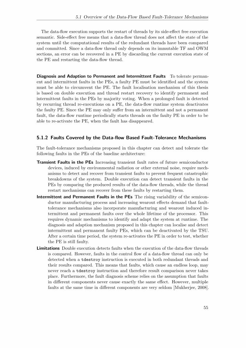
5.1 Overview of the Data-Flow Based Fault-Tolerance Mechanisms
The data-flow execution supports the restart of threads by its side-effect free executionsemantic. Side-effect free means that a data-flow thread does not affect the state of thesystem until the computational results of the redundant threads have been comparedand committed. Since a data-flow thread only depends on its immutable TF and OWMsections, an error can be recovered in a PE by discarding the current execution state ofthe PE and restarting the data-flow thread.
Diagnosis and Adaption to Permanent and Intermittent Faults To tolerate perman-ent and intermittent faults in the PEs, a faulty PE must be identified and the systemmust be able to circumvent the PE. The fault localisation mechanism of this thesisis based on double execution and thread restart recovery to identify permanent andintermittent faults in the PEs by majority voting. When a prolonged fault is detectedby recurring thread re-executions on a PE, the data-flow runtime system deactivatesthe faulty PE. Since the PE may only suffer from an intermittent and not a permanentfault, the data-flow runtime periodically starts threads on the faulty PE in order to beable to re-activate the PE, when the fault has disappeared.
5.1.2 Faults Covered by the Data-flow Based Fault-Tolerance Mechanisms
The fault-tolerance mechanisms proposed in this chapter can detect and tolerate thefollowing faults in the PEs of the baseline architecture:
Transient Faults in the PEs Increasing transient fault rates of future semiconductordevices, induced by environmental radiation or other external noise, require mech-anisms to detect and recover from transient faults to prevent frequent catastrophicbreakdowns of the system. Double execution can detect transient faults in thePEs by comparing the produced results of the data-flow threads, while the threadrestart mechanisms can recover from these faults by restarting them.
Intermittent and Permanent Faults in the PEs The rising variability of the semicon-ductor manufacturing process and increasing wearout effects demand that fault-tolerance mechanisms also incorporate manufacturing and wearout induced in-termittent and permanent faults over the whole lifetime of the processor. Thisrequires dynamic mechanisms to identify and adapt the system at runtime. Thediagnosis and adaption mechanism proposed in this chapter can localise and detectintermittent and permanent faulty PEs, which can be deactivated by the TSU.After a certain time period, the system re-activates the PE in order to test, whetherthe PE is still faulty.
Limitations Double execution detects faults when the execution of the data-flow threadsis compared. However, faults in the control flow of a data-flow thread can only bedetected when a tdestroy instruction is executed in both redundant threads andtheir results compared. This means that faults, which cause an endless loop, maynever reach a tdestroy instruction and therefore result comparison never takesplace. Furthermore, the fault diagnosis scheme relies on the assumption that faultsin different components never cause exactly the same effect. However, multiplefaults at the same time in different components are very seldom [Mukherjee, 2008].
55
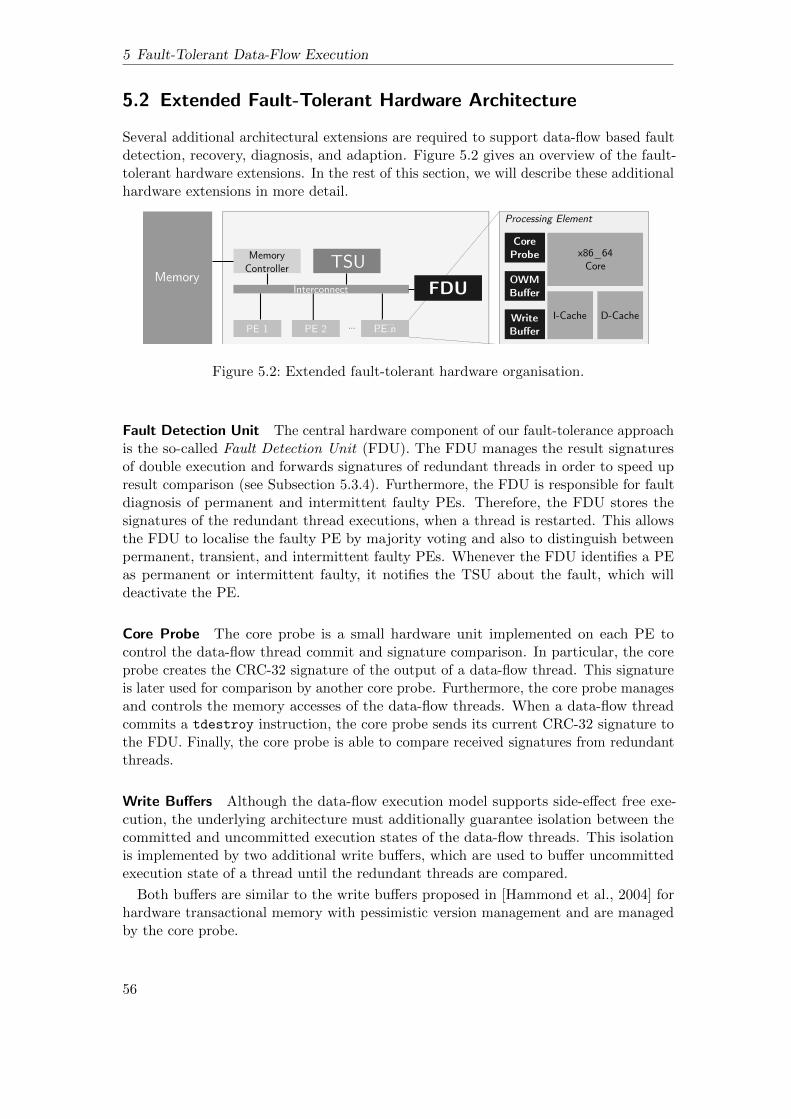
5 Fault-Tolerant Data-Flow Execution
5.2 Extended Fault-Tolerant Hardware Architecture
Several additional architectural extensions are required to support data-flow based faultdetection, recovery, diagnosis, and adaption. Figure 5.2 gives an overview of the fault-tolerant hardware extensions. In the rest of this section, we will describe these additionalhardware extensions in more detail.
FDU
ff
ff
Figure 5.2: Extended fault-tolerant hardware organisation.
Fault Detection Unit The central hardware component of our fault-tolerance approachis the so-called Fault Detection Unit (FDU). The FDU manages the result signaturesof double execution and forwards signatures of redundant threads in order to speed upresult comparison (see Subsection 5.3.4). Furthermore, the FDU is responsible for faultdiagnosis of permanent and intermittent faulty PEs. Therefore, the FDU stores thesignatures of the redundant thread executions, when a thread is restarted. This allowsthe FDU to localise the faulty PE by majority voting and also to distinguish betweenpermanent, transient, and intermittent faulty PEs. Whenever the FDU identifies a PEas permanent or intermittent faulty, it notifies the TSU about the fault, which willdeactivate the PE.
Core Probe The core probe is a small hardware unit implemented on each PE tocontrol the data-flow thread commit and signature comparison. In particular, the coreprobe creates the CRC-32 signature of the output of a data-flow thread. This signatureis later used for comparison by another core probe. Furthermore, the core probe managesand controls the memory accesses of the data-flow threads. When a data-flow threadcommits a tdestroy instruction, the core probe sends its current CRC-32 signature tothe FDU. Finally, the core probe is able to compare received signatures from redundantthreads.
Write Buffers Although the data-flow execution model supports side-effect free exe-cution, the underlying architecture must additionally guarantee isolation between thecommitted and uncommitted execution states of the data-flow threads. This isolationis implemented by two additional write buffers, which are used to buffer uncommittedexecution state of a thread until the redundant threads are compared.
Both buffers are similar to the write buffers proposed in [Hammond et al., 2004] forhardware transactional memory with pessimistic version management and are managedby the core probe.
56

5.3 Double Execution of Data-Flow Threads
• Write Buffer: twrite/twritep/tdecrease instructions executed by a PE maycontain errors. In order to guarantee fault isolation and hence avoid the possibilitythat errors can modify the global state of the system, i.e. manipulating thesynchronisation count of a wrong thread or overwriting data at the wrong address,buffering of those instructions is necessary. The write buffer stores all twrite/twritep/tdecrease instructions until the core probe has compared its signaturewith the signature of the redundant thread. When no error was detected, the PEthen forwards all buffered instructions to the TSU, which processes them in theusual way, i.e. decreases the target thread’s synchronisation counts and stores datain the TFs of subsequent threads.
• OWM Buffer: Stores to the OWM sections must be also isolated. Therefore, toidentify OWM accesses of a thread, the core probe stores the start pointer andthe length of the complete OWM region. Whenever a store accesses this region,the store is buffered in the OWM buffer until the thread finishes execution and isallowed to commit. By contrast to the write buffer, the OWM buffer must be fullyassociative, since values stored in the write buffer may be re-used by the samethread.
5.3 Double Execution of Data-Flow Threads
Double execution (DE) is a loosely-coupled redundant execution scheme, which supportsdecoupled redundant execution of data-flow threads. Compared to prior loosely-coupledredundant execution mechanisms, like [Rotenberg, 1999; LaFrieda et al., 2007; Rashidet al., 2008; Reinhardt et al., 2000], double execution makes use of the data-flowexecution principle for fault detection. In particular, data-flow execution is leveraged forinput replication, redundant thread synchronisation, and output comparison. Beside theadvantages inherent to loosely-coupled redundant execution mechanisms (see Section 2.3),double execution supports decoupled, asynchronous execution of redundant data-flowthreads, which does not require hardware based permanent coupling between redundantPEs, reduces the performance degradation when PEs are permanently faulty and providessupport for asynchronous execution of redundant threads.
5.3.1 Double Execution Overview
In the following, we will describe how the data-flow execution model facilitates inputreplication, thread synchronisation, and output comparison.
2A thread is duplicated when its synchronisation count becomes zero, i.e. a thread hasreceived all its inputs and is ready for execution. Similar to [Reinhardt et al., 2000], wecall the duplicated thread trailing thread and its copy leading thread. The terms trailingand leading are used to distinguish between the start time of the threads, which meansthat the leading thread is always started before the trailing thread. However, due tothe decoupled execution of both threads, it may happen that the trailing thread finishesbefore the leading thread. To duplicate a thread, the TSU, which keeps all continuationsin the system, creates a copy of the original continuation. To indicate the thread’s
2The rest of this section is a revised part of [Weis et al., 2016].
57
5 Fault-Tolerant Data-Flow Execution
duplication, the TSU sends a notification message with the thread IDs of the leading andthe trailing thread to the FDU. While the redundant threads have different continuationsand IDs, they share the same TF and OWM. Furthermore, the TSU scheduler ensuresthat leading and trailing threads never share the same PE to support the localisation ofpermanent and intermittent faults.
After the continuation has been copied, both threads can be independently scheduledand executed on different PEs without synchronisation. During execution, the core probecreates a CRC-32 signature of the threads’ output.
When the leading thread finishes execution, the core probe sends the CRC-32 signatureto the FDU, which immediately forwards the signature to trailing thread’s core probe,The core probe of the trailing thread’s PE compares its signature with the forwardedsignature from the FDU and signals the TSU and the FDU the commitment or a detectederror. In the fault-free case, the trailing thread is committed, similar to the executionin the baseline system. When a fault has been detected by the core probe, the FDUtriggers a thread restart, described in Section 5.4.
Figure 5.3 shows the execution stages of double execution:
Figure 5.3: Execution stages of double execution.
1 Thread start The leading thread is immediately started when a PE becomesavailable. The trailing thread is started when the next PE becomes available. The timebetween the start of the leading thread and the trailing thread is called start slack. Sincethreads are started on their availability, the start slack is influenced by the utilisation ofthe system.
58

5.3 Double Execution of Data-Flow Threads
2 Thread execution During execution, the PE of the trailing thread buffers itsresults in the write buffers (write buffer and OWM buffer). Simultaneously, the coreprobe creates a CRC-32 signature the thread output.
The core probe of the leading thread’s PE also creates a CRC-32 signature of its output,however, after signature creation, the output of the leading thread can be discarded,with exception of the OWM writes, which can be only discarded after the leading threadhas reached the tdestroy instruction.
3 Thread end: When the leading thread has finished execution, indicated by atdestroy instruction, the core probe sends the CRC-32 signature to the FDU, whichimmediately forwards the signature to the trailing thread’s core probe. Since the outputof the leading thread was not buffered, the PE of the leading thread is immediatelyready for execution of the next waiting data-flow thread in the TSU’s RQ. By contrast,the trailing thread’s PE has buffered the trailing thread’s output and must wait untilsignature comparison allows the commitment.
4 Output comparison: The core probe of the trailing thread’s PE compares thesignatures of the redundant threads. Additionally, the FDU, which has been notified bythe TSU on duplication of the redundant continuation, waits for the signatures of theleading and the trailing thread, compares them again and stores the result per PE. Incase of a mismatch of the signatures, the FDU keeps the signatures for later majorityvoting in order to localise the faulty PE.
5 Thread commit or recovery: In case of a non-faulty execution of both threads,the core probe of the trailing thread commits the write buffer and the OWM buffer.After commit of the trailing thread, the TSU deletes the continuations of both threads.When a fault was detected, the core probe of the trailing thread’s PE flushes the buffersand informs the TSU to trigger a thread restart.
5.3.2 Sphere of Replication of Double Execution
As described in Section 2.3, the sphere of replication defines the hardware regionof a redundant execution scheme, where components are either spatial or temporalredundant. Within the sphere of replication faults can be detected by a redundantexecution mechanism. However, input data that enters the sphere must be replicatedin a consistent manner for both execution streams. Furthermore, data that leaves thesphere of replication must be checked for faults, otherwise faults can not be detected ata later stage.
Figure 5.4 shows the sphere of replication of double execution for the enhanced fault-tolerant architecture. The sphere is restricted to the PEs of the system, excluding thelocal caches, the core probes, and the write buffers. As a consequence, these hardwarecomponents must be protected by other fault-tolerance mechanisms.
Beside the PEs, the baseline architecture also includes several single-point-of-failurehardware components, e.g. the interconnect, the memory controller, the FDU, and theTSU. For the interconnect, we assume an end-to-end ECC implementation, which is ableto detect and correct transient faults. Permanent faults within the interconnect are outof scope of this thesis, nevertheless fault-tolerant network-on-chip techniques, as theyare discussed in [Garbade, 2014], can be additionally implemented.
59

5 Fault-Tolerant Data-Flow Execution
Figure 5.4: Sphere of replication for double execution.
Furthermore, all off- and on-chip memory structures, which are not part of the sphereof replication must be protected by information redundancy mechanisms as well, e.g.ECC. In the case of a permanent broken DRAM chip, chipkill memory [Dell, 1997] couldbe implemented to dynamically cope with broken memory chips. Fault-tolerant memoryis of particular importance, since the data-flow based fault-tolerance mechanisms requirethe main memory to store the current state of the system.
For all other non-redundant components, e.g. the memory controller, the FDU, orthe TSU, we do not assume additionally fault-tolerance mechanisms, however, spatialredundancy can be implemented for all of them. Nevertheless, spatial redundancy ofthese components does not directly influence the data-flow thread execution and istherefore left for future work.
5.3.3 Input Replication
As double execution uses data-flow threads for redundant execution, the input data ofthe redundant threads must be consistently replicated. The following input values mayenter the sphere of replication during execution:
• TLS Reads: The redundant threads can read from the TLS, which stores athread’s private stack and heap. Since the TLS is private per data-flow threadand exclusively created for each thread, it must not explicitly replicated for doubleexecution.
• OWM Reads: Writes to the OWM region must be buffered until the redundantthreads are verified. Hence, writes to the OWM region can only become globallyvisible when the thread commits. This means that reads from the redundantthreads can share the same OWM section, since the OWM section will not changeuntil the execution of the trailing thread is verified and committed.
• Thread Frame Reads: The TF is immutable after the synchronisation count hasreached zero, which allows redundant threads to read from the same TF, becausedata inconsistencies between redundant threads, induced by race conditions ofconcurrent twrites, are impossible.
3Beside the read accesses discussed before, the leading and trailing threads may executetschedule instructions to dynamically allocate subsequent threads. If the TSU receives
3This paragraph has also been published in [Weis et al., 2016].
60

5.3 Double Execution of Data-Flow Threads
PE 2
Figure 5.5: Consistent input replication for redundant tschedule instructions.
a tschedule request from a PE, a new continuation is created and a new TF, whichis required to store the thread’s input data, is allocated. The TSU finally returns theID of the newly created thread. However, the returned ID is run time dependent andmay be later passed to subsequent TFs by twrite instructions. To ensure equal outputfor the leading and trailing threads, the received IDs must be equal for the trailing andthe leading threads. However, the redundant thread execution is not synchronised oninstruction level and it may happen that a leading thread runs behind its trailing threador vice versa. In order to prevent stalls induced by tschedule synchronisation betweenleading and the trailing threads, we allow both PEs to issue tschedule instructions.To guarantee consistent IDs in the leading and the trailing thread, the TSU followsthe algorithm depicted in Algorithm 5.1. Therefore, the TSU maintains a counter percontinuation (tsched count), which keeps the number of issued tschedule instructionsper thread. When a thread has issued a tschedule request, the TSU compares thetsched count in its continuation with the tsched count of the redundant thread. If thetsched count is greater than the tsched count of the redundant thread, the TSU knowsthat the calling thread is running ahead of its redundant copy. In this case, the TSUprocesses the tschedule request as usual and stores the created thread ID in the IDTable (see Section 5.5.2). If the tschedule count is lower than the tsched count ofthe redundant thread, the TSU has already processed this tschedule request from theredundant thread, which is running ahead. In this case, the TSU proceeds with an IDTable look up to retrieve the previously stored thread ID, created by the redundantthread’s tschedule, which is running ahead.
Example. Figure 5.5 depicts an example execution of a redundant tschedule execution.
1 It can be seen that PE 1 executes the leading thread, which issues a tschedule
instruction. The TSU now compares the tsched count of the leading thread with thetsched count of the trailing thread. Since no thread has executed a tschedule at this
61
5 Fault-Tolerant Data-Flow Execution
point, the TSU processes the tschedule and increments the tsched count of the leadingthread and stores the new thread ID (id = 3) in the ID Table. 2 Afterwards, PE 2,which executes the trailing thread, executes a tschedule instruction. The tsched countof the leading thread is now greater (tsched countleading > tsched counttrailing) thanthe trailing thread, in this case the TSU retrieves the previously stored thread ID fromthe ID Table (id = 3). ♦
Algorithm 5.1 Replication of a thread ID for a redundant tschedule instruction.
Input: sc // synchronisation countOutput: id = tschedule(sc)if tsched countcaller ≤ tsched countredundant then // thread is behind
id← retrieve from ID Tableelse // thread is aheadid← process tschedule(sc)
end ifreturn id
5.3.4 Synchronisation and Output Comparison
Leading and trailing threads are synchronised for comparison on thread commit. Likewise,the synchronisation frequency depends on the length of the data-flow threads. As aconsequence, the granularity of double execution thread synchronisation can not beadapted at run time and depends on the data-flow application. Unfortunately, faultscan only be detected when the leading and trailing thread synchronise, which meansthat the worst case fault detection latency depends on the start slack of the redundantthreads, their execution speed, and the length of the threads.
Data, which leaves the sphere of replication and changes the global state of the systemmust be verified for errors. For data-flow threads, the following output leaves the sphereof replication and can manipulate the global system state:
• Writes to the thread frame: Data-flow threads use twrite/twritep instruc-tions to write to TFs of subsequent threads. Furthermore, tdecrease instructionsmanipulate the synchronisation count of waiting threads in the TSU.
• Writes to the OWM: Writes to the OWM become only visible after a thread iscommitted.
• Scheduling of new threads: Data-flow threads can spawn new threads bytschedule instructions.
All other memory accesses of the threads are only allowed to manipulate thread-localdata, which does not directly influence the global state of the system. However, anerror that has been temporary stored in the thread-local storage may be later passed tosubsequent thread frames or the OWM region.
Therefore, output comparison for double execution needs to incorporate all twrite/twritep/tdecrease buffered in the write buffer, writes to the OWM region buffered inthe OWM buffer, and all executed tschedule instructions.
62
5.3 Double Execution of Data-Flow Threads
Result Compression In order to save interconnection bandwidth and result comparisonlatency, the output of a thread is reduced to a CRC-32 signature, similar to the fingerprinttechnique proposed by Smolens et al. [2006]. As a consequence, the CRC-32 signatureis updated on every twrite/twritep/tdecrease, every write to the OWM buffer, andevery tschedule. For twrite and twritep instructions, the target thread’s ID, theaddress and the value must be incorporated in the signature. For stores to the OWMsection the address and the value must be incorporated. For the tschedule, the addressof the thread’s code region and the synchronisation count must be incorporated in thesignature. For the tdecrease, the target thread’s ID and the value are incorporated.
Compared to [Smolens et al., 2006], double execution does not require creating asignature of the complete context of each PE and all store instructions, which reducesthe pressure on the CRC hardware in the core probe.
Reducing the PE Blocking Time Double execution implements fault isolation on PElevel, which simplifies the recovery mechanisms, as proposed in Section 5.3. However,the output of the trailing thread must be buffered in the PE until the signatures of boththreads have been compared. As a consequence, the PE that has executed the trailingthread is blocked until commit or recovery. Furthermore, when the leading thread finishesafter the trailing thread, the waiting time increases. Although this method supports fastrecovery by only discarding the execution state of the trailing and leading thread’s PE,it may introduce additional overhead by blocking of the PE until signature comparison,because the blocking time of the processing element depends on the comparison latency.This means that the comparison latency is on the critical path of the execution, since itdirectly increases the PE blocking time of the trailing thread.
However, the commit slack, i.e. the time difference between the commit of the trailingand the leading thread, can be used to mask the comparison latency by transferring thesignature of the leading thread to the trailing thread’s PE core probe, while the trailingthread is still executed. The evaluation results in Chapter 7 show that this techniquecan significantly reduce the average PE blocking time of the trailing thread.
5.3.5 Asynchronous Thread Execution
After the synchronisation count of a thread has reached zero and a thread is duplicated,both threads can be independently scheduled. This means that both threads can beexecuted completely asynchronous on different PEs. The start slack depends on thePE availability at run time. Nevertheless, the TSU tries to execute leading and trailingthreads in parallel to limit the start and commit slack. The decoupled redundant threadexecution allows for flexible utilisation of the available PEs. In the case of permanentfaults, the system can efficiently exploit the remaining PEs even when an uneven numberof PEs is left operational.
Example. Figure 5.6 shows the flexibility of the asynchronous thread execution on asystem with 4 PEs. In Figure 5.6(a) it can be seen that the threads T1, T1’, T2, andT2’ are executed in parallel. However, when in Figure 5.6(b) PE4 becomes permanentfaulty, the TSU can only execute T2’ on PE3 and must wait for the next available PE toschedule T2. Since the next available PE is PE2, the TSU schedules T2 to PE2. In thiscase, T2 is executed completely time-shifted with respect to the leading thread T2’. ♦
63

5 Fault-Tolerant Data-Flow Execution
PE1
PE2
PE3
PE4
Time
T0'
T1
T1'
T2'
T2
T3'
T3T0
(a) Double execution on four PEs.
PE1
PE2
PE3
PE4
Time
T0'
T1
T1'
T2'
T2
T3'
T3T0
Permanent Faulty
(b) Double execution on four PEs with one per-manent faulty PE.
Figure 5.6: Asynchronous execution of redundant threads.
5.3.6 Influence of Double Execution on the Execution Time
Beside the doubled PE utilisation inherent to all redundant execution schemes, theoverhead of double execution compared to conventional data-flow execution is influencedby two factors: The deferred commit and the PE blocking of the trailing thread.
Deferred Commit For the global progress of the system, double execution looks likenon-redundant data-flow execution, since only the trailing thread is allowed to commit.However, compared to non-redundant data-flow execution, the time between start (of theleading thread) and commit (of the trailing thread) is longer than for a non-redundantexecution of the same thread. The deferred commit of the trailing thread can reduce theparallelism in the system, since subsequent threads can only be started when both theleading and the trailing threads have finished their execution.
PE Blocking of the Trailing Thread While the PE of the leading thread is immediatelyrelinquished for subsequent threads after tdestroy has been retired, the trailing threadhas to buffer the results of the data-flow execution in its write buffers. During resultcomparison, the PE can not execute subsequent data-flow threads, since the PE’s writebuffers would be otherwise overwritten. Therefore, the PE of the trailing thread isblocked for further data-flow threads until the FDU has finished result comparison. Theblocking time of the PE is minimised, when the leading thread always finishes executionbefore the trailing thread. In this case, the PE is blocked for other leading threads untilthe core probe has received and compared the signature from the leading thread. Thecommit slack between the redundant threads can reduce the PE blocking time inducedby the result comparison latency, as described in Section 5.3.4.
5.4 Restart of Data-Flow Threads
This section describes the data-flow based thread restart mechanism to recover fromerrors. The buffers of the PEs prevent that an unverified trailing thread can modifythe global state of the system, i.e. TFs of subsequent threads, the synchronisationcounts of waiting data-flow threads in the TSU, or the OWM region. As a consequence,error propagation for double execution is restricted to the PEs. Since no global state ismanipulated until double execution has verified the thread execution, the main memory
64

5.5 Data-Flow Runtime Enhancements
must not be recovered. This means that the data-flow thread execution creates inherentexecution checkpoints on each thread commit. The valid and fault-free checkpoint stateconsists of the global state of the system, i.e. the thread frames and the OWM regionin the main memory and all continuations within the TSU, which are not marked asspeculative (see Subsection 5.4.1). When a redundant thread pair commits, a newcheckpoint is implicitly created. Hence, the unsafe, recoverable state consists of theexecution state of a thread, including the PE context, the buffers, and the TLS.
When the core probe detects a signature mismatch, the TSU discards the uncommittedstate of the faulty threads, i.e. the buffers of the waiting thread’s PE’s and all speculativelycreated continuations. Afterwards, the TSU restarts the redundant threads.
The overhead in case of a fault is dominated by the wasted execution time for therestarted threads. Since double execution can detect errors only when both threadscommit, the wasted execution time depends on the start slack, the length of the data-flowthreads of the executed application, and the execution speed of the redundant threads.
5.4.1 Speculative Thread Creation
Data-flow threads can schedule new threads by executing the tschedule instruction.In this case, a new continuation is created within the TSU and a new TF is allocated.However, in case of a thread restart, the same tschedule instruction will be executedagain. To prevent multiple thread creations in such a case, all scheduled threads aremarked as speculative in the TSU until the parent thread has been checked for errors.When a redundant thread pair is restarted, all speculatively created threads must bediscarded. In order to do so, the ID of the parent trailing thread is stored in eachcontinuation. In case of a thread restart, the TSU deletes all speculative continuationscreated by the erroneous thread and releases the allocated TFs of the threads.
Please note that the TSU will never schedule a thread to a PE when its continuationis marked as speculative. After result comparison and commitment of the trailing thread,the TSU changes all successor threads from speculative to non-speculative.
5.5 Data-Flow Runtime Enhancements
Double execution requires changes to the baseline execution model and architecture. Inparticular, the data-flow runtime must be able to create and manage redundant threads,create CRC-32 signatures, and support deterministic tschedule input replication forthe redundant threads.
This section describes the necessary enhancements to the TSU to support doubleexecution and thread restart recovery.
5.5.1 Extended Continuation for Double Execution
Figure 5.7 shows the extended continuations of the trailing and leading thread withthe additionally allocated thread local storage for the redundant thread. We added thefollowing fields to the original continuation:
• trail (Trailing Thread): indicates, whether the thread is a trailing thread.
65

5 Fault-Tolerant Data-Flow Execution
Code
ThreadFrame
Thread Local Storage (Leading)
Memory of the
Leading and Trailing
Thread
Leading Thread's Continuation
Thread Local Storage (Trailer)
id tsched_countfp ip sc tlsp trail red_cont spec parent_id pe_id free_ptr next_ptr
Trailing Thread's Continuation
id tsched_countfp ip sc tlsp trail red_cont spec parent_id pe_id free_ptr next_ptr re-start
re-start
Figure 5.7: Redundant continuations and memory organisation of double execution.
• red cont (Redundant Continuation Pointer): stores the thread ID of the redundantcontinuation.
• spec (Speculative Thread): indicates, whether the thread is speculative.
• parent id (Parent ID): stores the thread ID of the parent thread. The parent ID isrequired to discard the speculative continuations, if the parent thread needs to berestarted.
• tsched count (tschedule Count): stores the number of issued tschedule instruc-tions of the thread.
• pe id (PE ID): stores the ID of the PE, which has executed the thread.
• free ptr (ID Table Free Pointer): points to the next free entry in the ID Table.
• next ptr (ID Table Next ID Pointer): points to the next thread ID in the ID Tableto be returned on a redundant tschedule.
• re-start (Restarted Flag): indicates whether the thread has been restarted.
Please note that the synchronisation count of the redundant thread is always zero,since the redundant continuation is only created, when the synchronisation count of theoriginal thread became zero.
5.5.2 ID Table
As described in Section 5.3.3, double execution requires deterministic thread IDs returnedon redundant tschedules to guarantee consistent input replication. The TSU musttherefore temporarily store the created thread IDs and their sequential order. This issupported by the ID table, which allows storing and retrieving thread IDs in case ofredundant tschedule instructions. The TSU keeps all IDs created on tschedule in anadditional memory structure, the ID table. The ID table stores the thread ID of the
66

5.6 Fault Diagnosis and Periodic Tests
trailing thread together with the newly created thread ID, when a tschedule has beenexecuted for the first time.
To support fast access, a thread’s continuation maintains two additional pointers, onewhich stores the index of the next thread ID (next ptr) to be returned and another one,which points to the next free entry in the ID Table (free ptr) (see Figure 5.8(a)). Afterthe TSU has returned a thread ID stored in the ID table, it tries to find the next ID tobe returned by traversing the list until the next ID of the leading thread is found (seeFigure 5.8(b)).
ID Table
free_ptr
next_ptr
Leading Thread ID Successor ID
1
1
1
3
4
5
(a) ID Table with next ptr and free ptr.
ID Table
free_ptr
next_ptr
Leading Thread ID Successor ID
1
1
4
5
1 3
(b) ID Table after trailing tschedule.
ID Table
free_ptr
next_ptr
Leading Thread ID Successor ID
1
1
4
5
1 6
1 3
(c) ID Table after leading tschedule.
Figure 5.8: ID table for redundant tschedule.
When a new entry is entered, the TSU uses the free ptr in the continuation to storethe leading thread’s ID together with the new ID. Afterwards, the free pointer is movedto the next empty entry in the list (see Figure 5.8(c)). To support the fault localisationmechanism proposed in Section 5.6, the entries in the ID Table are only removed in caseof a fault-free execution.
5.6 Fault Diagnosis and Periodic Tests
Fault diagnosis and adaption are necessary to cope with permanent and intermittentfaults. For instance, a permanent fault in a PE may lead to continuing recovery actions,bringing the complete system to a halt [Sorin, 2009]. To prevent such situations, theFDU identifies permanent or intermittent faulty PEs and instructs the TSU to deactivatethe faulty PE.
The technique is based on the fault detection and recovery mechanisms proposedin the Sections 5.3 and 6.1. Here, the FDU works as a fault diagnosis unit, whichtracks detected errors per PE and determines whether a PE is transient, intermittent, orpermanent faulty.
67
5 Fault-Tolerant Data-Flow Execution
The FDU can also be used to track thermal condition or detected errors by other faultdetection mechanisms, like the machine check architecture (MCA), however, advancedproactive mechanisms based on these information are out of scope for this thesis. Forfurther ideas on proactive fault management by the FDU please refer to Weis et al.[2011b].
5.6.1 Fault Diagnosis
The FDU stores all received signatures of the threads to localise the faulty component.This is possible since the signatures of the restarted threads are always equal in theabsence of errors. When the FDU receives the signatures of the thread re-executions,the PE, which suffered from the fault can be identified by a majority voting. Underthe assumption that faults in different PEs never produce the same signature, the FDUcan identify the erroneous thread execution and assume that the PE, which producedan error, has suffered from a fault. However, the scheduler must ensure that in thecase of a re-execution at least one thread uses a different PE. Furthermore, re-executedthreads always use the ID Table to retrieve the same thread IDs as the execution before.After having identified the correct signature, we can consider all diverging signatures aserroneous.
During execution, the FDU continuously tracks all identified faulty PEs and storesthem in the knowledge base. The knowledge base uses a list per PE to keep the localisedfaults as binary values. A bit value indicates, whether a fault has been localised for thisPE. The FDU also distinguishes between transient and permanent faulty PEs. In orderto do so, it looks in its knowledge base, whether the last execution localised a fault onthis PE, too. In this case, the PE is considered as permanent faulty. When a PE isidentified to be permanent faulty, the FDU informs the TSU to deactivate the PE.
Example. Figure 5.9 shows how the permanent faulty PE 3 can be localised. First, theredundant threads are executed on PE 2 and PE 3. On result comparison, an error isdetected. However, the FDU does not know, which PE produced the error, stores thesignatures produced by the threads and restarts them. The redundant thread pair isre-started on PE 1 and PE 3. Since PE 3 is still permanent faulty, the FDU detects anerror again. The FDU now uses majority voting to detect that PE 1 and PE 2 haveproduced the same signature. After result comparison, the FDU updates its knowledgebase about PE 1 and PE 3. Since PE 3 suffered from two errors in a row, the FDUconsiders PE 3 as permanent faulty. ♦
5.6.2 Periodic Testing
The system uses periodic tests to check, whether a PE is still faulty. Generally, theFDU does never consider a PE as permanent faulty, but only assumes intermittentfaults. After a given number of n committed threads, the FDU re-tests a deactivatedPE. Therefore, it resets the state of the PE from faulty to operational. When the nextexecuted thread is faulty again, the test is repeated after n committed threads.
The test interval depends on the recovery overhead of the selected recovery mechanism.This means that periodic tests are cheaper for double execution with thread restartrecovery than optimistic double execution with global checkpointing (see Chapter 6).
68

5.6 Fault Diagnosis and Periodic Tests
FDU Knowledge Base
Time
Leading
Trailing
PE 2 PE 3 FDU
Comparison
send sig. 0xA
Error Detected
PE 1
send sig. 0xB
PE 1
PE 2
PE 3
(a) Double execution on PE 2 and PE 3, while PE 3 is permanent faulty. TheFDU detected a error and keeps the signatures produced by double execution.The TSU re-starts the threads, while at least one thread is executed on adifferent PE than before.
FDU Knowledge Base
Time
Trailing
PE 2 PE 3 FDU
Comparison
send sig. 0xA
send sig. 0xB
Error Detected
PE 1
Leading
Intermittent/Permanent Fault Detected
PE 1
PE 2
PE 31 1
(b) Double execution on PE 1 and PE 3, while PE 3 is permanent faulty. Afterthe erroneous execution was detected, the FDU compares the signatures of allthread executions. In this case, we can see that PE 1 and PE 2 have producedthe same signature, which means that PE 3 has produced the erroneous signature.Since PE 3 has produced an erroneous signature two times in a row, we storethat information in the knowledge base.
Figure 5.9: Fault diagnosis using double execution.
69

5 Fault-Tolerant Data-Flow Execution
5.7 Summary
This chapter proposed data-flow based fault-tolerance mechanisms to cope with transient,intermittent, and permanent faults in the processing elements of a multi-core architecture.Fault detection is implemented by double execution, a loosely-coupled redundant execu-tion scheme for data-flow threads. Double execution exploits the data-flow executionprinciple of the baseline architecture for input replication, redundant thread management,and output comparison. Based on double execution, a data-flow thread restart recoverymechanism was proposed. The required enhancements for double execution and threadrestart recovery to the data-flow execution model and the hardware architecture werediscussed in detail. Additionally, a fault diagnosis mechanism was proposed, which usesdouble execution and the thread restart recovery for fault localisation.
The data-flow based fault-tolerance mechanisms proposed in this chapter provide thefollowing benefits:
1. Double execution uses data-flow threads for redundant execution. This allowsleveraging the data-flow runtime to execute redundant data-flow threads. Inparticular, the data-flow scheduler can dynamically schedule redundant threads onPE availability.
2. Result comparison is only necessary for data which is consumed by subsequentthreads. This reduces the amount of data, which must be compared.
3. Redundant data-flow threads can be executed completely decoupled from eachother, supporting a flexible utilisation of the baseline multi-core architecture.
4. Result propagation is only required when a thread has finished execution, whichsimplifies input replication, output comparison, and enables thread restart recovery.
5. Double execution and thread restart recovery can be used for the localisation andthe diagnosis of permanent and intermittent faulty PEs by the FDU.
6. The integration of double execution and thread restart recovery in the data-flowexecution model supports the flexible deactivation of permanent faulty PEs. Theasynchronous redundant thread execution can also exploit uneven numbers of PEs.
70

6Optimistic Double Execution andGlobal Checkpointing
This chapter presents in Section 6.1 Optimistic Double Execution (ODE), a speculativevariant of double execution, which can increase the parallelism of double execution. SinceODE can not recover from errors by the thread restart recovery mechanism proposed inChapter 5, Section 6.2 proposes a data-flow based global checkpoint mechanism. Finally,Section 6.3 gives a summary on the fault-tolerance mechanisms of this chapter.
6.1 Optimistic Double Execution
This section gives an overview of ODE. First, we describe how ODE can increase theparallelism of double execution of data-flow threads. Second, we present the executionbehaviour of ODE. Third, we discuss input replication and output comparison for ODEand present a mechanism for the input replication of the OWM sections.
6.1.1 Increasing Parallelism by Optimistic Thread Commit
The parallelism of double execution is restricted by the parallelism of the data-flowapplication, since redundant threads must always be compared before the commit of thetrailing thread and before subsequent threads can be started. As a consequence, thescalability of double execution is limited by the parallelism of the data-flow applicationand can not be significantly higher than the execution on a non-fault tolerant systemwith half of the cores.
To overcome this restriction of double execution, ODE speculates that the redundantthread execution is always correct and allows forward progress by committing the leadingthread before the trailing thread has finished execution or is even started. This enablesto optimistically start subsequent threads before the trailing thread has verified theexecution and therefore increases the parallelism. Optimistic double execution enables acomplete decoupling of the leading and the trailing threads, since the system can make
71

6 Optimistic Double Execution and Global Checkpointing
(a) Dynamic data-flow graph ofdouble execution.
PE 1
PE 2
PE 3
PE 4
Leading Thread
Trailing Thread
T0
T'0
'
PE 1
PE 2
PE 3
PE 4
Time
Optimistic Double Execution
Double ExecutionT1
T'1
T2
T'2
T3
T'3
T4
T'4
T5
T'5
tODE tDE
T0
T'0
'
T1
T2
T3
T'1
T'2
T'3
T4
T'4
T5
T'5
(b) Thread execution of double execution and optimistic double execution.
Figure 6.1: Example for increasing parallelism by the optimistic thread commit of ODE.
forward progress without waiting for the signature comparison by the trailing threadsand can defer the verification by the trailing threads to a later point in time.
As mentioned before, the optimistic commit of the leading thread can increase theparallelism, since the parallelism of double execution is restricted by the dependenciesbetween the data-flow threads. However, in case of ODE, the data dependencies betweenthe threads restrict only the execution of the leading threads, but not the executionof the trailing threads, because the trailing threads’ dependencies have already beenresolved when the threads were duplicated.
Example. Figure 6.1 shows by example the increasing parallelism in case of ODE. Thedynamic data-flow graph of double execution, depicted in Figure 6.1(a), is executed bydouble execution and ODE on a system with 4 PEs in Figure 6.1(b). In the exampleexecution for double execution in Figure 6.1(b) it can be seen that the data dependenciesrestrict that the application can fully utilise the system, since T4 and T ′
4 can only be
72

6.1 Optimistic Double Execution
started when T1...T3 and T ′1...T
′3 have finished execution. By contrast, ODE fully utilises
the system to finish the threads T1...T3. Since ODE commits threads before the trailingthread has verified the computation, T4 and T ′
4 become ready for execution sooner andcan run in parallel to the trailing threads T ′
2 and T ′3. It can be further seen that the
trailing threads T ′2, T
′3, and T ′
4 can be executed in parallel, which increases the parallelismof the execution of the trailing threads and reduces the execution time of the data-flowapplication, since tODE < tDE. ♦
6.1.2 Run time Behaviour of Optimistic Double Execution
The run time behaviour of ODE can be divided into the following stages:
1 Thread start: Similar to double execution, the leading and trailing thread arestarted when a PE becomes available.
2 Thread execution: When the threads are executed, the leading thread’s PEbuffers all twrite/ twritep/tdecrease instructions in the write buffer and the OWMbuffer. Simultaneously, the core probe creates the CRC-32 signature, similar to doubleexecution. The core probe of the trailing thread’s core creates also the signature of itsoutput.
3 Thread end: When the leading thread has finished execution, indicated bytdestroy, the PE’s core probe sends the CRC-32 signature to the FDU. Afterwards,the leading thread immediately commits without waiting for the trailing thread and thesynchronisation counts of the succeeding threads are decremented instantaneous. TheTSU can then immediately start new threads, when their synchronisation counts hasreached zero.
4 Output comparison: The FDU waits for the signatures of both the leading andthe trailing threads and compares them.
5 Thread commit or recovery: In case of matching signatures, the TSU cancontinue execution. When a fault is detected, the FDU triggers the global recoverymechanism described in 6.2.
By contrast to double execution, ODE always schedules the trailing threads withlower priority than the leading threads, because only the leading threads can commit its(unverified) results and guarantee global progress of the system.
6.1.3 Input Replication
Similar to double execution, the input data must be replicated for the leading and trailingthreads. Since the TF of a data-flow thread is immutable and can not be modifiedafter the synchronisation count has reached zero, explicit duplication of the TF is notnecessary, even when the leading thread commits.
In case of double execution, stores to the OWM region do not require explicit inputreplication, because concurrent OWM stores to the same memory location are preventedby data dependencies in the data-flow graph. This means that parallel executabledata-flow threads can not write the same OWM addresses, while writes to the OWMregion of redundant threads are isolated from each others in the OWM buffer. However,ODE allows the leading thread to write (unverified and possible erroneous) output to the
73

6 Optimistic Double Execution and Global Checkpointing
Time
Leading
Trailing
TSU PE 1 PE 2 FDU
start
start
send sig. 1
ack
commit
1
2
3
45
send sig. 2commit
comp.
Figure 6.2: Execution stages of ODE.
OWM region. Furthermore, overwritten values in the OWM may be later required by thetrailing thread. This can lead to input incoherence between trailing and leading threads.To prevent input incoherence for OWM reads of redundant threads, the accessed partsof the OWM must be replicated before they can be changed by the leading thread’scommit. Therefore, the OWM section accessed by a thread must be copied before theleading thread can commit. To restrict the size of the copied section to a minimum,an additional instruction is used (owm mem), which is executed at the beginning of thethread to inform the TSU about the start address and the size of the OWM section.The owm mem instruction can be added by the compiler or the programmer and must beexecuted in both redundant threads. The TSU then initiates a replication of this sectionin the OWM region to prevent input incoherence between the trailing and the leadingthreads.
The management of the mapping between the original OWM section and the copiedsection is managed by the TSU by an OWM mapping table, depicted in Figure 6.3. Themapping table stores the ID of the trailing thread, the pointer to the original section,the pointer to the copied section, and the length of the section.
When the owm mem is executed the first time, the TSU searches in the OWM mappingtable, whether an entry for the trailing thread ID exists. If this is not the case, the TSUcreates a copy of the section specified by the owm mem instruction using a DMA transferand allocates a new entry in the OWM mapping table. When the trailing thread calls thesame owm mem instruction, the TSU searches again in the OWM mapping table for the
74

6.1 Optimistic Double Execution
Figure 6.3: OWM mapping table and pointers to the original and the copied OWMsections.
entry of the corresponding thread. The corresponding entry of the OWM mapping tableis then forwarded to the core probe. The core probe takes now care for the mapping andprevents the PE from writing to the original OWM region.
The core probe monitors all OWM read addresses of a PE and translates them to theappropriate physical addresses of the leading or trailing thread. As a consequence, theleading and trailing threads have different physical OWM addresses in the system. Thisprevents the leading thread from serving as a prefetcher for the trailing thread, sinceredundant threads read OWM input from different physical addresses.
Reducing the OWM Copy Overhead The copying of the trailing thread’s sharedmemory section can induce execution overhead, since the OWM section specified in theowm mem instruction must be copied before the leading thread can commit. To preventstalling of the trailing thread’s start, the OWM region is started immediately when theredundant threads become ready for execution and are moved to the RQ.
6.1.4 Output Comparison
Output comparison for optimistic double execution is similar to double execution, whichmeans that writes the OWM region, twrites, twriteps, tdecrease instructions, andtschedules must be incorporated in the CRC-32 signature. For the write accesses tothe OWM region, the original OWM addresses must be used for the trailing thread’ssignature.
75

6 Optimistic Double Execution and Global Checkpointing
6.2 Data-flow based Global Checkpointing
The optimistic thread commit of ODE before result verification allows that erroneousresults have already been committed to the main memory and the TSU and may beconsumed by subsequent threads before optimistic double execution can detect an error.This means that possible errors can no longer be isolated within the PEs and the restartof threads can not be used for recovery. As a consequence, in case of ODE, the TFs andthe OWM region may contain errors and must be recovered, when an error is detected.Since errors can be at any address in the memory after detection by ODE, the recoverymechanism must recover the complete main memory and the TSU state. This sectionproposes a data-flow based global checkpointing mechanism, which supports a globalrollback of the system, including the state of the TSU and the main memory. Theproposed checkpointing mechanism exploits the data-flow execution model to reduce thecheckpoint creation overhead.
6.2.1 Establishing a Checkpoint
Figure 6.4 shows the required steps to establish a global checkpoint with ODE:
1 To establish a global checkpoint, the FDU must ensure that the checkpoint issafe, i.e. error free. This means that all committed, but still unverified threadsmust be checked until the new checkpoint can be established. A new checkpointcan be only established, when all committed leading threads have been comparedwith their trailing thread counterparts. The TSU scheduler changes the schedulingpolicy when a checkpoint creation is triggered, prioritising the outstanding trailingthreads over the leading threads. The checkpoint interval can be therefore notexactly determined, since it depends on the number of unverified leading threadsin the RQ.
2 After all outstanding trailing threads have committed and their results have beencompared, a checkpoint can be established. The state of the system at this point iscalled the recovery point [Sorin, 2009], which is recovered in the case of a rollback.To create the checkpoint, the TSU determines the start and end addresses ofthe current frame memory region and the OWM region in the main memory.Furthermore, the TSU creates a backup of its current context, including all internaltables and stores it in the main memory, too. The global state of the system consistsof the TSU state, the thread frames and the OWM region, which is accessible byall threads.
3 After the checkpoint has been established, all subsequent twrite/twriteps goingto the checkpoint’s memory region will be logged. This means the TSU maintainsa log of all changes to the TFs within the checkpoint’s memory region. Newlyallocated TFs must not be recovered and are created outside of the checkpoint’slog region. Similar to the TF, a log over the complete OWM region is established,too.
4 When ODE detects a fault, the TSU recovers to the recovery point by restoringthe frame memory log, the OWM log, and the stored TSU context.
76
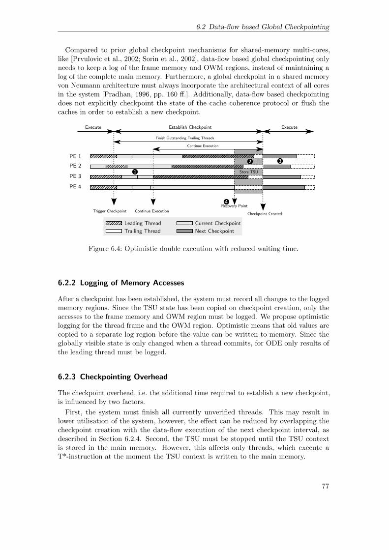
6.2 Data-flow based Global Checkpointing
Compared to prior global checkpoint mechanisms for shared-memory multi-cores,like [Prvulovic et al., 2002; Sorin et al., 2002], data-flow based global checkpointing onlyneeds to keep a log of the frame memory and OWM regions, instead of maintaining alog of the complete main memory. Furthermore, a global checkpoint in a shared memoryvon Neumann architecture must always incorporate the architectural context of all coresin the system [Pradhan, 1996, pp. 160 ff.]. Additionally, data-flow based checkpointingdoes not explicitly checkpoint the state of the cache coherence protocol or flush thecaches in order to establish a new checkpoint.
PE 1
Establish CheckpointExecute Execute
Finish Outstanding Trailing Threads
Continue Execution
PE 2
PE 3
PE 4
Trigger Checkpoint Continue ExecutionCheckpoint Created
Leading Thread
Trailing Thread
Current Checkpoint
Next Checkpoint
1
2 3
4Recovery Point
Store TSU
Figure 6.4: Optimistic double execution with reduced waiting time.
6.2.2 Logging of Memory Accesses
After a checkpoint has been established, the system must record all changes to the loggedmemory regions. Since the TSU state has been copied on checkpoint creation, only theaccesses to the frame memory and OWM region must be logged. We propose optimisticlogging for the thread frame and the OWM region. Optimistic means that old values arecopied to a separate log region before the value can be written to memory. Since theglobally visible state is only changed when a thread commits, for ODE only results ofthe leading thread must be logged.
6.2.3 Checkpointing Overhead
The checkpoint overhead, i.e. the additional time required to establish a new checkpoint,is influenced by two factors.
First, the system must finish all currently unverified threads. This may result inlower utilisation of the system, however, the effect can be reduced by overlapping thecheckpoint creation with the data-flow execution of the next checkpoint interval, asdescribed in Section 6.2.4. Second, the TSU must be stopped until the TSU contextis stored in the main memory. However, this affects only threads, which execute aT*-instruction at the moment the TSU context is written to the main memory.
77
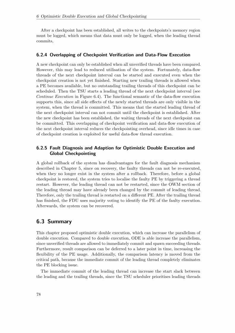
6 Optimistic Double Execution and Global Checkpointing
After a checkpoint has been established, all writes to the checkpoints’s memory regionmust be logged, which means that data must only be logged, when the leading threadcommits,
6.2.4 Overlapping of Checkpoint Verification and Data-Flow Execution
A new checkpoint can only be established when all unverified threads have been compared.However, this may lead to reduced utilisation of the system. Fortunately, data-flowthreads of the next checkpoint interval can be started and executed even when thecheckpoint creation is not yet finished. Starting new trailing threads is allowed whena PE becomes available, but no outstanding trailing threads of this checkpoint can bescheduled. Then the TSU starts a leading thread of the next checkpoint interval (seeContinue Execution in Figure 6.4). The functional semantic of the data-flow executionsupports this, since all side effects of the newly started threads are only visible in thesystem, when the thread is committed. This means that the started leading thread ofthe next checkpoint interval can not commit until the checkpoint is established. Afterthe new checkpoint has been established, the waiting threads of the next checkpoint canbe committed. This overlapping of checkpoint verification and data-flow execution ofthe next checkpoint interval reduces the checkpointing overhead, since idle times in caseof checkpoint creation is exploited for useful data-flow thread execution.
6.2.5 Fault Diagnosis and Adaption for Optimistic Double Execution andGlobal Checkpointing
A global rollback of the system has disadvantages for the fault diagnosis mechanismdescribed in Chapter 5, since on recovery, the faulty threads can not be re-executed,when they no longer exist in the system after a rollback. Therefore, before a globalcheckpoint is restored, the system tries to localise the faulty PE by triggering a threadrestart. However, the leading thread can not be restarted, since the OWM section ofthe leading thread may have already been changed by the commit of leading thread.Therefore, only the trailing thread is restarted on a different PE. After the trailing threadhas finished, the FDU uses majority voting to identify the PE of the faulty execution.Afterwards, the system can be recovered.
6.3 Summary
This chapter proposed optimistic double execution, which can increase the parallelism ofdouble execution. Compared to double execution, ODE is able increase the parallelism,since unverified threads are allowed to immediately commit and spawn succeeding threads.Furthermore, result comparison can be deferred to a later point in time, increasing theflexibility of the PE usage. Additionally, the comparison latency is moved from thecritical path, because the immediate commit of the leading thread completely eliminatesthe PE blocking issue.
The immediate commit of the leading thread can increase the start slack betweenthe leading and the trailing threads, since the TSU scheduler prioritises leading threads
78

6.3 Summary
over trailing threads. As a consequence, the commit slack between the leading and thetrailing threads can be significantly higher compared to double execution.
The duplication of the accessed OWM sections and the OWM mapping mechanismmay induce additional overhead and bus traffic. Furthermore, the OWM mapping mayincrease the cache occupancy and reduce the cache hit rate for OWM reads, becauseOWM read accesses from leading and trailing threads are mapped to different physicaladdresses.
Due to the speculative commit of unverified thread output, thread restart recoverycan not be used with optimistic double execution. Therefore, a data-flow based globalcheckpointing mechanism was proposed. The global checkpointing mechanism uses thedata-flow execution principle to reduce the checkpoint creation overhead by overlappingthe checkpoint creation time with data-flow thread execution and the logging overhead,by only logging changes to the OWM region and a part of the thread frame region.
79


7Evaluation
This chapter presents evaluation results of the proposed data-flow based fault-tolerancemechanisms. The section is structured as follows. Section 7.1 gives an overview ofthe simulation methodology, including a description of the simulator framework, theconfiguration of the simulator, and a characterisation of the data-flow benchmarks.Section 7.2 presents evaluation results on double execution and thread restart recovery.Section 7.3 presents results on optimistic double execution and data-flow based globalcheckpointing. Finally, Section 7.4 summarises the evaluation results.
7.1 Simulation Methodology
7.1.1 Simulator Framework
We used the open source full-system multi-core simulator COTSon [Argollo et al., 2009]for the evaluation of the proposed fault-tolerance mechanisms. The COTSon simulatorwas extended in the Teraflux project [Portero et al., 2012] with support for T*-baseddata-flow execution. For this evaluation, the proposed fault-tolerance mechanisms wereintegrated into COTSon, which enabled us to simulate double execution, thread restartrecovery, optimistic double execution, and data-flow based global checkpointing.
The COTSon simulator is a functional-first simulator, which simulates a group ofinstructions within a time quantum, calculates the timing for this quantum, and adjuststhe timing in the processor for the next simulation quantum. The length of the timequantum can be adjusted to trade simulation accuracy against simulation speed. For allsimulations in this thesis, a fixed quantum length of 500 ns is used.
7.1.2 Baseline Machine Configuration
Table 7.1 depicts the overview of the baseline machine configuration for this evaluation.The baseline machine models a contemporary x86 64 multi-core processor with 1, 2,4, 8, 16, or 32 PEs. The timing of a PE is calculated by an enhanced version of thetimer1 provided by the COTSon framework. The timer1 was extended with timingsupport for T*-instructions and also write and OWM buffer accesses. Each PE consists
81

7 Evaluation
of an out-of-order pipeline with 5 stages and a maximal fetch and commit width of 3instructions per cycle. The pipeline has a reorder buffer for 192 instructions. The privatecache hierarchy of each processing element consists of separate 32kB L1 instruction- anddata caches, which are connected to the main memory by a memory bus with a buslatency of 25 cycles. The memory bus uses the MOESI cache coherence protocol withsupport for cache-to-cache transfers.
Table 7.1: Baseline system configuration.
Parameters Values
Pipeline Out-of-order, Pipeline length: 5,Fetch width: 3, Commit width: 3
L1 I- and D-Cache (private per core) Size: 32kB, Line size: 64,8-way set associative,Hit Latency: 1 cycle, writeback
Cache Coherence Protocol MOESIMemory Bus Latency (L1 to memory) 25 cyclesMemory Latency 100 cyclesClock Rate 1 Ghz
Table 7.2 shows the additional latencies in the pipeline for the simulated T*-instructions.For tdestroy and tschedule instructions, we assume a fixed latency of 40 cycles. treadoperations are simulated as normal load/store operations. We further assume thatwriting to the write buffers (write buffer and OWM buffer) and generating a CRC-32signature causes no additional latencies in the pipeline per twrite/twritep or OWMstore instruction. The same is assumed for tdecrease instructions. For already bufferedtreads and reads from the OWM buffer, we assume a latency of 1 cycle, similar to acache hit in the L1 data cache.
Table 7.2: Additional static T*-instruction latencies.
Parameters Latency
tread (write buffer hit) 1 cycletschedule 40 cyclestdestroy 40 cycles
7.1.3 Lockstep Machine Configurations
For the comparison of the execution overhead of double execution and optimistic doubleexecution, we simulate two additional tightly-coupled lockstep configurations, which arebased on the baseline machine configuration:
1. An ideal tightly-coupled lockstep machine (Lockstep), which executes all data-flowthreads in cycle-by-cycle lockstepping on a redundant PE. It is assumed that theideal lockstep machine can execute and compare instructions before instructioncommit with zero overhead, i.e. the architectural registers of the PEs represent
82

7.1 Simulation Methodology
an error-free execution state, which can be used for recovery of the PE. Whenthe lockstep machine detects an error, the pipeline is flushed and the execution isrestarted at the last committed instruction with no overhead. For the cycle-by-cyclelockstep technique, we assume that synchronisation and comparison between theredundant processing elements induces no additional costs. The Lockstep systemwas simulated by executing the benchmarks on half of the cores without doubleexecution. Lockstep is used for comparison of the data-flow based redundantexecution mechanisms with an ideal fault-tolerant system.
2. A tightly-coupled lockstep machine (LockstepCheck), which implements a globalcheckpointing mechanism on top of the ideal Lockstep system. LockstepCheck isused to compare the data-flow based checkpointing proposed in Chapter 6.2 witha conventional global checkpointing implementation. In LockstepCheck a globalcheckpoint consists of the memory state and the architectural registers of all PEs.A checkpoint is established as follows: The execution on all cores is stopped, thearchitectural registers of the lockstepped PEs are compared, stored at a safe place,and the caches are flushed [Prvulovic et al., 2002]. For simulation purpose, weassume that comparing the register files, flushing the caches, and stopping the PEstakes a fixed time. The checkpoint creation overhead is here on the critical path,since all PEs must be stopped and the system can not make forward progress untilthe checkpoint is established. Since the global system is stalled during checkpointcreation, we model the overhead for checkpoint creation by adding a constant factorfor the creation of each checkpoint to the execution time of Lockstep. We assume afixed checkpoint creation overhead of 0.1 µs for all simulations of LockstepCheck.
7.1.4 Fault Injection
The fault detection behaviour under the presence of faults is evaluated by a high-levelfault injection mechanism, which simulates the occurrence of transient and permanentfaults at run time. The purpose of the fault injection simulation is not to investigate thefault coverage of the proposed mechanisms, but to investigate the run time behaviour ofthe fault detection and recovery mechanisms under the presence of faults.
Therefore, the implemented fault injection mechanism does not change the functionalexecution of the simulator, but the signature generation on the processing elements toflag the occurrence of faults at certain points in time. After the signature of a data-flowthread has been manipulated on a PE, the system detects the fault by comparing thesignatures and activates one of the recovery mechanism, when required. In the following,we will describe how transient and permanent faults are modelled in the simulator.
Permanent Faults Permanent faults can be simulated by completely deactivating thefaulty PEs and never executing threads on them. This enables us to evaluate whetherdouble execution is able to support graceful degradation, even when multiple PEs arepermanent faulty.
Transient Faults Transient faults are injected at a fixed time interval. After the timeinterval elapsed, a PE is selected by a round-robin selection policy and the next thread’ssignature, which tries to commit on this PE, is manipulated.
83

7 Evaluation
Table 7.3: Benchmark overview.
Benchmark OWM Required OpenStream Required
Fibonacci no yesMatmul no noSparse LU yes yesCholesky yes yes
7.1.5 Benchmarks
For the evaluation of the proposed techniques, the following benchmarks are used:
Fibonacci number (Fibonacci) calculates recursively the Fibonacci number. Two data-flow threads are scheduled on each recursive step, until a cut-off condition is reached.When the cut-off condition is reached, the rest is calculated sequentially. Fibonaccidoes not require OWM sections. This means that in Fibonacci communicationbetween threads is implemented by tread and twrite/twritep instructions.
Cholesky Factorisation (Cholesky) computes the Cholesky factorisation of a matrix.The algorithm works in-place on different blocks of the input matrix and uses theOWM region for in-place updates.
Block-wise Matrix Multiplication (Matmul) is a standard block-wise matrix multiplic-ation. The thread-level parallelism depends on the number of blocks per matrix.Matmul was ported by hand from a shared memory implementation and does onlyuse the TFs and tread/twrite instructions for communication between threads.Matmul does not require the OWM region.
Sparse LU Decomposition (Sparse) calculates the LU decomposition of a sparse matrix.The algorithm works in-place using the OWM region.
Fibonacci, Cholesky, and Sparse LU were compiled with a variant of the Open-Stream compiler1, which provides a configuration with support for the T*-instructionset extensions [Li et al., 2012]. Table 7.3 gives an overview of the different benchmarkrequirements.
Input Sets
Table 7.4 shows the input sets for the benchmarks, which differently utilise the simulatedsystem configurations.
• HighUtil provides high utilisation of the simulated system configurations. Thisenabled us to investigate the behaviour of the fault-tolerance mechanisms forapplications with high parallelism.
• LowUtil provides lower utilisation of the simulated system configurations. TheLowUtil input set can not fully utilities all PEs for all system configurations, whichallows the exploitation of underutilised PEs for optimistic double execution.
1http://openstream.info/, Retrieved on September 30, 2016
84

7.1 Simulation Methodology
Table 7.4: The input parameters of the HighUtil and LowUtil input sets.
Benchmark HighUtil Input Set
Fibonacci n: 36, cut-off: 20Matmul Blocks: 12× 12, Block Size: 16× 16Sparse LU Matrix Size: 512× 512, Block Size: 16× 16Cholesky Matrix Size: 512× 512, Block Size: 16× 16
Benchmark LowUtil Input Set
Fibonacci n: 35, cut-off: 28Matmul Blocks: 6× 6, Block Size: 16× 16Sparse LU Matrix Size: 256× 256, Block Size: 16× 16Cholesky Matrix Size: 256× 256, Block Size: 16× 16
Benchmark Characteristics
Table 7.5 shows the characteristics of the benchmarks for both the HighUtil and LowUtilinput sets. For the HighUtil input set, the benchmarks execute between 7,536 (Cholesky)and 1,728 (Matmul) data-flow threads and for the LowUtil input set between 68 (Fibon-acci) and 1,208 (Cholesky) threads. As mentioned before, Fibonacci and Matmul donot require the OWM region. By contrast, Sparse LU and Cholesky make in-placeupdates on their input matrices and require the OWM region. The table shows that bothbenchmarks execute more read/write OWM accesses than twrite/tread instructions.Matmul uses only tread/twrite instructions, while Fibonacci executes a relatively smallamount of T*-instructions compared to the other benchmarks.
Cholesky Fibonacci Matmul Sparse LU
2
4
8
16
1 2 4 8 16 1 2 4 8 16 1 2 4 8 16 1 2 4 8 16Processing Elements
Spee
dup o
ver
1 P
E s
yst
em
Input Set HighUtil LowUtil
Figure 7.1: Speedup of the simulated benchmarks normalised to the execution time on asystem with 1 PE.
85

7 Evaluation
Table 7.5: Data-flow benchmark characteristics.
HighUtil
Fibonacci Matmul Sparse Cholesky
# Thrds 5,168 1,728 4,005 7,536# tread 56,841 1,369,153 90,499 200,505# twrite 5,167 1,369,154 7,915 17,920# twriteP 41,336 0 69,789 150,928# tdecrease 25,835 0 57,235 133,248# OWM reads 0 0 27,013,515 35,432,235# OWM writes 0 0 9,052,526 11,699,867
LowUtil
Fibonacci Matmul Sparse Cholesky
# Thrds 68 217 701 1,208# tread 741 175,753 12,772 27,645# twrite 67 175,754 1,083 2,432# twriteP 536 0 9,679 20,680# tdecrease 335 0 7435 17,600# OWM reads 0 0 3,108,481 4,507,306# OWM writes 0 0 1,047,125 1,530,061
Cholesky Fibonacci Matmul Sparse LU
0.500.751.00
1 2 4 8 16 1 2 4 8 16 1 2 4 8 16 1 2 4 8 16Processing Elements
Util
isatio
n
Input Set HighUtil LowUtil
Figure 7.2: Utilisation of the systems with the HighUtil and LowUtil input sets.
Figure 7.1 presents the speedup of the non-redundant data-flow execution for theHighUtil and the LowUtil input sets normalised to the execution time on a systemconfiguration with 1 PE. As expected, the HighUtil input set shows a higher scalabilitythan the LowUtil input set. Particularly configurations with more PEs (8 and 16 PEsystems) reveal that the scalability of the LowUtil input set significantly decreases withmore available PEs in the system. Sparse LU saturates at 16 PEs, which means thatthe benchmark can effectively not exploit more than 16 PEs with this input set. Thedecreasing scalability for the HighUtil input set in general stems from the reduced
86

7.2 Double Execution
sequential performance induced by the inherent overhead for parallel thread execution inthe baseline architecture.
Figure 7.2 shows the utilisation for both input sets. The utilisation of the system is theaverage fraction of time at which the PEs execute data-flow threads. For the HighUtilinput set, we can see high utilisation for all benchmarks and system configurationswith up to 16 PEs. However, for Sparse LU and Cholesky, the utilisation decreasessignificantly on the 16 PE systems. For the LowUtil input set, it can be seen that theutilisation is significantly lower for all benchmarks. In particular, Sparse LU providesonly an utilisation of ≈ 50% for the 16 PE system.
7.2 Double Execution
This section presents results on the execution behaviour of double execution and threadrestart recovery. First, the fault-free execution overhead and scalability of doubleexecution compared to the ideal Lockstep system is presented. Second, the impact of thecomparison latency on the execution time of double execution is discussed. Third, theaverage commit slack, which results from the asynchronous, decoupled redundant threadexecution, is shown. Finally, the behaviour of double execution and the thread restartrecovery mechanism with transient and permanent faults are discussed.
7.2.1 Execution Overhead of Double Execution
Ideal Comparison
This subsection presents the execution overhead of double execution with an ideal,zero-latency comparator.
Average Cholesky Fibonacci Matmul Sparse LU
0.8
0.9
1.0
1.1
2 4 8 16 32 2 4 8 16 32 2 4 8 16 32 2 4 8 16 32 2 4 8 16 32Processing ElementsEx
ecut
ion
time
norm
alise
d to
Loc
kste
p
Figure 7.3: Execution time of double execution normalised to the execution time ofLockstep with the same number of PEs (HighUtil input set).
HighUtil Figure 7.3 shows the normalised execution time of double execution in relationto the execution time of Lockstep. It can be seen that double execution shows only a
87

7 Evaluation
small difference compared to Lockstep. The average normalised execution time of doubleexecution over all executed benchmarks reveals that double execution is faster for smallersystem configurations (0.98 for the 2 PE system), while the execution time increases forlarger systems (1.029 for the 32 PE system).
The main reason for faster execution of double execution compared to Lockstep stemsfrom the decoupled execution of the leading and the trailing threads. Since the duplicatedthreads operate on the same physical memory, they can serve as prefetchers for eachother. We found this effect for Matmul, Sparse LU, and Cholesky, where the averagethread execution time is faster compared to Lockstep.
Sparse LU, Matmul, and Cholesky operate on relatively large input data compared toFibonacci and are executed faster than Lockstep on the 2–4 PE system configurations.Matmul, which uses only the TF for communication between the data-flow threads,achieves a speedup over Lockstep for all simulated systems. We can see that the overheadof double execution increases for systems with more PEs for all benchmarks. This effectstems from the PE blocking time and the reduced parallelism due to the asynchronousthread execution and commit. Since Fibonacci can not benefit from the cache due to itssmall thread input data, its overhead increases for larger systems. For Sparse LU theoverhead mainly results from the decreasing utilisation of systems with more PEs.
Average Cholesky Fibonacci Matmul Sparse LU
0.8
0.9
1.0
1.1
2 4 8 16 32 2 4 8 16 32 2 4 8 16 32 2 4 8 16 32 2 4 8 16 32Processing ElementsEx
ecut
ion
time
norm
alise
d to
Loc
kste
p
Figure 7.4: Execution time of double execution normalised to the execution time ofLockstep with the same number of PEs (LowUtil input set).
LowUtil Figure 7.4 depicts the normalised execution time of double execution for theLowUtil input set. Since the parallelism of the benchmarks for the LowUtil input set issmaller, the execution time of double execution increases compared to the HighUtil inputset. One reason for the increasing execution time is the lower commit slack between theredundant threads. While leading threads are always started before trailing threads, itmay happen that trailing threads are executed faster and therefore finish before theirleading thread counterparts. In these cases, a trailing thread’s PE is blocked until theleading thread has finished execution, too. This effect can be seen in larger systemsfor Cholesky, Matmul, and Sparse LU. The parallelism of the benchmarks is not ableto utilise all PEs, which in turn reduces the start slack. Another reason is the reduced
88
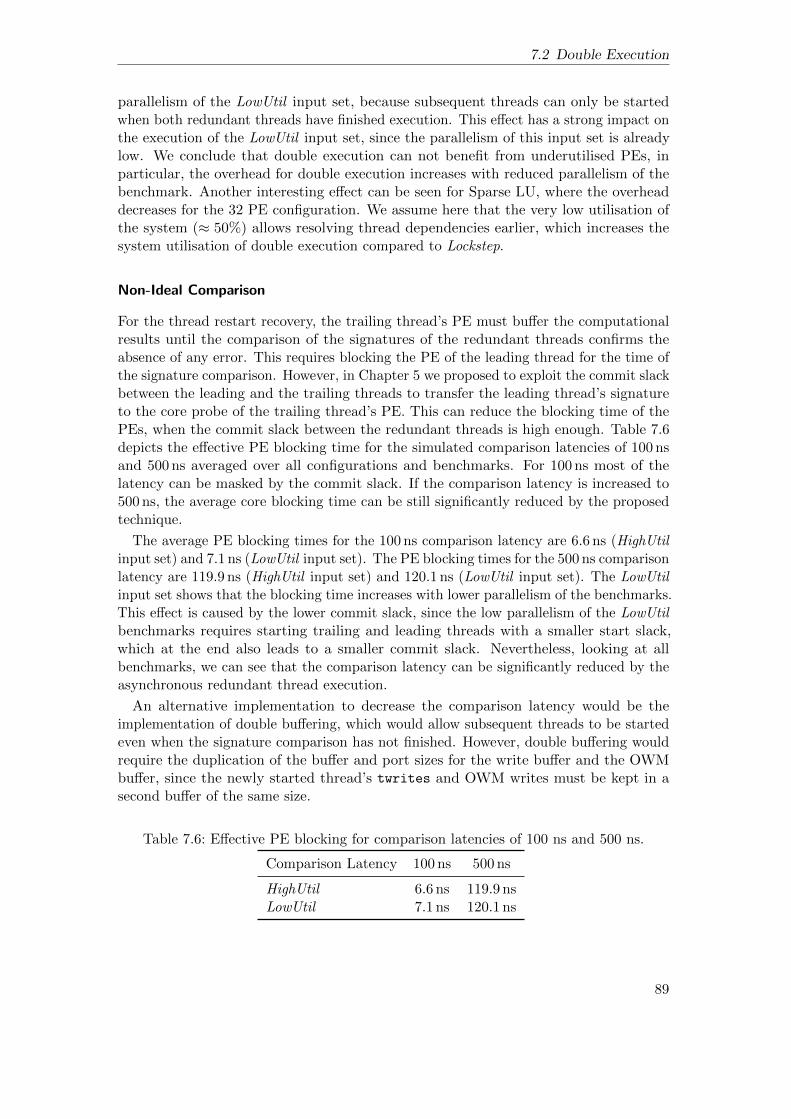
7.2 Double Execution
parallelism of the LowUtil input set, because subsequent threads can only be startedwhen both redundant threads have finished execution. This effect has a strong impact onthe execution of the LowUtil input set, since the parallelism of this input set is alreadylow. We conclude that double execution can not benefit from underutilised PEs, inparticular, the overhead for double execution increases with reduced parallelism of thebenchmark. Another interesting effect can be seen for Sparse LU, where the overheaddecreases for the 32 PE configuration. We assume here that the very low utilisation ofthe system (≈ 50%) allows resolving thread dependencies earlier, which increases thesystem utilisation of double execution compared to Lockstep.
Non-Ideal Comparison
For the thread restart recovery, the trailing thread’s PE must buffer the computationalresults until the comparison of the signatures of the redundant threads confirms theabsence of any error. This requires blocking the PE of the leading thread for the time ofthe signature comparison. However, in Chapter 5 we proposed to exploit the commit slackbetween the leading and the trailing threads to transfer the leading thread’s signatureto the core probe of the trailing thread’s PE. This can reduce the blocking time of thePEs, when the commit slack between the redundant threads is high enough. Table 7.6depicts the effective PE blocking time for the simulated comparison latencies of 100 nsand 500 ns averaged over all configurations and benchmarks. For 100 ns most of thelatency can be masked by the commit slack. If the comparison latency is increased to500 ns, the average core blocking time can be still significantly reduced by the proposedtechnique.
The average PE blocking times for the 100 ns comparison latency are 6.6 ns (HighUtilinput set) and 7.1 ns (LowUtil input set). The PE blocking times for the 500 ns comparisonlatency are 119.9 ns (HighUtil input set) and 120.1 ns (LowUtil input set). The LowUtilinput set shows that the blocking time increases with lower parallelism of the benchmarks.This effect is caused by the lower commit slack, since the low parallelism of the LowUtilbenchmarks requires starting trailing and leading threads with a smaller start slack,which at the end also leads to a smaller commit slack. Nevertheless, looking at allbenchmarks, we can see that the comparison latency can be significantly reduced by theasynchronous redundant thread execution.
An alternative implementation to decrease the comparison latency would be theimplementation of double buffering, which would allow subsequent threads to be startedeven when the signature comparison has not finished. However, double buffering wouldrequire the duplication of the buffer and port sizes for the write buffer and the OWMbuffer, since the newly started thread’s twrites and OWM writes must be kept in asecond buffer of the same size.
Table 7.6: Effective PE blocking for comparison latencies of 100 ns and 500 ns.
Comparison Latency 100 ns 500 ns
HighUtil 6.6 ns 119.9 nsLowUtil 7.1 ns 120.1 ns
89

7 Evaluation
0.8
0.9
1.0
1.1
2 4 8 16 32Processing Elements
Exec
utio
n tim
e no
rmal
ised
to L
ocks
tep
Latency 100 500
(a) HighUtil input set
0.8
0.9
1.0
1.1
2 4 8 16 32Processing Elements
Exec
utio
n tim
e no
rmal
ised
to L
ocks
tep
Latency 100 500
(b) LowUtil input set
Figure 7.5: Average execution time overhead for all benchmarks with comparison latenciesof 100 ns and 500 ns.
Figure 7.5 shows that the PE blocking has only a small impact on the execution timeof double execution. The average overhead for a comparison latency of 100 ns is notmeasurable in the simulator for the HighUtil input set and is 0.01% for the 500 ns latency.For the LowUtil input set, we found an overhead of 1.6% for a comparison latency of100 ns and 2.4% for a comparison latency of 500 ns.
7.2.2 Scalability
Figure 7.6 compares the speedup of double execution with the speedup of the non-redundant execution on half of the PEs. It can be seen that in the best case, the speedupof double execution is equal to the speedup of the non-redundant execution. While doubleexecution scales with the available PEs in the systems, we can also seen that doubleexecution can not speedup the execution compared to the non-redundant execution ofCholesky, Fibonacci, and Sparse LU. Only Matmul reveals a small speedup, because ofthe cache effects and its equal execution speed of the threads.
The reason for the decreasing speedup of the other benchmarks stems from the factthat subsequent threads can only be started, when the previous redundant threads havefinished execution and their signatures have been compared. This means that in the bestcase, the parallelism of the threads is equal to the non-redundant execution on half ofthe PEs. However, benchmarks with smaller parallelism reveal that the scalability ofdouble execution can be significantly reduced compared to the non-redundant execution.This can be observed for both input sets. On average the speedup of the HighUtil inputset is 5.8 for non-redundant and 5.7 for double execution, while for the LowUtil inputset, the speed up further decreases for double execution. The speed up for the LowUtilinput set is 5.1 for the non-redundant execution and 4.9 for the redundant execution.
90

7.2 Double Execution
Cholesky Fibonacci Matmul Sparse LU
124
8
16
1 2 4 8 16 32 1 2 4 8 16 32 1 2 4 8 16 32 1 2 4 8 16 32Processing Elements
Spee
dup
over
1 P
E sy
stem
Execution Type Double Execution Non−Redundant Execution(a) Scalability of non-redundant and double execution normalised to the non-redundant executionon one PE (HighUtil input set).
Cholesky Fibonacci Matmul Sparse LU
124
8
16
1 2 4 8 16 32 1 2 4 8 16 32 1 2 4 8 16 32 1 2 4 8 16 32Processing Elements
Spee
dup
over
1 P
E sy
stem
Execution Type Double Execution Non−Redundant Execution(b) Scalability non-redundant and double execution normalised to the non-redundant executionon one PE (LowUtil input set).
Figure 7.6: Scalability of non-redundant data-flow execution and double execution
7.2.3 Commit Slack
In contrast to Lockstep, double execution executes redundant threads completely de-coupled from each other. While this has advantages for the flexible resource usage andthe hardware implementation of double execution, it can also lead to asynchronousexecution of the redundant threads. The asynchronous execution can be used to maskthe comparison latency and exploit the leading thread as a prefetcher, however, it alsoincreases the error detection latency and reduces the parallelism of the application, sincesubsequent data-flow threads can be only started and errors detected, when both threadshave finished execution. Although the TSU prioritises waiting trailing threads overthe leading threads to reduce the commit slack, we found that the decoupled threadexecution can lead to a significant commit slack.
91
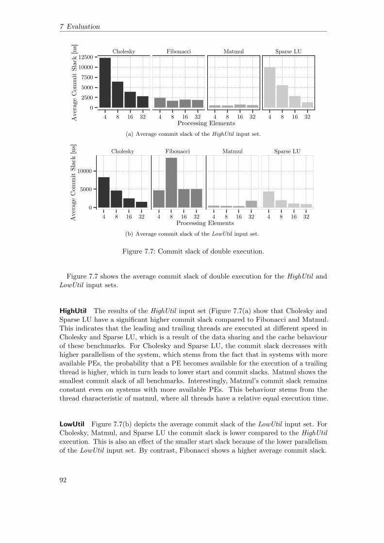
7 Evaluation
Cholesky Fibonacci Matmul Sparse LU
0250050007500
1000012500
4 8 16 32 4 8 16 32 4 8 16 32 4 8 16 32Processing ElementsA
vera
ge C
omm
it Sl
ack
[ns]
(a) Average commit slack of the HighUtil input set.
Cholesky Fibonacci Matmul Sparse LU
0
5000
10000
4 8 16 32 4 8 16 32 4 8 16 32 4 8 16 32Processing ElementsA
vera
ge C
omm
it Sl
ack
[ns]
(b) Average commit slack of the LowUtil input set.
Figure 7.7: Commit slack of double execution.
Figure 7.7 shows the average commit slack of double execution for the HighUtil andLowUtil input sets.
HighUtil The results of the HighUtil input set (Figure 7.7(a) show that Cholesky andSparse LU have a significant higher commit slack compared to Fibonacci and Matmul.This indicates that the leading and trailing threads are executed at different speed inCholesky and Sparse LU, which is a result of the data sharing and the cache behaviourof these benchmarks. For Cholesky and Sparse LU, the commit slack decreases withhigher parallelism of the system, which stems from the fact that in systems with moreavailable PEs, the probability that a PE becomes available for the execution of a trailingthread is higher, which in turn leads to lower start and commit slacks. Matmul shows thesmallest commit slack of all benchmarks. Interestingly, Matmul’s commit slack remainsconstant even on systems with more available PEs. This behaviour stems from thethread characteristic of matmul, where all threads have a relative equal execution time.
LowUtil Figure 7.7(b) depicts the average commit slack of the LowUtil input set. ForCholesky, Matmul, and Sparse LU the commit slack is lower compared to the HighUtilexecution. This is also an effect of the smaller start slack because of the lower parallelismof the LowUtil input set. By contrast, Fibonacci shows a higher average commit slack.
92

7.2 Double Execution
The commit slack of Fibonacci is strongly run time depended, which is caused bydiffering scheduling decisions of the TSU scheduler in the different system configurations.For Matmul and Sparse LU, the evaluation reveals a decreasing commit slack for largersystem configuration, which is a consequence of the lower parallelism of the LowUtilinput set.
7.2.4 Graceful Degradation under Permanent Faults
In order to evaluate the ability of the proposed mechanisms to cope with permanentfaulty PEs, we simulated the baseline configuration with a certain number of deactivatedPEs, as described in Section 7.1.4.
HighUtil The Figures 7.8 (4 and 8 PE system) and 7.9 (16 and 32 PE system) showthe execution time of double execution normalised to the execution time on a non-faulty system, when 0–8 PEs are permanently deactivated. The figures depict onlyconfigurations, which are still functional and exclude configurations, which have nofunctional PEs left. Compared to systems without deactivated PEs, we can see that thesystems’ performance gracefully degrades with the number of the deactivated PEs. Inparticular, for system configurations with 16–32 PEs, double execution is flexible enoughto compensate even higher numbers of permanent faulty PEs.
LowUtil Figure 7.10 (4 and 8 PE system) and 7.11 (16 and 32 PE system) depict thegraceful degradation of double execution, when 0–8 PEs are permanently faulty forthe LowUtil input set. Compared to the HighUtil input set, the systems can bettercompensate the deactivated PEs, since the benchmarks can not fully utilise all PEs, asthe evaluation of the scalability of double execution has shown before and therefore thelost performance by the deactivated PEs has a smaller performance impact. In particular,this effect can be seen for the 32 PE configuration executing Fibonacci and Sparse LU.Due to the limited parallelism of both benchmarks, several PEs can be deactivatedwithout performance impact. In both cases, the underutilised PEs serve as flexible sparePEs and can be used without significant performance impact.
Nevertheless, for both input sets the execution time of double execution gracefullydegrades even when multiple PEs of a system are deactivated. We conclude that doubleexecution can exploit all functional PEs of a system, even when some PEs are permanentlydeactivated and can gracefully reduce the performance of the system, while being stilloperational.
93

7 Evaluation
Cholesky
Fibonacci
Matmul
Sparse LU
12345678
12345678
12345678
12345678
4 8
4 8
4 8
4 8Processing Elements
Exec
utio
n tim
e no
rmal
ised
to fa
ult−
free
exec
utio
n
Faulty 0 1 2 3 4 5 6 7
Figure 7.8: Graceful degradation of double execution, when 0–7 PEs are permanentlyfaulty in the 4 and 8 PE systems (HighUtil).
94

7.2 Double Execution
Cholesky
Fibonacci
Matmul
Sparse LU
1.0
1.5
2.0
1.0
1.5
2.0
1.0
1.5
2.0
1.0
1.5
2.0
16 32
16 32
16 32
16 32Processing Elements
Exec
utio
n tim
e no
rmal
ised
to fa
ult−
free
exec
utio
n
Faulty 0 1 2 3 4 5 6 7 8
Figure 7.9: Graceful degradation of double execution, when 0–8 PEs are permanentlyfaulty in the 16 and 32 PE systems (HighUtil).
95
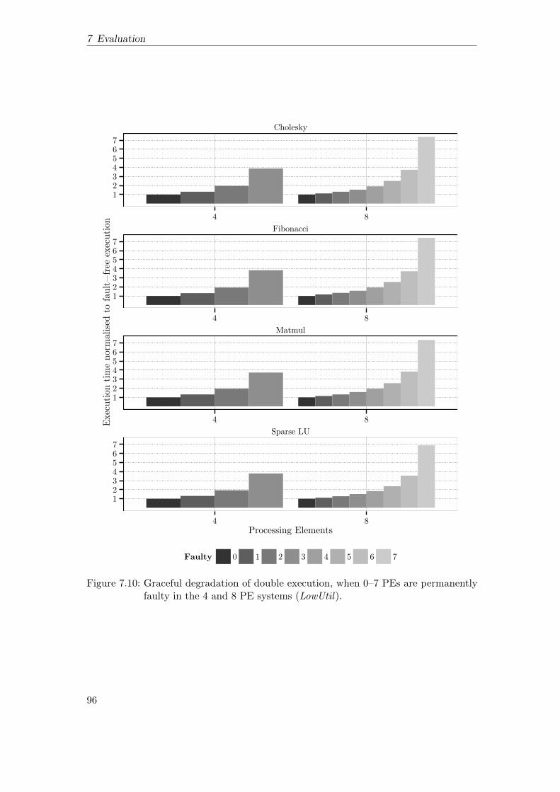
7 Evaluation
Cholesky
Fibonacci
Matmul
Sparse LU
1234567
1234567
1234567
1234567
4 8
4 8
4 8
4 8Processing Elements
Exec
utio
n tim
e no
rmal
ised
to fa
ult−
free
exec
utio
n
Faulty 0 1 2 3 4 5 6 7
Figure 7.10: Graceful degradation of double execution, when 0–7 PEs are permanentlyfaulty in the 4 and 8 PE systems (LowUtil).
96

7.2 Double Execution
Cholesky
Fibonacci
Matmul
Sparse LU
1.0
1.5
2.0
1.0
1.5
2.0
1.0
1.5
2.0
1.0
1.5
2.0
16 32
16 32
16 32
16 32Processing Elements
Exec
utio
n tim
e no
rmal
ised
to fa
ult−
free
exec
utio
n
Faulty 0 1 2 3 4 5 6 7 8
Figure 7.11: Graceful degradation of double execution, when 0–8 PEs are permanentlyfaulty in the 16 and 32 PE systems (LowUtil).
97

7 Evaluation
7.2.5 Execution Overhead under Transient Faults
Since thread restart recovery promises low-overhead recovery, we also evaluate theexecution overhead with transient faults. We inject faults at a fixed time interval of105 ns. After a fixed amount of faults, the system stops the injection and proceedswithout faults. We investigate the impact of 5 and 10 faults on the simulated systemconfigurations.
The results for the HighUtil shown in Figure 7.12, depict that thread restart recoveryhas a negligible effect on the execution time of double execution in case of transientfaults. This is not surprising, since in case of the HighUtil input set, the benchmarksexecute several thousand threads.
Cholesky Fibonacci
Matmul Sparse LU0.90
0.95
1.00
1.05
1.10
0.90
0.95
1.00
1.05
1.10
2 4 8 16 32 2 4 8 16 32Processing ElementsEx
ecut
ion
time
norm
alise
d to
faul
t−fre
e do
uble
exec
.
Transient Faults 5 10
Figure 7.12: Execution time of double execution normalised to double execution withoutfaults, when 5 and 10 faults occur (HighUtil).
By contrast, the evaluation of the LowUtil input set, depicted in Figure 7.13, shows ameasurable impact of the thread restart recovery, since for the LowUtil input set thebenchmark execute a significant smaller number of data-flow threads, which in turnincreases the relative execution time overhead for a thread restart. In particular, theFibonacci benchmark, which executes only 68 threads in case of the LowUtil inputset, suffers from a significant overhead, in particular when 10 threads are restarted.Nevertheless, we conclude that thread restarts can be used for efficient recovery, evenunder the occurrence of multiple faults.
98
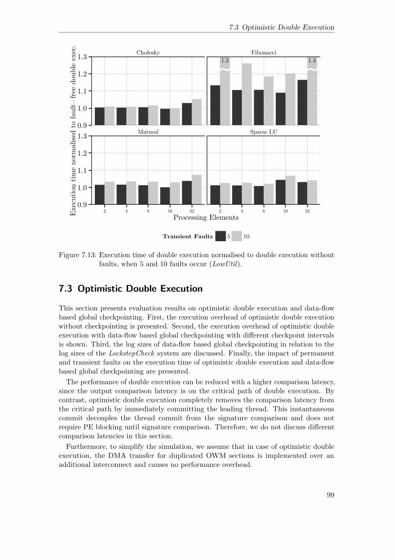
7.3 Optimistic Double Execution
Cholesky Fibonacci
Matmul Sparse LU0.9
1.0
1.1
1.2
1.3
0.9
1.0
1.1
1.2
1.3
2 4 8 16 32 2 4 8 16 32
Processing Elements
Exec
ution t
ime
norm
alise
d t
o fault−
free
double
exec
.
Transient Faults 5 10
1.41.3
~ ~
Figure 7.13: Execution time of double execution normalised to double execution withoutfaults, when 5 and 10 faults occur (LowUtil).
7.3 Optimistic Double Execution
This section presents evaluation results on optimistic double execution and data-flowbased global checkpointing. First, the execution overhead of optimistic double executionwithout checkpointing is presented. Second, the execution overhead of optimistic doubleexecution with data-flow based global checkpointing with different checkpoint intervalsis shown. Third, the log sizes of data-flow based global checkpointing in relation to thelog sizes of the LockstepCheck system are discussed. Finally, the impact of permanentand transient faults on the execution time of optimistic double execution and data-flowbased global checkpointing are presented.
The performance of double execution can be reduced with a higher comparison latency,since the output comparison latency is on the critical path of double execution. Bycontrast, optimistic double execution completely removes the comparison latency fromthe critical path by immediately committing the leading thread. This instantaneouscommit decouples the thread commit from the signature comparison and does notrequire PE blocking until signature comparison. Therefore, we do not discuss differentcomparison latencies in this section.
Furthermore, to simplify the simulation, we assume that in case of optimistic doubleexecution, the DMA transfer for duplicated OWM sections is implemented over anadditional interconnect and causes no performance overhead.
99
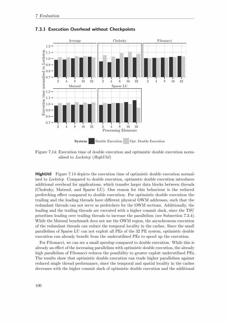
7 Evaluation
7.3.1 Execution Overhead without Checkpoints
Average Cholesky Fibonacci
Matmul Sparse LU
0.70.80.91.01.11.2
0.70.80.91.01.11.2
2 4 8 16 32 2 4 8 16 32 2 4 8 16 32
2 4 8 16 32 2 4 8 16 32Processing Elements
Exec
utio
n tim
e no
rmal
ised
to L
ocks
tep
System Double Execution Opt. Double Execution
Figure 7.14: Execution time of double execution and optimistic double execution norm-alised to Lockstep (HighUtil)
HighUtil Figure 7.14 depicts the execution time of optimistic double execution normal-ised to Lockstep. Compared to double execution, optimistic double execution introducesadditional overhead for applications, which transfer larger data blocks between threads(Cholesky, Matmul, and Sparse LU). One reason for this behaviour is the reducedprefetching effect compared to double execution. For optimistic double execution thetrailing and the leading threads have different physical OWM addresses, such that theredundant threads can not serve as prefetchers for the OWM sections. Additionally, theleading and the trailing threads are executed with a higher commit slack, since the TSUprioritises leading over trailing threads to increase the parallelism (see Subsection 7.3.4).While the Matmul benchmark does not use the OWM region, the asynchronous executionof the redundant threads can reduce the temporal locality in the caches. Since the smallparallelism of Sparse LU can not exploit all PEs of the 32 PE system, optimistic doubleexecution can already benefit from the underutilised PEs to speed up the execution.
For Fibonacci, we can see a small speedup compared to double execution. While this isalready an effect of the increasing parallelism with optimistic double execution, the alreadyhigh parallelism of Fibonacci reduces the possibility to greater exploit underutilised PEs.The results show that optimistic double execution can trade higher parallelism againstreduced single thread performance, since the temporal and spatial locality in the cachesdecreases with the higher commit slack of optimistic double execution and the additional
100

7.3 Optimistic Double Execution
costs for the OWM address mapping. However, in case of the HighUtil input set,which provides enough parallelism to utilise all system configurations, optimistic doubleexecution leads to increasing execution time. This overhead is evident for benchmarks,which benefit from prefetching effects in double execution.
Average Cholesky Fibonacci
Matmul Sparse LU
0.70.80.91.01.11.2
0.70.80.91.01.11.2
2 4 8 16 32 2 4 8 16 32 2 4 8 16 32
2 4 8 16 32 2 4 8 16 32Processing Elements
Exec
utio
n tim
e no
rmal
ised
to L
ocks
tep
System Double Execution Opt. Double Execution
Figure 7.15: Execution time of double execution and optimistic double execution norm-alised to Lockstep (LowUtil)
LowUtil The LowUtil input set, depicted in Figure 7.15, shows the capability ofoptimistic double execution to exploit underutilised resources to speed up the redundantexecution. Optimistic double execution exploits the effect that all thread dependencieshave already been resolved, when the redundant threads are moved to the RQ. Thismeans that all trailing threads can be executed in parallel, since their dependencies havealready been resolved and the inputs are available for execution. The evaluation of theLowUtil input set reveals that all benchmarks can better utilise the available PEs. Thebest speedup compared to Lockstep is seen for Fibonacci, which is ≈ 25% faster thanLockstep and ≈ 28% faster than double execution. Another interesting effect can be seenfor Sparse LU. While the execution time of optimistic double execution for Sparse LU isdecreasing until 16 PEs, the execution times of optimistic double execution and doubleexecution for the 32 PE system are relatively equal. This effect results from the verylow parallelism of Sparse LU for the LowUtil input set, which means that the utilisationof the system is low enough such that scheduling decisions for both double executionvariants are quite similar, leading to the same overhead. For the 32 PE system, theLowUtil input set is executed ≈ 8% faster than Lockstep and ≈ 15% faster than doubleexecution on average.
101

7 Evaluation
7.3.2 Scalability
Figure 7.16(a) depicts the scalability of optimistic double execution for the HighUtilinput set. Optimistic double execution can increase the parallelism of double executionand benefits from underutilised PEs. This is particular the case for the LowUtil inputset with its lower parallelism. Compared to the non-redundant execution on half of thePEs, we can see that the scalability of optimistic double execution is relatively similarto double execution. However, when the utilisation of the system decreases, which isthe case for the 32 PE system executing Sparse LU, the speedup of optimistic doubleexecution exceeds the non-redundant execution. This shows that optimistic doubleexecution can exploit underutilised PEs in the system to speed up redundant threadexecution.
Cholesky Fibonacci Matmul Sparse LU
124
8
1 2 4 8 16 32 1 2 4 8 16 32 1 2 4 8 16 32 1 2 4 8 16 32Processing Elements
Spee
dup
over
1 P
E sy
stem
Execution Type Non−Redundant Execution Opt. Double Execution(a) Scalability of non-redundant and optimistic double execution in relation to the non-redundantexecution on one PE (HighUtil input set).
Cholesky Fibonacci Matmul Sparse LU
124
8
16
1 2 4 8 16 32 1 2 4 8 16 32 1 2 4 8 16 32 1 2 4 8 16 32Processing Elements
Spee
dup
over
1 P
E sy
stem
Execution Type Non−Redundant Execution Opt. Double Execution(b) Scalability of non-redundant and optimistic double execution in relation to the non-redundantexecution on one PE (LowUtil input set).
Figure 7.16: Scalability of non-redundant execution and optimistic double execution.
102

7.3 Optimistic Double Execution
Figure 7.16(b) shows that this effect increases for the LowUtil input set with itslower parallelism. Especially Cholesky, Fibonacci, and Matmul reveal an increasingspeedup, when the parallelism of the benchmarks can not utilise all PEs of the system.Sparse LU achieves also a speedup compared to the non-redundant execution for systemconfigurations up to 16 PEs. However, for the 32 PE system the speedup saturates. Asexplained before, this effect is a result of the very low utilisation of Sparse LU.
7.3.3 Execution Overhead with Checkpoints
Section 7.3.1 presented results of optimistic double execution without checkpointing.However, optimistic double execution can not recover from errors without a checkpointmechanism. In this subsection, the evaluation results of optimistic double executionwith the data-flow based global checkpointing are presented. The results of optimisticdouble execution with checkpointing are compared with LockstepCheck, which alwayscreates the same number of checkpoints as the data-flow based checkpointing mechanism.As mentioned before, we assume a static overhead per checkpoint for LockstepCheck of0.1 µs.
HighUtil Figure 7.17 shows the execution time overhead of optimistic double executionwith checkpoint intervals of 10 000 ns, 100 000 ns and 1 000 000 ns for the HighUtil inputset. At these intervals, the checkpoint creation is triggered. However, when a checkpointis triggered, all unverified, already committed leading threads must be checked for errorsbefore the new checkpoint can be established. When a checkpoint is triggered, the TSUscheduler prioritises the currently waiting trailing threads to establish the checkpointas fast as possible. As a consequence, the checkpointing interval influences also thecommit slack between the leading and trailing threads (see Subsection 7.3.4). Theresults show that checkpoint creation introduces only a small overhead compared to theexecution without checkpoints for the HighUtil input set and can be reduced with longercheckpoint intervals, as seen for Sparse and Cholesky. Compared to LockstepCheck wefound that optimistic double execution has performance advantages for smaller checkpointintervals. Interestingly, Matmul is executed faster with checkpoint intervals of 10 000 nsand 100 000 ns. This behaviour results from the reduced asynchronous execution betweenthe leading and the trailing threads.
LowUtil Figure 7.18 depicts the execution time of optimistic double execution for theLowUtil input set. Compared to the HighUtil input set, checkpointing has a strongerinfluence on the execution time. For Cholesky and Fibonacci the execution time ofoptimistic double execution can be significantly increased by the checkpoint creationoverhead, eliminating the speedup of optimistic double execution. In case of Choleskyand Fibonacci, the overhead is induced by the low parallelism of the benchmarks andtherefore underutilisation of the PEs, while waiting for new checkpoints to be established.For all benchmarks, the overhead induced by the checkpoint creation is reduced withlonger checkpoint intervals. However, Cholesky, Matmul, and Sparse LU are still fasterthan LockstepCheck for the 10 000 ns and 100 000 ns checkpoint intervals.
103

7 Evaluation
LockstepCheck Opt. Double Execution
0.8
1.0
1.2
0.8
1.0
1.2
0.8
1.0
1.2
0.8
1.0
1.2
CholeskyFibonacci
Matm
ulSparse LU
2 4 8 16 32 2 4 8 16 32Processing Elements
Exec
utio
n tim
e no
rmal
ised
to L
ocks
tep
System
LockstepCheck (10,000)LockstepCheck (100,000)LockstepCheck (1,000,000)Opt. Double Execution (0)Opt. Double Execution (10,000)Opt. Double Execution (100,000)Opt. Double Execution (1,000,000)
Figure 7.17: Execution time of LockstepCheck and optimistic double execution normalisedto Lockstep (HighUtil).
104

7.3 Optimistic Double Execution
LockstepCheck Opt. Double Execution
0.8
1.0
1.2
0.8
1.0
1.2
0.8
1.0
1.2
0.8
1.0
1.2
CholeskyFibonacci
Matm
ulSparse LU
2 4 8 16 32 2 4 8 16 32Processing Elements
Exec
utio
n tim
e no
rmal
ised
to L
ocks
tep
System
LockstepCheck (10,000)LockstepCheck (100,000)LockstepCheck (1,000,000)Opt. Double Execution (0)Opt. Double Execution (10,000)Opt. Double Execution (100,000)Opt. Double Execution (1,000,000)
Figure 7.18: Execution time of LockstepCheck and optimistic double execution normalisedto Lockstep (LowUtil).
105
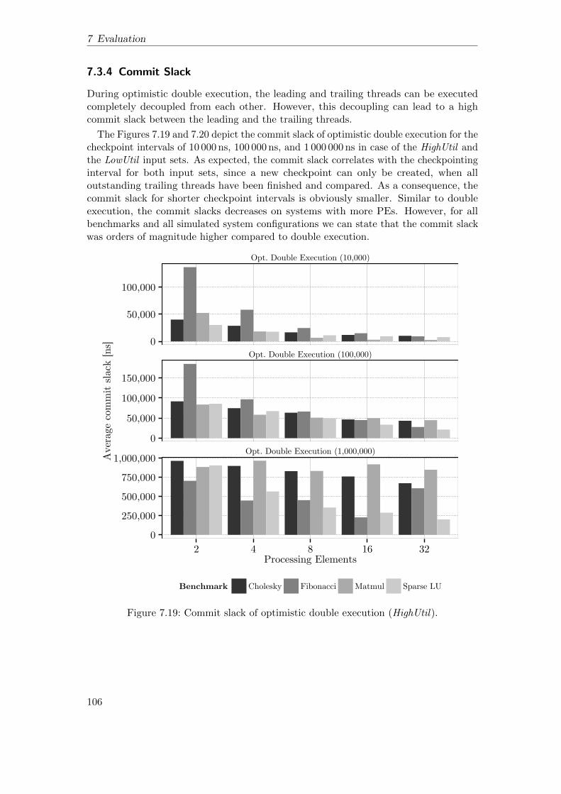
7 Evaluation
7.3.4 Commit Slack
During optimistic double execution, the leading and trailing threads can be executedcompletely decoupled from each other. However, this decoupling can lead to a highcommit slack between the leading and the trailing threads.
The Figures 7.19 and 7.20 depict the commit slack of optimistic double execution for thecheckpoint intervals of 10 000 ns, 100 000 ns, and 1 000 000 ns in case of the HighUtil andthe LowUtil input sets. As expected, the commit slack correlates with the checkpointinginterval for both input sets, since a new checkpoint can only be created, when alloutstanding trailing threads have been finished and compared. As a consequence, thecommit slack for shorter checkpoint intervals is obviously smaller. Similar to doubleexecution, the commit slacks decreases on systems with more PEs. However, for allbenchmarks and all simulated system configurations we can state that the commit slackwas orders of magnitude higher compared to double execution.
Opt. Double Execution (10,000)
Opt. Double Execution (100,000)
Opt. Double Execution (1,000,000)
0
50,000
100,000
0
50,000
100,000
150,000
0
250,000
500,000
750,000
1,000,000
2 4 8 16 32Processing Elements
Ave
rage
com
mit
slack
[ns]
Benchmark Cholesky Fibonacci Matmul Sparse LU
Figure 7.19: Commit slack of optimistic double execution (HighUtil).
106
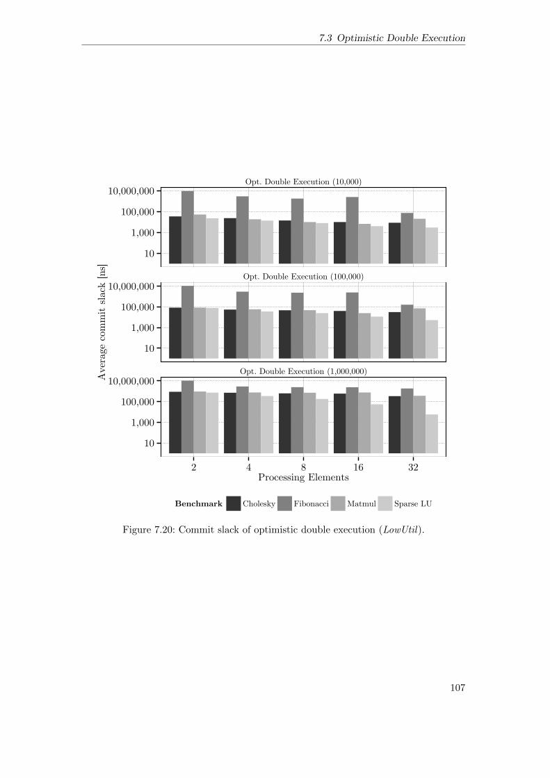
7.3 Optimistic Double Execution
Opt. Double Execution (10,000)
Opt. Double Execution (100,000)
Opt. Double Execution (1,000,000)
10
1,000
100,000
10,000,000
10
1,000
100,000
10,000,000
10
1,000
100,000
10,000,000
2 4 8 16 32Processing Elements
Aver
age
com
mit s
lack
[ns]
Benchmark Cholesky Fibonacci Matmul Sparse LU
Figure 7.20: Commit slack of optimistic double execution (LowUtil).
107

7 Evaluation
7.3.5 Log Size of Global Checkpoints
Data-flow based checkpointing can reduce the necessary memory log size, since onlythe thread frame region and the OWM region must be incorporated in the log. Thisrepresents a significant advantage over non-data-flow checkpointing, like LockstepCheck,which requires logging of all changes to the main memory. The Figures 7.21 and 7.22depict the average log size of the data-flow based checkpointing normalised to the averagelog size of LockstepCheck. It can be seen that data-flow based checkpointing reducesthe log size requirements for both input sets to only a small fraction compared toLockstepCheck. We assume that the increasing normalised log size for larger systemsstems from the fact that the data-flow based logging does not use the caches, whileLockstepCheck creates only new log entries, when data is written back to the mainmemory. However, the cache size and therefore the storage capabilities of the cachesincreases with more PEs.
Cholesky Fibonacci Matmul Sparse LU
0.00
0.05
0.10
0.15
2 4 8 16 32 2 4 8 16 32 2 4 8 16 32 2 4 8 16 32Processing Elements
Avg
. Log
size
nor
mal
ised
to L
ocks
tepC
heck
Figure 7.21: Average log size per checkpoint normalised to the log size of LockstepCheck(HighUtil).
Cholesky Fibonacci Matmul Sparse LU
0.00
0.05
0.10
0.15
0.20
2 4 8 16 32 2 4 8 16 32 2 4 8 16 32 2 4 8 16 32Processing Elements
Avg
. Log
size
nor
mal
ised
to L
ocks
tepC
heck
Figure 7.22: Average log size per checkpoint normalised to the log size of LockstepCheck(LowUtil).
108

7.3 Optimistic Double Execution
7.3.6 Graceful Degradation under Permanent Faults
The Figures 7.23, 7.24, 7.25, and 7.26 depict the impact of permanent faults on theexecution time of optimistic double execution for the HighUtil and LowUtil input sets.The simulation uses a checkpoint interval of 10 000 ns. Similar to double execution,optimistic double execution can compensate permanent broken PEs and gracefully adaptits performance in case of permanent faulty PEs for all simulated system configurations.
Cholesky
Fibonacci
Matmul
Sparse LU
12345678
12345678
12345678
12345678
4 8
4 8
4 8
4 8Processing Elements
Exec
utio
n tim
e no
rmal
ised
to fa
ult−
free
exec
utio
n
Faulty 0 1 2 3 4 5 6 7
Figure 7.23: Graceful degradation of optimistic double execution, when 0–7 PEs arepermanent faulty in the 4 and 8 PE systems (HighUtil).
109

7 Evaluation
Cholesky
Fibonacci
Matmul
Sparse LU
1.0
1.5
2.0
1.0
1.5
2.0
1.0
1.5
2.0
1.0
1.5
2.0
16 32
16 32
16 32
16 32Processing Elements
Exec
utio
n tim
e no
rmal
ised
to fa
ult−
free
exec
utio
n
Faulty 0 1 2 3 4 5 6 7 8
Figure 7.24: Graceful degradation of optimistic double execution, when 0–8 PEs arepermanent faulty in the 8 to 16 PE systems (HighUtil).
110

7.3 Optimistic Double Execution
Cholesky
Fibonacci
Matmul
Sparse LU
1234567
1234567
1234567
1234567
4 8
4 8
4 8
4 8Processing Elements
Exec
ution t
ime
norm
alise
d t
o fault−
free
exec
ution
Faulty 0 1 2 3 4 5 6 7
Figure 7.25: Graceful degradation of optimistic double execution, when 0–7 PEs arepermanent faulty in the 4 and 8 PE systems (LowUtil).
111

7 Evaluation
Cholesky
Fibonacci
Matmul
Sparse LU
1.0
1.5
2.0
1.0
1.5
2.0
1.0
1.5
2.0
1.0
1.5
2.0
16 32
16 32
16 32
16 32Processing Elements
Exec
ution t
ime
norm
alise
d t
o fault−
free
exec
ution
Faulty 0 1 2 3 4 5 6 7 8
Figure 7.26: Graceful degradation of optimistic double execution, when 0–8 PEs arepermanent faulty in the 16 and 32 PE systems (LowUtil).
112
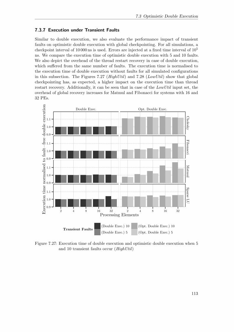
7.3 Optimistic Double Execution
7.3.7 Execution under Transient Faults
Similar to double execution, we also evaluate the performance impact of transientfaults on optimistic double execution with global checkpointing. For all simulations, acheckpoint interval of 10 000 ns is used. Errors are injected at a fixed time interval of 105
ns. We compare the execution time of optimistic double execution with 5 and 10 faults.We also depict the overhead of the thread restart recovery in case of double execution,which suffered from the same number of faults. The execution time is normalised tothe execution time of double execution without faults for all simulated configurationsin this subsection. The Figures 7.27 (HighUtil) and 7.28 (LowUtil) show that globalcheckpointing has, as expected, a higher impact on the execution time than threadrestart recovery. Additionally, it can be seen that in case of the LowUtil input set, theoverhead of global recovery increases for Matmul and Fibonacci for systems with 16 and32 PEs.
Double Exec. Opt. Double Exec.
0.9
1.0
1.1
0.9
1.0
1.1
0.9
1.0
1.1
0.9
1.0
1.1
CholeskyFibonacci
Matm
ulSparse LU
2 4 8 16 32 2 4 8 16 32Processing ElementsEx
ecut
ion
time
norm
alise
d to
faul
t−fre
e do
uble
exec
utio
n
Transient Faults(Double Exec.) 10 (Double Exec.) 5
(Opt. Double Exec.) 10 (Opt. Double Exec.) 5
Figure 7.27: Execution time of double execution and optimistic double execution when 5and 10 transient faults occur (HighUtil)
113

7 Evaluation
Double Exec. Opt. Double Exec.
1.001.251.501.752.00
1.001.251.501.752.00
1.001.251.501.752.00
1.001.251.501.752.00
Cholesk
yFib
onacci
Matm
ul
Sparse L
U
2 4 8 16 32 2 4 8 16 32Processing Elements
Exec
ution
tim
e nor
mal
ised
to
fault−
free
dou
ble
exec
ution
Transient Faults(Double Exec.) 10
(Double Exec.) 5
(Opt. Double Exec.) 10
(Opt. Double Exec.) 5
~ ~~~~
~
2.5 3.9 2.5 3.56.4
2.0
Figure 7.28: Execution time of double execution and optimistic double execution when 5and 10 transient faults occur (LowUtil).
114
7.4 Summary
7.4 Summary
This section presented evaluation results of double execution, thread restart recovery,optimistic double execution, and data-flow based global checkpointing. The proposedmechanisms were integrated in the COTSon multi-core simulator and evaluated withfour data-flow benchmarks.
Compared with an ideal lockstep machine, double execution induces only a smalloverhead for systems with 16–32 PEs and is faster for the 2–8 PE systems. The impact ofthe comparison latency on double execution can be significantly reduced by the commitslack of the redundant threads, such that even a high comparison latency of 500 ns showsonly a small execution time overhead. Furthermore, the evaluation results confirmedthat double execution can not efficiently exploit underutilised PEs to speed up theredundant execution. While this does not lead to a significant overhead for the HighUtilbenchmarks, the LowUtil input set suffers from a significant overhead compared to theideal lockstep system. It was also shown that double execution can induce a significantcommit slack, leading to a high error detection latency in the worst case. Nevertheless,the evaluation also reveals that the commit slack can be decreased for larger systemswith more available PEs. The evaluation of the system behaviour under permanent faultsconfirms that double execution systems are able to gracefully adapt their performance,even when an uneven number of PEs is permanently broken. Furthermore, the evaluationof double execution and thread restart recovery under transient faults reveals that threadrestart recovery has only a small impact on the execution time of double execution, evenwhen up to 10 transient faults occur.
The evaluation of optimistic double execution without global checkpoint creationshowed that the OWM replication and asynchronous execution of the redundant threadscan lead to overhead. In particular for the HighUtil input set, where optimistic doubleexecution can not exploit underutilised PEs to speed up the redundant execution, wefound a significant overhead compared to double execution. However, for the LowUtilinput, the execution of optimistic double execution achieves a significant speedup. Thisperformance advantage stems from the higher parallelism of the optimistic doubleexecution. It was further shown that optimistic double execution improves the scalabilityof the redundant thread execution and is able to speed up the execution over thenon-redundant execution by exploiting underutilised PEs. This finding is of particularinterest for future parallel systems which may host more PEs than the simulated systemconfigurations used in thesis. However, the simulation of optimistic double executionwith global checkpointing also showed that the checkpoint creation overhead reducesthe execution time advantages for some benchmarks. Furthermore, the commit slackof optimistic double execution is significant higher compared to double execution andstrongly influenced by the checkpoint interval, since all unverified data-flow threads mustbe compared before a new checkpoint can be established. Compared to the ideal lockstepmachine with conventional checkpointing, we still found execution time advantagesof optimistic double execution and data-flow based checkpointing for relatively shortcheckpoint intervals. Additionally, the memory log size can be significantly reduced bythe data-flow based global checkpointing mechanism, since not all memory accesses mustbe incorporated in the log during a checkpoint. Similar to double execution, optimisticdouble execution is also able to gracefully adjust its performance, when multiple PEs
115

7 Evaluation
are permanently faulty. However, under the occurrence of transient faults, the overheadof the global recovery mechanism is significantly higher compared to the thread restartrecovery.
116

8Summary and Future Work
This chapter summarises the results of this thesis and presents ideas on future work ondata-flow based fault-tolerant execution.
8.1 Summary
This thesis presented fault-detection, recovery, and diagnosis techniques for a coarse-grained, threaded data-flow execution model to support scalable fault-tolerance in amulti-core architecture. Double execution, the loosely-coupled redundant execution ofdata-flow threads was integrated in the baseline data-flow execution model and data-flow specific solutions for input replication, output comparison, and redundant threadmanagement were described in detail.
Based on double execution, a thread restart mechanism was proposed, which requiresthat redundant data-flow threads can only commit, when their results have been compared.Double execution and thread restart recovery were used to implement a fault diagnosismechanism to localise and identify permanent faulty processing elements in the system.The fault detection unit keeps track of detected PE errors and is able to localise faultyPEs by majority voting. In case of a permanent or intermittent fault, double executionand thread restart recovery support the shutdown of multiple PEs and are able togracefully reduce the performance of the system, even when multiple PEs must bedeactivated.
It was further shown that the data-flow execution principle, leveraged by doubleexecution and thread restart recovery, has several advantages for the implementationof redundant execution, since result comparison is only necessary for data which isconsumed by subsequent data-flow threads. Additionally, redundant data-flow threadscan be executed completely decoupled from each other, which allows to re-use thedata-flow thread scheduler to manage the redundant thread execution. Finally, inputreplication, output comparison, and the synchronisation between redundant threads issimplified by the data-flow execution principle.
To increase the parallelism of the redundant thread execution, an optimistic variant ofdouble execution was presented, which speculatively allows succeeding data-flow threads
117

8 Summary and Future Work
to be started before the result comparison has verified the correctness of the threadexecution. This allows the leading thread to make forward progress, while the datadependencies between the trailing threads have already been resolved by the leadingthreads. However, the speculative thread commit requires a mechanism to guaranteeinput replication for OWM regions. The proposed solution for input replication of theOWM memory uses DMA transfers to copy the OWM sections of the leading threadbefore the OWM region is required by the trailing thread.
Since optimistic double execution allows committing unverified and potentially erro-neous results, the thread restart mechanism can not be used for recovery with optimisticdouble execution. Therefore, a data-flow based global recovery mechanism was proposed.In case of global checkpointing, the data-flow execution principle reduces the checkpointcreation effort, since the valid execution state of the system is only stored in the mainmemory and the TSU, while the execution contexts of the PEs can be considered asunsafe, recoverable state. This reduces the checkpointing costs, since for checkpointcreation, only the TSU state and a log, incorporating the thread frame and the OWMregion, are required. Compared to checkpointing solutions for shared memory multi-cores,like [Sorin et al., 2002; Prvulovic et al., 2002], this can reduce the checkpointing com-plexity, since no architectural contexts of the PEs, the cache states, and the coherenceprotocol must be checkpointed or recovered.
Finally, the evaluation results of the proposed fault-tolerance mechanism showed thatdouble execution has only a small overhead compared to an ideal lockstep system, whilethe execution is even faster for some system configurations and benchmarks. Particularly,benchmarks, which take advantages of the shared TF and OWM region between theredundant threads achieve a speedup compared to the ideal lockstep execution. Doubleexecution has very low overhead when transient faults occur and is able to gracefullyadapt its execution speed, when multiple PEs are deactivated due to permanent faults.However, double execution shows also limited scalability compared to the non-redundantexecution, which reduces the exploitation of underutilised PEs. Compared to doubleexecution, optimistic double execution shows a significant overhead for applications withhigh parallelism, but can speed up the execution of benchmarks, which are not able tofully utilise all PEs. The global checkpointing required for optimistic double executionleads to additional overhead for the periodic checkpoint creation and exposes increasingexecution time when transient faults occur. Nevertheless, compared to a conventionalcheckpointing scheme for a shared memory multi-core, optimistic double execution anddata-flow based checkpointing show still reasonable overhead, in particular, for shortercheckpoint intervals.
Finally, we conclude that the data-flow based fault-tolerance mechanisms presentedin this thesis support the integration of flexible and scalable redundant execution andcheckpointing mechanisms in a parallel architecture. In particular, the loosely-coupledexecution of data-flow threads does not require strict cycle-by-cycle synchronisation andtherefore allows the use of complex out-of-order cores and shared resources betweenthe redundant execution units. Furthermore, the redundant threads can be executeddecoupled from each other, improving the flexible resource sharing in a multi-corearchitecture. We think that the advantages of the data-flow execution principle for theconstruction of redundant execution and checkpointing mechanisms can help to solvereliability issues in future massively parallel architectures.
118

8.2 Future Work
8.2 Future Work
This section discusses possible future research ideas and applications of the data-flowbased fault tolerance mechanisms presented in this thesis.
Although fault-tolerance mechanism are state-of-the-art for safety-critical systems,most commercial fault-tolerant techniques in the embedded domain focus on lockstepexecution of sequential applications [Infineon Technologies AG, 2015; STMicroelectronics,2014]. However, future advanced embedded applications, like advanced driver assistancesystems (ADAS) or autonomous driving, require high computational performance. Whilethis performance can be usually satisfied by parallel applications and embedded multi-core systems, the systems must also give safety guarantees, such that hardware faults donot lead to a catastrophic behaviour of the system. This means that the fault detectionand recovery mechanisms proposed in this thesis may also be used for the implementationof high-performance safety-critical systems. However, functional safety does not onlydemand fault-tolerant execution, but also predictable timing behaviour of the embeddedsystems, which would require a worst case execution time (WCET) and schedulabilityanalysis of double execution and thread restart recovery.
The development of high-availability lockstep server systems requires expensive spe-cial-purpose processors with complex adaptions to the microarchitecture. This makes thedevelopment and the fabrication of high-availability server systems expensive. Therefore,some fault-tolerant systems rely on cheaper software solutions, like virtual machines [VM-ware, inc., 2009], to implement redundant execution for high-availability systems ongeneral-purpose multi-cores, however, software based fault-tolerance solutions may inducehigh execution time overhead, limit the fault coverage, and complicate the softwaredevelopment. By contrast, a data-flow based general purpose processor, which imple-ments the fault-tolerance mechanisms described in this thesis, can support parallel,high-performance execution, while the fault-tolerant execution could be activated ondemand. This would enable the construction of high-performance systems for both thegeneral-purpose and high-availability domain, while the purpose of the system could bedynamically selected by the customer.
119


Bibliography
[Ahmed et al., 1990] R. Ahmed, R. Frazier and P. Marinos. ‘Cache-aided rollback errorrecovery (CARER) algorithm for shared-memory multiprocessor systems’.In: Proceedings of the 20th International Symposium on Fault-TolerantComputing Systems (FTCS). 1990, pages 82–88. doi: 10.1109/FTCS.1990.89338.
[Aggarwal et al., 2007] N. Aggarwal, P. Ranganathan, N. P. Jouppi and J. E. Smith.‘Configurable isolation: building high availability systems with commoditymulti-core processors’. In: Proceedings of the 34th International Symposiumon Computer Architecture (ISCA). 2007, pages 470–481. isbn: 978-1-59593-706-3. doi: 10.1145/1250662.1250720.
[Agarwal et al., 2011] R. Agarwal, P. Garg and J. Torrellas. ‘Rebound: Scalable Check-pointing for Coherent Shared Memory’. In: Proceedings of the 38th Interna-tional Symposium on Computer Architecture (ISCA). 2011, pages 153–164.isbn: 978-1-4503-0472-6. doi: 10.1145/2000064.2000083.
[Arvind et al., 1988] Arvind and R. A. Iannucci. ‘Two fundamental issues in multipro-cessing’. In: Parallel Computing in Science and Engineering. Volume 295.1988, pages 61–88. isbn: 978-3-540-18923-7. doi: 10.1007/3-540-18923-8_15.
[Agrawal et al., 1993] V. Agrawal, C. Kime and K. Saluja. ‘A tutorial on built-in self-test. Part 1: Principles’. In: IEEE Design Test of Computers 10.1 (1993),pages 73–82. doi: 10.1109/54.199807.
[Avizienis et al., 1986] A. Avizienis and J.-C. Laprie. ‘Dependable computing: Fromconcepts to design diversity’. In: Proceedings of the IEEE 74.5 (1986),pages 629–638. doi: 10.1109/PROC.1986.13527.
[Alves et al., 2014] T. Alves, S. Kundu, L. Marzulo and F. Franca. ‘Online error de-tection and recovery in dataflow execution’. In: Proceedings of the 20thInternational On-Line Testing Symposium (IOLTS). 2014, pages 9–104. doi:10.1109/IOLTS.2014.6873679.
[AMD, 2013] AMD. AMD64 Architecture Programmer’s Manual Volume 2: SystemProgramming, Publication No. 24593, Rev. 3.23. 2013.
[K. Arvind et al., 1990] K. Arvind and R. S. Nikhil. ‘Executing a Program on the MITTagged-Token Dataflow Architecture’. In: IEEE Transactions on Computers39.3 (1990), pages 300–318. doi: 10.1109/12.48862.
[Arandi et al., 2011] S. Arandi, C. Kyriacou, G. Michael, G. Mathaios, N. Masrujeh,P. Trancoso and P. Evripidou. D6.2 - Advanced TERAFLUX Architecture.Deliverable. 2011. url: http://www.teraflux.eu/sites/teraflux.eu/files/TERAFLUX-D62-v6.pdf (visited on 30/09/2016).
121

Bibliography
[Argollo et al., 2009] E. Argollo, A. Falcon, P. Faraboschi, M. Monchiero and D. Ortega.‘COTSon: infrastructure for full system simulation’. In: ACM SIGOPSOperating Systems Review 43.1 (2009), pages 52–61. doi: http://doi.acm.org/10.1145/1496909.1496921.
[Austin, 1999] T. Austin. ‘DIVA: a reliable substrate for deep submicron microarchi-tecture design’. In: Proceedings of the 32th International Symposium onMicroarchitecture (MICRO). 1999, pages 196–207. doi: 10.1109/MICRO.1999.809458.
[Avizienis et al., 2004] A. Avizienis, J.-C. Laprie, B. Randell and C. Landwehr. ‘BasicConcepts and Taxonomy of Dependable and Secure Computing’. In: IEEETransactions on Dependable and Secure Computing 1.1 (2004), pages 11–33.doi: 10.1109/TDSC.2004.2.
[Bernick et al., 2005] D. Bernick, B. Bruckert, P. Vigna, D. Garcia, R. Jardine, J. Kleckaand J. Smullen. ‘NonStop® Advanced Architecture’. In: Proceedings of theInternational Conference on Dependable Systems and Networks (DSN). 2005,pages 12–21. doi: 10.1109/DSN.2005.70.
[Borkar, 2005] S. Borkar. ‘Designing Reliable Systems from Unreliable Components:the Challenges of Transistor Variability and Degradation’. In: IEEE Micro25.6 (2005), pages 10–16. doi: 10.1109/MM.2005.110.
[Bower et al., 2005] F. Bower, D. Sorin and S. Ozev. ‘A mechanism for online diagnosisof hard faults in microprocessors’. In: Proceedings of the 38th InternationalSymposium on Microarchitecture (MICRO). 2005, pages 12–22. doi: 10.1109/MICRO.2005.8.
[Constantinescu, 2003] C. Constantinescu. ‘Trends and challenges in VLSI circuit reli-ability’. In: IEEE Micro 23.4 (2003), pages 14–19. doi: 10.1109/MM.2003.1225959.
[Cummings, 2009] D. Cummings. Dataflow-Based Rollback Recovery in Distributedand Multi-Core Systems: A Novel Software Approach for Building HighlyReliable Distributed and Multi-Core Systems. VDM Verlag, 2009. isbn:978-3639210194.
[Dell, 1997] T. J. Dell. ‘A white paper on the benefits of chipkill-correct ECC for PCserver main memory’. In: IBM Microelectronics Division (1997), pages 1–23.
[Dennis et al., 1975] J. B. Dennis and D. P. Misunas. ‘A preliminary architecturefor a basic data-flow processor’. In: Proceedings of the 2nd InternationalSymposium on Computer Architecture (ISCA). 1975, pages 126–132. doi:10.1145/642089.642111.
[Etsion et al., 2010] Y. Etsion, F. Cabarcas, A. Rico, A. Ramirez, R. M. Badia, E.Ayguade, J. Labarta and M. Valero. ‘Task Superscalar: An Out-of-OrderTask Pipeline’. In: Proceedings of the 43th International Conference onMicroarchitecture (MICRO). 2010, pages 89–100. doi: 10.1109/MICRO.2010.13.
122

Bibliography
[Fu et al., 2014] J. Fu, Q. Yang, R. Poss, C. Jesshope and C. Zhang. ‘A fault detectionmechanism in a Data-flow scheduled Multithreaded processor’. In: Design,Automation and Test in Europe Conference and Exhibition (DATE). 2014,pages 1–4. doi: 10.7873/DATE.2014.076.
[Garbade, 2014] A. Garbade. ‘Fehlerlokalisierung in prozessorinternen Kommunikation-snetzen fur Vielkern-Prozessoren’. PhD thesis. 2014. url: http://nbn-resolving.de/urn/resolver.pl?urn:nbn:de:bvb:384-opus4-27434
(visited on 30/09/2016).
[Gautier et al., 2007] T. Gautier, X. Besseron and L. Pigeon. ‘KAAPI: A thread schedul-ing runtime system for data flow computations on cluster of multi-processors’.In: Proceedings of the International Workshop on Parallel Symbolic Com-putation (PASCO). 2007, pages 15–23. isbn: 978-1-59593-741-4. doi: 10.1145/1278177.1278182.
[Giorgi et al., 2014a] R. Giorgi and P. Faraboschi. In: International Symposium onComputer Architecture and High Performance Computing Workshop (SBAC-PADW). 2014, pages 60–65. doi: 10.1109/SBAC-PADW.2014.30.
[Giorgi et al., 2014b] R. Giorgi, R. M., F. Bodin, A. Cohen, P. Evripidou, P. Faraboschi,B. Fechner, G. R., A. Garbade, R. Gayatri, S. Girbal, D. Goodman, B.Khan, S. Koliaı, J. Landwehr, N. Minh, F. Li, M. Lujan, A. Mendelson, L.Morin, N. Navarro, T. Patejko, A. Pop, P. Trancoso, T. Ungerer, I. Watson,S. Weis, S. Zuckerman and M. Valero. ‘TERAFLUX: Harnessing dataflowin next generation teradevices’. In: Microprocessors and Microsystems 38.8(2014), pages 976–990. doi: 10.1016/j.micpro.2014.04.001.
[Giorgi, 2012] R. Giorgi. ‘TERAFLUX: exploiting dataflow parallelism in teradevices’.In: Proceedings of the 9th Conference on Computing Frontiers (CF). 2012,pages 303–304. isbn: 978-1-4503-1215-8. doi: 10.1145/2212908.2212959.
[Gurd et al., 1985] J. R. Gurd, C. C. Kirkham and I. Watson. ‘The Manchester Proto-type Dataflow Computer’. In: Communications of the ACM 28.1 (1985),pages 34–52. doi: 10.1145/2465.2468.
[Gold et al., 2006] B. T. Gold, J. C. Smolens, B. Falsafi, J. C. Hoe and 177958. ‘TheGranularity of Soft-Error Containment in Shared-Memory Multiprocessors’.In: Proceedings of the Workshop on System Effects of Logic Soft Errors(SELSE). 2006. url: http://infoscience.epfl.ch/record/135947(visited on 30/09/2016).
[Gomaa et al., 2003] M. Gomaa, C. Scarbrough, T. Vijaykumar and I. Pomeranz.‘Transient-fault recovery for chip multiprocessors’. In: Proceedings of the30th International Symposium on Computer Architecture (ISCA). 2003,pages 98–109. doi: 10.1109/ISCA.2003.1206992.
[Giorgi et al., 2007] R. Giorgi, Z. Popovic and N. Puzovic. ‘DTA-C: A DecoupledMulti-Threaded Architecture for CMP Systems’. In: Proceedings of the 19thInternational Symposium on Computer Architecture and High PerformanceComputing (SBAC-PAD). 2007, pages 263–270. isbn: 978-0-7695-3014-7.doi: 10.1109/SBAC-PAD.2007.27.
123
Bibliography
[Gaudiot et al., 1985] J.-L. Gaudiot and C. Raghavendra. ‘Fault-Tolerance and Data-Flow Systems.’ In: Proceedings of the International Conference on Distrib-uted Computing Systems (ICDCS). 1985, pages 16–23.
[G. Gupta et al., 2011] G. Gupta and G. S. Sohi. ‘Dataflow execution of sequentialimperative programs on multicore architectures’. In: Proceedings of the 44thInternational Symposium on Microarchitecture (MICRO). 2011, pages 59–70.isbn: 978-1-4503-1053-6. doi: 10.1145/2155620.2155628.
[S. Gupta et al., 2008] S. Gupta, S. Feng, A. Ansari, J. Blome and S. Mahlke. ‘TheStageNet Fabric for Constructing Resilient Multicore Systems’. In: Proceed-ings of the 41st International Symposium on Microarchitecture (MICRO).2008, pages 141–151. isbn: 978-1-4244-2836-6. doi: 10.1109/MICRO.2008.4771786.
[Hammond et al., 2004] L. Hammond, V. Wong, M. Chen, B. D. Carlstrom, J. D. Davis,B. Hertzberg, M. K. Prabhu, H. Wijaya, C. Kozyrakis and K. Olukotun.‘Transactional Memory Coherence and Consistency’. In: Proceedings of the31st International Symposium on Computer Architecture (ISCA). 2004,pages 102–113. isbn: 0-7695-2143-6. doi: 10.1145/1028176.1006711.
[Hammarlund et al., 2014] P. Hammarlund, A. Martinez, A. Bajwa, D. Hill, E. Hallnor,H. Jiang, M. Dixon, M. Derr, M. Hunsaker, R. Kumar, R. Osborne, R.Rajwar, R. Singhal, R. D’Sa, R. Chappell, S. Kaushik, S. Chennupaty,S. Jourdan, S. Gunther, T. Piazza and T. Burton. ‘Haswell: The Fourth-Generation Intel Core Processor’. In: IEEE Micro 34.2 (2014), pages 6–20.doi: 10.1109/MM.2014.10.
[Haring et al., 2012] R. Haring, M. Ohmacht, T. Fox, M. Gschwind, D. Satterfield,K. Sugavanam, P. Coteus, P. Heidelberger, M. Blumrich, R. Wisniewski,A. Gara, G.-T. Chiu, P. Boyle, N. Chist and C. Kim. ‘The IBM BlueGene/Q Compute Chip’. In: IEEE Micro 32.2 (2012), pages 48–60. doi:10.1109/MM.2011.108.
[Hunt et al., 1987] D. B. Hunt and P. N. Marinos. ‘A general purpose cache-aidedrollback error recovery (CARER) technique’. In: Proceedings of the 17thInternational Symposium on Fault-Tolerant Computing Systems (FTCS).1987, pages 170–175.
[Hum et al., 1995] H. H. J. Hum, O. Maquelin, K. B. Theobald, X. Tian, X. Tang,G. R. Gao, P. Cupryk, N. Elmasri, L. J. Hendren, A. Jimenez, S. Krishnan,A. Marquez, S. Merali, S. S. Nemawarkar, P. Panangaden, X. Xue andY. Zhu. ‘A design study of the EARTH multiprocessor’. In: Proceedingsof the IFIP WG10.3 Working Conference on Parallel Architectures andCompilation Techniques. 1995, pages 59–68. isbn: 0-89791-745-6.
[Infineon Technologies AG, 2015] Infineon Technologies AG. Infineon Aurix - 32-bitMicrocontrollers for Automotiv and Industrial Applications. 2015. url: http://www.infineon.com/dgdl/Infineon-Tricore+Family+BR_2015-BC-
v01_00-EN.pdf?fileId=db3a30431f848401011fc664882a7648 (visitedon 30/09/2016).
124

Bibliography
[ITRS, 2013] ITRS. International Technology Roadmap for Semiconductors. Website.Retrieved August 14, 2015 from http://www.itrs.net. 2013.
[Iyer et al., 2005] R. Iyer, N. Nakka, Z. Kalbarczyk and S. Mitra. ‘Recent advancesand new avenues in hardware-level reliability support’. In: IEEE Micro 25.6(2005), pages 18–29. doi: 10.1109/MM.2005.119.
[Jafar et al., 2005] S. Jafar, T. Gautier, A. Krings and J.-l. Roch. ‘A Checkpoint/Recov-ery Model for Heterogeneous Dataflow Computations Using Work-Stealing’.In: Proceedings of the 11th International Euro-Par Conference on ParallelProcessing. Volume 3648. 2005, pages 675–684. doi: 10.1007/11549468_74.
[Janssens et al., 1994] B. Janssens and W. Fuchs. ‘The performance of cache-based errorrecovery in multiprocessors’. In: IEEE Transactions on Parallel and Dis-tributed Systems 5.10 (1994), pages 1033–1043. doi: 10.1109/71.313120.
[Kavi et al., 2001] K. Kavi, R. Giorgi and J. Arul. ‘Scheduled dataflow: executionparadigm, architecture, and performance evaluation’. In: IEEE Transactionson Computers 50.8 (2001), pages 834–846. doi: 10.1109/12.947003.
[Koren et al., 2007] I. Koren and C. M. Krishna. Fault-Tolerant Systems. MorganKaufmann Publishers Inc., 2007. isbn: 978-0120885251.
[Kranitis et al., 2005] N. Kranitis, A. Paschalis, D. Gizopoulos and G. Xenoulis.‘Software-based self-testing of embedded processors’. In: IEEE Transactionson Computers 54.4 (2005), pages 461–475. doi: 10.1109/TC.2005.68.
[Lehtonen et al., 2005] T. Lehtonen, J. Plosila, J. Isoaho et al. On fault tolerance tech-niques towards nanoscale circuits and systems. Turku Centre for ComputerScience, 2005. isbn: 952-12-1596-8.
[LaFrieda et al., 2007] C. LaFrieda, E. Ipek, J. Martinez and R. Manohar. ‘UtilizingDynamically Coupled Cores to Form a Resilient Chip Multiprocessor’. In:Proceedings of the 37th International Conference on Dependable Systemsand Networks (DSN). 2007, pages 317–326. doi: 10.1109/DSN.2007.100.
[Li et al., 2012] F. Li, A. Pop and A. Cohen. ‘Automatic Extraction of Coarse-GrainedData-Flow Threads from Imperative Programs’. In: Micro, IEEE 32.4(2012), pages 19–31. doi: 10.1109/MM.2012.49.
[Mukherjee et al., 2002] S. Mukherjee, M. Kontz and S. Reinhardt. ‘Detailed designand evaluation of redundant multi-threading alternatives’. In: Proceedingsof the 29th International Symposium on Computer Architecture (ISCA).2002, pages 99–110. doi: 10.1109/ISCA.2002.1003566.
[Mendelson et al., 2000] A. Mendelson and N. Suri. ‘Designing high-performance andreliable superscalar architectures-the out of order reliable superscalar (O3RS)approach’. In: Proceedings of the International Conference on DependableSystems and Networks (DSN). 2000, pages 473–481. doi: 10.1109/ICDSN.2000.857578.
125

Bibliography
[Mukherjee et al., 2003] S. Mukherjee, C. Weaver, J. Emer, S. K. Reinhardt and T.Austin. ‘A systematic methodology to compute the architectural vulner-ability factors for a high-performance microprocessor’. In: Proceedings ofthe 36th International Symposium on Microarchitecture (MICRO). IEEEComputer Society. 2003, pages 29–40. doi: 10.1145/859526.859529.
[Mukherjee, 2008] S. Mukherjee. Architecture Design for Soft Errors. Morgan KaufmannPublishers Inc., 2008. isbn: 978-0123695291.
[Najjar et al., 1990] W. Najjar and J.-L. Gaudiot. ‘A data-driven execution paradigmfor distributed fault-tolerance’. In: Proceedings of the 4th ACM SIGOPSEuropean Workshop. 1990, pages 1–6. doi: 10.1145/504136.504166.
[Nguyen-tuong et al., 1996] A. Nguyen-tuong, A. S. Grimshaw and M. Hyett. ‘Ex-ploiting Data-Flow for Fault-Tolerance in a Wide-Area Parallel System’. In:Proceedings of the 15th International Symposium on Reliable and DistributedSystems (RELDIS). 1996, pages 2–11. doi: 10.1109/RELDIS.1996.559687.
[Portero et al., 2012] A. Portero, A. Scionti, Z. Yu, P. Faraboschi, C. Concatto, L. Carro,A. Garbade, S. Weis, T. Ungerer and R. Giorgi. ‘Simulating the Futurekilo-x86-64 core Processors and their Infrastructure’. In: Proceedings of the45th Annual Simulation Symposium. 2012, 9:1–9:7. isbn: 978-1-61839-784-3.
[Pradhan, 1996] D. K. Pradhan. Fault-tolerant Computer System Design. Edited byD. K. Pradhan. Prentice-Hall, Inc., 1996. isbn: 0-13-057887-8.
[Prvulovic et al., 2002] M. Prvulovic, Z. Zhang and J. Torrellas. ‘ReVive: cost-effectivearchitectural support for rollback recovery in shared-memory multipro-cessors’. In: Proceedings of the 29th International Symposium on ComputerArchitecture (ISCA). 2002, pages 111–122. doi: 10.1109/ISCA.2002.1003567.
[Rashid et al., 2008] M. Rashid and M. Huang. ‘Supporting highly-decoupled thread-level redundancy for parallel programs’. In: Proceedings of the 14th Interna-tional Symposium on High Performance Computer Architecture (HPCA).2008, pages 393–404. doi: 10.1109/HPCA.2008.4658655.
[Ray et al., 2001] J. Ray, J. Hoe and B. Falsafi. ‘Dual Use of Superscalar Datapathfor Transient-Fault Detection and Recovery’. In: Proceedings of the 34thInternational Symposium on Microarchitecture (MICRO). 2001, pages 214–224. isbn: 0-7695-1369-7.
[Reinhardt et al., 2000] S. K. Reinhardt and S. Mukherjee. ‘Transient Fault Detectionvia Simultaneous Multithreading’. In: Proceedings of the 27th InternationalSymposium on Computer Architecture (ISCA). 2000, pages 25–36. doi:10.1145/339647.339652.
[Rotenberg, 1999] E. Rotenberg. ‘AR-SMT: a microarchitectural approach to faulttolerance in microprocessors’. In: Proceedings of the 29th InternationalSymposium on Fault-Tolerant Computing. 1999, pages 84–91. doi: 10.1109/FTCS.1999.781037.
[Robic et al., 2000] B. Robic, J. Silc and T. Ungerer. ‘Beyond dataflow’. In: Journalof Computing and Information Technology 8.2 (2000), pages 89–102. doi:10.2498/cit.2000.02.01.
126

Bibliography
[Sanchez et al., 2009] D. Sanchez, J. Aragon and J. Garcıa. ‘Extending SRT for parallelapplications in tiled-CMP architectures’. In: Proceedings of the InternationalSymposium on Parallel Distributed Processing (IPDPS). 2009, pages 1–8.doi: 10.1109/IPDPS.2009.5160902.
[Sanchez et al., 2010] D. Sanchez, J. Aragon and J. Garcıa. ‘A log-based redundantarchitecture for reliable parallel computation’. In: Proceedings of the In-ternational Conference on High Performance Computing (HiPC). 2010,pages 1–10. doi: 10.1109/HIPC.2010.5713183.
[Stavrou et al., 2005] K. Stavrou, P. Evripidou and P. Trancoso. ‘DDM-CMP: Data-Driven Multithreading on a Chip Multiprocessor’. In: Embedded Com-puter Systems: Architectures, Modeling, and Simulation. Volume 3553. 2005,pages 364–373. isbn: 978-3-540-26969-4. doi: 10.1007/11512622_39.
[Shivakumar et al., 2002] P. Shivakumar, M. Kistler, S. Keckler, D. Burger and L.Alvisi. ‘Modeling the effect of technology trends on the soft error rateof combinational logic’. In: Proceedings of the International Conferenceon Dependable Systems and Networks (DSN). 2002, pages 389–398. doi:10.1109/DSN.2002.1028924.
[Slegel et al., 1999] T. Slegel, I. Averill R.M., M. Check, B. Giamei, B. Krumm, C.Krygowski, W. Li, J. Liptay, J. Macdougall, T. McPherson, J. Navarro, E.Schwarz, K. Shum and C. Webb. ‘IBM’s S/390 G5 microprocessor design’.In: IEEE Micro 19.2 (1999), pages 12–23. doi: 10.1109/40.755464.
[Smolens et al., 2004] J. C. Smolens, B. T. Gold, J. Kim, B. Falsafi, J. C. Hoe and A. G.Nowatzyk. ‘Fingerprinting: bounding soft-error detection latency and band-width’. In: Proceedings of the 11th International Conference on ArchitecturalSupport for Programming Languages and Operating Systems (ASPLOS).2004, pages 224–234. isbn: 1-58113-804-0. doi: 10.1145/1024393.1024420.
[Smolens et al., 2005] J. C. Smolens, J. Kim, J. Hoe and B. Falsafi. ‘Understanding theperformance of concurrent error detecting superscalar microarchitectures’.In: Proceedings of the 5th International Symposium on Signal Processingand Information Technology (ISSPIT). 2005, pages 13–18. doi: 10.1109/ISSPIT.2005.1577062.
[Smolens et al., 2006] J. C. Smolens, B. T. Gold, B. Falsafi and J. C. Hoe. ‘Reunion:Complexity-Effective Multicore Redundancy’. In: Proceedings of the 39thInternational Symposium on Microarchitecture (MICRO). 2006, pages 223–234. isbn: 0-7695-2732-9. doi: 10.1109/MICRO.2006.42.
[Sorin et al., 2002] D. J. Sorin, M. M. K. Martin, M. D. Hill and D. A. W. J. ‘SafetyNet:Improving the Availability of Shared Memory Multiprocessors with GlobalCheckpoint/Recovery’. In: Proceedings of the 29th International Symposiumon Computer Architecture (ISCA). 2002, pages 123–134. doi: 10.1109/ISCA.2002.1003568.
[Sorin, 2009] D. J. Sorin. Fault Tolerant Computer Architecture. Morgan and ClaypoolPublishers, 2009. isbn: 978-1598299533.
127

Bibliography
[Sundaramoorthy et al., 2000] K. Sundaramoorthy, Z. Purser and E. Rotenberg. ‘Slip-stream processors: improving both performance and fault tolerance’. In:Proceedings of the 9th International Conference on Architectural Support forProgramming Languages and Operating Systems (ASPLOS). 2000, pages 257–268. doi: 10.1145/378993.379247.
[Srinivasan et al., 2004] J. Srinivasan, S. Adve, P. Bose and J. Rivers. ‘The impact oftechnology scaling on lifetime reliability’. In: Proceedings of the InternationalConference on Dependable Systems and Networks (DSN). 2004, pages 177–186. doi: 10.1109/DSN.2004.1311888.
[Siewiorek et al., 1998] D. P. Siewiorek and R. S. Swarz. Reliable Computer Systems(3rd Ed.): Design and Evaluation. A. K. Peters, Ltd., 1998. isbn: 1-56881-092-X.
[STMicroelectronics, 2014] STMicroelectronics. SPC56EL60x, SPC56EL54x, SPC564-L60x, SPC564L54x - 32-bit Power Architecture® microcontroller for auto-motive SIL3/ASILD chassis and safety applications. datasheet DocID15457Rev 12. 2014. url: http://www.st.com/st-web-ui/static/active/en/resource/technical/document/datasheet/DM00070691.pdf (visited on30/09/2016).
[Tullsen et al., 1995] D. Tullsen, S. Eggers and H. Levy. ‘Simultaneous multithreading:Maximizing on-chip parallelism’. In: Proceedings of 22nd InternationalSymposium on Computer Architecture (ISCA). 1995, pages 392–403.
[Timor et al., 2010] A. Timor, A. Mendelson, Y. Birk and N. Suri. ‘Using UnderutilizedCPU Resources to Enhance Its Reliability’. In: IEEE Transactions onDependable and Secure Computing 7.1 (2010), pages 94–109. doi: 10.1109/TDSC.2008.31.
[VMware, inc., 2009] VMware, inc. VMware vSphere™ 4 Faul Tolerance: Architectureand Performance. White Paper Revision: 20090811. 2009. url: https:/ / www . vmware . com / content / dam / digitalmarketing / vmware / en /
pdf / techpaper / perf - vsphere - fault _ tolerance . pdf (visited on30/09/2016).
[Vijaykumar et al., 2002] T. Vijaykumar, I. Pomeranz and K. Cheng. ‘Transient-faultrecovery using simultaneous multithreading’. In: Proceedings of the 29thInternational Symposium on Computer Architecture (ISCA). 2002, pages 87–98. doi: 10.1109/ISCA.2002.1003565.
[Weis et al., 2011a] S. Weis, A. Garbade, J. Wolf, B. Fechner, A. Mendelson, R. Giorgiand T. Ungerer. ‘A Fault Detection and Recovery Architecture for aTeradevice Dataflow System’. In: First Workshop on Data-Flow Execu-tion Models for Extreme Scale Computing (DFM). 2011, pages 38–44. doi:10.1109/DFM.2011.9.
[Weis et al., 2011b] S. Weis, A. Garbade, S. Schlingmann and T. Ungerer. ‘TowardsFault Detection Units as an Autonomous Fault Detection Approach forFuture Many-Cores’. In: ARCS 2011 Workshop Proceedings. 2011, pages 20–23. isbn: 978-3-8007-3333-0.
128

Bibliography
[Weis et al., 2016] S. Weis, A. Garbade, B. Fechner, A. Mendelson, R. Giorgi andT. Ungerer. ‘Architectural Support for Fault Tolerance in a TeradeviceDataflow System’. In: International Journal of Parallel Programming 44.2(2016), pages 208–232. doi: 10.1007/s10766-014-0312-y.
[Wu et al., 1990] K. L. Wu, W. K. Fuchs and J. H. Patel. ‘Error Recovery in SharedMemory Multiprocessors Using Private Caches’. In: IEEE Transactions onParallel and Distributed Systems 1.2 (1990), pages 231–240. doi: 10.1109/71.80134.
[Wittenbrink et al., 2011] C. Wittenbrink, E. Kilgariff and A. Prabhu. ‘Fermi GF100GPU Architecture’. In: IEEE Micro 31.2 (2011), pages 50–59. doi: 10.1109/MM.2011.24.
[Yazdanpanah et al., 2013] F. Yazdanpanah, C. Alvarez-Martinez, D. Jimenez-Gonzalezand Y. Etsion. ‘Hybrid Dataflow/Von-Neumann Architectures’. In: IEEETransactions on Parallel and Distributed Systems 25.6 (2013), pages 1489–1509. doi: 10.1109/TPDS.2013.125.
[Yeh, 1996] Y. Yeh. ‘Triple-triple redundant 777 primary flight computer’. In: Proceed-ings of the Aerospace Applications Conference. Volume 1. 1996, pages 293–307. doi: 10.1109/AERO.1996.495891.
[Yalcin et al., 2013] G. Yalcin, O. S. Unsal and A. Cristal. ‘Fault Tolerance for Multi-Threaded Applications by Leveraging Hardware Transactional Memory’. In:Proceedings of the International Conference on Computing Frontiers. 2013,4:1–4:9. doi: 10.1145/2482767.2482773.
[Zuckerman et al., 2011] S. Zuckerman, J. Suetterlein, R. Knauerhase and G. R. Gao.‘Using a ”codelet” program execution model for exascale machines: positionpaper’. In: Proceedings of the 1st International Workshop on Adaptive Self-Tuning Computing Systems for the Exaflop Era. 2011, pages 64–69. isbn: 978-1-4503-0708-6. doi: http://doi.acm.org/10.1145/2000417.2000424.
129


List of Figures
2.1 An abstract DMR structure. . . . . . . . . . . . . . . . . . . . . . . . . . 23
2.2 Sphere of Replication for the abstract DMR system. . . . . . . . . . . . 25
4.1 High-level system organisation of the baseline system (subset of a Tera-flux node). . . . . . . . . . . . . . . . . . . . . . . . . . . . . . . . . . . 47
4.2 Example usage of the T*-instruction set. . . . . . . . . . . . . . . . . . . 48
4.3 Continuation and memory organisation of a data-flow thread (based on[Arandi et al., 2011, p. 18]). . . . . . . . . . . . . . . . . . . . . . . . . . 50
5.1 Dynamic dependency graph of a regular data-flow execution (left) anddouble execution (right). . . . . . . . . . . . . . . . . . . . . . . . . . . . 54
5.2 Extended fault-tolerant hardware organisation. . . . . . . . . . . . . . . 56
5.3 Execution stages of double execution. . . . . . . . . . . . . . . . . . . . 58
5.4 Sphere of replication for double execution. . . . . . . . . . . . . . . . . . 60
5.5 Consistent input replication for redundant tschedule instructions. . . . 61
5.6 Asynchronous execution of redundant threads. . . . . . . . . . . . . . . 64
5.7 Redundant continuations and memory organisation of double execution. 66
5.8 ID table for redundant tschedule. . . . . . . . . . . . . . . . . . . . . . 67
5.9 Fault diagnosis using double execution. . . . . . . . . . . . . . . . . . . . 69
6.1 Example for increasing parallelism by the optimistic thread commit of ODE. 72
6.2 Execution stages of ODE. . . . . . . . . . . . . . . . . . . . . . . . . . . 74
6.3 OWM mapping table and pointers to the original and the copied OWMsections. . . . . . . . . . . . . . . . . . . . . . . . . . . . . . . . . . . . . 75
6.4 Optimistic double execution with reduced waiting time. . . . . . . . . . 77
7.1 Speedup of the simulated benchmarks normalised to the execution timeon a system with 1 PE. . . . . . . . . . . . . . . . . . . . . . . . . . . . 85
7.2 Utilisation of the systems with the HighUtil and LowUtil input sets. . . 86
7.3 Execution time of double execution normalised to the execution time ofLockstep with the same number of PEs (HighUtil input set). . . . . . . . 87
7.4 Execution time of double execution normalised to the execution time ofLockstep with the same number of PEs (LowUtil input set). . . . . . . . 88
7.5 Average execution time overhead for all benchmarks with comparisonlatencies of 100 ns and 500 ns. . . . . . . . . . . . . . . . . . . . . . . . 90
7.6 Scalability of non-redundant data-flow execution and double execution . 91
7.7 Commit slack of double execution. . . . . . . . . . . . . . . . . . . . . . 92
7.8 Graceful degradation of double execution, when 0–7 PEs are permanentlyfaulty in the 4 and 8 PE systems (HighUtil). . . . . . . . . . . . . . . . 94
131

List of Figures
7.9 Graceful degradation of double execution, when 0–8 PEs are permanentlyfaulty in the 16 and 32 PE systems (HighUtil). . . . . . . . . . . . . . . 95
7.10 Graceful degradation of double execution, when 0–7 PEs are permanentlyfaulty in the 4 and 8 PE systems (LowUtil). . . . . . . . . . . . . . . . . 96
7.11 Graceful degradation of double execution, when 0–8 PEs are permanentlyfaulty in the 16 and 32 PE systems (LowUtil). . . . . . . . . . . . . . . 97
7.12 Execution time of double execution normalised to double execution withoutfaults, when 5 and 10 faults occur (HighUtil). . . . . . . . . . . . . . . . 98
7.13 Execution time of double execution normalised to double execution withoutfaults, when 5 and 10 faults occur (LowUtil). . . . . . . . . . . . . . . . 99
7.14 Execution time of double execution and optimistic double executionnormalised to Lockstep (HighUtil) . . . . . . . . . . . . . . . . . . . . . 100
7.15 Execution time of double execution and optimistic double executionnormalised to Lockstep (LowUtil) . . . . . . . . . . . . . . . . . . . . . . 101
7.16 Scalability of non-redundant execution and optimistic double execution. 1027.17 Execution time of LockstepCheck and optimistic double execution norm-
alised to Lockstep (HighUtil). . . . . . . . . . . . . . . . . . . . . . . . . 1047.18 Execution time of LockstepCheck and optimistic double execution norm-
alised to Lockstep (LowUtil). . . . . . . . . . . . . . . . . . . . . . . . . 1057.19 Commit slack of optimistic double execution (HighUtil). . . . . . . . . . 1067.20 Commit slack of optimistic double execution (LowUtil). . . . . . . . . . 1077.21 Average log size per checkpoint normalised to the log size of LockstepCheck
(HighUtil). . . . . . . . . . . . . . . . . . . . . . . . . . . . . . . . . . . 1087.22 Average log size per checkpoint normalised to the log size of LockstepCheck
(LowUtil). . . . . . . . . . . . . . . . . . . . . . . . . . . . . . . . . . . . 1087.23 Graceful degradation of optimistic double execution, when 0–7 PEs are
permanent faulty in the 4 and 8 PE systems (HighUtil). . . . . . . . . . 1097.24 Graceful degradation of optimistic double execution, when 0–8 PEs are
permanent faulty in the 8 to 16 PE systems (HighUtil). . . . . . . . . . 1107.25 Graceful degradation of optimistic double execution, when 0–7 PEs are
permanent faulty in the 4 and 8 PE systems (LowUtil). . . . . . . . . . 1117.26 Graceful degradation of optimistic double execution, when 0–8 PEs are
permanent faulty in the 16 and 32 PE systems (LowUtil). . . . . . . . . 1127.27 Execution time of double execution and optimistic double execution when
5 and 10 transient faults occur (HighUtil) . . . . . . . . . . . . . . . . . 1137.28 Execution time of double execution and optimistic double execution when
5 and 10 transient faults occur (LowUtil). . . . . . . . . . . . . . . . . . 114
132
List of Tables
7.1 Baseline system configuration. . . . . . . . . . . . . . . . . . . . . . . . . 827.2 Additional static T*-instruction latencies. . . . . . . . . . . . . . . . . . 827.3 Benchmark overview. . . . . . . . . . . . . . . . . . . . . . . . . . . . . . 847.4 The input parameters of the HighUtil and LowUtil input sets. . . . . . . 857.5 Data-flow benchmark characteristics. . . . . . . . . . . . . . . . . . . . . 867.6 Effective PE blocking for comparison latencies of 100 ns and 500 ns. . . 89
133


List of Algorithms
5.1 Replication of a thread ID for a redundant tschedule instruction. . . . 62
135