Fault models and ATPG: Logic fault models: SAF, …qEnhanced observability and controllability....
34
Logic fault models: SAF, TDF SDD, etc. Basics of test g Combinatio Specific algorithmic approach E0-286 "VLSI Test“ Fault models and ATPG: F, PDF, Iddq, St-BDG, Dy-BDG, generation and fault simulation. onal circuits. Sequential circuits. hes. Illustrative examples. CAD framework. Optimisations.
Transcript of Fault models and ATPG: Logic fault models: SAF, …qEnhanced observability and controllability....

Logic fault models: SAF, TDF, PDF, SDD, etc. Basics of test generation and fault simulation.
Combinational circuits. Sequential circuits.
Specific algorithmic approaches. Illustrative examples. CAD
E0-286 "VLSI Test“
Fault models and ATPG:
Logic fault models: SAF, TDF, PDF, Iddq, St-BDG, Dy-BDG, SDD, etc. Basics of test generation and fault simulation.
Combinational circuits. Sequential circuits.
Specific algorithmic approaches. Illustrative examples. CAD framework. Optimisations.
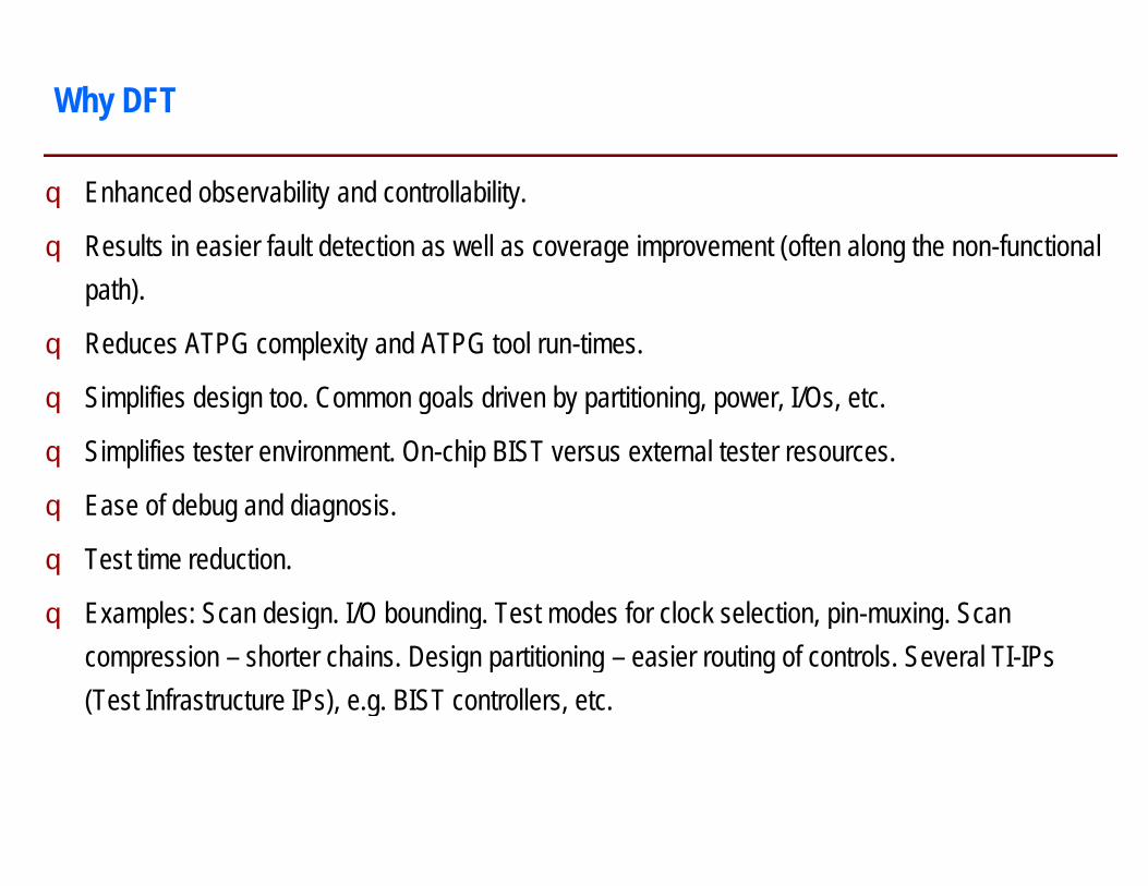
q Enhanced observability and controllability.
q Results in easier fault detection as well as coverage improvement (often along the nonpath).
q Reduces ATPG complexity and ATPG tool run-
q Simplifies design too. Common goals driven by partitioning, power, I/Os, etc.
q Simplifies tester environment. On-chip BIST versus external tester resources.
q Ease of debug and diagnosis.
q Test time reduction.
q Examples: Scan design. I/O bounding. Test modes for clock selection, pincompression – shorter chains. Design partitioning (Test Infrastructure IPs), e.g. BIST controllers, etc.
Why DFT
Results in easier fault detection as well as coverage improvement (often along the non-functional
-times.
Simplifies design too. Common goals driven by partitioning, power, I/Os, etc.
chip BIST versus external tester resources.
Examples: Scan design. I/O bounding. Test modes for clock selection, pin-muxing. Scan shorter chains. Design partitioning – easier routing of controls. Several TI-IPs
(Test Infrastructure IPs), e.g. BIST controllers, etc.

q IP and SOC test and integration:¦ Various test modes and related controls.¦ To enable DFT / enable intra-IP and inter-
IP test.
q Test wrappers:¦ Bounding controls. Inter-IP and intra-IP
controls. ExTest and InTest modes.
q Test interfaces:¦ JTAG, 1500.
q For ATPG:¦ Scan and clock controls.
q For TTR:¦ Higher multi-site. Reduced pin-count test.¦ Self-test.
Examples of DFT
q For low power test:¦ Test of DUT: ATPG fill or scan
partitioning techniques.¦ Test of PM. Test with PM.
q For online test:¦ Memory ECC.¦ Normal mode / test mode concurrency.¦ Self-test. ¦ Logic ECC. What are valid / invalid
opcodes / operands (code-words)?¦ Mapping of CW -> CW / NCW in
absence / presence of faults.
q For reliability / yield:¦ Monitors. Margins.. Calibrators.
Redundancy.

Defects, faults and errors:
q Defects must results in faults. Faults must result in observable errors. Test depends upon observable errors.
q Margins help tolerate (marginal) defects. No resulting faults. Approximate tests can now detect gross defects. Examples: Transition fault ATPG (no delay measurement). Structural tests for analog / RF circuits (no performance measurement).
q Non-maskable faults must be detected or tolerated.
Single fault considered during ATPG. Multiple faults occur in DUT. No coverage lost.
q All MFs detected if all SFs are detected (across all patterns) and if no one fault impacts another.
q A fault must be detected before another one occurs, i.e. two faults must not occur faster than the test application time for all faults.
q Redundant logic can cause failure of irredundant logic.
Defects, Faults and Errors
Defects must results in faults. Faults must result in observable errors. Test depends upon
Margins help tolerate (marginal) defects. No resulting faults. Approximate tests can now detect gross defects. Examples: Transition fault ATPG (no delay measurement). Structural tests for analog / RF circuits (no performance measurement).
faults must be detected or tolerated.
Single fault considered during ATPG. Multiple faults occur in DUT. No coverage lost.
All MFs detected if all SFs are detected (across all patterns) and if no one fault impacts another.
A fault must be detected before another one occurs, i.e. two faults must not occur faster than the
Redundant logic can cause failure of irredundant logic.

Single fault and multiple faults.
Redundant logic affecting non-redundant logic.
Examples
A
B
I1I2I3I4
Z
S1 S2
S1
S2
I1
Coupling
Z A B Z A/1 Multiple faults1 0 0 0 0 -> B/00 1 0 1 0 -> Z/11 1 1 1 1
S1 S2 Z0 0 I10 1 I21 0 I31 1 I4 Unused, But I1 forced to 1

Redundant Logic
q Structurally redundant logic in Consensus theorem not covered with any input.
q Unused logic in 3-1 mux not covered with functional inputs.
q Unoptimised set of minterms require additional non
AS Z = A.S + B.S’ + A.B
OR
X
never tested
AB
BS’
AB 00S 0 0
1 0
Structurally redundant logic in Consensus theorem not covered with any input.
not covered with functional inputs.
require additional non-functional inputs. Practically very relevant.
00 01 11 100 1 1 00 0 1 1

Fault Models and Fault Sizes
# Nets N# Gates G = N# Transistors 5 * G# Paths (N / 10) / 1000Slack paths N * 3
FM Single faults
SAF 2*NTDF 2*NPDF 2*PSDD 2*N*3SBF N*(N-1) / 2 * (4-2)DBF N*(N-1) / 2 * (16-4)TGF / Pseudo SAF / Iddq 2*NFunctional Unbounded
Multiple faults Total
2, 3, …, N at a time2, 3, …, N at a time2, 3, …, N at a time
Unbounded

q Equivalent faults.
q Fault dominance.
q Fault class dominance. SAF w.r.t. others. SAF coverage is effective, though not sufficient.
q Examples.
Fault List Pruning
a bc
d
Equivalent Dominanta b Y Eitherb c N b over cb d N b over dc d N N
. others. SAF coverage is effective, though not sufficient.
Other faults TDF – DominatedSAF - Dominant
DominantEither
b over cb over d
Additional Faults in Memories – Example of what is Different from Logic
Neighbourhoodq Interaction
q For each centre bit, and 16 Distance 2
q Number of distance N [(2*N
q Different topologies drive tile formation and test sequences.
q Exponential complexity of March algorithms for small N.
Successive R/W operations:
q To stress the bitBoth these require non
Conventional CPU code will fail to catch them.
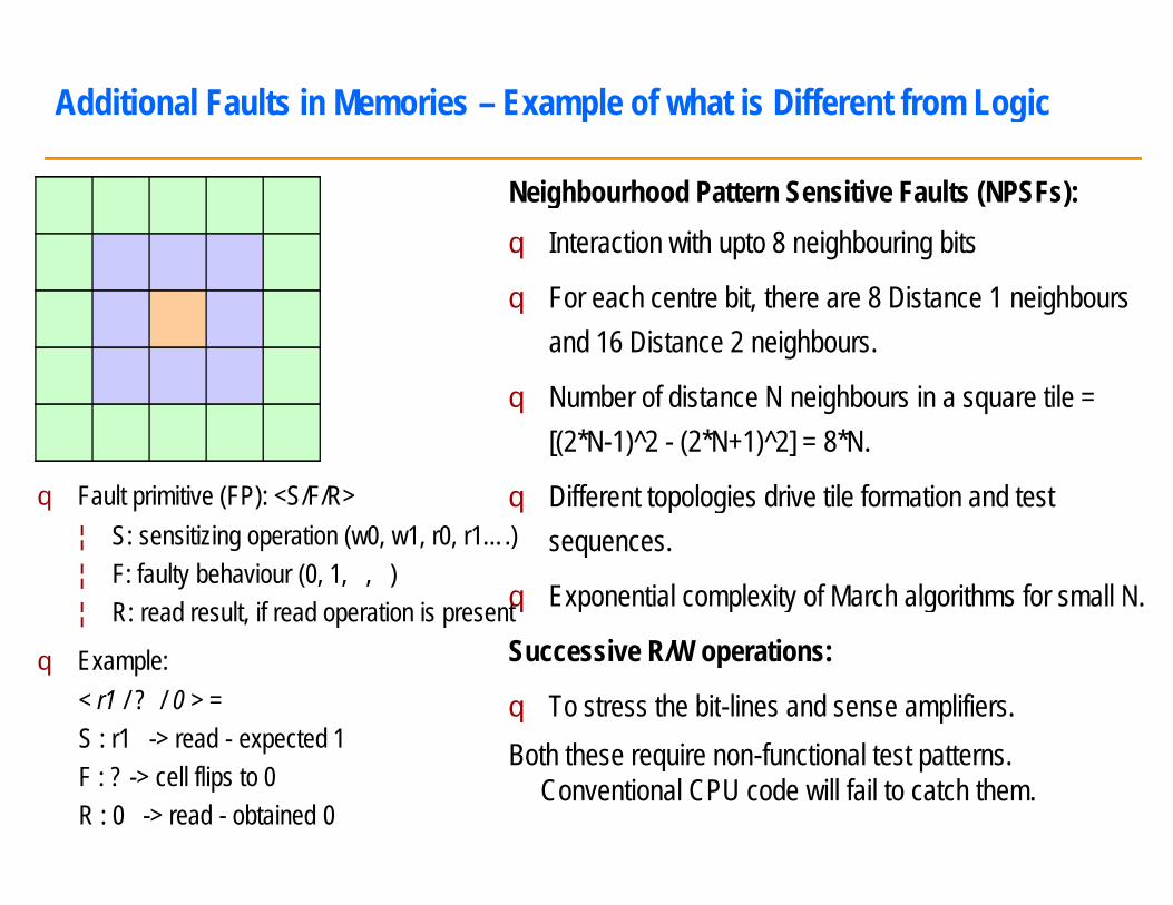
q Fault primitive (FP): <S/F/R>¦ S: sensitizing operation (w0, w1, r0, r1….)¦ F: faulty behaviour (0, 1, , )¦ R: read result, if read operation is present
q Example:< r1 / ? / 0 > =S : r1 -> read - expected 1F : ? -> cell flips to 0R : 0 -> read - obtained 0
Example of what is Different from Logic
Neighbourhood Pattern Sensitive Faults (NPSFs):Interaction with upto 8 neighbouring bits
For each centre bit, there are 8 Distance 1 neighboursand 16 Distance 2 neighbours.
Number of distance N neighbours in a square tile = [(2*N-1)^2 - (2*N+1)^2] = 8*N.
Different topologies drive tile formation and test sequences.
Exponential complexity of March algorithms for small N.
Successive R/W operations:
To stress the bit-lines and sense amplifiers.Both these require non-functional test patterns.
Conventional CPU code will fail to catch them.
Why Stuck-at Fault Model?
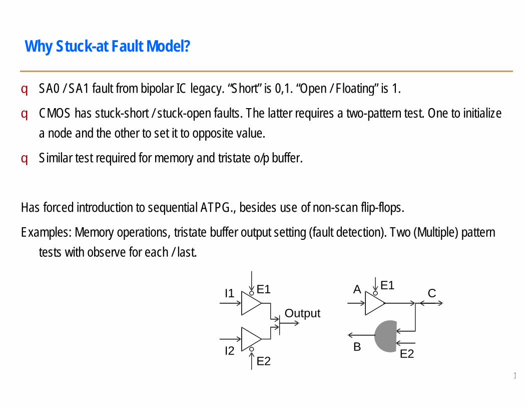
q SA0 / SA1 fault from bipolar IC legacy. “Short” is 0,1. “Open / Floating” is 1
q CMOS has stuck-short / stuck-open faults. The latter requires a twoa node and the other to set it to opposite value.
q Similar test required for memory and tristate o/p buffer
Has forced introduction to sequential ATPG., besides use
Examples: Memory operations, tristate buffer output setting (fault detection). Two (Multiple) pattern tests with observe for each / last.
I1
I2
E1
E2
SA0 / SA1 fault from bipolar IC legacy. “Short” is 0,1. “Open / Floating” is 1.
open faults. The latter requires a two-pattern test. One to initialize o opposite value.
o/p buffer.
forced introduction to sequential ATPG., besides use of non-scan flip-flops.
buffer output setting (fault detection). Two (Multiple) pattern
E1
E2
Output
E1
E2
A
B
C
10

Inputs and States
PIs POs
PresentState
NextState
Combinational
Combinational circuit:q Number of possible input combinations for a
combinational circuit is 2^(#PI).q Number of possible output combinations <= Number of
possible input combinations.q No fixed relationship between functional specification
and test patterns: #PI and #PO. Number of specified combinations out of 2^(#PI) and 2^(#PO).
Sequential circuit:q States complicate this process further.q More possible input combinations: 2^(#PI + #PS).q Each PS may require cycling through many PI+NS
combinations.q Handled by unrolling different sequential frames into
consecutive combinational frames.q NS and PS faults must be observed only on
Combinational circuit:Number of possible input combinations for a combinational circuit is 2^(#PI).Number of possible output combinations <= Number of possible input combinations.No fixed relationship between functional specification and test patterns: #PI and #PO. Number of specified combinations out of 2^(#PI) and 2^(#PO).
Sequential circuit:States complicate this process further.More possible input combinations: 2^(#PI + #PS).Each PS may require cycling through many PI+NS combinations.Handled by unrolling different sequential frames into consecutive combinational frames.NS and PS faults must be observed only on POs. 11
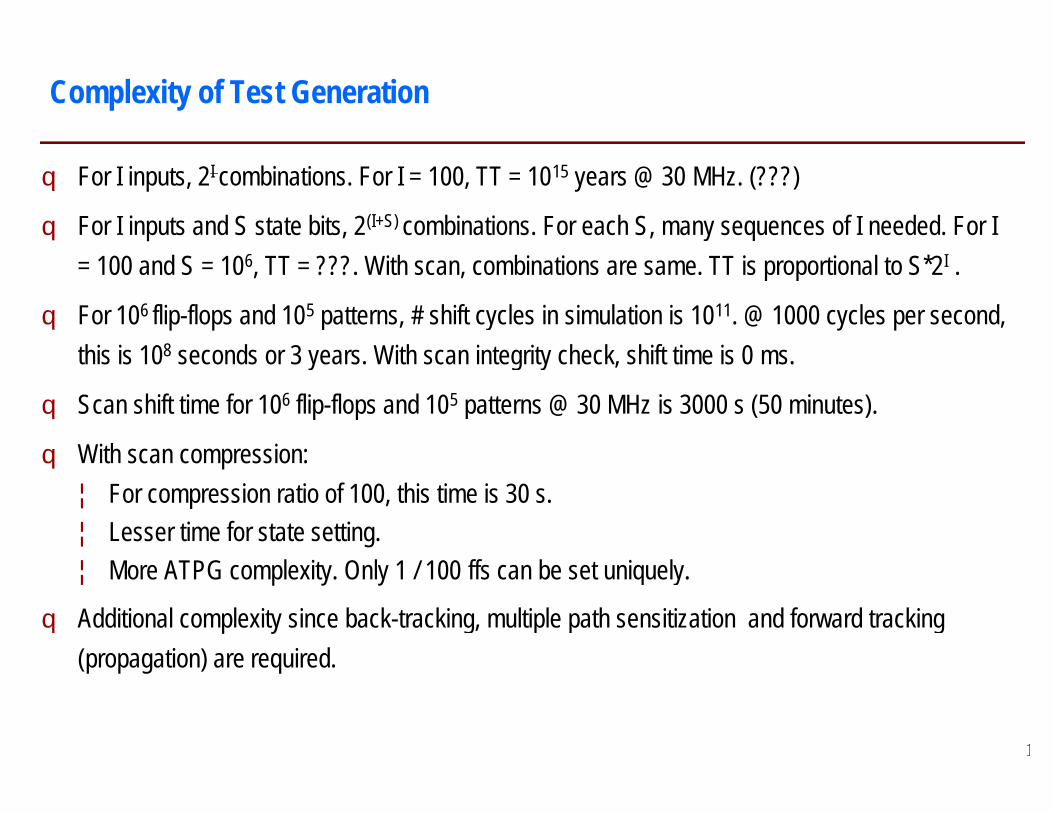
q For I inputs, 2I combinations. For I = 100, TT = 10
q For I inputs and S state bits, 2(I+S) combinations. For each S, many sequences of I needed. For I = 100 and S = 106, TT = ???. With scan, combinations are same. TT is proportional to S*2
q For 106 flip-flops and 105 patterns, # shift cycles in simulation is 10this is 108 seconds or 3 years. With scan integrity check, shift time is 0
q Scan shift time for 106 flip-flops and 105 patterns @ 30 MHz is 3000 s (50 minutes).
q With scan compression:¦ For compression ratio of 100, this time is 30 s.¦ Lesser time for state setting.¦ More ATPG complexity. Only 1 / 100 ffs can be set uniquely.
q Additional complexity since back-tracking, multiple path sensitization and forward tracking (propagation) are required.
Complexity of Test Generation
combinations. For I = 100, TT = 1015 years @ 30 MHz. (???)
combinations. For each S, many sequences of I needed. For I , TT = ???. With scan, combinations are same. TT is proportional to S*2I .
patterns, # shift cycles in simulation is 1011. @ 1000 cycles per second, seconds or 3 years. With scan integrity check, shift time is 0 ms.
patterns @ 30 MHz is 3000 s (50 minutes).
For compression ratio of 100, this time is 30 s.
can be set uniquely.
tracking, multiple path sensitization and forward tracking
12

Schneider’s Circuit
Illustration for:q Forward propagation (D drive) and backward justification.q Multiple path sensitisation.q Non-optimal and optimal pattern sets. Non-unique pattern sets.
Forward propagation (D drive) and backward justification.
unique pattern sets.13

D-algebra:q What is need for multi-valued logic representation for ATPG?q Examples to illustrate “D frontier”. q Simplification provided by PODEM, FAN and other test generation algorithms.q Iterative model of sequential circuit for test generation. D propagation across frames.
Flow for test generation:q Fault simulation: Need and methods.q Fault list management.q Fault classification (detectable / undetectable / tested / untested).q Pattern compaction: Static and dynamic.q Using don’t care bits.
Questions: Optimised logic => Sometimes more patterns? Larger circuits => More don’t care bits? Larger circuits => Lesser entropy?
ATPG Topics
valued logic representation for ATPG?
Simplification provided by PODEM, FAN and other test generation algorithms.Iterative model of sequential circuit for test generation. D propagation across frames.
Fault classification (detectable / undetectable / tested / untested).
logic => Sometimes more patterns? Larger circuits => More don’t care bits? 14
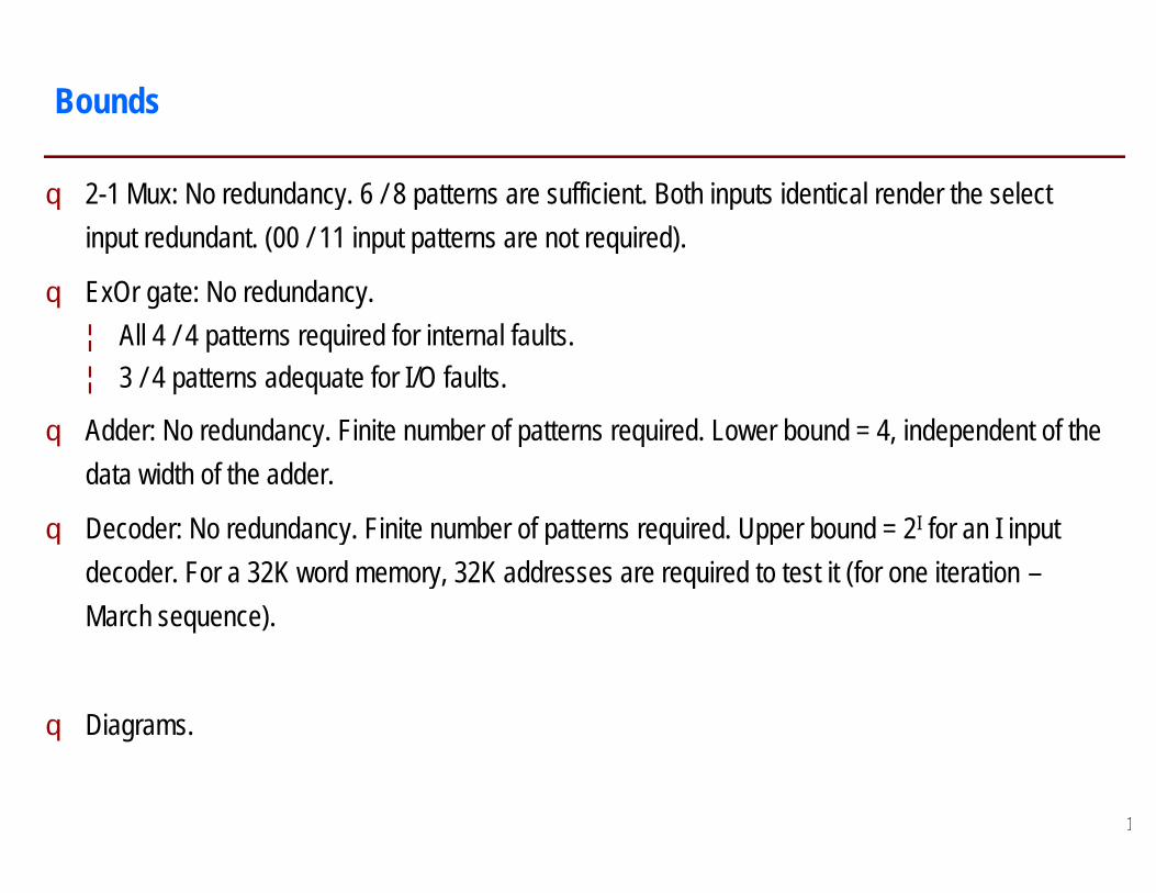
q 2-1 Mux: No redundancy. 6 / 8 patterns are sufficient. Both inputs identical render the select input redundant. (00 / 11 input patterns are not required).
q ExOr gate: No redundancy.¦ All 4 / 4 patterns required for internal faults.¦ 3 / 4 patterns adequate for I/O faults.
q Adder: No redundancy. Finite number of patterns required. Lower bound = 4, independent of the data width of the adder.
q Decoder: No redundancy. Finite number of patterns required. Upper bound = 2decoder. For a 32K word memory, 32K addresses are required to test it (for one iteration March sequence).
q Diagrams.
Bounds
: No redundancy. 6 / 8 patterns are sufficient. Both inputs identical render the select input redundant. (00 / 11 input patterns are not required).
Adder: No redundancy. Finite number of patterns required. Lower bound = 4, independent of the
Decoder: No redundancy. Finite number of patterns required. Upper bound = 2I for an I input decoder. For a 32K word memory, 32K addresses are required to test it (for one iteration –
15
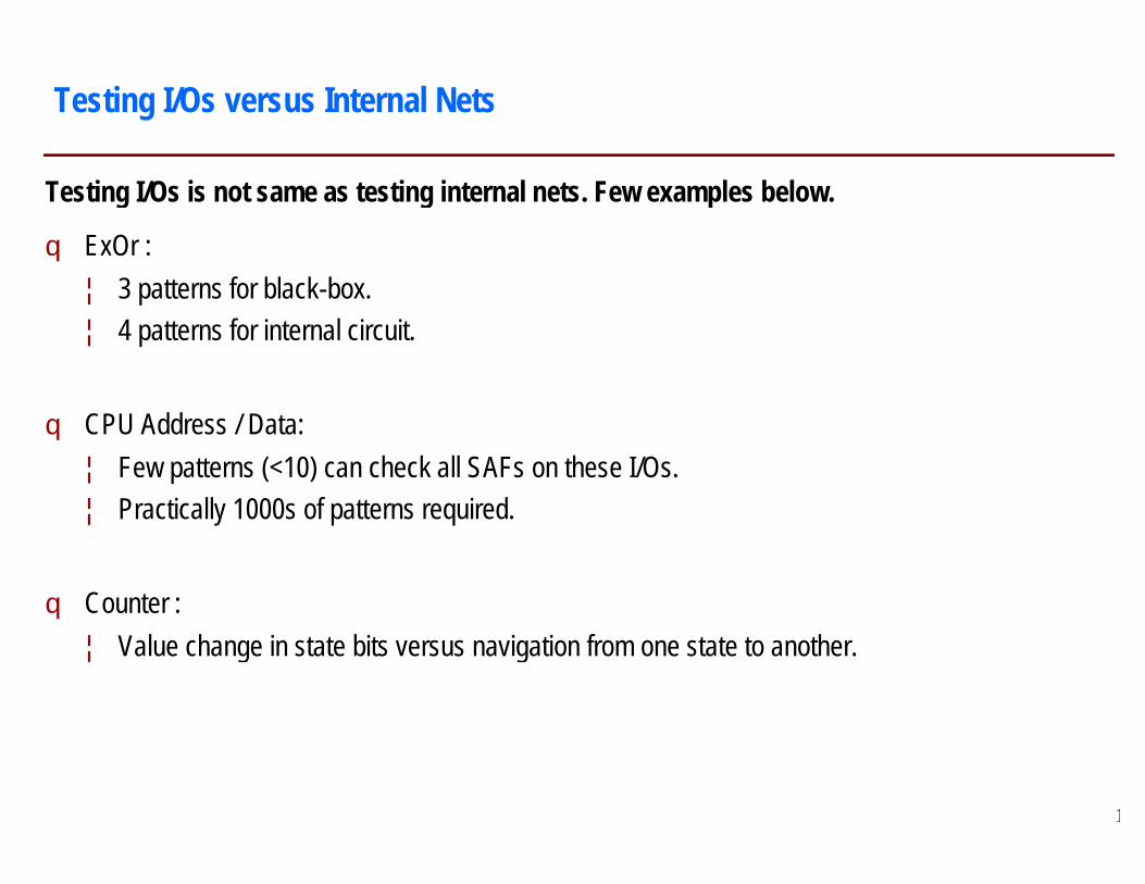
Testing I/Os is not same as testing internal nets. Few examples below.
q ExOr :¦ 3 patterns for black-box.¦ 4 patterns for internal circuit.
q CPU Address / Data:¦ Few patterns (<10) can check all SAFs on these I/Os.¦ Practically 1000s of patterns required.
q Counter :¦ Value change in state bits versus navigation from one state to another.
Testing I/Os versus Internal Nets
Testing I/Os is not same as testing internal nets. Few examples below.
Few patterns (<10) can check all SAFs on these I/Os.
Value change in state bits versus navigation from one state to another.
16

q DFT+ BIST / DUT:¦ Bad / Bad è Bad.¦ Good / Bad è Bad.¦ Bad / Good è Bad.¦ Good / Good è Good.
q Probable defect in DFT + BIST logic is acceptable. Discard the device. Systematic defect is not.
q In comparison, the tester is never faulty.
Test Logic Is Good / Bad
Probable defect in DFT + BIST logic is acceptable. Discard the device. Systematic defect is not.
17

Scan Implementation
Exclusive Scan pathFunctional path
SI1
SO1
SE
From other FF(Q)
From other FF(Q)
To other FF(D)
Cycles 1 2 3SI1SI2SESO1SO2
DSD
QFF1
FF2
FF3
Exclusive Scan pathFunctional path
SI2
SO2
From other FF(Q)
From other FF(Q)
To other FF(D)
4 5 6 7
18
FF5
FF4
FF6

q SE can be shared between two scan chains if they are running in tandem, they are running independently.
q Shift-out for Pattern P1 happens in parallel with shift
q Cycles1,2,3,5,6,7: ¦ SI1->FF1(SD)->FF1(Q)->FF2(SD)->FF2(Q)¦ SI2->FF4(SD)->FF4(Q)->FF5(SD)->FF5(Q)
q End of Cycle 3: End of shift-in. Pattern from FFs(Q) applied to logic.
q End of Cycle 4: Response captured into FFs(D). Start of shift
Scan Implementation (2)
chains if they are running in tandem, or can be dedicated if
out for Pattern P1 happens in parallel with shift-in for Pattern P2.
>FF2(Q)->FF3(SD)->FF3(Q)->SO1.>FF5(Q)->FF6(SD)->FF6(Q)->SO2.
in. Pattern from FFs(Q) applied to logic.
4: Response captured into FFs(D). Start of shift-out.
19

Design aspects:
q Types of scan flip-flops.
q Inputs / Outputs and controls required.
q Number of scan chains and lengths.
q Order of stitching flip-flops into scan chains.
q Stitching across IPs / Domains.
q Full scan versus partial scan.
Scan: Changes state setting complexity from exponential to linear.
q Ease of controllability. Ease of observability.
q No need for scan shift simulations after scan integrity checks.
q At-speed next state generation possible without tester inputs.
Various Aspects of Scan
Scan: Changes state setting complexity from exponential to linear.
No need for scan shift simulations after scan integrity checks.
speed next state generation possible without tester inputs.20

Scan Compression
DECOMPRESSOR
SPREADING NETWORK
SPACE COMPACTOR
SEQUENTIAL COMPACTOR
From Tester
To Tester
DUT
CoDec
CoDec
• Several don’t care bits in every scan pattern.• More of them for the latter patterns.
è Scope for compression.
Two aspects:• Few external channel (from tester) connected
to many internal scan chains.• Long chains converted to shorter chains.
21
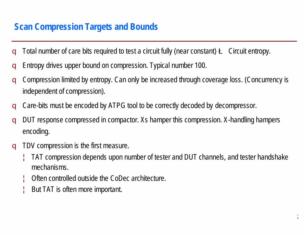
q Total number of care bits required to test a circuit fully (near constant)
q Entropy drives upper bound on compression. Typical number 100.
q Compression limited by entropy. Can only be increased through coverage loss. (Concurrency is independent of compression).
q Care-bits must be encoded by ATPG tool to be correctly decoded by
q DUT response compressed in compactor. Xs hamper this compression. Xencoding.
q TDV compression is the first measure.¦ TAT compression depends upon number of tester and DUT channels, and tester handshake
mechanisms. ¦ Often controlled outside the CoDec architecture.¦ But TAT is often more important.
Scan Compression Targets and Bounds
Total number of care bits required to test a circuit fully (near constant) è Circuit entropy.
Entropy drives upper bound on compression. Typical number 100.
Compression limited by entropy. Can only be increased through coverage loss. (Concurrency is
bits must be encoded by ATPG tool to be correctly decoded by decompressor.
DUT response compressed in compactor. Xs hamper this compression. X-handling hampers
TAT compression depends upon number of tester and DUT channels, and tester handshake
architecture.
Scan Compression Targets and Bounds
22

q Ubiquitous need for non-functional inputs:¦ Examples: Memory back-to-back reads / writes,
gate, structural redundancy in synthesised logic (nonredundancy in 3-1 mux, counter with unused states, etc.
¦ Iddq: Non-functional inputs are also required for transistor defects, e.g. 00 input to twoNAND gate.
q Scan state itself is not functional:¦ Next state after scan shift is not necessarily functional. It is just reachable.¦ Launch-off capture and launch-off shift patterns can both have non¦ Path delay pattern: Just a valid transition, not necessarily a valid path.
q Memory RAM sequential patterns have several scan operations per pattern (five below):¦ Scan Address2 => Write Data2 (initialize).¦ Scan Address1 => Write Data1.¦ Scan Address2 => Read Data2. (Detects faults where A1 maps incorrectly to A2).
Functional and Structural Tests
back reads / writes, tristate two pattern sequential test, EXOR logic (non-minimal set of minterms), functional
, counter with unused states, etc. functional inputs are also required for transistor defects, e.g. 00 input to two-input
Next state after scan shift is not necessarily functional. It is just reachable.off shift patterns can both have non-functional launch states.
Path delay pattern: Just a valid transition, not necessarily a valid path.
Memory RAM sequential patterns have several scan operations per pattern (five below):
Scan Address2 => Read Data2. (Detects faults where A1 maps incorrectly to A2).23
Iddq Current Test
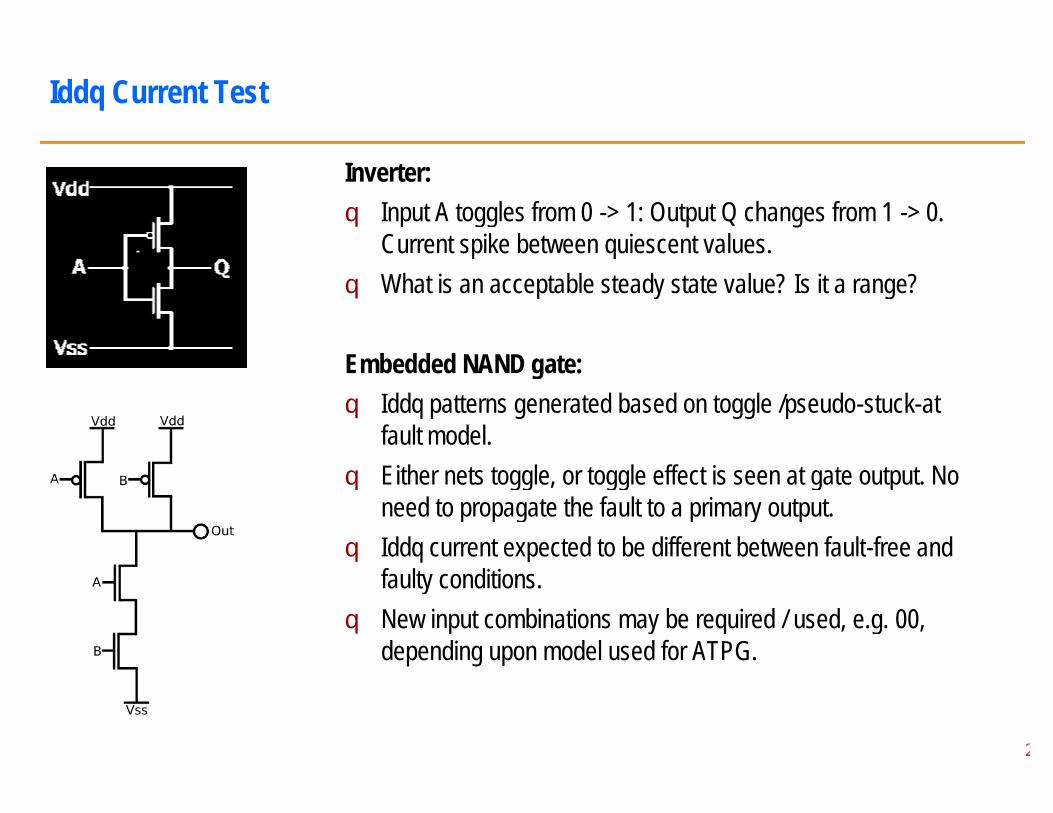
Inverter:q Input A toggles from 0
Current spike between quiescent values.q What is an acceptable steady state value? Is it a range?
Embedded NAND gate:q Iddq patterns generated based on toggle /pseudo
fault model.q Either nets toggle, or toggle effect is seen at gate output. No
need to propagate the fault to a primary output.q Iddq current expected to be different between fault
faulty conditions.q New input combinations may be required / used, e.g.
depending upon model used for ATPG.
Input A toggles from 0 -> 1: Output Q changes from 1 -> 0. Current spike between quiescent values.
is an acceptable steady state value? Is it a range?
Embedded NAND gate:patterns generated based on toggle /pseudo-stuck-at
Either nets toggle, or toggle effect is seen at gate output. No need to propagate the fault to a primary output.
current expected to be different between fault-free and faulty conditions.New input combinations may be required / used, e.g. 00,
upon model used for ATPG.
24

Iddq Threshold
Four quadrants:q Device vs Iddq:
¦ Good / Low.¦ Good / High.¦ Bad / Low.¦ Bad / High.
q Yield recovery in the middle two cases through setting appropriate thresholds and outlier analysis.
25

Waveforms for Different Patterns
shift_in shift_outcapture
shift_in shift_outMultiple captures
Iddq, TGF pattern.
shift_in shift_outno capture
Combinational ATPG / SAF pattern.
Sequential ATPG / TRF pattern.
26
Example
Cycles Shift1 Shift2 Shift3/InitFF1(Q)FF2(Q)FF4(D)
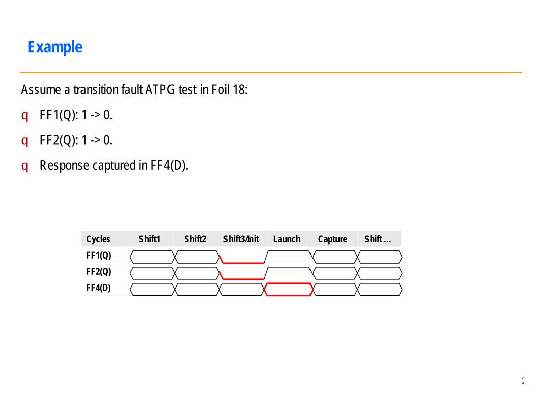
Assume a transition fault ATPG test in Foil 18:
q FF1(Q): 1 -> 0.
q FF2(Q): 1 -> 0.
q Response captured in FF4(D).
2727
Launch Capture Shift …

Two pattern tests: V1 -> V2. V1 is initialisation pattern. V2 is launch pattern.
q Launch condition enabled through scan initialisation
q Next state after scan shift is not necessarily functional. Depends on synthesis of next state functional. Very likely only reachable for incompletely state machines.
q Reachable ? Functional. Former depends upon synthesis. Latter depends upon specification. For a completely specified machine, the two are same.
q Launch-off capture and launch-off shift patterns can both have non
At-speed ATPG Tests
pattern. V2 is launch pattern.
initialisation (non-functional).
Next state after scan shift is not necessarily functional. Depends on synthesis of next state functional. Very likely only reachable for incompletely state machines.
Reachable ? Functional. Former depends upon synthesis. Latter depends upon specification. For a completely specified machine, the two are same.
off shift patterns can both have non-functional launch states.
28

q Three methods for launch (V2), after initialization (V1):¦ V2 is shifted value of V1 (combinational). Different V2 for all V1 guaranteed.¦ V2 is functional state of V1 (sequential). Different V2 for all V1 not guaranteed.¦ V2 is functional state of V1 after many cycles. Higher chance of V2 being different from V1.¦ V2 and V1 are independent (two sets of scan flip
Two Pattern Tests
shift_in (LOS)launch
Launch off shift
Launch off capturescan_enable
scan_enable
V1 V2
Orig. SCEnhanced SC
shift_in (LOC)
Three methods for launch (V2), after initialization (V1):V2 is shifted value of V1 (combinational). Different V2 for all V1 guaranteed.V2 is functional state of V1 (sequential). Different V2 for all V1 not guaranteed.V2 is functional state of V1 after many cycles. Higher chance of V2 being different from V1.V2 and V1 are independent (two sets of scan flip-flops – enhanced scan chain).
shift_outlaunch
capture
V1 V2
Enhanced SC29

q Transition fault pattern does not necessarily cause a transition in the capture flip¦ 0->1 transition on S is a valid transition fault test for A = 1 and B =1¦ Fault-free output does not change: 1->1. Faulty o/p: 1
q Path delay pattern: A transition in capture flip-flop is guaranteed. However, not necessarily through a valid path.
q Path delay tests can be robust (single launch transition), nontransitions), functional sensitisable (other enabling paths). Considerations for multiand false paths.
q Multiple cycle launches may be required to achieve a functional launch state.
Desirable Transitions
AS Z = A.S + B.S’
BS’
Transition fault pattern does not necessarily cause a transition in the capture flip-flop.>1 transition on S is a valid transition fault test for A = 1 and B =1->0.
>1. Faulty o/p: 1 -> 0.
flop is guaranteed. However, not necessarily
Path delay tests can be robust (single launch transition), non-robust (other enabling launch (other enabling paths). Considerations for multi-cycle paths
Multiple cycle launches may be required to achieve a functional launch state.
30

Small Delay Defects
Earlier metric:
• # transition faults detected.
New metric:
• # transition faults detected weighted as:
• (Fault * Minimal slack) / (Slack along detected path)
• Area under the slack curve.
q Take all patterns for a given slack – accept coverage obtained.
q Take all patterns for a given coverage – accept slack used. % of detection path slack w.r.t.
minimum path slack
Pattern count
10% 20% 30% 40% 50% 60%
31
0
5
10
4 8 12 16 20 24 28 32 36 40 44
Slack
Nod
es
% of detection path slack w.r.t. minimum path slack
Coverage
10% 20% 30% 40% 50% 60% 10% 20% 30% 40% 50% 60%% of detection path slack w.r.t.
minimum path slack 31

Defect Oriented Testing
Parameters:q (x,y) co-ordinates.q Radius and area.q Probabilistic distribution considered for number of defects.
Inductive fault analysis: Artwork of faults.
32
Probabilistic distribution considered for number of defects.32

A. Assume SA0 and SA1 faults on all nets:1. Generate an optimal pattern set for Schneider’s circuit on Foil 13.2. Generate an optimal pattern set for the tristate3. Generate an optimal pattern set for a full adder circuit with two inputs of two bits each.4. Generate an optimal pattern set for a three bit binary counter using D flip
outputs (with reset state of all 0s). For the same circuit, generate an optimal pattern set with only an over-flow output, which is set when the state flip
B. Assume S-R and S-F faults on all nets:1. Generate an optimal pattern set for the tristate2. Generate an optimal pattern set for the three bit binary counter in A(4) for both the cases.3. Consider the case where this binary counter iis
generated for state 101.
Assignments
Generate an optimal pattern set for Schneider’s circuit on Foil 13.tristate buffer circuits on Foil 10.
Generate an optimal pattern set for a full adder circuit with two inputs of two bits each.Generate an optimal pattern set for a three bit binary counter using D flip-flops with states as outputs (with reset state of all 0s). For the same circuit, generate an optimal pattern set with
flow output, which is set when the state flip-flops are all1s.
tristate buffer circuits on Foil 10.Generate an optimal pattern set for the three bit binary counter in A(4) for both the cases.
iis used only for five states, i.e. overflow is
33

Backup
34