Fault Detection, Isolation and Fault-Tolerant Control of ...
67
Fault Detection, Isolation and Fault-Tolerant Control of Wind Turbines A Takagi-Sugeno and Sliding Mode Approach Prof. Dr.-Ing. Horst Schulte University of Applied Sciences Berlin School of Engineering I: Energy and Information Science Chair of Control Engineering Lecture at the Shahrood University of Technology, Department of Mechanics, 1 st October 2019, Shahrood, Iran
Transcript of Fault Detection, Isolation and Fault-Tolerant Control of ...

Fault Detection, Isolation and Fault-Tolerant Control of
Wind Turbines
A Takagi-Sugeno and Sliding Mode Approach
Prof. Dr.-Ing. Horst Schulte
University of Applied Sciences Berlin
School of Engineering I: Energy and Information Science
Chair of Control Engineering
Lecture at the Shahrood University of Technology, Department of Mechanics,
1st October 2019, Shahrood, Iran

- 2 -
Overview
1. Motivation and Problem Formulation
2. Fault Tolerant Control (FTC) Architecture for Wind
Turbine and Sustainable Power Systems
3. Review of Takagi-Sugeno and Sliding Mode
Approaches
4. Fault Detection, Isolation and FTC on Component
Level, Power plant level and Network Level
5. Conclusion
- 3 -
1. Motivation and Problem Formulation
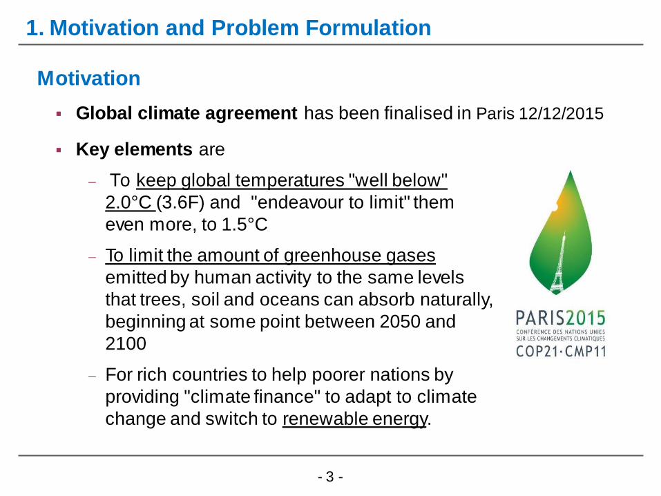
Global climate agreement has been finalised in Paris 12/12/2015
Motivation
Key elements are
To keep global temperatures "well below"
2.0°C (3.6F) and "endeavour to limit" them
even more, to 1.5°C
To limit the amount of greenhouse gases
emitted by human activity to the same levels
that trees, soil and oceans can absorb naturally,
beginning at some point between 2050 and
2100
For rich countries to help poorer nations by
providing "climate finance" to adapt to climate
change and switch to renewable energy.
- 4 -
1. Motivation and Problem Formulation
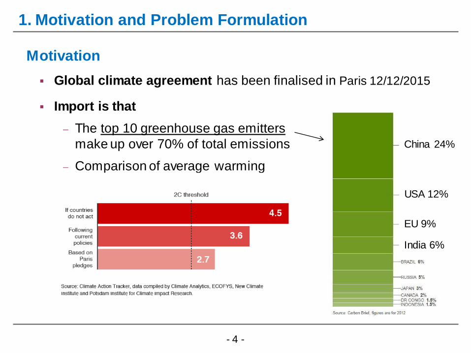
Global climate agreement has been finalised in Paris 12/12/2015
Motivation
Import is that
The top 10 greenhouse gas emitters
make up over 70% of total emissions
Comparison of average warming
China 24%
USA 12%
EU 9%
India 6%

- 5 -
1. Motivation and Problem Formulation
But the agreement must be stepped up if it is to have any
chance of curbing dangerous climate change
That means i.e. a rapid expansion and total switch to
renewable energy
Motivation

- 6 -
1. Motivation and Problem Formulation
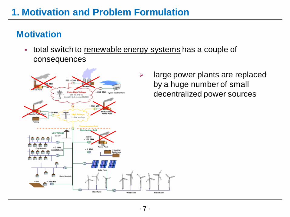
total switch to renewable energy systems has a couple of
consequences
Motivation
- 7 -
1. Motivation and Problem Formulation
total switch to renewable energy systems has a couple of
consequences
Motivation
large power plants are replaced
by a huge number of small
decentralized power sources
- 8 -
1. Motivation and Problem Formulation
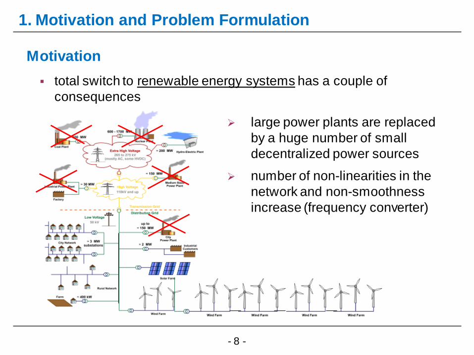
total switch to renewable energy systems has a couple of
consequences
Motivation
large power plants are replaced
by a huge number of small
decentralized power sources
number of non-linearities in the
network and non-smoothness
increase (frequency converter)

- 9 -
1. Motivation and Problem Formulation
total switch to renewable energy systems has a couple of
consequences
Motivation
large power plants are replaced
by a huge number of small
decentralized power sources
number of non-linearities in the
network and non-smoothness
increase (frequency converter)
decentralized power sources are
feeded by fluctuating renewable
energy
- 10 -
1. Motivation and Problem Formulation
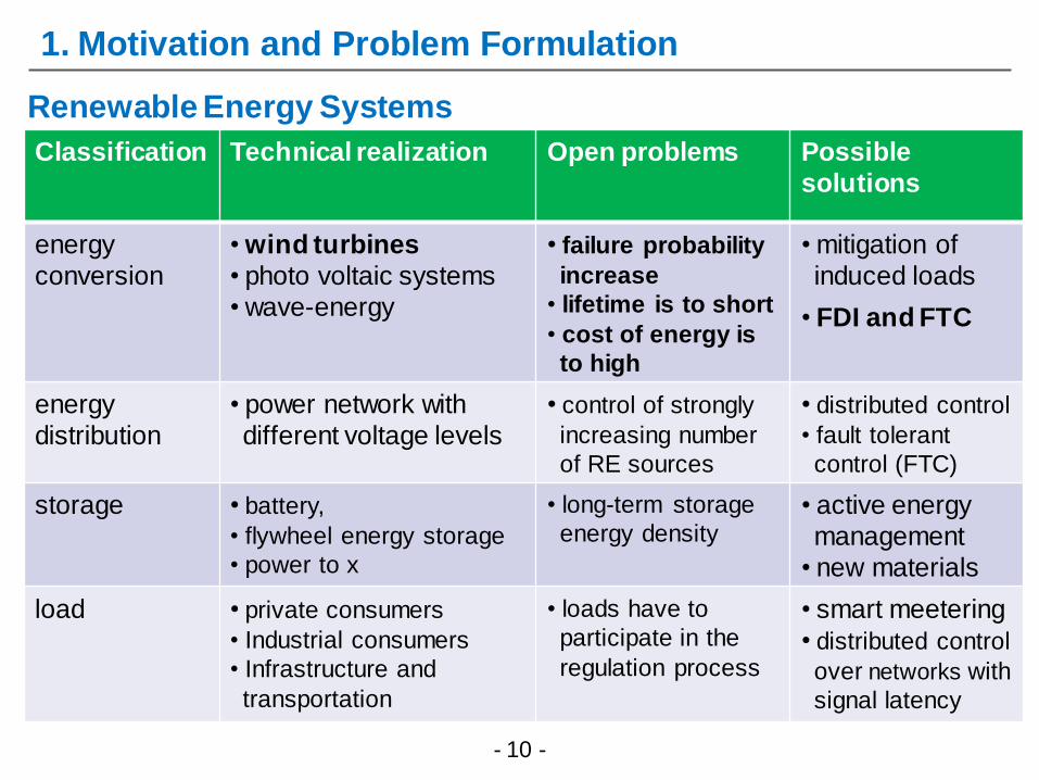
Renewable Energy Systems
Classification Technical realization Open problems Possible
solutions
energy
conversion
• wind turbines
• photo voltaic systems
• wave-energy
• failure probability
increase
• lifetime is to short
• cost of energy is
to high
• mitigation of
induced loads
• FDI and FTC
energy
distribution
• power network with
different voltage levels
• control of strongly
increasing number
of RE sources
• distributed control
• fault tolerant
control (FTC)
storage • battery,
• flywheel energy storage
• power to x
• long-term storage
energy density • active energy
management
• new materials
load • private consumers
• Industrial consumers
• Infrastructure and
transportation
• loads have to
participate in the
regulation process
• smart meetering
• distributed control
over networks with
signal latency
- 11 -
1. Motivation and Problem Formulation
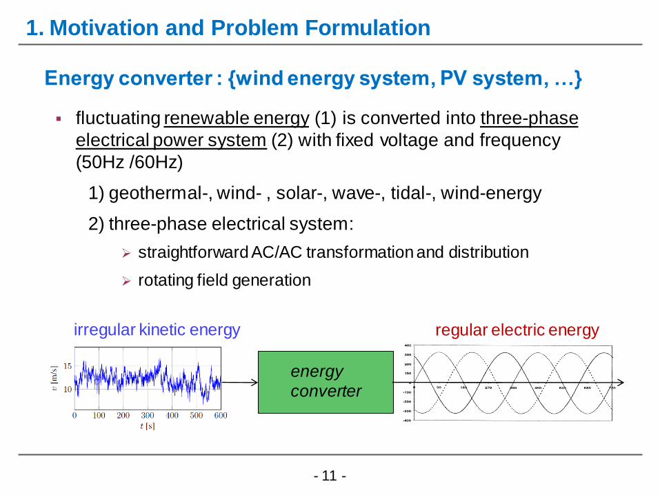
fluctuating renewable energy (1) is converted into three-phase
electrical power system (2) with fixed voltage and frequency
(50Hz /60Hz)
1) geothermal-, wind- , solar-, wave-, tidal-, wind-energy
2) three-phase electrical system:
straightforward AC/AC transformation and distribution
rotating field generation
Energy converter : {wind energy system, PV system, …}
irregular kinetic energy regular electric energy
energy
converter

- 12 -
1. Motivation and Problem Formulation
Energy conversion by means of Wind energy systems
AC/DC DC/DC DC/AC AC/AC
pitch control system control
Excitation
w inding
Boost
converter
netw ork

- 13 -
1. Motivation and Problem Formulation
WAMC: wide area monitoring and control
Electrical Power network

- 14 -
1. Motivation and Problem Formulation
Electrical Power network
WAMC: wide area monitoring and control
AVR: automatic voltage regulation; PSS: power system stabilizer
- 15 -
1. Motivation and Problem Formulation
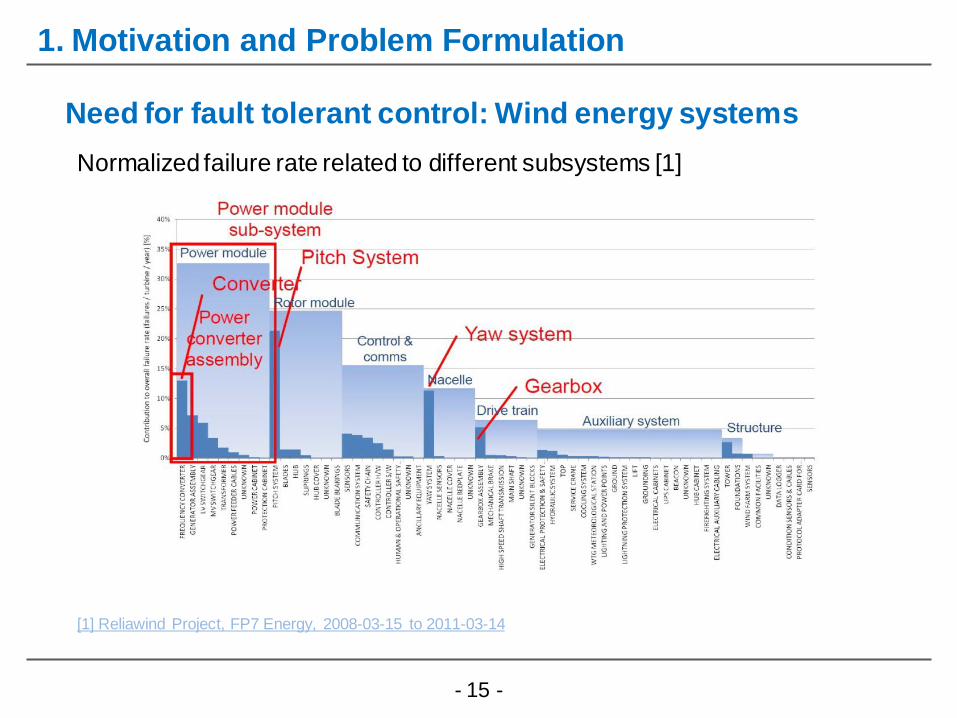
Need for fault tolerant control: Wind energy systems
Normalized failure rate related to different subsystems [1]
[1] Reliawind Project, FP7 Energy, 2008-03-15 to 2011-03-14

- 16 -
1. Motivation and Problem Formulation
Electric power networks (EPN) are the backbone of contemporary
technical civilization
EPN is a vast structure embracing a huge number of generators in
conventional and icreasing number of regenerative power plants
- hundreds of thousand kilometers of lines
- thousand of transformators and power electronic devices
connected in the grid
From the very beginning electric power systems had to be protected
against faults and other abnormal phenomena (embedded fault
tolerance)
Example of earlier electro-mechanical protection
- overcurrent
- undervoltage relays actuated by r.m.s or mean values of rectified signals
Need for fault tolerant control: Electrical power network

- 17 -
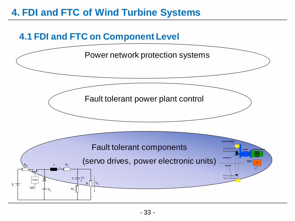
FTC Layers for Complex Regenerative Systems
2. Fault Tolerant Control Architecture
Fault tolerant components
(servo drives, power electronic units)
Fault tolerant power plant control
RM
E
iRL
PWM
u(t)V
C
L
R
V
RC
V0
Power network protection systems

- 18 -
1.) Robustness due to uncertainty in power system dynamics
loads and renewable generation can never be known precisely
To ensure robust performance, controller design must take into account plausible parameter ranges and system conditions
challenge due to the nonlinear, nonsmooth, large-scale nature of power systems
FTC methods: Requirements
2. Fault Tolerant Control Architecture
- 19 -
FTC methods: Requirements
2. Fault Tolerant Control Architecture
2.) Systematic Design Process: from linear to nonlinear design
Scalability
Consideration of various faults
3.) Computability: Synthesis of FTC via computable algorithms
LMI formulation
Riccati Equations
- 20 -
FTC methods: Review
2. Fault Tolerant Control Architecture
there are several approaches to fault tolerant control (FTC),
i.e. [Patton,1997] , [Zhang and Jiang, 2003], [Blanke et al., 2006],
[Noura, Theilliol et. Al, 2009]
FTC can be broadly categorised into passive (PFTC) and active
approaches (AFTC)
AFTC methods, one can distinguish between fault accomodation
and control reconfiguration
Fault accomodation means the adaptation of the controller
parameters to the faulty plant
Control reconfiguration may involve the use of a different control structure altogether, like different inputs and outputs.
- 21 -
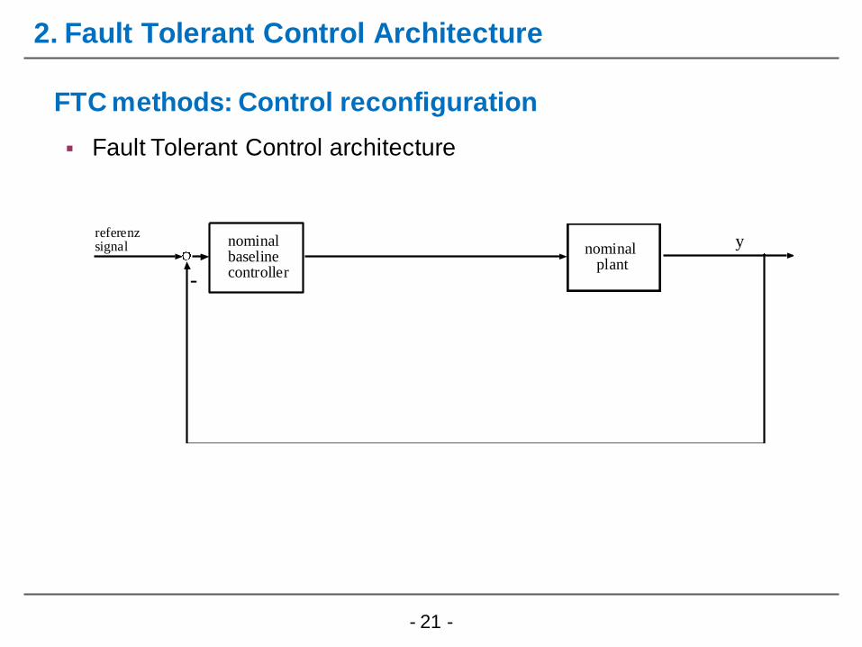
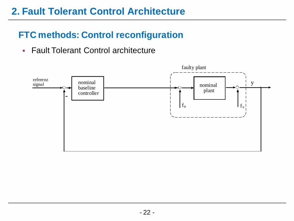
Fault Tolerant Control architecture
FTC methods: Control reconfiguration
2. Fault Tolerant Control Architecture
yreferenzsignal nominal
baselinecontroller-
nominal plant
- 22 -
Fault Tolerant Control architecture
2. Fault Tolerant Control Architecture
yreferenzsignal nominal
baselinecontroller-
nominal plant
sfaf
faulty plant
FTC methods: Control reconfiguration
- 23 -
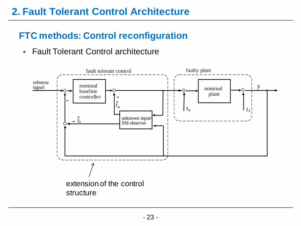
Fault Tolerant Control architecture
2. Fault Tolerant Control Architecture
FTC methods: Control reconfiguration
a f
s
y r e f e r e n z s i g n a l
n o m i n a l b a s e l i n e c o n t r o l l e r
-
n o m i n a l p l a n t
f
f a u l t t o l e r a n t c o n t r o l
u n k n o w n i n p u t / S M o b s e r v e r
s f a f
f a u l t y p l a n t
-
-
extension of the control
structure
- 24 -
3. Review of Takagi-Sugeno and Sliding Mode Approach
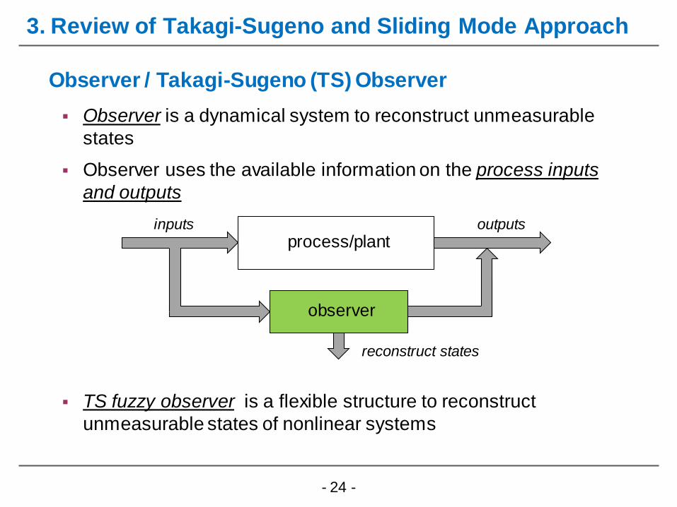
Observer is a dynamical system to reconstruct unmeasurable
states
Observer uses the available information on the process inputs
and outputs
Observer / Takagi-Sugeno (TS) Observer
TS fuzzy observer is a flexible structure to reconstruct
unmeasurable states of nonlinear systems
process/plant
observer
inputs outputs
reconstruct states

- 25 -
Condtion 1: nonlinear plant/process have to formulated as a TS fuzzy system
Condition 2: the vector of premise variables may comprise states, inputs, and
external variables
Condition 3: membership functions fulfill the conditions
TS Fuzzy Observer
3. Review of Takagi-Sugeno and Sliding Mode Approach

- 26 -
Nonlinear switching term establishes and maintains a motion on a
so-called sliding surface => robustness
Takagi-Sugeno Sliding Mode Observer (Gerland/Schulte et al. 2010)
Characteristics
- necessary condition: p > q where p=dim(u)
- robustness with simultaneous disturbances, uncertainties and fault
Sliding Mode Techniques (Utkin 1977, Edwards 2010 for LPV Systems)
TS Luenberg term
switching
term
3. Review of Takagi-Sugeno and Sliding Mode Approach

- 27 -
Takagi-Sugeno Sliding Mode Observer with unmeasurable z
vector of premise variables includes unmeasurable states
unmeasurable states are reconstructed by the observer himself
distinguish between:
Sliding Mode Techniques (Gerland/Schulte et al. 2010, Schulte 2015)
3. Review of Takagi-Sugeno and Sliding Mode Approach
- 28 -
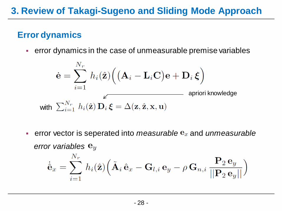
error dynamics in the case of unmeasurable premise variables
with
error vector is seperated into measurable and unmeasurable
error variables
Error dynamics
apriori knowledge
3. Review of Takagi-Sugeno and Sliding Mode Approach
- 29 -
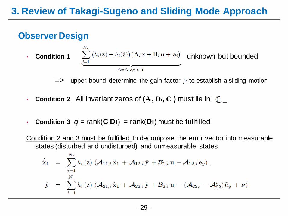
Condition 1 unknown but bounded
=> upper bound determine the gain factor to establish a sliding motion
Condition 2 All invariant zeros of (Ai, Di, C ) must lie in
Condition 3 q = rank(C Di) = rank(Di) must be fullfilled
Condition 2 and 3 must be fullfilled to decompose the error vector into measurable
states (disturbed and undisturbed) and unmeasurable states
Observer Design
3. Review of Takagi-Sugeno and Sliding Mode Approach
- 30 -
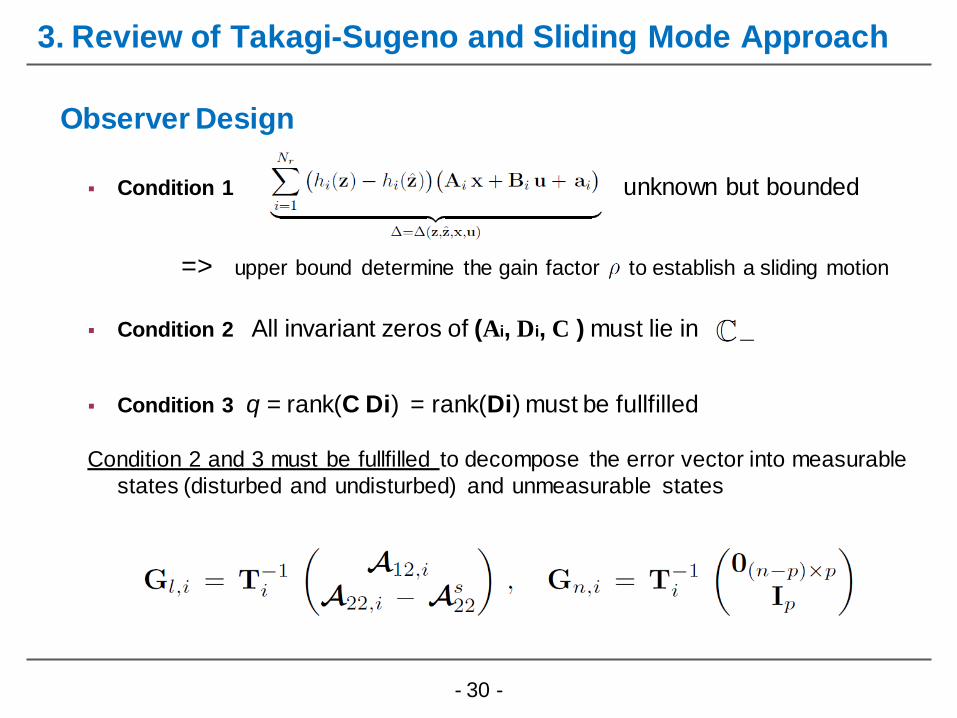
Condition 1 unknown but bounded
=> upper bound determine the gain factor to establish a sliding motion
Condition 2 All invariant zeros of (Ai, Di, C ) must lie in
Condition 3 q = rank(C Di) = rank(Di) must be fullfilled
Condition 2 and 3 must be fullfilled to decompose the error vector into measurable
states (disturbed and undisturbed) and unmeasurable states
Observer Design
3. Review of Takagi-Sugeno and Sliding Mode Approach
- 31 -
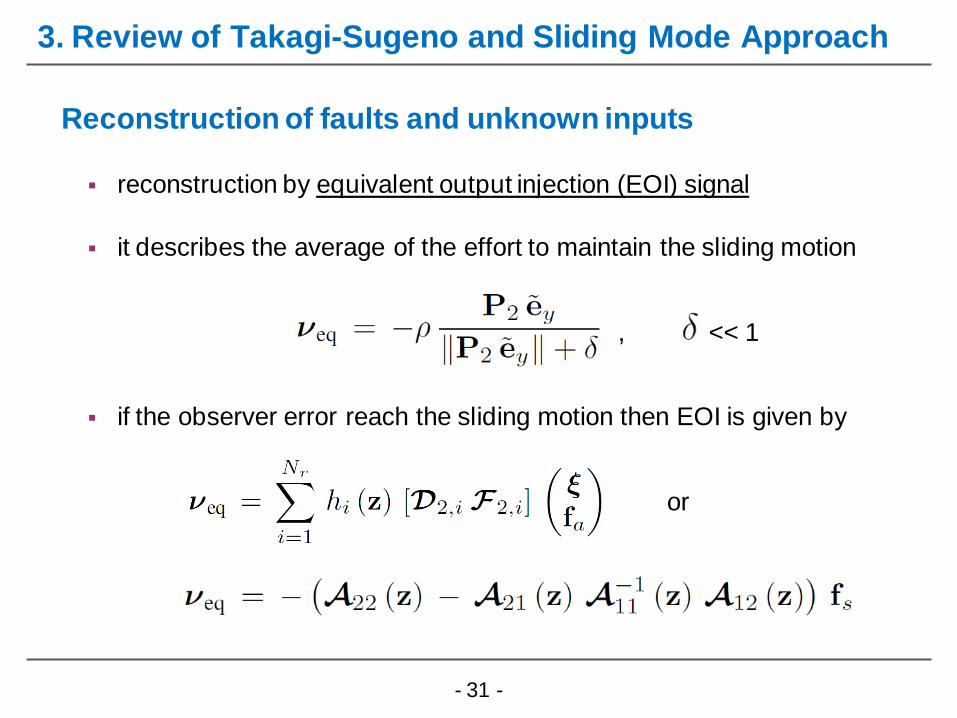
reconstruction by equivalent output injection (EOI) signal
it describes the average of the effort to maintain the sliding motion
, << 1
if the observer error reach the sliding motion then EOI is given by
or
Reconstruction of faults and unknown inputs
3. Review of Takagi-Sugeno and Sliding Mode Approach
- 32 -
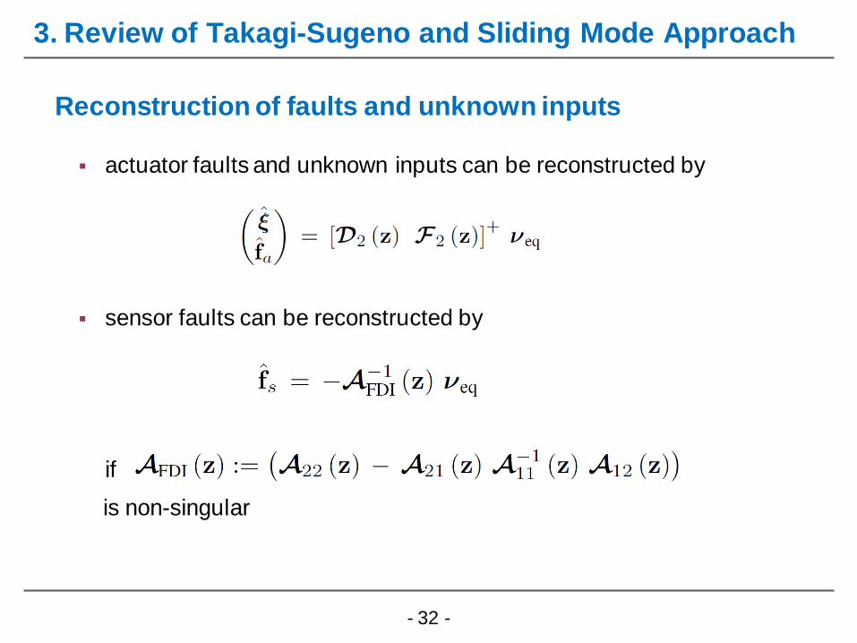
actuator faults and unknown inputs can be reconstructed by
sensor faults can be reconstructed by
if
is non-singular
Reconstruction of faults and unknown inputs
3. Review of Takagi-Sugeno and Sliding Mode Approach
- 33 -
Fault tolerant components
(servo drives, power electronic units)
Fault tolerant power plant control
RM
E
iRL
PWM
u(t)V
C
L
R
V
RC
V0
Power network protection systems
4. FDI and FTC of Wind Turbine Systems
4.1 FDI and FTC on Component Level
- 34 -
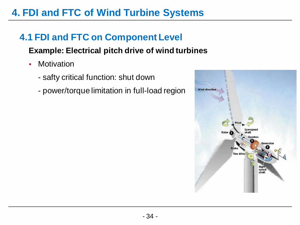
4. FDI and FTC of Wind Turbine Systems
Example: Electrical pitch drive of wind turbines
Motivation
- safty critical function: shut down
- power/torque limitation in full-load region
4.1 FDI and FTC on Component Level

- 35 -
4. FDI and FTC of Wind Turbine Systems
Example: Electrical pitch drive of wind turbines
Motivation
- safty critical function: shut down
- power/torque limitation in full-load region
- reduction due to increasing pitch angle
4.1 FDI and FTC on Component Level

- 36 -
4. FDI and FTC of Wind Turbine Systems
Example: Electrical pitch drive of wind turbines
Objectives
- FDI/FTC of current sensor faults component level
- FDI/FTC pitch angle sensor fault component or system level
4.1 FDI and FTC on Component Level
- 37 -
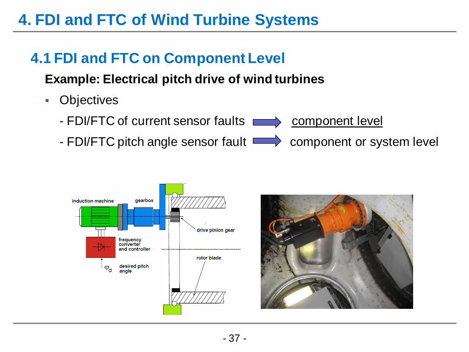
4. FDI and FTC of Wind Turbine Systems
Example: Electrical pitch drive of wind turbines
Objectives
- FDI/FTC of current sensor faults component level
- FDI/FTC pitch angle sensor fault component or system level
4.1 FDI and FTC on Component Level
- 38 -
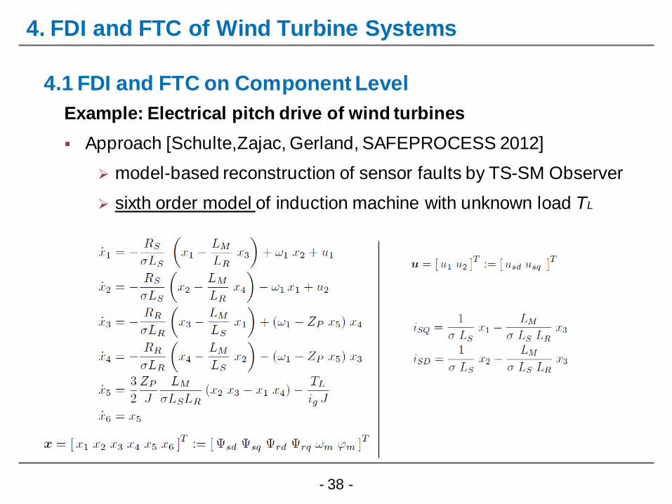
4. FDI and FTC of Wind Turbine Systems
Example: Electrical pitch drive of wind turbines
Approach [Schulte,Zajac, Gerland, SAFEPROCESS 2012]
model-based reconstruction of sensor faults by TS-SM Observer
sixth order model of induction machine with unknown load TL
4.1 FDI and FTC on Component Level
- 39 -
4. FDI and FTC of Wind Turbine Systems
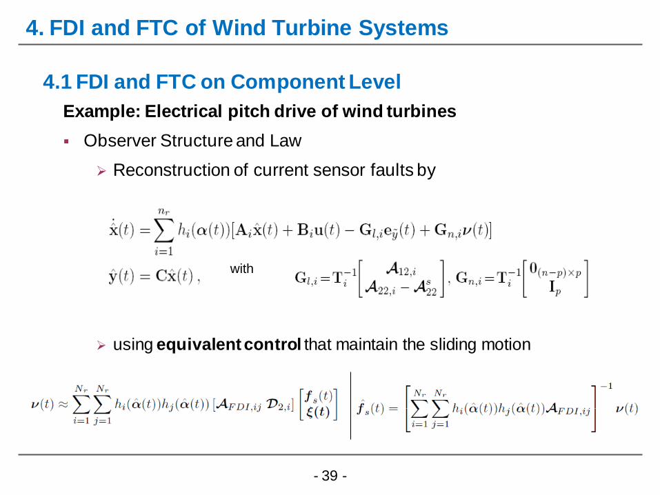
Example: Electrical pitch drive of wind turbines
Observer Structure and Law
Reconstruction of current sensor faults by
using equivalent control that maintain the sliding motion
4.1 FDI and FTC on Component Level
with

- 40 -
4. FDI and FTC of Wind Turbine Systems
Example: Electrical pitch drive of wind turbines
Results for a 1.2 MW turbine
4.1 FDI and FTC on Component Level
uncertainty load bounds
linear observer gain : sliding mode gain:
- 41 -
0 0.2 0.4 0.6 0.8 1 1.2 1.4 1.6-200
-150
-100
-50
0
t [s]
I sd [
A]
0 0.2 0.4 0.6 0.8 1 1.2 1.4 1.6-200
-100
0
100
200
t [s]
I sq [
A]
0 0.2 0.4 0.6 0.8 1 1.2 1.4 1.6-4
-2
0
2
4
x 104
t [s]
TL [
Nm
]
y1
y1hat
y2
y2hat
TL
TLhat
4. FDI and FTC of Wind Turbines Systems
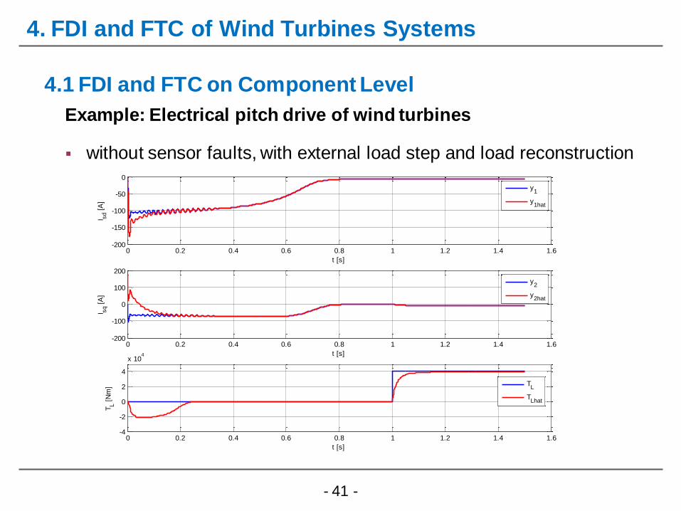
Example: Electrical pitch drive of wind turbines
4.1 FDI and FTC on Component Level
without sensor faults, with external load step and load reconstruction
- 42 -
0 0.2 0.4 0.6 0.8 1 1.2 1.4 1.6-50
0
50
t [s]
1
0 0.2 0.4 0.6 0.8 1 1.2 1.4 1.6-100
0
100
t [s]
2
0 0.2 0.4 0.6 0.8 1 1.2 1.4 1.6-100
0
100
t [s]
3
0 0.2 0.4 0.6 0.8 1 1.2 1.4 1.6-0.5
0
0.5
t [s]
4
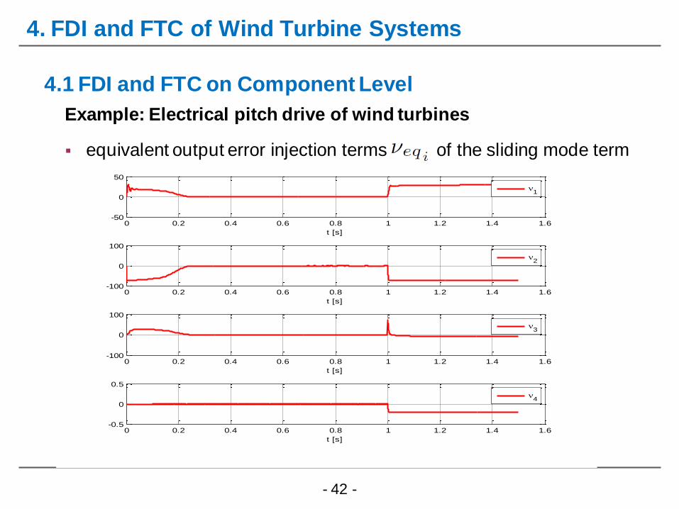
4. FDI and FTC of Wind Turbine Systems
Example: Electrical pitch drive of wind turbines
4.1 FDI and FTC on Component Level
equivalent output error injection terms of the sliding mode term
- 43 -
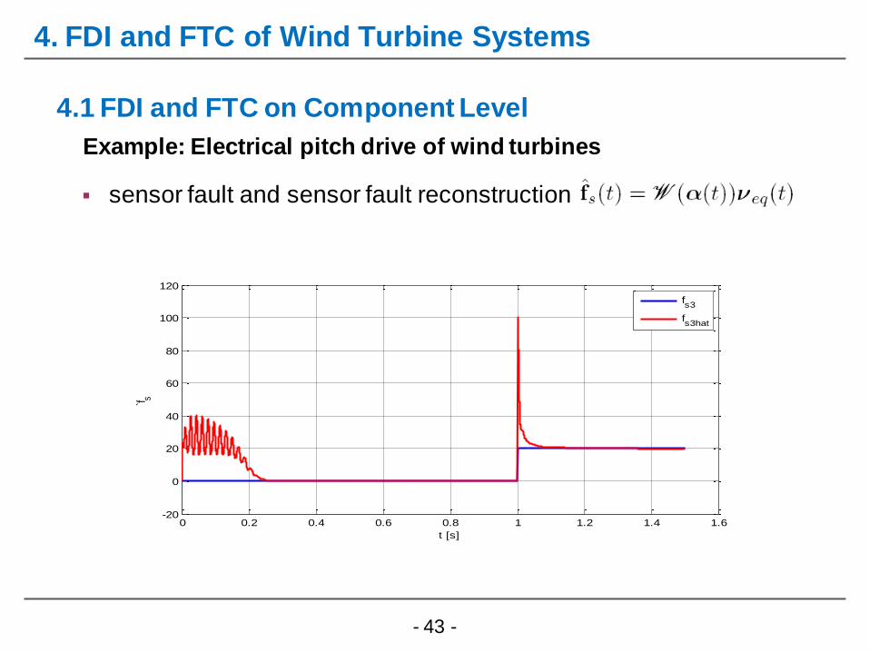
4. FDI and FTC of Wind Turbine Systems
Example: Electrical pitch drive of wind turbines
4.1 FDI and FTC on Component Level
sensor fault and sensor fault reconstruction
0 0.2 0.4 0.6 0.8 1 1.2 1.4 1.6-20
0
20
40
60
80
100
120
t [s]
`f s
fs3
fs3hat
- 44 -
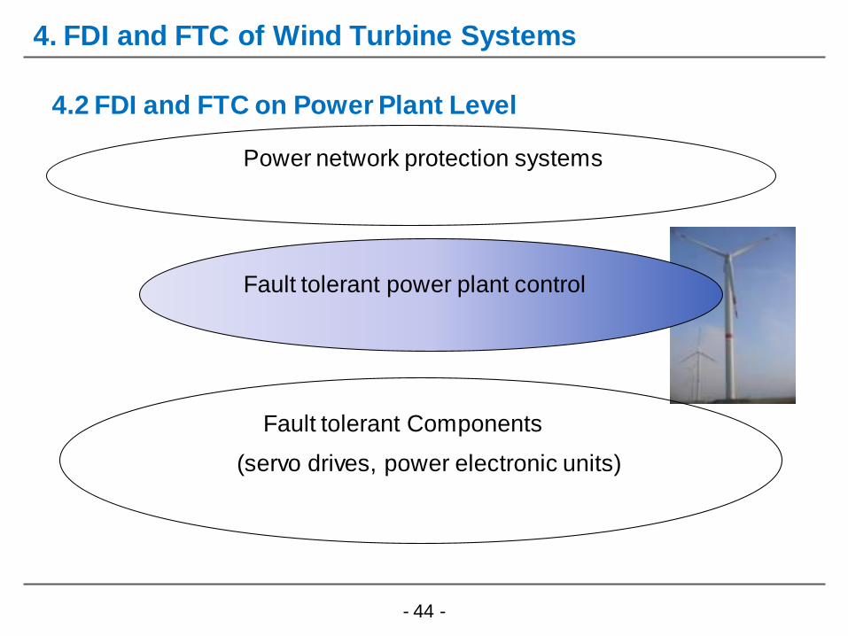
Fault tolerant Components
(servo drives, power electronic units)
Fault tolerant power plant control
Power network protection systems
4.2 FDI and FTC on Power Plant Level
4. FDI and FTC of Wind Turbine Systems
- 45 -
4. FDI and FTC of Wind Turbine Systems
4.2 FDI and FTC on Power Plant Level
Objectives
Partial- / full-load region
Baseline Controller
FTC scheme
Results
- Simulation with Hardware-In-the Loop test-bed
- 46 -
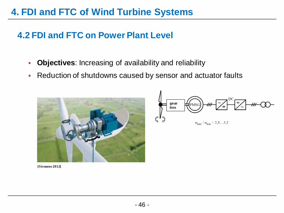
4. FDI and FTC of Wind Turbine Systems
4.2 FDI and FTC on Power Plant Level
Objectives: Increasing of availability and reliability
Reduction of shutdowns caused by sensor and actuator faults
[Siemens 2012]
gear
box
- 47 -
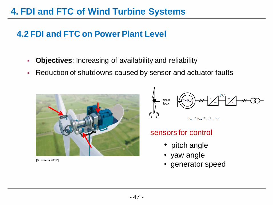
4. FDI and FTC of Wind Turbine Systems
4.2 FDI and FTC on Power Plant Level
Objectives: Increasing of availability and reliability
Reduction of shutdowns caused by sensor and actuator faults
[Siemens 2012]
sensors for control
• pitch angle
• yaw angle
• generator speed
gear
box

- 48 -
4. FDI and FTC of Wind Turbine Systems
4.2 FDI and FTC on Power Plant Level
Objectives: Increasing of availability and reliability
Reduction of shutdowns caused by sensor and actuator faults
[Siemens 2012]
actuators for control
• pitch drives (full load)
• generator (partial load)
gear
box
- 49 -
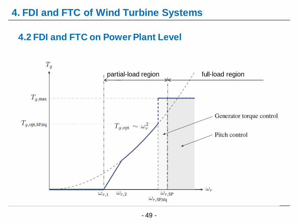
4. FDI and FTC of Wind Turbine Systems
4.2 FDI and FTC on Power Plant Level
partial-load region full-load region

- 50 -
4. FDI and FTC of Wind Turbine Systems
4.2 FDI and FTC on Power Plant Level
Baseline controller
Generator/
converter
Tg,d
Wind turbine
- 51 -
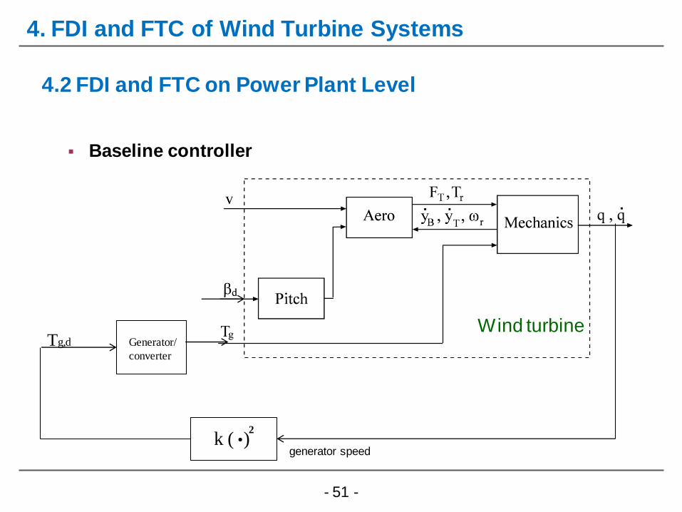
4. FDI and FTC of Wind Turbine Systems
4.2 FDI and FTC on Power Plant Level
Baseline controller
Generator/
converter
Tg,d
Wind turbine
k ( ) generator speed
2 .

- 52 -
4. FDI and FTC of Wind Turbine Systems
4.2 FDI and FTC on Power Plant Level
Baseline controller
Generator/
converter
Tg,d
Wind turbine
k ( )
Gain-Scheduling
Control
generator speed
2 .
generator speed
GV: pitch angle

- 53 -
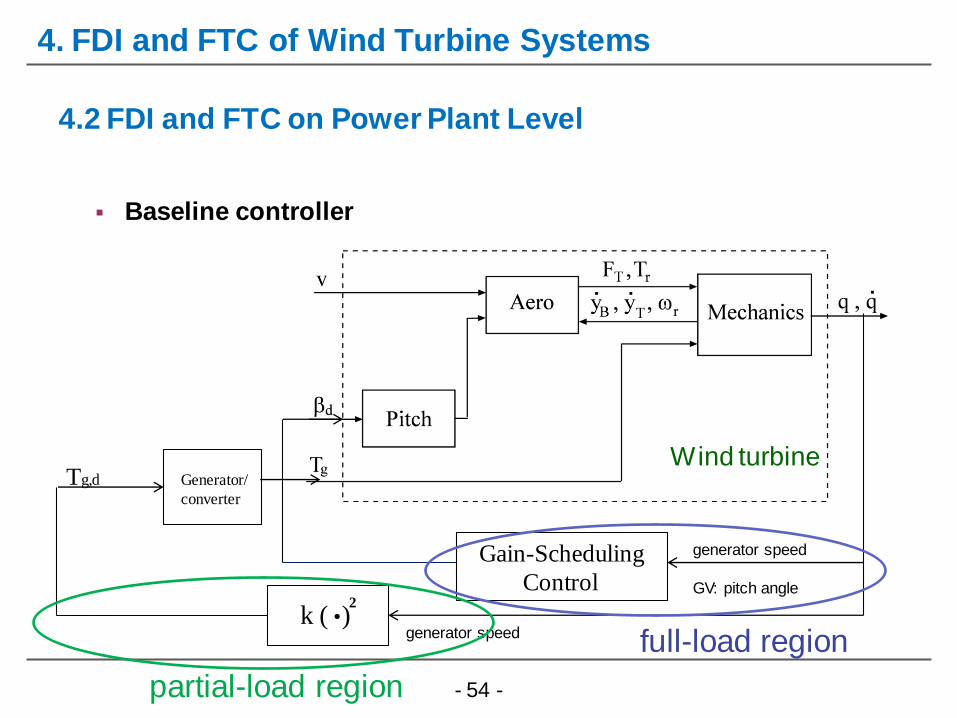
4. FDI and FTC of Wind Turbine Systems
4.2 FDI and FTC on Power Plant Level
Baseline controller
Generator/
converter
Tg,d
Wind turbine
k ( )
Gain-Scheduling
Control
generator speed
2 .
generator speed
GV: pitch angle
partial-load region
- 54 -
4. FDI and FTC of Wind Turbine Systems
4.2 FDI and FTC on Power Plant Level
Baseline controller
Generator/
converter
Tg,d
Wind turbine
k ( )
Gain-Scheduling
Control
generator speed
2 .
generator speed
GV: pitch angle
full-load region
partial-load region
- 55 -
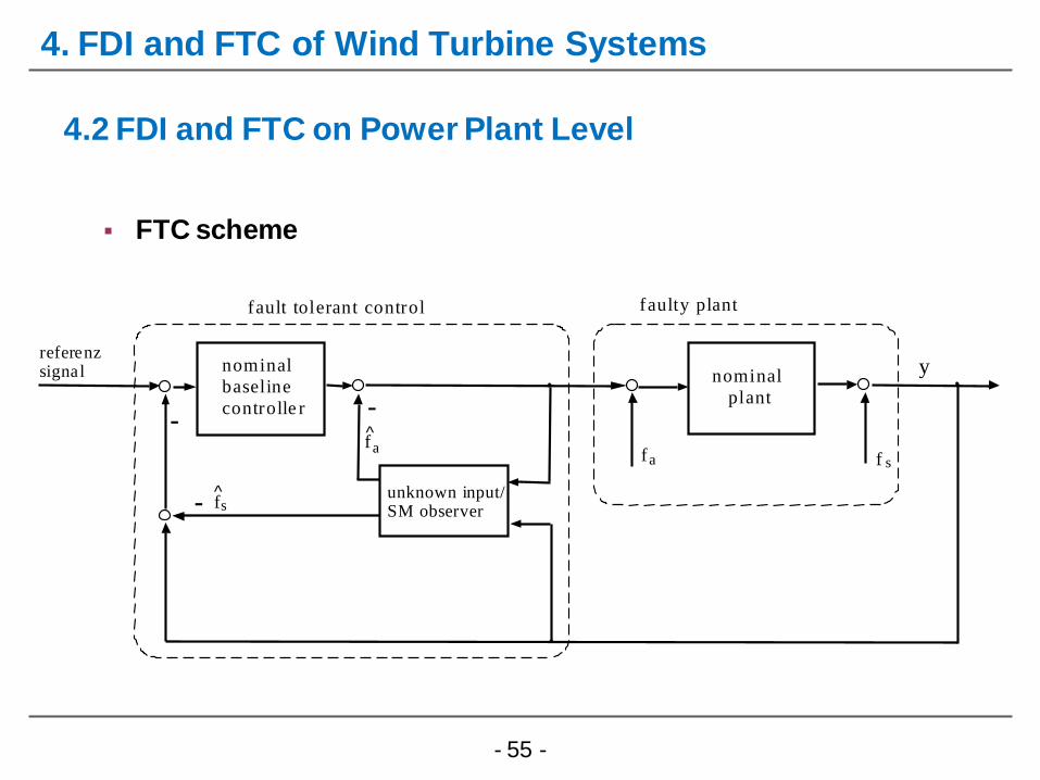
4. FDI and FTC of Wind Turbine Systems
4.2 FDI and FTC on Power Plant Level
FTC scheme
a f
s
y r e f e r e n z s i g n a l
n o m i n a l
b a s e l i n e
c o n t r o l l e r -
n o m i n a l
p l a n t
f
f a u l t t o l e r a n t c o n t r o l
u n k n o w n i n p u t / S M o b s e r v e r
s f a f
f a u l t y p l a n t
-
-

- 56 -
4. FDI and FTC for Renewable Energy Systems
4.2 FDI and FTC on Power Plant Level
Results: Simulation with Hardware-In-the Loop test-bed

- 57 -
4. FDI and FTC for Renewable Energy Systems
4.2 FDI and FTC on Power Plant Level
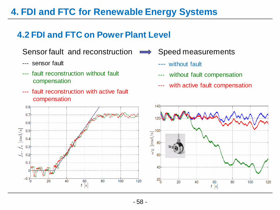
Experimental design
generator speed sensor fault
five different measurements over 120 s period
simulated turbulent wind speed with mean value 18 m/s
/ TS fuzzy gain-scheduling controller (full-load region)
Test cases
without fault
without fault compensation
with active compensation:
- 58 -
4. FDI and FTC for Renewable Energy Systems
4.2 FDI and FTC on Power Plant Level
Sensor fault and reconstruction
--- sensor fault
--- fault reconstruction without fault
.compensation
--- fault reconstruction with active fault
.compensation
Speed measurements
--- without fault
--- without fault compensation
--- with active fault compensation
- 59 -
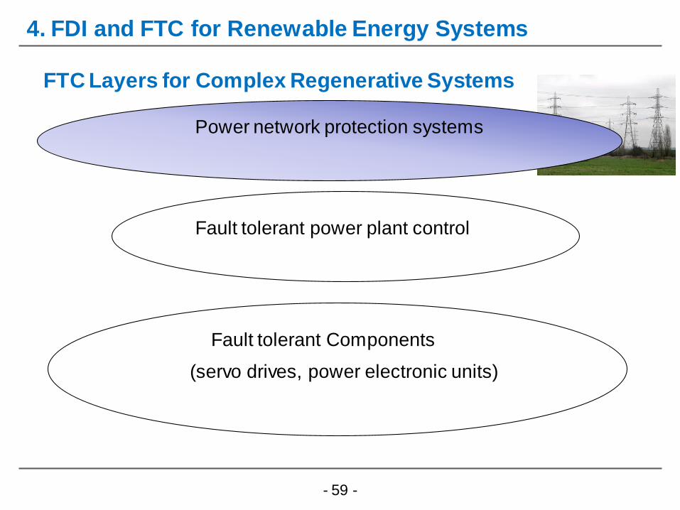
FTC Layers for Complex Regenerative Systems
Fault tolerant Components
(servo drives, power electronic units)
Fault tolerant power plant control
Power network protection systems
4. FDI and FTC for Renewable Energy Systems
- 60 -
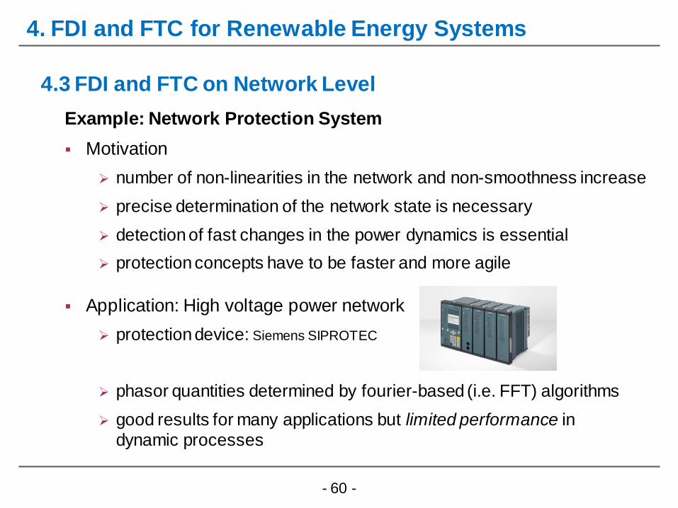
4. FDI and FTC for Renewable Energy Systems
Example: Network Protection System
Motivation
number of non-linearities in the network and non-smoothness increase
precise determination of the network state is necessary
detection of fast changes in the power dynamics is essential
protection concepts have to be faster and more agile
Application: High voltage power network
protection device: Siemens SIPROTEC
phasor quantities determined by fourier-based (i.e. FFT) algorithms
good results for many applications but limited performance in
dynamic processes
4.3 FDI and FTC on Network Level

- 61 -
4. FDI and FTC for Renewable Energy Systems
Example: Network Protection System
Approach: Prony‘s method
Mathematical model of the power network is unknown
state and parameter estimation by observer techniques is not feasible
measurements are locally available
Prony’s method is a kind of system identification
model structure selection by validation criteria
black box model but physical interpretable parameters
4.3 FDI and FTC on Network Level

- 62 -
4. FDI and FTC for Renewable Energy Systems
Example: Network Protection System
Approach: Prony‘s method
4.3 FDI and FTC on Network Level
- 63 -
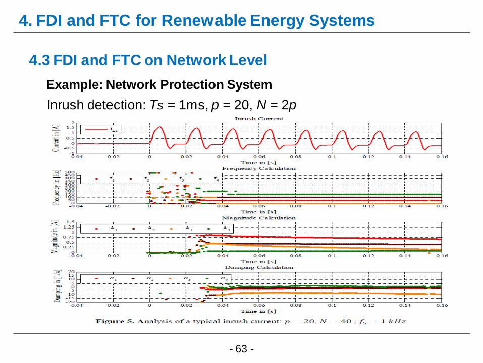
4. FDI and FTC for Renewable Energy Systems
Example: Network Protection System
4.3 FDI and FTC on Network Level
Inrush detection: Ts = 1ms, p = 20, N = 2p

- 64 -
4. FDI and FTC for Renewable Energy Systems
4.3 FDI and FTC on Network Level
Inrush detection
General, power system faults consists
of a large ratio of fundamental freq.
Model order selection is important
p = 20, N = 2p
Second harmonic is an appropriate
indicator to detect inrush events
robust detection time is 40 ms
faster as FFT based signal processing
40ms
Example: Network Protection System

- 65 -
4. Conclusion
FDI /FTC scheme for renewable energy systems were presented
Problem was decomposed into three different levels
3 examples of FDI and FTC are discussed in detail
Conclusion
Current and Future Work
RE systems such as wind turbines and PV have to support the
power network like conventional power plant with huge inertia
Output only FDI using machine learning methods
Papers and reports: www.researchgate.net/profile/Horst_Schulte2
- 66 -
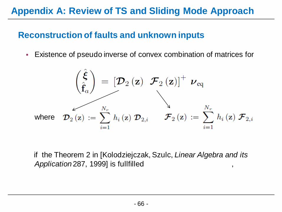
Existence of pseudo inverse of convex combination of matrices for
where
if the Theorem 2 in [Kolodziejczak, Szulc, Linear Algebra and its
Application 287, 1999] is fullfilled ,
Reconstruction of faults and unknown inputs
Appendix A: Review of TS and Sliding Mode Approach
- 67 -
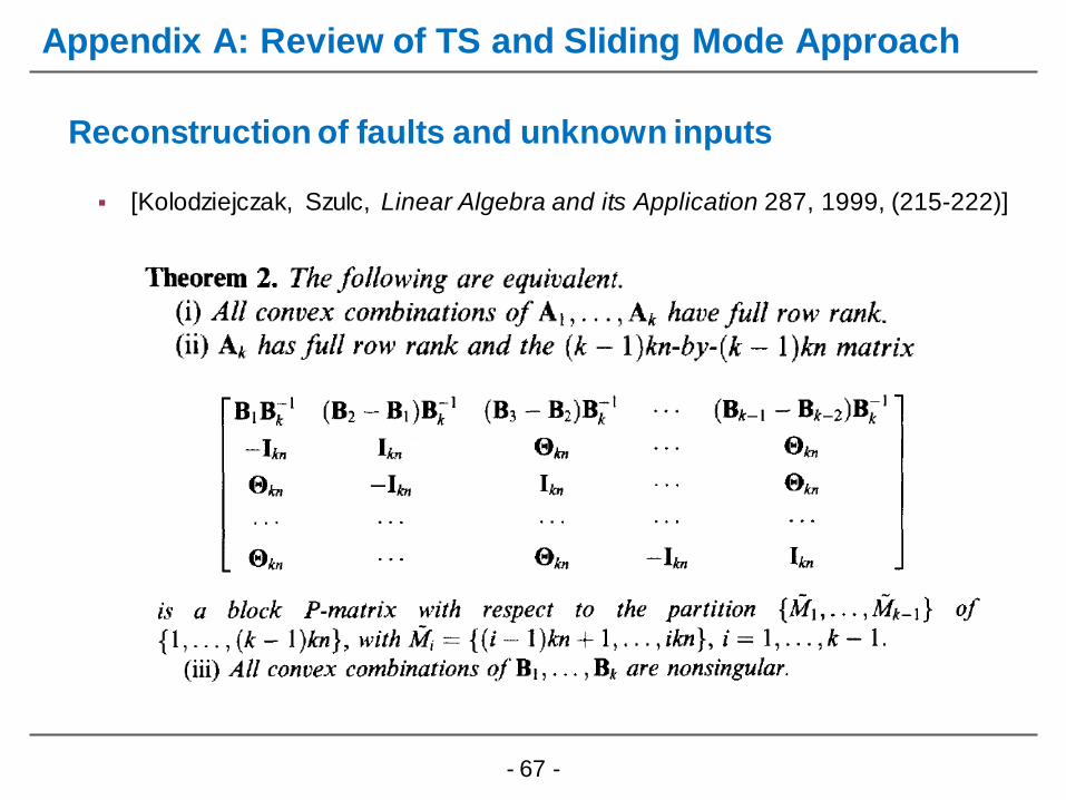
[Kolodziejczak, Szulc, Linear Algebra and its Application 287, 1999, (215-222)]
Reconstruction of faults and unknown inputs
Appendix A: Review of TS and Sliding Mode Approach