Fault current contribution from PPMS & HVDC - entsoe.eu codes documents/NC RfG... · Fault current...
15
ENTSO-E AISBL • Avenue de Cortenbergh 100 • 1000 Brussels • Belgium • Tel + 32 2 741 09 50 • Fax + 32 2 741 09 51 • [email protected] • www. entsoe.eu Fault current contribution from PPMS & HVDC ENTSO-E guidance document for national implementation for network codes on grid connection 16 November 2016
-
Upload
duongnguyet -
Category
Documents
-
view
244 -
download
5
Transcript of Fault current contribution from PPMS & HVDC - entsoe.eu codes documents/NC RfG... · Fault current...

ENTSO-E AISBL • Avenue de Cortenbergh 100 • 1000 Brussels • Belgium • Tel + 32 2 741 09 50 • Fax + 32 2 741 09 51 • [email protected] • www. entsoe.eu
Fault current contribution from PPMS & HVDC
ENTSO-E guidance document for national
implementation for network codes on grid connection
16 November 2016
Fault current contribution from PPMS & HVDC
ENTSO-E AISBL • Avenue de Cortenbergh 100 • 1000 Brussels • Belgium • Tel + 32 2 741 09 50 • Fax + 32 2 741 09 51 • [email protected] • www. entsoe.eu
2
Table of Contents DESCRIPTION ............................................................................................................................................3
Code(s) & .................................................................................................................................................3
Introduction ..............................................................................................................................................3
NC frame ..................................................................................................................................................4
Further info ...............................................................................................................................................4
INTERDEPENDENCIES ............................................................................................................................5
Between the CNCs ...................................................................................................................................5
With other NCs .........................................................................................................................................5
System characteristics ..............................................................................................................................5
Technology characteristics .......................................................................................................................9
COLLABORATION ..................................................................................................................................13
TSO – TSO .............................................................................................................................................13
TSO – DSO ............................................................................................................................................13
RSO – Grid User ....................................................................................................................................13

Fault current contribution from PPMS & HVDC
ENTSO-E AISBL • Avenue de Cortenbergh 100 • 1000 Brussels • Belgium • Tel + 32 2 741 09 50 • Fax + 32 2 741 09 51 • [email protected] • www. entsoe.eu
3
DESCRIPTION
Code(s) &
Article(s)
NC RfG - Articles: 20 2 (b) and (c);
NC HVDC - Article 19
Introduction
This IGD will give guidance on the background of fast fault current contribution. It will
divide the fault incidents in different phases and give the system needs in these phases
considering the grid topology. The influence of reaction to unbalanced faults is pointed
out. However, the IGD will not recommend exact values for parameter related to fast fault
current contribution.
As a result of conventional power units displacement, the total contribution to system
faults will decrease further with voltage sensitivity, increasing if no other measures are
taken in the system. Reactive current injection during faults helps to both recovering the
voltage during faults and to injecting enough current quickly enough for system
protections to function reliably. Both of these aspects which are part of the performance
aspects of fault-ride-through family of requirements are essential to wider system
stability.
The time period for current injection can be divided into 3 parts:
A Immediately after the fault, while the main transmission system protections are
measuring, e.g. 0-40ms.
B The remainder part of the fault duration until fault clearance.
C Immediately following fault clearance.
For period A the foremost transmission system objective is to ensure adequate magnitude
of current to allow protection to detect the fault both fast and selectively. For this period
making a large enough contribution is more important than delivering to an exact
magnitude target. To achieve the highest speed, a distinction between real and reactive
current injection components may not be practical.
For period B the foremost transmission system objective is to boost the voltage as much
as possible to aid generator stability. Again high magnitude rather than meeting an exact
magnitude targets is the key consideration, as long as the voltage remains low (e.g. below
normal voltage operating range).
For period C the foremost objective in large systems (with substantial total inertia) is to
restore system voltage towards the target voltage, limiting the voltage target overshoot
and achieving a reasonably short settling time.
For small synchronous areas (SAs) and for systems with little and diminishing total
inertia, real current injection to contribute towards frequency stability may be a
consideration in period C (even before voltage settling time) and may even be a
consideration in period B in the smallest SAs.
Regarding radial networks a fast fault current contribution of NSG that is located
downstream of a fault might lead to two effects. On the one hand the fault current
contribution of the NSG may reduce the fault current from the upstream network and
protection devices might not recognise fault conditions and isolate the faulted part of the
grid. On the other hand fault current contribution from downstream parts of the circuit-
breaker may lead to delayed fault clearing since the fault current may maintain the fault.

Fault current contribution from PPMS & HVDC
ENTSO-E AISBL • Avenue de Cortenbergh 100 • 1000 Brussels • Belgium • Tel + 32 2 741 09 50 • Fax + 32 2 741 09 51 • [email protected] • www. entsoe.eu
4
The nature of and scale of the problems associated with absence of short circuit current
contribution provided by Power Electronics (PE), such as Power Park Modules (PPMs)
and HVDC converters, during and directly after the fault depends on the location of the
short circuit and the characteristic of the local grid (e.g. onshore/offshore grid, long/short
AC connections, local grid with surplus of generation or surplus of consumption). Taking
these aspects into account any requirements regarding this issue should ideally be
considered for each network area. It may even be necessary to vary requirements locally.
However, it may not be practical to implement such fine tuning of the requirement, due to
engineering resource implications, including those of DSOs (and possibly also TSOs).
The requirement is a valuable balance between a clear statement of the common
developing system needs (driven by increases in renewable energy sources (RES)
penetration) and opportunities to build on national existing arrangements, particularly for
the less severe asymmetrical faults (which have less widespread impact, but occur more
numerous), without prescribing detailed technical specifications or implementations.
System conditions during a fault need to be carefully considered together with
requirements for reactive power control modes (IGD Reactive power control mode)) and
active power recovery (IGD Post fault active power recovery).
The requirement is specific for power park modules or HVDC systems connected to
distribution or transmission networks to deliver an adequate reactive current injection
during short circuits and after fault clearing when the voltage has not recovered. The
objective of this requirement is to limit the consequences of a short circuit with regards to
unwanted operation of protection devices and to stabilize the voltage after secured faults
on transmission level. As in case of a fault on the transmission system level a voltage drop
will propagate across large geographical areas around the point of the fault during the
period of the fault. The increased levels of distributed generation (including Type B
generators) must add value to such conditions.
NC frame
According to Article 20 of NC RfG type B (and above by default) power generating
modules shall be capable of providing a fast fault current. The relevant TSO shall have the
right to specify the:
characteristics, timing and accuracy of the fast fault current
interdependency between fast fault reactive current injection requirements and
active power recovery
Furthermore, according to article 19.2 of NC HVDC, if specified by the relevant TSO,
HVDC systems shall have the capability to provide fast fault current.
Further info [1] KEMA: “Technical report on ENTSOE Network Code: Requirements for generators”,
https://ec.europa.eu/energy/sites/ener/files/documents/KEMA_Final%20Report_RfG%20
NC.pdf
[2] Muljadi, E., Gevorgian, V., et al: “Short circuit current contribution for different wind
turbine generator types” IEEE Power and Energy Society 2010 General Meeting,
Minneapolis, Minnesota, July 25–29, 2010
[3] Bolik, S. M.: “The impact of Grid Codes on the development of wind turbine
technologies”, Proceedings of 7th international workshop large-scale integration wind
power into power system. Madrid, Spain; 2008
[4] Erlich, I.:” Effect of wind turbine output current during the faults on grid voltage and

Fault current contribution from PPMS & HVDC
ENTSO-E AISBL • Avenue de Cortenbergh 100 • 1000 Brussels • Belgium • Tel + 32 2 741 09 50 • Fax + 32 2 741 09 51 • [email protected] • www. entsoe.eu
5
the transient stability of wind parks”, Proceedings of Power & Energy Society General
Meeting, July 2009
[5] Fortmann, J., Pfeiffer, R., Martin, F., et al: “The FRT requirements for wind power
plants in the ENTSO-E Network Code on Requirements for Generators”, Proceedings of
12th International Workshop on Large-scale Integration of Wind Power into Power
Systems as well as on Transmission Networks for Offshore Wind Power Plants, October
2013, London
[6] Fortmann, J, Pfeiffer, R. et al: ”FRT requirements for wind power plants in the
ENTSOE network code on requirements for generators”, IET Renewable Power
Generation, Volume 9, Issue 1, January 2015
[7] Erlich, I., et al: ”Dynamic behavior of offshore wind farms with AC grid connection”,
Proceedings of 7th International Workshop on Large Scale Integration of Wind Power and
on Transmission Networks for Offshore Wind Farms, Madrid, Spain, 2008
[8] Kühn, H.: Strom- und Spannungsquellen im Netz, Omicron Anwendertagung 2012
[9] Erlich, I., Winter, W., et al: “Advanced Grid Requirements for the Integration of Wind
Turbines into the German Transmission System”, 6th International Workshop on Large-
scale Integration of Wind Power and Transmission Networks for Offshore Wind Farms,
Delft, The Netherlands, 2006
[10] Li, R., Booth, C., Urdal, H., et al: “A systematic evaluation of network protection
responses in future converter-dominated power systems”, 13th International Conference
on Development in Power System Protection 2016 (DPSP), Edinburgh, United Kingdom,
2016
[11] Urdal, H., Martinez Villanueva, S., Kilter, J., Jahn, J., Sprooten, J., Baranauskas, A.:
“Future System Challenges in Europe. Contributions to Solutions from Connection
Network Codes.”, CIGRÉ USNC International Colloquium Evolution of Power System
Planning to Support Connection of Generation, Distributed Resources and Alternative
Technologies, Philadelphia, United States of America, 2016
[12] Roscoe, Andrew J., et al: “A VSM (Virtual Synchronous Machine) Converter
Controls Model Suitable for RMS Studies for Resolving System Operator / Owner
Challenges” (WIW16-217), 15th international workshop on large-scale integration of wind
power into power systems as well as on transmission networksfor offshore wind power
plants, Vienna, Austria, 2016
[13] Ierna, R., et al: “Effects of VSM Converter Control on Penetration Limits of Non-
Synchronous Generation in the GB Power System”( WIW16-218 ), 15th international
workshop on large-scale integration of wind power into power systems as well as on
transmission networksfor offshore wind power plants, Vienna, Austria, 2016
INTERDEPENDENCIES
Between the
CNCs
NC RfG
NC HVDC
With other NCs
No interdependencies with other NCs
System
characteristics
The below two figures and text are extracted from the international conference
“International Workshop on Large-scale Integration of Wind Power into Power
Systems” (October 2013). The joint TSO / Manufacturers’ presentation [5] was based
on a joint paper with multiple wind manufacturers and TSOs as well as ENTSO-E
and EWEA (European Wind Energy Association).

Fault current contribution from PPMS & HVDC
ENTSO-E AISBL • Avenue de Cortenbergh 100 • 1000 Brussels • Belgium • Tel + 32 2 741 09 50 • Fax + 32 2 741 09 51 • [email protected] • www. entsoe.eu
6
The diagram below illustrate typical response of a synchronous generator to a 3-
phase fault in periods A, B and C (defined by the vertical lines).
Blue: Instantaneous value of generator reactive current.
Green: positive sequence value
• Initial period of a fault (Phase A): Delivery of a fault current within
20 ms to recognize, locate and initiate clearance of the fault by electrical
protection systems.
• Later period of the fault (Phase B): Delivery of (additional) reactive current
supporting voltage retention. Magnitude of current prevails over control
accuracy. After fault clearance (Phase C): Delivery of a reactive current to
restore voltage and restoration of active power to remove power imbalances
and corresponding frequency deviations. Control accuracy is crucial to avoid
over-voltages.
Measurement challenges, particularly for period A: Positive sequence versus
instantaneous:
Evaluation of 3-phase-measurements:
0 0.125 0.25 0.375 0.5 0.625 0.75 0.875 1-2
-1
0
1
2
3
4
5
I Q,M
V/I
n (
p.u
.)
t (s)
-0.04 -0.03 -0.02 -0.01 0 0.01 0.02 0.03 0.04-1
-0.5
0
0.5
1
Inst. p
hase
curre
nts (p
.u.)
t (s)
-0.04 -0.03 -0.02 -0.01 0 0.01 0.02 0.03 0.040
0.2
0.4
0.6
0.8
1
i Q (p.u.
)
t (s)

Fault current contribution from PPMS & HVDC
ENTSO-E AISBL • Avenue de Cortenbergh 100 • 1000 Brussels • Belgium • Tel + 32 2 741 09 50 • Fax + 32 2 741 09 51 • [email protected] • www. entsoe.eu
7
Voltages and currents can be described e.g. by instantaneous values or sequence
components.
• Instantaneous values: magnitude of space vector. Only useful for balanced
faults.
• Sequence values: evaluation over one fundamental frequency period. This is
the default requirement in the NC RfG. Applicable to all faults.
• Time Restrictions: Using a sequence based evaluation, a response faster than
20 ms is not possible.
The presentation further contained the following Wind Power Plant (WPP)
viewpoint:
Phase A – initial period of fault:
Fault Current Injection - Challenges for WPP
The NC RfG refers to positive sequence values. This excludes implementation of
controlled action in less than 20 ms. Further time for initiation of control action and
resulting WPP response needs to be allowed for as well.
What should be defined:
The NC RfG shall not introduce barriers to certain technologies. Flexibility is in
particular needed with regard to the fault current injection during Phase A.
Voltage support - WPP viewpoint
Phase B – later period of fault:
Challenges for WPP
Accuracy requirements of WPPs (partially) coupled directly to the grid (doubly fed
induction generators, DFIGs) are deemed not critical and need to be compared to
synchronous generators.
Exceeding the minimum requirements for fault current provision in a stable and
secure way is fully compliant.
Phase C – after fault clearance:
Challenges for WPP
Accuracy is of major importance only during Phase C to avoid over-voltages.
Especially in “weak” networks and/or under rules for strong reactive current
provision during a fault, voltage transients at the beginning of Phase C can become
an issue.
End of quote from Wind Integration Workshop 2013.
System characteristics relevant to fast fault contribution and generation mix have
significant impact on inter alia
voltage control mode implementation

Fault current contribution from PPMS & HVDC
ENTSO-E AISBL • Avenue de Cortenbergh 100 • 1000 Brussels • Belgium • Tel + 32 2 741 09 50 • Fax + 32 2 741 09 51 • [email protected] • www. entsoe.eu
8
voltage stability
voltage recovery after fault clearance
operation of protection devices
negative sequence if required for national implementation
and should be taken into account reasonably by the relevant TSO when selecting the
fast fault current parameters within the frames given in NC RfG and NC HVDC.The
following paragraphs will describe the situation for TSO and other meshed networks.
Radial networks will be covered later on.
Fast fault current contribution is important in order to restore the pre-fault operation
after fault clearance. For this fast fault contribution should support as well the
voltage after fault clearing in combination with the slower voltage control modes.
The requirement for fast fault current contribution can either be fulfilled at the
connection point or the terminals of the individual generator since signal
transmission might not be possible due to the required dynamics. The relative priority
of restoring the reactive power and voltage versus real power and frequency depends
upon the system size, predominantly of the synchronous area (see IGD Post fault
active power recovery). For smaller synchronous areas (with less system inertia, and
higher frequency sensitivity than larger areas) the active power restoration is
particular time critical, in order to avoid reaching a system frequency following a
large sudden power imbalance which results in demand disconnection. For larger
synchronous areas, a moderate active power recovery after a cleared fault may be
sufficient and the emphasis may be laid on the post fault reactive power support. The
provision of reactive current supports the grid voltage, provision of active current
will help to stabilize the frequency in the system.
Regarding required time to deliver a contribution in Phase A, an earlier draft of RfG
(about 2012) defined the longest time before starting to deliver fast fault current as
10ms. This was justified based on anticipated problems of adequate protection
performance. In particular linked to extreme cases of non-synchronous generation
penetration in comparison to demand. In Denmark this penetration has already
exceeded 100% and several other countries anticipate in their future energy scenarios
operating conditions exceeding 100%, even for a full synchronous area (prior to
constraining off actions, e.g. GB>150% in the most challenging hour for 2030). At
the time the manufacturing industry responded strongly against the 10ms parameter
and it was withdrawn for determination in individual countries.
The manufacturers also challenged the lack of evidence for the 10 ms need. In
response R&D work was initiated, in particular by National Grid. This R&D
(focused on University of Strathclyde) is still in progress. A paper focused on the
extreme case of 100% NSG [10] generation was published in 2016. Its main focus
has been on operating time and accuracy of distance protection when the system is
weak. It demonstrates that protection operating times may increase dramatically (e.g.
from 10-20ms to >100ms) if the current injection is much delayed. It also
demonstrates some impact (but less than on operating time) on effective reach of the
distance protection.
In radial networks current protection schemes may isolate a fault by opening an
upstream circuit breaker only (e. g. definite time-deal overcurrent protection). In this
case all generators that are connected downstream of this circuit breaker would

Fault current contribution from PPMS & HVDC
ENTSO-E AISBL • Avenue de Cortenbergh 100 • 1000 Brussels • Belgium • Tel + 32 2 741 09 50 • Fax + 32 2 741 09 51 • [email protected] • www. entsoe.eu
9
possibly maintain the fault by supplying fault current. So it is important that the fault
is cleared when the circuit-breaker ist re-closed and the NSG can continue with
active power recovery to maintain frequency stability.
Technology
characteristics
Background:
Fast fault current contribution needs to be defined for non-synchronous equipment
such as Wind turbines with partial or full-size converter, Photovoltaics or HVDC
converters. Non-synchronous implying in this context that at least a portion of the
active power is fed to the grid via Power Electronics (PE). These devices can be
utilized very flexibly since their behaviour is predominantly determined via software
(performance by design). In contrast, synchronous generators react inherently to any
voltage deviation. Hence, they do not have to be considered regarding this
requirement.
Efforts have been made to distinguish between steady-state operation and fast fault
current contribution. Requirements on behaviour during voltage dips also impact on
behaviour after fault clearance, mainly active power recovery and transition to
voltage support during normal operation.
Classification:
Network codes usually distinguish between synchronous generator and all the rest
which is considered as non-synchronous. The vast majority of non-synchronous
generators use PE as interface to the grid. In case the full output power is delivered
via this PE interface only, this concept is referred to as full-size converter (FSC). The
electrical behaviour of such FSCs are predominantly determined by the PE interface,
its software and associated parameters. Due to common effectively FSC
characteristics, requirements for Wind Turbines (WT) with FSC, for PVs and even
for HVDC can be shared.
Within the PE interfaced PPMs the Doubly Fed Induction Generator (DFIG) takes on
a special position since only the rotor winding is grid interfaced by PE while the
stator winding of the induction machine is directly connected. In this concept the
inherent behaviour of an induction generator is combined with a programmed
behaviour of a converter at the terminals of such PPMs.
Fundamental capabilities and constraints of wind turbine generators (WTGs) and
Photovoltaic (PVs) based power stations and synchronous generators to withstand the
faults, remain connected and their contribution to support the grid during the faults
and directly after the faults (i.e. to provide active power recovery and/or reactive
power during/after the fault) are closely linked to the inherent technology features.
PE is sensitive to thermal overload and thermal capacity is rather low resulting in low
overload capability. For this reason injection of reactive current is possible within the
maximum current limits of the PE. Short-term overload capability (in the range of a
few hundreds of milliseconds) may be given depending on the PE layout and DC
behaviour during voltage dips.
Full-Size Converter (FSC)
The full scale converter totally decouples the DC power source from the grid. The
converter has to produce a reactive current based on network voltage measurements.
Due to the dynamic requirements measurement values can only be considered when

Fault current contribution from PPMS & HVDC
ENTSO-E AISBL • Avenue de Cortenbergh 100 • 1000 Brussels • Belgium • Tel + 32 2 741 09 50 • Fax + 32 2 741 09 51 • [email protected] • www. entsoe.eu
10
there they are transmitted without significant delay. Otherwise the terminal voltages
have to be used as reference.
This requires measurement, transmission of measurement values (if necessary),
calculation and control time. Regarding speed of initial response in phase A the
desired 10 ms response time (½ cycle) is considered challenging for most PPM full-
size converter systems, in many cases requiring significant changes to the design. For
phase B, reaching the target value with a high accuracy (e.g. 10 % within 60 ms) is
also controversial. Such tight specification is however unlikely to be needed until
phase C when a more generous settling time can be allowed. All responses are
controlled and need to be explicitly specified, but only as tight as is really justified. A
key issue is the definition of current for Phase A.
The main limitation is only converter size which also limits the short circuits
contribution of this type.
Partial Converter / DFIG
For generators with a direct connection of the stator winding of the rotating generator
to the grid, by nature of this connection, a voltage dip will automatically cause a
reactive current injection without delay. But the amplitude depends on the generator
characteristics and will decline within a few hundred milliseconds. When the voltage
is decreased, power park modules based on Double Fed Inductive Generator (DFIG)
(i.e. WTG with asynchronous generator, rotor converter and stator directly connected
to the grid), transiently provide the short circuit currents into the grid due to natural
asynchronous generator behaviour. The support to the grid is provided during the
first 10-30 ms following faults by discharging the magnetic field energy with the risk
of losing internal magnetization. The converter is able to control the current after the
period of some tens (50) of milliseconds and is able to feed in controlled currents
into the grid. However, the short circuit current decays faster than in case of
conventional power plants due to typical parameters of the induction generator on the
one side and the converter current control internal requirements to reduce the high
currents on the other. Without specific measures to protect against voltage dips and
the subsequent outrush currents a DFIG WTGs risks damage to its PE devices and
DC link capacitors due to resulting over-current and over-voltage on the rotor side.
But to solve this problem DFIG WTG are equipped with DC chopper systems. It
keeps the DC link parameters within an acceptable range by shunting the short circuit
current into a DC link resistor which dissipates the unbalance energy.
Reaction on unbalanced faults
RfG describes requirements on balanced faults. These faults are most critical in terms
of system stability, but unbalanced faults occur more numerous than balanced ones.
Article 20 (2)(c) enables the relevant system operator in coordination with the
relevant TSO to require for asymmetrical fast fault current. Requiring a defined
reaction to balanced faults could imply to use symmetric components and reacting
exclusively in the positive sequence since this will fulfil all requirements on balanced
faults. Regarding unbalanced faults fast fault current contribution in the positive
sequence only will be smaller since contribution in the negative sequence component
is missing. The foremost objective in meshed networks during phase A of getting a
fault current contribution that is as large as possible, will not be reached. The
foremost objective during phase B of boosting the voltage could result in undesired
over-voltages in the unaffected phase(-s). The strongest effect of fast fault current
contribution in terms of restoring voltage back to balanced conditions will be

Fault current contribution from PPMS & HVDC
ENTSO-E AISBL • Avenue de Cortenbergh 100 • 1000 Brussels • Belgium • Tel + 32 2 741 09 50 • Fax + 32 2 741 09 51 • [email protected] • www. entsoe.eu
11
achieved by an additional requirement in the negative sequence.
The zero sequence can be disregarded since usually at least one delta/wye
transformer will be found between the fault location and the generator terminals
which will eliminate the zero sequence component.
Symmetric components are based on complex rms values. Calculation of symmetric
components usually take per definition one period (20 ms in 50 Hz grids). This has to
be taken into account when defining requirements on rising and/or settling times and
accuracies for fast fault current contribution.
Main aspects to be considered for fast fault current contribution
In the NC RfG and NC HVDC there are requirements for the provision of fast fault
current injection.
In the NC RfG, TSOs have to specify requirements during and immediately after the
fault and in the NC HVDC, if specified by the relevant TSO, the HVDC shall have
the capability to provide fast fault current.
The main aspects to consider are:
1. Priority between real and reactive current
2. Different needs in different time periods of the fault, taking the grid
topology into account
3. Need for asymmetric contributions
4. Consideration of technological characteristics
1. Priority between real and reactive current
Further aspects are reported in relation to the content of IGD Post fault active power
recovery.
2. Different needs in different time periods of the fault
Representatives of TSOs and wind turbine manufacturers have agreed that the
challenge of finding suitable compromises between adequately covering the system
needs today and into the future of TSOs can best be achieved by detailed attention to
3 separate time periods:
Phase A First part of the fault duration, while transmission protection is most active,
e.g. first 40ms.
Phase B Remainder duration of the fault
Phase C After fault clearance
2A For phase A the main focus is to ensure adequate fault current for transmission
system protections. Investigations of protection performance under extreme high PE
penetration suggest requirements reflect highest possible amplitude, e.g. using the
full dynamic current capacity of the PE converters with least possible delay.
Magnitude accuracy is not important. Simple criterion, such as voltage below the
system operating range, may aid the speed of delivery. In this time period, it is
critical to avoid a simple focus on the normal definition of current, namely rms and
Fault current contribution from PPMS & HVDC
ENTSO-E AISBL • Avenue de Cortenbergh 100 • 1000 Brussels • Belgium • Tel + 32 2 741 09 50 • Fax + 32 2 741 09 51 • [email protected] • www. entsoe.eu
12
positive sequence. Criteria should not be defined in terms of sequence components,
but instead in phase voltages.
2B For Phase B the main focus is to support the system voltage at locations away
from the fault to support system stability. Again the high magnitude is important, but
accuracy of delivery is not, while the voltage remains below normal range. Use of
current definition in sequence components is fine.
2C For Phase C post fault clearance, the focus is on returning system voltage towards
normal range and to support power recovery. In this period the focus is on containing
voltage overshoot, meeting the magnitude target and achieving a reasonable settling
time contributing to system voltage settling.
During phases A and B the priority should be clearly set on the minimum time delay
and maximum magnitude for fast fault current contribution while accuracy of the
current angle is of subordinate importance.
Above mentioned behaviour is valid for meshed grids. Radial networks may –
depending on the protection schemes – require that the fault current contribution of
NSG should be as low as technically possible in order to clear the fault. This should
be taken into account when defining requirements for radial networks. This is a
prerequisite for these NSG to participate in phase C of the fault.
3. Need for asymmetric contributions
Providing asymmetric reactive current to contribute towards restoring balanced
voltages during faults is optional but highly recommended for systems with a
noticeable NSG penetration. The voltage during an unbalanced fault can only
“pushed” towards symmetry when both positive and negative sequence currents are
supplied. Feeding balanced fault current to unbalanced fault could result in too high
voltages in the phase(s) that are not affected by the fault. Zero sequence will be
blocked e. g. by delta/wye transformers which usually are installed on the way
between generator terminals and transmission grid. For this reason zero sequence
does not have to be considered. Furthermore referring only to the positive sequence
would result in less fault current contribution since the change of the positive
sequence in unbalanced faults is less than in balanced ones.
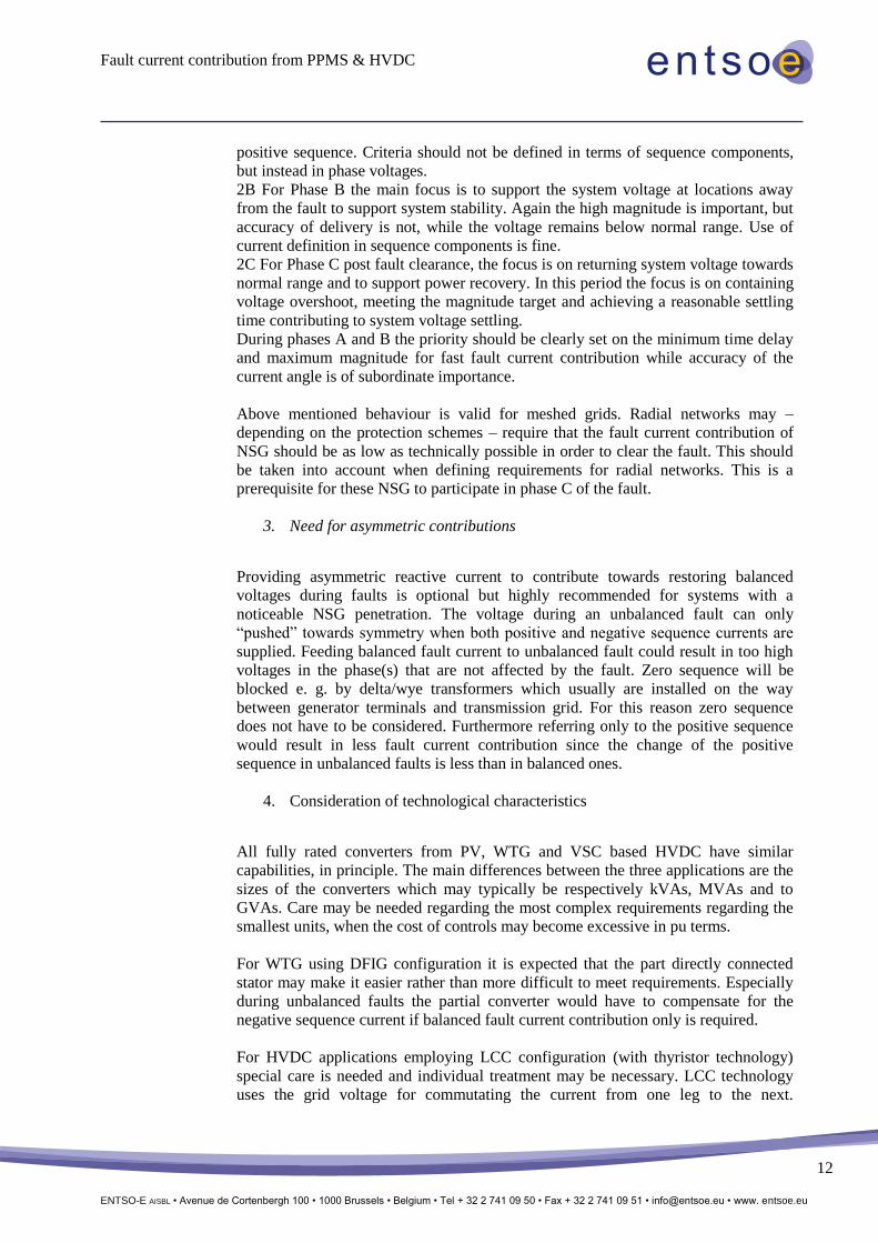
4. Consideration of technological characteristics
All fully rated converters from PV, WTG and VSC based HVDC have similar
capabilities, in principle. The main differences between the three applications are the
sizes of the converters which may typically be respectively kVAs, MVAs and to
GVAs. Care may be needed regarding the most complex requirements regarding the
smallest units, when the cost of controls may become excessive in pu terms.
For WTG using DFIG configuration it is expected that the part directly connected
stator may make it easier rather than more difficult to meet requirements. Especially
during unbalanced faults the partial converter would have to compensate for the
negative sequence current if balanced fault current contribution only is required.
For HVDC applications employing LCC configuration (with thyristor technology)
special care is needed and individual treatment may be necessary. LCC technology
uses the grid voltage for commutating the current from one leg to the next.

Fault current contribution from PPMS & HVDC
ENTSO-E AISBL • Avenue de Cortenbergh 100 • 1000 Brussels • Belgium • Tel + 32 2 741 09 50 • Fax + 32 2 741 09 51 • [email protected] • www. entsoe.eu
13
Distortions in the grid voltage or changes in its magnitude may lead to commutation
errors resulting in a complete blocking of the power flow. Furthermore this
technology shows a natural, non-controllable reactive power demand. Specific
reactive power requirements can be met by switching of external compensation. On
fault initiation (Phase A) the external compensation will inject a short discharge
current while the LCC HVDC outputs are being blocked. Afterwards the external
compensation will provide reactive power/current according to their characteristics at
the respective (reduced) voltage if not disconnected on the blocking of the HVDC.
COLLABORATION
TSO – TSO According to NC provisions RfG/HVDC TSO – TSO collaboration is not required.
TSO – DSO According to NC provisions RfG/HVDC TSO-DSO collaboration is required for
DSO connected PPMs and HVDC systems. This coordination should take into
account that the requirements to fast fault current contribution may differ with the
grid topology
RSO – Grid User According to NC provisions RfG/HVDC RSO – Grid Users collaboration is not
required.
Non-Exhaustive Requirement
Non-Mandatory
Requirement Article Applicability Parameters to be defined Definition
Fast fault current contribution
20(2)(b) NC
RfG B, C, D
Characteristics, timing and accuracy of fast fault current contribution including voltage deviation, reaction to asymmetrical faults
RSO in coordination
with the relevant TSO
Fast fault current contribution
19 NC HVDC
HVDC Systems Type B, C and C
of DC connected
PPM
Characteristics, timing and accuracy of fast fault current contribution including voltage deviation, reaction to asymmetrical faults
RSO in coordination
with the relevant TSO
Example(s):
Existing fast fault contribution requirements:
Existing requirements referring to fast fault current contributions vary across Europe. Below examples of
this requirement are specified can help to define this at the national level, although the fast moving system
characteristics makes it essential to have a fresh view of the needs:
In GB simple requirements go back to 2005, with the prime objective linked to frequency stability, the
determining factor in GB for the FRT requirements. In Germany but also in other countries it has been
required for PPMs to provide short circuit current during the fault in order to prevent unwanted operation of
protection and to stabilize the voltage during and after short circuits in the transmission system.

Fault current contribution from PPMS & HVDC
ENTSO-E AISBL • Avenue de Cortenbergh 100 • 1000 Brussels • Belgium • Tel + 32 2 741 09 50 • Fax + 32 2 741 09 51 • [email protected] • www. entsoe.eu
14
GB requirements:
When the system voltage drops below 90%, deliver without delay during the fault a current using the full
dynamic current capability. The requirement is simple, deliver the full capability when U<0.9 and return to
normal fast acting voltage control when U>0.9pu.
It was suggested by some commentators that this may be an unstable control arrangement, that instability
could result (system voltage oscillating around 0.9pu). This has not proved to be the case in numerous
installations over 10 years.
The component of the total current capability available to reactive current is in GB limited by a requirement
to continue during the fault duration the real component of current, with priority over reactive current. This
was introduced due to the greater concern for frequency instability. The largest loss for which reserves are
scheduled is made up from a single contingency loss, therefore having no spare reserves for simultaneous
loss of PPMs.
In practice, the GB requirement has been proven to have a significant legal weakness, lack of clarity in the
term “without delay during the fault duration”. This has been extensively misinterpreted as 60ms, very
different from the original intent made in context of normal target fault clearance time of 80ms.
Germany TSOs requirements:
Transmission Code 2007: 100 % of the required fault current 20 ms after fault detection (still in force but to
be replaced).
VDE AR-N-4120 TAR Hochspannung (HV directive, in force, currently under revision):
Rise time of the short-circuit current contribution < 30 ms, settling times < 60 ms in both positive and
negative sequence These requirements are considered as fulfilled, when the positive/negative sequence
values in the period of 30 – 50 ms (60 – 80 ms respectively) fulfill the requirements. Examples for
definition of rise time and settling time are given in VDE AR-N-4120.
Figure 1: Step response, rise and settling time
Rise time: Time between a setpoint step-change and the step response reaching a certain ratio (e. g. 90 %)
of the desired value for the first time.
Settling time: Time between a setpoint step-change and the step response entering the desired range of
tolerance (which may differ from 90 %) for the last time.
Minimum requirement 100 % of rated current at least in one phase. Priority to reactive current.
control variable x
rise timesettling time
time t
step change
step response x(t)
final steady-state value
transient overshoot
steady-state tolerance

Fault current contribution from PPMS & HVDC
ENTSO-E AISBL • Avenue de Cortenbergh 100 • 1000 Brussels • Belgium • Tel + 32 2 741 09 50 • Fax + 32 2 741 09 51 • [email protected] • www. entsoe.eu
15
In grids which are mainly radially structured or operated in open rings the NSG is required to limit the fault
current contribution in the fault phases A and B to their technical minimum. This applies to most MV
connected NSG that is not directly connected to the busbar of the MV/HV transformer.
But they have to stay connected to the grid in order to continue in-feed directly after fault clearanes (fault
phase C).
New approach to be implemented: Continuous Dynamic Grid Support
Many efforts have been taken to define the e. g. beginning and end of the fault. This could be simplified by
operating the Power Generating Units in such way that they react with the dynamics of fast fault current
contribution to any voltage change at their terminals. In combination with a plant controller that influences
the reference point for the amount of fast fault current in slower time frames a behaviour is created that is
more close to the behaviour of the synchronous generator with AVR. An example for such control scheme
is given in Figure 2.
Figure 2: Combination of steady-state voltage control and fast fault current contribution