Fatigue Reliability Evaluation of the Kiln Roller2009/section_07/07-28.pdf · Fatigue Reliability...
4
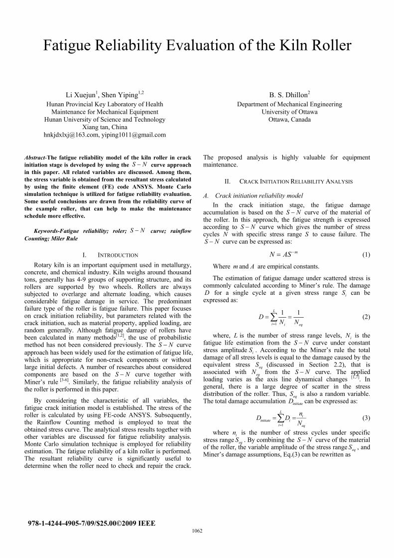
Fatigue Reliability Evaluation of the Kiln Roller Li Xuejun 1 , Shen Yiping 1,2 Hunan Provincial Key Laboratory of Health Maintenance for Mechanical Equipment Hunan University of Science and Technology Xiang tan, China [email protected], [email protected] B. S. Dhillon 2 Department of Mechanical Engineering University of Ottawa Ottawa, Canada Abstract-The fatigue reliability model of the kiln roller in crack initiation stage is developed by using the curve approach in this paper. All related variables are discussed. Among them, the stress variable is obtained from the resultant stress calculated by using the finite element (FE) code ANSYS. Monte Carlo simulation technique is utilized for fatigue reliability evaluation. Some useful conclusions are drawn from the reliability curve of the example roller, that can help to make the maintenance schedule more effective. S N − Keywords-Fatigue reliability; roler; curve; rainflow Counting; Miler Rule S N − I. INTRODUCTION Rotary kiln is an important equipment used in metallurgy, concrete, and chemical industry. Kiln weighs around thousand tons, generally has 4-9 groups of supporting structure, and its rollers are supported by two wheels. Rollers are always subjected to overlarge and alternate loading, which causes considerable fatigue damage in service. The predominant failure type of the roller is fatigue failure. This paper focuses on crack initiation reliability, but parameters related with the crack initiation, such as material property, applied loading, are random generally. Although fatigue damage of rollers have been calculated in many methods [1,2] , the use of probabilistic method has not been considered previously. The S N − curve approach has been widely used for the estimation of fatigue life, which is appropriate for non-crack components or without large initial defects. A number of researches about considered components are based on the S N − curve together with Miner’s rule [3-6] . Similarly, the fatigue reliability analysis of the roller is performed in this paper. By considering the characteristic of all variables, the fatigue crack initiation model is established. The stress of the roller is calculated by using FE-code ANSYS. Subsequently, the Rainflow Counting method is employed to treat the obtained stress curve. The analytical stress results together with other variables are discussed for fatigue reliability analysis. Monte Carlo simulation technique is employed for reliability estimation. The fatigue reliability of a kiln roller is performed. The resultant reliability curve is significantly useful to determine when the roller need to check and repair the crack. The proposed analysis is highly valuable for equipment maintenance. II. CRACK INITIATION RELIABILITY ANALYSIS A. Crack initiation reliability model In the crack initiation stage, the fatigue damage accumulation is based on the S curve of the material of the roller. In this approach, the fatigue strength is expressed according to S N − N − curve which gives the number of stress cycles with specific stress range S to cause failure. The N S N − curve can be expressed as: m N AS − = (1) Where m and A are empirical constants. The estimation of fatigue damage under scattered stress is commonly calculated according to Miner’s rule. The damage for a single cycle at a given stress range can be expressed as: D i S 1 1 1 L i i e D N N = = = ∑ q (2) where, is the number of stress range levels, i N is the fatigue life estimation from the S curve under constant stress amplitude i . According to the Miner’s rule the total damage of all stress levels is equal to the damage caused by the equivalent stress (discussed in Section 2.2), that is associated with eq N from the curve. The applied loading varies as the axis line dynamical changes L N − S eq S S N − [1,7] . In general, there is a large degree of scatter in the stress distribution of the roller. Thus, is also a random variable. The total damage accumulation can be expressed as: eq S initiate D 1 L i initiate i i eq n D D N = = = ∑ (3) where i is the number of stress cycles under specific stress range eq . By combining the S curve of the material of the roller, the variable amplitude of the stress range eq , and Miner’s damage assumptions, Eq.(3) can be rewritten as n S N − S 978-1-4244-4905-7/09/$25.00©2009 IEEE 1062
Transcript of Fatigue Reliability Evaluation of the Kiln Roller2009/section_07/07-28.pdf · Fatigue Reliability...
Fatigue Reliability Evaluation of the Kiln Roller
Li Xuejun1, Shen Yiping1,2
Hunan Provincial Key Laboratory of Health Maintenance for Mechanical Equipment
Hunan University of Science and Technology Xiang tan, China
[email protected], [email protected]
B. S. Dhillon2
Department of Mechanical Engineering University of Ottawa
Ottawa, Canada
Abstract-The fatigue reliability model of the kiln roller in crack initiation stage is developed by using the curve approach in this paper. All related variables are discussed. Among them, the stress variable is obtained from the resultant stress calculated by using the finite element (FE) code ANSYS. Monte Carlo simulation technique is utilized for fatigue reliability evaluation. Some useful conclusions are drawn from the reliability curve of the example roller, that can help to make the maintenance schedule more effective.
S N−
Keywords-Fatigue reliability; roler; curve; rainflow Counting; Miler Rule
S N−
I. INTRODUCTION Rotary kiln is an important equipment used in metallurgy,
concrete, and chemical industry. Kiln weighs around thousand tons, generally has 4-9 groups of supporting structure, and its rollers are supported by two wheels. Rollers are always subjected to overlarge and alternate loading, which causes considerable fatigue damage in service. The predominant failure type of the roller is fatigue failure. This paper focuses on crack initiation reliability, but parameters related with the crack initiation, such as material property, applied loading, are random generally. Although fatigue damage of rollers have been calculated in many methods[1,2], the use of probabilistic method has not been considered previously. The S N− curve approach has been widely used for the estimation of fatigue life, which is appropriate for non-crack components or without large initial defects. A number of researches about considered components are based on the S N− curve together with Miner’s rule [3-6]. Similarly, the fatigue reliability analysis of the roller is performed in this paper.
By considering the characteristic of all variables, the fatigue crack initiation model is established. The stress of the roller is calculated by using FE-code ANSYS. Subsequently, the Rainflow Counting method is employed to treat the obtained stress curve. The analytical stress results together with other variables are discussed for fatigue reliability analysis. Monte Carlo simulation technique is employed for reliability estimation. The fatigue reliability of a kiln roller is performed. The resultant reliability curve is significantly useful to determine when the roller need to check and repair the crack.
The proposed analysis is highly valuable for equipment maintenance.
II. CRACK INITIATION RELIABILITY ANALYSIS
A. Crack initiation reliability model In the crack initiation stage, the fatigue damage
accumulation is based on the S curve of the material of the roller. In this approach, the fatigue strength is expressed according to S
N−
N− curve which gives the number of stress cycles with specific stress range S to cause failure. The NS N− curve can be expressed as:
mN AS −= (1)
Where m and A are empirical constants.
The estimation of fatigue damage under scattered stress is commonly calculated according to Miner’s rule. The damage
for a single cycle at a given stress range can be expressed as: D iS
1
1 1L
i i e
DN N=
= =∑q
(2)
where, is the number of stress range levels, iN is the fatigue life estimation from the S curve under constant stress amplitude i . According to the Miner’s rule the total damage of all stress levels is equal to the damage caused by the equivalent stress (discussed in Section 2.2), that is associated with eqN from the curve. The applied loading varies as the axis line dynamical changes
LN−
S
eqSS N−
[1,7]. In general, there is a large degree of scatter in the stress distribution of the roller. Thus, is also a random variable. The total damage accumulation can be expressed as:
eqSinitiateD
1
Li
initiate ii eq
nD D
N=
= =∑ (3)
where i is the number of stress cycles under specific stress range eq . By combining the S curve of the material of the roller, the variable amplitude of the stress range eq , and Miner’s damage assumptions, Eq.(3) can be rewritten as
nS N−
S
978-1-4244-4905-7/09/$25.00©2009 IEEE 1062

minitiateinitiate eq
nD S
A= (4)
where initiate is the number of stress cycles in crack initiation stage. Failure due to fatigue occurs when , then the initial fatigue crack is assumed to be formed. The definition of fatigue failure is expressed as:
n1.0initiateD ≥
initiateD λ≥ (5)
where λ is a random variable with mean value of 1.0. Several researchers have observed that the lognormal distribution is a reasonable model for λ with mean of 1.0 and coefficient of variable (COV) of 0.3[6,8]. By combining Eqs.(4) and (5), the limited-state formulation for crack initiation reliability analysis can be defined as:
Figure 1. Finite element model of roller and wheels
Figure 3. The stress history of the outside roller
Figure 4. Obtained closed expedient stress cycles
0minitiateeq
nS
Aλ− ≥ (6)
The average number of cycles initiate can be converted into time(years) to failure by defining the variable
nf initiate yeart n N= ,
where year is the annual number of operation cycles and is a deterministic variable. Therefore, the failure probability at time
can be expressed as:
N
initiattet
( 0minitiateinitiate eq
tP P SA
λ= − )≥ (7)
Using Monte Carlo simulations to solve Eq.(7) though Matlab, the probability fatigue crack initiation at time initiattet can be obtained. To quantify the uncertainty of each random variables in Eq. (7), namely A , , , and m eqS λ , discussed subsequently.
B. Stress variable It is a proven fact that the equivalent stress eqS is linearly
related to the load ratio, when it is introduced to express the axis line deflection condition[7]. A brief illustration of stress in ANSYS is presented here, and more detailed explanation can be found in Ref. [9].
Consider one rotary kiln of some factory, which has 5 groups of supporting structure, and the total weight is 950× N. The roller is supported by two supporting wheels, which are located on both sides at 30° angle with vertical line. Physical dimensions of the roller are width 1 =0.725 m, inner radius 1 =2.1 m, and outer radius 2R =2.33 m. In addition, wheel are width 2 =0.78 m, inner radius 2R =0.2m, and outer radius 2 =0.7 m. The finite element modal of roller and wheels is shown of Fig.1, where two contact pairs are defined as roller surface and each wheel.
410
BR
Br
The applied loads must be included constraint on internal surface of wheel and pressure on internal surface of roller. Wheel shaft is fixed tightly in the wheel, and nodes on internal surface of the wheel are all constraint. It is already learned that vertical axis line deflection influences load distributed of every supporting structure, while the horizontal axis line deflection of the left and right wheel[1,9]. Internal surface of the roller is applied cosine pressure by the kiln body, as a result of the axis line deflection its distribution is changed accordingly. Without horizontal deflection the two side wheels bear identical load, and the cosine pressure of roller is shown in Fig.2p [9]:
c
( cosQp AR
)απ
= − (8)
where Q is the vertical load of per axial length. In this paper, only one largest load, namely Q N, is considered.
is the uniform load of circumference roller; R is the mean
of inner and outside radius;
62.39 10= ×p c
α is the initial contact angle. A is the coefficient related with contact angle β (
Figure 2. Cosine pressure distribution of the roller
)π α− , which obey the following equation:
1 ( cos2 sin
A β )ββ
= + (9)
After programming ANSYS, the stress history of the external surface of the roller is obtained, as shown in Fig.3. The horizon ordinate of this picture is the arc length from one location to the top, while the vertical ordinate is the alternative stress value.
By using the Rainflow Counting method, the stress waveform can be decomposed into a series of closed expedient
1063

stress cycles, which is quit convenient for cumulative damage calculation. Fig.4 shows all full stress cycles drawn from the stress history, and Table.1 shows the corresponding stress amplitudeσ a and mean stress mσ of each stress cycle.
Figure 5. The reliability curve at the crack initiation stage
Using the commonly curve, the equivalent conversion for the symmetrical stress is required. Based on Goodman ruler, each stress cycle can be represented by the equivalent stress amplitude , and expressed as:
S N−
( 1i RS =− )
=( 1)( / ) ( / ) 1a i R m uS S S S=− + (10)
Where u is the ultimate strength of the material. The results are presented in Table.1. The equivalent stress can
SeqS
TABLE 1. The resultant stress values of three closed cycles
be determined, according to the Miner rule that the total damage of all stress level is equal to the damage caused by the equivalent stress eqS . In this paper, the equivalent stress eq is assumed to be normally distributed with mean of 73.16MPa, and a COV of 0.1.
S
C. The remaining variables
TABLE 2. Variables used in the crack initiation reliability model
Varibles Distribtution Mean CoV
A Lognormal 2.0× 2010− 0.45
m Determinate 7.1 0
eqS Normal 73.16 0.1
λ Lognormal 1 0.3
yearN Determine 1036800 0
Table.2 shows the characteristics of all variables used in the crack initiation reliability analysis. The material curve is characterized by a scale parameter A and a slope parameter . is considered to be a constant of value 7.1. The fatigue –strength coefficient is always modeled as a lognormal variable. In this paper A is assumed to be lognormal distributed with a mean of 2.0×10 , and a COV of 0.45 that corresponds to a 95% confidence level of the fatigue
curve.
NS −
m mA
20
S N−
initiatte is considered as a constant. As discussed above, t λ is assumed to follow lognormal distribution with a mean of 1.0 and COV of 0.3 here.
III. FATIGUE RELIABILITY ANALYSIS Monte Carlo simulations technique is used to evaluate reliability of the roller in this paper. Various uncertainties from material properties, and applied stress are included in the proposed calculation. The reliability of the roller is evaluated
according to Eq.(7). Using Monte Carlo simulations, the reliability curve at crack initiation stage is shown in Fig. 5. It
is observed that the reliability of the roller is above 90% in a 3-year crack initiation life. After that, the reliability decreases, approximately linearly.
The example roller is applied one largest loading N, when the others, from Ref.[7], are
2.21 N, 2.33 N, 1.77 N, and 0.76 N, respectively. Therefore, the reliability values are conservative in this paper. Theoretically, less is the applied stress, higher is the reliability. From the previous research, it is well deduced that the kiln supporting loading distribution among all rollers is linear with the axis line deflection
62.39 10Q = ×610× 610× 610× 610×
[1,7]. Consequently, the loading can be mostly even on each roller by adjusting the axis line deflection properly, namely, the largest loading of the roller can be reduced by adjusting the axis line deflection. By examining the reliability of the roller under a certain axis line condition, the detection schedule of crack will be more reasonable. The reliability curve is very useful for equipment maintenance.
This paper is only a preliminary research as the applied loading is given one largest loading. Future work is required to study the mathematical relationship between the reliability about each roller and the axis line deflection of rotary kiln.
IV. CONCLUSION In this paper, the fatigue reliability of the roller in the crack
initiation stage is investigated. In the crack initiation stage, fatigue damage estimation of the roller is based on Miner’s ruler, and used the NS − curve approach to determine fatigue strength. The resultant reliability curve of the example roller indicated that its reliability is decreased, approximately linearly, after operating 3 years. Therefore, crack detection is quite important and can be performed better at that time based on the reliability curve. Theoretically, adjusting the axis line properly can change the loading condition, which can help to enhance the reliability of the roller, thus the fatigue lifetime of the roller will be longer. The mathematical relationship, between the reliability about each roller and the axis line deflection of one kiln, needs further detailed study.
ACKNOWLEDGMENT The authors would like to acknowledge the support of the
National Hi-tech Research and Development Program of China (No.2007AA04Z415) and the National Natural Science Foundation of China(No. 50675066).
Stress cycle 1-4-7 2-3-2′ 5-6-5′
aS /MPa 64.45 37.70 44.61
mS /MPa 13.45 40.50 6.40
( 1)iS − 67.99 44.72 45.75
1064
REFERENCES [1] Li Xuejun, Shen Yiping, Chu Fulei, “Research on relation between
the supporting roller fatigue fate of rotary kiln and the axis line and how to predict its fate”, Chinese Journal of Mechanical Engineering. China, vol. 42, pp. 65-69, Oct 2006.
[2] Tang Ding, “Studied on rolling contact fatigue of supporting component of large-Scale rotary kiln”. Changsha: Central South University, China, 2005.
[3] Youngho Park, Tang Jun, “An efficient methodology for fatigue reliability analysis for mechanical components”, Journal of pressure vessel technology(ASME), vol. 128, pp. 293-297, Aug 2006.
[4] Righiniotis T D, Chryssanthopoulos M K, “Probabilistic fatigue analysis under constant amplitude loading”, J Constr Steel Res, vol 59, pp. 867-886, July 2003.
[5] N.A. Siddiqui, Suhail Ahmad, “Fatigue and fracture reliability of TLP tethers under random loading”, Marine structures, vol 14, pp. 331-352, 2001.
[6] Zhao Zhenwei, Achintya, Florence L. Breen Jr, “Fatigue reliability evaluation of steel bridges”, Journal of structural engineering, vol 120, pp. 1608-1623, May 1994.
[7] Li Xujun, Jiang Lingli, Liu Deshun, “Research on supporting load distribution of large-scale rotary kiln with multi-support and variable-stiffness”, Chinese Journal of Computation Mechanics. China, vol 22, pp. 207-213, Feb 2005.
[8] Wirsching, P.H, “Fatigue reliability for offshore structure”, J. Struct. Engrg., ASCE, vol 110, pp. 2340-2356, Oct 1984.
[9] Li Xuejun, Shen Yiping, Wang Yuqing, “The contact finite element analysis of support structure of large-scale rotary kiln with multi-supporting”, Engineer Mechanic. China, vol 23, pp. 109-113, Sept 2006.
1065