FATIGUE PROPERTIES OF MATERIALS PART-2 - بارسنج · fatigue properties of materials 1....
40
CHAPTER 6 FATIGUE PROPERTIES OF MATERIALS PART-2 ME 215 Dr. Oğuzhan Yılmaz (Asst.Prof.) http://www.gantep.edu.tr/~oyilmaz
Transcript of FATIGUE PROPERTIES OF MATERIALS PART-2 - بارسنج · fatigue properties of materials 1....

CHAPTER 6
FATIGUE PROPERTIES OF
MATERIALS
PART-2
ME 215
Dr. Oğuzhan Yılmaz (Asst.Prof.)
http://www.gantep.edu.tr/~oyilmaz

FATIGUE PROCESS STAGES
o From the design applications point of view, the main engineering interest in the fatigue properties lies in the "high-cycle" region.
o However, there are many instances where the so-called “load cycle" is very slow; which makes the employment of fatigue properties in the low cycle region feasible to achieve the desired design efficiency.
o When only a short service life is required, the low-cycle fatigue data can advantageously be employed

UNIAXIAL FATIGUE STRENGTH UNDER ALTERNATING STRESS
The failure of the railway axles initiated the first orderly approach to the nature of such fatigue failures with alternating stress form.
Seeing the inadequancy of the classical approaches, Wöhler designed the first ‘rotating bending’ fatigue tester to determine the fatigue strength of the axles of the railway cars.
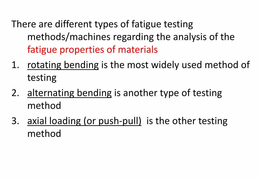
There are different types of fatigue testing methods/machines regarding the analysis of the fatigue properties of materials
1. rotating bending is the most widely used method of testing
2. alternating bending is another type of testing method
3. axial loading (or push-pull) is the other testing method

Rotating bending fatigue tester
In this method of testing, a specimen, subjected to a constant bending moment or a constant bending stress by shaping the specimen accordingly is rotated until fracture.
Two types of Rotating bending fatigue testers are:
o Constant bending moment type (4-Point Bending tester) (fig.a)
o Cantilever type (Constant Bending Stress) (fig.b)

Constant bending (4-Point Bending) fatigue tester

Cantilever type rotating bending fatigue tester o In cantilever type rotating bending fatigue testing machines, the bending
moment varies along the gauge length of the specimen.
o Condition of constant stress along the gauge length is satisfied by ‘tapering ’ the specimen.

Alternating bending type fatigue tester o Other standart method of uniaxial fatigue testing is the alternating bending
type fatigue testing, where the bending load itself alternates but the specimen is stationary.

o The axial loading (push-pull) type fatigue tester is the other machine where specimen is not exposed to bending but to pure axial (tensile or copmressive) loading.
o Specimen is held at two ends and loaded cyclically between two extreme (max. & min.) values.
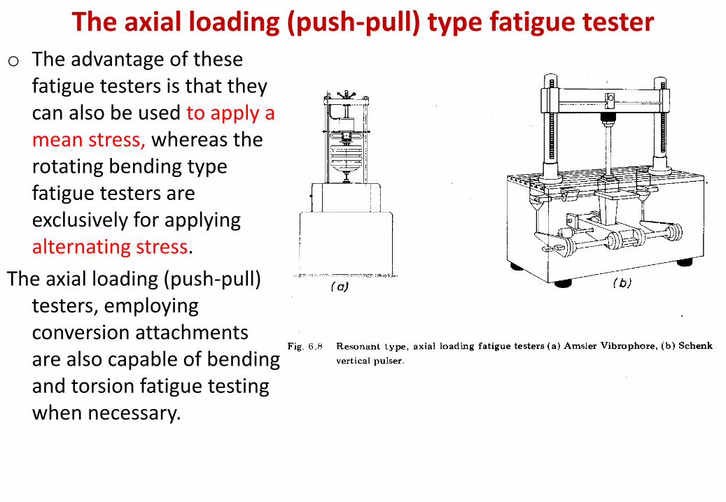
The axial loading (push-pull) type fatigue tester o The advantage of these
fatigue testers is that they can also be used to apply a mean stress, whereas the rotating bending type fatigue testers are exclusively for applying alternating stress.
The axial loading (push-pull) testers, employing conversion attachments are also capable of bending and torsion fatigue testing when necessary.

Standart fatigue test specimens for different fatigue tester machines

FATIGUE TEST • The main aim of the fatigue testing is the determination of some
mechanical properties of the material as in other types of tests like tension, torsion etc .
• Similar to stress-strain curve of tensile test , another curve is constructed for the fatigue test of materials and this curve is called the “S-N” curve.
• On the S-N curve, mechanical properties like fatigue strength, endurance strength, etc. are determined.

• S-N curve of a material is usually constructed by doing multiples of rotating bending fatigue tests of the material.
• Each test is represented by a point on the S-N curve.
In each test,
• A specimen is loaded to create a certain level of stress amplitude (Sa) within the material and then the specimen is rotated until it fractures.
• When the specimen fractures, both the level of stress applied (Sa) and the number of revolutions (cycles, N) to fracture are noted.
• Multiples of tests at different stress levels (from Su down to very low stress values) with corresponding cycles to fracture will create multiples of test points for the construction of S-N curve
S-N curve construction

S-N Curve
o For certain metals and alloys, the S-N curve becomes asymptotic to the horizontal line. This mean that the specimen will not fail for an infinite number of cycles.
o The stress level corresponding to this asymptote is called the, ‘endurance strength’ or ‘the fatigue limit’ of a metal.
o Se is the symbol for endurance strength.
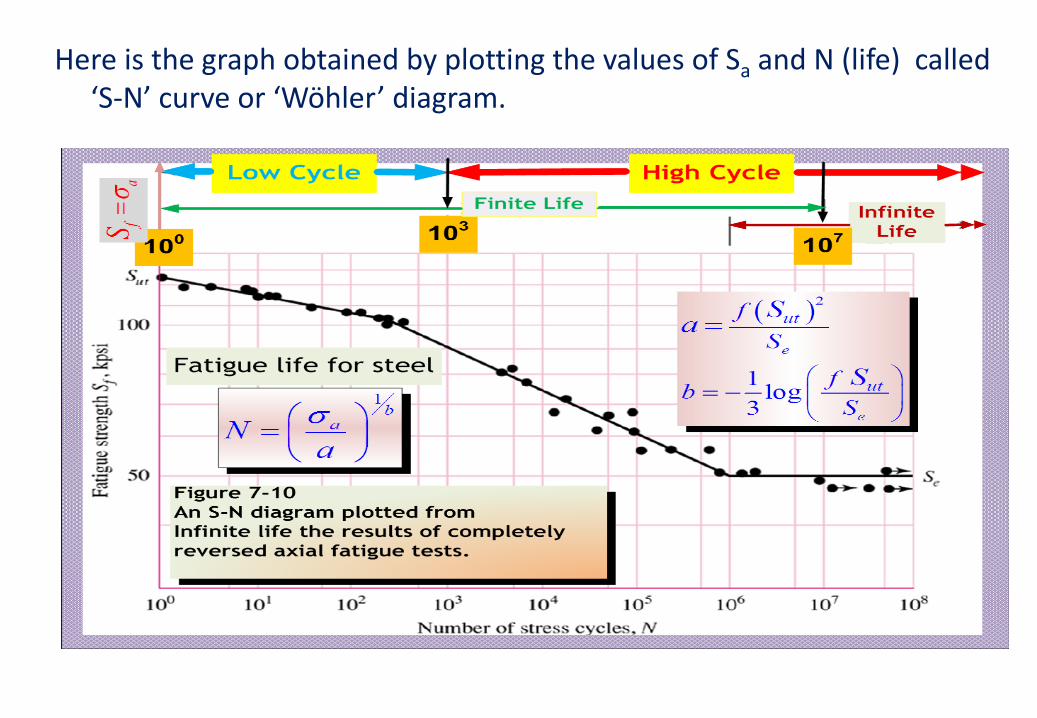
Here is the graph obtained by plotting the values of Sa and N (life) called ‘S-N’ curve or ‘Wöhler’ diagram.

INTERPRETATION OF FATIGUE
• Fatigue is a very complicated phenomenon.
• It is subjected to many variables and is easily influenced by many factors.
• Because, S-N curves are only approximations and represent the fatigue behaviour of laboratory specimens the fatigue life of an actual part may vary considerably from the laboratory results.
The important points about S-N curve are:
o Statical Nature of Fatigue
o Effect of Surface Quality & Treatment
o Size Effects
o Method of Testing

Statical Nature of Fatigue:
- When identical specimens are fatigue tested at same stress level , their fatigue lives are generally not the same , but may vary or scatter a great deal.
- Because of the fact that the fatigue life is easily influenced by many variables, the S-N curve represents a statical average of the test results.
- In other words, the meaning of the S-N curve, as drawn, is that 50% specimens are expected to fail above this curve and the other 50% below it. We can see this differences on P-S-N curve on next page.
- For different probabilities of failure (or for different reliabilities) a modifying factor Mr is used to modify the S-N curve
Mr=1-0.08.P
(see related tables and figures in textbook)
INTERPRETATION OF FATIGUE

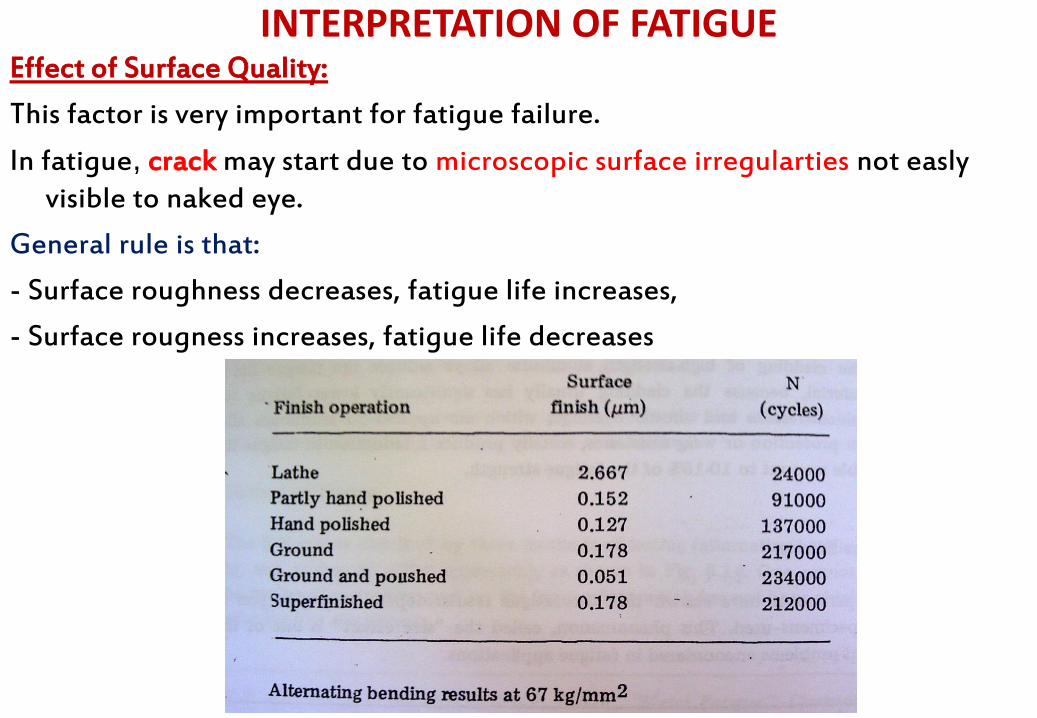
Effect of Surface Quality:
This factor is very important for fatigue failure.
In fatigue, crack may start due to microscopic surface irregularties not easly visible to naked eye.
General rule is that:
- Surface roughness decreases, fatigue life increases,
- Surface rougness increases, fatigue life decreases
INTERPRETATION OF FATIGUE

The modifying factor Ms is used to modify the fatigue strength of parts machined with different methods.
The surface irregularties are effected by cold working the specimen with more plastic flow. This then relaxes the stress concentration produced by surface irregularies.
INTERPRETATION OF FATIGUE

The residual surface compression produced by some mechanical finishes is known to improve the fatigue life because of its retarding effect on crack propogation.
Thus operations like;
o Sandblasting
o Shot peening
o Burnishing & alike generally improve the fatigue life.
On the other hand, the processes like o Electro polishing
o Chem-milling & alike
which do not produce a compressive layer may reduce the fatigue life.
INTERPRETATION OF FATIGUE
Grinding like EDM (electrical discharge machinig) is capable of producing high localized surface temperatures. During a process of severe grinding very high localized surface temperatures are generated.
These hot spots are rapidly quenched by either the bulk of material or cooling fluid thus producing an unintentional ‘heat treated’ layer of non-uniform properties or even cracking.
INTERPRETATION OF FATIGUE

Like machining, surface treatments which produce a high strength layer with favourable compressive residual stresses improve the fatigue properties.
Surface compressive stress may be obtained by;
– Nitriding
– Carburizing
– Flame or induction hardening (if properly done)
– Drastic quenhing of shallow hardening steel

Size Effects
• Fatigue properties (or results) will vary with the size of the material and this has been proven by experiments (as mentioned in tension tests).
• The general observation being that the Fatigue strength of large parts may be considerably lower than that of the small specimens.
• The phenomenon of the size dependency of the test results is called the size effect and it is one of the most important problems encountered in fatigue applications.

• The materials (with larger sizes) become more heterogeneous with increasing size; which makes it all together impossible to prepare specimens which retain the nominal properties of the specified material.
• The usual capacities of the laboratory type testing machines are also limited to conduct experiments with large specimens.
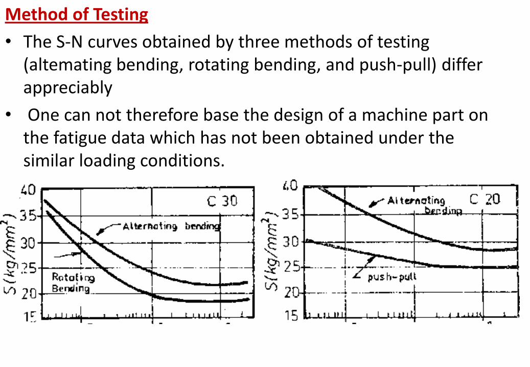
Method of Testing
• The S-N curves obtained by three methods of testing (altemating bending, rotating bending, and push-pull) differ appreciably
• One can not therefore base the design of a machine part on the fatigue data which has not been obtained under the similar loading conditions.

According to accumulated evidence on a specified material;
• The alternating bending test yields the highest S-N
• The rotating bending test produces the next highest S-N
• The push-pull test produces the lowest S-N curve
The push-pull type of test data produces the most conservative design, the next conservative design is based on the rotating bending test data.
Most of the S-N curves are produced by the rotating bending test due to its simplicity.
Make sure that you use correct S-N curve when designing your machine part.
AS A RESULT;
• It can be said that since the fatigue properties of a material is easily influenced by many factors (size, surface, test method and probability).
• The S-N curve obtained from laboratory tests has to be related to real-life design condition by modifiying it with some factors and least the labrotary results should not be used directly with no question.
• Laboratory Endurance strength (Se’) of the materials are therefore corrected for actual conditions by using correction factors like:
Se = ka*kb*kc*kd*ke*kf* Se’

ka = surface (correction) factor kb = size (correction) factor kc = reliability (correction) factor kd= temperature (correction) factor ke = stress concentration (correction) factor kf= miscalleneous (correction) factor Se’= endurance strength of material specimen under lab.
conditions Se= endurance strength of material under actual running
conditions (to be used in design calculations)
Endurance Strength

Endurance limit/Fatigue strength
• The endurance limit, or fatigue strength, of a given material can usually be related to its tensile strength, as shown in the table next.
• The endurance ratio, defined as (endurance limit/ tensile strength), can be used to predict fatigue behavior in the absence of endurance limits results.
• From the table shows, endurance ratio of most ferrous alloys varies between 0.4 and 0.6


CUMULATIVE FATIGUE DAMAGE • In actual case the stress amplitute Sa of the machine parts
which are subjected to fatigue is not constant for whole life and it varies as well.
• It is practically inefficient to design these machine parts in such a manner that all of the stresses induced by the variable external loading are accepted to be below the endurance strength/fatigue limit of the material.
• It is quite possible that machine part may be exposed to different amplitudes of the stress (Sa1, Sa2, Sa3 etc) during its life.
• What then will happen to this part in a certain time? • Will it fracture? • Or will it still have some time/life to carry more stresses?
• When some of these stresses are above the fatigue limit of the material it becomes necessary to consider the fatigue damage accumulated at each step.
• As the fatigue damage added or contributed at each step, cumulative effect of the total damage is refered to as the “camulative fatigue damage”
• There are some different approaches developed to deal with “camulative fatigue damage” concept.
• Not exact, yet the most widely employed damage concept (on acount of its simplicity) is the “Palmgren -Miner” lineer damage rule .


Selection of materials for fatigue resistance:
In many application, the behavior of a component in service is influence by several other factor besides the properties of the material used in its manufacture.
This is particularly true for the cases where the component or structure is subjected to fatigue loading.
The fatigue resistance can be greatly influenced by the service environment, surface condition of the part, method of fabrication and design details.
In some cases, the role of the material in achieving satisfactory fatigue life is secondary to the above parameters, as long as the material is free from major flaws

Steel and cast iron
• Steels are widely used as structural materials for fatigue application as they offer high fatigue strength and good processability at relatively low cost.
• The optimum steel structure for fatigue is tempered martensite, since it provide max homogeneity
• Steel with high hardenability give high strength with relatively mild quenching and hence, low residual stresses, which is desired in fatigue applications.
• Normalized structure, with their finer structure give better fatigue resistance than coarse pearlite structure obtained by annealing.

Nonferrous alloys:
• Unlike ferrous alloy, the nonferrous alloys, with the exception of titanium, do not normally have clear endurance limit.
• Aluminum alloys usually combine corrosion resistance, light weight, and reasonable fatigue resistance
• Fine grained inclusion-free alloys are most suited for fatigue applications.

Plastics • The viscoelasticity of plastics makes their fatigue behavior more
complex than that of metals. • Fatigue behavior of plastics is affected by the type of loading,
small changes in temperature and environment and method of fabrication
• Because of their low thermal conductivity, hysteretic heating can build up in plastics causing them to fail in thermal fatigue or to function at reduces stiffness level.
• The amount of heat generated increases with increasing stress and test frequency. This means that failure of plastics in fatigue may not necessarily mean
fracture

Composite materials:
• The failure modes of reinforced materials in fatigue are complex and can be affected by the fabrication process when difference in shrinkage between fibers and matrix induce internal stresses.
• However from practical experiences, some fiber reinforced plastics are known to perform better in fatigue than some metal
• The advantage of fiber-reinforced plastics is even more apparent when compared on a per weight basis.
• As with static strength, fiber orientation affects the fatigue strength of fiber reinforced composite

• In unidirectional composites, the fatigue strength is significantly lower in directions other than the fiber orientation.
• Reinforcing with continuous unidirectional fibers is more effective than reinforcing with short random fibers.