FATIGUE LIFE DESIGN FOR WIND TURBINE COMPONENTS USING WINLIFE · fatigue life design for wind...
16
FATIGUE LIFE DESIGN FOR WIND TURBINE COMPONENTS USING WINLIFE FATIGUE LIFE DESIGN FOR WIND TURBINE COMPONENTS USING WINLIFE Prof. Dr. Günter Willmerding , Director *1 M.Sc. Jakob Häckh, Vice-Director *1 Dipl.-Ing. Christian Seifert, Sales Manager winLIFE *1 Steinbeis Transfer Centre Traffic Engineering, Germany Dipl.-Ing. Elmar Weber, Calculation Engineer Zollern GmbH & Co KG, Antriebstechnik Herbertingen, Germany M.Sc. Yvan Radovcic, Technical Leader SAMTECH GmbH, Germany THEME Fatigue, Durability KEYWORDS Keywords: fatigue life, winLIFE, wind turbine, gearbox SUMMARY winLIFE is used worldwide for the construction of components with regard to endurance strength. In particular, winLIFE is used in the areas of automobile industry, military, wind energy, ship building and power stations. Nearly all common processes for fatigue life calculation are possible with winLIFE and templates have also been created based on common rules and standards such as those issued by German Lloyd for ship building/wind energy and the FKM guidelines. There are special modules for specific structures (welds, gearwheels & bearings). After a short introduction on the calculation methods implemented in winLIFE, we will show two examples from the wind energy sector of the typical procedure and the results in winLIFE: - Fatigue Life Calculation for a machine casing which is subjected to 7 time-variable sizes taken from measurements. For the fatigue life calculation we take the stress tensor with static superposition of the FE
Transcript of FATIGUE LIFE DESIGN FOR WIND TURBINE COMPONENTS USING WINLIFE · fatigue life design for wind...
FATIGUE LIFE DESIGN FOR WIND TURBINE COMPONENTS USING WINLIFE
FATIGUE LIFE DESIGN FOR WIND TURBINE COMPONENTS USING WINLIFE
Prof. Dr. Günter Willmerding, Director *1 M.Sc. Jakob Häckh, Vice-Director *1
Dipl.-Ing. Christian Seifert, Sales Manager winLIFE *1 Steinbeis Transfer Centre Traffic Engineering, Germany
Dipl.-Ing. Elmar Weber, Calculation Engineer Zollern GmbH & Co KG, Antriebstechnik Herbertingen, Germany
M.Sc. Yvan Radovcic, Technical Leader SAMTECH GmbH, Germany
THEME
Fatigue, Durability
KEYWORDS
Keywords: fatigue life, winLIFE, wind turbine, gearbox
SUMMARY
winLIFE is used worldwide for the construction of components with regard to endurance strength. In particular, winLIFE is used in the areas of automobile industry, military, wind energy, ship building and power stations. Nearly all common processes for fatigue life calculation are possible with winLIFE and templates have also been created based on common rules and standards such as those issued by German Lloyd for ship building/wind energy and the FKM guidelines. There are special modules for specific structures (welds, gearwheels & bearings). After a short introduction on the calculation methods implemented in winLIFE, we will show two examples from the wind energy sector of the typical procedure and the results in winLIFE:
- Fatigue Life Calculation for a machine casing which is subjected to 7 time-variable sizes taken from measurements. For the fatigue life calculation we take the stress tensor with static superposition of the FE
FATIGUE LIFE DESIGN FOR WIND TURBINE COMPONENTS USING WINLIFE
unit load cases scaled with the measured time series. This calculation was carried out by Zollern Co. using ANSYS and winLIFE.
- Calculation of the components of a wind turbine for highly dynamic cases. A wind field is given and the resulting dynamic of the wind turbine is taken into account by exporting the stress tensor time history in winLIFE for the fatigue life calculation. This calculation was carried out using S4WT (Samcef for Wind Turbines) und SAMCEF-Field.
It has been possible to effectively cut the time required for calculations for connecting very large FE and multi-body system structures. It is often necessary to study the variants and for this purpose a project management system has been integrated. It enables batch procedures to be created automatically whereby individual parameters can be systematically varied. Only in this way was it possible to carry out the large number of variant calculations required for a wind turbine certification in an acceptable time.
1: Introduction
Light weight construction is becoming more and more important and the construction is often limited by fatigue life. winLIFE provides the well known and proved methods such as the Nominal Stress Method, Elastic Stress Method and Local Strain Approach in a user friendly interface to save the user having to carry out complex mathematical operations. In some industries technical standards for fatigue life design exist (wind-turbines (GL), ship-construction (GL), and civil engineering (FKM)) and the user has to follow these rules to get a certification. These standards represent the experience of decades and it is recommended to follow these rules. Because of the complexity a software-assistance is desired which winLIFE provides.
The application of Finite Element Analysis is commonly used and in many cases indisputable. As a result winLIFE is designed to be connected to finite element and multi body programs running under Windows versions from XP until Windows 7. To avoid any interface problems, the data transfer is done by data-import and data-export files, which are described in detail. Interfaces for ANSYS, FEMAP and SAMCEF are shipped with winLIFE. winLIFE is an open program, the data structure is documented to enable the user to access it for his own use or to implement additional features. Here a short overview is given and an example for fatigue calculation of wind turbines is included.
FATIGUE LIFE DESIGN FOR WIND TURBINE COMPONENTS USING WINLIFE
2: Overview winLIFE
winLIFE deals with the following capabilities and captures a wide range of fatigue life calculation possibilities:
2.1 Calculation Methods for proportional cases:
If there is no change of the direction of principal stresses (proportional case) the analysis can be performed with high calculation speed. The following procedures are available and in the proportional case only winLIFE BASIC is needed:
- Nominal stress method (HCF=high cycle fatigue and VHCF=very high cycle fatigue)
- Elastic stress method (HCF, VHCF)
- Local Strain Approach (LCF=Low cycle fatigue)
2.2 Calculation Methods for multiaxial cases (Critical Plane Approach)
In complex structures such as automotive bodies or gearbox housings there are often a lot of non proportional loadings acting which lead to a multiaxial problem. For such problems with up to 200 loadings winLIFE MULTIAXIAL has been designed. The critical plane approach is used which leads to time consuming calculations. For each (surface) node of interest in (typically 10…20) planes a fatigue life calculation has to be done. In each plane (of the surface) the normal and shear stresses are calculated and a stress time history is created. For this stress time history a fatigue life calculation is done and a damage D in each plane is ascertained. The plane with the maximum damage is the relevant plane.
2.3 Special Modules
The following special modules are available:
- Seam weldings (Nominal stress, structural stresses, rx concept)
- Gearwheels and Bearings
FATIGUE LIFE DESIGN FOR WIND TURBINE COMPONENTS USING WINLIFE
2.4: Getting Loadings and load spectra
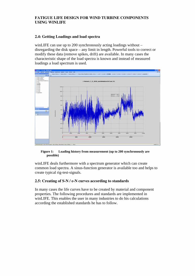
winLIFE can use up to 200 synchronously acting loadings without – disregarding the disk space – any limit in length. Powerful tools to correct or modify these data (remove spikes, drift) are available. In many cases the characteristic shape of the load spectra is known and instead of measured loadings a load spectrum is used.
Figure 1: Loading history from measurement (up to 200 synchronously are possible)
winLIFE deals furthermore with a spectrum generator which can create common load spectra. A sinus-function generator is available too and helps to create typical rig-test-signals.
2.5: Creating of S-N / e-N curves according to standards
In many cases the life curves have to be created by material and component properties. The following procedures and standards are implemented in winLIFE. This enables the user in many industries to do his calculations according the established standards he has to follow.
FATIGUE LIFE DESIGN FOR WIND TURBINE COMPONENTS USING WINLIFE
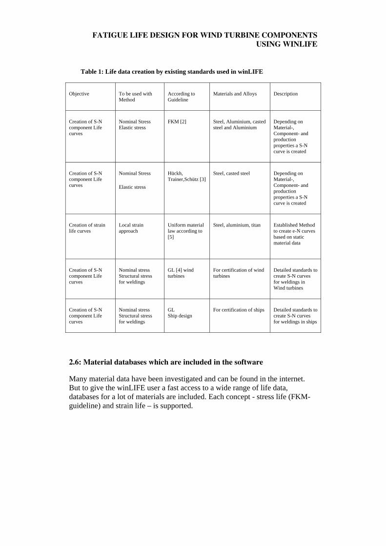
Table 1: Life data creation by existing standards used in winLIFE
Objective To be used with Method
According to Guideline
Materials and Alloys Description
Creation of S-N component Life curves
Nominal Stress Elastic stress
FKM [2]
Steel, Aluminium, casted steel and Aluminium
Depending on Material-, Component- and production properties a S-N curve is created
Creation of S-N component Life curves
Nominal Stress
Elastic stress
Hückh, Trainer,Schütz [3]
Steel, casted steel Depending on Material-, Component- and production properties a S-N curve is created
Creation of strain life curves
Local strain approach
Uniform material law according to [5]
Steel, aluminium, titan Established Method to create e-N curves based on static material data
Creation of S-N component Life curves
Nominal stress Structural stress for weldings
GL [4] wind turbines
For certification of wind turbines
Detailed standards to create S-N curves for weldings in Wind turbines
Creation of S-N component Life curves
Nominal stress Structural stress for weldings
GL Ship design
For certification of ships Detailed standards to create S-N curves for weldings in ships
2.6: Material databases which are included in the software
Many material data have been investigated and can be found in the internet. But to give the winLIFE user a fast access to a wide range of life data, databases for a lot of materials are included. Each concept - stress life (FKM-guideline) and strain life – is supported.
FATIGUE LIFE DESIGN FOR WIND TURBINE COMPONENTS USING WINLIFE
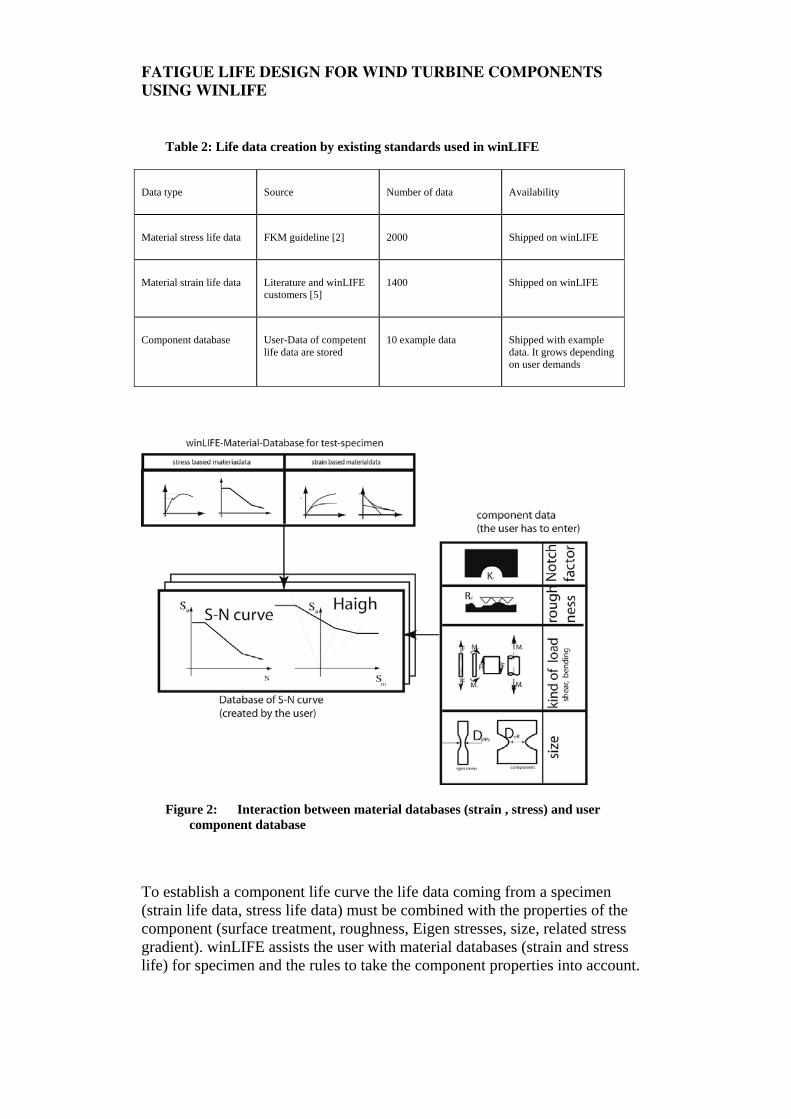
Table 2: Life data creation by existing standards used in winLIFE
Data type Source Number of data Availability
Material stress life data FKM guideline [2] 2000 Shipped on winLIFE
Material strain life data Literature and winLIFE customers [5]
1400 Shipped on winLIFE
Component database User-Data of competent life data are stored
10 example data Shipped with example data. It grows depending on user demands
Figure 2: Interaction between material databases (strain , stress) and user component database
To establish a component life curve the life data coming from a specimen (strain life data, stress life data) must be combined with the properties of the component (surface treatment, roughness, Eigen stresses, size, related stress gradient). winLIFE assists the user with material databases (strain and stress life) for specimen and the rules to take the component properties into account.
FATIGUE LIFE DESIGN FOR WIND TURBINE COMPONENTS USING WINLIFE
The result is a component life curve which is stored in the winLIFE user-database (see figure).
2.7: Statistical Analysis
Based on some statistic parameters – scatter ratio - the user can transform a fatigue life curve to another failure probability he needs.
2.8: Investigating the Importance of loads
winLIFE is used to solve very complex problems with often dozens of loading histories. Beside of fatigue life estimation there is often the intention to simplify the problem for rig testing. For this it is helpful to know which loading is important for fatigue and which not.
winLIFE automatically creates a Load Importance Analysis (LIA). This is easily done in the following way. In a first step a fatigue calculation for each single loading is done, the other loadings are set to zero.
In the next step only one loading is set to zero while the rest of the loadings act unchanged. The damage results of these calculations help to find out the most damage relevant loadings.
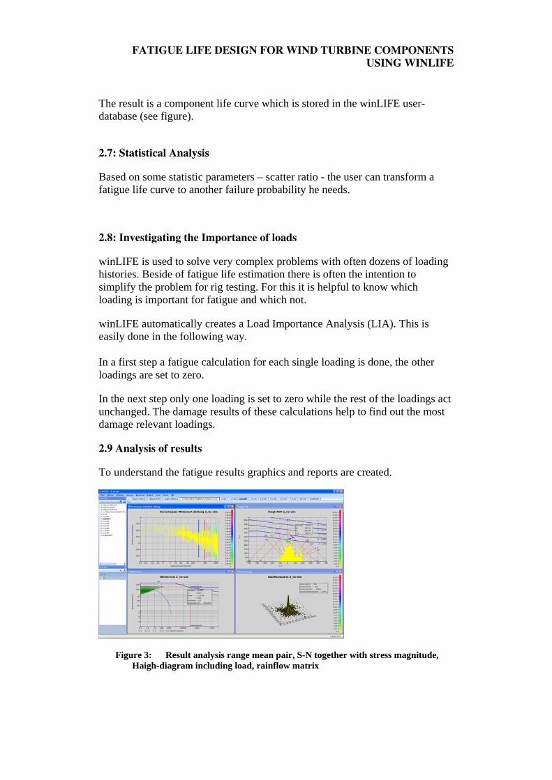
2.9 Analysis of results
To understand the fatigue results graphics and reports are created.
Figure 3: Result analysis range mean pair, S-N together with stress magnitude, Haigh-diagram including load, rainflow matrix
FATIGUE LIFE DESIGN FOR WIND TURBINE COMPONENTS USING WINLIFE
3: Using Finite Element and Multi Body Systems for fatigue life estimation
3.1 Superimposing and scaling static unit load cases from FEA
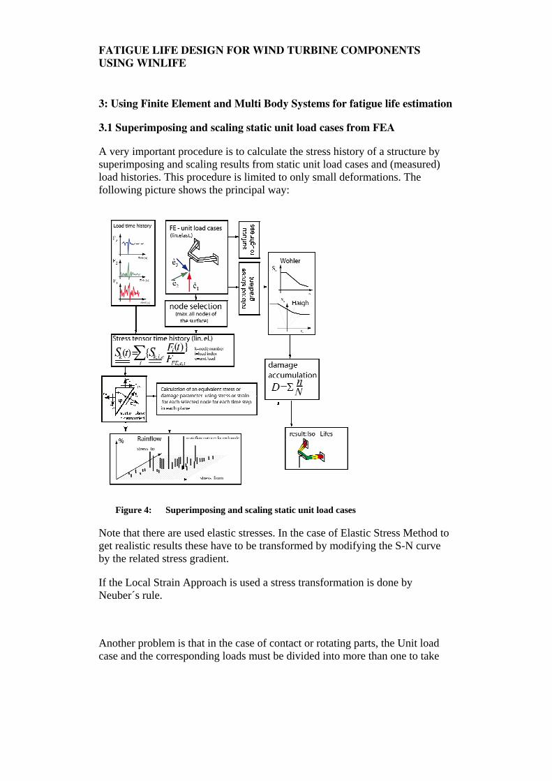
A very important procedure is to calculate the stress history of a structure by superimposing and scaling results from static unit load cases and (measured) load histories. This procedure is limited to only small deformations. The following picture shows the principal way:
Figure 4: Superimposing and scaling static unit load cases
Note that there are used elastic stresses. In the case of Elastic Stress Method to get realistic results these have to be transformed by modifying the S-N curve by the related stress gradient.
If the Local Strain Approach is used a stress transformation is done by Neuber´s rule.
Another problem is that in the case of contact or rotating parts, the Unit load case and the corresponding loads must be divided into more than one to take
FATIGUE LIFE DESIGN FOR WIND TURBINE COMPONENTS USING WINLIFE
the contact or rotating into account. A detailed description of how to do this is described for wind turbines [7].
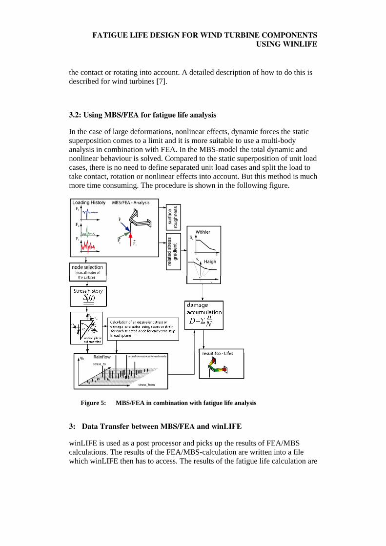
3.2: Using MBS/FEA for fatigue life analysis
In the case of large deformations, nonlinear effects, dynamic forces the static superposition comes to a limit and it is more suitable to use a multi-body analysis in combination with FEA. In the MBS-model the total dynamic and nonlinear behaviour is solved. Compared to the static superposition of unit load cases, there is no need to define separated unit load cases and split the load to take contact, rotation or nonlinear effects into account. But this method is much more time consuming. The procedure is shown in the following figure.
Figure 5: MBS/FEA in combination with fatigue life analysis
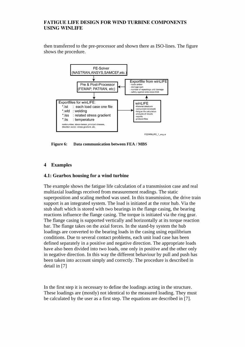
3: Data Transfer between MBS/FEA and winLIFE
winLIFE is used as a post processor and picks up the results of FEA/MBS calculations. The results of the FEA/MBS-calculation are written into a file which winLIFE then has to access. The results of the fatigue life calculation are
FATIGUE LIFE DESIGN FOR WIND TURBINE COMPONENTS USING WINLIFE
then transferred to the pre-processor and shown there as ISO-lines. The figure shows the procedure.
Figure 6: Data communication between FEA / MBS
4 Examples
4.1: Gearbox housing for a wind turbine
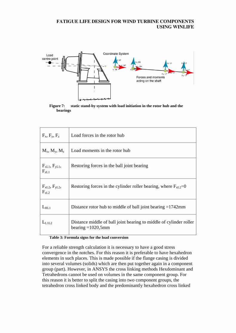
The example shows the fatigue life calculation of a transmission case and real multiaxial loadings received from measurement readings. The static superposition and scaling method was used. In this transmission, the drive train support is an integrated system. The load is initiated at the rotor hub. Via the stub shaft which is stored with two bearings in the flange casing, the bearing reactions influence the flange casing. The torque is initiated via the ring gear. The flange casing is supported vertically and horizontally at its torque reaction bar. The flange takes on the axial forces. In the stand-by system the hub loadings are converted to the bearing loads in the casing using equilibrium conditions. Due to several contact problems, each unit load case has been defined separately in a positive and negative direction. The appropriate loads have also been divided into two loads, one only in positive and the other only in negative direction. In this way the different behaviour by pull and push has been taken into account simply and correctly. The procedure is described in detail in [7]
In the first step it is necessary to define the loadings acting in the structure. These loadings are (mostly) not identical to the measured loading. They must be calculated by the user as a first step. The equations are described in [7].
FATIGUE LIFE DESIGN FOR WIND TURBINE COMPONENTS USING WINLIFE
Figure 7: static stand-by system with load initiation in the rotor hub and the
bearings
Fx, Fy, Fz Load forces in the rotor hub
Mx, My, Mz Load moments in the rotor hub
FxL1, FyL1, FzL1
Restoring forces in the ball joint bearing
FxL2, FyL2, FzL2
Restoring forces in the cylinder roller bearing, where FxL2=0
LRL1 Distance rotor hub to middle of ball joint bearing =1742mm
LL1L2 Distance middle of ball joint bearing to middle of cylinder roller bearing =1020,5mm
Table 3: Formula signs for the load conversion
For a reliable strength calculation it is necessary to have a good stress convergence in the notches. For this reason it is preferable to have hexahedron elements in such places. This is made possible if the flange casing is divided into several volumes (solids) which are then put together again in a component group (part). However, in ANSYS the cross linking methods Hexdominant and Tetrahedrons cannot be used on volumes in the same component group. For this reason it is better to split the casing into two component groups, the tetrahedron cross linked body and the predominantly hexahedron cross linked
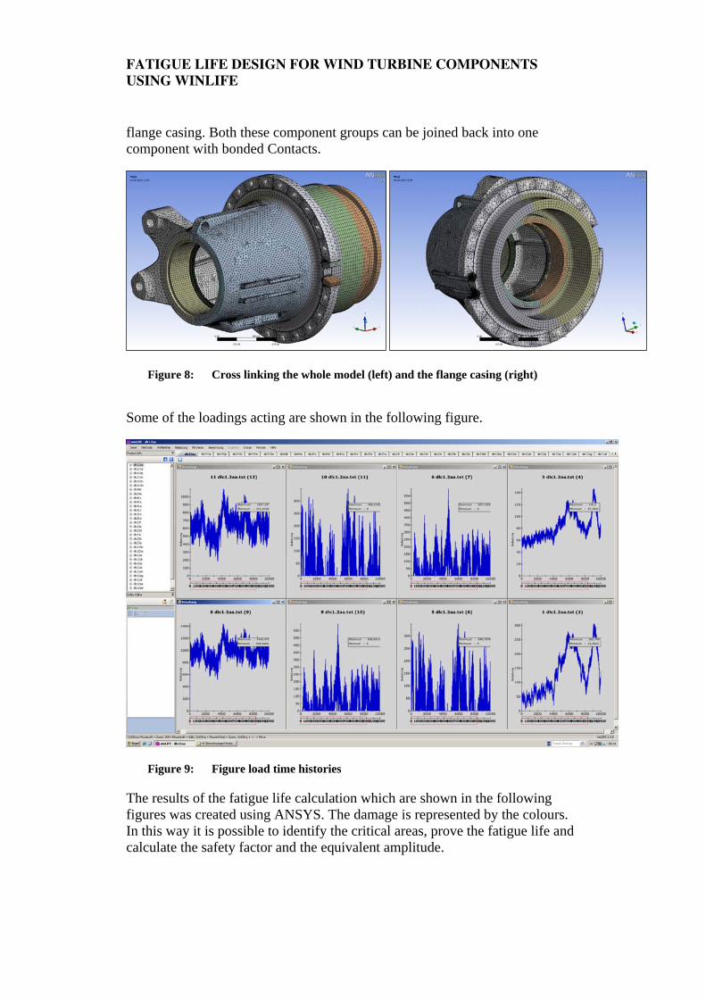
FATIGUE LIFE DESIGN FOR WIND TURBINE COMPONENTS USING WINLIFE
flange casing. Both these component groups can be joined back into one component with bonded Contacts.
Figure 8: Cross linking the whole model (left) and the flange casing (right)
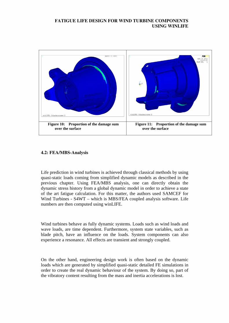
Some of the loadings acting are shown in the following figure.
Figure 9: Figure load time histories
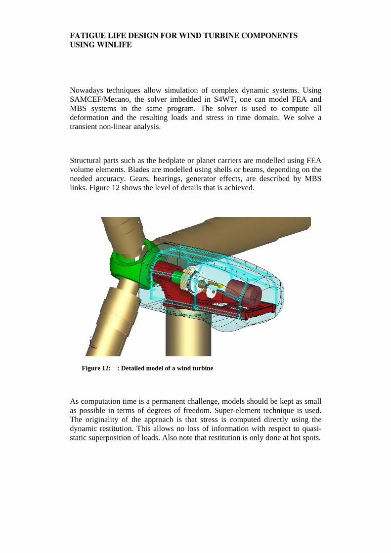
The results of the fatigue life calculation which are shown in the following figures was created using ANSYS. The damage is represented by the colours. In this way it is possible to identify the critical areas, prove the fatigue life and calculate the safety factor and the equivalent amplitude.
FATIGUE LIFE DESIGN FOR WIND TURBINE COMPONENTS USING WINLIFE
Figure 10: Proportion of the damage sum over the surface
Figure 11: Proportion of the damage sum over the surface
4.2: FEA/MBS-Analysis
Life prediction in wind turbines is achieved through classical methods by using quasi-static loads coming from simplified dynamic models as described in the previous chapter. Using FEA/MBS analysis, one can directly obtain the dynamic stress history from a global dynamic model in order to achieve a state of the art fatigue calculation. For this matter, the authors used SAMCEF for Wind Turbines - S4WT – which is MBS/FEA coupled analysis software. Life numbers are then computed using winLIFE.
Wind turbines behave as fully dynamic systems. Loads such as wind loads and wave loads, are time dependent. Furthermore, system state variables, such as blade pitch, have an influence on the loads. System components can also experience a resonance. All effects are transient and strongly coupled.
On the other hand, engineering design work is often based on the dynamic loads which are generated by simplified quasi-static detailed FE simulations in order to create the real dynamic behaviour of the system. By doing so, part of the vibratory content resulting from the mass and inertia accelerations is lost.
FATIGUE LIFE DESIGN FOR WIND TURBINE COMPONENTS USING WINLIFE
Nowadays techniques allow simulation of complex dynamic systems. Using SAMCEF/Mecano, the solver imbedded in S4WT, one can model FEA and MBS systems in the same program. The solver is used to compute all deformation and the resulting loads and stress in time domain. We solve a transient non-linear analysis.
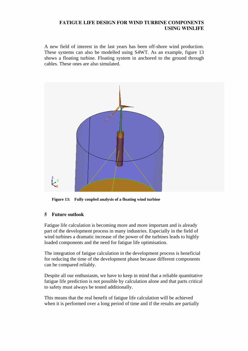
Structural parts such as the bedplate or planet carriers are modelled using FEA volume elements. Blades are modelled using shells or beams, depending on the needed accuracy. Gears, bearings, generator effects, are described by MBS links. Figure 12 shows the level of details that is achieved.
Figure 12: : Detailed model of a wind turbine
As computation time is a permanent challenge, models should be kept as small as possible in terms of degrees of freedom. Super-element technique is used. The originality of the approach is that stress is computed directly using the dynamic restitution. This allows no loss of information with respect to quasi-static superposition of loads. Also note that restitution is only done at hot spots.
FATIGUE LIFE DESIGN FOR WIND TURBINE COMPONENTS USING WINLIFE
A new field of interest in the last years has been off-shore wind production. These systems can also be modelled using S4WT. As an example, figure 13 shows a floating turbine. Floating system in anchored to the ground through cables. These ones are also simulated.
Figure 13: Fully coupled analysis of a floating wind turbine
5 Future outlook
Fatigue life calculation is becoming more and more important and is already part of the development process in many industries. Especially in the field of wind turbines a dramatic increase of the power of the turbines leads to highly loaded components and the need for fatigue life optimisation.
The integration of fatigue calculation in the development process is beneficial for reducing the time of the development phase because different components can be compared reliably.
Despite all our enthusiasm, we have to keep in mind that a reliable quantitative fatigue life prediction is not possible by calculation alone and that parts critical to safety must always be tested additionally.
This means that the real benefit of fatigue life calculation will be achieved when it is performed over a long period of time and if the results are partially
FATIGUE LIFE DESIGN FOR WIND TURBINE COMPONENTS USING WINLIFE
compared with test results. By doing this the user will be able to calculate a more reliable fatigue life prediction.
6 References
[1] Haibach, E., Berger, C., Hänel, B., Wirthgen, G., Zenner, H., Seeger, T.: Rechnerischer Festigkeitsnachweis für Maschinenbauteile, Heft Nr. 183-1, 1994, Forschungskuratorium Maschinenbau, Lyonerstr. 18, Frankfurt/M.
[2] FKM Richtlinie: Rechnerischer Festigkeitsnachweis für Maschinenbauteile, 4.
Extended Edition 2002, Forschungskuratorium Maschinenbau, 1998 [3] Gudehus, Zenner: Leitfaden für eine Betriebsfestigkeitsrechnung, Empfehlung zur
Lebensdauerabschätzung von Maschinenbauteilen. 3rd Edition, ISBN 3-514-00445-5, Publisher: Stahleisen, Düsseldorf.
[4] Guideline for the certification of wind turbines, Edition 2005, Germanischer Lloyd, [5] Bäumel A.; Seeger, T.: Materials Data for Cyclic Loading, supplement 1, Elsevier
Science Publishers B.V.1987, ISBN 0-444-88603 6 [6] Hobbacher, A.: Recommendations for fatigue design of welded joints and
components, International Institute of welding, IIW document IIW-1823-07 December 2008
[7] Weber, E.; Häckh, J.: Willmerding, G.: Fatigue Life calculation using winLIFE.
NAFEMS conference Wiesbaden, 2010.