
Slabs strengthened for punching shear with post-installed ...

Journal of Engineering Sciences, Assiut University, Vol. 39 No 2 pp.269 -282 March 2011
269
FATIGUE BEHAVIOR OF RC SLABS STRENGTHENED EXTERNALLY WITH CFRP SHEETS
Ahmed Sabry FARGHALY1 and Tamon UEDA2 1Lecturer, Dept. of Civil Engineering, Faculty of Engineering, Assiut University, Assiut, Egypt, e-mail:[email protected], 2Professor, Div. of Built Environment, Graduate School of Engineering, Hokkaido University, Sapporo, Japan, e-mail: [email protected]
(Received February 19, 2011 Accepted March17, 2011)
In this paper, the strengthening of two-way slabs using CFRP sheets is evaluated experimentally. The reinforcement ratio equal to 1.29% was chosen to serve the purpose of demarcating the punching shear failure mode. Results show that the punching capacity of two-way slabs can increase to 40% over that of the reference specimen. However, since bridge deck slabs directly sustain repeated moving wheel loads, they are one of the most bridge elements susceptible to fatigue failure. Therefore, this research is designed to investigate the fatigue behavior and fatigue life of concrete bridge deck slabs strengthened externally with CFRP sheets. A total of five slabs were constructed and tested under concentrated monotonic and cyclic loading until failure. Results are presented in terms of deflections, and strains in steel and CFRP at different levels of cyclic loading. The results showed the longer fatigue life of concrete bridge deck slabs strengthened CFRP sheets.
KEYWORDS: continuous fibers; fatigue loading; punching shear; slab.
INTRODUCTION
Deterioration of constructed bridges is a critical issue over the world [1-3]. Typical factors influencing bridge deterioration include ageing, daily traffic, environmental effects such as precipitation, and the use of deicing salts [4,5]. The effect of heavy trucks running on highways is particularly critical on structural deficiency of existing bridges and they result in fatigue damage of deck slabs [6-8]. Carbon fiber reinforced polymer (CFRP) composites for strengthening deteriorated bridge members provide a number of advantages such as a favorable strength-to-weight ratio, strong resistance to environmental and fatigue damage, non-corrosive characteristic, and reduced long-term maintenance expenses [9,10]. The application of CFRP composites has been recently accepted for strengthening existing bridges [1,11,12].
The behavior of structural members, such as reinforced concrete slabs, rehabilitated with CFRP has been experimentally studied and documented by a few number of researchers. However, the fatigue behavior of such strengthened slabs is not widely studied and found the necessity to be investigated. The lack of experimental data on the fatigue of RC slabs strengthened with externally bonded CFRP, stress the need to investigate this subject. In this study, the fatigue performance of CFRP strengthened RC slabs is experimentally investigated. The experimental part of the study is presented in this paper.

Ahmed Sabry FARGHALY and Tamon UEDA
270
EXPERIMENTAL SETUP
Fig. 1 Details of specimens
The present research concerns the investigation of seven reinforced concrete two-way slabs. The specimens consisting of a 1600 mm x 1600 mm x 120 mm square slab with 100 mm x 100 mm central loading point. The slabs were simply supported over the four edges, thus permitting the corner to lift up when load was applied. Typical dimensions and relevant reinforcement details are shown in Fig. 1.
Three slabs were tested under monotonic loading [13]; two of them were
strengthened externally with CFRP sheets with two different widths; 50 mm width
named SF5 and 100 mm width named SF10. The third one is kept un-strengthened as control (SC). The other four slabs were tested under cyclic loading; two of them were not strengthened and tested with different cyclic loadings; one was loaded with 70% of
the ultimate static load (SC-70) and the other one was loaded with 80% of the ultimate static load (SC-80). The remaining two slabs were strengthened externally with 100 mm width CFRP sheets and tested with different cycling loadings. One is loaded with 65% of the ultimate static load (SF10-65) and the other one is loaded with 80% of the ultimate static load (SF10-80). Reinforcements were placed along two perpendicular directions with average effective depth to the center of the two layers of 97 mm. The concrete mixture was designed for an average target cylinder compressive strength of 40 MPa at the time of testing. The steel reinforcement bars were Grade 360 deformed bars. The actual yield strength of steel reinforcements was 340 and 356 MPa for 10 and 13 mm diameter, respectively. Two-way slabs with low or medium reinforcement ratios tend to fail in flexure rather than in punching shear. For two-way slabs that have reinforcement ratios of 1.0% and more, the mode of failure tends to be the punching shear type of failure [14]. Based on this observation; specimens with reinforcement
ratio of 1.29% are designed to experience the punching shear failure mode. Unidirectional CFRP sheets were externally bonded to the tension face of the slab in two perpendicular directions, parallel to the internal tension reinforcement. The sheets were applied in one layer and to avoid debonding failure of the CFRP sheets, the sheets were extended along the full dimension of the slab. Fiber thickness was 0.0167 mm, its
19
8Ø10/dir
15Ø13/dir
7 x 200 100 100
1400
SF5 SF10
Low
er r
ft.
Upp
er r
ft.
1600 650 650 100
120
100 100
a – Concrete dimension
b – Reinforcement details c – Reinforcement and FRP configuration

FATIGUE BEHAVIOR OF RC SLABS STRENGTHENED … 271
maximum tensile strength was 4212 MPa, and the modulus of elasticity was 253 GPa. Test parameters, and details of each specimen are provided in Table 1.
The tests were carried out using a 500 kN capacity hydraulic actuator for monotonic loading and 300 kN capacity hydraulic actuator for fatigue cycling loading. Both systems controlled by a personal computer. The actuator was operated under load control for the cyclic loading and under displacement control for the static tests. The program used for the fatigue testing was similar for all specimens. The load was applied as a sinusoidal function at a frequency of 2 Hz. A minimum load of 5% of ultimate static load was always applied to ensure that movement of the slabs from the setup would not occur. Maximum and minimum values were recorded automatically for each cycle using ADrec recording system (Fig. 2) which allows continuous recording of the load, deflection and strains for each cycle during the whole test. This system has the privilege of not stopping or slowing the frequency to collect the data. The load was applied at the center of the slabs. The deflection at center of slab was measured using a laser transducer to maintain the accuracy of the obtained deflection reading.
Table 1 Experimented specimens
Slab Testing
frequency
Ultimate applied
load (kN)
Max applied
load (kN)
Min applied
load (kN)
Pmax/Pult
Number of cycles to failure,
N SC Monotonic 189.7 n/a n/a n/a n/a SF5 Monotonic 215.3 n/a n/a n/a n/a SF10 Monotonic 260.6 n/a n/a n/a n/a SC-70 2 Hz a 132.8 9.50 0.70 23,400 SC-80 2 Hz a 151.8 9.50 0.80 3,800 SF10-65 2 Hz b 169.4 13.03 0.65 1,950,000 SF10-80 2 Hz b 208.5 13.03 0.80 42,300
aAssumed to be same as SC bAssumed to be same as SF10 n/a = not available
Fig. 2 Adrec recording system
Ahmed Sabry FARGHALY and Tamon UEDA
272
TEST RESULTS AND DISCUSSION
Load-Deflection Characteristics
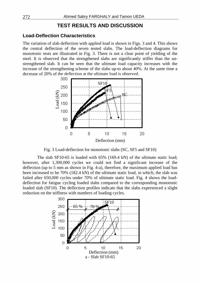
The variation of slab deflection with applied load is shown in Figs. 3 and 4. This shows the central deflection of the seven tested slabs. The load-deflection diagrams for monotonic tests are illustrated in Fig. 3. There is not a clear point of yielding of the steel. It is observed that the strengthened slabs are significantly stiffer than the un-strengthened slab. It can be seen that the ultimate load capacity increases with the increase of the strengthening scheme of the slabs up-to about 40%. At the same time a decrease of 20% of the deflection at the ultimate load is observed.
Fig. 3 Load-deflection for monotonic slabs (SC, SF5 and SF10)
The slab SF10-65 is loaded with 65% (169.4 kN) of the ultimate static load; however, after 1,300,000 cycles we could not find a significant increase of the deflection (up to 5 mm as shown in Fig. 4-a), therefore, the maximum applied load has been increased to be 70% (182.4 kN) of the ultimate static load, in which, the slab was failed after 650,000 cycles under 70% of ultimate static load. Fig. 4 shows the load-deflection for fatigue cycling loaded slabs compared to the corresponding monotonic loaded slab (SF10). The deflection profiles indicate that the slabs experienced a slight reduction on the stiffness with numbers of loading cycles.
a - Slab SF10-65
Load
(kN
)
Deflection (mm)
SC SF5
SF10
Load
(kN
)
Deflection (mm)
SF10 65 % 70 %

FATIGUE BEHAVIOR OF RC SLABS STRENGTHENED … 273
b - Slab SF10-80
Fig. 4 Load-deflection for fatigue cycling slabs
Although the change in stiffness was minor, the permanent deformations and maximum deflection seem to increase with increasing number of cycles. This can be attributed mainly to the cycling creep of concrete, which is known to lead to an increase of permanent deformations [15]. To some extent, laminates based on carbon fibers tested under fatigue bending conditions exhibited a constant increase of deflections due to the micro cracking of the matrix [16].
Fig. 5 Deflections versus normalized number of cycles
The changes in deformations are typically used as a means to quantify the damage accumulation due to the increasing number of cycles. Deflections and stiffness can help characterize the fatigue damage. In Fig. 5 the deflections versus normalized number of cycles for the tested slabs that failed during the fatigue testing are illustrated. For slab SF10-65, there was an initial increase of the deflections, continued by a stable region where the deflection remained almost the same, and after 1,300,000
Load
(kN
)
Deflection (mm)
SF10
Def
lect
ion
(mm
)
Normalized No. of Cycles (%)
0
5
10
15
20
0 0.2 0.4 0.6 0.8 1
SF10-65
SF10-70
SF10-80

Ahmed Sabry FARGHALY and Tamon UEDA
274
cycles the applied load has been increased to 70% of the ultimate load (instead of 65%) which coincide with a sudden increase of the deflection followed by a continuous increase of the deflection with respect to the number of cycles until failure. Slab SF10-80 exhibited same behavior as slab SF10-70. In both cases there was a significant increase of deflections before failure, typically 5% before failure. This is a very important observation, since the upcoming failure may be detected by monitoring the deflections.
Fig. 6 Delta deflections versus normalized number of cycles
Fig. 7 Stiffness versus normalized number of cycles
In Fig. 6, Delta deflections versus the number of cycles are presented for the tested slabs under fatigue cyclic loading. “Delta deflection” is defined as the difference in deflection between the minimum and maximum load within a cycle, and can be used as a very good indication of change in stiffness. We can see that the delta deflection has increased slightly with an increasing number of fatigue cycles.
Del
ta D
efle
ctio
n (m
m)
Normalized No. of Cycles (%)
0
2
4
6
0 0.2 0.4 0.6 0.8 1
SF10-65
SF10-70
SF10-80
0
10
20
30
40
50
60
70
0 0.2 0.4 0.6 0.8 1
SF10-65
SF10-70
SF10-80
Stif
fnes
s (k
N/m
m)
Normalized No. of Cycles (%)

FATIGUE BEHAVIOR OF RC SLABS STRENGTHENED … 275
This observation indicates that the stiffness of the strengthened slabs has been decreased under the fatigue loading conditions, as clearly shown in Fig. 7.
Some of the previous studies show that a decrease of the stiffness occurs with an increase of the number of cycles due to local delamination and/or fatigue micro cracking of the composites [16].
Strain Measurement
The measurements included strain in the reinforcing bars at the tension side of the slabs and carbon FRP sheets. The strain in the carbon FRP sheets was measured by strain gauges attached at mid-width of the sheets. Fig. 8 illustrates the position of the attached strain gauges for steel reinforcement (Fig. 8-a) and carbon FRP (Fig. 8-b).
a- Steel reinforcement b- Carbon FRP
Fig. 8 Position of attached stain gauges For all specimens the developed strains of the steel reinforcement at the center
of slabs were shown in Figs. 9 and 10. In all slab results there were no sign of yielding of steel reinforcement signifying the evidence of pure punching failure mode.
Figure 9 shows the strain development of the monotonic tested slabs. It can be seen that, increasing the used amount of CFRP resulted in a decrease of the steel reinforcement strain level fatigue life. Since no delamination occurred before the failure, we can conclude that the role of CFRP was to relieve the stresses of the tension steel reinforcement bars. Obviously, this statement would not be true if the FRP delaminated from the concrete substrate.
Fig. 9 Strain of steel bar at slab center under monotonic loading
uni-axial
bi-axial
Load
(kN
)
Strain (µ)
SF5
SF10
SC

Ahmed Sabry FARGHALY and Tamon UEDA
276
a- SF10-65
b- SF10-80
Fig. 10 Strain of steel bar at slab center under fatigue loading
Under fatigue loading the strain of steel reinforcement is higher than the values obtained from monotonic loading, however, still under the yielding point (as shown in Fig. 10). Increasing the strain level with increasing the number of cycles – although the maximum applied load is less – could be due to the creep effect of the fatigue loading.
Figure 11 shows the strain level at the mid-width of CFRP at the center of slabs tested under monotonic loading. It can be noted that increasing the CFRP width resulted in a reduction in the strain values. It is obvious that the wider the width of the CFRP needs a less strain to carry amount of tension force under the given load.
Load
(kN
)
Strain (µ)
65 % 70 %
SF10
Load
(kN
)
Strain (µ)
SF10

FATIGUE BEHAVIOR OF RC SLABS STRENGTHENED … 277
Fig. 11 Strain of FRP at slab center under monotonic loading
Similar behavior and changes were observed for the maximum measured
strains in CFRP sheets as steel reinforcement bars. Fig. 12 shows comparisons between the maximum measured strains in the CFRP at the center of slabs. As shown in Fig. 12-a, although Slab SF10-65 has completed 1,950,000 cycles (at lower peak load levels) more than Slab SF10-80, the difference in the measured strains in the CFRP of slabs SF 10-65 and SF 10-80 does not exceed 15%. As previously mentioned slab SF 10-65 was loaded under 65% of the ultimate load which result in almost no residual strain in CFRP sheets, but once the load was increased to 70% of the ultimate load, the residual strain in CFRP sheets started to have a significant value as shown in Fig. 12-a. This led to the difference in strain of CFRP between maximum and minimum loads under 1st cycle (65%) is much larger than in the other cycles (70%). For the CFRP, the maximum recorded strain, which was approximately 5300 µ, was still around 30% of the ultimate strain. For steel reinforcement bars, this value was 1,750 µ (approximately 80% of the yield strain of the steel).
a- SF10-65
Load
(kN
)
Strain (µ)
SF5
SF10
Load
(kN
)
Strain (µ)
65 % 70 %
SF10
65 % 70 %

Ahmed Sabry FARGHALY and Tamon UEDA
278
b- SF10-80
Fig. 12 Strain of FRP at slab center under fatigue loading
Failure Mechanism
The experimented slabs showed clear signs of two-way shear failure. Shear failure was evident in the formation of inclined cracks that extended a distance away from the slab center at the tension side of the specimen to the center, followed by punching of the loading area through the slab (as shown in Fig. 13).
Fig. 13 Punching shear failure
In the strengthened slabs, the CFRP sheets at failure load detached transversally near the shear crack as a result of discrete shear deformation on either side of the crack when punching failure occurred. The CFRP sheets have no resistance in the transverse (out-of-plane) direction. Apparently, the corresponding distance or the angle at which the shear cracks propagated away from the loading area was generally the same for the control and the CFRP strengthened specimens and was not influenced by the area of the CFRP sheets used. All specimens failed in a brittle manner, which is the characteristic of punching shear failure. Similar manner was observed for the fatigue-loaded slabs, with changing the maximum applied load or number of cycles, it seems that fatigue loading has no significant effect on the angle of shear cracks propagated.
Load
(kN
)
Strain (µ)
SF10

FATIGUE BEHAVIOR OF RC SLABS STRENGTHENED … 279
a – Slab SC b – Typical strengthened slab
Fig. 14 Crack patterns on the bottom surface
Fig. 15 Typical discontinuity on the top surface of the slabs after failure
The top surface of the failure zone had an elliptical shape around the corners of
the loading plate, while the bottom surface has approximately a circular shape. Figs. 14 and 15 show both the bottom and top faces of tested slabs. The typical discontinuity on the top surface of the slabs after shear failure is exhibited in Fig. 15.
FATIGUE LIFE
The first approach developed to fatigue assessment is represented by stress–fatigue life curves, referred to as Wohler curves or S–N curves (stress S versus number of load cycles N).
There are some fatigue life prediction models available based on tests that were carried out on either scaled, steel-reinforced, concrete bridge deck specimens or full-scale prototypes of steel-free bridge decks [17-19]. These models are empirical equations based on test results using a relatively smaller range of loading cycles and amplitudes. Only Japanese researchers provided a P–N relationship based on rolling wheel tests carried out on full-scale concrete bridge decks reinforced with steel bars as follows [20]:
( ) 52.1loglog.07835.0log +−= NP
P
s
(1)

Ahmed Sabry FARGHALY and Tamon UEDA
280
Comparing the experimental results with the results calculated by Matsui’s equation that can predict the fatigue life with a reasonable accuracy for a static failure (number of cycles, N=1), Eq. (1) yields a value of Pmax/Pult=1.52. It should be mentioned that Matsui et al. [20] set a limitation for the use of Eq. (1) to be valid only for values of N greater than 10,000 cycles.
Fig. 16 Matsui et al. equation and experimental results
The addition of the CFRP sheets system resulted in an increase of the fatigue life. In order to verify the performance of the strengthening system one can examine Fig. 16 where the applied load range versus number of cycles is presented. The fatigue life of strengthened slabs is more than 10 times higher than the fatigue life of non-strengthened slabs in case of 80% maximum applied load. And as the maximum applied load decreased the fatigue life is increasing to 80 times as in the case of 70% maximum applied load. Strengthening the slabs with the CFRP sheets is expected to prolonging their fatigue life and the fatigue life is increasing when the maximum fatigue load has a lower percentage of the ultimate load.
CONCLUSIONS
Conclusions are based on an experimental study conducted on seven reinforced concrete slabs. Three slabs, two of them strengthened with CFRP sheets and one kept as control specimen, were initially tested under static loading in order to clarify their ultimate load carrying capacity. The other four were tested under cyclic loading. Two of them were strengthened with the same CFRP sheet scheme and loaded with different ratio of static ultimate load as the maximum load, and the other two were not strengthened and loaded with different ratio of static ultimate load. The following conclusions are drawn from this study: 1. Punching shear was the mode of failure for all tested slabs. 2. The use of CFRP increased the stiffness and improved the punching shear capacity
of the strengthened slabs.
0
0.2
0.4
0.6
0.8
1
1.2
1.4
1.6
1.00E+00 1.00E+02 1.00E+04 1.00E+06 1.00E+08
Matsui
Strengthened slabs
Un-Strengthened slabs
No. of Cycles, N
Pm
ax/P
ult
Eq. 1

FATIGUE BEHAVIOR OF RC SLABS STRENGTHENED … 281
3. Depending on the amount of CFRP sheets used, the increase in punching shear resistance varied from 20% to 40% of load-carrying capacity of the control slab.
4. The role of the CFRP sheet is to increase the strength and stiffness of the slab and also to reduce the stress in the steel. Thus, the fatigue life of strengthened slabs is increased compared to the fatigue life of un-strengthened slabs for the same applied load.
5. The equation proposed by Matsui could predict the fatigue life of un-strengthened slabs; however, a modification needs to be conducted to predict the fatigue life for strengthened slabs.
ACKNOWLEDGEMENT
Japan Society for the Promotion of Science (JSPS) provided financial support to this research, to which the authors are grateful.
REFERENCES
[1] Rizkalla, S. and Labossiere, P. “Structural Engineering with FRP- in Canada.” Concrete International, ACI, 21(10), 1999, pp. 25-28.
[2] Kim, Y.J., Tanovic, R., and Wight, R.G. “Recent advances in performance evaluation and flexural response of existing bridges.” J. Perf. Constr. Facil, 23(3), 2009, pp.190-200.
[3] Matsui, S. “Review of researches and technologies on highway bridge decks by using wheel running machines.” JSCE J. Struc. Eng., 55(A), 2009, pp.1408-1419. (in Japanese)
[4] Shahrooz, B.M., Saraf. V., Godbole, B., and Miller, R.A. “Response of Slab Bridges Before, During, and After Repair.” J. Bridge Engrg., ASCE, 7(5), 2002, pp. 267-275.
[5] Kim, Y.J., Green, M.F., and Fallis, G.J. “Repair of bridge girder damaged by impact loads with prestressed CFRP sheets.” J. Bridge. Eng., ASCE, 13(1), 2008, pp. 15-23.
[6] Papavizas, P. and Kostem, C.N. “Structural response of simple span bridges to nonstandard vehicles.” The 2nd Annual International Bridge Conference, Engineers’ Society of Western Pennsylvania, 1980, pp. 184-188.
[7] Japan Road Association (JRA). “Specification for road bridges.” Japan Road Association, Tokyo, Japan (in Japanese), 2002.
[8] Kim, Y.J. and Yoon, D.K. “Identifying critical sources of bridge deterioration in cold regions through the constructed bridges in North Dakota.” J. Bridge Eng., ASCE, 15(5), 2010, pp. 542-542.
[9] Bakis, C.E., Bank, L.C., Brown, V.L., Cosenza, E., Davalos, J.F., Lesko, J.J., Machida, A., Rizkalla, S.H., and Triantafillou, T.C. “Fiber-Reinforced Polymer Composites for Construction-State-of-the-Art Review.” J. Compos. Constr., ASCE, 6(2), 2002, pp. 73-87.
[10] Teng, J.G, Chen, J.F., Smith, S.T., and Lam, L. “Behavior and strength of FRP strengthened RC structures: a state-of-the-art review.” Structures and Buildings, ICE, 156(1), 2003, pp. 51-62.

Ahmed Sabry FARGHALY and Tamon UEDA
282
[11] Stallings, J.M., Tedesco, J.W., El-Mihilmy, M., and McCauley, M. “Field Performance of FRP Bridge Repairs.” J. Bridge Eng., ASCE, 5(2), 2000, pp. 107-113.
[12] Kim, Y.J., Green, M.F., and Wight, R.G. “Live load distributions on an impact damaged prestressed concrete girder bridge strengthened with prestressed CFRP sheets.” J. Bridge. Eng., ASCE, 13(2), 2008, pp. 202-210.
[13] Farghaly, A.S., Ueda, T. “Prediction of Punching Shear Strength of Two-Way Slabs Strengthened Externally with FRP Sheets.” J. Compos. Constr., ASCE, 15(2), 2011, (in press).
[14] Marzouk, H., and Hussein, A. “Experimental Investigation on the Behavior of High-Strength Concrete Slabs.” ACI Struct. J., 88(6), 1991, pp. 701-713.
[15] Papakonstantinou, C. G., Petrou, M. F., and Harries, K. A. “Fatigue Behavior of RC Beams Strengthened with GFRP Sheets.” J. Compos. Constr., ASCE 5(4), 2001, pp. 246-253.
[16] Papakonstantinou, C. G., and Balaguru, P. N. “Fatigue Behavior of High Temperature Inorganic.” J. Mat. Civ. Engrg., ASCE, 19(4), 2007, pp. 321-328.
[17] Sonoda, K., and Horikawa, T. “Fatigue strength of reinforced concrete slabs under moving loads.” Proc., IABSE Colloquium on Fatigue of Steel and Concrete Structures, International Association for Bridge and Structural Engineering, Zurich, Switzerland, 1982, pp. 455–462.
[18] Mufti, A. A., Memon, A. H., Bakht, B., and Banthia, N. “Fatigue investigation of the steel-free bridge deck slab.” ACI Int. SP-206, American Concrete Institute, Farmington Hills, Mich., 2002, pp. 61–70.
[19] Mufti, A. A., Memon, A. H., and Klowak, C. “Study of static and fatigue behavior of second-generation steel-free concrete bridge decks.” Proc., Int. Workshop on Innovative Bridge Deck Technologies, Winnipeg, Man., Canada, 2005, pp. 49–61.
[20] Matsui, S., Tokai, D., Higashiyama, H., and Mizukoshi, M. “Fatigue durability of fiber-reinforced concrete decks under running wheel load.” Proc., 3rd Int. Conf. on Concrete under Severe Conditions, Univ. of British Columbia, Vancouver, Canada, 2001, pp. 982–991.
قواة باستخدام األلياف الكربونيةللبالطات الخرسانية المسلحة الم االجهاد المتكررسلوك
هى العنصر االساسى الذى حيث أنها لالنهيار أكثر العناصرعرضة منتعتبر البالطات الخرسانية في الكباري من االنهيار للبالطات المتكرر و ز اإلجهادتحليل سلوك فى هذا البحثتم لذلك، .الحمال المتكررةيتعرض ل
و دوري أحاديبالطات تحت حمل مركزى سبع تم اختبار حيث .باستخدام االلياف الكربونية الخراسانية المقواهحدوث االنهيار في عليد يأكتلل ٪ 1.29 تساوي تسليح نسبة وقد تم اختيار. لتقييم هذه البالطات حتى االنهيار
البالطات الخراسانية المقواهتحمل أظهرت النتائج أن قدرة لقد . المركز البالطات الخراسانية نتيجة لقوى القص
كما . المرجعية العينة من ٪ عما كانت عليه 40 باستخدام االلياف الكربونية لقوى القص المركزى يمكن أن تزيد ،التحميل الدوري لياف الكربونية عند مستويات مختلفة منواالنفعال في حديد التسليح و األ الترخيم تعرض النتائج
باستخدام االلياف زمن االنهيار للبالطات الخراسانية المقواهفي زيادة أيضًا أن هناك النتائج أظهرتمنها و .الكربونية


![FIRE PROTECTION SYSTEMS FOR REINFORCED CONCRETE …jcorreia/proj_fct2010_CFRPFire/... · 2011. 2. 16. · FRP-strengthened RC beams [16-19], slabs [20-21] and columns [22] (some of](https://static.fdocuments.us/doc/165x107/609aa998db449b31be067e67/fire-protection-systems-for-reinforced-concrete-jcorreiaprojfct2010cfrpfire.jpg)