FASTENER SYSTEMS - PrimeWebcdn.primeweb.fi/ · FASTENER SYSTEMS The company IHF develops, produces...
20
Standard Fasteners FASTENER SYSTEMS
Transcript of FASTENER SYSTEMS - PrimeWebcdn.primeweb.fi/ · FASTENER SYSTEMS The company IHF develops, produces...
Standard Fasteners
F A S T E N E R S Y S T E M S
GmbH · Phone: +49 (0) 291 / 99 62 - 0 · Fax: +49 (0) 291 / 99 62 - 11 · [email protected] · www.ihf-gmbh.com2
Business and Products
JUMBOTECHTM Production Process
F A S T E N E R S Y S T E M S
The company IHF develops, produces and sells high-strength and high quality fastening elements in the form of bolts, nuts and washers.
The product range consists of:- Strength Classes: 8.8, 10.9, 12.9, 13.9- Bolt Diameter: M12 – M64- Corrosion Protection: Dacromet, Deltaton, Galvanized
70,000 tons a year: One of the biggest producers ofbolts in EuropeIHF relies on the capacities and knowledge of its partnerSBE. With more than 70,000 tons a year SBE is one of thebiggest producers of bolts in Europe. The product rangeof IHF reaches from batch productions to various customproductions, like the HV-stretch-bolt for the wind powerindustry.
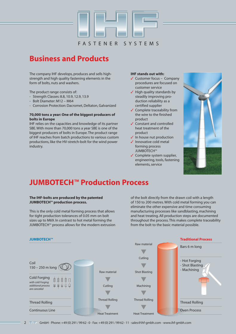
The IHF-bolts are produced by the patentedJUMBOTECHTM production process.
This is the only cold metal forming process that allowsfor tight production tolerances of 0.05 mm on boltsizes up to M69. In contrast to hot metal forming theJUMBOTECHTM process allows for the modern extrusion
of the bolt directly from the drawn coil with a lengthof 150 to 200 metres. With cold metal forming you caneliminate the other expensive and time consumingmanufacturing processes like sandblasting, machiningand heat treating. All production steps are documentedthroughout the process. This makes complete traceabilityfrom the bolt to the basic material possible.
Traditional ProcessJUMBOTECHTM
Bars 6 m long
Coil 150 – 250 m long
Cold Forgingwith cold Forgingadditional processare canceled
Thread Rolling
Continuous Line
Raw material
Cutling
Shot Blasting
Machining
Thread Rolling
Heat Treatment
- Hot Forging- Shot Blasting - Machining
Thread Rolling
Oven Process
▼
▼
▼
▼
▼
Raw material
Cutling
Thread Rolling
Heat Treatment
▼
▼
▼
IHF stands out with:✓ Customer focus – Company
procedures are focused on customer service
✓ High quality standards by steadily improving pro- duction reliability as acertified supplier
✓ Complete traceability from the wire to the finished product
✓ Constant and controlledheat treatment of theproduct
✓ In house nut production ✓ Innovative cold metal
forming processJUMBOTECHTM
✓ Complete system supplier, engineering, tools, fastening elements, service

3GmbH · Phone: +49 (0) 291 / 99 62 - 0 · Fax: +49 (0) 291 / 99 62 - 11 · [email protected] · www.ihf-gmbh.com
Engineering
Material Selection
Manufacturer Qualification
The engineering department provides completetechnical support to meet the customer requirements.This includes detailed assembly conditions, loadmeasurements, and surface condition requirements.
With this support the customer receives a technicalsolution with a commercial bolt connection.
The production of the IHF-fastening elements is licensedand certified according to the following quality systemsISO 9001:200, ISO TS 16949:2002 and UNI EN ISO 14001for the environment management system.
The HV-sets fulfill the requirements of the GermanBuilding Rules List A, Part 1 and have compliancecertificates, issued by an accepted corporation. Eachproduct has a control plan and process run with detailedinstructions for every step of manufacturing. In additionthere are quality control plans with all valid qualityprocesses and instructions.
Documented control results are kept for 15 years.The quality certificates according to DIN 10204, torquecertificates according to DIN 18800-7 and hydrogencertificates can be shown upon customer’s request.
The quality of the products begins with the selection ofcertificated suppliers. The materials used meet the re -quirements according to ISO 898-1 (bolts) and ISO 898-2(nuts) regarding the chemical composition. Only carbonsteel with additives or alloyed steel with suitable degreesof purity are used.
Regarding surface defects the product class D accordingto DIN EN 10221 is used. The surface finish, chemical com-position, microstructure and formability are controlledin the lab. Special material requirements, such as threadforms and surface finishes can be supplied upon thecustomer’s request.
F A S T E N E R S Y S T E M S

GmbH · Phone: +49 (0) 291 / 99 62 - 0 · Fax: +49 (0) 291 / 99 62 - 11 · [email protected] · www.ihf-gmbh.com4
F A S T E N E R S Y S T E M S
The Manufacturing Process
1. Wire rod stock yardIncoming wire coil is checked prior to acceptance on thebasis of IHF’s quality requirements and stored in specificareas to ensure error-free collection.
2. Wire coil heat treatmentComputer controlled spheroid annealing is done in bellfurnaces.
5. Tool makingFundamental for a flexible manufacturing system, the toolmaking department is equipped with the machine toolsneeded to make the dies that are designed and drawn byour own Engineering Services department.
3. Wire rod pickling and phosphatingA completely automated system renders the surface of the wire rod chemically homogeneous ready for theforging operation.
4. Wire drawingThis operation ensures uniform diameter of the wire coil.
6. Tool heat treatmentAn important feature of the tool making process isvacuum heat treatment.

5GmbH · Phone: +49 (0) 291 / 99 62 - 0 · Fax: +49 (0) 291 / 99 62 - 11 · [email protected] · www.ihf-gmbh.com
F A S T E N E R S Y S T E M S
7. Thread rolling and tappingThese recently updated and enlarged departments havefacilities for threading every type of forging produced.
8. Heat treatmentContinuous furnaces of different capacities (kg/h) with a controlled and constantly monitored atmosphere areused to achieve the mechanical strength properties specified for the various fasteners.
11. ForgingIt is at this stage of the process, using multi-station bolt makers and parts formers (cold forming up to 300 pcs/min), thatparts are given their final shape.
9. ToolstockWith an inventory of over 35,000 tooling componentsfor forging equipment, IHF owns and manages an engineering heritage hard to equal.
10. PackagingThis department has been completely refurbished, andis capable of packaging all current production items automatically.
GmbH · Phone: +49 (0) 291 / 99 62 - 0 · Fax: +49 (0) 291 / 99 62 - 11 · [email protected] · www.ihf-gmbh.com6
F A S T E N E R S Y S T E M S
Tightening procedure of preloaded Hv assembliesaccording to DIN 18800 part 7, 11/2008
Table 1 shows the preload and tightening torques forsteel structural assemblies. The preload should beachieved by tightening the nuts. If the tightening is onlypossible by turning the bolt head it is necessary to usean approved and accepted tightening procedure with asuitable lubrication on the bearing face of the head ofthe bolt. The thread does not need further lubricationas this is already provided by the manufacturer throughthe built-in lubrication of the nut.The following procedures are available for applyingpreload, usually by turning the nut:
■ Torque procedure: A torque MA taken from the table 1, column 3, shall be applied to achieve the specified preload FV according to table 1, column 2. This procedure allows a gradual tightening when a joint has many bolts. Furthermoreit is possible to inspect the bolts as well as to apply asecond round of tightening after some days, to assure that the specified preload is achieved in each bolt;
■ Impact procedureNut is turned relative to the bolt by impact rotating through an air driven impact wrench. The wrench shall be set to preload FV, DI according to column 4 of table 1 which is 10 % higher that that for the torque procedure;
■ Rotation angle procedureTo use this procedure all mating parts shall be flat andin a good firm contact with each other. After having achieved a pre-tightening torque MVA, DW according tocolumn 5 of table 1, an additional rotation of the nut shall be applied to achieve the minimum specified preload indicated in table 1, column 2. The angle of nut rotation must be evaluated by an approved procedure on the original assembly. The elongation of the bolt under full preload might be a suitable measure;
■ Combined procedureThis procedure consists of two steps. Firstly a pre-tightening torque MVA, KV according to the table 1, column 6, has to be applied. After that, if the plates lie firmly together without any gap, a further angle of nut rotation according to table 2 shall be applied.
Contact surfaces of the joints in preloaded bearingconnections with normal HV bolts or with HV fit boltsshould be treated as per DIN 18800 part 7. To preventloss of preload it is necessary to tighten up all bolts in afurther round. Retightening of fully preloading HV boltsafter dismantling shall be avoided. The complete boltassembly (bolt, nut and washers) must be replaced bya new one.
Tightening procedure
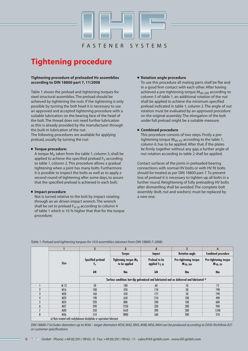
Table 1: Preload and tightening torques for 10.9 assemblies (abstract from DIN 18800-7: 2008)
DIN 18800-7 includes diameters up to M36 – larger diameters M39, M42, M45, M48, M56, M64 can be produced according to DASt-Richtlinie 021or customer specifications
1 M 12 50 100 60 10 752 M16 100 250 110 50 1903 M20 160 450 175 50 1904 M22 190 650 210 100 4905 M24 220 800 240 100 6006 M27 290 1250 320 200 9407 M30 350 1650 390 200 12408 M36 510 2800 560 200 210
a) Nuts treated with molybdenum disulphide or equivalent lubricant
1 2 3 4 5 6
Size
Surface condition: hot-dip galvanized and lubricated and as delivered and lubricated a)
Specified preloadFv
kN
Torque
Tightening torque MAto be applied
Nm
Impact
Preload to beapplied FV, DI
kN
Rotation angle
Pre-tightening torqueMVA, DW
Nm
Combined procedure
Pre-tightening torqueMVA, KV
Nm
7GmbH · Phone: +49 (0) 291 / 99 62 - 0 · Fax: +49 (0) 291 / 99 62 - 11 · [email protected] · www.ihf-gmbh.com
F A S T E N E R S Y S T E M S
Application rules for connections with HV bolt assembly according to DIN 29900 part 1, 11/2008 and DIN 18800 part 7, 11/2008
Preloaded bolted assemblies are very sensitive todifferences in manufacture and lubrication. Therefore,according to EN 14399-1 and DIN 18800-7, SBE bolts shallonly be used together with SBE nuts and SBE washers.
Please note that SBE HV nuts do not need additionallubrication. This could modify the original and approvedtorque-preloaded-relationship.
Independently from the date of production, in case k-class K1 isrequired, SBE bolts, SBE nuts and SBE washers of the samediameter may be combined, but mixing bolts nut washersof different surface treatments is to be avoided.
During the installation, the plain face of the washer withthe marking should show to the joint. The face withthe bevel should be shown to the bolt head or the nut.The nut face with the marking should be visible afterassembly.
In the preloaded connection the installed HV bolts mustshow a minimum one full thread protruding from the nut.
To adjust the bolt length and the thread length with thethickness of the joint, packing up to washers or shimswith 12 mm thickness maximum may be used on theside not turned.
The parallelism of the two outside planes of the jointmust be less or equal to 4 % (ca. 2°) for steel constructionswith no oscillating loads and if the assembly is tightenedby the nut. In constructions under oscillating loads theparallelism must be less or equal to 2 % (ca. 1°), if theskewness is more than the values mentioned then cham-fered washers of sufficient hardness shall be applied.Bolted connections in U-profiles or in I-profiles of oldersize with sloped inside flanges need chamfered washersaccording DIN 6917 or DIN 6918. HV bolts tightenedup to the specified preload need measures to preventloosening of the preload. Short and long slotted holespossibly need enlarged washers or additional shims.They shall not be applied without the agreement of thedesign engineer. They are usually subjected to separatechecks by the constructor.
To calculate the torque, tension and the friction coeffi-cient of the assemblies, two test benches are available inthe Laboratory, with a maximum torque of 18.000 Nmand a clamping load up to 1.800 kN.
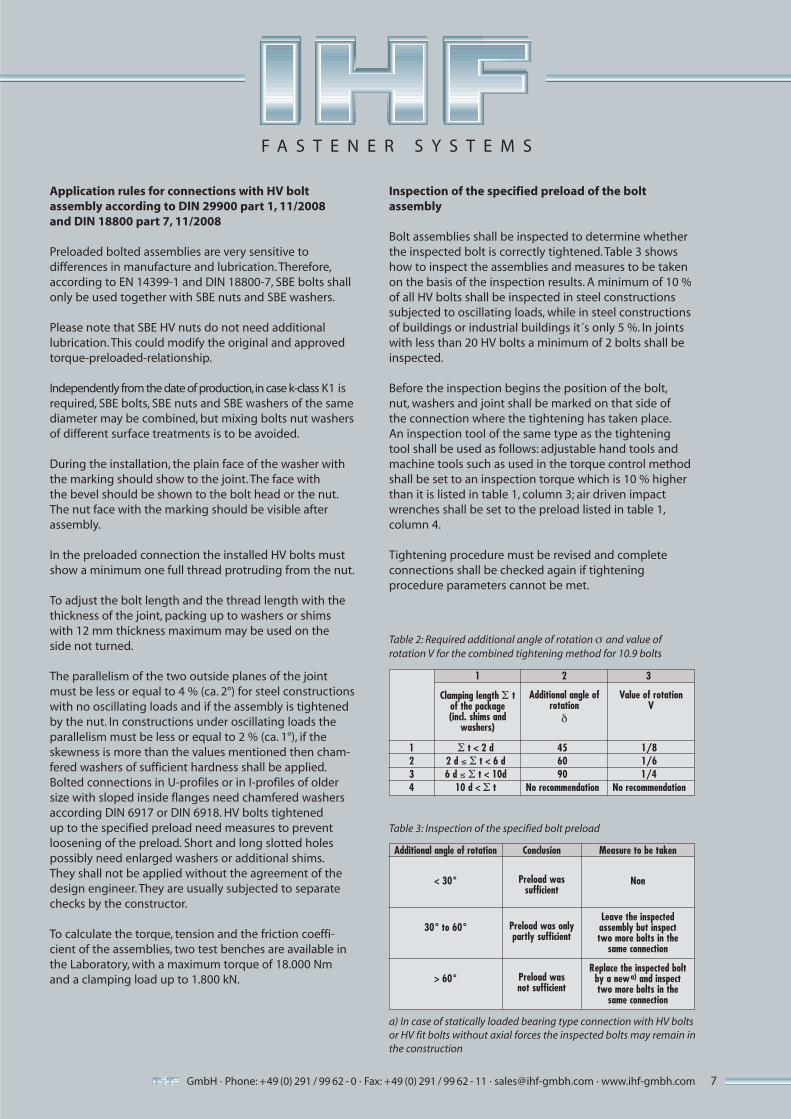
Table 2: Required additional angle of rotation s and value ofrotation V for the combined tightening method for 10.9 bolts
Table 3: Inspection of the specified bolt preload
Additional angle of rotation Conclusion Measure to be taken
a) In case of statically loaded bearing type connection with HV boltsor HV fit bolts without axial forces the inspected bolts may remain inthe construction
Clamping length S tof the package(incl. shims and
washers)
Value of rotationV
1 S t < 2 d 45 1/82 2 d ≤ S t < 6 d 60 1/63 6 d ≤ S t < 10d 90 1/4 4 10 d < S t No recommendation No recommendation
1 2 3
Additional angle ofrotation
d
< 30°
30° to 60°
> 60°
Preload was sufficient
Preload was only partly sufficient
Preload wasnot sufficient
Non
Leave the inspected assembly but inspecttwo more bolts in the
same connection
Replace the inspected boltby a newa) and inspecttwo more bolts in the
same connection
Inspection of the specified preload of the boltassembly
Bolt assemblies shall be inspected to determine whetherthe inspected bolt is correctly tightened. Table 3 showshow to inspect the assemblies and measures to be takenon the basis of the inspection results. A minimum of 10 %of all HV bolts shall be inspected in steel constructionssubjected to oscillating loads, while in steel constructionsof buildings or industrial buildings it´s only 5 %. In jointswith less than 20 HV bolts a minimum of 2 bolts shall beinspected.
Before the inspection begins the position of the bolt,nut, washers and joint shall be marked on that side ofthe connection where the tightening has taken place. An inspection tool of the same type as the tighteningtool shall be used as follows: adjustable hand tools andmachine tools such as used in the torque control methodshall be set to an inspection torque which is 10 % higherthan it is listed in table 1, column 3; air driven impactwrenches shall be set to the preload listed in table 1,column 4.
Tightening procedure must be revised and completeconnections shall be checked again if tighteningprocedure parameters cannot be met.

GmbH · Phone: +49 (0) 291 / 99 62 - 0 · Fax: +49 (0) 291 / 99 62 - 11 · [email protected] · www.ihf-gmbh.com8
Dimensions HV-Strenght hexagon head bolts,EN 14399-4Table 4: Dimensions of high-strength hexagon head bolts with large width across flats for structural steel bolting according to DIN 6914
F A S T E N E R S Y S T E M S

9
Table 4: (Continued)
Figure = standardized range of bolt lengths
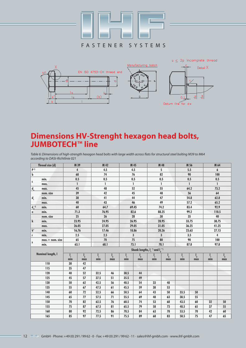
* ls min. = lg max. – 3 P** lg max. = lnominal size – b1) P = pitch of thread (coarse thread)2) For lengths above the continuous step line3) For lengths below the continuous step line4) The maximum value of dw shall not exceed the actual width across flats
Figure = additional range of bolt lengths On customer request different lengths can be produced.
GmbH · Phone: +49 (0) 291 / 99 62 - 0 · Fax: +49 (0) 291 / 99 62 - 11 · [email protected] · www.ihf-gmbh.com
F A S T E N E R S Y S T E M S
GmbH · Phone: +49 (0) 291 / 99 62 - 0 · Fax: +49 (0) 291 / 99 62 - 11 · [email protected] · www.ihf-gmbh.com10
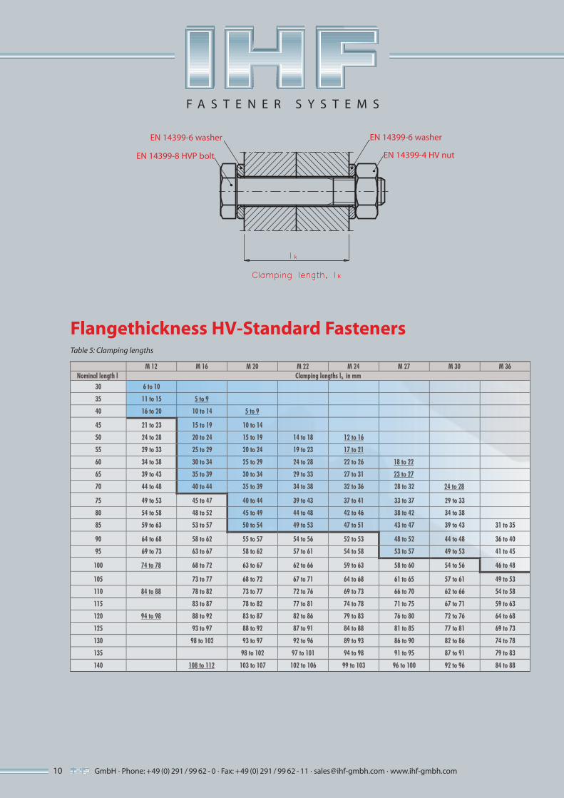
Flangethickness HV-Standard FastenersTable 5: Clamping lengths
F A S T E N E R S Y S T E M S
EN 14399-6 washer
EN 14399-8 HVP bolt
EN 14399-6 washer
EN 14399-4 HV nut

11
M 12 M 16 M 20 M 22 M 24 M 27 M 30 M 36
Nominal length, l Clamping lengths t in mm
145 122 to 127 118 to 123 117 to 122 114 to 119 111 to 116 109 to 114 103 to 108
150 127 to 132 123 to 128 122 to 127 119 to 124 116 to 121 114 to 119 108 to 113
155 132 to 137 128 to 133 127 to 132 124 to 129 121 to 126 119 to 124 113 to 118
160 137 to 142 133 to 138 132 to 137 129 to 134 126 to 131 124 to 129 118 to 123
165 142 to 147 138 to 143 137 to 142 134 to 139 131 to 136 129 to 134 123 to 128
170 147 to 152 143 to 148 142 to 147 139 to 144 136 to 141 134 to 139 128 to 133
175 152 to 157 148 to 153 147 to 152 144 to 149 141 to 146 139 to 144 133 to 138
180 157 to 162 153 to 158 152 to 157 149 to 154 146 to 151 144 to 149 138 to 143
185 162 to 167 158 to 163 157 to 162 154 to 159 151 to 156 149 to 154 143 to 148
190 167 to 172 163 to 168 162 to 167 159 to 164 156 to 161 154 to 159 148 to 153
195 172 to 177 168 to 173 167 to 172 164 to 169 161 to 166 159 to 164 153 to 158
200 177 to 182 173 to 178 172 to 177 169 to 174 166 to 171 164 to 169 158 to 163
210 187 to 192 183 to 188 182 to 187 179 to 184 176 to 181 174 to 179 168 to 173
220 197 to 202 193 to 198 192 to 197 189 to 194 186 to 191 184 to 189 178 to 183
230 203 to 208 202 to 207 199 to 204 196 to 201 194 to 199 188 to 193
240 213 to 218 212 to 217 209 to 214 206 to 211 204 to 209 198 to 203
250 223 to 228 222 to 227 219 to 224 216 to 221 214 to 219 208 to 213
300 264 to 269 258 to 263
350 314 to 319 308 to 313
Figure = standardized range of bolt lengths Figure = additional range of bolt lengths
T Table 5: (Continued)
GmbH · Phone: +49 (0) 291 / 99 62 - 0 · Fax: +49 (0) 291 / 99 62 - 11 · [email protected] · www.ihf-gmbh.com
F A S T E N E R S Y S T E M S
GmbH · Phone: +49 (0) 291 / 99 62 - 0 · Fax: +49 (0) 291 / 99 62 - 11 · [email protected] · www.ihf-gmbh.com12
Thread size (d) M 39 M 42 M 45 M 48 M 56 M 64P 1) 4 4.5 4.5 5 5.5 6b 68 74 76 82 90 100
cmin. 0.5 0.5 0.5 0.5 0.5 0.5max. 1 1 1 1 1 1
da max. 45 48 52 55 64.2 73.2
ds
nom. size 39 42 45 48 56 64min. 38 41 44 47 54.8 62.8max. 40 43 46 49 57.2 65.2
dw2) min. 60 64.7 69.45 74.2 83.4 92.9
e min. 71.3 76.95 82.6 88.25 99.2 110.5
knom. size 25 26 28 30 35 40min. 23.95 24.95 26.95 28.95 33.75 38.75max. 26.05 27.05 29.05 31.05 36.25 41.25
k’ min. 16.76 17.46 18.86 20.26 23.63 27.13r min. 2.5 2.5 3 3 3.5 4
smax.= nom. size 65 70 75 80 90 100min. 63.1 68.1 73.1 78.1 87.8 97.8
Nominal length, lShank lengths, ls
*) and lg**)
ls
minlg
maxls
minlg
maxls
minlg
maxls
minlg
maxls
minlg
maxls
minlg
max110 30 42115 35 47120 40 52 32.5 46 30.5 44125 45 57 37.5 51 35.5 49130 50 62 42.5 56 40.5 54 33 48135 55 67 47.5 61 45.5 59 38 53140 60 72 52.5 66 50.5 64 43 58 33.5 50145 65 77 57.5 71 55.5 69 48 63 38.5 55150 70 82 62.5 76 60.5 74 53 68 43.5 60 32 50155 75 87 67.5 81 65.5 79 58 73 48.5 65 37 55160 80 92 72.5 86 70.5 84 63 78 53.5 70 42 60165 85 97 77.5 91 75.5 89 68 83 58.5 75 47 65
T
Dimensions HV-Strenght hexagon head bolts,JUMBOTECHTM lineTable 6: Dimensions of high-strength hexagon head bolts with large width across flats for structural steel bolting M39 to M64according to DASt-Richtlinie 021
F A S T E N E R S Y S T E M S

13
Thread size (d) M 39 M 42 M 45 M 48 M 56 M 64
Nominal length, lShank lengths, ls
*) and lg**)
ls
minlg
maxls
minlg
maxls
minlg
maxls
minlg
maxls
minlg
maxls
minlg
max170 90 102 82.5 96 80.5 94 73 88 63.5 80 52 70
175 95 107 87.5 101 85.5 99 78 93 68.5 85 57 75
180 100 112 92.5 106 90.5 104 83 98 73.5 90 62 80
185 105 117 97.5 111 95.5 109 88 103 78.5 95 67 85
190 110 122 102.5 116 100.5 114 93 108 83.5 100 72 90
195 115 127 107.5 121 105.5 119 98 113 88.5 105 77 95
200 120 132 112.5 126 110.5 124 103 118 93.5 110 82 100
205 125 137 117.5 131 115.5 129 108 123 98.5 115 87 105
210 130 142 122.5 136 120.5 134 113 128 103.5 120 92 110
215 135 147 127.5 141 125.5 139 118 133 108.5 125 97 115
220 140 152 132.5 146 130.5 144 123 138 113.5 130 102 120
225 145 157 137.5 151 135.5 149 128 143 118.5 135 107 125
230 150 162 142.5 156 140.5 154 133 148 123.5 140 112 130
235 155 167 147.5 161 145.5 159 138 153 128.5 145 117 135
240 160 172 152.5 166 150.5 164 143 158 133.5 150 122 140
245 165 177 157.5 171 155.5 169 148 163 138.5 155 127 145
250 170 182 162.5 176 160.5 174 153 168 143.5 160 132 150
255 175 187 167.5 181 165.5 179 158 173 148.5 165 137 155
260 180 192 172.5 186 170.5 184 163 178 153.5 170 142 160
265 185 197 177.5 191 175.5 189 168 183 158.5 175 147 165
270 190 202 182.5 196 180.5 194 173 188 163.5 180 152 170
275 195 207 187.5 201 185.5 199 178 193 168.5 185 157 175
280 200 212 192.5 206 190.5 204 183 198 173.5 190 162 180
285 205 217 197.5 211 195.5 209 188 203 178.5 195 167 185
290 210 222 202.5 216 200.5 214 193 208 183.5 200 172 190
295 215 227 207.5 221 205.5 219 198 213 188.5 205 177 195
300 220 232 212.5 226 210.5 224 203 218 193.5 210 182 200
305 225 237 217.5 231 215.5 229 208 223 198.5 215 187 205
310 230 242 222.5 236 220.5 234 213 228 203.5 220 192 210
315 235 247 227.5 241 225.5 239 218 233 208.5 225 197 215
320 240 252 232.5 246 230.5 244 223 238 213.5 230 202 220
325 245 257 237.5 251 235.5 249 228 243 218.5 235 207 225
330 250 262 242.5 256 240.5 254 233 248 223.5 240 212 230
335 255 267 247.5 261 245.5 259 238 253 228.5 245 217 235
340 260 272 252.5 266 250.5 264 243 258 233.5 250 222 240
345 265 277 257.5 271 255.5 269 248 263 238.5 255 227 245
350 270 282 262.5 276 260.5 274 253 268 243.5 260 232 250
T Table 6: (Continued)
GmbH · Phone: +49 (0) 291 / 99 62 - 0 · Fax: +49 (0) 291 / 99 62 - 11 · [email protected] · www.ihf-gmbh.com
F A S T E N E R S Y S T E M S
GmbH · Phone: +49 (0) 291 / 99 62 - 0 · Fax: +49 (0) 291 / 99 62 - 11 · [email protected] · www.ihf-gmbh.com14
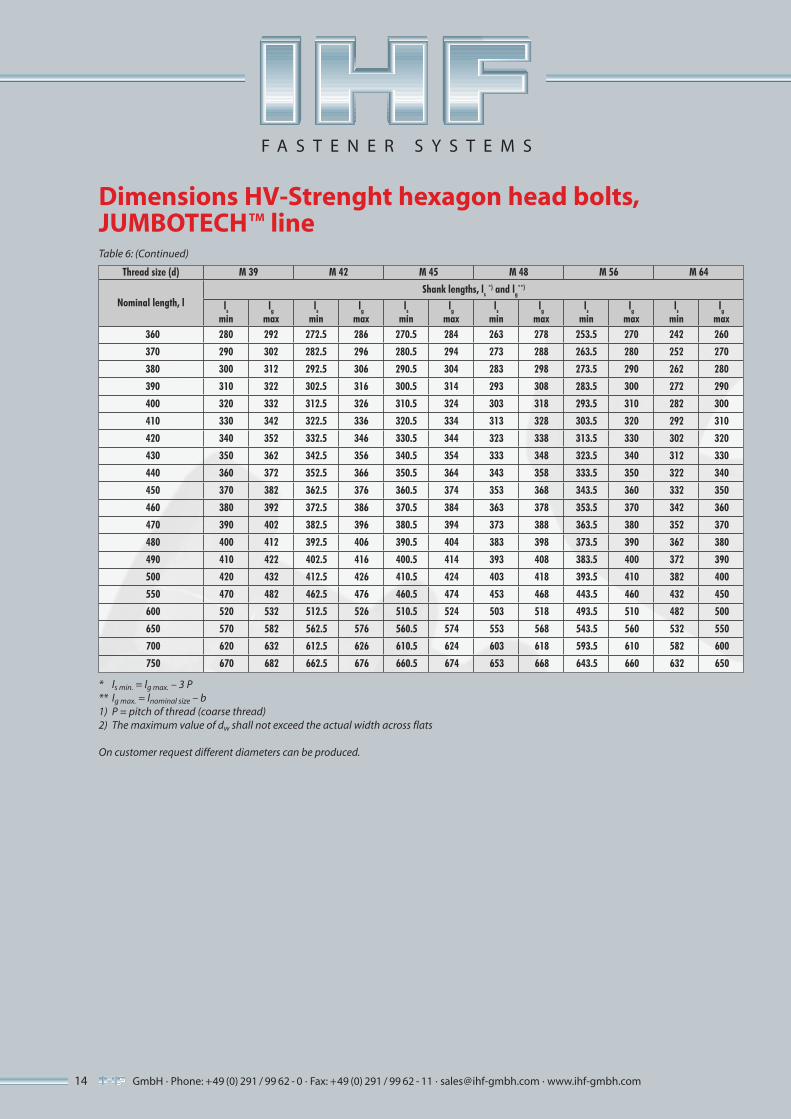
Thread size (d) M 39 M 42 M 45 M 48 M 56 M 64
Nominal length, lShank lengths, ls
*) and lg**)
ls
minlg
maxls
minlg
maxls
minlg
maxls
minlg
maxls
minlg
maxls
minlg
max360 280 292 272.5 286 270.5 284 263 278 253.5 270 242 260
370 290 302 282.5 296 280.5 294 273 288 263.5 280 252 270
380 300 312 292.5 306 290.5 304 283 298 273.5 290 262 280
390 310 322 302.5 316 300.5 314 293 308 283.5 300 272 290
400 320 332 312.5 326 310.5 324 303 318 293.5 310 282 300
410 330 342 322.5 336 320.5 334 313 328 303.5 320 292 310
420 340 352 332.5 346 330.5 344 323 338 313.5 330 302 320
430 350 362 342.5 356 340.5 354 333 348 323.5 340 312 330
440 360 372 352.5 366 350.5 364 343 358 333.5 350 322 340
450 370 382 362.5 376 360.5 374 353 368 343.5 360 332 350
460 380 392 372.5 386 370.5 384 363 378 353.5 370 342 360
470 390 402 382.5 396 380.5 394 373 388 363.5 380 352 370
480 400 412 392.5 406 390.5 404 383 398 373.5 390 362 380
490 410 422 402.5 416 400.5 414 393 408 383.5 400 372 390
500 420 432 412.5 426 410.5 424 403 418 393.5 410 382 400
550 470 482 462.5 476 460.5 474 453 468 443.5 460 432 450
600 520 532 512.5 526 510.5 524 503 518 493.5 510 482 500
650 570 582 562.5 576 560.5 574 553 568 543.5 560 532 550
700 620 632 612.5 626 610.5 624 603 618 593.5 610 582 600
750 670 682 662.5 676 660.5 674 653 668 643.5 660 632 650
*
Dimensions HV-Strenght hexagon head bolts,JUMBOTECHTM lineTable 6: (Continued)
* ls min. = lg max. – 3 P** lg max. = lnominal size – b1) P = pitch of thread (coarse thread)2) The maximum value of dw shall not exceed the actual width across flats
On customer request different diameters can be produced.
F A S T E N E R S Y S T E M S

15
M 39 M 42 M 45 M 48 M 56 M 64
Nominal length l Clamping lengths lk in mm
110 48 to 58
115 53 to 63
120 58 to 68 50 to 61 48 to 58
125 63 to 73 55 to 66 53 to 63
130 68 to 78 60 to 71 58 to 68 54 to 67
135 73 to 83 65 to 76 63 to 73 59 to 72
140 78 to 88 70 to 81 68 to 78 64 to 77 54 to 65.1
145 83 to 93 75 to 86 73 to 83 69 to 82 59 to 70.1
150 88 to 98 80 to 91 78 to 88 74 to 87 64 to 75.1 56 to 69
155 93 to 103 85 to 96 83 to 93 79 to 92 69 to 80.1 61 to 74
160 98 to 108 90 to 101 88 to 98 84 to 97 74 to 85.1 66 to 79
165 103 to 113 95 to 106 93 to 103 89 to 102 79 to 90 71 to 84
170 108 to 118 100 to 111 98 to 108 94 to 107 84 to 95 76 to 89
175 113 to 123 105 to 116 103 to 113 99 to 112 89 to 100 81 to 94
180 118 to 128 110 to 121 108 to 118 104 to 117 94 to 105 86 to 99
185 123 to 133 115 to 126 113 to 123 109 to 121 99 to 110 91 to 103
190 128 to 138 120 to 131 118 to 128 114 to 126 104 to 115 96 to 108
195 133 to 143 125 to 136 123 to 133 119 to 131 109 to 120 101 to 113
200 138 to 148 130 to 141 128 to 138 124 to 136 114 to 125 106 to 118
205 143 to 153 135 to 146 133 to 143 129 to 141 119 to 130 111 to 123
210 148 to 158 140 to 151 138 to 148 134 to 146 124 to 135 116 to 128
215 153 to 163 145 to 156 143 to 153 139 to 151 129 to 140 121 to 133
220 158 to 168 150 to 161 148 to 158 144 to 156 134 to 145 126 to 138
225 163 to 173 155 to 166 153 to 163 149 to 161 139 to 150 131 to 143
230 168 to 178 160 to 171 158 to 168 154 to 166 144 to 155 136 to 148
235 173 to 183 165 to 176 163 to 173 159 to 171 149 to 160 141 to 153
240 178 to 188 170 to 181 168 to 178 164 to 176 154 to 165 146 to 158
245 183 to 193 175 to 186 173 to 183 169 to 181 159 to 170 151 to 163
250 188 to 198 180 to 191 178 to 188 174 to 186 164 to 175 156 to 168
255 193 to 203 185 to 196 183 to 193 179 to 191 169 to 180 161 to 173
260 198 to 208 190 to 201 188 to 198 184 to 196 174 to 185 166 to 178
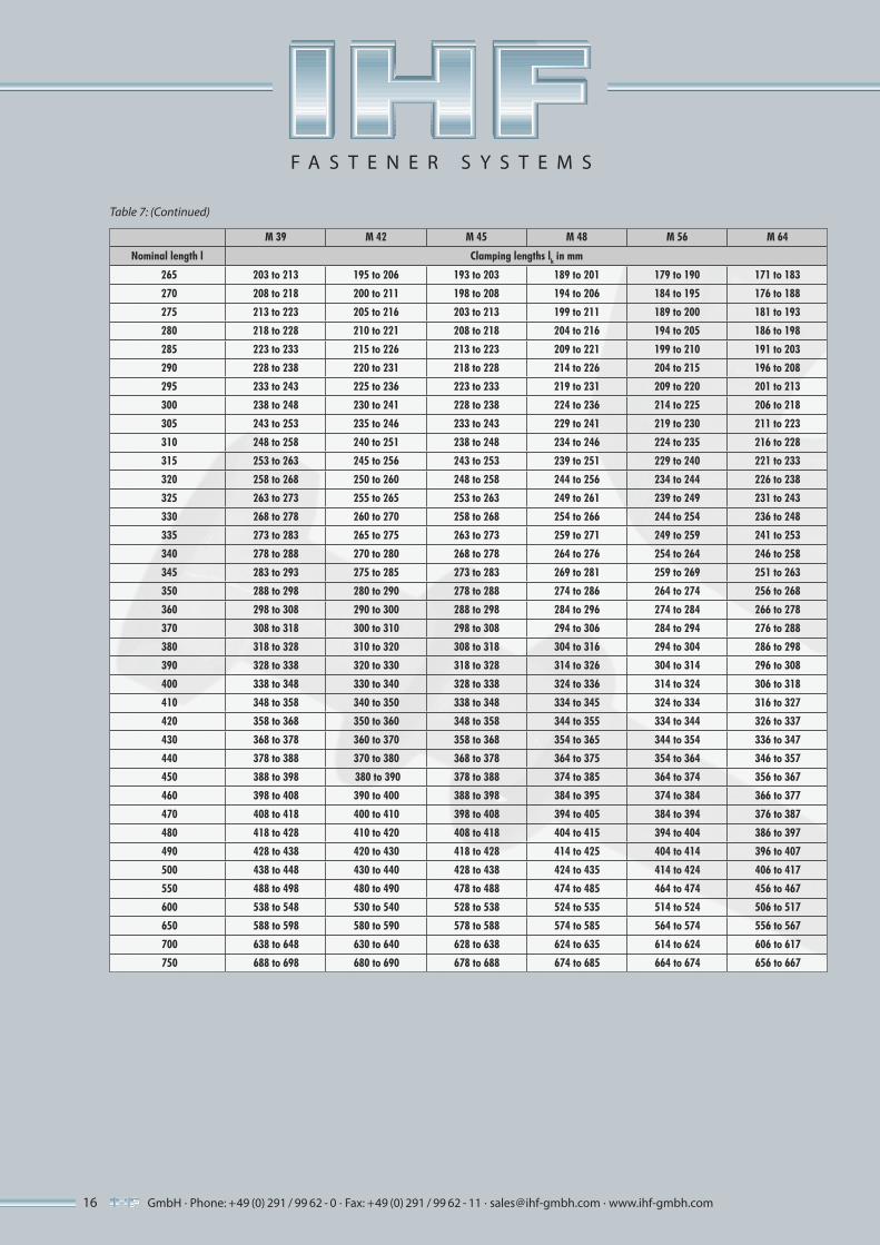
Flangethickness HV-Standard, JUMBOTECHTM lineTable 7: Clamping lengths
GmbH · Phone: +49 (0) 291 / 99 62 - 0 · Fax: +49 (0) 291 / 99 62 - 11 · [email protected] · www.ihf-gmbh.com
F A S T E N E R S Y S T E M S
GmbH · Phone: +49 (0) 291 / 99 62 - 0 · Fax: +49 (0) 291 / 99 62 - 11 · [email protected] · www.ihf-gmbh.com16
M 39 M 42 M 45 M 48 M 56 M 64
Nominal length l Clamping lengths lk in mm
265 203 to 213 195 to 206 193 to 203 189 to 201 179 to 190 171 to 183
270 208 to 218 200 to 211 198 to 208 194 to 206 184 to 195 176 to 188
275 213 to 223 205 to 216 203 to 213 199 to 211 189 to 200 181 to 193
280 218 to 228 210 to 221 208 to 218 204 to 216 194 to 205 186 to 198
285 223 to 233 215 to 226 213 to 223 209 to 221 199 to 210 191 to 203
290 228 to 238 220 to 231 218 to 228 214 to 226 204 to 215 196 to 208
295 233 to 243 225 to 236 223 to 233 219 to 231 209 to 220 201 to 213
300 238 to 248 230 to 241 228 to 238 224 to 236 214 to 225 206 to 218
305 243 to 253 235 to 246 233 to 243 229 to 241 219 to 230 211 to 223
310 248 to 258 240 to 251 238 to 248 234 to 246 224 to 235 216 to 228
315 253 to 263 245 to 256 243 to 253 239 to 251 229 to 240 221 to 233
320 258 to 268 250 to 260 248 to 258 244 to 256 234 to 244 226 to 238
325 263 to 273 255 to 265 253 to 263 249 to 261 239 to 249 231 to 243
330 268 to 278 260 to 270 258 to 268 254 to 266 244 to 254 236 to 248
335 273 to 283 265 to 275 263 to 273 259 to 271 249 to 259 241 to 253
340 278 to 288 270 to 280 268 to 278 264 to 276 254 to 264 246 to 258
345 283 to 293 275 to 285 273 to 283 269 to 281 259 to 269 251 to 263
350 288 to 298 280 to 290 278 to 288 274 to 286 264 to 274 256 to 268
360 298 to 308 290 to 300 288 to 298 284 to 296 274 to 284 266 to 278
370 308 to 318 300 to 310 298 to 308 294 to 306 284 to 294 276 to 288
380 318 to 328 310 to 320 308 to 318 304 to 316 294 to 304 286 to 298
390 328 to 338 320 to 330 318 to 328 314 to 326 304 to 314 296 to 308
400 338 to 348 330 to 340 328 to 338 324 to 336 314 to 324 306 to 318
410 348 to 358 340 to 350 338 to 348 334 to 345 324 to 334 316 to 327
420 358 to 368 350 to 360 348 to 358 344 to 355 334 to 344 326 to 337
430 368 to 378 360 to 370 358 to 368 354 to 365 344 to 354 336 to 347
440 378 to 388 370 to 380 368 to 378 364 to 375 354 to 364 346 to 357
450 388 to 398 380 to 390 378 to 388 374 to 385 364 to 374 356 to 367
460 398 to 408 390 to 400 388 to 398 384 to 395 374 to 384 366 to 377
470 408 to 418 400 to 410 398 to 408 394 to 405 384 to 394 376 to 387
480 418 to 428 410 to 420 408 to 418 404 to 415 394 to 404 386 to 397
490 428 to 438 420 to 430 418 to 428 414 to 425 404 to 414 396 to 407
500 438 to 448 430 to 440 428 to 438 424 to 435 414 to 424 406 to 417
550 488 to 498 480 to 490 478 to 488 474 to 485 464 to 474 456 to 467
600 538 to 548 530 to 540 528 to 538 524 to 535 514 to 524 506 to 517
650 588 to 598 580 to 590 578 to 588 574 to 585 564 to 574 556 to 567
700 638 to 648 630 to 640 628 to 638 624 to 635 614 to 624 606 to 617
750 688 to 698 680 to 690 678 to 688 674 to 685 664 to 674 656 to 667
Table 7: (Continued)
F A S T E N E R S Y S T E M S

GmbH · Phone: +49 (0) 291 / 99 62 - 0 · Fax: +49 (0) 291 / 99 62 - 11 · [email protected] · www.ihf-gmbh.com 17
M12 ÷ M64
Material Steel
General requirements EN 14399-1
Thread
Tolerance 6g
As specified in ISO 261, ISO 965-2
Mechanical properties
Property class 10.9
As specified in ISO 898 Part 1
Tolerances
Product grade C 1)
As specified in ISO 4759 Part 1
Surface finishAs processed (black)
ISO 10684 shall apply with regard to hot dip galvanizing
Acceptance inspection As specified in ISO 3269
1) For M39 to M64 exceptional tolerance for the nominal length (= js 17)
T
Technical delivery conditions EN 14399, JUMBOTECHTM lineTable 7: Technical delivery conditions
F A S T E N E R S Y S T E M S
Size
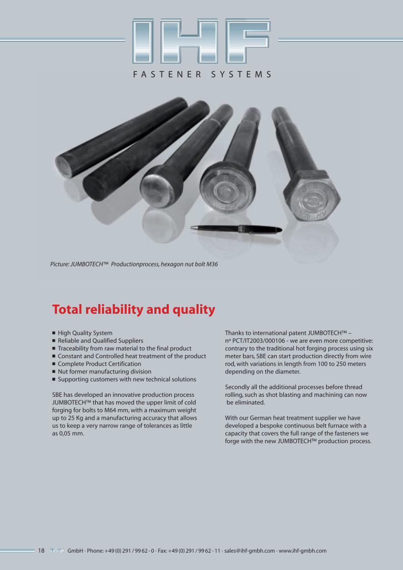
Picture: JUMBOTECH™ Productionprocess, hexagon nut bolt M36
GmbH · Phone: +49 (0) 291 / 99 62 - 0 · Fax: +49 (0) 291 / 99 62 - 11 · [email protected] · www.ihf-gmbh.com18
F A S T E N E R S Y S T E M S
■ High Quality System■ Reliable and Qualified Suppliers■ Traceability from raw material to the final product■ Constant and Controlled heat treatment of the product■ Complete Product Certification■ Nut former manufacturing division■ Supporting customers with new technical solutions
SBE has developed an innovative production processJUMBOTECH™ that has moved the upper limit of coldforging for bolts to M64 mm, with a maximum weightup to 25 Kg and a manufacturing accuracy that allowsus to keep a very narrow range of tolerances as little as 0,05 mm.
Total reliability and quality
Thanks to international patent JUMBOTECH™ –nº PCT/IT2003/000106 - we are even more competitive: contrary to the traditional hot forging process using sixmeter bars, SBE can start production directly from wirerod, with variations in length from 100 to 250 metersdepending on the diameter.
Secondly all the additional processes before thread rolling, such as shot blasting and machining can now be eliminated.
With our German heat treatment supplier we have developed a bespoke continuous belt furnace with a capacity that covers the full range of the fasteners weforge with the new JUMBOTECH™ production process.
19GmbH · Phone: +49 (0) 291 / 99 62 - 0 · Fax: +49 (0) 291 / 99 62 - 11 · [email protected] · www.ihf-gmbh.com
F A S T E N E R S Y S T E M S
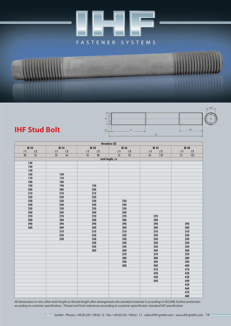
All dimensions in mm, other total length or thread length after arrangement, the standard material is according to ISO 898, Surface protectionaccording to customer specification, Thread and Form tolerances according to customer sprecificatior standard IHF specification
IHF Stud Bolt
threadsize (d)
total length, l o
M 20l 1 l 230 55
l 1 l 2
l o
M 24l 1 l 235 65
M 30l 1 l 245 80
M 36l 1 l 255 95
M 42l 1 l 265 110
M 48l 1 l 275 125
130140150160 160170 170180 180190 190 190200 200 200210 210 210220 220 220230 230 230 230240 240 240 240250 250 250 250260 260 260 260270 270 270 270 270280 280 280 280 280290 290 290 290 290 290300 300 300 300 300 300
310 310 310 310 310320 320 320 320 320330 330 330 330 330
340 340 340 340350 350 350 350360 360 360 360
370 370 370380 380 380390 390 390400 400 400
410 410420 420430 430440 440
450460470480

Applications
HV-Fasteners-Set for wind turbine towers, according to EN 14399-, hot-dip galvanized.
Hot-dip galvanized stud-bolts for blade bearings on wind turbines, with ITH-Round-Nut RMS and ITH-Bolt-TensioningCylinder.
Stud-bolts M36 with hexagon nuts ISO 4032 and spacer for blade bearings on wind turbines,Xylan-Surface Protection.
Worldwide Service Facilities
.. ..
USA . HeadquarterGermany. . Japan. China
. South East Asia
uses the offices of ITH GmbH & Co. KG
INDUSTRIAL HIGHLOAD FASTENERS
IHF GMBH Auf’m Brinke 18 · D-59872 Meschede
Phone: +49 (0) 291 / 99 62 - 0 Fax +49(0)291/996211
EuropeIHF GmbHPhone: +49(0)291/99 62 - 0E-mail: [email protected]
AmericaITH Eng. Company Inc., ChicagoPhone: +(1) (847) 526 -1980E-mail: [email protected]
ChinaITH-GmbH Shanghai Rep. OfficePhone: +86 / 1 / 64 82 35 80E-mail: [email protected]
South East AsiaITH Asia Pacific, Kuala Lumpur, MalaysiaPhone: +60 (3) / 8061 - 6620E-mail: [email protected]
JapanITH Japan Co., Ltd, Funabashi CityPhone: +81 / 47 - 493 - 5221E-mail: [email protected]
Applications
.
F A S T E N E R S Y S T E M S