Fast Response Flywheel Energy Storage Technology …...Fast Response Flywheel Energy Storage...
11
Fast Response Flywheel Energy Storage Technology for Virtual Power Plants and Microgrids Thilo Engelmann, Rainer vor dem Esche, Reddy Tudi Stornetic GmbH, Stetternicher Str. Staatsforst, 52428 Jülich, Germany I. SUMMARY The continued expansion of renewable energy sources like wind power and photovoltaics is gradually reducing short and long-term grid stability, especially as more and more conventional thermal power plants are retired and taken offline. Power to gas, power to heat, battery storage and flexible load management provide a solution to deal with the challenges of long-term (5 to 12 hours) grid stability, while fast response storage technologies such as Flywheel Storage provides an efficient and affordable solution to manage the short-term (0 seconds to 5 minutes) challenges of grid stability. The EFRE project Quirinus [1] and the EDF concept grid [2] are two demonstration projects being tested in Europe, based on a combination of flywheels, gas engines, and renewable generation. They explore the ability to stabilize local grids in critical states, as well as the potential to reduce cost of transition to future grids with carbon free generation and a very high level of power quality and reliability. The intent of this paper is to introduce and present the findings of these demonstration projects. Today conventional synchronous generators, with their ability to provide inertia and adjust to load changes instantaneously, are key for grid stability. When these conventional generators are replaced by renewables, system inertia is reduced, negatively affecting grid stability. A good example is Ireland having a weakly inter-connected <8GW island grid and a renewable penetration growing above 50%. Currently the renewable growth is limited by grid stability constraints requiring the Irish grid operator to invent new market mechanisms and tools to stabilise the grid before the next step to 75% renewable share [3]. Similar problems occur in smaller island or micro-grids partly operating on renewable generation, but still requiring conventional generation for grid stability. The limited size of these grids in combination with load changes makes them sensitive to short-term power quality issues. Typically, customers, particularly power intensive industrials, require a high power quality. With the increasing decentralized solar generation in distribution grids, power quality becomes a challenge and these demonstration projects aim to mitigate these challenges. Fig. 1 shows how fast response Flywheel Storage technology like Stornetic’s DuraStor system can provide reliable and efficient solutions without having the need to operate many synchronous generators to stabilise the grid frequency. This is the basis for the current demonstration projects with EDF and Quirinus. This paper also shows that the investments needed to provide sufficient synthetic inertia can be financed by the savings from not operating synchronous inertia for the sake of grid stabilisation.
Transcript of Fast Response Flywheel Energy Storage Technology …...Fast Response Flywheel Energy Storage...

Fast Response Flywheel Energy Storage
Technology for Virtual Power Plants and
Microgrids Thilo Engelmann, Rainer vor dem Esche, Reddy Tudi
Stornetic GmbH, Stetternicher Str. Staatsforst, 52428 Jülich, Germany
I. SUMMARY
The continued expansion of renewable energy sources like
wind power and photovoltaics is gradually reducing short and
long-term grid stability, especially as more and more
conventional thermal power plants are retired and taken offline.
Power to gas, power to heat, battery storage and flexible load
management provide a solution to deal with the challenges of
long-term (5 to 12 hours) grid stability, while fast response
storage technologies such as Flywheel Storage provides an
efficient and affordable solution to manage the short-term (0
seconds to 5 minutes) challenges of grid stability.
The EFRE project Quirinus [1] and the EDF concept grid
[2] are two demonstration projects being tested in Europe,
based on a combination of flywheels, gas engines, and
renewable generation. They explore the ability to stabilize local
grids in critical states, as well as the potential to reduce cost of
transition to future grids with carbon free generation and a very
high level of power quality and reliability. The intent of this
paper is to introduce and present the findings of these
demonstration projects.
Today conventional synchronous generators, with their
ability to provide inertia and adjust to load changes
instantaneously, are key for grid stability. When these
conventional generators are replaced by renewables, system
inertia is reduced, negatively affecting grid stability. A good
example is Ireland having a weakly inter-connected <8GW
island grid and a renewable penetration growing above 50%.
Currently the renewable growth is limited by grid stability
constraints requiring the Irish grid operator to invent new
market mechanisms and tools to stabilise the grid before the
next step to 75% renewable share [3]. Similar problems occur
in smaller island or micro-grids partly operating on renewable
generation, but still requiring conventional generation for grid
stability. The limited size of these grids in combination with
load changes makes them sensitive to short-term power quality
issues. Typically, customers, particularly power intensive
industrials, require a high power quality. With the increasing
decentralized solar generation in distribution grids, power
quality becomes a challenge and these demonstration projects
aim to mitigate these challenges.
Fig. 1 shows how fast response Flywheel Storage
technology like Stornetic’s DuraStor system can provide
reliable and efficient solutions without having the need to
operate many synchronous generators to stabilise the grid
frequency. This is the basis for the current demonstration
projects with EDF and Quirinus. This paper also shows that the
investments needed to provide sufficient synthetic inertia can
be financed by the savings from not operating synchronous
inertia for the sake of grid stabilisation.

Fig. 1. Comparison of flywheels, batteries and conventional generators during grid fault event.
II. INTRODUCTION/ QUIRINUS-PROJECT
The government of North Rhine-Westfalia initiated the
Quirinus project [1] with funding from the European Regional
Development Funds EFRE in an area of traditional lignite
mining. 10 GW of lignite electricity generation is paired with a
high number of energy–intensive industrial loads. Based on
greenhouse emission targets, the plan is to substitute the lignite
plants stepwise with renewables. Quirinus will address the
challenges to maintain grid stability (i.e., power quality such as
voltage sags and frequency deviation) at the high level of
renewable penetration while supporting critical industrial
loads:
• Renewables sited in medium and low voltage
distribution grids (50/50) instead of large lignite plants
feeding top down via the transmission grid
• Ancillary services provided by distribution grids
without overloading lines and devices like
transformers
• Management of intermittent renewable generation and
its power fluctuations with storage and CHPs/gas
generators
• Compensation of missing inertia of large generators
with storage
• Locally-managed grid area changes with features like
automatic islanding, black start, and resync
capabilities.
Three scenarios are being prepared for up to four
distribution girds starting with a lignite-mining pit as “sand box
environment”:
1. Traffic light concept to detect overloading of grid
elements combined with mitigation strategies
2. Ancillary services management provided by
distribution grids rather than transmission grids (i.e.,
to other regional distribution grids)
3. Securing the supply of critical areas with micro-grid
features like automatic islanding and black start to
support a quick, regional-grid restoration process.
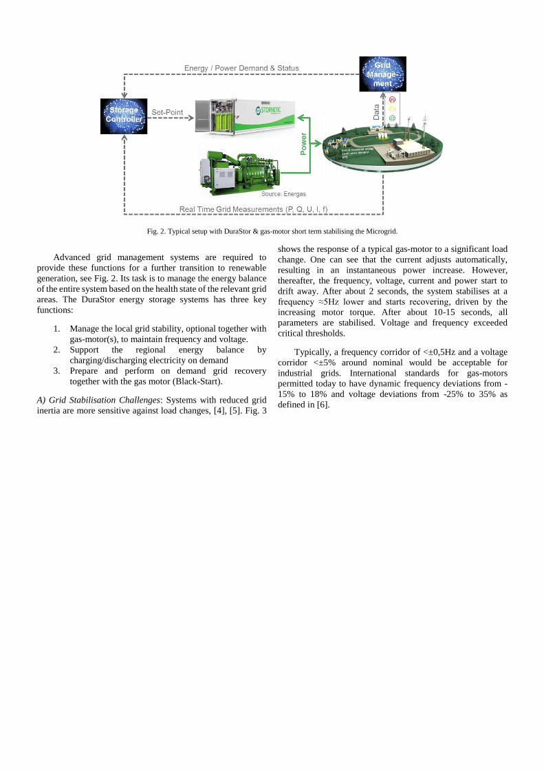
Fig. 2. Typical setup with DuraStor & gas-motor short term stabilising the Microgrid.
Advanced grid management systems are required to
provide these functions for a further transition to renewable
generation, see Fig. 2. Its task is to manage the energy balance
of the entire system based on the health state of the relevant grid
areas. The DuraStor energy storage systems has three key
functions:
1. Manage the local grid stability, optional together with
gas-motor(s), to maintain frequency and voltage.
2. Support the regional energy balance by
charging/discharging electricity on demand
3. Prepare and perform on demand grid recovery
together with the gas motor (Black-Start).
A) Grid Stabilisation Challenges: Systems with reduced grid
inertia are more sensitive against load changes, [4], [5]. Fig. 3
shows the response of a typical gas-motor to a significant load
change. One can see that the current adjusts automatically,
resulting in an instantaneous power increase. However,
thereafter, the frequency, voltage, current and power start to
drift away. After about 2 seconds, the system stabilises at a
frequency ≈5Hz lower and starts recovering, driven by the
increasing motor torque. After about 10-15 seconds, all
parameters are stabilised. Voltage and frequency exceeded
critical thresholds.
Typically, a frequency corridor of <±0,5Hz and a voltage
corridor <±5% around nominal would be acceptable for
industrial grids. International standards for gas-motors
permitted today to have dynamic frequency deviations from -
15% to 18% and voltage deviations from -25% to 35% as
defined in [6].

Fig. 3. Dynamic response of a gas-motor to a load step.
Additionally, it is predicted that in future even in
interconnected grids, some regions have to have the ability to
operate in island mode [1], [7]. This will be required to avoid
larger black-outs when grids become unstable and will also be
needed to restore grids after local or regional failures. In the
future, local grids, grids with more decentralized renewable
generation and with less system inertia, will need to have more
elasticity to support grid restoration. This requires that local or
micro-grids should support:
• Grid following operation when grid connected
supporting regular grid codes and providing regular
grid services
• Swift movement from grid following into island mode
when the superordinate grid gets instable and if
required by grid management
• Formation and operation of a micro-grid, with
different grid codes, with operation of critical
equipment like gas-motor and energy storage
• Resynchronization and reconnection to the public grid
if required by the grid management system
The same demand occurs for “private” micro-grids like
industrial grids that want to operate in island mode during
instabilities. Studies have shown that the fast response time of
flywheel and battery storage systems, compared to
conventional generators, have a positive influence on grid
stability and ancillary service costs [8] while also reducing the
CO2 emission by some percent [9].
III. HIGH-LEVEL SOLUTIONS
Today multiple solutions are in discussion to cover the
upcoming problem of grid stability due to reduced inertia. In
general, the assumption is that systems will become more and
more decentral and with smaller individual power producers.
First steps have been taken to force renewable sources to
provide system stability services. Table 1 provides an overview
of discussed solutions providing short-term grid stabilisation
services.
Immediate Power Adjustment
Delayed Frequency Change

TABLE I SUITABILITY OF VARIOUS TECHNOLOGIES STABILIZING THE GRID
Solution Pros. Cons.
Adjust renewable
generation at over and
under-frequency
(Curtailment)
• Low cost solution mainly introduced by
software changes
• Relatively easy to implement
• Provides service proportional to the
renewable share
• Number of installations is increasing.
• It’s only available during renewable
generation => less predictable and not
manageable
• It can only provide low frequency
support if continuous curtailment is
accepted
• Increased pay-back times because of
opportunity losses
• It is not immediate as it needs to balance
the interest of energy supply vs. system
stability (up to 1 second delay).
Use of gas-motors like
Biomass or CHP
systems
• It’s real inertia, thus, instantaneous
• Biomass is more baseload power, and
therefore, predictable and manageable
• Number of installations are increasing
• Resynchronization is possible
• Black-Start is possible.
• Due to the slow response characteristic
of gas motors and little mechanical
inertia, service is limited
• If providing primary frequency
regulation, the owner can have
opportunity losses.
Battery storage • Can be combined with mid- and long-
term storage
• Relative responsive (100 to 1,000 ms),
and thus, good fast frequency control.
• No real inertia and does not provide
support for the first 100 to 500 ms
• In continuous frequency control load
cycles reduce battery lifetime.
Synchronous
flywheels • It’s real inertia, and thus, instantaneous
• Provide a lot of power for a few seconds.
• Can only provide energy for a few
seconds (H-Factor < 2 s)
• Relatively expensive and specialised
• Continuing losses.
EnWheels (non-
synchronous
flywheels)
• Provide a lot of power for a few minutes
• Very responsive (toggle from charging to
discharging in 10 ms, and thus, reliable
and very fast frequency control
• Load cycle resistance and long lifetime
• Support resynchronization and
Blackstart.
• Non-synchronous grid inertia
• Limited to a few minutes of grid support.
Hybrid solutions with
EnWheels and
Generators or
turbines
• Provide real synchronous inertia
• Very Responsive (toggle from charging
to discharging in 10 ms, and thus,
reliable and very fast frequency control
• Load cycle resistance and long lifetime
• Resynchronization and Blackstart
possible.
• In combination with gas motors only
providing synchronous inertia as long the
gas motor is in operation
• Continuing losses of around 7% to 10%
Error! Reference source not found. shows the benefit of
synchronous reserve, but also the benefit of very fast
responding systems on grid stability. The combination of both
would allow enhancing grid stability at the lowest investment
levels. In addition, most of these systems can be installed in a
decentralized manner, solving local constraints and being more
adaptive.
IV. SYSTEM DESIGN
To judge the capabilities of the various solutions, it is
necessary to understand where constraints originate. This
finally will also explain the physical gap between synchronous
and non-synchronous solutions, and the remaining risks of
losing more and more synchronous reserve.
A) Functioning of Synchronous Generators: A rotor with a
magnetic field is passing stator coils connected to an AC supply
producing a rotating field. At synchronous speed (the grid
frequency (f)), the rotor poles lock to the rotating magnetic
field. The rotor is typically driven by a motor or turbine that
creates the required mechanical energy, power, and torque. See
Fig. 4.
Fig. 4. Schematic of the power transfer from Motor/Turbine to Generator and
Grid.
Motor or Turbinemechanical power Shaft
Gri
dGeneratorelectrical power
If load changes, the changed current also flows through the
stator coils of the generator, which changes the electro-
magnetic counter-field (BStator), and with this, the electro-
magnetic torque of the stator (Tel), see next formula with k
being a generator constant.
𝑇𝑒𝑙 =𝑘
2 ∗ 𝜋 ∗ 𝑓∗ 𝐵𝑆𝑡𝑎𝑡𝑜𝑟 ∗ 𝐵𝑅𝑜𝑡𝑜𝑟 ∗ sin 𝛿(𝑡) (1)
To achieve again a new electro-magnetic energetic
equilibrium, the angle (sin ) changes until the magnetically
transferred energy equals the electrical energy. This will
change the electrical torque (Tel). Now the equilibrium between
the electrical Torque (Tel) and the mechanical torque (Tmech) of
the motor/turbine gets disturbed. As a consequence, the
speed/frequency of the generator changes. This change will
only stop when the mechanical torque (Tmech) is adjusted to the
electrical torque and a new equilibrium is achieved. The
mechanical part of this process is described by the “swing
equation” [10]. J is the mechanical inertia of the turbine-
generator set.
𝐽 ∗ �̇�(𝑡) = 𝑇𝑚𝑒𝑐ℎ − 𝑇𝑒𝑙 (2)
The formula describes that mechanical energy is taken out
of the rotating mechanical inertia (J) until by other
means/adjustments the mechanical and electrical torque
equilibrium is achieved again. Consequently, the shaft
accelerates or decelerates (�̇�). In a micro-grid this influences
the grid frequency immediately because J can be small
compared to the torque change.
This service is called “Synchronous Grid Inertia” and is a
very important factor for grid stability. The swing equation also
shows that the change of grid frequency (ω) is by definitions a
consequence of load change always being delayed compared to
the load step, also shown in Error! Reference source not
found..
A) Inverter Based Systems and Their Behaviour Stabilising
the Grid: All systems producing energy without using a
synchronous generator need inverters to deliver electrical
power into the grid. Examples are solar and battery systems as
well as most wind power systems or battery storage systems.
-400,0
-300,0
-200,0
-100,0
0,0
100,0
200,0
300,0
400,0
-2
-1
0
1
2
0,01
039
0,01
122
0,01
208
0,01
296
0,01
378
0,01
464
0,01
549
0,01
636
0,01
725
0,01
811
0,01
900
0,01
989
0,02
078
0,02
167
0,02
257
0,02
346
0,02
434
0,02
522
0,02
609
0,02
697
0,02
784
0,02
874
0,02
962
0,03
051
0,03
136
0,03
215
0,03
294
0,03
373
0,03
450
0,03
528
0,03
611
0,03
693
0,03
777
0,03
861
0,03
947
Vol
tage
[V]
PWM
Co
ntro
l Sig
nal
Time [s]
Phasor of Voltage plus PWM-Pattern
PWM + PWM - Voltage U [V]
-400,0
-300,0
-200,0
-100,0
0,0
100,0
200,0
300,0
400,0
0,0
1039
0,0
1127
0,0
1220
0,0
1309
0,0
1399
0,0
1490
0,0
1581
0,0
1672
0,0
1763
0,0
1859
0,0
1952
0,0
2049
0,0
2143
0,0
2239
0,0
2331
0,0
2425
0,0
2518
0,0
2611
0,0
2703
0,0
2797
0,0
2892
0,0
2985
0,0
3079
0,0
3167
0,0
3249
0,0
3333
0,0
3416
0,0
3498
0,0
3586
0,0
3672
0,0
3759
0,0
3850
0,0
3940
Vol
tage
U, V
, W [
V]
Time [s]
3 Voltage Phasor
Voltage U [V] Voltage V [V] Voltage W [V]
PWM Pattern
Sine
Zero Crossings
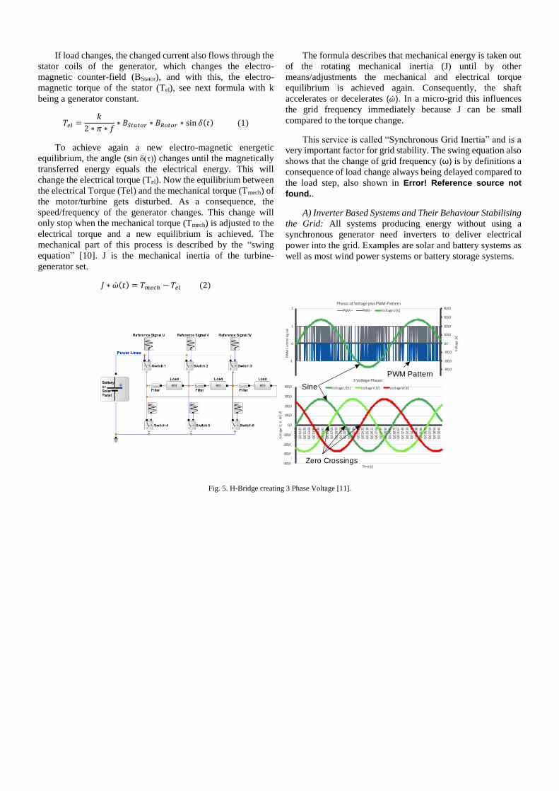
Fig. 5. H-Bridge creating 3 Phase Voltage [11].

The inverter uses DC current and voltage, and creates a sinus
like AC voltage and current using power electronic switches,
chopping the DC-current into rectangular pulses with a
moduled length. This method is called “Pulse Width
Modulation” (PWM). A typical design is shown in Fig. Based
on a reference signal for every phase, a dedicated PWM pattern
is generated that switches the semiconductors. Typically, grid-
connected inverters measure and predict constantly the three
grid phasors and create, out of this, the reference signal
controlling the semiconductors.
Measure
Set-Point Comp.
Bus-
delay
Bus-Delay
StorageDC-Bus
Inverter Measure
PID
Storage-Process
++--
Grid
Fig. 6. Typical control loop of an inverter based storage system.
As long as conditions are not changing significantly, the
phasors can be predicted. If conditionschange, some
interpolations are needed before the phasor change is
characterised properly in amplitude, angle, and speed. These
measurements take time. Therefore, inverter driven systems
have the following fundamental difference compared with
synchronous generators:
• Inverter based systems always respond with a delay
and do not support the grid immediately
• All interactions and changes are based on
computations, are conscious and not coming from
physical effects
• Depending on the DC source additional reaction
delays can exist
• The sine is not perfect and can have harmonics.
Table II highlights the differences between synthetic
inertia and synchronous inertia at different points in time after
an event occurs. Compared to the case with high grid inertia,
inverter based systems have disadvantages within the first
second. These disadvantages are strongly related to the
response time of the system. Systems with short response times
and short dead times compensate fast. Systems with response
times longer 1,000ms do not contribute to short term grid
stability. Dependent on the storage/generation technology as
part of the inverter-based system the grid is allowed to recover
faster compared to pure synchronous reserves.
TABLE II
GRID SUPPORT OF SYNCHRONOUS AND INVERTER BASED GENERATION AT VARIOUS TIMEFRAMES
Timeframe1 Synchronous Inertia2 Inverter Based (synthetic)
Inertia3
0 ms up to ≈
30 ms
• Provides required power based on
Ohm’s law
• Grid frequency change hardly visible.
• No support.
≈ 30 ms up
to ≤ 1 s
• Provides required power
• Frequency starts changing visibly.
• Provides power ramping up,
based on technology and control
algorithm within ≈ 50 ms up to
≤ 1 s.
≤ 1 s up to ≈
5 s
• Provides required power
• Depending on load step strong change
of frequency visible
• Mechanical torque starts to adjust.
• Delivers required power
• Stops frequency drift
• Based on control algorithm
frequency, drift starts to recovers.
≈ 5 s up to ≈
30 s
• Provides required power
• Torque adjustment stops frequency
drift.
• Delivers required power
• Grid frequency is recovering.
≈ 30 s up to
≈ 5 min
• Provides required power
• Torque adjustment helps to recover
frequency.
• Delivers required power
• Grid frequency is recovered.
For grid services, it is key to further reduce the reaction
time of the inverter based systems, allowing to further close the
gap to synchronous generation within the first second and allow
stable grid operation with less synchronous generation.
1 Timeframe can vary based on technology and vendor. Fig.s are indicative representing typical solutions existing today or requirements from typical grid codes. 2 Statements is assuming sufficient power installed 3 Statements is assuming sufficient power installed. Fig.s are indicative representing typical solutions existing today.
B) Improved Responsiveness of Inverter Based Storage
Systems: Table II show the benefits of fast responding inverter
based resources for grid stability. Storage systems, in
particular, allow compensating bi-directional load changes
while currently renewable generation curtailment is mainly
used to stabilise high frequency scenarios. Fast response with
little delay time helps grids recovering because of two main
effects:
• Fast adjustment of power obviously leads to faster
achieving a new equilibrium giving grid stability
• Little response and delay times allow for faster and
more robust control-loop designs.
To understand system response and its impact on grid
frequency, it is helpful to analyse the system, including
measurements, computation, system component responses, and
control loop designs.
Critical processes are the grid measurements, the
computation times and the storage response. Depending on the
measurements methods chosen, measurement times can vary
from < 10 ms up to > 0.5 s. The response of the storage itself depends on technologies and has often limited ramp rates or
slopes. Overall, control loops can get very long, limiting the use
of energy storage systems for frequency regulation; but it is
possible to design fast control systems.
To achieve shorter to very short reaction times, system
operators have to make a choice. Currently non-synchronous
frequency regulation services are typically designed with a
corridor of no action (dead band), followed by a proportional
correction action (P-Controller). A long slope time (I-
Controller with long integration time) is usual before a service
is fully triggered. A different control behaviour is needed to
replace inertia with synthetic inertia, acting proportionally with
reasonably short integration time, but in addition, maybe even
acting differentially on the rate of change (PI(D)-Controller).
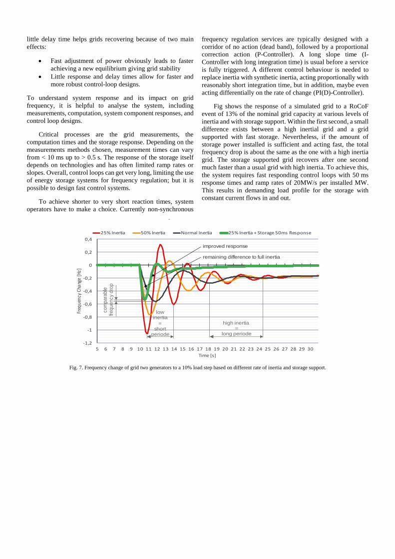
Fig shows the response of a simulated grid to a RoCoF
event of 13% of the nominal grid capacity at various levels of
inertia and with storage support. Within the first second, a small
difference exists between a high inertial grid and a grid
supported with fast storage. Nevertheless, if the amount of
storage power installed is sufficient and acting fast, the total
frequency drop is about the same as the one with a high inertia
grid. The storage supported grid recovers after one second
much faster than a usual grid with high inertia. To achieve this,
the system requires fast responding control loops with 50 ms
response times and ramp rates of 20MW/s per installed MW.
This results in demanding load profile for the storage with
constant current flows in and out.
-1,2
-1
-0,8
-0,6
-0,4
-0,2
0
0,2
0,4
5 6 7 8 9 10 11 12 13 14 15 16 17 18 19 20 21 22 23 24 25 26 27 28 29 30
Freq
uenc
y Ch
ange
[Hz]
Time [s]
-
25% Inertia 50% Inertia Normal Inertia 25% Inertia + Storage 50ms Response
low inertia
=short
periode
high inertia=
long periode
co
mpara
ble
freque
ncy
dro
p
improved response
remaining difference to full inertia
Fig. 7. Frequency change of grid two generators to a 10% load step based on different rate of inertia and storage support.
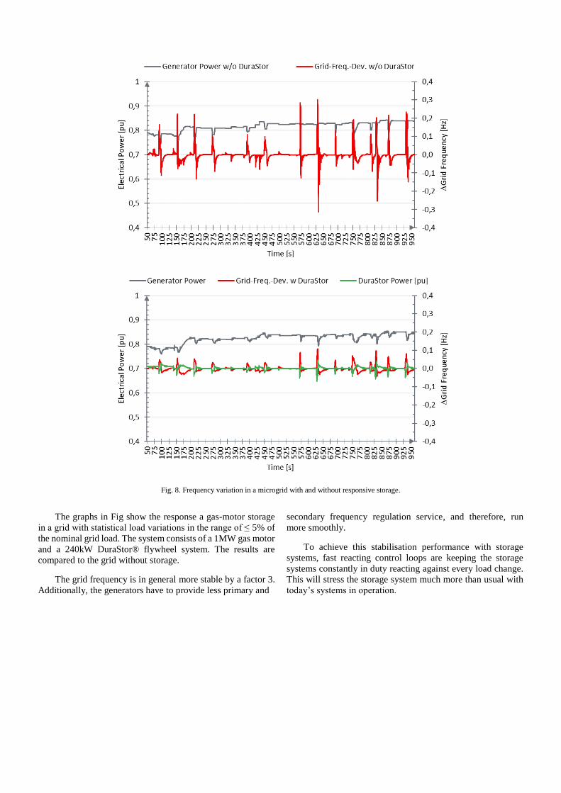
Fig. 8. Frequency variation in a microgrid with and without responsive storage.
The graphs in Fig show the response a gas-motor storage
in a grid with statistical load variations in the range of ≤ 5% of
the nominal grid load. The system consists of a 1MW gas motor
and a 240kW DuraStor® flywheel system. The results are
compared to the grid without storage.
The grid frequency is in general more stable by a factor 3.
Additionally, the generators have to provide less primary and
secondary frequency regulation service, and therefore, run
more smoothly.
To achieve this stabilisation performance with storage
systems, fast reacting control loops are keeping the storage
systems constantly in duty reacting against every load change.
This will stress the storage system much more than usual with
today’s systems in operation.

Fig. 9. Temperature inside a battery cell pack operating in continuous stabilisation mode [15], [16], [17].
V. BUSINESS CASE
The challenge with energy storage business cases for
frequency regulation is the fact that they need to replace
existing generation technologies typically operating for many
years and often fully depreciated. In many countries, steam
power plants are providing this service today, and in some
countries like Ireland, some steam units are already declared as
must-run-systems for grid stability.
Economically, the fast reacting storage investment needs
to be valued against the must-run cost of generators kept online
for grid stability purposes. Steam power-plants today have
boundary costs in the area of 40€/MWh when running partial
load [12], while diesel generators have operating costs of >
100€/MWh [13], and gas-motors are around 60€/MWh. Most systems cannot produce less than 30% of the nominal power.
Assuming in a micro-grid a 300kW gas-motor could be shut
down because it’s must-run capacity is not needed anymore for
grid stability purpose, it would save around 160k€ operating
costs per year (365days*24h*0.3MW*60€/MW).
To replace the must-run in this example, around 250kW of
storage capacity is needed. At capital costs less than
1,000€/MW, break even can be achieved in less than 2 years
with high power quality allowing a transition into energy
production with much less CO2 emissions.
Experience exists with battery and flywheel storage
systems providing frequency stabilisation service mainly in the
United States and Ireland [3]. The PJM grid has a relatively
demanding load characteristic [14], but still less demanding
than needed to replace the real inertia as described in this
document.
Because of the extreme cyclic profile needed for short-
term grid stabilization, aging of storage technology is the main
challenge. The lifetime of batteries is mainly driven by
temperature coming from constant load flows and inner
resistance rather than from energy exchange. Error! Reference
source not found. shows that already after a few hours in
operation battery temperature becomes quite high peaking
>40°C (>105F) and resulting in replacement patterns <5 years.
Nevertheless, batteries lifetime is close to the payback period
giving an advantage for flywheels systems lasting significantly
longer.
Another advantage of flywheels vs. batteries is the
increased specific power ramp rate of flywheels. Flywheels can
provide full power in less than 50 ms, whereas batteries
typically ramp within 200 to 500 ms. The specific ramp rate per
installed MW for Stornetic flywheels is 1MW/0.05s=20MW/s,
compared to 1MW/0.2= max 5MW/s for batteries.
Further reductions are possible with the development of
more powerful flywheels systems offering system cost below
600k€/MW in the near future. Because of the extended lifetime,
flywheel technology additionally offers higher return on
investments as for example shown in [17].
VI. OUTLOOK
This paper shows the capabilities of storage systems on
short-term electricity grid stabilization. With more and more
renewable energy systems in the grid replacing conventional
turbines, this topic becomes more and more relevant.
Independent from the storage technology chosen, fast response
times are key if today’s grid stability criteria should be
maintained in the future. Today, research starts to focus on this
topic, but needs to be intensified. The following areas
especially require further research and development work:
• AC/DC grid inverter responsiveness requiring
improved control loop design and faster data
acquisition
• AC/DC grid inverter power ratings, requiring higher
current and voltage levels in combination with fast
switching times maybe using SiC semiconductor
technologies
• Fast grid frequency detection with improved
metrology algorithms and predictors.
VII. STORNETIC GMBH
Stornetic GmbH, a Germany based company, is building
flywheel energy storage systems called DuraStor®. Stornetic
is introducing hybrid energy storage solutions to service
multiple grid services. The technology is characterised by its:
• Proven safety
• Durability, designed to operate continuously at 100%
power
• Responsiveness to load changes
• Full power and capacity throughout the lifetime
• Efficiency
• Containerized system for quick installation or
relocalization
REFERENCES [1] RegioNETZ GmbH, Eschweiler, Germany, “QUIRINUS –
Regionales Virtuelles Flächenkraftwerk für Versorgungs-sicherheit
und Stromnetzstabilität,” 2017. [Online]. Available:
https://www.leitmarktagentur.nrw/lw_resource/datapool/_items/ite
m_414/pdb_kvk-1-012.pdf
[2] PR Newswire, (2016) “EDF and STORNETIC Start Project on
Advanced Smart Grids Storage Solutions” [Online]. Available: http://www.prnewswire.com/news-releases/edf-and-stornetic-start-
project-on-advanced-smart-grids-storage-solutions-601626585.html
[3] EirGrid Group, (2015). DS3 Programme. [Online]. Available: http://www.eirgridgroup.com/how-the-grid-works/ds3-programme/
[4] C. Rehtanz, M. Greve, T. Noll, and J. Schwippe, “Bedarfund
Erbringung von Momentanreserve 2030,” German Energy Agency (DENA), Berlin, Germany, article no. 9142, 2016.
[5] Renewable Energy Federation, The Integration of Renewable Energy
Sources Into the Distribution Grid. German, H. Loew. Berlin, Türk-Alman Enerji Inovasyon Forumu 2013 : Bunderverband Eneuerbare
Energie e.V., 2013.
[6] International Organization for Standardization. Reciprocating internal
combustion engine driven alternating current generating sets - Part 5:
Generating sets. ISO 8528-5. 2013. ISO/TC 70 Internal combustion engines, Beijing, China
[7] ENTSO-E. (2014). Current practices in Europe on Emergency and
Restoration: Drafting Team for the Network Code on Emergency and Resoration. [Online]. Available:
https://www.entsoe.eu/Documents/Network%20codes%20documents/N
C%20ER/140527_NC_ER_Current_practices_on_Emergency_and_Restoration.pdf
[8] K. Vu, R. Masiello, and R. Fioravanti, “Benefits of fast-response storage
devices for system regulation in ISO markets,” in Proc. 2009 IEEE Power & Energy Society General Meeting, pp. 1-8.
[9] M. Atanacio, R. Fioravanti, W. Katzenstein, and K. Vu, “Emission II
study of advanced storage used for frequency regulation,” Sandia National Laboratories, Albuquerque, NM, Sandia Negotiation 96362,
2012.
[10] E. Ørum, M. Kuivaniemi, M. Laasonen, A. I. Bruseth, E. A. Jansson, et al., “Nordic report furture system inertia,” European Network of
Transmission System Operators for Electricity (ENTSO-E), Brussels,
Belgium, 2013.
[11] Steinbeis, S. Rupp, “Modellierung von Analgen und Systemen, Teil 2 -
Antriebe und Systeme,” Baden-Wuerttemberg Cooperative State
University, Center for Advanced Studies, Heilbronn, Germany, rep. no. TM20305.2, 2018.
[12] P. Graichen and M. M. Kleiner, “Erneuerbare vs. fossile Stromsysteme:
ein Kostenvergleich,” Agora Energiewende, Berlin, Germany, rep. no. 105/02-A-2017/DE, 2017.
[13] J. Irlenborn, “Simulationsprogramm zur Optimierung eines Inselnetzes
mit Photovoltaikanlagen, Dieselgeneratoren und Batteriespeichern, ” M.S. thesis, Univ. of Applied Sciences, Technical Univ. of Cologne,
Cologne, Germany, Jul. 2014.
[14] PJM, (2017) PJM - Synchrophasor Technology. [Online] Available: http://www.pjm.com/markets-and-operations/ops-
analysis/synchrophasor-technology.aspx
[15] NREL, K. Smith, et. al., “Predictive Models of Li-ion Battery Lifetime,” in Proc. IEEE Conf. on Reliability Sci. for Advanced Materials and
Devices, 2014, NREL/PR‐5400‐62813.
[16] Renault SAS, P. Gyan, “Battery aging tests and modelling under calendar, cacling and mixed conditions,” in Proc. IQPC 2nd Conf.
Automive Battery Manage. Syst., 2016.
[17] R. vor dem Esche and R. Tudi, “Benefits of hybrid storage system with
flywheels,” Stornetic GmbH, Jülich, Germany, Oct. 2016. doi:
10.13140/RG.2.2.29623.93606