Nuclear Weapons Sources: un.org/disarmament/ fas.org ctbto.org jfklibrary.gov nato.int defense.gov.
Upload
truongtramCategory
view
217download
0
I. .
,, J .J
An Affum;ti;e Action/Equal Opportunity Employer
The four most recent reports in this series,unclassified, are LA-6834-PR, LA-6982-PR,LA-7328-PR, and LA-7587-PR.
This work was supported by the US Departmentof Energy, Office of Inertial Fusion.
Photocomposition by Kathy Valdez md .ioni Powell
DISCLAIMER
This report was prcptied as an account of work sponsored by an agency of the United States Govern-ment. Neither the United Stxlc$ Government nor anY agency thereof, nor any of their employies,makes any vrumnty, chpre$ or implied, or resumes any legal tiabtity or responsibility for the acc’ur-
aCY, COmPltlenCSS, Or usefulness of any information, Ippmntus, product, or proccs! disclosed, or rep-resents that its use would not infringe privxtely owned rights. Rcferencc herein to any spccitic tom.merciai product, process, or service by trade name, trademwk, manufadurer. or othawise, does notnecessarily constitute or imply its endorsement, recommendation, or famring by the United SlatesGovernment or anl agency thcrmf. The views and opinions of authors expressed herein do not nec-essarily state or reflect those O( the United Slates Govanment or any agency there.af.
UNITED STATES
DEPARTMENT OF ENERGY
CONTRACT W-7405 -ENG. 36

LA-7755-PRProgress Report
UC-21Issued: November 1980
Inertial Fusion Program
July l— December 31, 1978
Roger B. Perkins and theLaser Fusion Program Staff
Compiled by
Frederick Skoberne

CONTENTS
ABSTRACT . . . . . . . . . . . . . . . . . . . . . . . . . . . . . . . . . . . . . . . . . . . . 1
SUMMARY . . . . . . . . . . . . . . . . . . . . . . . . . . . . . . . . . . . . . . . . . . . . 2
I.
II.
III.
IV.
C02 Laser Program . . . . . . . . . . .. OO. OO. O.OOO. ...oo.oo.eo..~
COz Laser Technology . . . . . . . . . . . . . .. OO. OOO... . .. OOOOOO. O 3
Experiments, Diagnostics, and Military Applications . . . . . . . . . . . . . . . . . . . . 3Theoretical Support md Direction . . . . . . . . . . . . . . . . . . . . . . . . . . ...4
Laser Fusion Target Fabrication . . . . . . . . . . . . . . . . . . . . . . . . . . . ...5
Applications of Laser Fusion Systems Studies . . . . . . . . . . . . . . . . . . . . . . . 6
CO, LASER PROGRAM . . . . . . . . . . . . . . . . . . . . . . . . . . . . . . . . . 7
Gemini System . . . . . . . . . . . . . . . . . . . . ..O.O. . . 00 . .0000..07
Helios System . . . . . . . . . . . . .. 00 . . . . ..O.. . . . ...000000.0.3
References . . . . . . . . . . . . . . . . . . . . . . . . . . . . . . . . . . . . . . . . . . 13
ANTARES—HIGH-ENERGY GAS LASER FACILITY . . . . . . . . . . . . . . . . 14
Introduction . . . . . . . . . . . . .. O. O.. O...... . . . . . . . . 0.0.00.14
Optical System . . . . . . . . . . . .. OOO. .. O. 00 . . . . . . . . . .00.00.14
Front-End System . . . . . . . . . . . . .. OOO. O..O.O. . . 00 . 00 .000..16
Power-Amplitier System... . . . . . . . . . . . . . . . . . . . . . . . . . . . . . ...20
Energy Storage System... . . . . . . . . . . . . . . . . . . ..000.00000..023
Target System . . . . . ..e. . . . .. OOOO. .. OO..OO . 00 . . . ..0.00.25
Controls System . . . . . . . . . . . . . . . . . ..OOO.. . 00 . 0 . . . .000.0.26
HEGLFSite and Structures. . . . . . . . . . . . . . . . . . . . . . . . . . . . . . ...30
COZLASER TECHNLOGY . . . . . . . . . . . . . . . . . . . . . . . . . . . . . ...32Propagation Studies . . . . . . . . . . . . . . . . . . . . . . . . . . . . . . . . . . ...32
Saturable-Absorber Recovery. . . . . . . . . . . . . . . . . . . . . . . . . . . . . ...35
High-Etllciency Phase-Conjugate Reflection in Germanium mdh Invetied COZ . . . . . 37
CalculationofSmall-SignalGtin CoefXcientsinCOz . . . . . . . . . . . . . . . . . . . . 40
Direct Measurement ofNodinem Dielectric Properties in Germmium . . . . . . . . . . . 41
Subnanosecond Extinction ofCOz Laser Signals via Bulk
Photoionization in Germanium . . . . . . . . . . . . . . . . . . . . . . . . . . . ...43
High-Pressure Enrichment ofLightIsoto~s . . . . . . . . . . . . . . . . . . . . . . . . 44
References . . . . . . . . . . . . . . . . . . . . . . . . . . . . . . . . . . . . . . . ...45
TARGET EXPERIMENTS, DIAGNOSTICS, AND MILITARY APPLICATIONS . . 47
Experiment s . . . . . . . . . . . . . . . . . .. OO. OO..O . .. O....O. 47Diagnostic Development . . . . . . . . . . .. OO. .O..O. .o..000000~~~57
Military Applications . . . . . . . . . . . . . . . . . . . . . . . . . . . . . . . . . ...73
References . . . . . . . . . . . . . . . . .. OO. .O..O. . . . . . . 000 ..00..80
v
V. LASER FUSION THEORY AND TARGET DESIGN . . . . . . . . . . . . . . . . . . 81
Theoretical Support . . . . . . . . . . . . . . . . . . . . . . . . . . . . . . . . . . ...81
Target Design . . . . . . . . . . . . . . . . . . . . . . . . . . . . . . . . . . . . . ...89
Code Development . . . . . . . . . . . . . . . . . . . . . . . . . . . . . . . . . . ...89
References . . . . . . . . . . . . . . . . . . . . . . . . . . . . . . . . . . . . . . 0 . . 0 91
VI. LASER FUSION TARGETFABRICATION . . . . . . . . . . . . . . . . . . . . . . . 93
Introduction . . . . . . . . . . . . . . . . . . . . . . . . . . . . . . . . . . . . . . . . . . 93
Target Fabrication . . . . . . . . . . . . . . . . . . . . . . . . . . . . . . . . . . . ...94
Inorganic Coatings Development . . . . . . . . . . . . . . . . . . . . . . . . . . . ...98
Organic Coatings Development . . . . . . . . . . . . . . . . . . . . . . . . . . . . ...101
Organometallic ~oatings Development . . . . . . . . . . . . . . . . . . . . . . . . . . . . 105
Polymer Foam Development. . . . . . . . . . . . . . . . . . . . . . . . . . . . . ...105
Cryogenic Target Development. . . . . . . . . . . . . . . . . . . . . . . . . . . . ...106
References . . . . . . . . . . . . . . . . . . . . . . . . . . . . . . . . . . . . . . . ...108
VII. APPLICATIONS OF LASER FUSION—FEASIBIL~Y AND SYSTEMS
STUDIES . . . . . . . . . . . . . . . . . . . . . . . . . . . . . . . . . . . . . . ..s109
Reactor Design Studies . . . . . . . . . . . . . . . . . . . . . . . . . . . . . . . . ...109
Integrated Plant Design Studies”. . . . . . . . . . . . . . . . . . . . . . . . . . . . ...118
Engineering Development Studies . . . . . . . . . . . . . . . . . . . . . . . . . . . ...121
References . . . . . . . . . . . . . . . . . . . . . . . . . . . . . . . . . . . . . . . ...127
VIII. RESOURCES, FACILITIES,AND OPERATIONAL SAFETY . . . . . . . . . . . . .128
Manpower Distribution . . . . . . . . . . . . . . . . . . . . . . . . . . . . . . . . ...128
operationalS afety . . . . . . . . . . . . . . . . . . . . . . . . . . . . . . . . . . . ...128
IX. PATENTS, PUBLICATIONS, AND PRESENTATIONS . . . . . . . . . . . . . . . . 129
Patents . . . . . . . . . . . . . . . . . . . . . . . . . . . . . . . . . . . . . . . . . ...129
Publications . . . . . . . . . . . . . . . . . . . . . . . . . . . . . . . . . . . . . . ...129
Presentations . . . . . . . . . . . . . . . . . . . . . . . . . . . . . . . . . . . . . ...130
vi

INERTIAL FUSION PROGRAM
July l—December 31, 1978
by
Roger B. Perkins and the
Laser Fusion Program Staff
ABSTRACT
Progress at Los Alamos Scientific Laboratory (LASL) in the development of high-
energy short-pulse COZ laser systems for fusion research is reported. Improvements to
LASL’S two-beam system, Gemini, are outlined and experimental results are discussed.
Our eight-beam system, Helios, was fired successfully on target for the fwst time, and
became the world’s most powerful gas laser for laser fusion studies. Work on Antares,
our 100- to 200-TW target irradiation system, is summarized, indicating that design
work and building construction are 70 and 48% complete, respectively. A baseline
design for automatic centering of laser beams onto the various relay mirrors and the op-
tical design of the Antares front end are discussed.
Optical phase conjugation as a means of automatic target alignment is summarized,
and we report on work with SF6-based gas isolators containing Hz, which may lead to
almost total recovery of isolator absorption in a few tens of nanoseconds. In experi-
ments with exploding-pusher targets, neutron yields exceeding 108 were obtained for the
first time with COZ radiation. Progress in the development of x-ray diagnostics is out-
lined, including the fast high-voltage triggering of our x-ray streak camera. Ultraviolet
spectroscopy of highly ionized beams yielded results that had not been observed
previously. Multiburst simulation and opacity experiments, part of our modest military
applications effort, are described. Improvements in calculational techniques, and results
of studies on optical loading of targets and their energy absorption by shifted laser foci
are presented. Significant problems in the fabrication of laser fusion targets culminating
in the successful manufacture of the 20-times-liquid-density target are outlined, and the
development of a heat-transfer code that calculates the nonuniformity of DT ice layers
on opaque inner target shells is discussed.
The results of various fusion reactor studies are summarized, as well as investigations
of synthetic-fuel production through application of fusion energy to hydrogen produc-
tion by thermochemical water splitting. Studies on increased efficiency of energy extrac-
tion in COZ lasers and on lifetimes of cryogenic pellets in a reactor environment are
summarized, as well as the results of studies on pellet injection, tracking, and beam
synchronization.
SUMMARY
(R. B. Perkins and
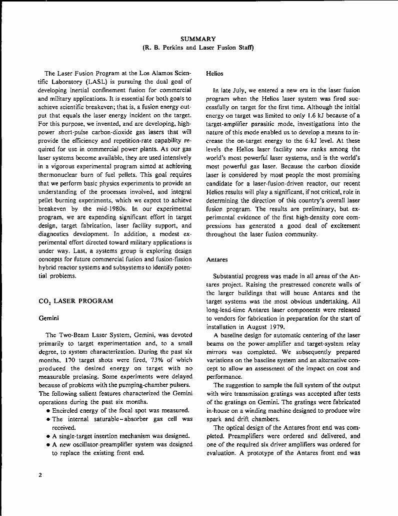
The Laser Fusion Program at the Los Alamos Scien-
tific Laboratory (LASL) is pursuing the dual goal of
developing inertial confinement fusion for commercial
and military applications. It is essential for both goals to
achieve scientific breakeven; that is, a fusion energy out-
put that equals the laser energy incident on the target.
For this purpose, we invented, and are developing, high-
power short-pulse carbon-dioxide gas lasers that will
provide the efficiency and repetition-rate capability re-
quired for use in commercial power plants. As our gas
laser systems become available, they are used intensively
in a vigorous experimental program aimed at achieving
thermonuclear burn of fuel pellets. This goal requires
that we perform basic physics experiments to provide an
understanding of the processes involved, and integral
pellet burning experiments, which we expect to achieve
breakeven by the mid- 1980s. In our experimental
program, we are expending significant effort in target
design, target fabrication, laser facility support, and
diagnostics development. In addition, a modest ex-
perimental effort directed toward military applications is
under way. Last, a systems group is exploring design
concepts for future commercial fusion and fusion-fission
hybrid reactor systems and subsystems to identify poten-
tial problems.
C02 LASER PROGRAM
Gemini
The Two-Beam Laser System, Gemini, was devoted
primarily to target experimentation and, to a small
degree, to system characterization. During the past six
months, 170 target shots were tired, 730/0 of which
produced the desired energy on target with no
measurable prelasing. Some experiments were delayed
because of problems with the pumping-chamber pulsers.
The following salient features characterized the Gemini
operations during the past six months.● Encircled energy of the focal spot was measured.
● The internal saturable- absorber gas cell was
received.● A single-target insertion mechanism was designed.
● A new oscillator-preamplifier system was designed
to replace the existing front end.
Laser Fusion Sta~
Helios
In late July, we entered a new era in the laser fusion
program when the Helios laser system was fired suc-
cessfully on target for the first time. Although the initial
energy on target was limited to only 1.6 kJ because of a
target-amplifier parasitic mode, investigations into the
nature of this mode enabled us to develop a means to in-
crease the on-target energy to the 6-kJ level. At these
levels the Helios laser facility now ranks among the
world’s most powerful laser systems, and is the world’s
most powerful gas laser. Because the carbon dioxide
laser is considered by most people the most promising
candidate for a laser-fusion-driven reactor, our recent
Helios results will play a significant, if not critical, role in
determining the direction of this country’s overall laser
fusion program. The results are preliminary, but ex-
perimental evidence of the first high-density core com-
pressions has generated a good deal of excitement
throughout the laser fusion community.
Antares
Substantial progress was made in all areas of the An-
tares project. Raising the prestressed concrete walls of
the larger buildings that will house Antares and the
target systems was the most obvious undertaking. All
long-lead-time Antares laser components were released
to vendors for fabrication in preparation for the start of
installation in August 1979.
A baseline design for automatic centering of the laser
beams on the power-amplifier and target-system relay
mirrors was completed. We subsequently prepared
variations on the baseline system and an alternative con-
cept to allow an assessment of the impact on cost and
performance.
The suggestion to sample the full system of the output
with wire transmission gratings was accepted after tests
of the gratings on Gemini. The gratings were fabricated
in-house on a winding machine designed to produce wire
spark and drift chambers.
The optical design of the Antares front end was com-
pleted. Preamplifiers were ordered and delivered, and
one of the required six driver amplifiers was ordered for
evaluation. A prototype of the Antares front end was
2

assembled in the old Single-Beam System area. Evalua-
tion and development of multiline oscillators and mul-
tipass amplifier geometries were planned for the
prototype.
We reactivated the power-amplifier prototype to
evaluate modifications in the Antares power-amplifier
design that were a result of the prototype program.
Reliability and control of the gridded cold-cathode gun
were improved. Stands, pressure vessels, and gun
parts —all long-lead-time items—for the power-amplifier
proper were promised for delivery in mid- 1979.
A firm, fixed-price contract for the engineering design
and fabrication of the Antares energy storage system
was awarded. All prospective vendors were willing to
quote on a fixed-price basis because a prototype unit had
been designed and tested by LASL. This prototype Marx
unit met the specified inductance requirements as well as
the basic voltage and energy requirements. In addition,
we developed a spark gap that transfers the charge and
current anticipated under fault conditions without
failure.
A design-construct contract for the Antares target-
chamber and vacuum system was also awarded. A uni-
que feature of this 1300-m3 system was the requirement
that the pumping units be cryogenic pods. The contrac-
tor was to proceed with the procurement of long-lead-
time items before final design review.
A tree-structured hierarchical architecture was
defined for the controls system. Detailed specifications
for the control computers and the communications
networks were released for competitive quotations.
Because construction was three months behind
schedule, the Department of Energy negotiated with the
Contractor to obtain beneficial occupancy of the Laser
Hall by mid-July 1979.
CO, LASER TECHNOLOGY
Optical phase conjugation continues to promise im-
proved beam quality and, possibly, automatic target
alignment in laser fusion systems. The use of longer ger-
manium samples permitted us to increase the observed
et%ciency of phase-conjugate wave generation from 2 to
20?/0. Also, conjugation in inverted COZ was seen for the
first time. In a hybrid arrangement where the COZ
medium helped to amplify the conjugated wave, efficien-
cies as high as 250V0 were measured without loss of
wave quality; the conjugated signal was stronger than
the original aberrated signal.
In related work designed to identify upper limits to im-
proving phase-conjugation efficiency in germanium by
using higher 10-~m intensities, we found that dense, bulk
plasma forms in intrinsic and in optical-grade ger-
manium above 200 MW/cm2 with associated free-carrier
densities as high as 2 x 10¹⁵/cm3 without permanent
material damage. However, p-type germanium did not
show these effects, renewing our interest in doped ger-
manium for conjugation.
In the gas-isolator development area, absorption
recovery was studied to better understand the potential
impact of these systems on the retropulse problem. We
found that the recovery rate of the SFc-based mixtures
depends only weakly on the saturating wavelength, and
slows with increasing optical fluence. However, by
adding Hz to the isolator mixture, the absorption at some
wavelengths recovered up to four times faster than
previously. The goal is to obtain almost total recovery of
isolator absorption in a few tens of nanoseconds.
Work on the reinfection laser prototype culminated in
demonstration of reliable operation at pressures up to
7600 torr. Results of a full characterization are reported,
including an operation reliability level of 99.95 during a
4000-shot sequence. This laser uses multiple passes to
generate energetic, subnanosecond pulses, and will be
used in the upgraded Gigawatt Test Facility (GWTF)
system.
A prototype of the GWTF was also characterized,
revealing some discrepancies between predicted and ob-
served propagation of subnanosecond multiline pulses.
Although predicted and observed extracted energies
agreed well in these tests for 1.0- and 0.5-ns fmal-
amplifier-input-pulse durations, the amplified pulse was
substantially broader than expected in the latter case.
Investigations begun this period include the first direct
measurement of the nonlinear 10-~m refractive index
(nz) in germanium via ellipse rotation and determination
of an upper limit to n2 in NaC1.
EXPERIMENTS, DIAGNOSTICS, AND MILITARY
APPLICATIONS
Experiments
The Helios laser has delivered previously unattainable
COZ laser power and energy to various targets.
Exploding-pusher targets served as a test of the new
facility, Neutron yields exceeding 108 were obtained for
the first time using C02 radiation. Plastic-coated glass
3
microballoon (GMB) targets designed to achieve high
fuel density were used in experiments aimed at targets
that are direct predecessors to fusion reactor targets.
These targets yielded sufficient neutrons for meaningful
parametric studies. High-density targets are difilcult to
diagnose, but initial experiments are providing informa-
tion consistent with our code calculations, which inten-
sities our diagnostic development efforts. The measured
speed of the fastest plasma protons at Helioc gave
further support to the expressions for hot-electron tem-
perature scaling, (11.2)1’3,where I is the ratio of focal
power vs unit area and L is the laser wavelength.
Diagnostics Development
The laser fusion program depends on our ability to
provide the instruments required. This is increasingly
true with large complex laser facilities and complex
targets.
During this reporting period, researchers tried to im-
prove the time resolution of neutron detectors so as to
more clearly separate the effects of ion temperature,
burn time, and run-in time on neutron spectra.
We have continued our vigorous program of x-ray
diagnostics development. Advances during the past 6
months clarified the triggering problems that have
plagued our x-ray streak camera work. We continued
fast high-voltage switching and triggering studies, which
should be useful for various diagnostics. Optical
telephotography with high resolution is evolving toward
the use of precisely timed optical probe beams.
Military Applications
Many feasibility studies were performed and a con-
siderable amount of data was collected during the past
two years using the two-beam glass laser.
The work on vacuum uv spectroscopy of highly
ionized metals has been concluded successfully, and we
obtained good, usable spectra of 22 metals. Many of the
results had never before been observed.
By contrast, the GEAR x-ray streak camera con-
tinued to have triggering problems in its internal cir-
cuitry, and no satisfactory data have been obtained.
Our equation-of-state (EOS) studies continue along
two distinct lines: impedance matching and shockwave
structure. We are using a fast, visible-light streak camera
to observe the shock front emerging from the rear of
multistep targets. Because the EOS is known for the sub-
strate, it can be deduced for the other layers. Work to
date has confirmed the feasibility of this technique.
The work on multiburst simulation and blast waves
used two-wavelength, visible-light holographic inter-
ferometry to observe one- and two-dimensional shocks
in air at various pressures. Experimental results to date
do not agree completely with calculations; i.e., gas den-
sities are in approximate agreement but electron densities
are not.
In the opacity experiments, we made progress in ob-
serving optical self-emission from the back of aluminum
foil targets simultaneously along a 30° and a normal line
of light. Analysis indicates a time-dependent anisotropy
in this emission.
THEORETICAL SUPPORT AND DIRECTION
The final report of the DOE Ad Hoc Experts’ Group
on Fusion (chaired by J. S. Foster) was issued in June
1978. One recommendation was that DOE establish a
full-spectrum design and theory effort at LASL to cover
the range of possible ICF (Inertial Confinement Fusion)
drivers, rather than COZ lasers only. We have presented
detailed plans to the DOE Office of Laser Fusion, and
anticipate that our effort will increase in that direction in
both depth and scope over the next year.
Significant work was performed in the four sections of
our theoretical group. Our unclassified targetdesign ef-
fort concentrated on the two Helios experiments: the 20-
Times-Liquid-Density Milestone experiment, also dis-
cussed in preceding reports, and the Exploding-Pusher
designs reported herein. An important achievement in
our code development effort was the preparation of an
off-axis ray-trace procedure, which modifies previous
treatment that caused us to overemphasize the non-
spherical optical loading and to overcorrect our two-
dimensional designs. Our laser physics work shows im-
proved calculations of the small-signal gain coefllcient in
C02 lasers.
Our theoretical target design studies produced results
on the optical loading and absorption by shifted laser
foci and on an extension of the suprathermal electron
scaling law; progress was also made in understanding
the coherent acceleration of hot electrons and their sub-
sequent transport in the plasma. Finally, we present
corrected calculations on the 10SS of fast ions from the
tails of the fuel-ion distribution in low-pR pellets.
4
LASER FUSION TARGET FABRICATION
General
Our ability to fabricate targets for laser fusion experi-
ments has increased in several areas, culminating in the
successful manufacture of the 20-times-liquid-density
(20XLD) target. In meeting this goal, we improved ourplastic-coating techniques and can now apply plastic
(CH) coatings up to 350 ~m thick with a peak-to-valley
surface smoothness better than 1 ~m to stalk-mounted
GMBs. In addition, we were able to remove the coated
stalk, leaving an imperfection of only - 1 pm in
smoothness and uniformity at the stalk location. Also,
we can coat about 100 unmounted, quality-selected
GMBs with up to 15 ~m of very-smooth-surfaced plastic
and recover essentially all the coated shells. Metal
coatings of gold and molybdenum up to 5 ~m thick were
applied to levitated GMBs by sputtering. Both unifor-
mity and surface smoothness are adequate for our
20XLD target.
In cryogenics, we developed a heat-transfer computer
code that calculates the nonuniformity of the DT ice
layer in a target frozen by the fast-isothermal-freezing
(FIF) technique. We are applying this code to targetswith opaque inner shells in which the DT layer cannot be
measured directly.
Target Assembly Progress
We supplied more than 1000 targets to our three
operating laser systems and made more than 100 parts
for diagnostic devices. About 320 targets werefabricated for Main-Sequence experiments. Another 340
were supplied for a wide variety of Target-Essentials and
Support Physics experiments, and over 400 were made
for military applications experiments. We completed the
development of fabrication techniques for 20XLD
targets to be tested on Helios.
During development of the 20XLD target, we
developed a micromachining technique to remove the
coated stalk from the plastic-coated GMB and to
remount the resulting spherical target. To fill these high-
aspect-ratio glass shells with 30 atm of DT fuel gas, we
measured the GMB crush strength and optimized our
pressure-staging procedures.
Metal Coatings Development
In preparation for fabricating the Rigel-B target
(20XLD with a metal pusher layer) we developed techni-
ques to coat small numbers of quality-selected GMBs
with metal layers. We applied coatings up to 5 ~m thick
of sputtered gold and molybdenum to GMBs levitated
by our gas-jet levitator. The surface smoothness of these
coatings is better than 1 ~m peak-to-valley.
To improve the quality of all-metal pushers, we are
trying to make free-standing, high-quality metal shells by
metal-coating a removable spherical mandrel. Spheres of
polymethyl methacrylate (PMMA) made by our droplet
generator technique were overcoated with -2 ~m of
CVD nickel and leached in solvent. Although some of
the resulting hollow shells were of high quality, some
crumpled without the mandrel support.
Plastic-Coatings Development
We finally discovered how to plastic-coat a few
preselected GMBs by low-pressure plasma polymeriza-
tion without losing them or fusing them to the coater in
the process. Up to 15 ~m of poly p-xylene was applied to
as few as 8 GM Bs, with 100% recovery and extremely
smooth surfaces. For the thicker coatings needed for the
20XLD target, we applied poly p-xylylene by the vapor-
phase pyrolysis technique in coatings up to 350 ~m
thick. Surface smoothness was improved by lowering the
deposition rate, applying a 20-nm-thick passivating layer
of aluminum to the GMB before coating, or by adding a
comonomer during deposition. Surfaces with < +0.2-Iun
peak-to-valley variation are achievable.All experiments to produce small-cell-size, low-density
plastic foam failed to achieve one of these requirements.
We are, therefore, reassessing foam fabrication methods
and investigating alternative buffer materials.
Organometallic Coatings Development
Because we cannot measure the uniformity of a DT
ice layer inside a metal pusher shell, we developed a
heat-transfer computer code to calculate the freezing
rate and DT shell nonuniformity for complex, multilayer,
multishell targets. Calculated nonuniformities for glass
5

shell targets were in good agreement with experimental
data. and we are trying to compare calculated and ex-
perimental data for different configurations of glass
shells.
Work on the cryogenic-target freezing apparatus for
Helios is under way. The present retraction speed of the
heat shield is 3 cm in 6.8 ms. which is probably fast
enough, but more work is needed on the shock absorber
system that stops the retracting shroud.
APPLICATIONS OF LASER FUSION SYSTEMS
STUDIES
In our reactor design studies we programmed the
mathematical description of the new plasma model
representing the magnetically protected reactor cavity
for use on the CRAY computer. We also investigated
methods of removing the significant amount of fuel-pellet
microexplosion energy by means of magnetic fields in a
magnetohydrodynamic (M HD) energy converter that
decelerates the ions without suffering excessive wall ero-
sion and even generates electric energy in the process.
The concept of absorbing the neutron energy at high
temperature in a blanket of boiling lithium-containing
metal was studied further and led to conceptual solutions
to the production of high-temperature process heat for
more efticient energy conversion.
Our studies of proliferation-resistant fuel cycles, based
on laser-driven IC F reactor technology, focused on
quasisymbiotic concepts that maximize tissile-fuel
production and minimize heat production.
Hydrogen production studies continued. They are
coordinated with a parallel study, supported by the Of-
fice of Fusion Energy, of thermochemical hydrogen
production. As part of this effort, we are also engaged in
process design of a bismuth-oxide electrother-
mochemical cycle.
Finally, in engineering development studies that attest
to the impact of advanced technologies on long-life,
high-repetition-rate ICF systems, we investigated means
of increasing the efficiency of energy extraction in COZ
lasers and calculated the lifetime of cryogenic pellets in a
reactor environment. Results of a study performed for us
by United Technologies Research Center on pellet injec-
tion. tracking, and laser beam synchronization are also
reported.
6

L CO, LASER PROGRAM
(G. Schappert)
Research and development programs on high-energy short-pulse COZ lasers began at
LASL in 1969. The first system, the Single-Beam System, was designed in 1971, began
operation in 1973, and was phased out in November 1977. Two large systems now
operating are the Two-Beam System called Gemini, and the Eight-Beam System called
Heiios. Target experimentation continued on Gemini, which will ultimately generate
pulses of 2 to 4 TW for target-irradiation experiments. Heiios became operational in
April 1978, and surpassed the design goal on June 21, 1978, with an output of 10 kJ at
a power level of -20 TW. The third system, Antares, is in the design and prototype
stage. This system, described separately in Sec. II, will generate laser pulses of 100 to
200 TW, with the objective of demonstrating scientific breakeven.
GEMINI SYSTEM
Introduction (J. P. Carpenter)
The Gemini System was devoted primarily to target
experimentation and, to a small degree, to system
characterization. During the past 6 months, 170 target
shots were tired and 73% of those produced the desired
energy on target with no measurable prelasing. Some ex-
periments were delayed by problems with the pumping-
chamber pulsers.
Laser Performance and Diagnostics (J. P. Carpenter, J.
J. Hayden, J. McLeod)
Measurements of encircled energy at the focal spot
showed that 70V0 of the total beam energy passed
through a 100-~m-diam pinhole. The Strehl ratio of
-0.25 derived from these data should improve substan-
tially with the addition of adaptive optics to the triple-
pass amplifiers. The adaptive-optics contract with
Hughes Research Laboratories entered the final
hardware phase.
The internal saturable-absorber gas-cell hardware was
received and inspected. This cell will house the defor-
mable recollimating mirror and should allow the delivery
of -1 TW to a target.
A target insertion mechanism that holds one target at
a time was designed and should be installed during the
second quarter of FY-79. This insertion system will per-
mit an unlimited number of target shots before breaking
the vacuum in the target chamber. The present target
wheel holds seven targets, but the vacuum must be
broken each time a new wheel is inserted.
The optical diagnostics facility can now measure pre-
and postpulsing power to 10-3 of the main pulse peak.
Oscillator-Preamplifier System (P. Goldstone, V.
Romero)
A new oscillator-preamplifier system, to be installed
early in FY-80. was designed to replace the existing front
end. A smoothing tube in addition to a switched-out os-
cillator. similar to that in the Helios system, will be used.
The new front end will be installed directly east of the
dual-beam module. Downtime will be minimal because
the present front end will remain operational until the
new system is installed. The new oscillator-preamplifier
room is shown in Fig. I-1.
Computer and Control System (S. Hackenberry, P.
Castine)
A computer simulation of our pulse-power capacitor
banks was started. This computer model, which should
simplify troubleshooting the pulse-power systems, uses
the NET-2 electronics code in the LASL Central Com-
puting Facility.

f24 f~
I
(clearance24 ft 8 in.)
-50 mJger beom
14 ft (cfei
t2 ft
-2 ft-
SA1
2ftuf-—
[
Beam.splitter
SF4(I ftul
~ 5ftby22ftteb
m
o!u)
I
PA 2
QOL8=100
#30:joc
Is100.120’
mJ I
$
I
*-+7
. .
1,/1 ‘
1
IIJJ.-,{
1,[
! “
‘\ I
i if=l.5m
PA1
~goL.
100
T
GEMINI
-3 ft -
SF35ATABS IUa?chinglenses
Photordroti
HaNe baom,from balow
).3 mJ
Ice 14 ft 4 in.)
~4ftby20-. table
1
Plosma tub
4-TEA
LTSG
- -a
d ?
1---
>SF2
r~
Injection ,rigg, rinmirrorrShield
Enclosure
,ONT END
N
I
Fig. I-1.
Gemini front end.
HELIOS SYSTEM
Introduction (J. S. Ladish)
The second half of 1978 marked the transition of the
Helios Laser Fusion Facility from construction to the
target-irradiation phase. After successfully firing the
laser in excess of the design output of 10 kJ into
calorimeters in June 1978 (FIST II), we decided to per-
form the Earliest Laser On-Target (ELOT) experiment
as soon as possible to gain experience and to become
familiar with the problems to be encountered in target-
irradiation tests. On July 27, 1978, ELOT was per-
formed at an on-target energy of 1.6 kJ and peak inten-
sity of just over 2 TW. The energy on target in that ex-
periment was limited because of a parasitic oscillation
mode caused by target feedback coupling to the am-
plifier gain medium.
The discovery of the parasitic mode triggered a con-
siderable effort to determine the feedback source at the
amplifier end, which would lead to its elimination. A
more suitable gas mix (Mix 907) was subsequently
developed for the amplifier saturable-absorber cell, and
the entrance beam tube used in the power amplifier was
removed. Also, we discovered a small, cone-shaped
depression, made by micromachining, at the center of
the large micromachined recollimating mirror. We used
Nextel paint to cover the depression because the cone
shape could act as a direct retroreflector, which would
produce parasitic paths involving the power-amplifier
gain medium and the target and/or diagnostics located
near the target. These modifications raised the on-target
energy to -6 kJ, equal to a peak power of -13 TW.
Although Helios is still in the shakedown phase, our
target experimentation has already provided valuable
new information regarding laser plasma interaction, and
has produced the first clear evidence of high-density
target implosions.
Target experimentation provided the principal excite-
ment during the second half of 1978, but most of our ef-
fort on Helios centered on many less exciting but equally
essential tasks, which are described below.
Front End (R. Carlson, R. Quicksilver, M. Weber)
The eventual requirement on beam simultaneity in
Helios has been set at + 1 cm (+33.3 ps). In preparation
for ELOT, the individual beam paths of the eight Helios
beams were adjusted for a beam simultaneity of +50 ps,
using a method similar to that used in the Gemini
system. The time of flight (TOF) of a front-end pulse to
the target was measured by the time difference between
the arrival of an optical pulse on a fast pyroelectric
detector (Molectron P5-00) referenced against the laser-
triggered spark-gap pulse (LTSG) of the three-stage
Pockels-cell system. The simultaneity measurements
were made wit h the LAS L-built 3-GHz oscilloscope to
record the optical and the LTSG pulses; a sweep calibra-
tion trace was added to each record to permit future tem-
poral deconvolution. About 1300 photographs were
taken yielding 200 records that met the pulse amplitude
requirements. The final data after several iterations of
path-length adjustment are presented in Table 1-1.
8

TABLE I-I
BEAM SIMULTANEITY
DATA FOR HELIOS
Path DifferencePrimary Beams from Mean (ps)
1A, 2B +51 * 40lB, 2A –24 + 33
3B, 4A –5 + 43
3A, 4B –23 + 61
This method of beam simultaneity measurement is
tedious and can cause several systematic errors.
Therefore, we developed, prototype, and tested an im-
proved technique that enables us to perform routine
measurements of beam simultaneity with a resolution of
less than +5 ps. Briefly, the cw (continuous wave) COZ
alignment laser in the front end will be modulated
electro-optically at 40 MHz and aligned onto a surrogate
reflecting sphere located in the target chamber. The
reflected return signal will be detected by a HgCdTe
detector located in the front end. The phase of this return
signal will be compared continuously to the phase of the
electrical signal that drives the modulator; this phase dif-
ference is proportional to the path difference. The system
is shown schematically in Fig. I-2. All equipment for this
system is on hand, and installation is -30V0 complete.
As part of our continuing improvements to the Helios
facility, we installed the following components:
● An improved oil-filled TEA oscillator and its
associated Invar-stabilized optical support struc-
ture;● Four motorized mirror slides at $patial Filter 2 to
permit repeatable injection of the krypton-ion visi-
ble alignment laser; and
. A 16-port voltage divider that provides an LTSG
pulse to Gallery West (our diagnostics setup) and to
the target diagnostics room for timing purposes.
Laser Physics (G. T. Schappert, J. S. Ladish, D. Casper-
son, R. F. Haglund)
The first eight-beam target shots on Helios were per-
formed during the second half of 1978. On July 27, the
entire system was fired for the ELOT test at reduced
PFN voltage (42 kV/stage) with 6 torr of Mix 804 in
each saturable-absorber cell. The total energy output on
these shots was 1.6 kJ and was limited because of
parasitic instabilities brought about when the entire
system was carefully aligned onto a GMB target. An in-
side view of the Helios target chamber is shown in Fig. I-“
3.
After these first successful low-energy eight-beam
shots, we performed a systematic study of the parasitic
thresholds with targets in place. We used several techni-
ques to identify the transitions involved in the self-lasing
from a target. An Optical Engineering spectrometer, and
Cd Te Modulotor
~“’:’’;athoq;~’g1 I I
h ?FOcusingLens
.p8640B#q~CdTeIletector
r4z5!5’::AFig. I-2.
Beam simultaneity schematic.

Fig. I-3.
Inside view of Helios target chamber.
later, 9- and 10-~m bandpass filters were placed at
Gallery West to detect any energy due to self-lasing.
However, these efforts were unsuccessful because of
alignment problems and because of the low energy
available at Gallery West. The most useful technique
was to use various absorber gases in the amplifier side
arm and in the saturable-absorber cell to differentially
quench 9- and 10-~m light. Mix 804 did not perform well
at 9 ~m and was replaced with Mix 907.
Whh this new mix, the stable pump voltage attainable
on the power modules was raised from 46 to 50 kV, with
a corresponding increase in energy from -200 to -500 J
per beam.
To determine the sources of parasitic instabilities in a
module, we disassembled the saturable-absorber cell of
Amplifier 1A and removed the reentrant beam tube. This
tube guides the oscillator pulse through the absorber ceU
without attenuation, but may offer a partially reflecting
surface that, in combination with the target, can produce
self-lasing. In addition to having the input-beam tube
removed, Amplifier 1A was also corrected for a machin-
ing fault in its 40.5-cm (16-in.) recollimating mirror. The
single-point diamond turning process leaves a small
cone-shaped depression at the very center of the mirror,
which can reflect light at angles other than those inten-
ded. The fault was corrected by painting the center with
Nextel paint.
Subsequent threshold measurements with Amplifier
1A aligned onto a target indicated that the ampliiier was
stable at 54 kV, with only 11 torr of Mix 907 in the ab-
sorber cell. Energy extraction measurements later
showed that the energy output of this amplifier under
these conditions is -800 J. The same corrective
procedure was then carried out on the remaining power
amplifiers. With these modifications and with Mix 907 in
the saturable-absorber cells, Helios can stably produce
more than 6 kJ on target.
After retropulse damage was observed on the 10-cm
(4-in.)-diam NaCl windows that separate the laser gas
mix in each amplifier from the 3 torr of air in the
sidearm, a Mylar transporter system was installed in
Module 3A, which placed a “sacrificial” l/4-roil film of
Mylar over this window. The forward pulse passed
through the Mylar after the first pass of the triple-pass
amplifier at an energy density of d. 1 J/cm2 with only
slight attenuation. The retropulse, however, struck the
window at >5 J/cm2 and created a plasma that blocked
most of the retropulse from reaching the 10-cm (4-in.)
NaCl window. The window has remained undamaged af-
ter -15 shots since installation of the transporter.
Similar systems have been installed in all modules.
Other modifications include the replacement of the
straight amplifier anodes with curved anodes, which
show improved gain uniformity.
Controls (E. L. Jolly, M. D. Thomason, J. Sutton, D.
Remington, F. D. Wells, W. Hanna, K. M. Spencer, L.
Sanders)
The Helios master control program evolved into a
three-task multiple overlay (three overlay areas) with
almost 28 k of core storage on the Data General Eclipse
S/200 control computer, using the latest revision of Data
General’s operating system, QDOS, Rev. 6.32. Recent
changes to the control program were the addition of
absorber-gas pressure-change routines and the replace-
ment of the monitor task with a more eflicient version.
Work on supporting stand-alone programs is sum-
marized as follows.● The saturable-absorber control program was writ-
ten.
. Studies continued of the new Asynchronous Line
Multiplexer (ALM) and of its interface with the
remote microprocessor substation, to be used for
beam diagnostics. Some subroutines to support the
ALM were written and tested. The ALM will be
used to communicate with several microcomputers
within the Helios facility and with the PDP 11/70
computer of the Target Diagnostics Group.
10
● The front-end checking program was modified to
accommodate changes in the front-end hardware.
● The support programs for Helios, CRASHSV and
TAPESEV, are being updated. CRASHSV was
written to allow data retrieval from the digitizers in
the event of a system crash at shot time, whereas
TAPESV allows data retrieval from the on-line
target if data are lost from the disk. Both support
programs were modified to update the operations
log tile.
● The front-end spectral-line-content program LINES
was used in conjunction with laser system firings by
running the background terminal. This program will
soon be incorporated into Helios.
● Testing of the prototype microprocessor-based
target-chamber mirror-position encoding system
revealed problems in both software and hardware.
The system works well with a smoothly rotating
motor driving the mirror mount, but does not
always count correctly when a stepping-motor
driver is used. Several test programs were written to
diagnose the problem; some progress has been
made. *
● The automatic alignment program was completed
with the addition of a subroutine to operate the cw
COZ alignment laser. This program is used
routinely.
To carry out the necessary microprocessor program-
ming, we developed the capability to assemble programs
and to encode them into programmable read-only
memories (PROM) automatically. A cross assembler
(which allows us to assemble Intel 8085 assembly
language programs) was obtained from Boston Systems,
Inc., and installed on the Eclipse S/200. A program to
encode automatically from the cross-assembler output
was developed. Object files from the disk are sent across
our Asynchronous Line Multiplexer (ALM) to a
borrowed portable PROM programmer. Another
PROM programmer was ordered for exclusive use on
Helios.
The second computer processor for Helios arrived in
early December 1978, Installation is about half complete
and proceeding well, No computer downtime is an-
ticipated as a result of the installation.
In addition to these tasks, the following hardware con-
trol systems were completed, installed, and made
operational.. The target-chamber vacuum control
. The target three-axis manipulator control
● The building safety and warning control
● The saturable-absorber-gas control
● The amplifier side-arm pressure control
● The motorized mirror-mount beam-positioner con-
t rol
We designed and fabricated an optical isolation
scheme to eliminate all wired inputs to the shielded con-
trol computer room. A total of 124 digital lines and 8
analog lines will be transmitted optically through the
screen-room/control-room interface.
Mechanical Assembly and Engineering (E. L. Zimmer-
man, B. Maestas, D. Martinez, J. Valencia, L.
Rodriguez)
Although mechanical assembly was completed some
time ago, Helios upgrading and maintenance work con-
tinued.
Several titanium foils (windows) separating the
evacuated and pressurized sections in the power modules
developed pin-hole leaks and were replaced. Data ac-
cumulated indicate an average window life of -75 shots
with a typical foil-replacement time of less than a day.
Although the phenomenon of pin-hole leak formation
was investigated in some detail, no satisfactory explana-
tion has been found. Helios operations are not affected
too severely.
The following steps were taken to ensure a constant
available supply of foil windows.● A contract was awarded to produce acceptable win-
dow assemblies routinely.● A metal-fabrication group at LASL was funded to
produce foil-window assemblies (at present as the
primary source).● A mill run of titanium foil was purchased to ensure
an adequate supply.● An inventory of at least ten complete assemblies is
maintained.
The new curved anodes are showing signs of fatigue-
cracking in the weld joints, and an investigation of possi-
ble solutions to the problem is under way.
The electron-beam vacuum metal bellows are begin-
ning to crack from fatigue and will be replaced soon with
stainless steel bellows.
Miscellaneous tasks that were completed include
● installation of safety chains, work platforms, and
railings on the power modules;
● installation of rupture disks on two of the amplifier
modules;
11
e design of safety covers for the amplifier output salt
windows: and● design of oil troughs for the amplifier modules to
eliminate oil overflow.
Concrete pads were poured to support the temporary
modular building, which will be used until the permanent
Helios addition is completed. The vestibules for the
south doors were completed. Plans for the permanent
addition are nearly complete, with groundbreaking
scheduled for April 1979.
Two 1/24th-scale Helios models were completed by
the Model Shop and displayed at several meetings. One
model will be housed in LASL’S Science museum.
Helios Laser Beam Diagnostics (L Bigio, S. Jackson, R.
Ainsworth, C. Smith, A. Laird)
A 1-W krypton-ion laser was installed in the front end
as an alignment aid for Gallery West. Alignment time re-
quired by Gallery West for preparing a shot sequence
was thereby reduced to less than one hour.
Initial optical problems were resolved by the im-
plementation of CaFz beamsplitters and of a redesigned
optical layout to collimate the sample beams to the
shielded screen room. Studies have shown that careful
placement of lead shielding is required to protect the
liquid-helium-cooled prepulse detectors from x rays. At
the end of 1978, the electrical problems were being
solved and the last of the beam lines were made
operational. Preliminary plans for an automatic align-
ment system were initiated.
The following laser beam parameters can now be
monitored.● Total-energy —all eight beams on target
● “3Q” ratio (ratio of prepulse: main-pulse: post-
pulse energy) —one beam only● Temporal pulse shape---one beam only
● Front-end energies—all four beams
● Front-end spectral content
[n addition, both 8085 microcomputer substations
became operational, and the optical fiber links from the
substations to the main computer were installed and are
also operational. The final link to the ALM remained to
be made, but the remote substations can be operated
from the main control room.
Optical Systems (J. HanIon, V. K. Viswanathan, M. D.
Bausman, J. J. Hayden, J. Murphy, P. Bolen, R. Parnell,
I. Liberman)
The optical systems tasks fall into four major
categories: day-to-day alignment and maintenance of the
Helios laser alignment system; evaluation of adaptive
optics; design and manufacture of the ir microscope; and
salt-window control, recoating, and refurbishing.
Day-to-day alignment and maintenance tasks have in-
cluded upkeep of the automatic alignment system; align-
ing the laser for firing; installing the remote-control
motorized mounts for the orthogonal alignment
telescopes inside the target chamber; changing optics; in-
itiating the design of new holders for the Hartmann
mirrors; initiating the design of covers for the power-
amplifier windows; transferring maintenance of the
Hartmann cameras from EG&G to L Division; remov-
ing all beam tubes; reestablishing the beam lines for all
amplifiers: cleaning mirrors; and making and installing
new masks for the 7.1 -cm (3-in.) mirrors inside the
power amplifiers. Attempts to automate Spatial Filter 4
were not successful; this task should be completed early
in 1979.
Primary efforts in the Rocketdyne and Hughes adap-
tive optics contract centered on liaison and on the
manufacture and use of a COZ Smartt interferometer to
evaluate the adaptive optics. Preparations for testing
these optics in our optics laboratory were made.
The overall mechanical design of the ir microscope is
complete, but some detailing of parts remains to be done.
The lenses for the system were designed and ordered. A
major future task will focus on establishing and design-
ing an evaluation system for processing the relayed im-
age.
Five coated salt windows for the Helios system were
received. These windows were coated on one side only
and will be used on the target chamber. One new window
was installed; recordings of the pulse shape indicate that
the second surface reflection has been eliminated by
coating, as expected. The worst of the existing windows
will be replaced as AR-coated salts arrive. The present
salt windows will be gradually replaced with coated
ones. Windows that can be refurbished will be returned
to Harshaw for repolishing.
12
Monitoring, documenting, and coordinating the ship-
ping, refurbishing, and coating of salt windows remained
an important task.
Experimental Plan 13 (Target Alignment Accuracy in
Helios) was carried out successfully. As the principal
result, we established that the average pointing error for
the GMBs tested is 34 ~m. By improving the tests, we
expect to reduce this error to less than 25 ~m, as re-
quired.
An important modification made to the optical
transport code LOTS enables us to routinely calculate
the interferogram produced by an arbitrary optical
system in conduction with a Tw,yman-Green or Smartt
interferometer. This important accomplishment permits
us to compare the observed and calculated inter-
ferograms and allows us to make specific statements
about system alignment and about the sensitivity of the
wavefront error affected by individual optical compo-
nents. Applications of this powerful code to the Helios
system are being considered. Experimental verification
of its prediction capability and a general description of
the work was presented at the Optical Society Con-
ference in San Francisco.z
An ir interferometer was constructed in-house and is
being used routinely in conjunction with LOTS.
REFERENCES
1.
2.
F. D. Wells and D. Remington, “Mirror Position Dis-
play Equipment for the Target Chamber Mirror
Mounts of the Helios Laser Fusion Research
Facility,” Proc. CUBE Symposium, Los Alamos,
1978.
B. D. Seery, “Design and Assembly of Carbon Diox-
ide Laser Systems Using IR Interferometry,” presen-
ted at the Optical Society Conference, San Francisco,
1978.
II. ANTARES—HIGH-ENERGY GAS LASER FACILITY
(T. F. Stratton)
Antares and associated facilities are being constructed to provide a COZ laser fusion
system with an optical output of 100 to 200 TW with a maximum energy of 100 kJ. We
believe that scientific breakeven is within reach of this machine. All laser-system section
work proceeded on schedule toward the 1983 completion date.
INTRODUCTION (T. F. Stratton, J. Jansen)
Substantial progress was made in all areas of the pro-
ject. Raising the mostly prestressed concrete walls of the
larger buildings that will house Antares and the target
systems was the most eye-catching undertaking; all long-
Iead-time Antares laser components were released to
vendors for fabrication in preparation for the start of in-
stallation in August 1979.
A baseline design for automatic centering of the laser
beams on the power amplifier and target-system relay
mirrors was completed. We prepared variations of the
baseline system and an alternate concept to allow assess-
ments of the effect on cost and performance.
The suggestion to sample the full system output with
wire transmission gratings was accepted after tests of the
gratings on Gemini. The gratings were fabricated in-
house on a winding machine designed to produce wire
spark and drift chambers.
The optical design of the Antares front end was com-
pleted. Preamplifiers were ordered and delivered, and
one of the required six driver amplifiers was ordered for
evaluation. A prototype of the Antares front end was set
up in the old Single-Beam System area. Evaluation and
development of multiline oscillators and multipass am-
plifier geometries were planned for the prototype.
We reactivated the power-amplifier prototype to
evaluate modifications incorporated in the Antares
power-amplifier design as a result of the prototype
program, Reliability and control of the gridded cold-
cathode gun were improved. Stands, pressure vessels,
and gun parts —all long-lead-time items—for the power-
amplitier proper were to be delivered in mid-1979.
A firm, fixed-price contract for the engineering design
and fabrication of the Antares energy storage system
was placed with Maxwell Laboratories. All prospective
vendors were willing to quote on a fixed-price basis
because a prototype unit had been designed and tested
by LASL. This prototype Marx unit met the specified in-
ductance requirements, which was a primary uncer-
14
tainty, as well as the basic voltage and energy require-
ments. In addition, we developed a spark gap that
transfers the charge and current anticipated under fault
conditions without failure.
A design-construct contract for the Antares target-
chamber and vacuum system was awarded to the
Pittsburgh-Des Moines Steel Company (PDM), A uni-
que feature of this 1300-m3 system was the requirement
that the pumping units be cryogenic pods. We advised
PDM to proceed with the procurement of long-lead-time
items before the final design review.
A tree-structured hierarchical architecture was
defined for the controls system. Based on this definition,
we released detailed specifications for the control com-
puters and the communications networks for competitive
quotations. Digital Equipment Corp. was the successful
bidder.
Finally, because facility construction was three
months behind schedule, the Department of Energy
negotiated with the Contractor to obtain beneficial oc-
cupancy of the Laser Hall, the most critical part of the
facility. by mid-July 1979.
OPTICAL SYSTEM (A. Saxman, D. Blevins, W. Miller,
J. L. Munroe, W. H. Reichelt, C. Silvernail, J. Sollid, T.
Swarm, W. Sweatt, P. Wolfe)
Introduction
The Antares beam-alignment and diagnostic concep-
tual designs and analyses are partially completed. The
optical-mechanical end-to-end system performance re-
quirements have been specified. The initial analysis of
subsystems indicated that the required hardware is
available commercially. The bigger part of the initial
analysis has involved choosing cost-effective hardware
to modify and integrate into the Antares design.
Prototype beam alignment, beam diagnostics, and
mirror positioners are in the initial design phase, with
some of the follow-on initial prototypes being tested,
such as centering detectors, power detectors, signal-
conditioning electronics, and large-mirror positioners.
Final designs of the support structure for the beam-
alignment and diagnostics package are being incor-
porated into the power-amplifier and target-system de-
signs.
Beam Alignment
A number of beam-alignment tasks were completed
successfully and new efforts were started. Descriptions
of some of these tasks follow.
Hughes Research Laboratories Study Contract.
Phase II of the Hughes Research Laboratories (HRL)
study contract for a conceptual baseline design of a com-
plete beam-alignment system for the Antares power-
amplifier system was completed. The task had the
following engineering objectives: to ensure that an align-
ment beam entering the power amplifier is colinear with
the output beam of the front-end driver amplifier; that it
is properly centered and pointed into the power am-
plifier; that it remains aligned as it passes through
various elements, including all mirrors, windows, and
spatial filters; and to ensure that the beam exiting the
power amplifier reaches the target area without
vignetting. The equipment proposed in the baseline
design would allow automatic al~gnment of each of the
72 optical paths through the 6 power amplifiers between
the front-end output and the back reflector of the power
amplifier. The details of the proposed flip-in detector
system were outlined in the last semiannual report, LA-
7587-PR.
Baseline Design Effort and Analysis. Using the basic
power-amplifier beam-alignment conceptual design
generated by HRL and LASL as a baseline design, our
beam-alignment group initiated a design and analysis ef-
fort to simplify the mechanical, electrical, and electro-
optical designs of the alignment laser source and its
beam sector insertion device, the beam-centering and
positioning sensor package, beam sensor positioning
devices, and the general approach of maintaining the
precise placement of components and devices. These
design considerations greatly reduced the projected cost
of the system hardware and its integration as compared
to an estimate generated for the baseline concept.
Alternative Beam-Alignment Technique. We
generated another beam-alignment technique for the en-
tire Antares system. The conceptual design is referred to
as a “See-Through Imaging System,” in which each of
the 72 optical beam paths from the front end to the
target is manually or automatically aligned. The basic
system uses a visible imaging system positioned at the
output of each driver amplifier. The system colinearizes
its optical axis with the driver-amplifier output beam and
then properly centers each component of the entire op-
tical train through to and including the target. Studies
began on a number of technical areas for this system,
such as solid-angle constraints, reflection losses from the
diamond-turned mirrors, various combinations of visible
imaging camera systems, optics, and image centroid-
determining hardware and software packages.
Conceptual Beam Alignment. A conceptual beam-
alignment design effort for the target system with
Hughes Aircraft Corporation (HAC), was initiated and
will continue through March 1979. The basic tasks in-
volve upgrading an analytical model to describe the
target system optics, performing a sensitivity analysis of
the Antares optical train, verifying our analysis that in-
dicated noninterference of the target-system beams and
optical elements, developing conceptual alignment
schemes for the target-system optics, selecting an overall
baseline alignment scheme, and identifying long-lead-
time items required for a prototype single-beam align-
ment subsystem for the entire optical train.
Beam Diagnostics
Design efforts were started on the diagnostic package
for the Antares system as referenced in the last semian-
nual report (LA-7587-PR).
Wire Distraction Grating. The final design of the wire
diffraction grating and support structures was com-
pleted, and in-house fabrication was initiated. A develop-
ment prototype wire grating was tested successfully on
Gemini. The grating sustained fluxes exceeding 3 J/cmz
without damage and sampled the total beam energy as
predicted.
Spatial-Filter/Thermal-Detector Testing. Initial testing
of the spatial-filter/thermal-detector assembly was com-
pleted. The net repositional error product (REP) of beam

displacement and energy was 5 mm. mJ; that is, with 1
mJ of total energy on the detector, it resolved the beam
position accurately, to within 5 mm. Typically, we an-
ticipate a total energy deposition of 150 mJ, which im-
plies a resolution of 0.04 mm under Antares conditions.
Input Diagnostics Package Designs. Design started
on the retropulse and power-amplifier input diagnostic
packages. the output-beam sampling calorimeters for the
turning chambers that collect the 12-sectored, high-
power. wire-grating-sampled beams from the power am-
plifier: and the diagnostic spool calorimeter that collects
the special-purpose full output of a power amplifier.
A beam diagnostic and alignment test facility was par-
tially constructed to evaluate the detector packages and
the CAMAC/computer data collection and analysis
system.
Mirror Positioners and Mirror Cells
All the parts for the mirror positioners were received.
Tests on the motorized positioner continued. The fine-
screw actuator responded and repeated reliably; the
coarse-screw actuator needed minor rework. The Uni-
versity of Tennessee made a detailed deflection analysis
of the periscope mirrors supported by the three-post
kinematic mount. Initial results indicated less than 125-
nm peak-to-valley distortion of a mirror in the worst
possible attitude. An alternative kinematic mounting
post was designed in which flexures replace spherical
ball bearings. Trial parts were ordered.
FRONT-END SYSTEM (W. Leland, M. Kircher, C.
Knapp, D. Swanson, G. York)
Introduction
Window and Mirror Fabrication
Harshaw Chemical Company (HCC) produced their
first three successful forgings of Antares windows. The
production-process checkout remained promising. If the
whole production can be judged by these results, no
delay in meeting schedule requirements is anticipated.
Recent HCC in-house efforts in Kyropoulos crystal
growth were encouraging. Boules grown by this techni-
que had minimum haze and sparkle. In fact, HCC
delayed the procurement of the last four Antares growth
furnaces until the results of this new growth technique
are evaluated. The salt window and cell pressure tests
were concluded successfully. Mechanical and optical
parameters were well within tolerances up to the
operating pressure, and no plastic flow of the salt was
detected after a 35-day pressure soak.
Orders for 82 periscope substrates and 48 rear reflec-
tor substrates were placed. The polyhedron beam reflec-
tor design was reviewed and the first attempt to machine
it was scheduled for April 1979. A preliminary analytical
design for the parabolic-mirror fixture was completed.
The Y-12 Plant of Union Carbide Corporation
demonstrated repeatable surface figures of less than
1000 nm rms at 10.6 ~m and surface finishes of less than
500 nm peak-to-valley. These values are adequate for the
Antares system.
A detailed design of a one-beam prototype front end
was completed, and procurement of hardware began as
design drawings and specifications became available. A
baseline design of the Antares front end was also
prepared. The oscillator systems for Antares and the
prototype are different, but all other features of the
prototype front-end design are identical to those of one
beam line in Antares. However, the Antares design
duplicates the one-beam design six times for all major
components after a six-way beam splitter. The Antares
oscillator complex will produce a multiline pulse output
with the capability of shaping the pulse, whereas the
prototype beam line will, at least initially, use a multiline
oscillator complex without beam-shaping capabilities.
The one-beam prototype preserves important distances
between major components but has a different con-
figuration from the Antares front end to permit installa-
tion in an existing building.
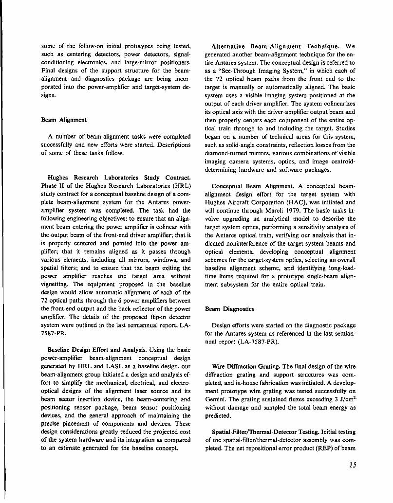
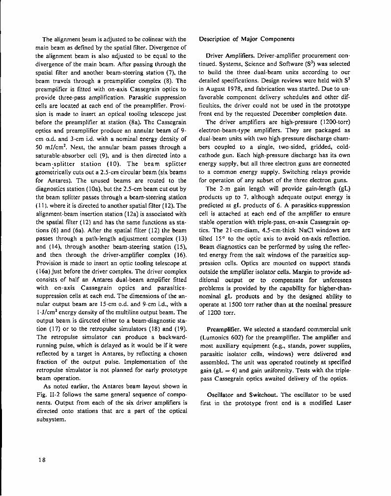
General Description of Beam Line and Arrangement of
Components
A schematic layout for the one-beam prototype is
shown in Fig. II-1. The Antares layout is shown in Fig.
II-2. The following description of the prototype beam
16

Fig. II-1.
Layout for one-beam Antares prototype front end.
L
s.
3,
A.
5.
&
7.
L
s
IQ
!L
12
51ABU O5CIUA1ORS
CSVJPP5RS
MISWAVJRS NM WASA CLMBIIKRPAT51W MJUSENS
PRSMP Omss 1A*1E
A.PkSS AOOSIIS P!AWAP ILIMWICS ~
*PASS AcQ5m PMAM? ILMONlcs m
SPATIAL FILM 81.Swmn W?.SPATIAL FILTER 62.MI-MM INJSC’WN SIAIICN
PmUP Imn omcs mmAU- SUSCOPt.SW s5SSRlffi 5TATIM,PRIW.W ussmum omcs
PARASITIC SUPPAt5SlC# OSLWKS
PNSMF -!C5 em
PSWSP CAnml LwTlcs TABLE.sIc~AKV CASSEC9AIN oMCS.BM SIIfRlffi STATISM
u.
1&
1$.
1A
11.
u
N.
A
SANWL5 A8SORBER cso.mm
Bum SPLITKR
SPAIIM ~lL1fR 43.ALIWWSST.BCAM INKCTIW STAIICN
PATN WGSSI ADJUS5SRS
DRIVER INPUT oPTICS 1A8LC.All- TSKW3PE.KM! STfSRINC SIATISN,PRIIMPX C4SSSGRAIN OPIKS
DRWSR NKPLlflsR
DRIVTN WIPUI LWllcs.SICmDARY CASWW!AIN oMCS.B~ SILINIW SIATlm.cslORIMslm
PM wwOsl STAIIIX
~ VACWM PI#A?
31. 5L.sclnm-cw PU5ES (532s?. PR5MP m SUPPLY
SS INSIRIMCWATICU PX?3
X 05 ClUAT08 DIAC?lOSTICS
3>. SCNISN ROMk mp urnB. Dlc VmIlftC FIKS OPTICS INKFSACSD. PDP IImL USMC mmf. SPARF MmC. FLOPPV DISKK OYAmlm TEFMINAL1. UARO COPY WITL 71MING MD C’OWWl~TIK RACKK DISPIAYS
36 TRANS1OSMSK
17, asAN nom CLLmlw, smw.s
5s Slla
Fig. II-2.
Layout of six-beam Antares front-end system.
line applies in all important respects to the Antares
system, with a sixfold duplication required in Antares af-
ter the beam splitter. In the following paragraphs, num-
bers in parentheses refer to numbers associated with
parts shown in Fig. II-1.
The beam, which originates in a multiline oscillator
(l), is sent through a spatial falter (2), a beam-steering
station (3), and a switchout station (4). At this point it
emerges from the oscillator complex as a multiline milli-
joules pulse of the desired duration (typically, 1 ns). The
spatial profile is Gaussian with a characteristic width
(l/e) of about 0.6 cm. The beam proceeds from the
switchout station to a beam-steering station (5), and then
through another spatial filter (6). An alignment-beam in-
sertion station (6a) is coupled to the spatial falter. Visible
or COZ alignment beams are inserted at this point.
17
The alignment beam is adjusted to be colinear with the
main beam as defined by the spatial filter. Divergence of
the alignment beam is also adjusted to be equal to the
divergence of the main beam. After passing through the
spatial filter and another beam-steering station (7), the
beam travels through a preamplifier complex (8). The
preamplifier is fitted with on-axis Cassegrain optics to
provide three-pass amplification. Parasitic suppression
cells are located at each end of the preamplifier. Provi-
sion is made to insert an optical tooling telescope just
before the preamplifier at station (8a). The Cassegrain
optics and preamplifier produce an annular beam of 9-
cm o.d. and 3-cm id. with a nominal energy density of
50 mJ/cm2. Next, the annular beam passes through a
saturable-absorber cell (9), and is then directed into a
beam jsplitter station (1 O). The beam splitter
geometrically cuts out a 2.5-cm circular beam (six beams
for Antares). The unused beams are routed to the
diagnostics station (10a), but the 2.5-cm beam cut out by
the beam splitter passes through a beam-steering station
(11 ). where it is directed to another spatial filter ( 12). The
alignment-beam insertion station ( 12a) is associated with
the spatial filter ( 12) and has the same functions as sta-
tions (6) and (6a). After the spatial filter ( 12) the beam
passes through a path-length adjustment complex (13)
and ( 14), through another beam-steering station (15),
and then through the driver-amplifier complex (16).
Provision is made to insert an optic tooling telescope at
( 16a) just before the driver complex. The driver complex
consists of half an Antares dual-beam amplifier fitted
with on-axis Cassegrain optics and parasitics-suppression cells at each end. The dimensions of the an-
nular output beam are 15-cm o.d. and 9-cm id., with a
1-J/cm2 energy density of the multiline output beam. The
output beam is dirtcted either to a beam-diagnostic sta-
tion (17) or to the retropulse simulators (18) and (19).
The retropulse simulator can produce a backward-
running pulse, which is delayed as it would be if it were
reflected by a target in Antares, by reflecting a chosen
fraction of the output pulse. Implementation of the
retropulse simulator is not planned for early prototype
beam operation.
As noted earlier, the Antares beam layout shown in
Fig. II-2 follows the same general sequence of compo-
nents. Output from each of the six driver amplifiers is
directed onto stations that are a part of the optical
subsystem.
Description of Major Components
Driver Amplifiers. Driver-amplifier procurement con-
tinued. Systems, Science and Software (S3) was selected
to build the three dual-beam units according to our
detailed specifications. Design reviews were held with S3
in August 1978, and fabrication was started. Due to un-
favorable component delivery schedules and other dif-
ficulties, the driver could not be used in the prototype
front end by the requested December completion date.
The driver amplifiers are high-pressure ( 1200-torr)
electron-beam-type amplifiers. They are packaged as
dual-beam units with two high-pressure discharge cham-
bers coupled to a single, two-sided, gridded, cold-
cathode gun. Each high-pressure discharge has its own
energy supply, but all three electron guns are connected
to a common energy supply. Switching relays provide
for operation of any subset of the three electron guns.
The 2-m gain length will provide gain-length (gL)
products up to 7. although adequate output energy is
predicted at gL products of 6. A parasitics-suppression
cell is attached at each end of the amplifier to ensure
stable operation with triple-pass, on-axis Cassegrain op-
tics. The 21 -cm-diam, 4.5-cm-thick NaCl windows are
tilted 150 to the optic axis to avoid on-axis reflection.
Beam diagnostics can be performed by using the reflec-
ted energy from the salt windows of the parasitic sup-
pression cells. Optics are mounted on support stands
outside the amplifler isolator cells. Margin to provide ad-
ditional output or to compensate for unforeseen
problems is provided by the capability for higher-than-
nominal gL products and by the designed ability to
operate at 1500 torr rather than at the nominal pressure
of 1200 torr.
Preamplifier. We selected a standard commercial unit
(Lumonics 602) for the preamplifier. The amplifier and
most auxiliary equipment (e.g., stands, power supplies,
parasitic isolator cells, windows) were delivered and
assembled. The unit was operated routinely at specified
gain (gL = 4) and gain uniformity. Tests with the triple-
pass Cassegrain optics awaited delivery of the optics.
Oscillator and Switchout. The oscillator to be used
first in the prototype front end is a modified Laser
18
Development Corporation (LDC) unit. The LDC os-
cillator combines a pulsed TEA laser of our design with
multiple low-pressure plasma tubes, one for each desired
line. The optical cavity for each line includes one low-
pressure plasma tube, but shares the TEA laser. A
grating combines the beams to give the unidirectional
multiline operation. The switchout is a standard LASL
design with three stages of CdTe Pockels cells and ger-
manium plate polarizers. The Pockels cells are driven by
a fast (nanosecond) high-voltage (25-kV) pulse generated
by a charged line and a spark-gap switch. All equipment
for the prototype oscillator-switchout system was
delivered, and checkout was begun.
Laser energy extraction calculations and predictions
of the performance of some target designs indicate the
need for pulse-shaping. In the LDC design, the common
beam volume in the TEA laser (part of the oscillator
cavity) produces coupling between lines and precludes
positive relative-line-amplitude adjustment. The Antares
oscillator design provides an extremely versatile system,
which allows positive amplitude control for each line as
well as pulse shaping by variable timing of pulses from
each line. The final switchout unit is identical to the
prototype unit and can, in principle, also provide pulse-
shaping by control of the switchout voltage pulse. The
Antares oscillator design uses six stable, 1-W, cw lasers,
each operating on a selected line. Each of the six beams
is switched out individually and directed through its own
path-length adjuster before being combined into a com-
mon beam path. Adjustment of the relative timing of the
pulses from different lines, either electrically or by path-
Iength difference, will produce pulse-shaping. Control
over the individual line amplitude further adds to the
line-shaping capability. Amplitudes can be adjusted by
varying the power input to the cw lasers and by inserting
attenuators. The 1-W power level in the cw lasers must
be amplified to 1 MW. The desired amplification is ac-
complished with four-pass amplification in a commer-
cially available laser (Lumonics K922S), which has a gL
product of 4. Amplification is performed after combining
the six beams into a single beam by combinations of
zinc-selenide beam splitters. No serious problems with
coupling between lines are expected because we are
operating the Lumonics laser in the small-signal regime
(output energy of 1 mJ vs available stored energy in
excess of 100 mJ). The four-pass amplification design
depends on a polarization rotator, germanium Brewster-
angle plates, and a Pockels-cell switch with germanium
plate polarizers. All four passes lie on a common path
that requires a minimum of gain volume. Good contrast
ratio is obtained because two passes are made through
the Pockels-cell switch. Design of the unit was completed
except for some detail drawings of minor parts. Parts
were ordered and fabrication was initiated.
The repetition rate for the Antares oscillator complex
can be as high as 3 Hz. Longer pulses, along with the
high repetition rate, will give output power useful for
some alignment tasks.
Beam-Line Components Not Associated Directly with
Amplifier. The spatial filters consist of two powered
mirrors with a pinhole of appropriate size located be-
tween them at the focal point of the input mirror. The
filters are used in the front end for spatial beam quality
control; beam-line definitions for use in alignment;
alteration of beam characteristics (size and divergence);
and retropulse interruption. The design of these units is
complete, and parts were either delivered or have been
ordered.
Beam-steering stations are used at various locations to
adjust beam position and direction, and to facilitate
positioning of the beam line relative to large units such
as amplifiers. These designs are complete, and parts were
delivered or have been ordered.
The saturable-absorber cell is included to enhance the
contrast ratio as needed. It is different from the
parasitics-suppression cells in that it needs to function
only on the selected lines of operation, whereas the
parasitic cells must cope with all lines that can produce
parasitic. The gas filling for the saturable absorber is
SF6. Design was completed and procurement started.
The beam splitter is a perforated mask whose holes
separate the number of needed beams. Appropriate op-
tics pick up these physically operated beams and direct
them as needed. Design was completed and parts have
been ordered.
The path-length adjuster compensates for the differing
locations of amplifiers (and hence, for the path length to
the target) by adding length to the shorter paths. Design
was completed and parts were ordered.
The alignment-beam insertion stations are similar to
those in Helios. The design was completed and parts
were ordered.
19

Controls and Diagnostics
The prototype front-end controls are identical to the
manual backup, checkout, and maintenance controls
designed for Antares. The manual controls are compati-
ble with switchover to computer control when com-
puters, interface hardware, and software become
available. Diagnostic or monitoring information from the
various components in the prototype front end is ob-
tained by Antares design sensors, signal generators, and
transmitters. The design incorporates fiber optics for
signal transmission wherever possible. The output of the
oscillator complex, the preamplifier, and the driver am-
plifier will be examined for total energy and for the tem-
poral and spatial character of the pulse.
Detailed lists specifying type and characteristics (e.g.,
voltage levels and impedance) of all Antares control and
monitor signals were prepared.
System Studies
Performance. Pulse energy and temporal charac-
teristics were calculated for the system. Our results in-
dicated acceptable performance, but uncertainties ex-
isted in the characterization of parasitic suppression by
saturable-absorber gases under the wide range of
operating conditions considered.
Gaussian-beam propagation calculations were made
to account for first-order diffraction effects. We ex-
amined beam stability and factored it into the design of
all components. The geometric magnification produced
by the Cassegrain optics used on the driver amplifier and
preamplifier desensitizes the system to directional
changes of the beam at the input end, but it enhances the
displacement sensitivity. All beam-line components are
mounted directly and rigidly to the building floor.
Whenever possible, mirror combinations are mounted in
such a way as to desensitize effects of their motion on
beam-line direction and position.
Reliability and Maintenance. Reliability received high
priority in all design work. We used conservative design
and specifications to achieve an expected misfire rate of
less than 1Vo.Maintenance for Antares was designed for
replacement of readily accessed components or groupsof components. Diagnostics were included for rapid
identification of the faulty replaceable part or group of
parts. Routine maintenance of energy storage units was
planned.
Safety. All components presenting electrical hazardswere designed with regard to personnel safety considera-
tions. Radiation hazards were addressed by controlled-
access procedures. Both the prototype front end and the
Antares front end were designed for a single controlled
access whenever radiation hazards are present. Special
handling equipment was designed or specified to
eliminate mechanical hazards to personnel.
Equipment is protected by hard-wired interlocks and
through computer check routines.
POWER-AMPLIFIER SYSTEM (R. Stine, R. Scarlett,
G. Ross, W. Turner, W. Miller, E. Yavornik, N. Wilson,
G. Allen, W. Gaskill)
The Antares power amplifier and a cross section are
shown in Figs. H-3 and -4. The unit is 16 m long, 3.7 m
in diameter, and the centerline is 3.2 m above the floor.
The basic design incorporates a centrally located 12-
sided grid-controlled cold-cathode electron gun, which
discharges radially into 4 annular pumping volumes.
Fig. II-3.A ntares power ampltjler.
Fig. II-4.
Cross section of Antares power amplljler.
20

All large long-lead-time components for the pressure-
vessel and electron-gun portions of the power amplifier
were ordered. The first electron gun, as well as the sup-
port stand for the first power amplifier, will be delivered
by July 1979. The pressure-vessel components will be
delivered soon thereafter for installation on the support
stand.
The first electron gun will be tested in Building 85, in-
dependent of the Laser Hall.
Pumping Chamber
Electrical Design and Testing. We designed and tested
a solid anode bushing using a compressed-rubber dielec-
tric. Initial voltage testing at 600 kV showed adequate
holdoff, but lifetime data were still required. A metal-
powder-loaded epoxy bushing was fabricated and
awaited testing. The backup position depended on the
water-graded bushing tested in the prototype power am-
plifier. The bushing holes in the pumping chamber were
enlarged to a diameter of 35 cm, to accept any of the
bushings under consideration. We completed a dielectric
divider design that is consistent with the revised electron-
gun support system. The dielectric divider is not an in-
tegral part of the support system, but it prevents ring-
mode optical parasitic and improves gain uniformity
and efficiency by containing the electron flux.
Mechanical. The pumping-chamber and spacer-spool
sections are being fabricated; delivery is expected in May
1979. The salt-window domes and back-reflector domes
were redesigned to eliminate costly forgings. These units
were ordered, and delivery is expected in September
1979. The design of the electron-gun support system was
nearly completed.
Electron Gun
Electrical Tests. Modifications were made to the
prototype power amplifier to allow in-depth testing of
electron-beam characteristics for the final Antares
design. The modifications included a new control-grid
design, improvements to the vacuum system, some ad-
ditional corona rings on the cathode assembly, viewing
ports in the grid, and a careful cleaning of all parts of the
electron gun. The major problem to be solved by these
modifications was grid emission at high voltages and at
grid resistance, which led to a loss of control of the
electron-beam current. In addition to the physical
modifications to the electron gun, we also developed a
grid-conditioning procedure, which consisted of shorting
the grid to the cathode and then operating the gun with a
series of pulses of increasing voltage. We tested these
changes in a series of runs at voltages between 300 and
500 kV and grid resistances between 250 and 1200 S2.
The improvements allowed operation at higher voltages
and grid resistances than previously possible, and there
was decreased frequency of grid emission at all voltages.
The results of these tests, which were incorporated into
the Antares electron-gun design, showed that the An-
tares electron gun should perform well within the re-
quired specifications.
We also conducted tests to determine the electrical
performance of the prototype dielectric dividers at low
voltage. When the electron-gun voltage was reduced to
300 kV, flashover was observed between the ribs of the
dividers. At 400 kV the flashover stopped. The new An-
tares designs for anodes and dielectric dividers were in-
stalled and will be tested.
We selected a test facility for the electron guns. Draw-
ings of building modifications required for the testing
program were submitted for approval. The modifications
included a pit for the vacuum system, lead shielding, and
a large screen room. We considered these provisions
necessary because of the late completion date for the
HEGLF laser building.
Mechanical. All four electron-gun weldments were
machined successfully. A typical weldment with the
machined hibachi slots is shown in Fig. II-5. The weld
Fig. II-5.
Typical electron-gun weldment with the machined
hibachi slots.
21

test program proceeded well, with all the flat samples
completed. Once the final ring sample is welded and
tested. the electron-gun section will be machined in
preparation for final welding and will be shipped to the
welding shop. We designed a revised sealing concept for
the junction of electron gun and pressure vessel. This
concept uses bellows and eliminates tight tolerances in
these large parts.
Three vacuum spools were being fabricated, with
delivery starting May 1979. Both the coaxial feed
bushing and the electron-gun support bushings were be-
ing fabricated, with delivery expected in April 1979.
Brazed-foil and glued-foil electron-gun windows were or-
dered for the first electron gun.
Gas and Vacuum Subsystem
The electron-gun high-vacuum turbomolecular pump
with its associated mechanical backing pumps was
received. We will install the system in an existing
building for electron-gun testing. Detail drawings of the
complete gas and vacuum system were started. The
Vacuum System Evaluation and Test Laboratory was
completed.
Handling Equipment
We emphasized the completion of the electron-gun
handling equipment because it is needed first. A low-boy
fixture. which will serve both as a handling fixture and a
test fixture for the electron-gun testing, was designed.
The fixture can be rotated to allow easy access to all 48
foil windows. Drawings for the grid/cathode assembly
fixture and for the 3.2-m-high gun-insertion fixture to be
used in the Laser Hall were completed.
Diagnostics
The design of the small-signal gain measurement
system was completed. We ordered the COZ laser as well
as all mirrors, mirror mounts, and other accessories.
This system will require a screen room in the Laser Hall,
which will be shared with the optical diagnostics.
A completely computer-integrated diagnostics system
was designed for the electron-gun testing.
Optical Support Structures
Detailed structural analyses of the back reflector,
relay optics, and in/out optics support structures were
completed. The drawing for the optical support structure
of the back reflector was completed; the relay and in/out
optical support-structure drawings will follow. The long-
Iead-time aluminum plate for these elements was or-
dered.
The optical components and their locations on the op-
tical support structures were defined. The first turning
mirror will have the same kinematic mount as the back
reflector and the periscope mirrors. The second turning
mirror and the focusing mirror will use a modified com-
mercial mirror mount. Prototypes of the trombone and
spatial filter were fabricated. A small mirror clamping
design was detailed, and mirrors were fabricated and
tested. The transmission gratings for large beam sampl-
ing were integrated into the optical support structures,
and three prototypes are being fabricated.
Support Stand
Weldment fabrication and final machining of the
power-amplifier support stand were ordered. The steel
box beams were ordered earlier and will be delivered to
the stand fabricator in mid-February 1979. The first sup-
port stand was scheduled to arrive by July 1979.
High-Voltage Cable
Both General Cable Company and Sieverts Kabelverk
dry-cured high-voltage cables were certified for use at
550 kV in the power amplifier. Specifications for bothcables were completed and sent out for bid.
Air Bearings
A new set of electron-gun air bearings was installed
and tested on the test vehicle during December 1978
(Fig. H-6). The new air bearings were a second-
generation version of the prototype bearings tested in
July 1978. The major difference between the prototype
and the new air bearings was the size of the internal air-
supply line, which was increased to 1.3-cm o.d. This
22

W --— –.-_––+–_
k.u!K mER (4 PIOCOS-C0 Ml,: cutar -LXl@JS dy) ,\~ . . ,,
..— — DIAPHRAGM;—
Fig. II-6.
Antares electron-gun air-bearing assembly (shown
inverted).
change was made to improve the performance of the air-
bearing assemblies. The smaller copper tubing on the
prototypes appeared to restrict the air flow to the bear-
ings, resulting in nonuniform lift and high frictional drag.
Our test results showed that the new air bearings had
more uniform lift, operated at a lower pressure, exhibited
a higher flow rate through the assembly, and required a
lower tow load than the prototype. These improvements
in performance were the direct result of increasing the
size of the air-supply line.
ENERGY STORAGE SYSTEM (K. Riepe, G. Allen, J.
Bickford)
The Energy Storage System supplies the high-power
high-voltage pulses to the gas discharges and electron
guns in the power amplifiers. The system consists of 24
gas pulsers storing 300 kJ each, and of 6 gun pulsers
that store 70 kJ each.
The gas pulsers will be built by a contractor. We built
a prototype gas pulser to provide information for evalua-
tion of proposals, to help us review the contractor’s
designs as they progress, and to provide a test bed for
controls and diagnostics.
Because requirements for the gun pulser have not been
fully defined, these pulsers will be designed and
fabricated in-house.
Gas Pulsers
Requests for quotation for 25 Marx generators (in-
cluding 1 spare) were sent to 4 vendors. Basic specifica-
tions were
Energy, kJ 300.Voltage. MV 1.2
Inductance, VH <3.0Jitter, rms, ns <20
Prefire Rate <0.01The contractor will be required to build one Marx in his
facility and to run it for 2000 shots to allow us to
evaluate its reliability. The first trigger system will be
tested for 50 000 shots. Bids were received from three
vendors. After some changes in specifications, best and
final offers were received in November 1978. Letter-
contract approval was predicted for late January 1979.
Testing of the prototype gas pulser was slowed by
failure of the charging-power supply. Because a power
supply of comparable size was not available, testing con-
tinued with a much smaller power supply.
The Marx generator was reconfigured to measure the
effect of spark-gap position on inductance. In the
original configuration, the spark gaps were placed away
from the centerline of the stage, toward the centerline of
the Marx. It was thought that this would minimize the
loop and, thus, the total inductance. However, we found
that moving the gaps back to the centerline of the stage,
and thus decreasing the stage inductance while increas-
ing the loop inductance, decreased the Marx inductance
from 2.7 to 2.4 vH.
New spark gaps, based on the spark-gap test
programs, were installed in the Marx. Before installation,
these gaps were tested to determine the effect of dimen-
sions and electrode condition on the self-breakdown
voltage (SBV) measured at atmospheric pressure with a
slight flow of air through the gap. The gap was isolated
from the power supply with a large ( 1-Mfl) resistor, and
a small capacitor (2.4 nF) was charged and discharged
through the gap. SBV was measured after several tens of
conditioning shots. The standard deviation of the 17
gaps tested was 1.8?40, and the largest difference was
3.4’70, indicating an acceptable tolerance stack-up.
The coated Carborundum resistors to be installed in
the gas-pulser prototype were received and tested before
installation. The test consisted of soaking the resistors in
oil for one week. The resistance increased if there werelarge holes in the coating. A 10-kJ, 10-kV capacitor was
then discharged through each resistor. When the resistor
was heated by the dissipated energy (10 kJ produced a
temperature rise of 50 K), a stream of small bubbles was
emitted from any pinhole leaks. About 20?10 of the
resistors failed this test. We continued to work on this
23

problem with Carborundum Corporation. They recom-
mended a double coating of polyurethane, rather than
the usual polyurethane-over-epoxy coating.
Electron-Gun Pulser
The electron-gun pulsers provide the energy to drive
the electron guns. The beams from the electron guns
control the ionization density, hence the impedance, of
the gas discharges. The gun current density controls the
overall impedance, whereas the voltage controls the elec-
tron range, and thereby controls the gain distribution.
We conducted a theoretical and experimental program
to determine the optimum voltage and waveform.
If the optimum waveform is square or trapezoidal, a
Guillemin network can be used. We built and tested to
full voltage a megavolt, two-mesh, type-A Guillemin-
Marx generator. In addition, we used the Marx portion
of the network to life-test the high-voltage cable samples.
This procedure provided a good life-test of the Marx it-
self. The disadvantage of the Guillemin network was that
it limited the risetime. Experiments indicated that a
voltage rise of several kilovolts per nanosecond was re-
quired for uniform ignition of the cathode. Thus, the
Guillemin network required a peaking capacitor and
switch to provide this voltage rise.
Theory indicated that the optimum gun waveform was
a high-voltage spike (500-600 kV), followed by a lower
voltage plateau (300-400 kV). The high-voltage spike oc-
curred before voltage was applied to the gas, fully ioniz-
ing the entire volume. After voltage was applied to the
gas, the applied electric field allowed the use of lower
energy electrons, while maintaining ionization across the
full discharge gap. We found experimentally that,
without the initial high-voltage spike, gas breakdown oc-
curred. This waveform can be generated by a Guillemin
network. However, a good approximation may also be
generated by a straight Marx generator, which has the
advantage that it may be built with low inductance, and
thus does not require a peaking circuit to provide good
ignition of the electron gun. These considerations led to
the selection of a simple inexpensive Marx generator as
the Antares gun pulser.
Component Development
After completion of the spark-gap life-testing under
fault conditions, we performed some experiments to
characterize the gap under normal operating conditions.
A dummy load was inserted in series with the spark gap
to limit the peak current to -250 kA with 25?40reversal.
The parameters of interest were trigger jitter and prefire
rate.
It is difficult to relate spark-gap jitter to Marx jitter
because the Marx jitter depends on the internal coupling
of the Marx. However, if the spark-gap jitter is high, the
Marx jitter will obviously also be high. Switch jitter was
less than 10 ns with a 200-kV trigger pulse at 120 kV
and at a safety factor of 2. This implied that a trigger
pulse of more than 200 kV, and probably at least 300
kV, will be needed for the Marx to achieve a Marx jitter
of <20 ns.
To achieve the specified Marx prefire rate of about 1
in 100, the individual spark-gap prefire rate should be
less than 1 in 2500. Verification of this value would take
more than 5000 shots. This was not considered
reasonable, and a less direct approach was taken. The
distribution of SBV at a pressure corresponding to a
mean SBV near 100 kV was measured, and the
probability of self-breakdown at or below one-half the
mean SBV was calculated by assuming that the distribu-
tion was Gaussian, and that the standard deviation was
independent of pressure. The standard deviation of SBV
was between 2 and 3940of SBV over the range of 50 to
120 kV. If the distribution is Gaussian, then the prefire
probability y at one-half SBV is negligible (< 10-lOO).From
experience, we know that the pretlre rate will be higher,
so either or both assumptions were incorrect. However,
the standard deviation of gaps operating at much lower
current is also on the order of 2 to 3°h, so we may expect
that the prefire rate of the Antares gaps will be no worse
than that of conventional gaps.
Power Supplies
Specifications for the Antares power supplies were
written. We require a gas-pulser power supply that will
charge four gas pulsers in one minute. Six will be re-
quired. The gun-pulser power supplies will charge one
gun pulser in -20 s, depending on the gun-pulser energy.
Six will be required. One spare of each will be purchased.
The first unit of each power supply will be required to
undergo a proof-of-design performance test at the
manufacturer’s facility, as follows.
a. Operate high-voltage transformers without rec-
tifiers at 200V0 of rated voltage for 7200 cycles.
24

b. Short the output through a 100-ft-long cable at 60-
kV charge with a vacuum relay.
c. Operate the full power supply into an open circuit
at 130?40of maximum charge voltage (78 kV) or at max-
imum open-circuit voltage, whichever is higher, for 6
hours.
d. Operate with both polarities short-circuited for 1
hour:
e. Operate at full power into a resistive load for 1
hour.
We expect these tests to guarantee the reliability of the
power supplies. Each power supply will be required to
pass an acceptance test consisting of the transformer test
at 200?40of rated voltage, and of 2-hour open- and short-
circuit tests.
and of three short beam tubes. This position will be used
primarily for initial installation and major overhaul of
the 12 mirror arrays. For normal operation the target
chamber will remain closed; targets and diagnostic
equipment will be changed by means of air locks without
breaking vacuum; and minor maintenance will be carried
out by backfilling the target vacuum system with air and
entering through a man-access hatch.
Activity related to the target system was markedly in-
creased, which made it appropriate to organize a more
formal target system team, made up of the regular con-
tributors from the various design disciplines, primarily
from L-Division’s Antares Group, and of representatives
from the Target Diagnostic and Target Fabrication
Groups. Brief weekly coordination meetings were
valuable for spotting action items and for keeping the ef-
fort on schedule.
TARGET SYSTEM (P. Wolfe, J. Allen, W. Sweatt, N.
Wilson, V. Zeigner)Optical Train
Introduction
The scope of the target system is illustrated in Fig. II-
7, an artist’s sketch of the target vacuum system. Six
beam tubes, each 1.7 m in diameter and -35 m long, ex-
tend underground from the north wall of the Laser Hall
to the Target Building, where they connect to six 3-m-
diam turning-mirror chambers. Six smaller beam tubes
lead to a centrally located target chamber, a 7-m-diam
vessel that houses a space frame, which, in turn, carries
arrays of folding and focusing mirrors for each beam, as
well as a precision target-insertion mechanism. Figure II-
7 shows the space frame in its rolled-out position, which
requires the removal of one target-chamber end dome
—— TARGtXCHAMGESANOVACUUMSYSTEM—-
-._~. -- - _ .!
-- ..- c-.-. —
Fig. II-7.A rtist’s sketch of Antares target vacuum system.
As described in some detail in the previous semian-
nual progress report (LA-7587 -PR), the portion of the
optical system within the target chamber was radically
redesigned to decrease the focal length of the focus
mirrors that illuminate the target. Although this change
had the desired effect of decreasing the spot size on
target, it made the layout of components in the space
frame and the use of space near the target for experi-
ments much more critical. In addition, it increased the
diversity of required sector mirror shapes over that of
the earlier, more symmetric design. Therefore, we con-
ducted several detailed studies of outline ray trajectories
between mirrors and of beam footprints on mirrors and
mirror arrays before completing the design. An indepen-
dent check of the representative results of our in-house
calculations was performed on the Antares optical train
as a part of the Hughes Aircraft study contract.
Target Positioner
This component of the target system might be
described more properly as a target insertion and preci-
sion positioning mechanism. As a key element in the op-
tical train, its design must satisfy not only obvious
functional requirements, but also must provide forreproducibly locating targets within a few tens of
25

micrometers of a fixed point in space, and for accom-
modating optical alignment tooling to ensure that the
remainder of the optical train is aligned and focused on
that point. In addition, for cryogenic targets, the
positioner must incorporate retractable means for cool-
ing the target up to a few milliseconds before shot time.
On the basis of the successful design developed for the
Helios system we commissioned the same LASL group
to develop a successor for use on Antares. A design and
development schedule consistent with the overall target
system schedule was worked out, and design work
began, with first tasks consisting of firming the require-
ments for precise target positioning and for interfaces of
the alignment system.
Space Frame
Upon completion of interference checks for the
revised optical layout within the target chamber, we
reinitiated the design effort on the space frame. The
general frame envelope of this structure was already
fairly well defined, because it had to be established to
permit the design of the target chamber to proceed (see
Target Vacuum System, below). The remaining structure
consists of 12 supplementary frames to hold the 6
folding-mirror arrays and the 6 focusing-mirror arrays,
plus members to provide rigidity. We could not use a
common design for the supplementary support frames;
this added complexity to the task of designing and
analyzing the overall space frame. Overlying the integra-
tion of these members into an overall structure were the
requirements that no optical-beam interferences be in-
troduced, and that adequate target access be provided
for fusion experiments.
Two design layouts were generated and supplemen-
tary scale models were built. These models permitted a
critique of structural-member placement from the
standpoint of the frame’s probable rigidity; provided
clear insight on interferences and accesses; and served as
indispensable aids in setting up the necessary
mathematical models of the overall structure for rigidity
and vibration analyses. At the end of 1978, we selected
one design and initiated mechanical analyses.
Target Vacuum System
This part of the target system composes the entire
vacuum envelope, as shown in Fig. II-7 and described in
the introduction to Sec. 11.F, together with the pumps
and controls needed to rough and maintain an operating
pressure of 2 x 10⁻⁶ torr in the target chamber. In
August 1978, we awarded a contract to design and build
this system to the Pittsburgh-Des Moines Steel Com-
pany (PDM), and a meeting of PDM and LASL design
groups was held at LASL.
At the end of a 10-week conceptual design effort by
PDM. a 3-day preliminary design review was held in
Pittsburgh. Structural concepts presented by PDM were
accepted with minor revisions, such as providing access
stairs instead of ladders, and aluminum platforms rather
than steel. However, acceptance of the high-vacuum-
system design was delayed, pending further calculations
and verification of pumping capabilities and com-
patibilities of the proposed combination of Freon-chilled
baffles to handle water vapor, and helium-refrigerated
surfaces to pump other gases.
A review of a revised pumping scheme was held in
December 1978, but some apprehensions remained, and
an alternative design based on helium-refrigerated
pumps alone was requested by LASL. Our experience
with this approach on Helios led us to believe it to be
reliable and adequate; to our knowledge, the combina-
tion system has never been tried on applications like
ours. PDM accepted our recommendation.
In December, authorization was given PDM to initiate
procurement of certain long-lead-time items and
materials. A final design review was scheduled for
March 1979, before beginning fabrication.
CONTROLS SYSTEM (M. Thuot, D. Call, D. Carsten-
sen, D. Gutscher, A. Kozubal, R. Lindberg, F. Maestas,
F. McGirt, W. Seifert, B. Strait)
General
Final requirements for the Antares Controls System
were established. These requirements are listed below.
Absolute Requirements
. Accept and execute operator commands according
to predetermined algorithms.● Prepare and fire the laser in a specified sequence.
● Acquire, store, and display laser and control system
information.
● Meet the schedule determined by the installation
and checkout of other Antares subsystems.
Design constraints that tend to limit the manner in
which absolute requirements are met are listed below,
26
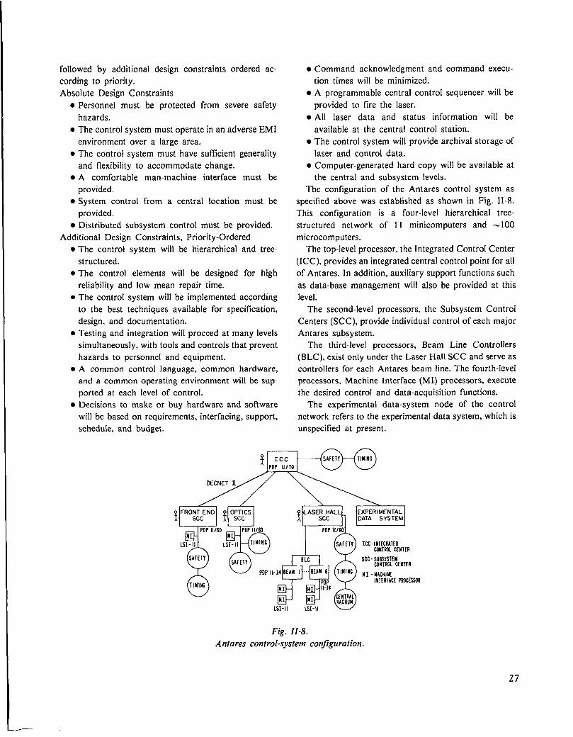
followed by additional design constraints ordered ac-
cording to priority.
Absolute Design Constraints● Personnel must be protected from severe safety
hazards.
● The control system must operate in an adverse EMI
environment over a large area.● The control system must have suftlcient generality
and flexibility to accommodate change.● A comfortable man-machine interface must be
provided.● System control from a central location must be
provided.● Distributed subsystem control must be provided.
Additional Design Constraints, Priority-Ordered● The control system will be hierarchical and tree-
structured.● The control e]ements will be designed for high
reliability and low mean repair time.
● The control system will be implemented according
to the best techniques available for specification,
design, and documentation.
● Testing and integration will proceed at many levels
simultaneously, with tools and controls that prevent
hazards to personnel and equipment.● A common control language, common hardware,
and a common operating environment will be sup-
ported at each level of control.
● Decisions to make or buy hardware and software
will be based on requirements, interfacing, support,
schedule, and budget.
● Command acknowledgment and command execu-
tion times will be minimized.● A programmable central control sequencer will be
provided to fire the laser.
● All laser data and status information will be
available at the central control station.● The control system will provide archival storage of
laser and control data.● Computer-generated hard copy will be available at
the central and subsystem levels.
The configuration of the Antares control system as
specified above was established as shown in Fig. II-8.
This configuration is a four-level hierarchical tree-
structured network of 11 minicomputers and -100
microcomputers.
The top-level processor, the Integrated Control Center
(ICC). provides an integrated central control point for all
of Antares. In addition, auxiliary support functions such
as data-base management will also be provided at this
level.
The second-level processors, the Subsystem Control
Centers (SCC), provide individual control of each major
Antares subsystem.
The third-level processors, Beam Line Controllers
(BLC). exist only under the Laser Hall SCC and serve as
controllers for each Antares beam line. The fourth-level
processors, Machine Interface (MI) processors, execute
the desired control and data-acquisition functions.
The experimental data-system node of the control
network refers to the experimental data system, which is
unspecified at present.
. ~n
DECNET II
yy% ‘ ‘“S’l[:ETY=ER
QBLC SCC-SUBSYSTEM
yuCONTROLCENTER
POPIk34BEAHI -. B[AH6 ‘l”’NC HI-MACHINElNTERfACEPROCIWI
($AFETY)a(TIUINC) m T cm’!, ‘
3 w’-@LSI-11 1s1-11
Fig. II-8.
Antares control-system configuration.
27

Communication facilities between all network nodes
will be supplied by a commercially available package.
Hardware
After competitive bidding, computer hardware was
selected as shown in Fig. II-8 with Digital Equipment
Corporation (DEC) supplying all the computers and
communication facilities. The network hardware will be
ordered in stages. The first stage, obligated from FY-79
funds, includes the ICC processor; the three SCC
processors for the front end, laser hall, and optics
systems; and two third-level processors. The remaining
five third-level processors for beam-line control will be
procured from FY-80 and FY-81 funds.
The configuration of the machine interface processor
(MI) has not been finally determined. Work is in
progress to establish the control and data-acquisition in-
terfaces to be supported.
~FTWXRf HliRARCHY CHART - CONIROLS‘SVSTfM
=-- OPERATC SYSTEM
i&mmk!!~-. .
Fig. II-IO.
Antares software hierarchy chart of the lower level
modules (Operate System).
ANTARES SOFTWAR[ HIERARCHY CHART - CONTROLS SYSTEM
2. MANAGE DATA
Software
Schedule and budget required that as much of the An-
tares software be purchased as possible. This par-
ticularly applied to operating systems, communications
support, and even to the use of device drivers, where ap-
propriate. Only in the case of specialized applications
tasks or when vendor-supplied software is not available
will we write our own software.
Design and implementation of these application tasks
began with the definition of software modules. The first
or top-level modules for the Antares software are shown
as a hierarchy chart in Fig. II-9, which only describes
the major software functions and the interrelationships
between these functions. The data paths are not
described. Lower level modules are shown in Figs. 11-10
to 11-12.
———. .-
Fig. II-I 1.
Antares software hierarchy chart of the lower level
modules (Manage Data).
ANTARES SOFTWARE NIERAiiCliY CHART - CONTROLS SYSTfAl
3. MANACE COMMANOS
-.—.
Fig. II-12.
Antares software hierarchy chart of the lower level
modules (Manage Commands).
Fig. II-9.
A ntares soft ware hierarchy chart.
28
Front-End Controls Antares Timing System
Detailed control requirements, complete with cost and
manpower estimates and schedules, were integrated into
the total control-system effort, which contributed to final
definition of the overall control structure described
above. Tests of hardware in several areas such as
CA MAC crate controllers for the LSI-I 1
microprocessors were completed. A specification was
written for the standard Antares crate controller.
Laser Hall Controls
Detailed control requirements specified by System
Managers for the power amplifiers, electron-gun test,
laser diagnostics, and energy storage were integrated
into the overall control-system effort. Interactions with
other systems were also specified. This work contributed
to the establishment of the controls-system architecture
and general approach.
Beam Alignment
Hardware designs for stepping-motor controls, hand-
held controllers, and sensor electronics were completed.
Network Management
Most of our effort was expended for site preparation
and procurement of computer hardware. In addition,
plans for computer relocation in the Antares central-
control screen room and installation of DECNET H be-
tween a PDP 11/60 processor and an LSI- 11 processor
were completed.
Requirements for the Antares timing system were
specified. These requirements will be used to write a
specification before design, implementation, and
procurement of the timing system.
ICC and Central Control
Requirements for the operator-machine interfaces for
Antares are being established, including specifying
operator control and status displays, video and audio
signals, control panels, and terminals. In addition, a
large amount of time was spent in specifying the data
archival system for Antares.
341 Configuration
A team was formed to establish the MI configuration
required for Antares control. Work was started on an
evaluation of the input/output interfaces, the fiber-optic
packaging, and an EMI enclosure specification.
Antares Software
A team was formed to implement the Antares produc-
tion software using structured programming methods.
Work on the top-level modules was begun.
Early Support
A team was formed to provide early temporary sup-
port for data-acquisition and control activities in the
following areas.
29

● )3ectron-gun test facility
● Small-signal gain measurement development
● optical systems development
● Laser diagnostics
● Front-end systems development
Work has begun to establish a general package for the
parallel 1/0 interface driver for PDP 11/03 computers.
HEGLF SITE AND STRUCTURES (J. Allen)
Construction Package I
As of December 31, 1978, the job was 48V0 complete
with 74% of the time consumed. This meant a reschedul-
ing of the completion date from mid-July to late Septem-
ber 1979. The delay was caused by abnormally bad
weather, change orders, bad concrete samples, and im-
proper planning by the Contractor. Figure II-13 is an
aerial view of the site, taken in late summer 1978. The
status of the elements that make up Package I is outlined
below.
Laser Building. The high-bay portion of the laser
building, which houses the power amplifiers and energy-
storage equipment, is shown in Fig. 11-14. According to
the construction sequence chosen by the Contractor, this
part of the package will be completed later than most of
the other elements. Power-amplifier installation in this
area is to start by early August 1979. A joint-occupancy
Fig. 11-13.
Aerial view of HEGLF site.
m mimwmti
Fig. II-14.
High-bay portion of laser building
power ampltjiers and energy-storage
housing the
equipment.
arrangement must be worked out between LASL and the
Contractor if this schedule is to be maintained.
Most of the wall panels were erected and a portion of
the support slab for the power amplifiers was poured. A
fortunate selection of a low-profile crane allowed us to
gain 2 ft of hook height with only a minor change to the
column design.
The office, laboratory, and shop portions of the laser
building have progressed farther than the high bay, with
grade beams poured and the T-beam roofing sections in-
stalled over two-thirds of this area. All underground con-
duit and piping were installed.
The front-end room received one coat of paint and the
air-conditioning ducting was installed.
Mechanical Building. The floors, equipment pads,
walls. and roof concrete work were completed. The
mechanical building and the laser-building shops and
laboratory areas were completed first to accommodate
the mechanical and electrical subcontractors’ work.
water chillers, boilers, an air conditioner, and some pip-
ing were installed. Part of the tritium stack was erected.
OffIce Building. The walls and T-beam roof sections
were installed. The underground conduit and piping were
installed. Some concrete test specimens taken from the
T-beam pours had low 28-day break values, but ad-
ditional cores taken from the T beams later, showed ade-
quate concrete strength. Of?ice and laser-building con-
struction was delayed until the discrepancy was re-
solved.
30
Warehouse. A prefabricated design that satisfied
everybody was selected. Construction will start when the
ground thaws –probably in April 1979.
Package II
The north and west walls of the target building were
completed. The south wall was two-thirds complete, with
the beam-tube penetration inserts in place. The scaf-
folding to support the forms for the 5-ft-thick roof was in
place. This building should be finished in July 1979,
which is compatible with the scheduled start date of
August 1. 1979 for target vacuum system installation.
This package was 42% complete with 76% of the time
consumed.
The 500 000-gal. water tank and the backup fire
protection system were nearly complete. The tank was
not painted. pending resolution of safety procedures to
be used by the Contractor.
The rebuilding of the power line leading into the site to
accommodate the extra HEGLF load was completed.
High-Voltage and Optical Evaluation Laboratories
Both laboratories were essentially complete. The
laboratories were scheduled for occupancy in mid-
January 1979. The original contract completion date of
October 23, 1978 was missed because of late delivery of
the boiler and hot-water pumps. Several design deficien-
cies became apparent during the final walk-through and
contributed to the delay.
31

III. C02 LASER TECHNOLOGY
(J. F. Figueira)
Each of our COZ laser systems described earlier represents a significant advance in
the state of the art of reliable COZ laser subsystems, components, and diagnostics. The
design, construction, and improvement of the systems require, therefore, basic support
of COZ technology. Some important areas are the development of short-pulse multifre-
quency oscillators; amplifier optimization; development of subsystems for the preven-
tion of system self-oscillation and removal of prepulse energy, including the study of
relaxation processes in bleachable gases; and the development of passive means to
enhance laser beam quality and simultaneously to provide automatic target alignment
through phase conjugation.
PROPAGATION STUDIES (S. J. Czuchlewski, J. F.
Figueira, A. V. Nowak, E. J. McLellan, C. E. Knapp)
Introduction
We evaluated the performance of a 1O-GW sub-
nanosecond COZ laser system prototype capable of
reliably generating pulses of good optical quality and
high peak irradiance at a repetition rate of 0.1 Hz. This
system will be used to conduct development studies in
support of our COZ Laser Fusion program, including
target diagnostics development, optical damage
threshold studies, the evaluation of gaseous and solid-
state saturable-absorber isolators, and the development
of phase-conjugate reflectors. Comparisons were made
between the energy and pulse shapes obtained with this
system and those predicted by a theoretical model that
has been used extensively in high-power COZ amplifier
design. In this case, the model is examined in a regime
where the input pulse width is less than half the effective
rotational relaxation time, a domain in which it has not
previously been tested.
Apparatus
The prototype consisted of a reinfection COZ os-
cillator, an electro-optic switch system for producing
subnanosecond pulses, and a power amplifier (Fig. III-
1). A commercial TEA laser was used as the power am-
plifier. Both the oscillator and the power amplifier were
multipassed to optimize system performance.
The oscillator and electro-optic switch were described
previously.’ The Lumonics-600A TEA power amplifier
OUT
IN
\ I. \It+
ICUT
OS CIAMP\ !
J \ ,1 SMOOTHING
/ 1 TUBE
rI 1 n.
i —’)
A wL=I.8 ~
Ioc 1
/\ 3-STAGE \02 —10ns E-O SWITCH, ~70 -ns pulse
Fig. III-1.Two-stage TEA laser system, showing the reinfec-
tion oscillator, the electro-optic switch, and the
triple-passed Lumonics power amp[ljler.
is a double-discharge, uv-preionized device with an ac-
tive volume of 8.9 by 10 by 50 cm,z capable of operating
at a repetition rate of 0.1 Hz. The gas mix used was
61: 15:24 ::He: Nz:COz at 580 torr. Small-signal gain was
4Vo/cm, measured with an attenuated multiline, gain-
switched pulse that sampled a 25-cm2 cross section of
32
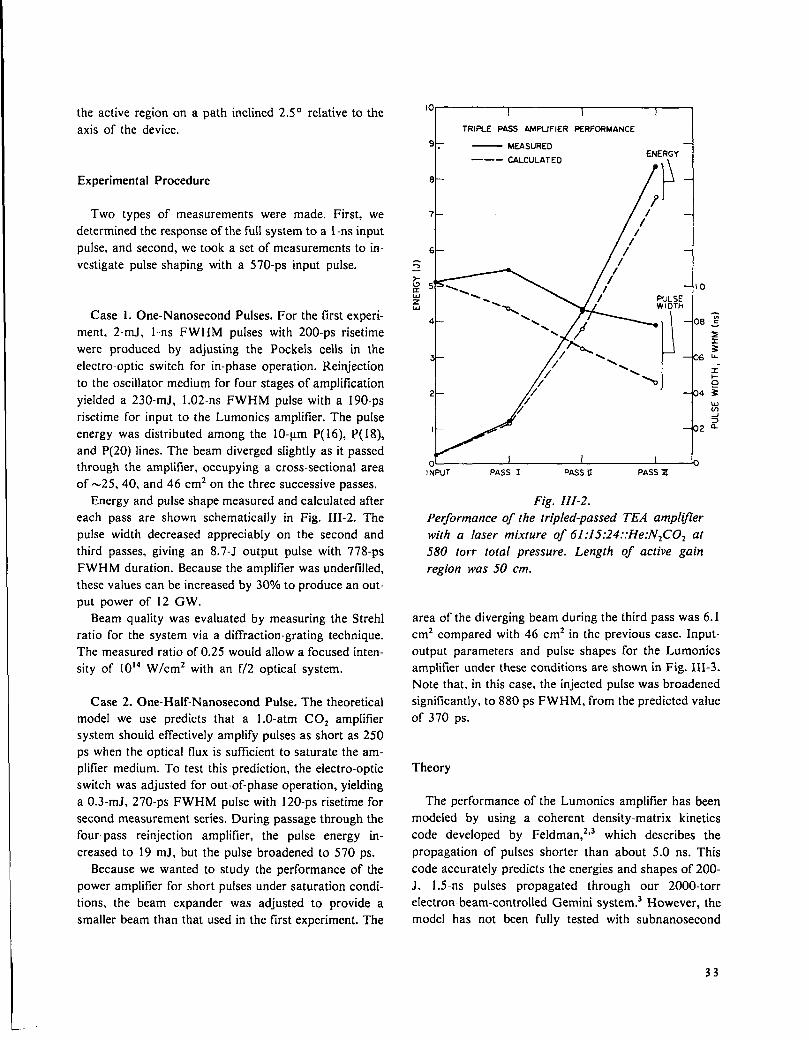
the active region on a path inclined 2.50 relative to the
axis of the device.
Experimental Procedure
Two types of measurements were made. First, we
determined the response of the full system to a 1-ns input
pulse. and second, we took a set of measurements to in-
vestigate pulse shaping with a 570-ps input pulse,
Case 1. One-Nanosecond Pulses. For the first experi-
ment. 2-mJ, 1-ns F WHM pulses with 200-ps risetime
were produced by adjusting the Pockels cells in the
electro-optic switch for in-phase operation. Reinfection
to the oscillator medium for four stages of amplification
yielded a 230-mJ, 1.02-ns FWHM pulse with a 190-ps
risetime for input to the Lumonics amplifier. The pulse
energy was distributed among the 10-~m P( 16), P( 18),
and P(20) lines. The beam diverged slightly as it passed
through the amplifier, occupying a cross-sectional area
of -25, 40, and 46 cmz on the three successive passes.
Energy and pulse shape measured and calculated after
each pass are shown schematically in Fig. 111-2, The
pulse width decreased appreciably on the second and
third passes, giving an 8.7-J output pulse with 778-ps
FWHM duration. Because the amplifier was underfilled,
these values can be increased by 30°/0 to produce an out-
put power of 12 Gw.
Beam quality was evaluated by measuring the Strehl
ratio for the system via a diffraction-grating technique.
The measured ratio of 0.25 would allow a focused inten-
sit y of 10*4 W/cmz with an f/2 optical system.
Case 2. One-Half-Nanosecond Pulse. The theoretical
model we use predicts that a 1.O-atm COZ amplifier
system should effectively amplify pulses as short as 250
ps when the optical flux is suftlcient to saturate the am-
plitier medium. To test this prediction, the electro-optic
switch was adjusted for out-of-phase operation, yielding
a 0.3-mJ, 270-ps FWHM pulse with 120-ps risetime for
second measurement series. During passage through the
four-pass reinfection amplifier, the pulse energy in-
creased to 19 mJ, but the pulse broadened to 570 ps.
Because we wanted to study the performance of the
power amplifier for short pulses under saturation condi-
tions, the beam expander was adjusted to provide a
smaller beam than that used in the first experiment. The
t
TRIPl_E PASS AMPLIFIER PERFmMANCE
9. — MEASURED
—— - CALCULATEDENERGY
●l\ i
‘t-7
6 I
1NPUT PASS I PASSu PASSIll
Fig. III-2.
Performance of the tripled-passed TEA ampltjler
with a laser mixture of 61 :15:24 ::He:NzCOz at
580 torr total pressure. Length of active gain
region was 50 cm.
area of the diverging beam during the third pass was 6.1
cm2 compared with 46 cm2 in the previous case. Input-
output parameters and pulse shapes for the Lumonics
amplifier under these conditions are shown in Fig. III-3.
Note that, in this case, the injected pulse was broadened
significantly, to 880 ps FWHM, from the predicted value
of 370 ps.
Theory
The performance of the Lumonics amplifier has been
modeled by using a coherent density-matrix kinetics
code developed by Feldman,2’3 which describes the
propagation of pulses shorter than about 5.0 ns. This
code accurately predicts the energies and shapes of 200-
J. 1.5-ns pulses propagated through our 2000 -torr
e[ectron-beam-controlled Gemini system.3 However, the
model has not been fully tested with subnanosecond
33
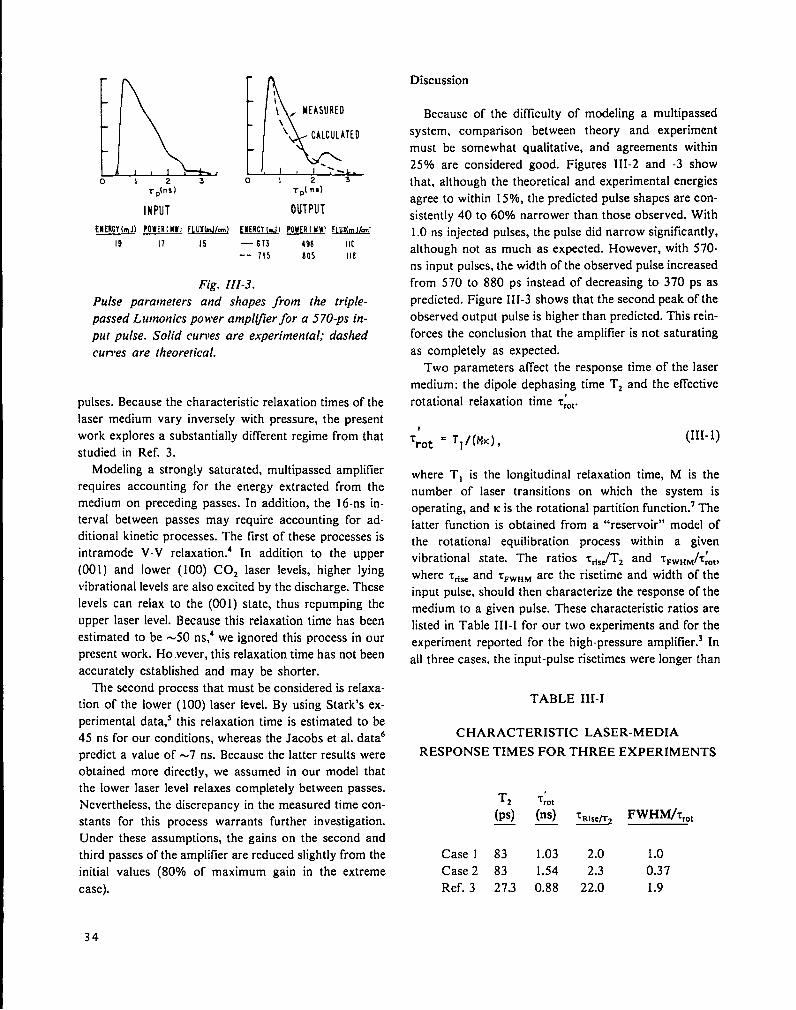
ko 1 2 3
Tp(nsl
INPUT
l’)%..\I\ , MEASURED\\ CALCULATED
‘.-o 2 3
Tp( nt.)
OUTPUT
[MERCY[m.J) POWER[ MU; FIUXW/cm) EIIERCY(TJ1POWIR( MW’ WX(mJ/ar:
19 11 Is —673 498 Ilc-- 715 $05 11P,
Fig. III-3.
Pulse paratneters and shapes from the triple-
passed Lutnonics power ampll~erfor a 570-ps in-
put pulse. Solid curves are experimental; dashed
curres are theoretical.
pulses. Because the characteristic relaxation times of the
laser medium vary inversely with pressure, the present
work explores a substantially different regime from that
studied in Ref. 3.
Modeling a strongly saturated, multipassed amplifier
requires accounting for the energy extracted from the
medium on preceding passes. In addition, the 16-ns in-
terval between passes may require accounting for ad-
ditional kinetic processes. The first of these processes is
intramode V-V relaxation.’ In addition to the upper
(00 1) and lower (100) CO, laser levels, higher lying
vibrational levels are also excited by the discharge. These
levels can relax to the (001) state, thus repumping the
upper laser level. Because this relaxation time has been
estimated to be -50 ns,’ we ignored this process in our
present work. Ho .vever, this relaxation time has not been
accurately established and may be shorter.
The second process that must be considered is relaxa-
tion of the lower (100) laser level. By using Stark’s ex-
perimental data,s this relaxation time is estimated to be
45 ns for our conditions, whereas the Jacobs et al. dataG
predict a value of -7 ns. Because the latter results were
obtained more directly, we assumed in our model that
the lower laser level relaxes completely between passes.
Nevertheless, the discrepancy in the measured time con-
stants for this process warrants further investigation.
Under these assumptions, the gains on the second and
third passes of the amplifier are reduced slightly from the
initial values (80V0 of maximum gain in the extreme
case).
Discussion
Because of the difficulty of modeling a multipassed
system, comparison between theory and experiment
must be somewhat qualitative, and agreements within
25?40 are considered good. Figures III-2 and -3 show
that, although the theoretical and experimental energies
agree to within 15%, the predicted pulse shapes are con-
sistently 40 to 60?40narrower than those observed. With
1.O-ns injected pulses, the pulse did narrow significantly,
although not as much as expected. However, with 570-
ns input pulses, the width of the observed pulse increased
from 570 to 880 ps instead of decreasing to 370 ps as
predicted. Figure III-3 shows that the second peak of the
observed output pulse is higher than predicted. This rein-
forces the conclusion that the amplifier is not saturating
as completely as expected.
Two parameters affect the response time of the laser
medium: the dipole dephasing time Tz and the effective
rotational relaxation time ~~Ot.
1
‘rot = T1/(MK) ,(111-1)
where T, is the longitudinal relaxation time, M is the
number of laser transitions on which the system is
operating, and K is the rotational partition function.’ The
latter function is obtained from a “reservoir” model of
the rotational equilibration process within a given. .
1’wbratlonal state. The ratios ~ti~~Tz and ~~~”~ 7rOt,
where Tn,, and TFWHM are the risetime and width of the
input pulse, should then characterize the response of the
medium to a given pulse. These characteristic ratios are
listed in Table III-I for our two experiments and for the
experiment reported for the high-pressure amplifler.3 In
all three cases. the input-pulse risetimes were longer than
TABLE 111-1
CHARACTERISTIC LASER-MEDIA
RESPONSE TIMES FOR THREE EXPERIMENTS
Case 1 83 1.03 2.0 1.0
Case 2 83 1.54 2.3 0.37
Ref. 3 273 0.88 22.0 1.9
34

Tz, and the risetimes should not have been degraded by sitive liquid-helium-cooled Hg:Ge detector; the 10-cm
the amplifiers, which agrees with the experimental data. gas cell in which the two laser beams cross was replaced
For Case 2, however, the pulse width equals 0.4 T~Ot, by a 3.1 -cm. cell tilted -45° with respect to the beams;
which may explain why the pulse broadened as it and a germanium polarizer stack was placed in the
traveled through the amplifier. The reservoir model used monitor beam between the double-resonance cell and the
in the computer code has not been tested in this regime Hg :Ge detector to reduce the intensity of unwanted scat-
(especially for multiline pulses), which could explain the tered light.
apparent discrepancy with theory.
Results and Discussion
Conclusions
The performance of a highly reliable, relatively simple
and compact, 1O-GW, subnanosecond COZ laser system
has been demonstrated successfully. Results suggest that
the 1.O-atm TEA amplifier is not effective at propagating
pulses shorter than -780 ps. Our experimental results do
not agree with calculations of short-pulse propagation.
This discrepancy has not been resolved. Further ex-
perimental work is under way to study the propagation
of intense subnanosecond pulses during a single pass of
the Lumonics amplifier, when the process has not been
complicated by multipass phenomena. A new high-
-pressure (2000—8000 torr) double-discharge reinfection
oscillator is being installed to facilitate this investigation.
The present study has also demonstrated the need for
more detailed measurements on the kinetics of C02 laser
media for pulse durations >10 ns, to determine the ef-
fects of repumping by intramode V-V processes.
SATURABLE - ABSORBER RECOVERY (A. V.
Nowak)
Introduction
An earlier reports described double-resonance experi-
ments designed to measure the relaxation behavior of
10.6-gm gaseous saturable absorbers after excitation by
a 1-ns pulse from a CO1 laser. We continued these
recovery measurements primarily to clarify several un-
resolved questions.
Experimental
Three modifications were made to the double-
resonance apparatus previously described. The
Hg:Cd:Te detector was replaced by a faster, more sen-
The relaxation rates for vibrationally excited SF6 in 10
torr of Mix 804 ( 1.5!J0 total SF6 content), extrapolated to
zero pump-pulse energy are shown in Table III-II. Note
that the relaxation time varies from a maximum of 1200
ns for 20M 14 Ii.e., pump laser tuned to the P(20) COZ
laser line, monitor laser tuned to the P( 14) line] to a
minimum of 210 ns at 20M20. The relaxation times are
similar for a fixed monitor and varying pump
wavelength, but are very dissimilar for a particular pump
line and changing monitor line.
We show the dependence of the relaxation rate on
pump-pulse energy and mix pressure in Fig. 111-4. Note
that the relaxation time slows with increasing pulse
energy. This trend was observed for all pump-monitor
pairs studied, although the actual value of the slope
d-t/dE differed from pair to pair. The P~ values ex-
trapolated to zero energy are 7.84, 7.88, and 8.43
LS. torr at 5.06, 10.0, and 19.93 torr, respectively. Here,
P is the pressure of Mix 804 and ~ is the corresponding
relaxation time.
We also studied the relaxation of SF6 in a system con-
sisting of Mix 804 and hydrogen. We chose Hz because
TABLE III-II
RELAXATION TIME
FOR VARIOUS PUMP LINES
IO-pm Relaxation Times for
Monitor l@Vm pumP fines (ns)
Lines P( 14) P( 18) P(20)— —. .
P( 14) --- -– 1200
P( 18) <450 350 350P(20) --- 240 210P(26) --- -- 800
35
1-
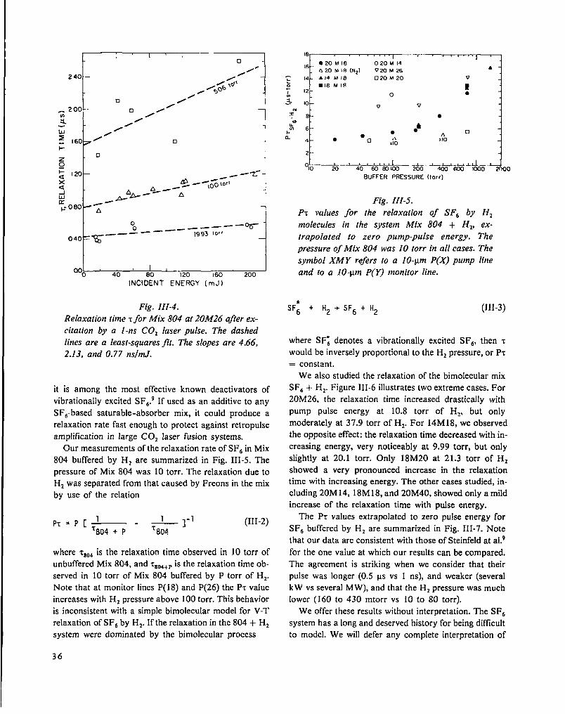
t
o0 __— — -———
040 –~————1993 to~~
7.o~40 80 I 20 160 200
INCIDENT ENERGY (mJ)
Fig. III-4.
Relaxation titne ~for Mix 804 at 20M26 after ex-
citation by a 1-ns CO= laser pulse. The dashed
lines are a least-squares jlt. The slopes are 4.66,
2.13, and 0.77 ns/mJ.
it is among the most effective known deactivators of
vibrationally excited SF6.9 If used as an additive to any
SFG-based saturable-absorber mix, it could produce a
relaxation rate fast enough to protect against retropulse
amplification in large COZ laser fusion systems.
Our measurements of the relaxation rate of SF6 in Mix
804 buffered by Hz are summarized in Fig. III-5. The
pressure of Mix 804 was 10 torr. The relaxation due to
Hz was separated from that caused by Freons in the mix
by use of the relation
PT=P[’ T—1 -1’804 + P - ~aoa
(111-2)
where ~80dis the relaxation time observed in 10 torr ofunbuffered Mix 804, and ~804+Pis the relaxation time ob-
served in 10 torr of Mix 804 buffered by P torr of Hz.
Note that at monitor lines P( 18) and P(26) the P~ value
increases with H2 pressure above 100 torr. This behavior
is inconsistent with a simple bimolecular model for V-T
relaxation of SFG by Hz. If the relaxation in the 804 + H2
system were dominated by the bimolecular process
18- --
16-● 20M18 020M14620 Mltl [N21 VKIMZ6
“’’” 7
A
c 14 - A14 M18 ❑ 20M20
: ● 18 MI17 ;7 12 – o ●
~ ,0_v v
4’ ~_ ●~mm 6 - ●&
1.●
● An
a4 - ● o d\ x 10
,10
2 -
ol~.~ #6. J-,,=% .*..Jmoo
BuFFER PRESSURE (Iorr)
Fig. III-5.
P~ values for the relaxation of SFb by Hz
molecules in the system Mix 804 + Hz, ex-
trapolated to zero pump-pulse energy. The
pressure of Mix 804 was 10 torr in all cases. The
symbol XA4Y refers to a 10-pm P(X) pump line
and to a 10-pm P(Y) monitor line.
SF; + H2 + SF6 + H2 (III-3)
where SF: denotes a vibrationally excited SF6, then r
would be inversely proportional to the H2 pressure, or P~
= constant.
We also studied the relaxation of the bimolecular mix
SF6 + H2. Figure III-6 illustrates two extreme cases. For
20M26, the relaxation time increased drastically with
pump pulse energy at 10.8 torr of Hz, but only
moderately at 37.9 torr of Hz. For 14M 18, we observed
the opposite effect: the relaxation time decreased with in-
creasing energy, very noticeably at 9.99 torr, but only
slightly at 20.1 torr. Only 18M20 at 21.3 torr of Hz
showed a very pronounced increase in the relaxationtime with increasing energy. The other cases studied, in-
cluding 20M 14, 18M 18, and 20M40, showed only a mild
increase of the relaxation time with pulse energy.
The P~ values extrapolated to zero pulse energy for
SF6 buffered by Hz are summarized in Fig. III-7. Note
that our data are consistent with those of Steinfeld at al.g
for the one value at which our results can be compared.
The agreement is striking when we consider that their
pulse was longer (0.5 vs vs 1 ns), and weaker (several
kW vs several MW), and that the Hz pressure was much
lower ( 160 to 430 mtorr vs 10 to 80 torr).
We offer these results without interpretation. The SF6
system has a long and deserved history for being difllcult
to model. We will defer any complete interpretation of
36
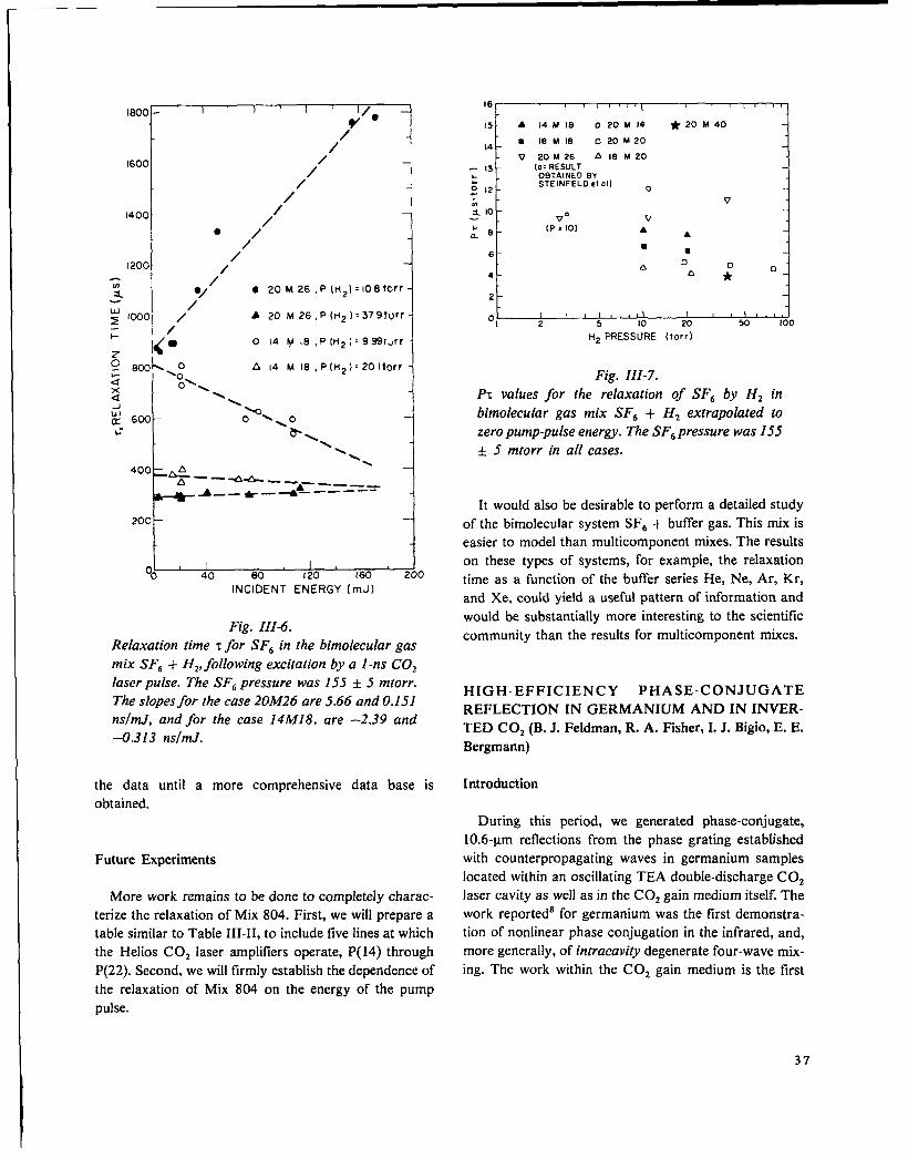
1800 - 1 I 1 I/e ‘
/“
i
/4
1600/’ —1
/ -.
/ I
1400 / —/
● /“
I 200/’
//
~ ●/ ● 20 M26, P(t12)=108tOrr
/; 10001 / A 20 M26, P(H2)=37SItUrf
1- 1/
1< gO 14 F+ 18 ,P (H2 ]= 9.991~rr
5~ r3C&: A 14 M 18, P(H2):201torr
dx
L
o~ \4 \J \
b~ 6C0 O\
\&k.- \
\\\
400 ~\,
A -—4& ——A— -_ __A -- * —+ ——— ---
20;l40 80 I 20 160
INCIDENT ENERGY (mJ)
Fig. III-6.
Relaxation time ~for SFb in the bimolecular gas
mix SFb + HZ,follo wing excitation by a 1-ns COZ
laser pulse. The SFb pressure was 155 & .5 mtorr.The slopes for the case 20M26 are 5.66 and 0.151
ns/mJ, and for the case 14&l18, are
-0.313 ns/rnJ.
the data until a more comprehensive
obtained.
Future Experiments
More work remains
)
–2.39 and
data base is
to be done to completely charac-
terize the relaxation of Mix 804. First, we will prepare a
table similar to Table III-II, to include five lines at which
the Helios C02 laser amplifiers operate, P(14) through
P(22). Second, we will firmly establish the dependence of
the relaxation of Mix 804 on the energy of the pump
pulse.
151 A 14 M 18 020M14 *20M40-i
141
8 18 M 18 020M20
V .20M26 A18M20 ~- 13
1
[o= RESULT. OBTAINED BY.~ 12
sTEINFELD e{ allo
> v-* 10-1 V“ v
(P x 10):8 AA
4
2‘1o,~2 5 10 20 50 100
H2 PRESSURE (?orr)
Fig. III-7.
P~ values for the relaxation of SFe by Hz in
bimolecular gas mix SFb + Hz extrapolated to
zero pump-pulse energy. The SFe pressure was 155
● 5 mtorr in all cases.
It would also be desirable to perform a detailed study
of the bimolecular system SFb + buffer gas. This mix is
easier to model than multicomponent mixes. The results
on these types of systems, for example, the relaxation
time as a function of the buffer series He, Ne, Ar, Kr,
and Xe, could yield a useful pattern of information and
would be substantially more interesting to the scientific
community than the results for multicomponent mixes.
HIGH-EFFICIENCY PHASE-CONJUGATE
REFLECTION IN GERMANIUM AND IN INVER-
TED COZ (B. J. Feldman, R. A. Fisher, I. J. Bigio, E. E.
Bergmann)
Introduction
During this period, we generated phase-conjugate,
10.6-~m reflections from the phase grating estabLished
with counterpropagating waves in germanium samples
located within an oscillating TEA double-discharge CO,
laser cavity as well as in the COZ gain medium itself. The
work reported8 for germanium was the first demonstra-
tion of nonlinear phase conjugation in the infrared, and,
more generally, of intracavi~ degenerate four-wave mix-
ing. The work within the COZ gain medium is the first
37
demonstration of infrared phase-conjugation in an inver-
ted medium. These intracavity techniques have general
applicability for any laser system.
In such a conjugation process, a nonlinear interaction
(such as stimulated Raman scattering, stimulated
Brillouin scattering, or degenerate four-wave mixing)
causes a “reflected” wave, which is the amplitude com-
plex conjugate of the incident wave. Characteristic of the
process is the fact that a phase-conjugate reflection
exactly retraces the optical path of an incident wave,
regardless of any phase distorters that may be in the
path of the incident wave. In contrast to a normal mirror
(which inverts only the component of the k-vector nor-
mal to its surface), a conjugating mirror inverts all three
components.
Conjugate optics can improve the double-pass opera-
tion of laser amplifiers. As a high-quality optical beam
traverses an optical system, it is unavoidably distorted
because of imperfections, improper surfaces, and in-
homogeneities in the gain medium. If the distorted beam
is reflected by a phase conjugator, it is redirected in such
a way that each distorted ray returns to its
corresponding aberrating spot and the beam emerges
with excellent optical quality. If so, large optical systems
could be arranged so that there are many elements
whose imperfect optical quality would not impair the
passage of a diffraction-limited beam, and this could
result in large savings for high-power laser designs.
Among the many potential applications of such a
phase-conjugator, the application to laser fusion is
perhaps the most exciting. In one arrangement, the fu-
sion target is diffusely illuminated. The scattered light
could travel backward through the amplifier chain, be
rellected by a conjugating four-wave mixing medium,
and return through the imperfect optical elements; an
amplified pulse would then impinge directly on the
target, obviating the need for ultraprecise target align-
ment, Such a phase-conjugating mirror will undoubtedly
find other applications, such as providing stable laser
operation even in a gain medium experiencing time-
varying inhomogeneities, and, possibly, diagnosing laser-
plasma interactions.
How Four-Wave Mixing Produces Phase Conjugation
For the simplest example of this effect, consider a
material in which the index of refraction depends linearly
upon intensity. Such a material would, for example,
cause strong self-focusing or strong self-defocusing
(depending on whether the refractive index increased or
decreased with intensity). The nonlinear response can be
described as an index of the form n = nO+ nz <Ez>, or
as a polarizability z = ~(o) + X(3)E2. The coefficients are
related through nz = 2rtX(3)/nW
Consider waves E,, Ez, and EJ (all of the same fre-
quency) propagating through this nonlinear material.
Waves El and Ez are arranged to be precisely counter-
propagating plane waves, and both are assumed to be far
stronger than E3. In the simplified theory, the pair of op-
positely propagating (pump) waves (at the same fre-
quency co) in a material exhibiting a nonlinear index of
refraction, provides the conditions for which a third
(probe) wave E3, also at frequency O, incident on the
material from any direction, would result in a fourth
wave being emitted from the sample precisely retracing
the k-vector of the third wave. Although a nonlinear
phenomenon is utilized, the effect is linear in the field to
be conjugated. Therefore this technique is far more at-
tractive than, say, stimulated Brillouin backscattering.
Because the effect is linear, a superposition of Ej’s will
generate a corresponding superposition of Ex’s, and one
can readily see that any complex field is time-reversed in
such an arrangement.
It is valuable to consider how the interference gives a
conjugated Eq wave. Consider first the interaction of theweak wave E3 and of one strong wave El. The index
change contains the term (E, + E3)2, which includes a
cross term corresponding to- a phase grating perfectly
phase-matched so that the other strong wave Ez is
Bragg-scattered into the Eq wave. Concurrently, E2 and
E3 interfere to form a phase grating that scatters El into
the Ed wave. This process is analogous to volume
holography in which the writing and reading are done
simultaneously.
Experimental Results in Germanium. Numerous
demonstrations of extracavity phase-conjugate reflection
via degenerate four-wave mixing in the visible have been
described recently. These experiments used beams from
frequency-doubled YAG lasers, from dye lasers, from
ruby lasers, and from cw argon-ion lasers; four-wave
mixing media included liquid CS2; resonant, near-
resonant, and two-photon resonant absorbing sodium
vapor; and ruby crystal. Yet, before our work, no experi-
ments had been performed at 10.6 ~m. Demonstrating
this effect in the infrared was made difficult because (1)
38
the effect has an mzdependence, andthus, is reduced by
a factor of 400 from the corresponding visible effect, (2)
very strong pump waves are needed, and (3) the pump
waves must be perfectly collimated and precisely
ret redirected.
We recognized that one could reduce the constraints
on the pump waves by requiring that they merely be
complex conjugates of each other. This means that if El
is diverging, Ez must be converging, and vice versa.
Because the two counterpropagating waves inside an os-
cillating laser cavity are already complex-conjugates of
each other. if the nonlinear material is p!aced within the
cavity of an oscillating stable-mode laser, the material is
guaranteed to be a conjugator for light of the laser fre-
quency. As an added bonus, the circulating power within
a laser can be much higher than the output power.
In our first experiments,8$10 we obtained 2’% phase-
conjugate reflection by reversing a 95 L?40flat germanium
output coupler so that the substrate was internal to the
optical cavity. The laser output was then used to probe
the sample’s conjugate reflectivity. In our recent experi-
ments, we used thicker germanium samples. A 2.5-cm-
thick. 95% reflecting end piece gave a conjugate reflec-
tivityy of 10%, whereas a 15-cm-long single-crystal boule
placed in the center of the cavity gave 20’?40conjugate
reflection efficiency. The effect did not scale simply as
the sample length squared because, as the length of the
nonlinear sample was increased, the circulating power
within the cavity decreased. This behavior may be due to
the intensity-dependent formation of an electron-hole
plasmall in the germanium, to surface damage, or to
phase-front durations of the pump waves due to non-
linear refraction. To verify that the gain medium does
not impair the conjugation effect, we first passed the
beam through a different path in the amplifier on the
way to the germanium conjugator. When including the
gain of the amplifier, the effective conjugate reflectivity
of the hybrid system was 40% (using a 0.5-cm-thick ger-
manium conjugator).
Conjugate Reflection in Inverted COZ
In the second set of experiments, we chose to obtain
conjugation using the nonlinear properties of the
resonance associated with the COZ gain medium itsel~
and again, our intracavity technique used the counter-
propagating waves already present in the oscillating laser
cavity. As an added bonus of working with the non-
linearity of a partially saturated gain medium, the phase-
conjugate signal is automatically amplified if the probe
beam is directed through “unused” gain volume on its
way to and from the interaction regio”n.
The nonlinear process used in the COz gain resonance
is not merely the four-wave mixing process; because of
saturation. the effett is the coherent superposition of
four-wave. six-wave, eight-wave, ... processes. Because
of the ambig~lty in the number of waves involved, we
prefer to identify this mixing process as resonant light-
by-light scattering. The theory of phase-conjugate reso-
nant light-by-light scattering was first developed byAbrams and Lind.12 They used the well-known nonlinear
susceptibility of a homogeneously broadened two-level
absorber (or amplifier) which, on resonance, sets up an
amplitude grating that couples the standing field and the
probe field to generate the conjugate wave. As should be
expected. the maximum scattering efficiency is attained
when the strong counterpropagating standing waves
only partially saturate the transition. Consequently, a
limitation occurs because the depth of the amplitude
grating becomes reduced as the strong waves exceed the
saturation flux, an-d this, in turn, explains why the effect
is not merely a third-order (four-wave) process.
In this experimental setup, our conventional hybrid
high-pressure/low-pressure TEA laser is operated with a
10-m radius of curvature, a 35 Yoreflecting mirror, and a
flat 10VOreflecting mirror. These unusually low reflec-
tivities were chosen to reduce the circulating power
within the cavity. The laser operated on the P(20) line of
the 10-~m COZ branch; the pulse emitted from the
curved output coupler “was -150 ns (FWHM) and h-ad
an energy of -100 mJ. This corresponded to a cir-
culating intensity of -1.5 MW/cm2 inside the cavity.
The output of the laser was attenuated, passed through a
beam splitter, and redirected through the TEA laser gain
medium. Phase-conjugate reflectivity was diagnosed by
using an infrared vidicon or a high-speed SAT detector
on the return-signal reflection from the beam splitter.
The phase-conjugate nature of the reflected light was
confirmed by studying the spatial characteristics of the
beam in the presence of an aberrator and in the presence
of a cross-hair image placed on the beam in front of the
beam splitter. In both cases the initial incident probe-
beam image was preserved in the reflected image. In a
single-pass configuration where the probe beam overlap-
ped the lasing region of the gain medium only in the last
10 cm of the 9 1-cm discharge length, effective reflec-
tivity was 0.5% (reflectivity defined as the peak intensity
39

of the phase-conjugate beam divided by the peak inten-
sity of the incident probe beam). In a double- and triple-
pass arrangement, where only the last 10 cm of the final
pass through the gain medium overlapped, the lasing-
region reflectivities were 35 and 250%, respectively. The
enhanced reflectivity in these cases is due entirely to the
amplification of the outgoing probe and incoming phase-
conjugate signal en route to and from the conjugation
region. The actual phase-conjugate reflectivity in the 10-
cm overlap region is, in all cases, less than 10–2, in ac-
cord with the Abrams and Lind theorylz for the field and
gain-medium parameters involved.
Concluding Remarks
We demonstrated that a very simple intracavity
arrangement is useful in obtaining phase-conjugate
reflections. The technique is readily applicable to any
nonlinear material placed in an oscillating laser cavity; if
the laser operates, the material is guaranteed to be a con-
jugate reflector for light of that frequency. Table III-III
indicates the conjugate reflectivities we obtained.
By using this technique, we demonstrated for the first
time a phase-conjugate reflection in the infrared using
both germanium and the COZ gain medium itself.
TABLE 111-111
PHASE-CONJUGATION RESULTS IN THE
INFRARED OBTAINED WITH GERMANIUM
Interaction Power
Length (cm) (MW/cm2) Reflectivity (%)
1 40 2
2.54 8.7 0.8
5.08 8.7 2.3
5.08 8.0 3.4
10.16 8.0 10.3
15 25 20
Hybrid 12 40
CALCULATION OF SMALL-SIGNAL GAIN
COEFFICIENTS IN COZ (J. C. Goldstein)
The small-signal gain coefficient of a COZ amplifier is
frequently used as a measure of the energy stored in the
device, and therefore, as an indicator of the amplifier’s
performance. The stability of a laser amplifier system
with respect to the growth of spurious parasitic modes of
oscillation-and the suppression of such parasitic by
saturable absorbers—is determined in large measure by
the magnitude and frequency variation of the small-
signal gain coefficient. It is important, therefore, to be
able to infer accurately the molecular energy-level pop-
ulation densities from small-signal gain measurements,
and conversely, to be able to predict the small-signal
gain coefllcient from calculated medium conditions
(such as vibrational and rotational temperatures).
The usually straightforward relationship of the small-
signal gain coefficient to molecular populations is
somewhat obscured in C02 by the presence of gain on
many closely spaced lines. The gain coefficient at any
particular frequency is the sum of the gains, each one
evaluated at that frequency, contributed by many dif-
ferent transitions. In addition to the contributions from
various rotational lines of the main vibrational transition
(the 00°1 ~ 10°0 transition in the case of the 10.6-~m
band), there can also be contributions from transitions
between higher lying vibrational states due to near coin-
cidences of some of the rotational lines of these transi-
tions with those of the main transition.
We constructed a code to compute the small-signal
gain coefficient at any specified frequency by summing
over P- and R-branches of the following transitions inCov
10 ~m 9 Km
00°14 10”0 main 00”1+ 02”000”2 + 10”1 sequence 00”2 + 02”100”3 + 10”2 sequence 00”3 + 02”201’1+ 11’0 hot 01’1 + 03’0
40
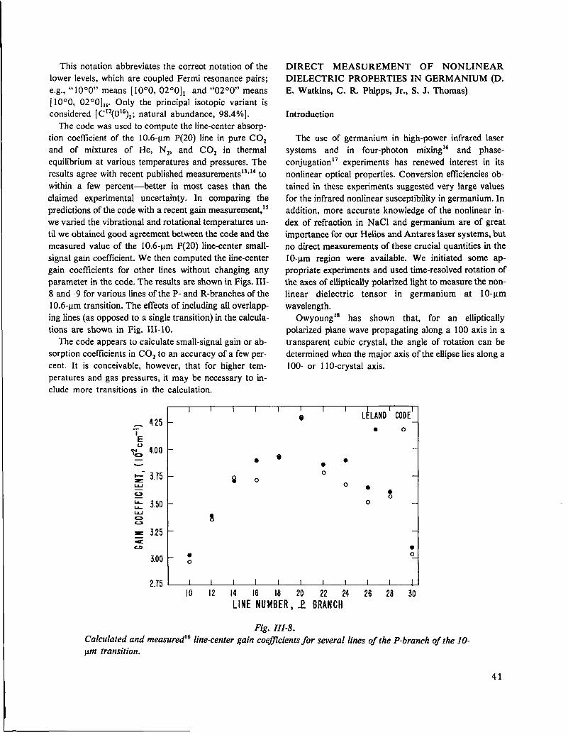
This notation abbreviates the correct notation of the
lower levels, which are coupled Fermi resonance pairs;
e.g., “ 10°0” means [10°0, 02°0]1 and “02°0” means
[1000,0200]1,.Only the principal isotopic variant is
considered [C12(016)Z; natural abundance, 98.4%].
The code was used to compute the line-center absorp-
tion coefficient of the 10.6-~m P(20) line in pure C02
and of mixtures of He, N2, and COZ in thermal
equilibrium at various temperatures and pressures. The
results agree with recent published measurements 13$14to
within a few percent—better in most cases than the
claimed experimental uncertainty. In comparing the
predictions of the code with a recent gain measurement,*s
we varied the vibrational and rotational temperatures un-
til we obtained good agreement between the code and the
measured value of the 10.6-~m P(20) line-center small-
signal gain coefficient. We then computed the line-center
gain coefficients for other lines without changing any
parameter in the code. The results are shown in Figs. IH-
8 and -9 for various lines of the P- and R-branches of the
10.6-~m transition. The effects of including all overlapp-
ing lines (as opposed to a single transition) in the calcula-
tions are shown in Fig. III-10.
The code appears to calculate small-signal gain or ab-
sorption coetlicients in COZ to an accuracy of a few per-
cent. It is conceivable, however, that for higher tem-
peratures and gas pressures, it may be necessary to in-
clude more transitions in the calculation.
DIRECT MEASUREMENT OF NONLINEAR
DIELECTRIC PROPERTIES IN GERMANIUM (D.
E. Watkins, C. R. Phipps, Jr., S. J. Thomas)
Introduction
The use of germanium in high-power infrared laser
systems and in four-photon mixinglb and phase-
conjugation17 experiments has renewed interest in its
nonlinear optical properties. Conversion efficiencies ob-
tained in these experiments suggested very large values
for the infrared nonlinear susceptibility in germanium. In
addition, more accurate knowledge of the nonlinear in-
dex of refraction in NaCl and germanium are of great
importance for our Helios and Antares laser systems, but
no direct measurements of these crucial quantities in the
10-~m region were available. We initiated some ap-
propriate experiments and used time-resolved rotation of
the axes of elliptically polarized light to measure the non-
linear dielectric tensor in germanium at 10-urn
wavelength.
Owyoung16 has shown that, for an elliptically
polarized plane wave propagating along a 100 axis in a
transparent cubic crystal, the angle of rotation can be
determined when the major axis of the ellipse lies along a
100- or 110-crystal axis.
8
1 I i I I I I I I I
_ 425 –@ LELAND CODE1
-i- ● 0
Ey: 4.00-— ●
e●
●
~- 3.75 080
w o●
z ●
E 350 -0
0
0
= 3.25z
●
3.00-:0
2.75 1 I I I I I I 1 I I 1
10 12 14 16 18 20 22 24 26 28 30
LINENUMBER,1 BRANCH
Fig. III-8.Calculated and measuredlb line-center gain coeflcients for several lines of the P-branch of the 10-
pm transition.
41
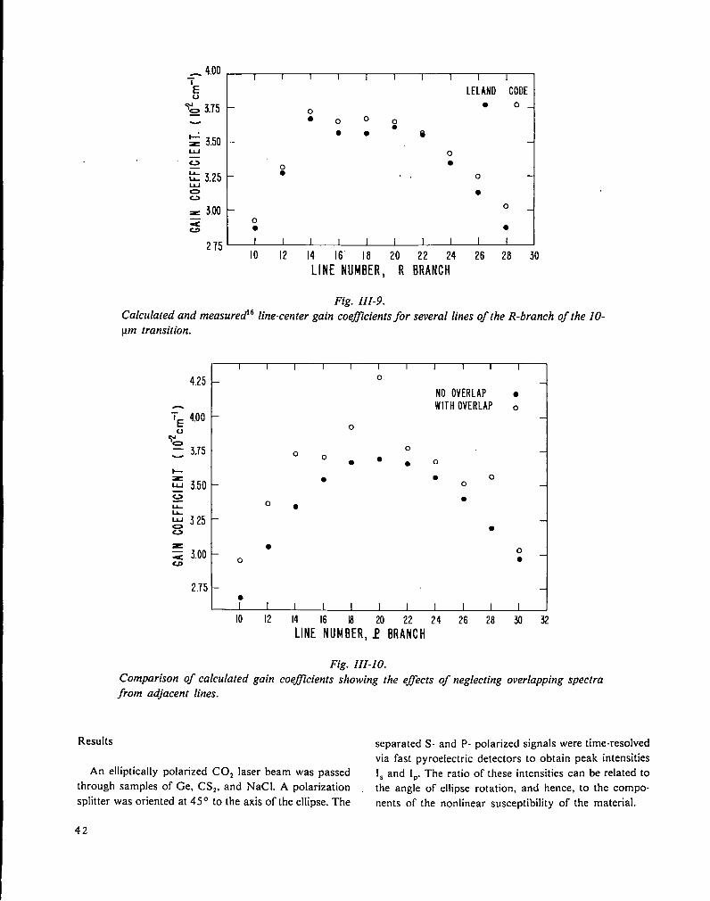
_ 4.00-i I I I I I I i I I 1
E LELAND CODE
g 3.75 ● o0● o 0 0
●● ● @
z 3.50w oG o ●
c ● ., 0~ 3.250 ●
= 3.00- 0
z o● ●
275- ,: I I I I I I I I I
12 14 16” 18 20 22 24 26 28 30LINENUMBER, R BRANCH
Fig. III-9.Calculated and measuredlb line-center gain coeflcients for several lines of the R-branch of the IO-
pm transition.
4.25
L
: 3.50
z
2.75
I I [ I I I I I I I I
o
0 0●
●
o●
●
o
●
I I 1 I
o
NO OVERLAPWITHOVERLAP
o●
● o
● o0
●
●
I I I I I
●
o
0●
10 12 14 16 la 20 22 24 26 28 ~ Q
LINENUMBER,1 BRANCH
Fig. III-IO.Comparison of calculated gain coefficients showing the efects of neglecting overlapping spectra
from adjacent lines.
Results separated S- and P- polarized signals were time-resolved
via fast pyroelectric detectors to obtain peak intensities
An elliptically polarized C02 laser beam was passed Is and [P. The ratio of these intensities can be related tothrough samples of Ge, CS2, and NaC1. A polarization the angle of ellipse rotation, and hence, to the compo-splitter was oriented at 450 to the axis of the ellipse. The nents of the nonlinear susceptibility of the material.
42

I .U ~
0.90 -
080H“\
H* 0,70
0.60 -
,,.● ☛
I I J
ELLIPSE ROTATION IN 12cmlNTRINSICGe, 110 AXIS.
1221X3 = I 3x16” esu
●
●
8●
0.50 I I 1 b I0.1 I .0 10 100
PEAK INTENSITY (MW/cm2)
Fig. III-1 1.
Dependence of ratio I,:IP on peak intensity for the
value of nonlinear susceptibility ~, given. The dots
are experimental values.
Our system was calibrated against CS2. In 10 cm of
CSZ. we found Z~221= (3.9 + 1.0) x 10-13 esu compared
to (4.7 + 1.6) x 10-13 esu reported by Moran et al.lg
Measurements made on a 12-cm-long single-crystal
intrinsic germanium sample are shown in Fig. III- 11.
The values obtained from this sample are z;ll = (2.5 +
0.3) x 10-11 esu and ~~1 = (1.3 * 0.2) x 10-11 esu.
These values are substantially lower than previously
reported. Wynne20 used third-order optical mixing to in-
fer ~\’l = (1 + 0.5) x 10-10 esu and X~22’ = 0.6 x~***.
However, recent work in four-photon mixing16 and
phase conjugation 17 has produced smaller effeCtS than
expected on the basis of Wynne’s work.
A 17.8-cm-long piece of polycrystalline NaCl
produced no measurable result. This experiment would
have been sensitive to ~~221= 3 X 10-14 esu in NaCl,
consistent with Smith et al.,21 who found ~]221 = (2.6 +
1.3) x 10-’4 esu via four-photon mixing in NaCl at 1.06
~m.
The results for germanium indicate a lower efllciency
for four-photon mixing and phase conjugation than
previously assumed. Also, they imply a l/4-wavelength
distortion for intensity-length products of -0.5 GW/cm,
which has been confirmed by brightness degradation
measurements. zz In NaCl, these measurements imply
that 1/4-wavelength phase distortion will occur for
intensity-length products that are greater than 45
GW/cm. Further measurements with 20 times greater
sensitivity are under way to correct the upper bound
reported here with accurate measurements of %Jin NaC1.
SUBNANOSECOND EXTINCTION OF CO,
LASER SIGNALS VIA BULK PHOTOIONIZA-
TION IN GERMANIUM (C. R. Phipps, Jr., S. J.
Thomas, D. E. Watkins)
Introduction
Recent reports of efficient phase conjugation23 and
four-wave mixing24 of C02 laser signals in germanium
have renewed interest in the nonlinear optical properties
of this material. The ultimate efilciency of these
processes is limited by the magnitude of the nonlinear
susceptibility and by the intensity-length product
available in the interaction region. The former is
somewhat smaller than had been supposed,2s and the
useful interaction length has practical limits set by loss,
nonlinear refraction, or the signal duration itself.
We found that a definite intensity limit also exists for
propagation in intrinsic or optical-grade germanium,
determined by the sudden onset of bulk photoionization
at levels only moderately higher than those required for
eflicient mixing or conjugation. The threshold intensity
was relatively independent of wavelength in the 9- to 10-
~m region, and varied only slightly for pulse durations
ranging from 1 to 50 ns. Ionization thresholds were
lower in optical grade than in intrinsic material, but
much higher in p-type gallium-doped germanium.
Because the saturation intensityzc of the intraband hole
absorption is 3.2 M W. cm–2, and because the Abrams-Lind Mode127 predicts efilcient phase-conjugation in
such saturable absorbers, the increased threshold in p-
type germanium may permit the attainment of four-wave
mixing eftlciencies considerably higher than those seen
previously.
Experiments and Results
The effects studied were completely reversible, using
intensities well below surface damage thresholds. Bulk
ionization was revealed by transverse photoconductive
signals with decay times varying from nearly 1 ms in
pure germanium to 50-100 VS in optical-grade material.
These results were consistent with absorption decay
rates observed in low-power, 9-vm probe measurements.
Transmission was measured for intense, collimated,
single- or multiline C02 laser signals in samples of
various lengths. Both time-averaged and instantaneous
quantities were measured; time resolution of our
diagnostic system was 100 ps.
43

The time-resolved data for uniform illumination
clearly show that the instantaneous, high-intensity
transmission function drops to zero (irreversibly on
nanosecond time scales) whenever the input intensity ex-
ceeds a critical value Ib N 200 MW.cm-2. The peak out-
put intensity is essentially a constant, and the fall time of
the output signal can be as small as 400 ps, indicating
very rapid plasma formation.
Bearing in mind that absorption in germanium is
dominated by the intravalence-band transitions in this
spectral range, and taking proper account of saturation,
we infer peak photoplasma densities of 2 x 1015 cm–3
from the experimental transmission data, as indicated in
Fig. III- 12.
We also used a second method to measure the non-
linear transmission properties of germanium, with the in-
put COZ laser beam brought to a real internal focus. We
observed that internal damage was prevented by plasma
formation. In addition, the transmission for a space-time
Gaussian beam in this configuration was highly predic-
table over four orders of magnitude in input intensity.
Applications of this highly reproducible transmission
function include passive intensity-limiting for detector
protection, and passive pulse-shortening. An additional
application of this work is passive intensity-range com-
pression for more effective comparison of prepulses and
main pulses in target-illumination diagnostics, where the
2
t
I&j.100 200 300 403
PEAK INPUT INTENSITY (MW cm-z)
Fig. 111-12.
Free carrier densities vs input intensity inferred
from residual transmission measurements on ger-
manium samples for lengths of 5.7 cm (0), 9.7 cm
(A), and 14.2 cm (~. The trend line represents n K
P.
44
intensities to be compared differ by many orders of
magnitude.
HIGH-PRESSURE ENRICHMENT OF LIGHT
ISOTOPES (J. B. Marling, I. P. Herman, LLL; S. J.
Thomas)
Introduction
A series of joint LLL-LASL experiments, designed to
demonstrate enhanced deuterium enrichment in certain
Freon compounds by using ns-duration C02 laser
signals, was completed successfully at LASL. Higher
than 1000-fold enrichment was obtained, and the short
laser pulses permitted the use of relatively high gas
pressures for this type of work.
Laser separation of light isotopes by multiple-photon
dissociation is becoming more attractive, using pulsed
C02 lasers as an excitation source. Very high single-step
enrichment factors were observed when the proper work-
ing molecule was chosen. For deuterium separation,
single-step enrichment factors above 1000 with high
yield have been obtained in 2,2-dichloro- 1,1,1, -
trifluoroethane (Freon 123) at 0.5 torr using standard
C02 TEA laser technology near 10.65 ~m.2* For *3C
separation, single-step enrichment factors up to 65 were
observed in CFJBr at room temperature,29 but enrich-
ment dropped rapidly above 1 torr.29
Extension of these performance parameters into the
100-times higher pressure regime is essential to reduce
gas pumping costs to competitive levels and to achieve a
realistic photochemical reactor size, especially for
deuterium separation. Deuterium and 13C enrichment us-
ing these molecules was studied experimentally and is
reported here as a function of pressure and incident
fluence for a variety of COZ laser pulse lengths (2 to
1000 ns).
Experiment and Results
o
The C02 laser used was either an oscillator-amplifierwith variable short-pulse duration or (at LLL) a stan-
dard TEA laser with a 100-ns gain-switched initial spike
followed by a weak 1-us tail. The LASL oscillator was
modelocked with a 12-ns switchout gate for selection of
a single 2-ns FWHM pulse for amplification. With the
modelocker turned off, a 12-ns FWHM pulse was
switched out for amplification. Pulses of 80 ns without

tails were available by bypassing both the switchout and
modelocker, and by controlling the laser gas composi-
tion.
We evaluated deuterium using mixtures of CF~CHC12
(Freon- 123) containing -0.4V0 CF3CDC11. We also per-
formed several experiments using Freon- 123 with
natural deuterium isotopic abundance (-0.015% D).
The primary deuterium-containing photoproduct is
trifluoroethene, (C Fz = CFD),28 and the isotope content
of the product was determined by mass spectrometry.
The CFJBr (bromotrifluoromethane) decomposes to
yield *3C-enriched CF3CFJ as primary photoproduct;29
CF3Br of natural isotopic abundance, containing -1.1 YO
13C. was always used. For deuterium separation, we
used the P(26) 10.65-ym line for photolysis, and for ‘3C,
we used the P(24) 9.59-~m COZ laser line.
In the initial 13C enrichment studies in CFJBr, repor-
ted in Ref. 29, the low-pressure single-step enrichment
factor of 65 dropped 50% by 0.8 torr and dropped 10-
fold by 3 torr. By using 2-ns C02 laser pulses in our
study, the single-step ‘3C enrichment factor at 3 torr was
43. It decreased as a very slow function of pressure to 27
at 100 torr, and to 22 at 225 torr.
Deuterium enrichment was measured by using 12-ns
dissociating pulses at a peak focal fluence of 8 to 10
J/cm2. The single-step deuterium enrichment factor was
constant at 900 + 50 in the trifluoroethene product over
the range 1 to 600 torr. However, the yield at 100 torr
was too low to determine isotopic enrichment. Hence,
high pressure quenched the photoproduct yield without
decreasing the enrichment. Use of shorter (2-ns) dis-
sociating pulses again resulted in near- 1000-fold enrich-
ment, but with apparently higher yield because we ob-
tained a sufficient amount of photoproduct at 100 torr
for isotope analysis. Freon- 13 of natural isotopic abun-
dance was also examined, and yielded a deuterium
enrichment factor of 1900 + 400 at 30 torr, and of 1500
+ 100 at 100 torr. The use of relatively long (80-ns) dis-sociating pulses did not significantly decrease the
isotopic enrichment at higher pressures. However, a
higher fluence of 20 J/cm2 was used, reducing overall
enrichment (see Fig. 2 of Ref. 28), but it remained as
high as 220 + 50 throughout the pressure range from 0.3
to 30 torr.
In ir photolysis of a sample in which the minority
isotope is the absorbing molecule, the effect of collisions
on yield should be analyzed as a function of laser
fluence. Above the saturation fluence (for the resonantly
absorbing molecule of the minority), an increase in
pressure can lead to increased ir dissociation of the non-
resonant species, which can absorb photons only after
collisions with the resonant molecule. The increase oc-
curs without greatly decreasing the association yield of
the resonantly absorbing minority isotope. Therefore, at
high !luences the isotopic enrichment will fall with in-
creasing pressure, perhaps with little change in yield.
However, at fluences between dissociation threshold and
saturation, collisions will quench the resonant isotope,
and the nonresonant species, therefore, will not be able
to dissociate. Consequently, as pressure increases, net
yield will fall, but isotopic enrichment may vary only
slightly. However, we ignore the importance of collisions
in removing the multiple-photon absorption bottleneck
that appears at very low fluences. Our conclusions seem
to be especially true for deuterium separation in Freon-
123 where the single-step enrichment factor is very
fluence-sensitive,28 but showed only slight sensitivity to
operating pressure.
Conclusion
The practicality of using lasers for the separation of
light isotopes has been greatly enhanced by
demonstrating that high single-step isotope enrichment
can be maintained even at pressures up to 1/3 atm.
Isotonically selective multiple-photon dissociation was
achieved with 2-ns C02 laser pulses, permitting 1500-
fold enrichment of naturally occurring deuterium in pure
Freon- 123 at 100 torr and 22-fold enrichment of ‘3C in
CF3Br at 225 torr.
The LASL part of this work was supported by the In-
ertial Confinement Fusion Program because of the ex-
istence of high-intensity, short-pulse C02 lasers. Im-
proved efllciency of deuterium separation will benefit the
fusion program by providing an improved fuel source.
REFERENCES
1. F. Skoberne, Comp., “Laser Fusion Program, July
1—December 31, 1977:’ Los Alamos Scientific
Laboratory report LA-7328-PR (December 1978).
2. B. J. Feldman, “Multiline Short Pulse Amplification
and Compression in High-Gain COz-Laser Am-
plifiers,” Opt. Commun. 14, 13 (1975).
45

3. H. C. Volkin, “Calculation of Short-Pulse Propaga-
tion in a Large COz-Laser Amplifier,” J. Appl.
Phys., to be published.
4. R. J. Harrach, “Effect of Rotational and Intramode
Vibrational Coupling on Short-Pulse Amplification
in COz.” IEEE J. Quantum Electron. QE-I 1, 349
( 1975).
5. E. E. Stark, Jr., “Measurement of the 10°0-0-0200
Relaxation Rate in COz,” Appl. Phys. Lett. 23, 335
(1973).
6. R. R. Jacobs, K. J. Pettipiece, and S. J. Thomas,
“Rate Constants for the COZ 020-100 Relaxation,”
Phys. Rev. A 11, 54 (1975).
7. G. T. Schappert, “Rotational Relaxation Effects in
Short-Pulse COZ Amplifiers:’ Appl. Phys. Lett. 23,
319 (1973).
8. F. Skoberne. Comp., “Inertial Fusion Program,
January 1—June 30, 1978,” Los Alamos Scientific
Laboratory report LA-7587-PR (May 1980).
9. J. 1. Steinfeld, 1. Burak, D. G. Sutton, and A. V.
Nowak, J. Chem. Phys. 52, 5421 (1970).
IO. E. E. Bergmann, I. J. Bigio, B. J. Feldman, and R.
A. Fisher. Opt. Lett. 3, 82 (1978).
11. C. R. Phipps, Jr., Los Alamos Scientific
Laboratory, private communication (1978).
12. R. L. Abrams and R. C. Lind, Opt. Lett. 2, 94
( 1978), and Erratum, Opt. Lett. 3, 205 (1978).
13. A. M. Robinson and Y. -K. Hsieh, J. Appl. Phys.
48. 1589 (1977).
14. A. M. Robinson and N. Sutton, Appl. Opt. 16,2632
(1977).
16. N. Lee, R. Aggarwal, and B. Lax, Opt. Commun. 9,
401 (1976).
17. E. Bergmann, I. Bigio, B. Feldman, and R. Fisher,
Opt. Lett. 3, 82 (1978).
18. A. Owyoung, LE.E.E. J. Quantum Electron. QE-9,
1064 (1973).
19. M. Moran, C. She, and R. Carman, I.E.E.E. J.
Quantum Electron. QE- 11, 259 (1975).
20. J. Wynne, Phys. Rev. 178, 1295 (1969).
21. W. Smith, J. Bechtel, and N. Bloembergen, Proc.
Laser Induced Boulder Damage in Optical
Materials, 7th Annual Symp. ( 1976), p. 321.
22. C. Phipps, Jr., Los Alamos Scientific Laboratory,
unpublished data (1978).
23. E. E. Bergmann, L J. Bigio, B. J. Feldman, and R.
A. Fisher, Opt. Lett. 3, 82 ( 1978).
24. N. Lee, R. L. Aggarwal, and B. Lax, Opt. Commun.
19, 401 (1976).
25. D. E. Watkins, University of Washington, un-
published data ( 1978).
26. C. R. Phipps, Jr., and S. J. Thomas, Opt. Lett. 1,93
(1977).
27. R. L. Abrams and R. C. Lind, Opt. Lett. 2, 94
(1978).
28. J. B. Marling and I. P. Herman, Appl. Phys. Lett. 34
(February 1979).
29. M. Gauthier, P. A. Hackett, M. Drovin, R. PiIon,
and C. Willis, Can. J. Chem. 56, 2227 (1978).
15. W. T. Leland, M. J. Kircher, M. J. Nutter, and G. T.
Schappert, J. Appl. Phys. 46, 2174 (1975).
46

IV. TARGET EXPERIMENTS, DIAGNOSTICS, AND
MILITARY APPLICATIONS
(G. H. McCall)
In an integrated program of target experiments, theory, and design, we are es-
tablishing a fundamental understanding of laser-target interactions, particularly of the
relevant plasma physics and hydrodynamics. Experimental and theoretical efforts have
addressed the scaling of consistent models to higher laser intensities. Emphasis has been
on the development and demonstration of experimental techniques that will determine
conclusively the performance of present and future targets. A modest experimental ef-
fort is directed toward military applications.
The laser fusion process calls for new diagnostic techniques having spatial and tem-
poral resolutions in the submicrometer and 1- to 100-ps regime. These needs are being
met with a vigorous diagnostics program in such areas as laser calorimetry, charged-
particle and neutron detection, x-ray spectrometry, and subnanosecond streak camera
development.
EXPERIMENTS (R. P. Godwin, D. B. Giovanielli)
Introduction
This reporting period was an exciting one. The Helios
laser is maturing as a complete laser-fusion research
facility. It has delivered previously unattainable CO,
laser power and energy to various targets. Exploding-
pusher GMB targets served as a test of the new facility
and verified our confidence in the understanding and in-
tensity scaling of those targets. Neutron yields exceeding
108 were obtained for the first time using Coz radiation
powers of 3 TW. In our first experiments, we used
plastic-coated GMB targets designed to achieve high fuel
density, but relatively low temperature. These targets
were direct predecessors of long-range fusion reactor
targets. Their neutron yields (up to 108) provided enough
data for statistically meaningful parametric studies. This
class of targets is sensitive to such important aspects of
laser fusion as hot-electron preheat, which is unimpor-
tant in exploding-pusher experiments. Although these
high-density targets are difficult to diagnose by simple
techniques that provide uniquely interpretable informa-
tion. initial experiments are providing information con-
sistent with our code calculations and are determining
our diagnostic development efforts, particularly in the
areas of neutron diagnostics with high temporal resolu-
tion and x rays. The measurement of the fastest plasma
protons at Helios gives additional support to the hot-
electron temperature scaling as (112)1’3, where I is the
focal power/area and k the laser wavelength, which has
proved to be a useful laser diagnostic. Energy transport
questions continue to be dominant in laser-plasma in-
teractions, particularly in the interpretation of experi-
ments. Conceptually simple experiments performed at
Gemini showed that electron currents flowing toward
targets through support structures, and through target
potentials of several hundred kV may be important vec-
torial factors in trans~ort—factors previously discoun-
ted in hydrodynamics calculations.
Helios Exploding-Pusher Experiments (D. Giovanielli)
Exploding-pusher experiments were the first to be un-
dertaken at the Helios laser facility. Because the
behavior of such targets is well known, they were chosen
for the first full-scale integration of laser operations,
beam diagnosis, alignment and focusing, target handling,
and target diagnosis systems. Performance of all of those
system elements can be normalized against earlier ex-
perience.
In (he first sequence, 32 DT-filled GMB targets were
irradiated with total laser energies varying from 750 to
4 i00 J. Simultaneity of the eight Helios laser beams was
previously measured to be within 50 ps. Several targets
were irradiated with fewer than eight beams, but the
suprathermal electrons, which drive the explosion of the
thin-walled glass shell, symmetrized the target. There
was no loss of ability to calculate target thermonuclear
47
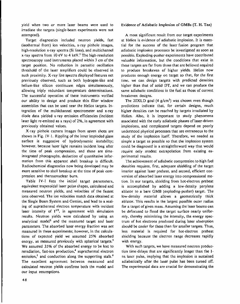
yield when two or more laser beams were used to
irradiate the targets (single-beam experiments were not
attempted).
Target diagnostics included neutron yields, fast
(isothermal front) ion velocities, x-ray pinhole images,
high-resolution x-ray spectra (Salines), and multichannel
x-ray spectra from 10eV to 4 keV.l The high-resolution
spectroscopy used instruments placed within 3 cm of the
target position. No reduction in parasitic oscillation
threshold of the laser amplifiers could be observed in
such proximity .X-ray line spectra display ed features not
previously observed, such as both hydrogen-like and
helium-like silicon continuum edges simultaneously,
allowing triply redundant temperature determinations.
The successful operation of these instruments verified
our ability to design and produce thin filter window
assemblies that can be used near the Helios targets. In-
tegration of the multichannel spectrometer and x-ray
diode data yielded x-ray emission efficiencies (incident
laser light re-emitted as x rays) of 2LX0, in agreement with
previously obtained values.
X-ray pinhole camera images from seven shots are
shown in Fig. IV-1. Rippling of the inner imploded glass
surface is suggestive of hydrodynamic instability;
however, because laser light remains incident long after
the time of peak compression, and these are time-
integrated photographs, deduction of quantitative infor-
mation from this apparent shell breakup is difficult.
Radiochemical diagnostics now being developed may be
more sensitive to shell breakup at the time of peak com-
pression and thermonuclear burn.
Table IV-I lists the initial target parameters,
equivalent trapezoidal laser pulse shapes, calculated and
measured neutron yields, and velocities of the fastest
ions observed. The ion velocities match data obtained at
the Single Beam System and Gemini, and lead to a scal-
ing of suprathermal electron temperature with incident
laser intensity of I 1’3, in agreement with simulation
results. Neutron yields were calculated by using an
analytical mode12 and the measured target and laser
parameters. The absorbed laser energy fraction was not
measured in these experiments; however, in the calcula-
tions of expected yield we assumed 25’?40 absorbed
energy, as measured previously with spherical targets.3
We assumed 35?40 of the absorbed energy to be lost to
reradiation, fast-ion production,’ suprathermal electron
emission? and conduction along the supporting stalk.c
The excellent agreement between measured and
calculated neutron yields confirms both the model and
our input assumptions.
Evidence of Adiabatic Implosion of GMBs (T. H. Tan)
A most significant result from our target experiments
at Helios is evidence of adiabatic implosion. It is essen-
tial for the success of the laser fusion program that
adiabatic implosion processes be investigated as soon as
possible. Exploding-pusher experiments have contributed
valuable information, but the conditions that exist in
these targets are far from those that are believed required
to produce breakeven of higher yields. Helios now
produces enough energy on target so that, for the first
time, we can design targets with predicted densities
higher than that of solid DT, and we can produce the
same adiabatic conditions in the fuel as those of current
breakeven designs.
The 20XLD goal (4 g/cm3) was chosen even though
predictions indicate that, for certain designs, much
higher densities can be reached by targets irradiated by
Helios. Also, it is important to study phenomena
associated with the early adiabatic phases of laser-driven
implosions, and complicated targets depend on poorly
understood physical processes that are extraneous to the
study of the implosion itself. Therefore, we needed as
simple a target as possible so that the implosion system
could be diagnosed in a straightforward way that would
require only modest extrapolation from existing ex-
perimental results.
The achievement of adiabatic compression to high fuel
densities requires, first, adequate shielding of the target
interior against laser preheat, and second, efficient con-
version of absorbed laser energy into compressional mo-
tion. In our targets, shielding from hot-electron preheat
is accomplished by adding a low-density parylene
ablator to a bare GMB (exploding-pusher) target. The
low-density material allows a geometrically thick
ablator. This results in the largest possible outer radius
for a target of given mass. Assuming the laser beams can
be defocused to flood the target surface nearly unifor-
mly, thereby minimizing the intensity, the energy spec-
trum of hot electrons produced during laser absorption
should be cooler for these than for smaller targets. Thus,
less material is required for hot-electron preheat
shielding because the electron range decreases rapidly
with energy.
With such targets, we have measured neutron produc-
tion time-delays that are significantly longer than the 1-
ns laser pulse, implying that the implosion is sustained
adiabatically after the laser pulse has been turned off.
The experimental data are crucial for demonstrating the
48
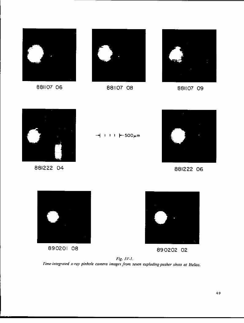
881107 06 881107 08
881222 04
881107 09
881222 06
890201 08 890202 02
Fig. IV-I.Time-integrated x-ray pinhole camera images from seven exploding-pusher shots at Helios.
49

ILux!3nm
-o.w
lnw
L--m
-00---
50
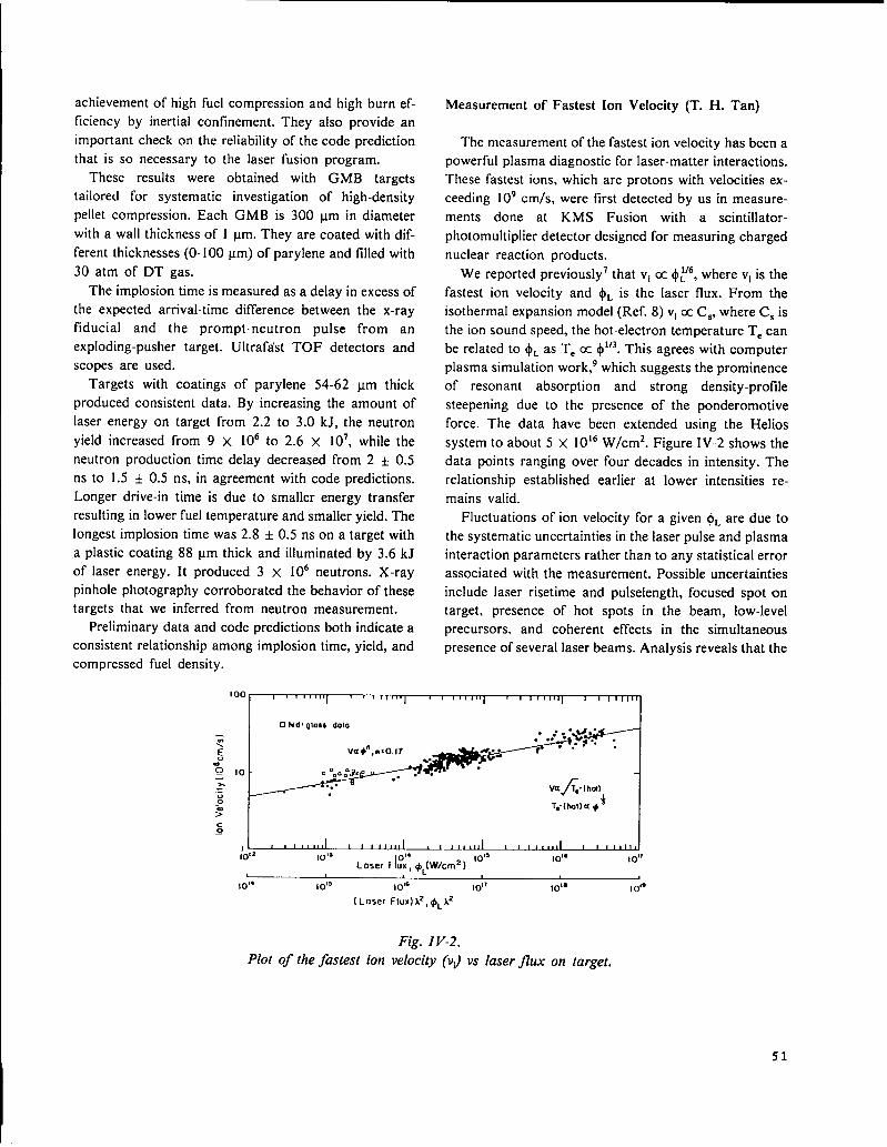
achievement of high fuel compression and high burn ef-
ficiency by inertial confinement. They also provide an
important check on the reliability of the code prediction
that is so necessary to the laser fusion program.
These results were obtained with GMB targets
tailored for systematic investigation of high-density
pellet compression. Each GMB is 300 ~m in diameter
with a wall thickness of 1 ym. They are coated with dif-
ferent thicknesses (O-100 ~m) of parylene and tilled with
30 atm of DT gas.
The implosion time is measured as a delay in excess of
the expected arrival-time difference between the x-ray
fiducial and the prompt-neutron pulse from an
exploding-pusher target. Ultrafdst TOF detectors and
scopes are used.
Targets with coatings of parylene 54-62 ~m thick
produced consistent data. By increasing the amount of
laser energy on target from 2.2 to 3.0 kJ, the neutron
yield increased from 9 x 10⁶ to 2.6 x 10⁷, while the
neutron production time delay decreased from 2 + 0.5
ns to 1.5 + 0.5 ns, in agreement with code predictions.
Longer drive-in time is due to smaller energy transfer
resulting in lower fuel temperature and smaller yield. The
longest implosion time was 2.8 + 0.5 ns on a target with
a plastic coating 88 ~m thick and illuminated by 3.6 kJ
of laser energy. It produced 3 x 10b neutrons. X-ray
pinhole photography corroborated the behavior of thesetargets that we inferred from neutron measurement.
Preliminary data and code predictions both indicate a
consistent relationship among implosion time, yield, and
compressed fuel density.
Measurement of Fastest Ion Velocity (T. H. Tan)
The measurement of the fastest ion velocity has been a
powerful plasma diagnostic for laser-matter interactions.
These fastest ions, which are protons with velocities ex-
ceeding 109 cm/s, were first detected by us in measure-
ments done at KMS Fusion with a scintillator-
photomultiplier detector designed for measuring charged
nuclear reaction products.
We reported previously’ that vi cc $~’b, where vi is the
fastest ion velocity and & is the laser flux. From the
isothermal expansion model (Ref. 8) vi a C~, where C~ is
the ion sound speed, the hot-electron temperature T. can1/3 This agrees with C(31TIPIterbe related to +, as T, cc $ .
plasma simulation work,9 which suggests the prominence
of resonant absorption and strong density-profile
steepening due to the presence of the ponderomotive
force. The data have been extended using the Helios
system to about 5 X 10ls W/cmz. Figure IV-2 shows the
data points ranging over four decades in intensity. The
relationship established earlier at lower intensities re-
mains valid.
Fluctuations of ion velocity for a given $~ are due to
the systematic uncertainties in the laser pulse and plasma
interaction parameters rather than to any statistical error
associated with the measurement. Possible uncertainties
include laser risetime and pulselength, focused spot on
target, presence of hot spots in the beam, low-level
precursors. and coherent effects in the simultaneous
presence of several laser beams. Analysis reveals that the
I 00 , I I I , , ,!0, , , rr,, 1 I 1 I 11s
: ~..~;.l 2 ,.,sLoser Ft’: #JW/Cn#) ‘o”
lo’* 10”
10’” 10” lo’~ 1o11 10” I o’*
( Loser Flud.i2, $LA2
Fig. IV-2.
Plot of the fastest ion velocity (vJ vs laser ji’ux on target.

cause of variation in ion velocity can be accounted for
by these kinds of uncertainties.
For any target design, two critical code inputs that
generate the simulated implosions are fraction of energy
absorbed and hot-electron temperature. The agreement
of the fast-ion data with the simulations implies that the
assumption of T,_ cc $#3 is still valid at an intensity of
1017 W/cm2. Because the analysis assumes a constant
absorption fraction, it suggests that the absorptance is
the same as that measured at lower intensity .10 Both in-
puts were incorporated into our high-compression target
design. The agreement between the experimental results
and calculations *1bears out the diagnostic capability of
fast-ion detection.
We have also established direct correlation between
fast-ion spectrum and target implosion as seen by the x-
ray pinhole camera. The abrupt appearance of the
fastest ions essentially guarantees a bright core in the im-
plosion center. Furthermore, for DT-filled GMBs, the
measured neutron yield increases as a direct function of
fast-ion velocity. This implies that, as long as the target
shell thickness is comparable to or less than the range of
the hot electrons, which is true in the case of exploding-
pusher targets, the yield is determined primarily by hot-
electron temperature, and hence, by the laser irradiance.
Line and Continuum Spectra from Laser-Irradiated
GMB Targets (K. Mitchell, A. Hauer, W. Priedhorsky)
X-ray spectroscopy provides a variety of information
crucial to the understanding of laser-plasma interactions.
035,
,1s2- IS2P
I .IS-2P
High-energy bremsstrahlung provides the temperature of
suprathermal electrons important to fusion target design
because of the fuel preheat they cause. Low-energy
bremsstrahlung is important to the energy balance of
laser fusion targets and provides the thermal electron
temperature. Line spectra offer a multitude of diagnostic
possibilities and very selective sampling of various target
regions by using the lines of various materials.
Very strong silicon spectra were observed from 300-
pm-diam GMB targets irradiated by the Helios laser.
Two spectra taken at laser energies of 2 and 4 kJ are
shown in Figs. IV-3 and -4. These spectra are spatially
integrated so that the radiation is observed from both the
laser interaction region and the compressed core. The
spectra are qualitatively different from those obtained in
lower energy experiments. This is the first time that free-
bound continua have been seen from 10-~m laser-
produced plasmas. [f the log of continuum intensity is
plotted as a function of energy, the electron temperature
can be estimated from the slope of the curve. The tem-
perature indicated from the ( ls2-continuum) spectrum
shown in Fig. IV-3 is 310 eV. Figure IV-4 shows both
the “helium-like” ( lsz-continuum) and “hydrogen-like”
spectra, but they exhibit different slopes. This indicates
that the two continua are emitted from different regions
in space or are emitted at different times.
The arrow on the x-axis in Fig. IV-3 shows the posi-
tion of the helium-like ( 1s2-continuum) recombination
edge for an atom in vacuum. As shown, the actual posi-
tion of this edge is shifted considerably toward lower
energies. This effect is caused by high-density plastna
microtields that reduce the ionization potential. For the
, 1- 2kJ
ON TARGf T
I
IS?- IS3P
Oo, d J) .&
l,? 1.8 19 2.0 ? I ?? 23 24 ?5 ?6
Photon F.ncrqy(keV)
Fig. IV-3.
Spectrum from 300-pm-diam GMB irradiated with laser energy of 2 kJ.
52

‘4k JON TARGET
-IS-2P
,, IS2-IS4P
,152-153P1
,,. 152-155P
2.0 22 2,4 26 28 ~
Photon Energy [heV)
Fig. IV-4.
Same as Fig.
case shown, the helium-like recombination edge is
gradual. which indicates a density gradient in the source.
The density of the compressed silicon determined by this
method is at least 1023/cm3.
The temperature of310 eV, derived from the slope of
the free-bound continuum, appears to be inconsistent
with the broad-band temperature estimate of 580 eV. A
limited number of space-resolved spectra from 200-~m
GM B targets show the free-bound continuum emitted
principally from the core region. Also, intensity ratios of
hydrogen-like and helium-like lines indicate that the core
is hotter than the coronal region. As far as temperature
measurements are concerned, these data appear to raise
more questions than they answer. More space-resolved
spectra from GMB targets are expected in the near
future. Also, we are proceeding to analyze the intensity
distribution among the “satellite” lines.
Broad-Band X-Ray Spectral Measurements on GMB
Targets (P. Lee, K. Mitchell)
Broad-band spectrometers were used to record x-ray
spectra in the range 30 eV to 5 keV for several Helios
shots >2 kJ on GMB targets. Spectral discrimination
was obtained with K- or L-edge absorption filters. Spec-
tra in the region 30 to 600 eV were recorded with XRDS,
whereas spectra from 780 eV to 5 keV were recorded
with NE III fluor photomultiplier-tube detectors. Exam-
IV-3 at 4 kJ.
o
pies of spectra from two shots on 300-~ m-diam GMB
targets are shown in Fig. IV-5. Spectra in the range 1 to
5 keV are identified principally as x-ray continua due to
free-free bremsstrahlung. There is some blend of line and
free-bound continuum that contributes to the signal, par-
ticularly in the 2.6-keV channel, but this is not evident
from these data. Assuming x-ray continuum, the slope of
the curve between 1 and 5 keV indicates an electron tem-
perature of 580 eV.
L; ; ; ; ,5
X-roy Energy, E (keV)
Fig. IV-5.
Broad-band x-ray spectra—6 beams of Helios
system on GMB targets.
53
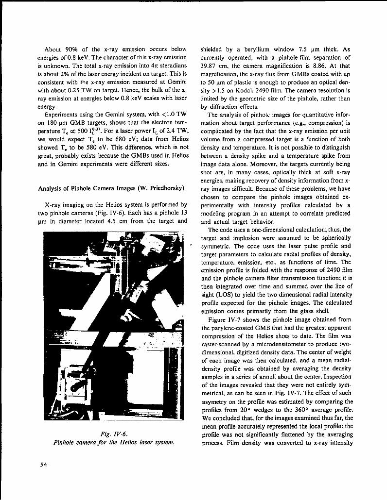
About 90V0 of the x-ray emission occurs beloi}
energies of 0.8 keV. The character of this x-ray emission
is unknown. The total x-ray emission into 47I steradians
is about 2’?40of the laser energy incident on target. This is
consistent with the x-ray emission measured at Gemini
with about 0.25 TW on target. Hence, the bulk of the x-
ray emission at energies below 0.8 keV scales with laser
energy.
Experiments using the Gemini system, with <1.0 TW
on 180-Lm GMB targets, shows that the electron tem-O.JTOFor a laser power IL of 2.4 TW,perature T, cc 500 IL
we would expect T, to be 680 eV; data from Helios
showed T, to be 580 eV. This difference, which is not
great, probably exists because the GMBs used in Helios
and in Gemini experiments were different sizes.
Analysis of Pinhole Camera Images (W. Priedhorsky)
X-ray imaging on the Helios system is performed by
two pinhole cameras (Fig. IV-6). Each has a pinhole 13
~m in diameter located 4.5 cm from the target and
.
Fig. IV-6.
Pinhole camera for the Helios laser system.
54
shielded by a beryllium window 7.5 ~m thick. As
currently operated, with a pinhole-film separation of
39.87 cm, the camera magnification is 8.86. At that
magnification, the x-ray flux from GMBs coated with up
to 50 ~m of plastic is enough to produce an optical den-
sity >1.5 on Kodak 2490 film. The camera resolution is
limited by the geometric size of the pinhole, rather than
by diffraction effects.
The analysis of pinhole imagek for quantitative infor-
mation about target performance (e.g., compression) is
complicated by the fact that the x-ray emission per unit
volume from a compressed target is a function of both
density and temperature. It is not possible to distinguish
between a density spike and a temperature spike from
image data alone. Moreover, the targets currently being
shot are, in many cases, optically thick at soft x-ray
energies, making recovery of density information from x-
ray images difficult. Because of these problems, we have
chosen to compare the pinhole images obtained ex-
perimentally with intensity profiles calculated by a
modeling program in an attempt to correlate predicted
and actual target behavior.
The code uses a one-dimensional calculation; thus, the
target and implosion were assumed to be spherically
symmetric. The code uses the laser pulse profile and
target parameters to calculate radial profiles of density,
temperature, emission, etc., as functions of time. Theemission profile is folded with the response of 2490 film
and the pinhole camera filter transmission function; it is
then integrated over time and summed over the line of
sight (LOS) to yield the two-dimensional radial intensity
profile expected for the pinhole images. The calculated
emission comes primarily from the glass shell.
Figure IV-7 shows the pinhole image obtained from
the parylene-coated GMB that had the greatest apparent
compression of the Helios shots to date. The film was
raster-scanned by a microdensitometer to produce two-
dimensional, digitized density data. The center of weight
of each image was then calculated, and a mean radial-
density profile was obtained by averaging the density
samples in a series of annuli about the center. Inspection
of the images revealed that they were not entirely sym-
metrical, as can be seen in Fig. IV-7. The effect of such
asymetry on the profde was estimated by comparing the
profiles from 20° wedges to the 360° average profile.
We concluded that, for the images examined thus far, the
mean profde accurately represented the local profde: the
profde was not significantly flattened by the averaging
process. Film density was converted to x-ray intensity
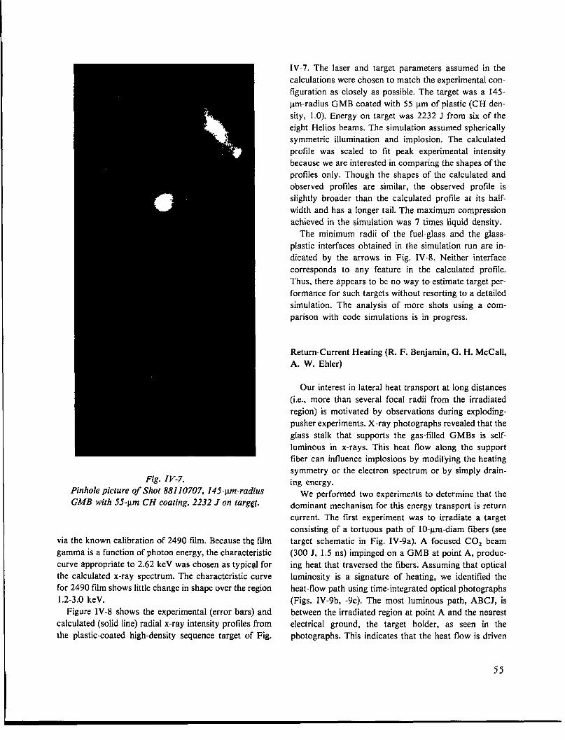
Fig. IV-7.Pinhole picture of Shot 88110707, 145-~ -raiiius
GA4B with 5.5-pm CH coating, 2232 J on targg~.
via the known calibration of 2490 film. Because the fdm
gamma is a function of photon energy, the characteristic
curve appropriate to 2.62 keV was chosen as typic~ for
the calculated x-ray spectrum. The characteristic curve
for 2490 film shows little change in shape over the region
1.2-3.0 keV.
Figure IV-8 shows the experimental (error bars) and
calculated (solid line) radial x-ray intensity profiles from
the plastic-coated high-density sequence target of Fig.
IV-7. The laser and target parameters assumed in the
calculations were chosen to match the experimental con-
figuration as closely as possible. The target was a 145-
~m-radius GMB coated with 55 ~m of plastic (CH den-
sity, 1.0). Energy on target was 2232 J from six of the
eight Helios beams. The simulation assumed spherically
symmetric illumination and implosion. The calculated
profile was scaled to tit peak experimental intensity
because we are interested in comparirlg the shapes of the
profiles only. Though the shapes of the calculated and
observed profiles are similar, the observed profile is
slightly broader than the calculated profile at its half-
width and has a longer tail. The maximum compression
achieved in the simulation was 7 times liquid density.
The minimum radii of the fuel-glass and the glass-
plastic interfaces obtained in the simulation run are in-
dicated by the arrows in Fig. IV-8. Neither interface
corresponds to any feature in the calculated profile.
Thus, there appears to be no way to estimate target per-
formance for such targets without resorting to a detailed
simulation. The analysis of more shots using a com-
parison with code simulations is in progress.
Return-Current Heating (R. F. Benjamin, G. H. McCall,
A. W. Ehler)
Our interest in lateral heat transport at long distances
(i.e., more than several focal radii from the irradiated
region) is motivated by observations during exploding-
pusher experiments. X-ray photographs revealed that the
glass stalk that supports the gas-filled GMBs is self-
luminous in x-rays. This heat flow along the support
fiber can influence implosions by modifying the heating
symmetry or the electron spectrum or by simply drain-
ing energy.
We performed two experiments to determine that the
dominant mechanism for this energy transport is return
current. The first experiment was to irradiate a target
consisting of a tortuous path of 10-~m-diam fibers (see
target schematic in Fig. IV-9a). A focused COZ beam
(300 J, 1.5 ns) impinged on a GMB at point A, produc-
ing heat that traversed the fibers. Assuming that optical
luminosity is a signature of heating, we identified the
heat-flow path using time-integrated optical photographs
(Figs. IV-9b, -9c). The most luminous path, ABCJ, is
between the irradiated region at point A and the nearest
electrical ground, the target holder, as seen in the
photographs. This indicates that the heat flow is driven
55
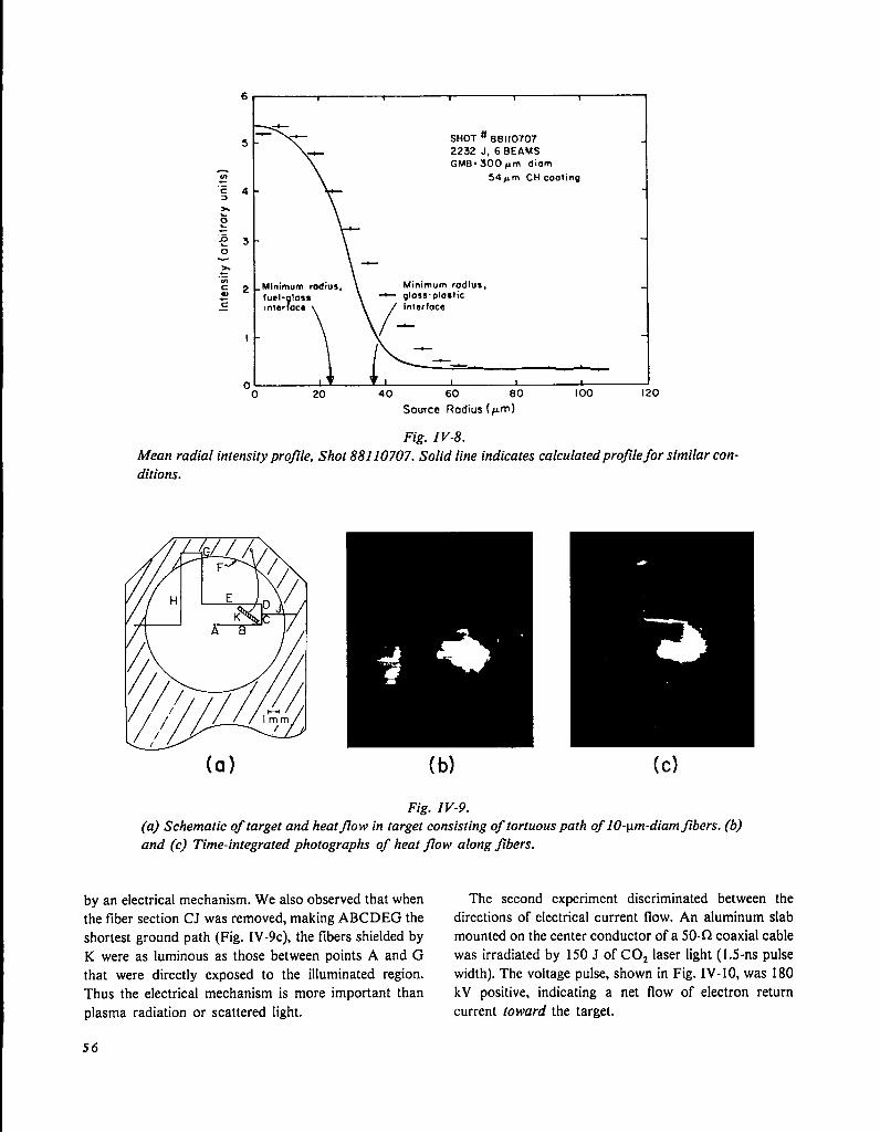
5 -2232 J, 6BEAMSGMB* 300pm diam
z 54pm CH caating.=c 4 -3
20.
.=nL 3 -0
h.=
:2 - Minimum radius,
fuel- loss?
* gloss .plos ticz— Inter ace
I
o 1
-o 2.0 40 60 80
Source Rodius (pm)
Fig. IV-8.Mean radial intensity profile, Shot 88110707. Solid line indicates
I 00 120
calculated profile for similar con-
(a) (b)
Fig. IV-9.
(a) Schematic of target and heatj70w in target consisting of tortuous path of 10-1.un-diamfibers. (b)
and (c) Time-integrated photographs of heat jlow along jlbers.
by an electrical mechanism. We also observed that when The second experiment discriminated between the
the fiber section CJ was removed, making ABCDEG the directions of electrical current flow. An aluminum slab
shortest ground path (Fig. IV-9 C), the fibers shielded by mounted on the center conductor of a 50-f2 coaxial cable
K were as luminous as those between points A and G was irradiated by 150 J of COZ laser light ( 1.5-ns pulse
that were directly exposed to the illuminated region. width). The voltage pulse, shown in Fig. IV-10, was 180
Thus the electrical mechanism is more important than kV positive, indicating a net flow of electron return
plasma radiation or scattered light. current toward the target.
56

r~180 kV
11 k-’’’--’ns
Fig. IV-10.
Positive voltage pulse indicating new jlow of current toward target.
We conclude that lateral heat transport at long dis-
tances along support fibers is driven by return current
that replenishes emitted hot electrons. The optical
luminosity is ohmic heating. A simple theoretical model
based on a Maxwellian electron distribution with a
measured temperature agrees with the value of the
voltage pulse and the number of emitted electrons. More
sophisticated current flow treatments must be implemen-
ted in computer simulations as a result of this
experiment.
DIAGNOSTIC DEVELOPMENT (R. P. Godwin)
Introduction
A viable laser fusion experimental program depends in
large part on being able to anticipate and develop the
kinds of instruments required. This is increasingly true
with large, complex laser facilities and ever more com-
plex targets.
During this reporting period, the researchers who
developed the invaluable fast charged-particle detectors
turned to the problem of improving the time resolution of
neutron detectors. Their objective is to improve our
ability to separate the effects of ion temperature, burn
time, and run-in time on neutron spectra.
We have continued our vigorous program of x-ray
diagnostics development with a balance of near-term
goals (such as the development of a PIN diode x-ray
spectrometer) and longer term goals (such as charge-
coupled imaging devices, which eventually should
replace film detectors). Our x-ray streak camera work
was plagued with triggering problems that were more dif-
ficult than we anticipated. Advances made during the
past six months, however, clarified the problems in this
area. In addition. we have a general project in the area of
fast high-voltage switching and triggering, which should
be useful for various diagnostics, including optical probe
beams and x-ray backlighting,
Although a superficial glance at 10.6-~m laser-plasma
interactions indicates that we should concentrate either
on infrared or x-ray photons, experience has shown that
visible-light imaging or spectroscopy provides important
information. Seeing is believing. Systematic development
of optical telephotography with high spatial resolution is
evolving from time-integrated photographs through tem-
porally resolved photography to the use of precisely
timed optical probe beams.
Ultrafast Neutron Diagnostics (T. H. Tan, A. Williams)
Recently, we developed several fast particle detectors
that can generate a signal pulse with a full width at half
maximum (FWHM) of 600 ps or less. Each detector is
assembled by coupling an ultrafast, quenched
scinti11ator]2 of some optimum size to a high-gain ITT
microchannel plate photomultipiier (MCP-PMT). A
typical assembly of the detector is shown in Fig. IV-11.
Figure IV- 12 shows the response of such a system. With
a fast GHz oscilloscope as recorder, it is possible to ob-
tain time resolution of less than 100 ps in time shift and
pulse broadening. This greatly extends our capability to
diagnose the performance of the high-compression laser
fusion targets.
For example, measurement of the implosion time from
the delay of the neutron arrival provides the first ex-
perimental clue of the hydrodynamic process associated
with laser fusion. With greater yield, the time history of
57
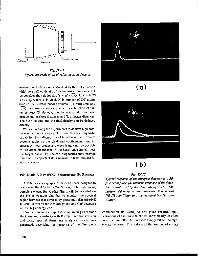
——-. —_
Fastsclnl,lw
I
///
IxEslLight guide
!.MCP
Photo
l--Anode
colhode
(a)
Fig. IV-11.
Typical assembly of an ultrafast neutron detector.
neutron production can be streaked by these electrons to
yield more refined details of the implosion processes. Let
us consider the relationship Y - nz <m> tc V = N2/V
<=v> t,, where Y is yield, N is number of DT atoms(known), V is instantaneous volume, t, is burn time, and
<~v> is cross-section rate, which is a function of fuel
temperature Ti alone; tC can be measured from pulse
broadening at short distances and TI at larger distances.
The burn volume and the final density can be deduced
directly.
We are pursuing the experiments to achieve high com-
pression at high enough yield to use this fast diagnostic
capability. Such diagnostics of laser fusion performance
become easier as the yield and confinement time in-
crease. At near breakeven, when it may not be possible
to use other diagnostics in the harsh environment near
the target, these fast neutron diagnostics may provide
much of the important data relevant to laser-induced fu-
sion processes.
PIN Diode X-Ray (PDX) Spectrometer (P. Roekett)
A PIN diode x-ray spectrometer has been designed to
operate in the 4.5- to 29.2-keV range. The instrument,
complete except for K-edge filters, will be mounted on
the Helios vacuum chamber to monitor the spectral
region between that covered by photomultiplier tube/NE
III scintillators on the low-energy end and CSF detectors
on the high-energy end.
Calculations were completed on optimizing PIN diode
thickness and sensitivity with K-edge filter transmission
and x-ray spectral form. An analytical mod61 was
generated, describing the response of the filter-diode
(b)Fig. IV-12.
Typical response of the ultrafast detector to a 50-
ps e-beam pulse. (a) Intrinsic response of the detec-
tor as calibrated by the Cerenkov light. (b) Com-
parison of detector response between 3% quenched
NE III scintillator and the standard NE III scin-
tillator.
combination (in C/mJ) to any given spectral input.
Variations of the diode thickness show clearly its effect
as a low-pass filter. A thin diode simply cut off the high-
energy response. This enhanced the amount of energy
58

of
.04
.02R(EI
.02
.0
0 J
tni = 10.4pm
t~i= 25pm
d~i =O.npm
-’K - band”
“Pass - bond”
J 1 I Y
10 20 30 40
E(keVl
Fig. IV-13.
Spectral sensitivity of j7[tered diode detector for
silicon depletion layer thickness t,i = 25 pm.
R[E)
tN=10.4pm
0.15 t~i = 250pm
d~i= o.8pm
0.1 - & “K - bond”
.05
n 1.10 20 30 40
El keW
Fig. IV-14.
Same as Fig. IV-13 for tli = 250 pm.
recorded in the K-edge region relative to that in the
higher energy pass-band. The dramatic effect of diode
thickness is illustrated in Figs. IV-13 and -14. Here, one
sees the spectral sensitivity of the faltered diode detectors
for two different silicon depletion layer thicknesses (t,).
The K-edge-detected energy constitutes the primary por-
tion of the total signal for t,i = 25 #m (Fig. IV-13), but
only a minor portion of the total signal for t~i = 250 ~m
(Fig. IV- 14). These design principles were used in choos-
ing both the diodes and filters for the PDX spectrometer.
X-Ray-Sensitive Charge-Coupled Device (CCD)
Development (P. Rockett)
A contract has been awarded to Westinghouse Cor-
poration for fabrication of an x-ray-sensitive (1-10 keV)
CCD ‘to replace film in x-ray pinhole cameras. The
proposed device will have a sensitive area 3 mm by 6
mm with 30-ym resolution at the detector and 2 x 10⁴
imaging pixels. It will be highly quantum-eflicient over
the entire range of 1-10 keV. Detailed high-resolution
images at 10 keV will enhance our insight into the source
of high-energy electrons in laser-induced plasmas. The
readout into our PDP 11/70 computer will be im-
mediate, allowing shot analysis on a real-time basis.
X-Ray Streak Camera Development (P. Rockett, J. S.
McGurn)
A streak camera mount for the Helios vacuum cham-
ber was designed and drawings were completed. The
mount provides tracks along which the camera may be
transported. An air lock allows the camera to be
removed from the chamber without breaking vacuum.
This will permit film to be reloaded without interfering
with experiments. Repositioning accuracy will be +10
~m with a remote station for motor control.
A pinhole translator was constructed for use with the
x-ray streak camera in an imaging mode. The position-
ing accuracy will be +2 ~m in 2-~m steps with both x-
and y-control. The translator will be attached to the
streak camera mounting rail independent of the camera.
The target, pinhole, and streak camera slit will be aligned
using a telescope of high magnification.
A new 36-stage, avalanche transistor trigger unit was
received from General Engineering and Applied Re-
search (GEAR) and was installed in the GEAR Pico-X
x-ray streak camera. This replaced the original fast
optical-spark-gap trigger, which could not be triggered
with 10.6-~m light. Tests indicated a sweep rate of 100
ps/mm.
We used our two-beam Nd:glass laser to determine
the transition trigger delay (by finding the x-ray streak in
time) and to calibrate the streak rate and linearity.
59

The laser provided a 300-ps FWHM, 1.06-~m pulse
to illuminate a 200-~m nickel microballoon. Two beams
were incident upon the target with 5 to 20 J per beam,
one beam delayed 1.5 ns with respect to the other. A
trigger beam was picked off and directed into a fast
photodiode. whose output then triggered the avalanche
stack in the Pico-X. Triggering delay, measured by os-
cilloscope, was 16 ns with <0.5 ns jitter when the unit
was fired into a 10-kCl, high-voltage probe.
When the camera was placed in the vacuum chamber,
however, the temporal location of the streak could not be
found. Occasional appearances of partial streak images
indicated that the avalanche stack did not function
properly and was randomly triggering on noise during
laser flashlamp discharge. Direct-current shots proved
that the streak tube was functioning and that sufilcient x-
ray flux was being generated for film exposure. Inspec-
tion of the trigger unit showed that many transistors
were being biased within a few volts of breakdown. The
camera is being relocated to our single-beam Nd:glass
laser (5 J, 30 ps) where the lower background noise level
is more suitable for further tests of delay, jitter, and
sweep rate.
Spectral calibration of the camera will continue at
4.93 keV (Ti Ka), and at or near 17.8 keV (Zr Ku).
These willprovidesixperformance data pointsand will
give us an accurate picture of the Pico-X spectral
sensitivity.
Integrated
,.-3
X-Ray Scaling Experiments (W. Priedhorsky, K.
Mitchell)
An investigation was made to determine whether x-
ray calorimetry could be performed using intensity
measurements of the Si resonance line ( ls2p – 1S2) to
determine absorbed laser energy on target.
Spectrometer and spectrograph data were obtained
from 50 shots with the south beam of the Gemini system
in and out of focus (to vary intensity) on a variety of
SiOz targets. Laser energy on target was varied through
nominal values of 50, 100, 200, and 300 J.
Figure IV- 15 shows the integrated signal in the Si
XIII resonance line ( 1s2p – 1S2) as a function of laser
energy. The upper line is the least-squares linear fit to the
focused shots on target (slab, lollipop, and GMB),
whereas the lower line is a fit of shots -360 ~m from
focus on glass slab targets. There is a notable difference
between the focused and unfocused shots: none of the
points from the unfocused shots falls above the mean
line of the focused shots.
The focused shots fit the relationship
= ~ 1.10 f 0.33lline L 3 I(IV-1)
, , 1 , , I 1 i { IJ&
1
FOCUSEOo
/
❑ +~11 A o # UNFOCUSEO
t
o 0 = 90pm GM8
O = LOLLI POP1
,C# ~10 100 1000
LASER ENERGY (J)
Fig. IV-15.
signal in the Si XIII resonance line (ls2p — 2s2) as a function of laser energy.
60
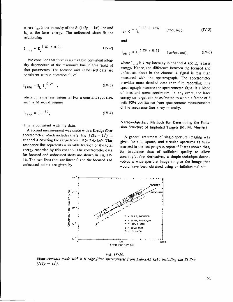
where I1ln~is the intensity of the Si ( 1s2p – 1S2) line and
EL is the laser energy. The unfocused shots fit the
relationship
= ~ 1.02 * 0.26lline L
(Iv-2)
We conclude that there is a small but consistent inten-
sity dependence of the resonance line in this range of
shot parameters. The focused and unfocused data are
consistent with a common fit
0.25lline ‘ELIL ‘
where IL is the laser intensity.
such a fitwould require
1.25lline = ‘L ‘
of
(Iv-3)
For a constant spot size,
(Iv-4)
This is consistent with the data.
A second measurement was made with a K-edge falter
spectrometer, which includes the Si line (ls2p – 1s2), in
channel 4 covering the range from 1.8 to 2.45 keV. This
resonance line represents a sizeable fraction of the total
energy recorded by this channel. The spectrometer data
for focused and unfocused shots are shown in Fig. IV-
16. The two lines that are linear fits to the focused and
unfocused points are given by
I ~ ~ 1.68 t 0.26ch4L
(focused)
and
(IV-5)
I = ~ 1.29 t 0.15ch4L (unfocused), (IV-6)
where IC~~ is x-ray intensity in channel 4 and EL is laser
energy. Hence, the difference between the focused and
unfocused shots in the channel 4 signal is less than
measured with the spectrograph. The spectrometer
provides more detailed data than film recording in a
spectrograph because the spectrometer signal is a blend
of lines and some continuum. In any event, the laser
energy on target can be estimated to within a factor of 2
with 9090 confidence from spectrometer measurements
of the resonance line x-ray intensity.
Narrow-Aperture Methods for Determining the Emis-
sion Structure of Imploded Targets (M. M. Mueller)
A general treatment of single-aperture imaging was
given for slit, square, and circular apertures as sum-
marized in the last progress report.13 It was shown that,
for irradiance data of sufficient quality to allow
meaningful first derivatives, a simple technique decon-
volves a wide-aperture image to give the image that
would have been obtained using an infinitesimal slit.
FOCUSED. i
+ ~ SLAB, f-360pm
~/’ A = 180pm GMB 3
0 = 90pm GMB
0 = LOLLIPOP1
lo-~~10 100 I 000
LASER ENERGY (J)
Fig. IV-16.Measurements made with a K-edge filter spectrometer from 1.80-2.45 keV, including the Si line
(Is2p – Is’).
61

Although the problem of instrumental broadening has
thus been overcome in principle, wide-aperture decon-
volution is often limited in practice because the data are
too noisy to yield useful first derivatives. Usually,
because of diffraction as well as limited source
radiances. very small apertures are also prohibited.
Thus, there is a need for methods to handle noisy data
taken with narrow apertures. Such methods, with par-
ticular reference to microballoon targets, are the subject
of this study. The numerical simulations were carried out
using a version of the code developed during the
previous study. *3
The two main questions to be addressed are:
● Can the base-intercept method be used to determine
the size of a small part of a radiating source? In
particular, can the diameter of an imploded core be
determined from its image, even though the image is
perturbed by the irradiance from the unimploded
microballoon wall? An ancillary issue is whether
the FWHM is a valid measure of the imfiloded core
diameter.
● Can a method be developed to determine the emit-
tance of the core relative to that of the imploded
wall from images formed by pinholes of narrow
aperture? This question bears directly on the issue
of inner-wall (pusher-fuel) stability during implo-
sion. If significant instability occurs, mixing of thewall material with the nearly nonradiant DT gas
would be expected to produce radiant cores without
much “hollowness” at the center. Conversely, a
core that is nearly nonradiant or “hollow” at the
center would indicate pusher-fuel hydrodynamic
fuel stability.
Figure IV- 17 is a microdensitometer trace through the
center of the time-integrated, x-ray pinhole image of an
imploded microballoon target (Shot VV29 ##4). It is a
good example of images obtained with the Gemini laser
system. They exhibit a dim outer ring having a diameter
approximately equal to that of the original microballoon,
and a brighter core about one-fourth the original
diameter. While some asymmetry in the core is usually
apparent. it will be ignored in this discussion.
Such time-integrated x-ray images may be interpreted
as being the superposition of two “snapshots’’-one of
the laser-heated microballoon wall before the implosion
has begun and the other of the compressed core at “turn-
around” before disassembly has begun. According to the
simulations, a model based on the superposition of these
snapshots is adequate to explain the measured image dis-
tributions. Thus, we tentatively conclude that the
remainder of the implosion history, when the glass shell
of reduced density moves at high speed, contributes only
a background irradiance to the time-integrated image.
However, a possibility remains that the core diameter
deduced from such photographs is appreciably larger
than the minimum core diameter attained.
The first question has been addressed by numerical
simulations using a variety of source emission models.
on so.rm plona M----o
——— ——-?05pm-—– ——
0.5 I .0 1.5 2.0 25 3.0 3.5
Displacement on Oetec?or Plone (mm)
Fig. IV-1 7.
Microdensitometer trace through the center of a time-integrated x-ray pinhole image
microballoon target imploded by the Gemini COZ laser system.of a
62

The conclusion is that the base-intercept method of
determining the core diameter is not only valid in the
normal range of experimental conditions, but is accurate
to one part in a thousand even when the emittance from
the unimploded shell is 30 times that from the imploded
core. Hence, we infer that the base-intercept method of
determining the sizes of “hot-spots” within a target is
amazingly robust against smooth but intense perturba-
tion from other parts of the source. Of course, the
method fails if the images of two or more hot-spots
overlap. The answer to the ancillary question is that the
FWHM is not generally a valid measure of the core
diameter, which is strongly dependent on core structure.
For example, for a homogeneous core, use of the
F WH M would result in overestimating the volume com-
pression by about a factor of 2.
The answer to the second question is more involved,
for we have developed two independent methods for
determining the x-ray emission from the central region of
an imploded microballoon. Both methods assume that
the absorption of the x-rays by the target is negligible, as
is reasonable for targets that have been used until now.
The first method is straightforward and potentially ac-
curate, even with data noise, but is tedious. It involves
assuming a source emission model, calculating the
radiance distribution, performing a two-dimensional con-
volution under the experimental configuration, and then
performing a second convolution under the conditions of
the microdensitometer scan. This procedure is then
iterated until the calculated irradiance pattern best tits
the data from the microdensitometer scan. Although this
method cannot provide a unique solution, our limited ex-
perience indicates that uniqueness is not a problem for
realistic source models.
An example of the modeling procedure will be given
without demonstrating the iterative process. The
parameter values have been chosen to give approximate
congruence with the data of Fig. IV- 17. The emission
model used is an outer (unimploded) shell of 180-~m o.d.
and an inner (imploded) shell of 45-~m o.d., with respec-
tive wall thicknesses of 1.8 and 5.6 ~m. The resulting
radiance pattern is then convolved with a 12-~m-diam
pinhole with a system magnification of 9, as shown in
Fig. IV- 18 in isometric projection. A microdensitometer
scan convolution using a 6.1 -~m-square aperture
(referred to the plane of the source) of this irradiance dis-
tribution is shown in Fig. IV-19. This second convolu-
tion partially fills in the central dip and broadens the
base intercepts, but leaves the FWHM of the core prac-
tically unchanged.
Fig. IV-18.
Irradiance distribution in the pinhole image of.the
emission model.
.9 -
.8 -
.7 -
2co .6 -.-U0&
.5 -a.g0 .4 -z
.3 -
.2 -
.1
Sourw Radws (pm)
Fig. IV-19.
Simulated microdensitometer scan through the
center of the irradiance distribution shown in Fig.
IV-18.
The main features of the simulated microdensitometer
scan in Fig. IV-19 are similar to those of Fig. IV-17. The
measured base intercept widths in Fig. IV-17 are
reduced by the standard method13 to give 185-Lm o.d.
for the unimploded shell and 45-~m o.d. for the imploded
shell. The microballoon target had a shell diameter of
180 Lm. It seems remarkable that such a simple source
model can give good congruence with a time-integrated
photograph. Many other simulations with varying
source models have been computed, and imply that the
63

data of Fig. IV-17 are consistent only with a model of
low central emission, which is consistent with the
hypothesis of pusher-fuel hydrodynamics stability.
When the model-adjusting method is used with a
rather narrow pinhole, the emission structure of the im-
ploded core can be determined accurately. However, it
can be time-consuming, so it would be desirable to have
a more expedient method to serve as a first diagnostic.
To this end, we have investigated the effectiveness of
the ratio of the FWHM of the core image to the core
diameter in determining the emission from the central
part of the core.
We found that the above ratio can indicate the relative
emission of the central region for a broad class of
realistic models. It appears that the FWHM could be
developed into a useful diagnostic of central core emis-
sion and that the FWHM method could be used with
larger apertures than those of the model-adjusting
method.
Reconstruction of Source Emission Structures from Slit
Images (M. M. Mueller)
The methods of source reconstruction discussed
above are integral methods that are generally superior
for noisy data, but they cannot guarantee a unique solu-
tion. For cases in which useful first derivatives can be
obtained, the derivative methods would be valuable as a
check on the uniqueness of integral methods, or as the
primary method, because they are suitable for automatic
calculation without human intervention. However, the
derivative methods require irradiance data from in-
finitesimal slits, which leaves only data from the wide-
aperture deconvolution method.13 Because wide-aperture
deconvolution is itself a differential method, its use to
provide input to other differential methods compounds
the requirement of low noise levels to impracticable
stringency. Hence, we are forced to consider the use of
differential methods on image data taken with practical
realizable slits.
Both available differential source-reconstruction
methods, a dual-sequential Abel inversion or the Vest
and Steel method, *4require radial source symmetry and
infinitesimal-slit images. However, the simpler Vest and
Steel method (dI/xdx, where I is the irradiance and x the
displacement) is the one to be discussed here. Our ques-
tion is whether we can use the Vest and Steel method
with undeconvolved irradiance data taken with practical,
narrow-slit apertures.
Although the answer depends somewhat on source
structure and the investigation is not completed, the Vest
and Steel method does not appear to work well with
practical apertures. The matter has been investigated
analytically for sources that give a uniform disk of
radiance and numerically for spherical-shell sources.
The conclusion is that appreciable source distortion
occurs for ratios of aperture width to overall target
diameter greater than -0.01. For aperture ratios as large
as 0.03, which is about the lower limit of practical,
diffraction-free slit imaging for larger targets, source
emission structure is rather grossly distorted. However,
the locations of emission structures are correctly pre-
served and the width of spherical shells can be roughly
determined by the naive application of the base-intercept
method, even though this method is strictly correct only
when applied to source diameters, not to shell widths.
Hence, the Vest and Steel method may be of some value
in source reconstruction from practical slit images even
though the emittance ratios between different parts of the
source may be badly distorted. Also, numerical simula-
tion could help in estimating the sense and magnitude of
the distortion, thus allowing correction.
The issue is complicated and is still under investiga-
tion. There is a possibility that a modified and elaborate
version of the Vest and Steel method could be devised to
give adequate source reconstruction from real data, but
it is clear that the straightforward application of this
method cannot give accurate emission ratios when prac-
tical slit widths are used.
Extension and Generalization of Two-Dimensional Im-
age Simulations (M. M. Mueller)
The convolution code13 developed to simulate single-
aperture images of randomly asymmetrical sources was
modified to provide more realistic simulations. One
modification replaces the circular or square aperture
with something intermediate: the generalized circle
(Uberkreis) x’ + y’= 1. At p = 2, the circular aperture
is recovered, while the square aperture is approached asp --+ ~. Because small “pinhole” apertures are never
really circular, a more general aperture shape for the
simulation is usually desirable, and in many cases con-
siderably improves the simulation accuracy.
Another modification improves the calculation of the
radiance from a three-dimensional source, which is
basically an Abel integral for cases of radial symmetry.
64
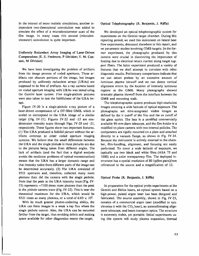
In the interest of more realistic simulations, another in-
dependent two-dimensional convolution was added to
simulate the effect of a microdensitometer scan of the
film image. In many cases this second (microden-
sitometer) convolution is quite important.
Uniformly Redundant Array Imaging of Laser-Driven
Compressions (E. E. Fenimore, P Division; T. M. Can-
non, M Division)
We have been investigating the problem of artifacts
from the image process of coded apertures. These ar-
tifacts can obscure portions of the image, but images
produced by uniformly redundant arrays (URAS) are
supposed to be free of artifacts. An x-ray camera based
on coded-aperture imaging with URAS was tested using
the Gemini laser system. Five single-pinhole pictures
were also taken to test the faithfulness of the URA im-
age.
Figure IV-20 is a single-pinhole x-ray picture of a
laser-driven compression of a DT-filled GMB, which is
scaled to correspond to the URA image of a similar
target (Fig. IV-2 1). Figures IV-22 and -23 are one-
dimension intensity scans through Figs. IV-20 and -21,
respectively. These figures show two important features.
(1) The URA produced a faithful picture without the ar-
tifacts common to other coded aperture imaging
systems. We believe that the small differences between
the URA and the single pinhole in these pictures are due
to the pictures being taken from different angles. The
lack of artifacts (and the fact that a digital analysis
avoids the nonlinear problems of optical reconstruction)
means that the URA has a larger dynamic range and
that intensity ratios from different parts of the image can
be determined accurately. (2) The URA consisted of
9521 apertures and, therefore, collected many more
photons than did the camera with the single pinhole.
Note that the peak in the URA intensity trace (Fig. IV-
23) represents -7100 times more photons than the peak
in the pinhole camera trace (Fig. IV-22). This is near the
theoretical maximum for the URA, which would be
9521 times as many photons, or a total of 6.60 x 10⁴.
With its much greater photon-collecting ability, the
URA can form images in a weak x-ray flux where the
single pinhole cannot. Also, the URA can be mounted
farther from the target, thus avoiding debris and making
space available for other diagnostics nearer the target.
Optical Telephotography (R. Benjamin, J. Riflle)
We developed an optical telephotographic system for
experiments on the Gemini target chamber. During this
reporting period, we used this instrument on lateral heat
flow experiments, discussed elsewhere in this report, and
on parametric studies involving GMB targets. In the for-
mer experiment, the photographs produced by this
camera were crucial in discovering the importance of
heating due to electrical return current along target sup-
port fibers. The latter experiment produced a variety of
features that we shall attempt to correlate with other
diagnostic results. Preliminary comparisons indicate that
we can detect prelase by an excessive amount of
luminous plasma blowoff and we can detect vertical
alignment errors by the location of intensely luminous
regions at the GMB. Many photographs showed
dramatic plasma blowoff from the interface between the
GMB and mounting stalk.
The telephotographic system produces high-resolution
images covering a wide latitude of optical exposure. The
photographs are time-integrated visible images as
defined by the ir cutoff of the film and the uv cutoff of
the glass optics. The lens is a modified commercially
available 90-mm-diam telescope, and the film holder is a
modified tri-plane camera with two internal pellicles. The
components are rigidly mounted on a plate and attached
directly to a vacuum flange, as shown in Fig. IV-24.
Because the instrument is entirely external to the cham-
ber, film-handling, alignment, and focusing are easily
performed. To cover a wide latitude of exposure, we
typically use two black and white fdms (ASA 75 and
1000) and a color transparency film. The deployed in-
strument has a spatial resolution of 801 p(live pairs)/mm
referenced to the source and a magnification of 12.
Optical Probe (R. Benjamin, J. Ritlle)
In preparation for the optical probe experiments at the
Gemini and Helios lasers, an optical system based on a
high-power, pulsed argon laser has been designed and
fabricated. The source assembly, shown in Fig. IV-25,
consists of a commercial argon laser (modified to syn-
chronize it with the COZ laser), an autocollimating align-
ment telescope, and beam transport optics. The structure
is extremely stable, yet portable. Initial experiments us-
ing this system will study plasma expansion, thermal
65
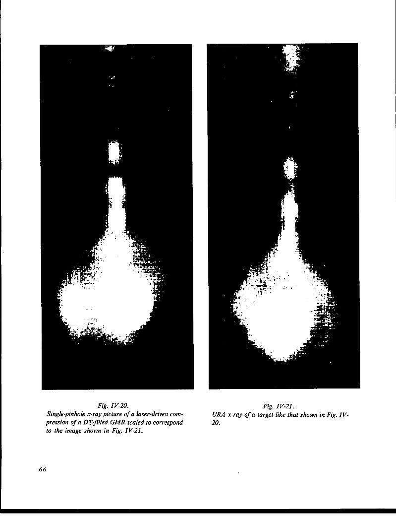
Fig. ZV-20.
Single-pinhole x-ray picture of a laser-driven com-
pression of a DT-@ed GMB scaled to correspond
to the image shown in Fig. IV-21.
66
Fig. IV-21.
URA x-ray of a target like that shown in Fig. IV-20.

693
100 pm
r
Fig. IV-22.
Densitometer trace of image in Fig. IV-20.
\.
1- 1100 pm
4.9 XI04
I
~
Fig. IV-23.Densitometer trace of image in Fig. IV-21.
Fig. IV-24.
Telephotography system consisting of a 90-mm-
diam telescope and a modt~ed tri-plane camera
used as a film holder. The assembly is rigidly
mounted on a plate attached to a vacuum flange.
PERFORATE MOVEAkSLEALIGNMENT MIRROR
ITARGET CHAMBER
SUPPORT STRUCTURE/
SYNCHRONOUS
TURNINGMIRROR
EXPANDER COLLIMATOR
PULSEO ARGON LASER
1’\ 1
IAUTOCOLLIMATING
ALIGNMENT SCOPE
TO TARGET
Fig. IV-25.Optical probe source assembly.
67

transport, and laser-driven shock propagation in
transparent media.
Incoherent, uv-Triggered Spark Gap (R. Carman, N.
Clabo, F. Wittman)
We are pioneering in the development of fast high-
vcsltage switching and triggering for use with various
diagnostics such as optical probe beams, x-ray and visi-
ble streak cameras, and x-ray backlighting.
A pressurized spark gap with low-interelectrode
capacitance was used in this investigation. A double-
electrode trigger was used with a uv-grade quartz tube to
isolate the trigger electrons from the main gap. Sul-
furhexafluoride (SF6) at 5 psi was mixed with argon at
400 psi to pressurize the spark gap. A 75-Mf2 charge
resistor was used in series with the spark gap and a 20-
kV pulse was used for the trigger. Peak outputs and
pulse widths for several different values of applied
voltage and spark-gap pressure are shown below. The
low-output peak with respect to applied voltage was at-
tributed to corona or leakage current from anode to
ground and to the cathode of the gap causing a large
voltage drop across the 75-MCI resistor. A new cavity is
being designed to withstand 2000 psi and have less
capacitance and a longer leakage path to ground. This
should allow us to use higher voltage, decrease pulse
width, and increase efficiency.
Voltage Appliedto PulseWidth
Charge Resistor Spark-Gap Pressure PeakOutput VoItage (FWHM)(kV) (psi) (v) (ns)
4 67 700 0.48
6 -110 1080 0.64
6 -125 -1000 0.60
> Vbrc,kd.-n -]25 800 0.64
High-Voltage, Short-Pulse Technology (F. Wittman, R.
Carman, N. Clabo)
We continued to develop technology to produce low-
jitter, fast-risetime, short electrical pulses of high-voltage
output. Several areas were explored, including the use of
overvoltage spark gaps to sharpen the pulse risetime,
the use of pulsed charging techniques for krytrons, and
the design of very low capacitance, electrically triggered
spark gaps for producing electrical pulses of <300 ps.
Also, several practical applications of this technology
were identified, one of which will be discussed in this
report.
Because laser-triggered spark gaps require careful
alignment and a large amount of maintenance, it would
be desirable to develop a simple, electrically triggered
krytron circuit that would produce a subnanosecond
output pulse of 15-20 kV. This could replace the op-
tically triggered spark gap used for pulse generators in
Pockels cell optical pulse selectors and pulse-clipping
systems. With this in mind, we attempted to understand
the process of pulsed charging of a krytron switch. We
found that KN22 krytrons (EG&G) were not useful in
this application because the pulsed charging process
caused them to trigger uncontrollably. Further, by ex-
ceeding the maximum anode applied voltage rating, it
was necessary to take into account the internal charac-
teristic 50-f2 impedance of the KN22, as well as the in-
creasing inductance of this impedance above 100 A. In
practice, a larger external load impedance was required
as the pulse charged voltage applied was increased.
The current capacity of the KN6B is -3000 A, and
the principal use is in -50-ns risetime applications,
therefore, we decided to try pulsed charging in this tube.
We found that while the dc applied voltage limit on the
KN6B anode was 8 kV, at least 20 kV could be applied
in a pulsed mode for up to -100 ns. Then, we noted that
if the applied voltage is pulsed to 50 or 60 kV, internal
conduction occurs. However, the resulting output pulse
from the KN6B can be very short. A pulse charging cir-
cuit was built using 10 series KN22B tubes to apply an
-60-kV pulse to the anode of one KN6B. No keep-alive
voltage is used on the KN6B so that full-charge voltage
is developed on the anode before the tube starts to con-
duct. Figure IV-26 shows a 519 (Tektronix) oscillogram
where the pulse is -900-ps FWHM with an 18.75-kV
peak. Notice that the trace does not return to the
baseline, but rather should be -5V0 of the peak due to
the steady-state discharge of the large anode capacitor
used in the KN22 string, while the output is taken into a
piece of 50-f2 coaxial cable. In many applications, this
feature is of no consequence, but when it is important, a
crowbar system could be used to eliminate it. The pulser
lifetime appears to be quite high, including the KN6B,
even though -375 A must flow to develop the full output
voltage. We are packaging one such pulser to use as a
pulse driver for a CdTe COZ pulse clipper. We intend to
pursue the answer to why 60 kV must be applied to the
68
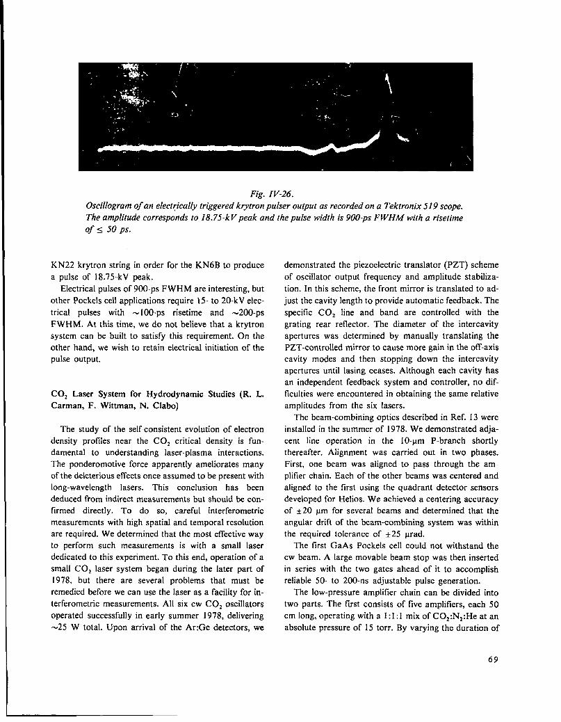
Fig. IV-26.
Oscillogram of an electrically triggered krytron pulser output as recorded on a Tektronix 519 scope.
The amplitude corresponds to 18.75-k Vpeak and the pulse width is 900-ps F WHA4 with a risetime
of < 50 ps.
KN22 krytron string in order for the KN6B to produce
a pulse of 18.75-kV peak.
Electrical pulses of 900-ps FWHM are interesting, but
other Pockels cell applications require 15- to 20-kV elec-
trical pulses with - 100-ps risetime and -200-ps
F WHM. At this time, we do not believe that a krytron
system can be built to satisfy this requirement. On the
other hand, we wish to retain electrical initiation of the
pulse output.
C02 Laser System for Hydrodynamic Studies (R. L.
Carman, F. Wittman, N. Clabo)
The study of the self-consistent evolution of electron
density profiles near the COZ critical density is fun-
damental to understanding laser-plasma interactions.
The ponderomotive force apparently ameliorates many
of the deleterious effects once assumed to be present with
long-wavelength lasers. This conclusion has been
deduced from indirect measurements but should be con-
firmed directly. To do so, careful interferometric
measurements with high spatial and temporal resolution
are required. We determined that the most effective way
to perform such measurements is with a small laser
dedicated to this experiment. To this end, operation of a
small COZ laser system began during the later part of
1978, but there are several problems that must be
remedied before we can use the laser as a facility for in-
terferometric measurements. All six cw C02 oscillators
operated successfully in early summer 1978, delivering
-25 W total. Upon arrival of the Ar:Ge detectors, we
demonstrated the piezoelectric translator (PZT) scheme
of oscillator output frequency and amplitude stabiliza-
tion. In this scheme, the front mirror is translated to ad-
just the cavity length to provide automatic feedback. The
specific C02 line and band are controlled with the
grating rear reflector. The diameter of the intercavity
apertures was determined by manually translating the
PZT-controlled mirror to cause more gain in the off-axis
cavity modes and then stopping down the intercavity
apertures until Iasing ceases. Although each cavity has
an independent feedback system and controller, no dif-
ficulties were encountered in obtaining the same relative
amplitudes from the six lasers.
The beam-combining optics described in Ref. 13 were
installed in the summer of 1978. We demonstrated adja-
cent line operation in the 10-~m P-branch shortly
thereafter. Alignment was carried out in two phases.
First, one beam was aligned to pass through the am-
plifier chain. Each of the other beams was centered and
aligned to the first using the quadrant detector sensors
developed for Helios. We achieved a centering accuracy
of +20 ym for several beams and determined that the
angular drift of the beam-combining system was within
the required tolerance of +25 ~rad.
The first GaAs Pockels cell could not withstand the
cw beam. A large movable beam stop was then inserted
in series with the two gates ahead of it to accomplish
reliable 50- to 200-ns adjustable pulse generation.
The low-pressure amplifier chain can be divided into
two parts. The first consists of five amplifiers, each 50
cm long, operating with a 1:1:1 mix of COz:Nz:He at an
absolute pressure of 15 torr. By varying the duration of
69
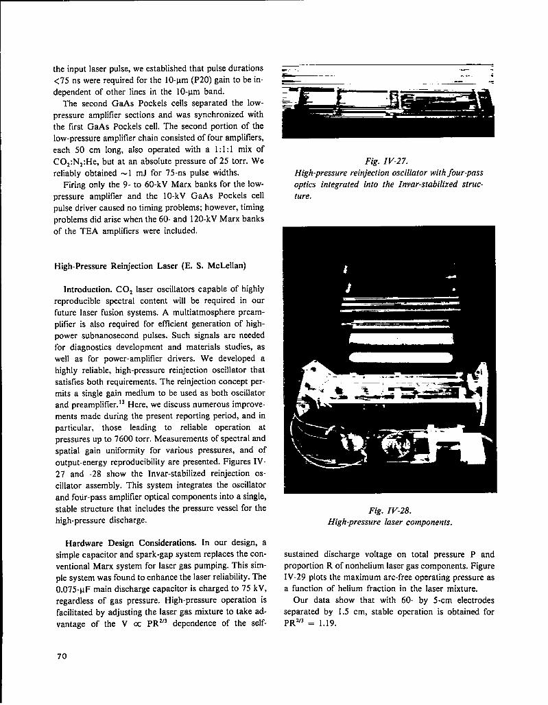
the input laser pulse, we established that pulse durations
<75 ns were required for the 10-vm (P20) gain to be in-
dependent of other lines in the 10-~m band.
The second GaAs Pockels cells separated the low-
pressure amplifier sections and was synchronized with
the first GaAs Pockels cell. The second portion of the
low-pressure amplifier chain consisted of four amplifiers,
each 50 cm long, also operated with a 1:1:1 mix of
COz:Nz:He, but at an absolute pressure of 25 torr. We
reliably obtained -1 mJ for 75-ns pulse widths.
Firing only the 9- to 60-kV Marx banks for the low-
pressure amplifier and the 10-kV GaAs Pockels cell
pulse driver caused no timing problems; however, timing
problems did arise when the 60- and 120-kV Marx banks
of the TEA amplifiers were included.
High-Pressure Reinfection Laser (E. S. McLellan)
Introduction. C02 laser oscillators capable of highly
reproducible spectral content will be required in our
future laser fusion systems. A multiatmosphere pream-
plifier is also required for etlicient generation of high-
power subnanosecond pulses. Such signals are needed
for diagnostics development and materials studies, as
well as for power-amplifier drivers. We developed a
highly reliable, high-pressure reinfection oscillator that
satisfies both requirements. The reinfection concept per-
mits a single gain medium to be used as both oscillator
and preamplifier. 13Here, we discuss numerous improve-
ments made during the present reporting period, and in
particular, those leading to reliable operation at
pressures up to 7600 torr. Measurements of spectral and
spatial gain uniformity for various pressures, and of
output-energy reproducibility are presented. Figures IV-
27 and -28 show the Invar-stabilized reinfection os-
cillator assembly. This system integrates the oscillator
and four-pass amplifier optical components into a single,
stable structure that includes the pressure vessel for the
high-pressure discharge.
Hardware Design Considerations. In our design, a
simple capacitor and spark-gap system replaces the con-
ventional Marx system for laser gas pumping. This sim-
ple system was found to enhance the laser reliability. The
0.075-vF main discharge capacitor is charged to 75 kV,
regardless of gas pressure. High-pressure operation is
facilitated by adjusting the laser gas mixture to take ad-‘3 dependence of the self-vantage of the V cc PR
~.-. ——--– -.-. =
—.— =
Fig. IV-27.
High-pressure reinfection oscillator with four-pass
optics integrated into the Invar-stabilized struc-
ture.
Fig. IV-28.High-pressure laser components.
sustained discharge voltage on total pressure P and
proportion R of nonhelium laser gas components. Figure
IV-29 plots the maximum arc-free operating pressure as
a function of helium fraction in the laser mixture.
Our data show that with 60- by 5-cm electrodes
separated by 1.5 cm, stable operation is obtained for
PRV3 = 1.19.
70
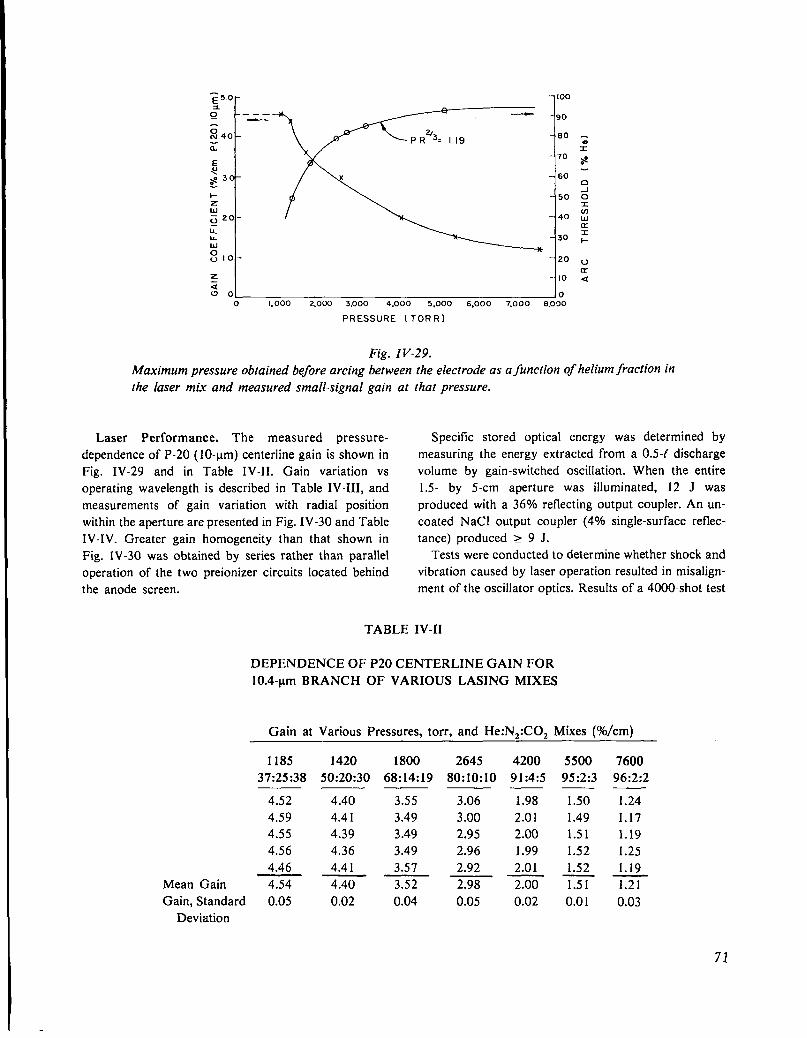
75.0- -1oo
xg .——
- 90
sN 40 – - 80
zzx
E- 70
~>0
a 30 —>– 60 :
1-Z
– 50 d
ux
~ 20 – – 40 :
LIY
II.w
– 30 :
0“lo - – 20 “
zLY
z– IO a
Uo o0 1,000 <003 3,000 4,000 5,000 6,000 7,000 8,000
PRESSURE [TORR)
Fig. IV-29.
Maximum pressure obtained before arcing bet ween the electrode as a function of helium fraction inthe laser mix and measured small-signal gain at
Laser Performance. The measured pressure-
dependence of P-20 (10-~m) centerline gain is shown in
Fig. IV-29 and in Table IV-II. Gain variation vs
operating wavelength is described in Table IV-III, and
measurements of gain variation with radial position
within the aperture are presented in Fig. IV-30 and Table
IV-IV. Greater gain homogeneity than that shown in
Fig. lV-30 was obtained by series rather than parallel
operation of the two preionizer circuits located behind
the anode screen.
TABLE
that pressure.
Specific stored optical energy was determined by
measuring the energy extracted from a 0.5-( discharge
volume by gain-switched oscillation. When the entire
1.5- by 5-cm aperture was illuminated, 12 J was
produced with a 36% reflecting output coupler. An un-
coated NaCl output coupler (4V0 single-surface reflec-
tance) produced 2 9 J.
Tests were conducted to determine whether shock and
vibration caused by laser operation resulted in misalign-
ment of the oscillator optics. Results of a 4000-shot test
IV-II
DEPENDENCE OF P20 CENTERLINE GAIN FOR
10.4-pm BRANCH OF VARIOUS LASING MIXES
Gain at Various Pressures, torr, and He: N.:CO, Mixes (%/cm)
1185
37:25:38
4.52
4.59
4.55
4.56
4.46
Mean Gain 4.54
Gain, Standard 0.05Deviation
1420
50:20:30
4.40
4.41
4.39
4.36
4.41
4.40
0.02
1800
68:14:19
2645
80:10:10
3.55
3.49
3.49
3.49
3.57
3.52
0.04
3.06
3.00
2.95
2.96
2.92
2.98
0.05
4200 5500
91:4:5 95:2:3— —
1.98 1.50
2.01 1.49
2.00 1.51
1.99 1.52
2.01 1.52
2.00 x
0.02 0.01
7600
96:2:2
1.24
1.17
1.19
1.25
1.19
1.21
0.03
71

TABLE IV-III
P- AND R-LINE DEPENDENCE OF GAIN AT CENTERLINE OF
67:14 :19:: He: N2:COz AT 1800 torr
Gain at 10.4-~m P-Lines (%/cm)
12 16 18 22 24—— ——
2.88 3.16 3.24 3.04 3.05
2.87 3.25 3.18 3.11 3.06
2.93 3.24 3.28 3.12 2.97
2.87 3.22 3.33 2.99 2.98
2.93 3.22 3.35 3.14 2.95
Main Gain ZT63T2ZT816FF0
Gain, Standard 0.03 0.03 0.07 0.06 0.05
Deviation
Gain at 10.4-ym R-Lines (Ye/cm)
14 16 18 20 22—— ——
2.85 2.95 2.93 2.75 2.61
2.84 2.91 2.93 2.79 2.63
2.87 2.94 2.94 2.73 2.62
2.90 2.99 2.97 2.75 2.60
2.93 2.97 2.95 2.76 2.60
Mean Gain %Z5=EZ
Gain, Standard 0.04 0.03 0.02 0.02 0.01
Deviation
Gain at 9.4-Mm R-Lines (’%o/cm)
CAVITY FOR
20 16 14 14 15 18 20—— —— —
3.18 3.34 3.14 2.93 3.10 3.18 3.21
3.17 3.31 3.38 2.92 3.10 3.12 3.20
3.19 3.26 3.37 2.92 3.11 3.11 3.20
3.23 3.30 3.36 2.98 3.22 3.21 3.19
3.14 3.23 3.39 3.02 3.07 3.15 3.21
Main Gain 3.18~~8~5~~ ~
Gain, Standard 0.03 0.05 0.02 0.04 0.06 0.04 0.01
Deviation
conducted during a 6-day period are shown in Fig. IV- charge and optical structure in this design did not
31. No drop in laser energy was observed after 4000 degrade system reliability.
shots within the 1Voresolution of the measuring system. During this test, there were 6 shot failures in a 4000
These results show that mechanical coupling of the dis- shot sequence. This 99.85% reliability was obtained
72
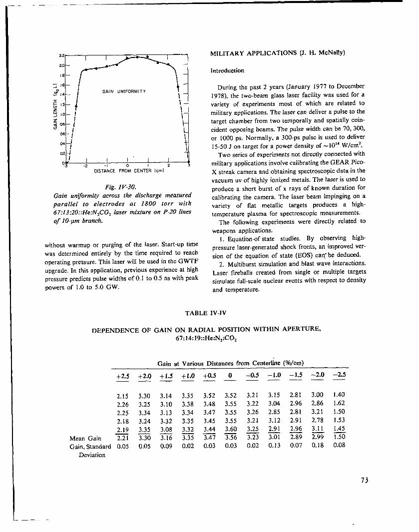
22I I
20—
1.8—
~ 16 —
2° I.4 —l–
;\\
i
II
;~,,,,if
-3 -2 -1 0
DISTANCE FROM CENTER (cm)
Fig. w--m.Gain unformity across lhe discharge measured
parallel to electrodes at 1800 torr with
67:13 :20::He:NzCOz laser mixture on P-IO tines
of 10-pm branch.
without warmup or purging of the [aser. Start-up time
was determined entirely by the time required to reach
operating pressure. This laser will be used in the GWTF
upgrade. In this application, previous experience at high
pressure predicts pulse widths of 0.1 to 0.5 ns with peak
powers of 1.0 to 5.0 GW.
MILITARY APPLICATIONS (J. H. McNally)
Int reduction
During the past 2 years (January 1977 to December
1978), the two-beam glass laser facility was used for a
variety of experiments most of which are related to
military applications. The laser can deliver a pulse to the
target chamber from two temporally and spatially coin-
cident opposing beams. The pulse width can be 70, 300,
or 1000 ps. Normally, a 300-Ps pulse is used to deliver
15-50 J on target for a power density of -1014 W/cm*.
Two series of experiments not directly connected with
military applications involve calibrating the GEAR Pico-
X streak camera and obtaining spectroscopic data in the
vacuum uv of highly ionized metals. The laser is used to
produce a short burst of x rays of known duration for
calibrating the camera. The laser beam impinging on a
variety of flat metallic targets produces a high-
temperature plasma for spectroscopic measurements.
The following experiments were directly related to
weapons applications.
1. Equation-of-state studies. By observing high-
-pressure laser-generated shock fronts, an improved ver-
sion of the equation of state (EOS) can.- be deduced.
2. Multiburst simulation and blast wave interactions.
Laser fireballs created from single or multiple targets
simulate full-scale nuclear events with respect to density
and temperature.
TABLE IV-IV
DEPENDENCE OF GAIN ON RADIAL POSITION
67:14 :19::He:N2:C0,
Gain at Various Distances from
WITHIN APERTURE,
Centerline (%/cm)
+2.5 +2.0 +1.5 +1.0 +0.5 O –0.5 –1.0 –1.5 –2.0 –2.5—. .— — —. —— —.
2.15 3.30 3.14 3.35 3.52 3.52 3.21 3.15 2.81 3.00 1.40
2.26 3.25 3.10 3.38 3.48 3.55 3.22 3.04 2.96 2,86 1.62
2.25 3.34 3.13 3.34 3.47 3.55 3.26 2.85 2.81 3.21 1.50
2.18 3.24 3.32 3.35 3.45 3.55 3.21 3.12 2.91 2.78 1.53
2.19 3.35 3.08 3.32 3.44 3.60 3.25 2.91 2.96 3.11 1.45
Mean Gain z no m 5% -m =6 E= m m 3
Gain, Standard 0.05 0.05 0.09 0.02 0.03 0.03 0.02 0.13 0.07 0.18 0.08Deviation
73
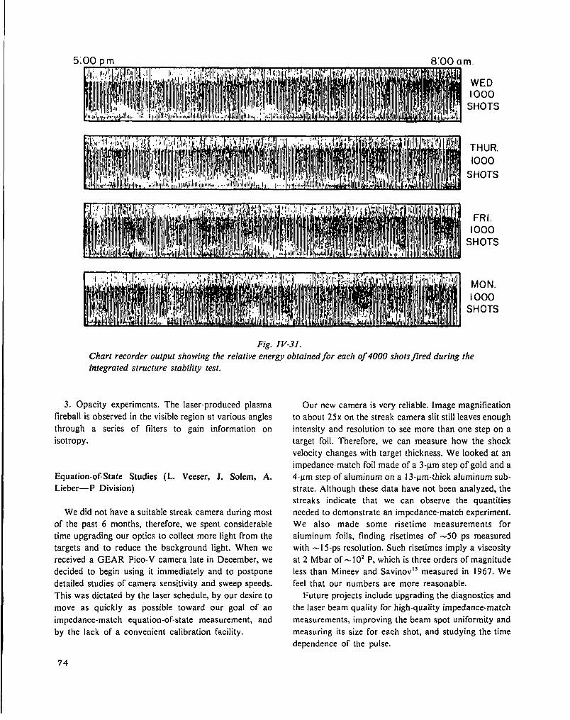
5:00 pm 8:00 am
WEDI000
SHOTS
THUR.
1000
SHOTS
FRI.1000
SHOTS
MON.I 000
SHOTS
Chart recorder output showing the relative energy obtained for each of 4000 shots fired during the
integrated structure stability test.
3. Opacity experiments. The laser-produced plasma
fireball is observed in the visible region at various angles
through a series of filters to gain information on
isotropy.
Equation-of-State Studies (L. Veeser, J. Solem, A.
Lieber—P Division)
We did not have a suitable streak camera during most
of the past 6 months, therefore, we spent considerable
time upgrading our optics to collect more light from the
targets and to reduce the background light. When we
received a GEAR Pico-V camera late in December, we
decided to begin using it immediately and to postpone
detailed studies of camera sensitivity and sweep speeds.
This was dictated by the laser schedule, by our desire to
move as quickly as possible toward our goal of an
impedance-match equation-of-state measurement, and
by the lack of a convenient calibration facility.
Our new camera is very reliable. Image magnification
to about 25x on the streak camera slit still leaves enough
intensity and resolution to see more than one step on a
target foil. Therefore, we can measure how the shock
velocity changes with target thickness. We looked at an
impedance-match foil made of a 3-Lm step of gold and a
4-~m step of aluminum on a 13-~m-thick aluminum sub-
strate. Although these data have not been analyzed, the
streaks indicate that we can observe the quantities
needed to demonstrate an impedance-match experiment.
We also made some risetime measurements for
aluminum foils, finding risetimes of -50 ps measured
with - 15-ps resolution. Such risetimes imply a viscosity
at 2 Mbar of- 102 P, which is three orders of magnitude
less than Mineev and Savinovls measured in 1967. We
feel that our numbers are more reasonable.
Future projects include upgrading the diagnostics and
the laser beam quality for high-quality impedance-match
measurements, improving the beam spot uniformity and
measuring its size for each shot, and studying the time
dependence of the pulse.
74
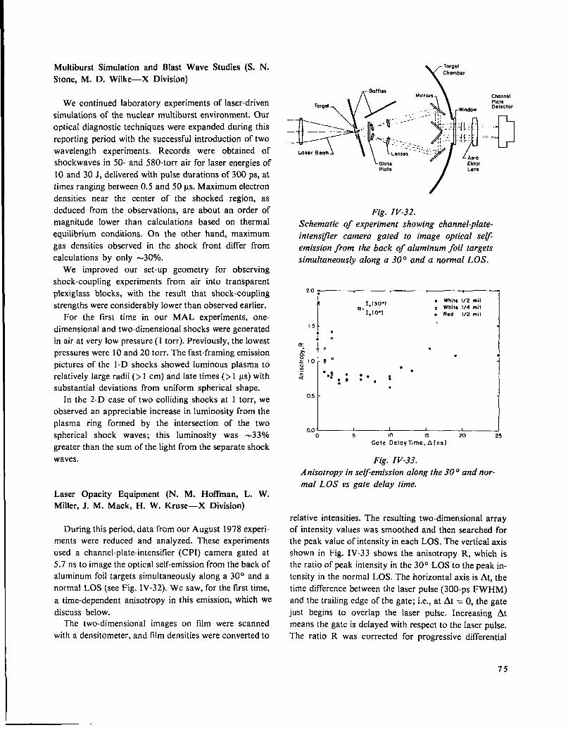
Multiburst Simulation and Blast Wave Studies (S. N.
Stone, M. D. Wilke—X Division) YTar@Chamber
We continued laboratory experiments of laser-driven
simulations of the nuclear multiburst environment. Our
optical diagnostic techniques were expanded during this
reporting period with the successful introduction of two
wavelength experiments. Records were obtained of
shockwaves in 50- and 580-torr air for laser energies of
10 and 30 J, delivered with pulse durations of 300 ps, at
times ranging between 0.5 and 50 us. Maximum electron
densities near the center of the shocked region, as
deduced from the observations, are about an order of
magnitude lower than calculations based on thermal
equilibrium conditions. On the other hand, maximum
gas densities observed in the shock front differ from
calculations by only -30V0.
We improved our set-up geometry for observing
shock-coupling experiments from air into transparent
plexiglass blocks, with the result that shock-coupling
strengths were considerably lower than observed earlier.
For the first time in our MAL experiments, one-
dimensional and two-dimensional shocks were generated
in air at very low pressure ( 1 torr). Previously, the lowest
pressures were 10 and 20 torr. The fast-framing emission
pictures of the 1-D shocks showed luminous plasma to
relatively large radii (> 1 cm) and late times (> 1 us) with
substantial deviations from uniform spherical shape.
In the 2-D case of two colliding shocks at I torr, we
observed an appreciable increase in luminosity from the
plasma ring formed by the intersection of the two
spherical shock waves; this luminosity was -330/0
greater than the sum of the light from the separate shock
waves.
Baffla$
\!&
)
Mwrors
i
Channel
TargaIPlateOeleclor. . . .
. .. . .. . .
=I:i=+fy;;;::=:,:$:: ~“....:~
Glass EklorPlate Lam
Fig. IV-32.
Schematic of experiment showing channel-plate-
intensljler camera gated to image optical self
emission from the back of aluminum foil targets
simultaneously along a 300 and a normal LOS.
2.0.
I1“[30”)
. Whit@ 1/2 mil
I
o While 1/4 mil“ 1,[0”) o Red 1/2 mil
(Y I:“” .
:
I
.1.0 8 “0. ●.-
“.: ..*.
s .**, t. .
0.5t
II
0,0 ~o 5 In Is 20
Gafe Delay ~me, A(ns)
Fig. IV-33.
A nisotropy in se~-emission along the300 and nor-
mal LOS vs gate delay time.Laser Opacity Equipment (N. M. Hoffman, L. W.
Miller, J. M. Mack, H. W. Kruse—X Division)
During this period, data from our August 1978 experi-
ments were reduced and analyzed. These experiments
used a channel-plate-intensifier (C PI) camera gated at
5.7 ns to image the optical self-emission from the back of
aluminum foil targets simultaneously along a 30° and a
normal LOS (see Fig. IV-32). We saw, for the first time,
a time-dependent anisotropy in this emission, which we
discuss below.The two-dimensional images on film were scanned
with a densitometer, and film densities were converted to
relative intensities. The resulting two-dimensional array
of intensity values was smoothed and then searched for
the peak value of intensity in each LOS. The vertical axis
shown in Fig. IV-33 shows the anisotropy R, which is
the ratio of peak intensity in the 30° LOS to the peak in-
tensity in the normal LOS. The horizontal axis is At, the
time difference between the laser pulse (300-ps FWHM)
and the trailing edge of the gate; i.e., at At = O, the gate
ju%t begins to overlap the laser pulse. Increasing At
means the gate is delayed with respect to the laser pulse.
The ratio R was corrected for progressive differential
75

obscuration of the glass plate protecting the optics; this
effect is always < 12Y0. Each point represents a single
laser shot; pulse energies range between 9 and 40 J.
Most of the data in Fig. IV-33 are for an unfiltered
band of white light, defined essentially by the S-20
response of the CPI photocathode. However, 3 points
were taken using a red filter which passed only k >6000
A. These points are shown as open circles.
These data reveal a trend from “limb-brightening” (R
> I) to “limb-darkening” (R < 1) as the gate is delayedwith respect to the laser pulse. At late enough times (At
> 10 ns), R returns roughly to unity. The l/4-roil foils
behave much like the l/2-mil foils, although we have lit-
tle data for them. Interestingly, red light seems to be
“limb-brightened” at the same time that white light is
“limb-darkened” at At = 2 ns.
Figure IV-34 shows relative intensity in the normal
LOS vs gate delay time for laser pulses with energies be-
tween 26 and 31 J striking l/2-roil foils. This profile is
what one expects from smearing the true intensity
history of the target backside with the -6-ns FWHM
gate: from earlier streak camera observations we know
that the intensity history consists of a bright flash of< 1-
ns duration, followed by a fainter tail of > 10-ns dura-
tion.
Comparing Fig. IV-33 with Fig. IV-34 shows that the
limb-darkening (R m 0.75 at 2 ns s At s 10 ns) is
associated with the smeared-out bright flash. Also, the
return of R to roughly unity is associated with the faint
tail at At 2 10 ns. This is expected as the plasma
.
.“
26 JsCS31J
While, 1/2 mil Al
.
●
✎
✎
✎✎☛
●●
✎
t i5 10 IS 20 25
Gale Delay Time, Al(ns)
Fig. IV-34.
Relative intensity in the normal LOS vs gate delay
time.
76
becomes nonplanar, which certainly occurs by 10 ns af-
ter the laser pulse.
The limb-brightening for At < 2 ns has been a
mystery, though we now believe it may be an instrumen-
tation effect. We can rule out a straightforward inter-
pretation using any isotropic source function in a planar
plasma; it is impossible to get limb-brightening stronger
than l/cos O in this way. At (3 = 30°, l/cos 0 = 1.15,
whereas we have R between 1.5 and 2.0.
Thus, we are led to consider a dynamic instrumenta-
tion effect as a source of spurious limb-brightening. Sup-
pose that the CPI tube does not gate simultaneously
across its surface. Specifically, suppose that the portion
of the tube viewing the 30° LOS gates “off” slightly later
than the portion of the tube in the normal LOS. Then for
At = O, the 30° view will integrate more of the rising
edge of the bright flash than will the normal view, giving
a spurious limb-brightening. If this does happen, and it
probably does (see below), it nevertheless does not in-
validate our observations of limb-darkening.
If the back-side emission were not intrinsically limb-
darkened, then the spurious limb-brightening caused by
nonsimultaneous gating would persist at least until the
leading edge of the gate is moved later than the laser
pulse: i.e., until At N 6 ns. After At m 6 ns, it might be
possible for nonsimultaneous gating to give spurious
limb-darkening; then the emission intensity is decreasing
with time over most of the gate duration. This argument
does not affect the limb-darkening for 2 ns s At <6 ns,
except possibly to make the observed limb-darkening
somewhat weaker than the intrinsic limb-darkening.
Recent experiments show that, in fact, the CPI tube
does not gate simultaneously across its surface. It ap-
pears that the outer edge of the circular tube gates “on”
about I ns before the center of the tube; the edge gates
“off’ slightly earlier, too, so that the total gate duration
is about the same across the tube. The gating pattern is
circularly symmetric about the center of the tube; thus,
to remove this effect one could simply ensure that the
two target images are equidistant from the tube center.
We are reviewing the data to determine how far the two
images were from being centered.
Vacuum uv Spectroscopy of Highly-ionized Metals (J.
Reader and G. Luther, NBS, Washington, DC)
In October 1978, researchers from the National
Bureau of Standards used LASL’S high-power Nd:glass
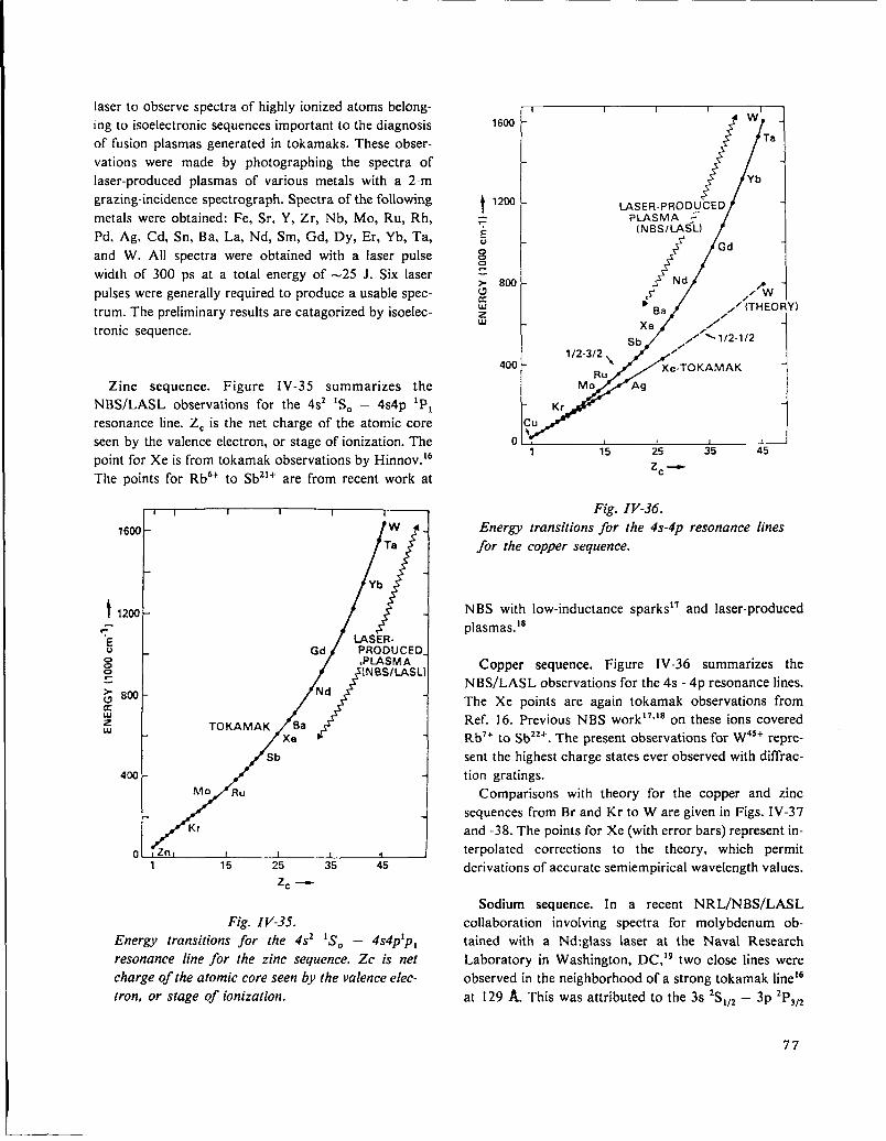
laser to observe spectra of highly ionized atoms belong-
ing to isoelectronic sequences important to the diagnosis
of fusion plasmas generated in tokamaks. These obser-
vations were made by photographing the spectra of
laser-produced plasmas of various metals with a 2-m
grazing-incidence spectrograph. Spectra of the following
metals were obtained: Fe, Sr, Y, Zr, Nb, Mo, Ru, Rh,
Pd, Ag, Cd, Sn, Ba, La, Nd, Sm, Cd, I)y, Er, Yb, Ta,
and W. All spectra were obtained with a laser pulse
width of 300 ps at a total energy of -25 J. Six laser
pulses were generally required to produce a usable spec-
trum. The preliminary results are categorized by isoelec-
tronic sequence.
Zinc sequence. Figure IV-35 summarizes the
NBS/LASL observations for the 4s2 lSO – 4s4p lP,
resonance line. ZC is the net charge of the atomic core
seen by the valence electron, or stage of ionization. The
point for Xe is from tokamak observations by Hinnov.16
The points for Rb6+ to Sb21+ are from recent work at
1 ( 1 I 1 r *
1600 -
t 1200--~c
‘/’’(,;Sb
400
MO R“
Kr
o Zn1 15 25 35 45
z= -
Fig. IV-35.
Energy transitions for the 4s2 lSO – 4s4plp,resonance line for the zinc sequence. Zc is net
charge of the atomic core seen by the valence elec-
tron, or stage of ionization.
,.~~
t 1200 - LASER. PRODUCE
~ PLASMA ~“
E (N BS/LASL)o
000
> 800 -a ,<”5z Ba ,’ (THEORYIw
Sb112-312 \
400 -RU
Mo
o , I 1 , J1 15 25 35 45
z=*
Fig. IV-36.
Energy transitions for the 4s-4p resonance lines
for the copper sequence.
NBS with
plasmas.]8
Copper
low-inductance sparksl’ and laser-produced
sequence. Figure IV-36 summarizes the
NBS/LASL observations for the 4s - 4p resonance lines.
The Xe points are again tokamak observations from
Ref. 16. Previous NBS work]7’18 on these ions covered
Rb7+ to Sbz2~. The present observations for W45+ repre-
sent the highest charge states ever observed with diffrac-
tion gratings.
Comparisons with theory for the copper and zinc
sequences from Br and Kr to W are given in Figs. IV-37
and -38. The points for Xe (with error bars) represent in-
terpolated corrections to the theory, which permit
derivations of accurate semiempirical wavelength values.
Sodium sequence. In a recent NRL/NBS/LASL
collaboration involving spectra for molybdenum ob-
tained with a Nd:glass laser at the Naval Research
Laboratory in Washington, DC,]9 two close lines were
observed in the neighborhood of a strong tokamak line16
at 129 A. This was attributedto the 3s 2S1,2– 3p 2P3,2
77
——
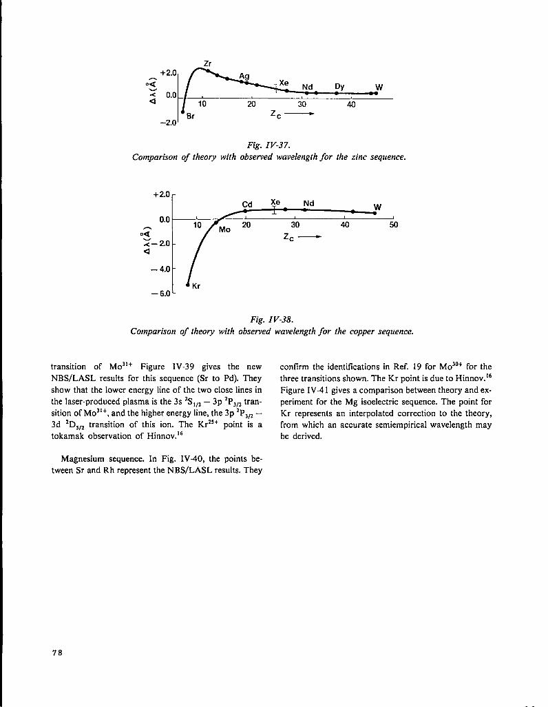
Fig. IV-37.
Comparison of theory with observed wavelength for the zinc sequence.
+ 2.0r-
0.0 ;0 1
n 30 40 500< z= —z- 2.0-4
-4.0M
Fig. IV-38.
Comparison of theory with observed wavelength for the copper sequence.
transition of MC131+ Figure IV-39 gives the new confirm the identifications in Ref. 19 for Mo 30+ for the
NBS/LASL results for this sequence (Sr to Pal). They three transitions shown. The Kr point is due to Hinnov.16
show that the lower energy line of the two close lines in Figure IV-4 1 gives a comparison between theory and ex-the laser-produced plasma is the 3s ‘Sllz – 3p 2PJJZtran- periment for the Mg isoelectric sequence. The point for
sition of M031+, and the higher energy line, the 3p 2P~12— Kr represents an interpolated correction to the theory,3dZD .-
~JZtransition of this ion. The Kr2s+ point is a from which an accurate semiempirical wavelength may
tokamak observation of Hinnov.lG be derived.
Magnesium sequence. In Fig. IV-40, the points be-
tween Sr and Rh represent the NBS/LASL results. They
78

1000
!
800
TE 6000000
: 400C5a
2
u 200
[ K, 1 1 t I10 15 20 25 30 3k—
zc—
Fig. IV40.Energy transitions for the magnesium isoelectronic
sequence showing three transitions of Mo30+.+>uK
:w
Fig. IV-39.Energv transitions for the sodium isoelectronic
sequence showing two transitions of A4031+.
1000 -
600 -3s 3p 3P2 —3s3d3D
TE 3s 3p ‘Pl —3s3d ‘D2u 600 -0 Kr-TOKAMAKo0
400 -
200 -
1 K 1 1 1 ~~~10 15 20 25 30 35
Zc —
Fe0.30
0.20
1~
Ni
.= 0.10 ,5 Ga25 31
G0.00 — -–—
–0.10 zc—Mo
Fill
-0.20 Se Sr
– 0.30 L Kr
Fig. IV-41.Comparison of theory with experiment for transition wavelengths in the magnesium isoelectronicsequence.
79

REFERENCES
1,
2.
3.
4.
5.
6.
7.
8.
9.
80
D. B. vanHulsteyn, P. Lee, K. B. Mitchell, and P. D.
Rockett, “X-Ray Continuum Spectra,” in “Laser
Fusion Program, July 1—December 31, 1977,” Los
Alamos Scientific Laboratory report LA-7328-PR
(December 1978).
D. Giovanielli and C. W. Cranfill, “Simple Model
for Exploding Pusher Targets,” Los Alamos Scien-
tific Laboratory report LA-72 18-MS (May 1978).
V. Cottles, D. Giovanielli, L. White, and A.
Williams, “Absorption Measurements- 10.6 ~m COZ
Laser Light,” in “Laser Fusion Program, July
1—December 31, 1977,” Los Alamos Scientific
Laboratory report LA-7328-PR (December 1978).
F. Young, “Thomson Parabola Measurement of
Fast-Ion Spectra and Population of Ion-Charge
States,” in “Laser Fusion Program, July l—Decem-
ber 31, 1977,” Los Alamos Scientific Laboratory
report LA-7328-PR (December 1978).
D. Giovanielli, J. Kephart, and A. H. Williams,“Spectra and Angular Distributions of Electrons
Emitted from Laser-Produced Plasmas” J. Appl.
Phys. 47, 2907 (1976).
R. F. Benjamin, G. H. McCall, and A. Wayne
Ehler, “Measurement of Return Current in a Laser-
Produced Plasma;’ Phys. Rev. Lett. 42,890 (1979).
T. H. Tal, “Inertial Fusion Program, January l—
June 30, 1978,” Los Alamos Scientific Laboratory
report LA-7587-PR (May 1980).
J. G. Crow, J. Plasma Phys. 14, Part 1, 65 (1975).
D. Forslund, J. M. Kindel, and K. Lee, Phys. Rev.
Lett. 39, 284 (1977).
10.
11
12.
13.
14.
V. Cottles, “Inertial Fusion Program, January
l—June 30, 1978,” Los Alamos Scientific
Laboratory report LA-7587-PR (May 1980).
T. H. Tan, “Inertial Fusion Program, January l—
June 30, 1978,” Los Alamos Scientific Laboratory
report LA-7587-PR (May 1980).
P. B. Lyons, S. E. Caldwell, L. P. Hocker, D. G.
Crandall, P. A. Zaganiro, J. Cheng, G. Tirsell, and
C. R. Hurlbert, IEEE Trans. Nucl. Sci. NS-24
(1977) p. 177.
F. Skoberne, Comp., “Inertial Fusion Program,
January 1—June 30, 1978,” Los Alamos Scientific
Laboratory report LA-7587-PR (May 1980).
C. M. Vest and D. G. Steel, “Reconstruction of
Spherically Symmetric Objects from Slit-Imaged
Emission: Application to Spatially Resolved Spec-
troscopy,” Opt. Lett. 3, 54-6, (1978).
15. V. N. Mineev and E. V. Savinov, Sov. Phys. JETP
52, 629 (1967).
16. E. Hinnov, ‘*Highly Ionized Atoms in Tokamak
Discharges,” Phys. Rev. 14A, 1533 (1976).
17. J. Reader and N. Acquista, “4s-4p Resonance Tran-
sitions in Highly Ionized Cu- and Zn-like Ions,”
Phys. Rev. Lett. 39, 184 (1977).
18. J. Reader, G. Luther, and N. Acquista, “Spectrum
and Energy Levels of Thirteen-Times Ionized
Molybdenum (Mo XIV);’ J. Opt. Sot. Am. (Decem-
ber 1978).
19. P. G. Burkhalter, J. Reader, and R. D. Cowan
“Spectra of Mo XXX, XXXI and XXXII from a
Laser-Produced Plasma,” J. Opt. Sot. Am. 67, 1521
(1977).

V. LASER FUSION THEORY AND TARGET DESIGN
(D. B. Henderson)
Our theoretical support activities are closely coupled to our experimental efforts, with
the intent of gaining a fundamental understanding of laser-target interactions, par-
ticularly of the relevant plasma physics and hydrodynamics. The close coupling of
theory and experiments has made it possible to eliiinate theories that are not supported
by experiment. In general, basic studies have shown that the design difficulties as-
sociated with long wavelength are less severe than believed earlier, and that breakeven
target designs are attainable even in the presence of a hot-electron spectrum. These
results have increased our confidence that scientific breakeven can be demonstrated
with our efficient, inexpensive C02 lasers.
THEORETICAL SUPPORT
Introduction (D. W. Forslund)
The supporting physics section continued its efforts to
develop models for laser light absorption and transport
of the resulting deposited energy. The effects of
deliberate or inadvertent targeting error on the absorp-
tion of light by spherical targets in the Helios system
were calculated. The calculations indicate that absorp-
tion may be enhanced by off-center focusing. The
validity of the empirical scaling model of hot-electron
temperature was further verified, as well as the detailed
acceleration mechanism of the hot electrons. A more ac-
curate Monte Carlo treatment of hot-electron transport
was developed, which includes important cross-coupling
terms between the hot and cold electrons. Finally, a more
precise calculation of the loss of fast ions from the tails
of the fuel-ion distribution in low pR pellets is presented.
Light Absorption by a Spherical Target as a Function of
Laser Focal ShiR (H. Brysk, A. J. Scannapieco)
The illumination of a sphere by a system of finite laser
beams and the associated energy deposition were discus-
sed previously.1 However, the complete computation of
the amount of light absorbed by a spherical target re-
quires further consideration of the time variation in the
laser pulse and of the motion of the critical surface under
hydrodynamic expansion. On the basis of a two-
dimensional study, the expansion velocity can be approx-
imated by
v = 200 ~ 11/3 ,
where I is the largest absorbed irradiance up to that time
in the problem, and where the numerical factor has been
evaluated with the energy expressed in kilojoules, time in
picosecond, and distance in microns (thus, the units of v
are 108 cm/s and those of I are 1023 W/crn2).2
Laser light absorption by spherical targets in Helios
was computed with the LISP code (Laser Illumination of
Spherical Pellets). The initial target radii were 100 and
200 ~m (i.e., the bracketing current design values). The
targets were assumed to expand during irradiation (total
beam energy, 4 kJ) to -1000 ~m. The focal spots were
aimed in unison at the center of the target or at various
lateral distances from the center, both along and perpen-
dicular to the polarization direction, to illustrate the im-
pact of deliberate or inadvertent targeting. The focal spot
was assumed Gaussian with a width of 68 ~m, and the
temporal pulse as triangular, with a risetime of 200 ps
and a fall time of 1 ns.
The fractional absorption (integrated over the pulse
length) as a function of the displacement of the focal spot
from the center of the target is plotted in Fig. V-1 for the
two initial target sizes and for P, the displacement along
the polarization direction, and S, perpendicular to P.With the focal spot at the center of the target, there is, of
course, no polarization dependence; also, there is no sen-
sitivity to the initial target radius because the target
quickly grows to a size much larger than the focal spot
(and to about the same size for both initial radii). Note
that the absorption changes little for focal shifts (in any
direction) of the order of the focal spot, so that the
quality of targeting cannot be safely inferred from target
performance. When the beam is shifted perpendicularly
to the polarization direction, there is a monotonic
decrease in absorption with displacement. On the other
hand, for shifts along the polarization direction there is
81
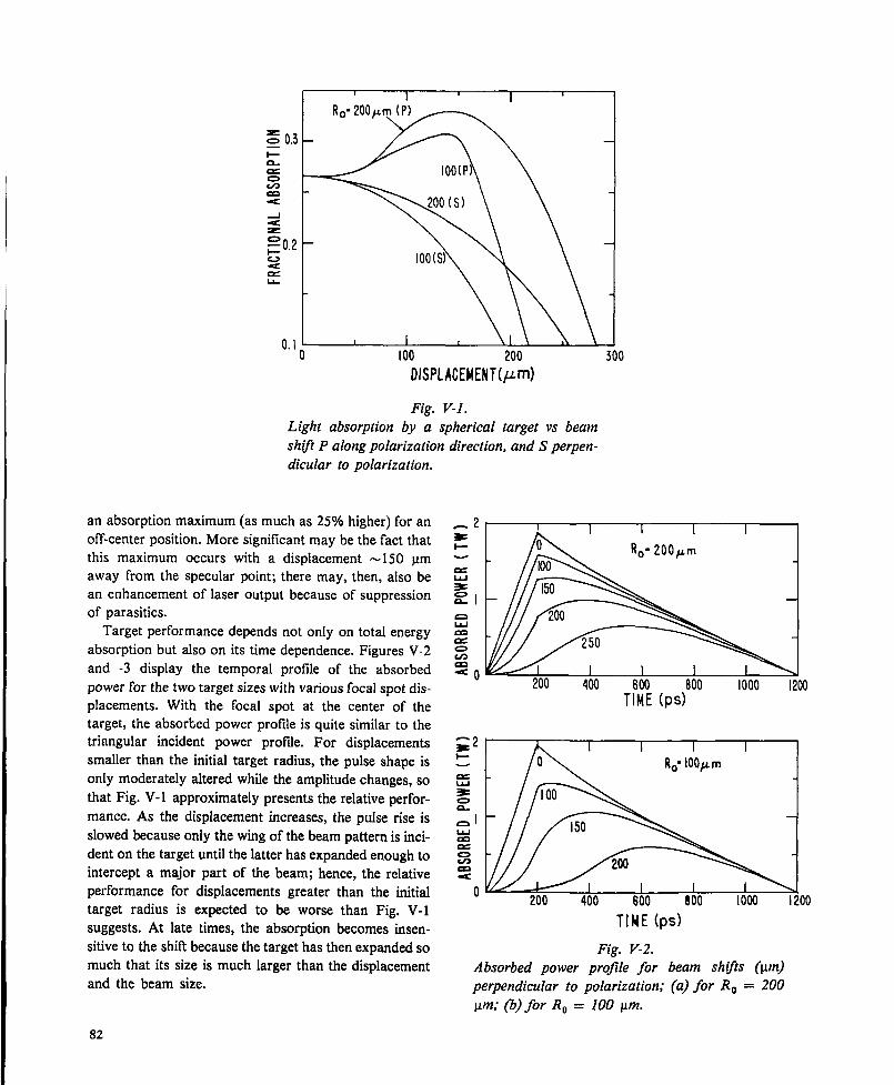
, I , I ,
z 0.3—i=a
U9
uJu
~o,2 –v 100(s)a
o.I t I t
o I00 200
DISPLACEMENT(/@
Fig. V-1.
Light absorption by a spherical target vs beam
shl~t P along polarization direction, and S perpen-
dicular to polarization.
an absorption maximum (as much as 25?40higher) for an
off-center position. More significant may be the fact that
this maximum occurs with a displacement -150 ym
away from the specular point; there may, then, also be
an enhancement of laser output because of suppression
of parasitic.
Target performance depends not only on total energy
absorption but also on its time dependence. Figures V-2
and -3 display the temporal profile of the absorbed
power for the two target sizes with various focal spot dis-
placements. With the focal spot at the center of the
target, the absorbed power profile is quite similar to the
triangular incident power profde. For displacements
smaller than the initial target radius, the pulse shape is
only moderately altered while the amplitude changes, so
that Fig. V-1 approximately presents the relative perfor-
mance. As the displacement increases, the pulse rise is
slowed because only the wing of the beam pattern is inci-
dent on the target until the latter has expanded enough to
intercept a major part of the beam; hence, the relative
performance for displacements greater than the initial
target radius is expected to be worse than Fig. V-1
suggests. At late times, the absorption becomes insen-
sitive to the shitl because the target has then expanded so
much that its size is much larger than the displacement
and the beam size.
200 400 600 800 1000 I200
TIME(f)S)
Fig. V-2.
Absorbed power profile for beam sh~ts (Km)
perpendicular to polarization; (a) for RO = 200
pm; (b) for RO = 100 pm.
82

n
mla
a
u
o
I I I I I I I
200 400 61XI 800 1000 1200
TIME (PS)
-1 I
imum attainable intensities in Helios, the measured hot
temperature T~ (for TC = 0.625 keV) was 35 keV,
whereas the formula3
TH = 30(IX2)’/3Tc1/3 ,
yields 30 keV; here 11.2is in units of 10*7 W . ym2/cm2,
and T~ and TC are in keV. At the lowest intensity of 1.2
x 1015 W . ~m2/cm2, T~ was 9.3 keV, in agreement with
the above formula. The new data points are shown in
Fig. V-4. This resu}t increases our confidence in using the
formula to predict the hot-electron temperatures.
Other noteworthy features of the highest intensity run
illustrate that the absorption process is extremely non-
E21W’””m1linear. First, the hot-electron temperature is less than the
oscillating energy of41 keV of an electron in the vacuum
electromagnetic field; it would be interesting to see
whether this behavior continues at higher intensities. Se-n~1
0 200 400 600 aoo 1000 1200
TIME(Ps)
Fig. V-3.
Absorbed power profile for beam sh@s (~) along
polarization (a) for RO = 200 pm; (b) for r. = 100
pm.
Extension of Suprathermal Electron Scaling Law (D. W.
Forslund)
Of great importance in the performance of laser-driven
targets is the spectrum of the suprathermal electrons
generated in the absorption process, We previously
reported3 a scaling law that tits the suprathermal electron
spectrum produced in two-dimensional WAVE simula-
tions and agrees rather well with the experimental data.
We verified that this scaling law is valid over an intensity
range an order of magnitude wider than reported
previously, now ranging from 1O1s to 2 X 10¹⁷ W .
ym2/cm2. This result was obtained on the CRAY - 1 com-
puter, which accepts grid sizes and performs at speeds
unattainable on the CDC 7600. At the highest intensity
run, 112 = 1.6 X 10¹⁷ W . Lm2/cm2, still below the max-
cond, the hot-electron density is three times higher than
the critical density, indicating that the hot-electron pres-
sure gradient at that density is insufficient to overcome
the balance between the cold-electron pressure gradient
and the laser pressure gradient. This situation exists even
though the hot pressure exceeds the cold pressure by
more than a factor of 3. The absorption remains above
25?ko over the entire intensity range.
Coherent Acceleration Of Hot Electrons (P. Bezzerides,
D. DuBois, D. Forslund)
In an effort to understand the physical mechanisms
responsible for the high-energy tails observed in simula-
tions of resonance absorption, we developed a simple
model of the acceleration process. The ultimate goal of
this work is to identify the controlling factors in the
development of the hot-electron spectrum and thereby to
determine the extent to which the spectrum can be
modified experimentally.
The model was studied numerically and analytically.
Basically, it assumes that the heating is due to coherent
acceleration when an electron passes through a large-
amplitude, localized, traveling wave with spatially vary-
ing phase velocity. Our numerical work, particularly the
phase-space plots, illustrates that the particle in the field
oscillates at large amplitudes about its guiding center,
and that this coherent oscillatory motion is interrupted
by resonant acceleration in the neighborhood of the
83

A ‘s .0.33
A 1.06-~m X-RN OATAO 10.6-pm X-RAYOATAIJ 10.6-pm ION OATA
m AO WAVE SIMULATION 1
,Ij’~10‘3 10” 10’; 10’6 10’1 Io”
1A (W.fim2/cm2 )
Fig. V-4.Hot-electron temperature vs laser intensity. The solid data points are WAVE simulation points and
the rest are experimental data. The new points are at 1.2 x 101’ and 1.6 x 10~7. The dashed curves
are the empirical scaling laws for three dl~erent background electron temperatures, TC= 0.625,2.5,
and 10.0 keV. The solid squares correspond to TC= 625 eV, the solid circles to TC= 2.5 keV, and the
solid triangles to TC = 10 keV.
resonance where the velocity is equal to the phase
velocity, leading to the final velocity of the particle. The
final time-averaged distribution function in V2is obtained
from the VI – V2transform plots, where VI is the velocity
at which the electron was injected into the field at early
time to exit the field with value V2at a given final time.
Most attempts to understand the heating analytically
have invoked the transit-time heating effect, which is the
only way to explain how particles that are already fast
can acquire still higher energies. We derived a general
formula relating vi to V2 by using a generalization of
guiding-center theory, which allows for large-amplitude
adiabatic motion, resonant interaction, and transit-timeeffects. We found that
v, = v~ expIf
I
* ah x(7) UH(X(X), Z) ,-(v~,t)T
(v-1)
relating the velocities of the velocity transform plot for a
given time t at which V2 is attained, where ~ is the injec-
tion time. In Eq. (V-1), uH[x(~),z] is the oscillatory
velocity of the particle at its position x(~) at time ~. Equa-
tion (V- 1) reduces to the well-known limits of guiding-
center motion, resonant heating, or transit-time heating,
but more important, it shows how the acceleration scales
with the inhomogeneity of the field. Evaluating the in-
tegral in Eq. (V-1) is, in general, as ditlicult as obtaining
the detailed trajectories. For the envelope of the VI — V2
transform corresponding to maximum acceleration for a
given Vz, we fmd
v, = V2 exp{ - (V2 -vi)/vph(xr)} ‘ (v-2)
with vPh(xr) denoting the phase veiocity at the resonantpoint given by vPh(x,) = Vz – Av, where Av =
4/7rJvo,(xrJvph(xJ. The most important limit occurs
when, in the frame moving with the phase velocity, the
acceleration due to the field is greater than that due to the
spatial phase inhomogeneity. Note that Av is equivalent
to the scaling result for T~ R eEt, where t-l is to be un-
derstood as k, the spatial phase. The predictions of Eq.
(V-2) compare favorably with the numerically deter-
mined v ~ — Vz envelope for the velocity transform plot;
we believe, therefore, that the coherent-acceleration
model is well understood. Progress is being made in un-
covering the role of coherent acceleration in our
simulations.
84

Hot-Electron Transport (R. Mason)
Elsewhere we described a double-diffusion scheme4 for
hot-electron two-dimensional transport in which the
suprathermal electrons were treated as a fluid. This treat-
ment, however, limited the precision of preheat predic-
tions. The need for accurate preheat calculations has
renewed our interest in Monte Carlo modeling.
The one-dimensional Monte Carlo transport code of
earlier reports (see LA-6245-PR) has been improved
significantly. As before, the hot electrons are treated as
area-weighted PIC particles, whereas the cold electrons
are treated as a fluid. The hot electrons are scattered, in
accordance with Jackson’s Gaussian distributions for
both angular deflections in Coulomb interactions and
decelerations from Coulomb drag. Their energy loss is
deposited in the cold electrons, which are also ac-
celerated in the local area-weighted electric field.
As an important new feature, we have calculated E
from Poisson’s equation in the “current” form, i.e.,
(v-3)
in which j~ is the suprathermal number flux, and ncuc is
the flux of cold electrons. We accumulate j, as a particle
property at the end of each cycle; nCuCis obtained from
the momentum equation for the cold electrons
[–
~p(r)
1~ +7+:)+ n eE(ml) It -v fitn u
-;-ax c
(v-4)
In general, with strong collisions (when vAt >>1), Eq. (V-
4) reduces to Ohm’s law, so that, in steady state,
~=oat ‘
with ~ PC/8x small, Eq. (V-3) yields
neF(ul+l)~g?+l)
= -ncuc = mb ‘
determining E(m+l).
Alternatively, for extremely high collision frequencies
so that the cold-electron velocities “are nearly zero, or if
there are very few cold electrons present ( v--+ m, so thatUc + 0, a for nC -+ O), Eq. (V4) becomes
aE (m+l )
= = 4=E~\s ‘
which could lead to enormous fields on a typical fluid
dynamic calculation mesh in which the cells are many
Debye lengths wide. To avoid such large E-fields, we
locally decrease the electron charge c so as to stretch the
local Debye length up to the calculational mesh dimen-
sions. This ensures that the E-field is of the order
a(%Ts)E= -(eGs)-l
ax
which we would derive near steady state from a moment
treatment of the suprathermal electrons.
This new Debye stretching technique is extremely im-
portant because, for the first time, we can track Monte
Carlo or multigroup electron transport in the low-density
corona around a pellet, where the density of suprather-
mal electrons exceeds the density of cold electrons. In
practice, the E-fields calculated by this technique es-
tablish quasi-neutrality over one or two calculational
cells. The stretched Debye length is somewhat akin to the
stretched mean free path employed with von-Neuman ar-
tificial viscosity.Figure V-5 shows typical ouput from a run with the
Monte Carlo code. A fixed gold profile has been il-
luminated with 1016 W/cm* of 1.06-~m light with 20V0
absorption for 2 ps. Frame 1 shows the density profiles
for hot and cold electrons and the critical density ZnP
Suprathermal electrons are created at the critical density
(Znl = 102’ cm–3) and are emitted toward the laser
beyond the corona. Frame (d) shows the phase space for
suprathermal electrons. They have been reflected by the
self-consistent E-field and flow with u < 0 out the left
side of the problem area. Electrons with u >0 in x < xCrit
(X,,,l z 31 -~m point) have been either scattered by the
ions or retarded by the E from Ohm’s law. Frame (b)
shows the reflecting E > 0 field in x > x,,~t and theretarding ohmic E-field in x < Xuit. Frame (c) shows the
hot and cold temperatures set up in the plasma at 2 ps.
The hot electrons are at roughly 20 keV. They are
generated in accordance with TH = 31.6 (IA2)*’3T~’3, and
the increasing background temperature of cold electrons
can, therefore, affect TH. To model this dependence with
a fixed number of simulation particles emitted during
85
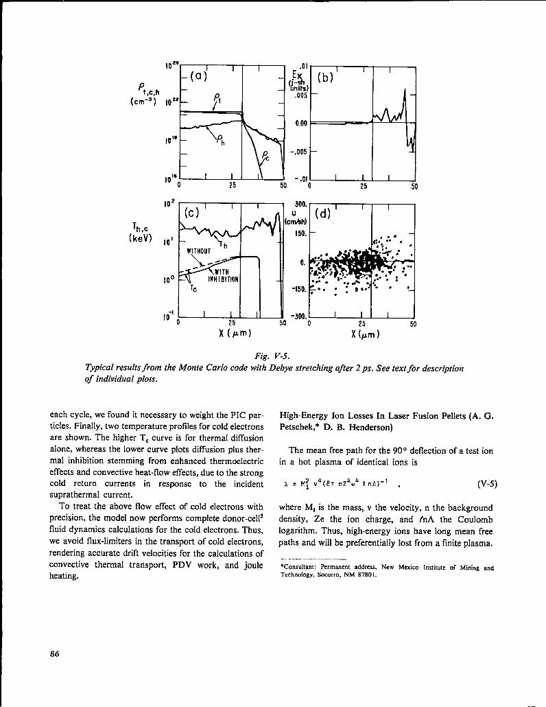
Pt,c,h
(cm-’)
I .01
’02s -(a)’ ~
1 ‘: F
v~~; (b) 11022–
..-
10” Ph~ NA-1
I HMA I
-J ‘“””~
Typical results from
of individual plots.
I I IdI l\- 11 -nnl
’02(c) ‘ I I
Th,c
(keV) ,01 * 4WITHOUT
~
Tc
10-’0 I I I25
X(pm)
3000
Chtd ‘d) ‘
I I
150.– ..4
● * .-150.~“. “ : ***: ““”–
●
-300.. 1 I 10 50
X i~m )
Fig. V-5.
the Monte Carlo code with Debye stretching after 2 ps. See text for description
each cycle, we found it necessary to weight the PIC par-
ticles. Finally, two temperature profiles for cold electrons
are shown. The higher TC curve is for thermal diffusion
alone, whereas the lower curve plots diffusion plus ther-
mal inhibition stemming from enhanced thermoelectric
effects and convective heat-flow effects, due to the strongcold return currents in response to the incident
suprathermal current.
To treat the above flow effect of cold electrons with
precision, the model now performs complete donor-cells
fluid dynamics calculations for the cold electrons. Thus,
we avoid flux-limiters in the transport of cold electrons,
rendering accurate drift velocities for the calculations of
convective thermal transport, PDV work, and joule
heating.
High-Energy Ion Losses In Laser Fusion Pellets (A. G.
Petschek,* D. B. Henderson)
The mean free path for the 90° deflection of a test ion
in a hot plasma of identical ions is
-1~2 “4(fIT n?”eu In!!) ,A=i (v-5)
where Ml is the mass, v the velocity, n the background
density, Ze the ion charge, and t’nA the Coulomb
logarithm. Thus, high-energy ions have long mean free
paths and will be preferentially lost from a finite plasma.
———_ —____*Consultant: Permanent address, New Mexico Institute of Mining andTechnology, Socorro, NM S7S01.
86
--
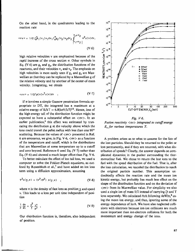
On the other hand, in the quadrature leading to the
reaction rate
V1+V2
<OV> = l/2 fo~l(vl)vl dv1J;’2(v2)v2dv2~ V29(V).5V,
IV1-V2I
(V-6)
high relative velocitiesv areemphasized because of the
rapid increase of the cross section a. Other symbols in
13q. (V-6) are gl and g,, the distribution functions of the
reactants, andtheir velocitiesvl andv2. The emphasis on
high velocities is most easily seen ifgl andgz are Max-
wellian so that they can be replaced by a Maxwellian g of
the relative velocity and by another of the center-of-mass
velocity. Integrating, we obtain
<Uv> = l/2f~(v)vSo(v)dv . (v-7)
If a involves a simple Gamow penetration formula ap-propriate to DT, the integrand has a maximum at a
relative energy of E/kT = 6.8(keV/kT)l’3. Hence, loss of
the high-energy tail of the distribution function might be
expected to have a substantial effect on <w>. In an
earlier publication,b this effect was estimated by trun-
cating the distribution g at the velocity above which the
ions could transit the pellet radius with less than one 900
scattering. Because the values of <OV> presented in Ref.
6 are erroneous, we give, in Fig. V-6, <w> as a function
of the temperature and cutoff, which is for distributions
that are Maxwellian at some temperature up to a cutoff
and zero beyond. Reference 6 used Eq. (V-7) rather than
Eq. (V-6) and showed a much larger effect than Fig. V-6.
To better calculate the effect of ion tail loss, we used a
computer to solve the Fokker-P1anck equations, as out-
lined by Rosenbluth et al.,’ and have added an ion loss
term using a diffusion approximation, assuming
(V-8)V2n(x, v) = (m2/R2) P(>, v) ,
where n is the density of fast ions as position~ and speed
v. This leads to a loss per unit time independent of posi-
tion
(v-9)
Our distribution function is, therefore, also independent
of position.
I0’5
10-’6
1o””
10-’8
7: I0-”m.
E .~~s 10~b -2,v 10*-~
: 10-22vau -23m 10
10-24
10-25
lo-q
10-27
I r
iI
, ! , I 1 1 I2 5 10 20 50 100 200 500
CUT-OFFENERGY,EC(keV)
Fig. V-6.
Fusion reactivity <w> integrated to cutoff energy
ECfor various temperatures T.
A problem arises as to what to assume for the fate of
the lost particles. Should they be returned to the pellet or
lost permanently, and if they are returned, with what dis-
tribution of speeds? Clearly, the answer depends on com-
plicated dynamics in the pusher surrounding the ther-
monuclear fuel. We chose to return the lost ions to the
fuel with the speed distribution of the fuel. That is, after
the loss calculation, we resealed the distribution to reach
the original particle number. This assumption un-
doubtedly affects the reaction rate and the mean ion
kinetic energy, but probably has much less effect on the
shape of the distribution function and on the deviation of
<OV> from its Maxwellian value. For simplicity we alsoused a single ion of mass 5/2 instead of carrying D and T
ions separately. We calculated tnA following deWitt,s us-
ing the mean ion energy, and thus, ignoring some of the
energy dependence of LnA. We have also neglected colli-
sions with electrons because ion-ion collisions are much
more important than ion-electron collisions for both the
momentum and energy change of the ions.
87

10.20
~
i=-
_~ 10-2’ :in
‘E1-acc
~ a.
G+-
01-
Z
~ A1-
>
vaw -22m 10 –IOJE
J
lo-z’ - I I I I 0.10 05 1,0 I.5 2.0 2.5x10’2
OENSITY-TIMEPRODUCT,nt(s“cm-3)
Fig. V-7.
Evolution of fusion reactivity <av~, temperature
T, and the ratio <GV> @)/<ov>, for an initial
A4axwellian distribution at T = 1 keV. Evolution
includes ion losses for PR = 10–4 g cm–z.
Figure V-7 presents the reaction history of a pellet
with a density of 180 g/cm3, a density-radius product pR
of 10–4 g/cm2, and a 1-keV Maxwellian initial ion dis-
tribution. The <m> average drops very rapidly, due,
largely, to a decrease in the average ion kinetic energy.
The ratio <cv>,~/<cw>, where the numerator is
calculated with a Maxwellian distribution at the mean
ion kinetic energy and the denominator is calculated with
the distribution from the Fokker-Planck code, reaches a
maximum of 3.9 at a density-time product nt x 10]2
s.cm-3 when the mean ion kinetic energy has dropped by
a factor of 2 and <m’> has dropped by a factor of -600.
Thus, the dominant effect is energy loss, but the tail loss
is not altogether negligible. Earlier in the history it is
IONENERGY (kev)
‘0-4‘~
10-s
=
1= -60 10
aL
—a1-
= 10-*
——. ORIGINf} yA[jE}LIAN.
_\—-— MAXWELLIAN AT PRESENT
ENERGY(T.O.759keV)
\\ — CALCULATE DISTRIBUTION\ FUNCTION
\
‘yE’”437 ‘*V
\\ \
\
\\
\ \1!
L4x2do 5 15 20
ION ENERG;O(NANOERGS)
Fig. V-8.
Distribution function for case of Fig. V-7 at time nt
= 2.01 x 10¹¹ s cm-3. A Iso shown are the original
l-keV Maxwellian and the Maxwellian at the pre-
sent energy. The latter yields a <m’> equal to the
evolving distribution function IYtruncated at ET =
4.37 keV.
relatively more important. For example, at nt = 2.01 X
1011 s.cm-3 when the mean ion kinetic energy is 0.76 of
the starting value, <w> is down by a factor of 14.8, of
which a factor of -6 is due to kinetic energy loss and 2.4
is due to tail depletion. Figure V-8 shows the distribution
function for this case, together with a Maxwellian dis-
tribution of the same mean energy. To reduce <CV> by a
factor of 2.4 at this temperature would require a cutoff at
4.37 keV, which is also shown.
To summarize, we have shown that losses from the tail
of the distribution function in small laser targets (those
with an area] mass = pR 10-2 #cm*) significantly affect
the reaction rate, partly because of the decrease in ion
kinetic energy and partly because of the deviation from a
Maxwellian distribution that results from preferential
loss of fast ions.
88

TARGET DESIGN
Exploding-Pusher Target Designs for Helios (W. P.
Gula)
From the time Helios became operational, we have
needed the capability to predict the performance of
various targets. Accordingly, we performed numerous
calculations. The two main purposes of the study are to
aid in the design and interpretation of experiments on
Helios and to calibrate our codes with the experimental
results.
Single-shell DT-filled GMBs were chosen for this
study because they are relatively simple and have only a
few variable parameters, the targets are easy to diagnose
experimentally, and we understand the physics of these
exploding-pusher targets. In our one-dimensional
calculations the glass shells were perfect spheres with an
initial density of 2.4 g/cm3, filled with an equimolar mix-
ture of deuterium and tritium.gMany parameters of the laser pulse and of the targets
were varied. The results show that the GMBs should
have a shell thickness of -1 Lm, a radius of 75 to 300
#m, depending on the laser power, and a fill pressure of
10 atm or less. The neutron yield as a function of laser
peak power for a given target and pulse width is shown
in Fig. V-9. The steepness of these curves emphasizes the
importance of the dependence on peak power of the
exploding-pusher targets in this regime. The one excep-
tion is the curve for targets of 100-~m radius; its slope is
much less steep, consistent with data from earlier work
with pulses of lower power. The steepness is less because
the implosion time of a 100-~m target is so short that
only limited amounts of energy can be transferred to the
fuel before disassembly begins, even for very high peak
powers.
Preliminary target shots on Helios were made at low
powers (2 to 5 TW). Neutron yields ranged from 2 to 3
X 108n. in agreement with calculationsfor the specific
I 400um I
‘-i7// / -1
/
10°
PEAK POWER (TW)
Fig. V-9.
Neutron yield as a function of laser peak power.
tions, and the rewriting of the laser ray-trace package to
allow for rays that do not pass through the coordinate Z-
axis. The effort to adapt some codes to the CRAY-I
computer was redirected slightly to aim at FTN compila-
tion. This effort is progressing well and will be finished in
targets used. late summer 1979.
CODE DEVELOPMENT Off-Axis Ray-Trace Routine (G. A. Rinker)
Introduction (K. A. Taggart) The laser ray-tracing routine in previous versions of
our codes required that each ray pass through the Z-axis
The two major efforts in code development during the at some point for the sake of simplicity. If we view a
past 6 months were the incorporation of nonlocal cylindrical coordinate system in three dimensions and
thermodynamic-equilibrium physics for opacity calcula- imagine representing a laser beam by a bundle of
89

straight-line rays, we can see that a general description
may be obtained only if some rays are allowed to miss
the Z-axis. The on-axis description can be complete only
for a beam focused to an infinitesimal spot size on the
axis.
Although a complete three-dimensional ray trace (in
Cartesian coordinates, for example) would increase ex-
ecution time significantly, a suggestion made earlier may
be used to exploit the cylindrical symmetry of the targetand remove analytically the angular degree of freedom.l”
This treatment does not introduce additional physical ap-
proximation because the noncylindrically symmetric ray
path is effectively averaged over all angles when coupled
to the cylindrical target.
The geometrical ray-trace equation is
(v-lo)
where ~ describes the position of the unit-mass particle
whose path describes the ray trajectory, and
n2(7) = 1 - De(Y) (V-n)
is the index of refraction, where pe~) is the electron den-
sity measured in units of the critical density. The speed
of the particle has been set to 1. For a cylindrically sym-
metric target, pe(~) does not depend on 9, so that the
above equation becomes
laF=-–— 2 ar [~e(r’z) + L~/r2]
and
1 3 [pe(r, z) + L$/r2]?’-~~ > (V-12)
(V-13)
is the conserved angular momentum. Thus, the complete
three-dimensional solution may be obtained from the
former restricted solution merely by the addition of a
new term to the density, yielding an effective density
pJ,z) + L~/r2. In vacuum, the equations may be solvedanalytically, with the resulting ray path
90
r2 COS2 y = L; cot2 y + (z sin y - rB)2 , (V-14)
where y and r~ are parameters that describe the ray
asymptotes. The distance of closest approach of the ray
to the Z-axis is
‘mi n = -Lz/sin y . (V-15)
The ray-trace equations are reduced to those used
previously in our design codes when L= = O.
This new capability was implemented in the codes. A
given ray is traced in vacuum according to the hyper-
bolic path given in E@. (V-14). When a material boun-
dary is intersected, the ray is traced through with linear
approximations to the term L~/r2 in each cell as is nor-
mally done for the true density. This overall procedure
suffers from a numerical problem due to the singularity y
in L~/r2 as r approaches zero, with the result that rays
are not traced accurately in the cells adjacent to the z-
axis. However, this inaccuracy has little physical
significance, because there is very little volume in such
cells. Further problems arose in implementing this
capability because the previous critical-surface turning-
point detector is not valid in the new context. This situa-
tion was corrected, and an approximation to the ob-
served angular-dependent resonance absorption was ad-
ded at the same time.
The problem of physical interest concerns a laser
beam focused to some finite spot. To approximate this
situation by using geometrical ray-trace optics, it is
necessary to produce a bundle of rays distributed ac-
cording to some intensity pattern in the focal plane. This
pattern is obtained in the following way. A nominal focal
point is described as before in the (r,z) plane; then ran-
dom fluctuations in L, and the angle y are imposed to
yield an intensity pattern corresponding in the limit of an
infinite number of rays to a Gaussian of specified
FWHM. More general intensity patterns may be ob-
tained with superpositions of such Gaussians, subject
always to the cylindrical averaging process mentioned
before, which transforms off-axis focal points into rings.
These fluctuations are rerandomized at each cycle. Ad-
ditional random fluctuations in LZ and y may be imposed
at reflections within the target.
An example of the effects of these modifications is
shown in Figs. V-10 through V-13. Figure V-10 shows a
ball with a laser focused to a point on each side of the

7 I I
““:’LL2!J-103 0 u)” 200
Z(pm)
Fig. V-10.On-axis laser illumination of spherical target.
p 102–z3
&aa1-= 10’–~>kGpZI
10’ ! I I-1oo -50 0 50 100
Z (pm)
Fig. V-II.Laser intensity on sphere of Fig. V-IO as a func-
tion of z.
Z (pm)
Fig. V-12.0#-axis laser illumination of sphere in Fig. V-IO.
Z (pm)
Fig. V-13.Laser intensity on sphere of Fig. V-12 as a func-
tion of z.
sphere; the corresponding intensity as a function of z is
shown in Fig. V- 11. Figures V-12 and -13 show the same
configuration except that finite focal spots of 100 ~m
have been imposed. A significant change in overall il-
lumination is evident from the trend of the graph in Fig.
V-13. Note that the fluctuations are statistical and tend
to disappear over time because of the rerandomizing car-
ried out during each cycle. The increase in symmetry is
the most obvious manifestation that our new laser ray-
tracing capability reflects the physics of pellet irradiation
more accurately.
REFERENCES
1.
2.
3.
4.
H. Brysk and A. J. Scannapieco, Bull. Am. Phys.
SOC. 23, 750 (1978).
M. A. Stroscio, D. B. Henderson, and A. G.
Petschek, Nucl. Fusion 18, 142.5 (1978).
D. W. Forslund, J. M. Kindel, and K. Lee, Phys.
Rev. Lett. 39, 284.
R. J. Mason, “Double Diffusion in Hot Electron
Transport in Self-consistent E and P Fields,” Phys.
Rev. Lett. 42 (1979).
91

5. R. A. Gentry, R. B. Martin, and B. J. Daly, “AnEulerian Differencing Method for Unsteady
Compressible Flow Problems,” J. Comp. Phys. 1,
87 (1966).
6. D. B. Henderson, Phys. Rev. Lett. 33, 1, 142 (1974).
7. M. N. Rosenbluth, W. M. McDonald, and D. L.
Judd, Phys. Rev. 107, 1 (1957); and W. M.
McDonald, M. N. Rosenbluth, and W. Chuck, Phys.
Rev. 107, 350 (1957).
8. H. deWitt, Lectures in Theoretical Physics Vol. IX,
Part C (Gordon and Breach, 1967) p. 621.
9. C. W. Crantill, “One-Dimensional Computer
Simulations of the Implosion of Single-Shell Targets
with the Los Alamos Two-Beam C02 Laser,” Los
Alamos Scientific Laboratory report LA-6827-MS
(1977), Fig. 11.5.
10. F. Tappert, University of Miami, Florida, and E.
Lindman, Los Alamos Scientific Laboratory, private
communication (1978).

VI. LASER FUSION TARGET FABRICATION
(R. J. Fries)
Our target fabrication effort, supported by extensive theoretical investigations, sup-
plies thermonuclear-fuel-containing pellets for laser-driven compression and heating ex-
periments. These targets, which range from simple, deuterated, flat plastic films to com-
plex, multilayered structures containing cryogenic solid DT fuel, are optimized for use
with high-power C02 lasers. After a target has been designed, we develop thetechnologies to produce the materials and properties desired. Then, we fill the target
with thermonuclear DT fuel, assemble the necessary parts, and develop methods to
measure and characterize all these properties. Finally, we insert the target in the target
chamber and position it at the exact laser focal spot.
INTRODUCTION (E. H. Farnum, R. J. Fries)
Our target fabrication effort has two objectives:
(1) We supply targets of current design to satisfy the
needs of the experimental program. Targets of various
designs are used: thermonuclear compression targets for
Main-Sequence experiments, partial and modified com-
pression targets for Target-Essentials experiments, a
wide variety of targets for Support-Physics experiments,
and several types of targets for Military Applications ex-
periments. All are irradiated in one of our laser systems.
(2) We develop new techniques as needed for the
fabrication of future thermonuclear compression targets
envisaged in the Inertial Fusion Program plan. Because
these target designs are not freed, we must continue to in-
vestigate all materials that have a high probabllit y of be-
ing used in the final designs. We also develop methods of
measuring and characterizing these materials and of
assembling them into required configurations.In addition to these goals, we provide micromachin-
ing, microassembly, and materials fabrication services to
other groups.
A recent design for the Polaris-A multishell laser fu-
sion target is shown in Fig. VI-1. Laser fusion targets
have evolved slowly to this stage. Initial targets, called
Sirius, comprised only one shell tilled with room-
temperature DT gas. This single shell acts as an ex-
ploding pusher in which the fuel is preheated as it is com-
pressed. Most of these shells are GMBs with only a few
atmospheres of DT gas fill. Although these designs can-
not lead to a high yield, they do produce some ther-
monuclear reactions and neutrons. The target is
improved by adding a 100-ym-thick layer of plastic,
which is vaporized by the laser pulse causing the glass
—.—
-“-”/—ABSORBER
.-. .—. .- . . ..—
/
OUTER-PUSHER———
——
“/---DT ICI OR FOAM
~./’ INNER PUSHER
K“ ~ DTICE
_~~ALLDlAMETER:2mm--- ... -. .—. . . . ,-*
Fig. VI-1.
Polaris-A, a multilayer multishell target designed
for Antares and Helios.
shellto implode hydrodynamically. By coating the GMB
with molybdenum or other high-Z metal before plastic
deposition we reduce preheat, and thus, make the desired
adiabatic hydrodynamic compression possible. Such a
design will be used to attain our 20XLD milestone.
In our Polaris-A target, this high-Z metal coating is
added as a heat shield for the fuel, the ablator layer is
changed to low-density plastic foam to provide a
hydrodynamic cushion, and a second pusher layer is ad-
ded outside the foam.
Initial targets will irradiate the outer pusher shell
directly, but in subsequent experiments other layers will
be added to provide further thermal insulation, to
93

enhance laser absorption, andto improve hydrodynamic
coupling of the laser energy to the target.
In all these targets, from the simple Sirius to Polaris
(Fig. VI- 1), the fuel will be frozen as a solid layer of DT
ice onto the inside surface of the innermost pusher shell.
Calculations show that this cryogenic modification willimprove the yield substantially. We are developing
techniques to freeze such layers in place within the
Helios target chamber.
These and other targets of recent design call for the
development of high-Z metal shells with diameter and
wall-thickness uniformity deviations of not more than
1% and a surface smoothness tolerance of <1000 ~.
They also require low-density, small-cell-size plastic
foams, thick layers of plastic loaded with metals of low
or high Z, metal foams, and smooth metal layers of
moderate or low Z. In addition, we are developing
methods to prepare alternative fuels that are solid at
room temperature and contain fuel atoms at high density
(e.g., polyethylene, lithium hydrides, or ammonia borane,
in which the hydrogen is replaced by an equimolar mix-
ture of deuterium and tritium). Even though the nonfuel
atoms in these compounds dilute the nuclear fuel and
reduce target performance, the fact that these materials
are solid at room temperature may be an advantage, es-
pecially in designs that require fuel-containing layers in
the outer parts of the target.
Because any target must be characterized completely
to understand its performance, we have devoted much of
our effort to measuring and documenting all targets we
deliver and to developing new, automated high-resolution
met hods of characterizing target parts. We are develop-
ing a surface acoustic-wave resonator-driver to sort
batches of target shells for diameter and wall uniformity
using the efficiency (Q-value) and frequency at which the
shells bounce as an indicator of quality. We are also
automating our x-ray microradiographic method for
observing defects and nonuniformities in opaque shells.
TARGET FABRICATION (R. J. Fries, E. H. Farnum)
In addition, we try to maintain a large and very flexible
inventory of materials and techniques so that we can res-
pond rapidly to changes in target design or specifica-
tions. As part of target assembly, we also mount and
align the targets on the appropriate target-changing
mechanism to eliminate the need for any further position
adjustment in the target chamber. If desired, we
photograph and analyze any remnants to supplement
target diagnostics.
The process of target fabrication typically includes the
following steps. A type of GMB is chosen that is most
suitable for the desired diameter, wall-thickness, and gas-
permeation characteristics. These GMBs are available
from the 3M Company, KMS Fusion, Inc., or the
Lawrence Livermore Laboratory. The GMBs are
precision-screened to the desired size on an air-jet sieve,
separated according to density by flotation in SF6 gacrushed by external pressurization (only for cases where
the desired wall thickness is greater than 1.5 pm), and
cleaned by flotation in ethanol. The refined batch is op-
tically preselected with an interference microscope and
then filled with DT or DT:Ne gas mixtures by permea-
tion through the wall at elevated temperature and pres-
sure. The filled GMBs are cleaned in ethanol and ex-
amined carefully with an interference microscope.
Targets passing optical inspection are examined and
measured in three planes. Coatings of metal and/or
plastic are then applied. These coatings are examined in
three views by x-ray microradiography to determine
coating smoothness and uniformity, often afler each suc-
cessive layer has been applied. In the meantime, other
parts are being fabricated. For example, for the two-shell
vacuum insulation target (see Fig. VI-2), we form the
outer plastic shell by coating an appropriately sized cop-
per ball bearing with plastic (by our low-pressure plasma
polymerization method described below), cutting the
coating into two halves with a laser knife, and etching the
copper mandrel away in nitric acid to leave the plastic
hemispheres. When the central fuel container is opaque,
we use x-ray microradiography to determine shell unifor-
mity.
GeneralFabrication Activity (B. CranfN, V. Woods, M. Calcote,
Our primary assignment in target fabrication is the as- J. Feuerherd)
sembly, delivery, and postshot analysis of targets for our
three operating laser systems. We therefore devote We supplied more than 1000 targets for our threewhatever fraction of our effort is required to meet operating laser systems and made more than 100 partsdelivery requests from experimenters on these systems. for diagnostic devices. About 320 targets were fabricated
94

Fig. VI-2.A two-shell target consisting
single concentric plastic shell.of a GMB and a
for main-sequence experiments. Another 340 targets
were supplied for a wide variety of Target-Essentials and
Support-Physics experiments, including preliminary
shots on the Helios laser, and over 400 were made for
military applications experiments.
We completed the development of fabrication techni-
ques for the current Vega-B target. We also improved
our low-pressure plasma polymerization technique and
can now coat mounted GMBs with over 350 ~m of
parylene for the 20XLD milestone target. The surface
smoothness of this coating is acceptable (+ 1 ~m). We
solved the problem of perturbations near the mounting
stalk, which are introduced because both the GMB and
the stalk are coated simultaneously in the coating
process. We are replacing the coated stalk with a new,
uncoated one by micromachining with a single-point dia-
mond tool that has a concave tip. This technique
produces a smooth spherical surface at the cutoff. We
successfully fabricated several targets for an x-ray point-
source experiment which requires a tungsten needle
suspended behind an aperture in the configuration shown
in Fig. VI-3.
Gas Analysis of Laser Fusion Targets
General. To predict the performance of hydrogen-,
deuterium-, and DT-filled microballoons correctly, we
must be able to measure the gas fill with a high degree of
accuracy. Also important are the permeation rates of the
hydrogen isotopes through thin layers (shells) of a
variety of coating materials at various temperatures. This
information will be helpful in deciding under what condi-
tions a given target type can be filled in real time.
Permeation data at room temperature and below will
also be important in selecting the best storage
temperature for targets tilled with the desired quantity of
fuel gas.
Filling Large-Aspect-Ratio ShelIs for the 20XLD
Milestone Target (Betty S. Cranfill). The 20XLD
milestone target requires 300- ~m-diam, 1-yin-wall
GMBs tilled to 30 atm (3 MPa) of DT gas at room
temperature. Two problems were encountered in filling
these targets. (1) Commercially available batches of 300-
~m-diam GMBs are of very poor quality and of a glass
composition that permits high DT loss rates even when
stored at —80° C (193 K); and (2) the aspect ratio
(diameter/wall thickness) of these shells was so large that
they collapsed by elastic buckling during the fill (the
resulting shock wave and/or fragments break other near-
by shells) with the result that even with precrushing and
careful staging, only - IO?40of the GMBs loaded for DTfill survived. Both problems were solved during this
reporting period; we are now fiiling 300-~m-diam, 1-~m-
wall GMBs with 30 atm of DT and achieving 90°A
recovery.
In trying to solve the first problem, we obtained some
GMBs from KMS Fusion, Inc., that were not only of
very high quality with respect to wall uniformity and sur-
face finish, but also had very low permeability to DT at
room temperature due to ~ 12% CaO content in the
glass. We measured the outgassing rate of GMBs from
KMS Fusion, Inc., with and without CaO addition by
monitoring the x-ray emission of a number of shells over
a period of time; the results are shown in Fig. VI-4. The
high quality of these shells significantly reduces the time
needed for selection and improves the gas-filled yield by
reducing elastic buckling failure.
We solved the buckling problem by isolating the GMB
during fill and measuring buckling failure so that fill-
staging might be optimized. Isolation was provided by a
95

Fig. VI-3.An x-ray backlighting target. The tungsten needle pointedtoward the ho[e emits x-rays from its tip
when heated by the laser.
I00 ‘z-
12”/. coo
60
40
20 -
10 1 I 1 I I I 1
0 I 2 3 4 5 6 7 8 9
Fig. VI-4.
X-ray count rate data from KIUS Fusion, Inc.
GMB as a function of titne. The relative time forDT outgassing is sho wnfor (7MB with and without
CaO.
TIME (months)
96
—- .

wire with holes drilled into it, each of which acts as an in-
dividual container for a GMB during the DT filling
process. Thus, each GMB is shielded from its neighbor.
The wire containing the GMBs is then placed into a
close-fitting glass capillary which retains the GMBs in
their holes. Another advantage (other than 9070 recovery
from 30-atm DT fill) of this technique is that the identity
of the GMB is maintained during till, which permits the
recovery of precharacterized shells. Because the fdl gas
contributes to the wall thickness measuredly optical in-
terferometry and must be subtracted, wall thickness can
be measured more accurately on an empty GMB. In ad-
dition, wall thickness carefully measured before and after
filling can be compared to obtain a nondestructive, quan-
titative gas assay. Although this method is much more
tedious than x-ray counting, we used it as an aid in
calibrating the x-ray counting system for glass shells.
Variations among different shells indicated an x-ray
calibration error of -+7°YiX
Data for interferometrically measured gas content in
GMBs at several fill pressures are plotted with the ex-
pected fill density in Fig. VI-5. All these GMBs, which
were held at fill conditions for 24 h, showed a lower-
than-expected gas content. In contrast, a 10-day fdl to an
expected 28 amagat at the same temperature showed
outside Diameter (#m)
Fig. VI-5.
Inter ferometric measurements of the amount of DT
gas in GMB. The dl~erence in optical path length
before and after DT fill in a GA4B is plotted
against the outside diameter of the shell for several
j711pressures and is compared to the curve expected
for the jlll conditions used.
29.8 + 1.4 amagat in 10 shells. These data, which would
indicate a permeation time longer than 24 h conflict with
those of still another experiment in which similar GMBs
were emptied of gas by heating in air for only 4 h.
Further experiments to resolve these contradictions are
in progress.
Buckling Failure in Large-Aspect-Ratio Shells (John
V. Milewski). The tensile strength of shells determines the
design limitations on the maximum achievable fuel
loading. A method of testing for tensile strength was dis-
cussed in the last report (LA-7587 -PR). However, the
current limitation in loading shells with fuel is not the
tensile stress from internal gas pressure but rather com-
pressive buckling failure during diffusion-fill. The low
buckling strength of larger diameter spheres with thinner
walls severely limits the external filling pressure that can
be applied to the shells during diffusion-filling. For exam-
ple, at present, we use 100-psi fill stages for 300-~m-
diam, 1-pm-wall GMBs; to achieve a fuel density of 30
amagat at 673 K, we must use 11 stages at 24 h each.
Because relatively few preselected GMBs are tilled in a
single run, optimizing the fill staging is obviously very
important.
We built an apparatus for measuring the crushing
strength of shells and determined the room-temperature
crush strength for GMBs in the size range currently be-
ing used for targets. These data agree very well with the
theoretical relationship for elastic buckling (Fig. VI-6)
given by
P =2yAr2exx r’=’
where p~~x is the externally applied pressure at whichbuckling occurs, Y is Young’s modulus, v is Poisson’s
ratio, Ar is wall thickness, and r is shell radius. Note that
the buckling-failure pressure is inversely proportional to
the square of the aspect ratio (diameter .wall thickness)
and that an increase in diameter from 100 to 300 ~m at
constant wall thickness should reduce the buckling-
failure pressure by a factor of 9. For example, 10O-ym-
diam shells with 1-yin-thick walls do not fail by compres-
sive buckling at room temperature until -5000 psi of ex-
ternal pressure is applied, whereas 300-~ m-diam, 1.O-
~m-thick targets fail when -550 psi of external pressure
is applied.
We do not expect this relationship to apply at elevated
temperatures because the glass becomes plastic rather
97
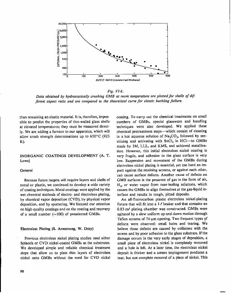
20,000\
1 1 { I 1 I~Io,ooo-
za 5,000 -~
K!
$ 2,000 -
$
g 1,000 -
dg 500 -
~●
200 - ●
I 00 1 ! I I I - ●
o 100 200 300 400 500 600
ASPECT RATlO [diomeler/wall thicimsss)
Fig. VI-6.
Data obtained by hydrostatically crushing GMB at room temperature are plotted for shells
ferent aspect ratio and are cotnpared to the theoretical curve for elastic buckling failure.
than remaining an elastic material. It is, therefore, impos-
sible to predict the properties of thin-walled glass shells
at elevated temperatures; they must be measured direct-
ly. We are adding a furnace to our apparatus, which will
allow crush strength determinations up to 650°C (923
K).
INORGANIC COATINGS DEVELOPMENT (A. T.
Lowe)
General
Because future targets will require layers and shells of
metal or plastic, we continued to develop a wide variety
of coating techniques. Metal coatings were applied by the
wet chemical methods of electro- and electroless plating,
by chemical vapor deposition (CVD), by physical vapor
deposition, and by sputtering. We focused our attention
on high-quality coatings and on the coating and recovery
of a small number (-100) of preselected GMBs.
Electroless Plating (S. Armstrong, W. Doty)
Previous electroless nickel plating studies used either
Solacels or CVD nickel-coated GMBs as the substrates.
We developed simple and reliable chemical treatment
steps that allow us to plate thin layers of electroless
nickel onto GMBs without the need for CVD nickel
of dt~-
coating. To carry out the chemical treatments on small
numbers of GMBs, special glassware and handling
techniques were also developed. We applied these
chemical pretreatment steps—which consist of cleaning
in a hot aqueous solution of NaZCOJ, followed by sen-
sitizing and activating with SnC12 in HC1—to GMBs
made by 3M, LLL, and KMS, and achieved metalliza-
tion. However, this initial electroless nickel coating is
very fragile, and adhesion to the glass surface is very
low. Suspension and movement of the GMBs during
electroless nickel plating is essential, yet too hard an im-
pact against the retaining screens, or against each other,
can cause surface defects. Another cause of defects on
GMB surfaces is the presence of gas in the form of air,
Hz, or water vapor from near-boiling solutions, which
causes the GMBs to align themselves at the gas-liquid in-
terface and results in rough, pitted deposits.
An all-fluorocarbon plastic electroless nickel-plating
f~ture that will fit into a 1-/ beaker and that contains an
0.83-mf plating chamber was constructed. GMBs were
agitated by a slow uniform up-and-down motion through
Teflon screens of 74-~m opening. Two frequent types of
defects were observed: small holes and tearing. We
believe these defects are caused by collisions with the
screen and by poor adhesion to the glass substrate. If the
damage occurs in the very early stages of deposition, a
small piece of electroless nickel is completely removed
and a hole is left. At a later time, the electroless nickel
deposit is thicker and a screen impingement produces a
tear, but not complete removal of a piece of nickel. This
98

flap of nickel will lie unevenly on the surface and subse-
quent deposition forms a rough modular part. We are in-
vestigating ways of improving the adhesion between the
GMB and the initial nickel coating.
Chemical Vapor Deposition (G. J. Vogt)
We completed construction of the fluidized-bed CVD
reactor designed to allow us to quantitatively analyze the
fluid bed. ~his reactor system, designed specifically to
study the WFC+HZ reaction, is also useful for other CVD
reactions. We are investigating the system controls and
diagnostics.
Experimental work on a Solacel fluidized bed was
started with the WF~+H2 CVD reaction to ascertain
operating conditions for the optimum coating qualities
and to relate these conditions to fluid-bed parameters.
We also completed the literature search for available
thermodynamic and molecular data for the WF6+HZ
reaction. The subsequent computation for the ther-
modynamic yield of CVD tungsten as a function of Hz
and WFC feed ratio was performed by using these col-
lected data. In general, for all pressures and
temperatures, a 99’%0tungsten metal yield can be ob-
tained at equilibrium for an input ratio of Hz to WFG
between 3.0 and 3.3. Note that the stoichiometric input
ratio of HZ:WFC is 3.0, as given in the reaction
Sputter-Coating, a Gas-Jet Levitator Development (A.
T. Lowe, C. Hosford)
We continued our development of sputter coatings on
GMB and other spherical mandrels. By using the gas-jet
levitator described in the previous progress report,l we
have successfully applied molybdenum and gold to
levitated GMBs. The cotilguration that allowed success-
ful GMB levitation is shown in Fig. VI-7.
The GMB is observed from outside the chamber
through a 10-cm-diam viewport with a Questar
telescope, and illumination of the sphere is maintained
throughout the run with a 4-mW He :Ne laser whose
beam passes through a second viewport and is directed
onto the GMB with mirrors inside the sputtering
chamber.
The gas flow (measured with a mass flowmeter) re-
quired to levitate a GMB is between 0.1 and 0.2 cm3/min
at sputtering pressures from 20 to 100 mtorr, At these
flow rates, additional argon must be added to the bell jar
to establish sputtering pressures of 40 mtorr.
Initial liftoff of the GMB from the collimated hole
structure (CHS) is diflicult because of static charging of
the GMB. Increasing the gas flow sufficiently to lift the
sphere would often blow the GMB away (typical GMB
weight, 2 ~g). However, an electromechanical driver (as
used for the shaker table) attached to the CHS vibrated
the structure sufficiently to gently dislodge the GMB and
wF6(g) + 3H2(g) : w(s) + 6HF(g).
Because CVD is generally a nonequilibrium process due
to a short residence time in the reaction zone, additional
Hz is necessary to ensure a high W(s) yield. Also, the
yield of tungsten metal by CVD appears to be specifical-
ly dependent on the kinetics of the process.
A similar thermodynamic analysis for W(CO)~ CVDu
is being considered as an alternative to WF6 CVD for
GMBs because, in the earliest stage of the WF~ process,
the GMBs are quite susceptible to HF attack, yielding
badly damaged bed material. We could alleviate this
problem by either fully coating the GMBs with the
W(CO)~ process or by flash-coating the glass with the Fig. VI-7.
W(CO)C process before further coating with the Schematic of rf sputtering unit with its gas-jet
WFC process. levitator.
99

to permit liftoff at low gas flows. To keep static charges
to a minimum, the GMB must be coated with a thin
(200- to SOO-A) metallic layer before levitation, stored in
metal containers, and treated with commercial
electrostatic-charge-eliminating devices.
The metallographic cross section of a gold coating 1.4
+ 0.2 Am thick is shown in Fig. VI-8. This coating wasdeposited at a rate of 4.2 nm/min onto a 200-~ m-diam
GMB with a 2.O-~m-thick wall.
To keep the sphere levitated, a delicate balance must
be maintained between the two counteracting forces of
gravity and levitation-gas pressure. Therefore, the
levitation-gas flow must be increased as the weight of the
GMB increases during coating. For the gold coating in
Fig. VI-8, we had to increase the flow from an initial rate
of 0.1 cm3/min by 0.02 cm3/min for every 100 nm of
gold film added. Preliminary coatings made with this
technique show much cleaner, smoother surfaces than
the vibrating-table scheme used previously.1
The disadvantage of this technique is the low deposi-
tion rate achievable at the high pressures necessary for
stable levitation. Finer gas-flow controls and improved
designs of directional jets, which should allow operation
at higher rf power and lower pressures, are being tested.
Microflow Valve (J. R. Miller, J. Feuerherd)
The need for precise gas flow with a controllable rate
of 0.001 to 1.0 std cm3/min for the gas-jet levitator
coupled with the lack of a suitable commercial device led
to our development of a microflow valve.
The simple device, shown in Fig. VI-9, relies on the
thermal expansion difference between a precisely lapped
tungsten plug and the surrounding brass body. As the
temperature of the assembly is raised by the resistance
heater coiled around the valve body, the brass expands
more than the tungsten and a gap forms around the plug,
allowing gas to flow through the device. Typical flow
rate vs temperature at three pressure differentials for one
Fig. VI-8.
Optical metallograph of the cross section of a I.4-
pm-thick gold coating sputtered onto a levitated
GMB. 2500X
100
P.
STAINLESS STEEL TUBING
+BRASS BOOY
k RESISTANCE HEATER
u
kTUNGSTEN PLUG
THERMOCOUPLE
STAINLESS STEEL TuBING
GiS FLOW
Fig. VI-9.
Schematic of temperature-controlled microjlo w
valve.
—

:F77~E,,l“
~
LA(4:003!3
: AP=4 X10⁴P0
~ 00020Ii
Ocfn AP=2X10⁴P0
o cn2
o20 40 60 80 100 I20 140
T[MP2RA1URE [Cl
Fig. VI-10.
Flow rate for helium gas as afunction of orl~ce
temperature for the microflow valve.
of these valves is shown in Fig. VI-10. The sensitivityy of
this valve can be changed by choosing plug and body
materials that have either greater or less difference in
their thermal expansion coefficients.
Sodium nitrite spheres -250 to 500 ~m in diameter
were produced by dropping the molten material at 563 K
through a 300-~m orifice. Although the drops solidified
in the 1.5-m drop length, some spheres contained bub-
bles. We have not yet metal-coated this product.
Polymethyl methacrylate (PMMA) spheres were CVD
nickel-coated at -355 K. Although the PMMA does dis-
solve through a thin (-2-~m) coating without adverse
swelling, most of the shells crumple without mandrel sup-
port. Observation with an optical microscope showed
that some shells with a wall thickness of 1.1 to 1.4 ~m
remained intact after removing the PMMA. Because
high-energy radiation is known to decompose PMMA,
promoting dissolution, this fact may allow easier removal
of the mandrel material through the nickel wall.
Therefore, we have irradiated some PMMA spheres with
a linac electron beam. Evidence of decomposition of the
material appears at doses of -50 Mrad, but quantitative
analysis of the change in volubility is not yet complete.
ORGANIC COATINGS DEVELOPMENT (R.
Liepins)
GeneralMandrel Development (S. Butler, M. Thomas)
Work toward making mandrels for metal microbal-
loons continued. This effort should produce
microsphere that can be coated with nickel by chemical
vapor deposition (CVD), and that can be removed
through the coating, leaving a shell strong enough for ad-
ditional coating. The resulting product is a free-standing
metal microballoon, with the inside diameter dependent
upon the mandrel size and the wall thickness determined
by the coating process. We further investigated condi-
tions for spherical droplet formation, using water in the
droplet generator described in Ref. 1. The size of the
drops was measured by viewing them in free fall with a
telescope, video-camera assembly, and stroboscopic
light, which have been calibrated for such measurements.
Droplet size measured for a 140-~m orifice agrees well
with that predicted from mass balance, liquid-jet
velocity, and excitation frequency. However, drops
formed with a 68-urn orifice are substantially larger than
predicted (by 1.5 to 2.5 times) and the measured size
does not correspond to any overtone or simple divisor of
the excitation frequency. We cannot offer an explanation
for the discrepancy yet.
Many of our multilayered laser fusion targets use an
outer shell of low-density, low-Z material as an ab-
sorber/ablator layer. This layer absorbs energy from the
incident laser, is heated and vaporized, and streams
away from the pusher shell causing the pusher shell to
implode via the rocket reaction forces. For target pellets
that do not depend on the strength of this ab-
sorber/ablator to contain the fuel-gas pressure, we
generally use plastic. We also provide free-standing
cylindrical and spherical shells of plastic as targets and
for special diagnostic measurements. These latter
specimens are generally fabricated by coating ap-
propriate mandrels, which are then dissolved in acid to
leave the free-standing plastic shells, but we are also try-
ing to make plastic shells by using our droplet generator
described earlier. Finally, because the Polaris-A target
requires a shell of low-density small-cell-size plastic
foam, we are developing techniques for making this foam
in the form of spherical shells that can be placed around
target cores.
101
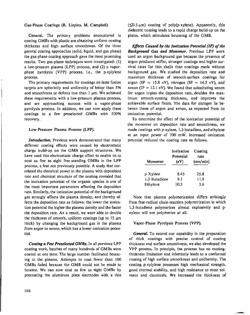
Gas-Phase Coatings (R. Liepins. M. Campbell)
General. The primary problems encountered in
coating GMBs with plastic are obtaining uniform coating
thickness and high surface smoothness. Of the three
general coating approaches (solid, liquid, and gas phase)
the gas-phase coating approach gave the most promising
results. Two gas-phase techniques were investigated: (1)
a low-pressure plasma (LPP) process, and (2) a vapor-
phase pyrolysis (VPP) process, i.e., the p-xylylene
process.
The primary requirements for coatings on laser fusion
targets are sphericity and uniformity of better than 5%
and smoothness or defects less than 1 Lm. We achieved
these requirements with a low-pressure plasma process,
and are approaching success with a vapor-phase
pyrolysis process. In addition, we can now apply these
coatings to a few preselected GMBs with 100V0
recovery.
Low-Pressure Plasma Process (LPP).
Introduction. Previous work demonstrated that many
different coating effects were caused by electrostatic
charge build-up on the GMB support structures. We
have used this electrostatic charge effect to enable us to
coat as few as eight free-standing GMBs in the LPP
process, a feat not previously possible. A study that cor-
related the electrical power in the plasma with deposition
rate and chemical structure of the coating revealed that
the ionization potential of the organic species is one of
the most important parameters affecting the deposition
rate. Similarly, the ionization potential of the background
gas strongly affects the plasma density, and thereby af-
fects the deposition rate as follows: the lower the ioniza-
tion potential the higher the plasma density and the faster
the deposition rate. As a result, we were able to double
the thickness of smooth, uniform coatings (up to 15 ~m
thick) by changing the background gas in the plasma
from argon to xenon, which has a lower ionization poten-
tial.
Coating a Few Preselected GMBs. In all previous LPP
coating work, batches of many hundreds of GMBs were
coated at one time. The large number facilitated bounc-
ing in the plasma. Attempts to coat fewer than 100
GMBs failed because the GMB could not be made to
bounce. We can now coat as few as eight GMBs by
precoating the aluminum plate electrodes with a thin
(SO.5-~m) coating of poly(p-xylene). Apparently, this
dielectric coating leads to a rapid charge build-upon the
plates, which stimulates bouncing of the GMB.
EJects Caused by the Ionization Potential (IP) qfthe
Background Gas and Monomer. Previous LPP work
used an argon background gas because the presence of
argon produced stiffer, stronger coatings and higher sur-
vival rates for thin shells than coatings made without
background gas. We studied the deposition rate and
maximum thickness of smooth-surface coatings for
argon (IP = 15.8 eV), nitrogen (IP = 14.5 eV), and
xenon (IP = 12.1 eV). We found that substituting xenon
for argon triples the deposition rate, doubles the max-
imum smooth-coating thickness, and improves the
achievable surface finish. The data for nitrogen lie be-
tween those of argon and xenon, as expected from its
ionization potential.
To determine the effect of the ionization potential of
the monomer on deposition rate and smoothness, we
made coatings with p-xylene, 1,3-butadiene, and ethylene
at an input power of 700 mW. Increased ionization
potential reduced the coating rate as follows.
Ionization Coating
Potential rate
Monomer (eV) (nrn/min)
p-Xylene 8.45 25.8
1,3-Butadiene 9.1 11.9
Ethylene 10.5 3.6
Note that plasma polymerization differs strikingly
from free-radical chain-reaction polymerization in which
1,3-butadiene polymerizes almost explosively and p-
xylene will not polymerize at all.
Vapor-Phase Pyrolysis Process (VPP).
General. To extend our capability in the preparation
of thick coatings with precise control of coating
thickness and surface smoothness, we also developed the
VPP process. In principle, the process has no coating-
thickness limitation and inherently leads to a conformal
coating of high surface smoothness and uniformity. The
coating p-xylylene possesses high mechanical strength,
good thermal stability, and high resistance to most sol-
vents and chemicals. We increased the thickness of
102
—

coatings on GMBs to greater than 350 ~m, with surface
smoothness approaching 100 nm. This coating can be
applied to mandrels that are etched out through a small
hole, thus leaving free-standing shells with aspect ratios
greater than 22 and wall thicknesses at least as thin as 20
~m. We also installed a gas-jet levitator in a VPP ap-
paratus and coated some levitated GMBs.
Thick, Smooth Coatings. To apply thick coatings, a
cold chamber with a wide temperature and gas-flow
capability was constructed (Fig. VI- 11). Coating deposi-
tion rates from 40 to 500 nm/min and deposition
temperatures from 283 K (+ 10”C) to 238 K (–35”C)
were explored. Deposition rate ‘has a direct effect on the
coating surface smoothness—the higher the rate, the
rougher the surface. By going from a deposition rate of
180 nm/min to 40 nm/min, the surface roughness
decreases from + 1 ~m to <+0.05 ~m. Thus, in prepar-
ing very thick coatings a compromise must be made
among coating thickness, surface smoothness, and
deposition time. Typically, a 100-~m-thick coating with
a 1-pm peak-to-valley surface roughness can be obtained
in 8 h. A GMB with an 86-pm-thick coating of p-
xylylene applied at a rate of 177 nm/min and showing 1-
~m surface smoothness is illustrated in Fig. VI-12.
MONOMER
+,,
rih
4“P.———--l lkL
’11-VACUUM
Fig. VI-II.
Schematic of vapor-phase pyrolysis (VPP) coating
apparatus used to obtain thick (>350-@,
ultrasmooth (k100-nm) coatings on GMBs.
Fig. VI-12.
Scanning-electron micrograph of the surface of an
86-pm-thick VPP plastic coating &posited at 177
nmlmin. 5000X
We found two techniques that will improve surface
finish even at high deposition rates. One uses a co-
monomer that interferes with the crystallization process
and the other uses a substrate coating with a relatively
low number of nucleating sites. Addition of the co-
monomer 2-chloro-p-xyly lene to p-xylylene dramatically
improves surface finish even at high coating rates. Figure
VI- 13 shows an 87-~m-thick coating polymerized with
33 wt’Yo of the above comonomer at a rate 1.9 times
faster than the coating in Fig. VI-12. To obtain an
equivalently smooth surface with only a single monomer,
we would have to use a deposition rate less than 40
nm/min, which is eight times slower than the co-
monomer rate used for the coating shown in Fig. VI-12.
A similar, but somewhat less effective smoothing can be
achieved by applying a smooth aluminum coating to the
GMB before plastic deposition. A GMB mounted on an
Aramid fiber was coated with 20 nm of sputtered
aluminum and then with 41 ~m of p-xylylene at a rate of
150 nm/min. The resulting surface (shown in Fig. VI-14)
is better than that of a similar coating on a bare GMB
(Fig. VI- 12) but not as smooth as a comonomer deposi-
tion (Fig. VI- 13).
Plastic Coatings on Levitated GMBs (with A. Lowe
and C. Ho.#ord). TO coat VPP plastic on a GMB for
20XLD targets, we must mount the GMB on an Aramid
103
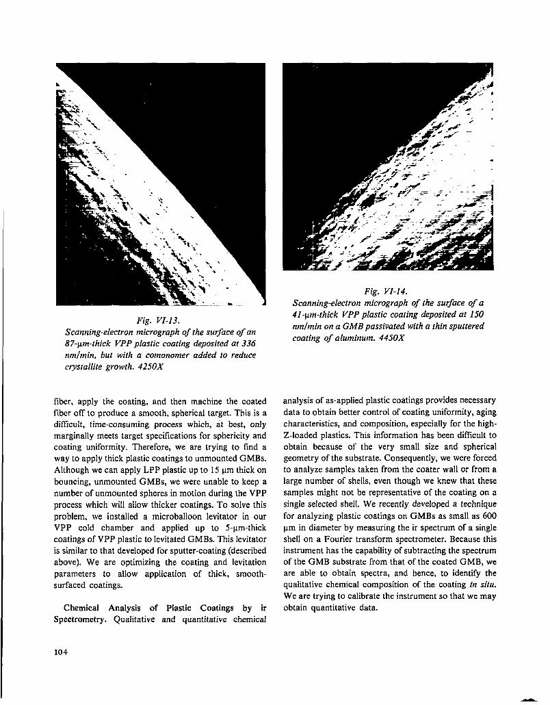
Fig. w-l.?.
Scanning-electron micrograph of the surface of an
87-pm-thick VPP plastic coating deposited at 336
nmlmin, but with a comonomer added to reduce
c~stallite growth. 4250X
fiber, apply the coating, and then machine the coated
fiber off to produce a smooth, spherical target. This is a
ditlicult, time-consuming process which, at best, only
marginally meets target specifications for sphericity and
coating uniformity. Therefore, we are trying to find a
way to apply thick plastic coatings to unmounted GMBs.
Although we can apply LPP plastic up to 15 ~m thick on
bouncing, unmounted GMBs, we were unable to keep a
number of unmounted spheres in motion during the VPP
process which will allow thicker coatings. To solve this
problem, we installed a microballoon levitator in our
VPP cold chamber and applied up to 5-~m-thick
coatings of VPP plastic to levitated GMBs. This levitator
is similar to that developed for sputter-coating (described
above). We are optimizing the coating and levitation
parameters to allow application of thick, smooth-
surfaced coatings.
Chemical Analysis of Plastic Coatings by ir
Spectrometry. Qualitative and quantitative chemical
Fig. VI-14.
Scanning-electron micrograph of the surface of a
41-pm-thick VPP plastic coating deposited at 150
nmlmin on a GMB passivated ~“th a thin sputtered
coating of aluminum. 4450X
analysis of as-applied plastic coatings provides necessary
data to obtain better control of coating uniformity, aging
characteristics, and composition, especially for the high-
Z-loaded plastics. This information has been difficult to
obtain because of the very small size and spherical
geometry of the substrate. Consequently, we were forced
to analyze samples taken from the coater wall or from a
large number of shells, even though we knew that these
samples might not be representative of the coating on a
single selected shell. We recently developed a technique
for analyzing plastic coatings on GMBs as small as 600
~m in diameter by measuring the ir spectrum of a single
shell on a Fourier transform spectrometer. Because this
instrument has the capability of subtracting the spectrum
of the GMB substrate from that of the coated GMB, we
are able to obtain spectra, and hence, to identify the
qualitative chemical composition of the coating {n situ.
We are trying to calibrate the instrument so that we may
obtain quantitative data.
104
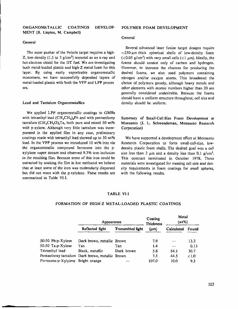
ORGANOMETALLIC COATINGS DEVELOP-
MENT (R. Liepins, M. Campbell)
POLYMER FOAM DEVELOPMENT
General
General
The outer pusher of the Polaris target requires a high-
Z, low-density (1.3 to 3 g/cm3) material as an x-ray and
hot-electron shield for the DT fuel. We are investigating
both metal-loaded plastic and high-Z metal foam for this
layer. By using easily vaporizable organometallic
monomers, we have successfully deposited layers of
metal-loaded plastic with both the VPP and LPP proces-
ses.
Lead and Tantalum Organometallics
We applied LPP organometallic coatings to GMBs
with tetraethyl lead (CHqCH~dPb and with pentaethoxy
tantalum (CH3CH20)~Ta, both pure and mixed 50 wt?40
with p-xylene. Although very little tantalum was incor-
porated in the applied film in any case, preliminary
coatings made with tetraethyl lead showed up to 30 wtOA
lead. In the VPP process we introduced 10 WYOiron via
the organometallic compound ferrocene into the p-
xylylene vapor stream and observed 9.30/0 iron inclusion
in the resulting film. Because some of this iron could be
extracted by soaking the film in hot methanol we believe
that at least some of the iron was molecularly dispersed
but did not react with the p-xylylene. These results are
summarized in Table VI-I.
Several advanced laser fusion target designs require
-250-y m-thick spherical shells of low-density foam
(<0.05 g/cm3) with very small cells (< 1 urn). Ideally, thefoams should consist only of carbon and hydrogen.
However, to increase the chances for producing the
desired foams, we also used polymers containing
nitrogen and/or oxygen atoms. This broadened the
choice of polymers greatly, although heavy metals and
other elements with atomic numbers higher than 20 are
generally considered undesirable. Because the foams
should have a uniform structure throughout, cell size and
density should be uniform.
Summary of Small-Ceil-Size Foam Development at
Monsanto (J. L. Schwendeman, Monsanto Research
Corporation)
We have supported a development effort at Monsanto
Research Corporation to form small-cell-size, low-
density plastic foam shells. The desired goal was a cell
size less than 2 ~m and a density less than 0.1 g/cm3.
This contract terminated in October 1978. Three
materials were investigated for meeting cell size and den-
sity requirements in foam coatings for small spheres,
with the following results.
TABLE VI-I
FORMATION OF HIGH-Z METAL-LOADED PLASTIC COATINGS
CoatingMetal
Appearance Thickness (Wt%)
Reflected light
50:50 Pb:p-Xylene
50:50 Ta:p-Xylene
Tetraethyl lead
Pentaethoxy tantalum
Ferrocene:p-Xyly lene
Dark brown, metallic
Tan
Black, metallic
Dark brown, metallic
Bright orange
Transmitted light (~m) Calculated Found
Brown 7.9 --- 13.3
Tan 1.4 --- 0.13
Dark brown 5.8 64.1 30.7
Brown 7.3 44.5 <1.0--- 107.0 10.0 9.3
105

Evaluation of cellulose acetate asymmetric
membranes proved that these foam films have the re-
quired small cell size. These films can be prepared at
room temperature and lend themselves to molding parts
in matched positive-pressure molds and, possibly, to
vacuum-forming of the desired foam shells. However, we
were unable to produce these foams in the desired den-
sity range. At present, 250-~ m-thick cast foam films,when dried, are 70 to 80 ~m thick, with 2.O-~m and
smaller cells and a density greater than 0.30 g/cm3.
Aropol water-extended polyester foam systems (WEP
66 I-P@ and D-WEP 123@) were also evaluated as a
possible means of forming small-cell-size foams. We suc-
ceeded in making water-extended polyester foams with a
density as low as 0.12 g/cm3, but failed to form foams
having cell sizes less than the required maximum of 2.0
~m. We could mold these foams into small spheres.
Gelatin/water/toluene emulsion foams were also in-
vestigated. Upon film draw-down, foams of small cell
size were produced. However, work on this material was
stopped because of concern as to the reproducibility of
the properties of gelatin and its relatively low thermal
stability.
As a result of the failure of all experiments in this con-
tract, we are reconsidering alternative possibilities for
malting foams that meet requirements for both density
and cell size and using pressurized gas in place of foam
for the buffer.
CRYOGENIC TARGET DEVELOPMENT (J. R. Mil-
ler)
General
Laser fusion targets fueled with cryogenic liquid or
solid DT offer the advantage of high initial fuel density
without the disadvantage of diluent atoms being present
as they are in room-temperature solids having a high
hydrogen density [e.g., lithium in Li(D,T), carbon in
(-CDT)n, or boron and nitrogen in NH,BH,]. In addi-
tion, calculations indicate that the yields from targets
fueled with liquid or solid DT can be considerably higher
than those from targets of the same design, but fueled
with high-pressure DT gas. Therefore, we actively pur-
sued the development of cryogenic targets despite the
significant experimental complications encountered in
their fabrication and in their use in laser-target interac-
tion experiments. We also tested a cryogenic insertion
mechanism for loading and cooling these targets in the
Helios target chamber.
Cryogenic targets receiving the greatest attention are
uniform, hollow shells of solid DT condensed onto the
inside surface of a glass or metal microballoon that
serves as the pusher shell. We previously developed
techniques to freeze the DT into a uniformly thick layer
on the inside surface of the glass and to measure the
thickness uniformity of the condensed DT shell. Because
high-yield targets require metal pusher shells and we are
not able to directly measure the uniformity of DT layers
inside opaque shells, we made a calculational analysis of
the FIF technique.
Fast Isothermal Freezing (FIF) (J. R. Miller, W. J.
Press, R. J. Fries)
The investigation of any possible limitations of the
fast isothermal freezing (FIF) technique for producing
uniform, solid DT layers in target fuel cores continued.
As reported in LA-6616-PR and LA-6834-PR, the FIF
method forms layers of solid DT on the inner surface of
bare GMB fuel cores with a uniformity that is better
than can be determined interferometrically ( + 10°Avariation in layer thickness). Because laser fusion targets
of advanced design have multiple shells and multiple
layers around the cryogenic fuel core, we continued the
investigation of inherent limitations that may apply to
the FIF technique.
Because it is not possible to measure the solid DT
layer’s uniformity in opaque, multishell targets in-
terferometrically, and because no other diagnostic
techniques are available to measure the uniformity of a
thin, low-Z shell (DT) inside one or more opaque high-Z
shells (gold, for example), we developed a computer
model to calculate how long liquid exists in the fuel core
as it is cooled. This time can then be used to predict the
gravitationally induced nonuniformity (NU) produced in
the frozen DT shell.The NU produced in the frozen DT shell, defined as
the difference between the maximum and minimum shell
thicknesses divided by the average shell thickness, de-
pends on the length of time liquid is present in a given
fuel core. For example, a 100-~m-diam fuel core filled
with DT to 10 MPa and frozen in 25 ms, or a 500-~m-
diam fuel core tilled to 10 MPa and frozen in 100 ms will
each produce a NU of 0.095.2 Our heat-flow model
106

calculates the cooling rate of the fuel core, and hence, the
expected thickness uniformity of the solid DT layer.
Although laser fusion targets are radially symmetric
and therefore can be modeled mathematically in one
dimension, the cooling rate of a multishell target cannot
be solved analytically. This inability stems from the
strong temperature-dependence of both the thermal con-
ductivity and the speci!ic heat of most materials over the
temperature range of 4 to 40 K and from the thermal in-
teraction of each layer in a multimaterial target.
The problem of calculating the length of time liquid ex-
ists in a fuel core can be separated into two parts. The
first part consists of determining the time required to
condense all the DT gas into a liquid shell, and the se-
cond part, determining the time required to freeze this li-
quid shell. The sum of these two times is the quantity
used to predict the NU of the frozen DT shell. Physical-
ly, this partition of the problem assumes that the heat
released by the condensing gas prevents the liquid from
cooling below the triple point until all the DT has con-
densed.
An exact numerical solution to the heat equation for
gas condensation in a multishell sphere with
temperature-dependent thermal properties was obtained
from a standard finite-difference formulation.314 Stable,
physically realistic results for all times were obtained
with a Crank-Nicholson scheme using a time-dependent
weighting factors With a constantly spaced nodal mesh,
the transient target temperature distribution had minimal
dependence on the time step used. Therefore, incorpora-
tion of a variable time step into the finite-difference
scheme had the added benefit of minimizing the com-
putational effort. Less than 1 min of CDC 6600 cpu
(central processing) time was needed for each multishell
target evaluated.
The numerical solution for the DT condensation time
in a simple two-shell target is shown in Fig. VI-15. The
family of curves, reduced temperature vs reduced radius,
plots the condensation time of DT gas in a 100-~m-diam,
1-~m-thick glass fuel core positioned inside a second 1-
~m-thick glass shell, The target, initially at T, = 40 K,
cools to T~ = 19.7 K in 63 ms. In general, thicker shells
or larger target diameters increase the DT condensation
time.
Because the DT condensation time is strongly affected
by the helium diffusivity, and because thermal-property
data for cryogenic, gaseous helium at low pressures are
scarce,c the temperature-dependence of the thermal dif-
fusivity for helium was obtained by matching calculated
Lo
.9
.8
::.7
1- 1=,,
*,6
ucc .5?
2 ,4&
z .3e
.2
.1
n.-.0 I .2 .3 .4 .5 .6 .7 .8 .9 1.
RADIUS* =;
Fig. VI-15.
DT condensation-time calculation for a target with
two concentric glass shells separated by 50 pm of
helium exchange gas. the temperature of the DT is
plotted against radia[ position.
and experimental results of the freezing time for a bare
100-~m-diam glass fuel core. The condensation time is
also a function of the density of the gaseous helium.
Although metal shells are not considered in Fig. VI-
15, condensation-time results for such shells were ob-
tained. The effect on condensation time of adding a metal
shell is minimal: no significant time increase is seen
because of the relatively high thermal conductivity y of
metals compared to that of other target materials.
The time required to freeze a liquid DT shell is the se-
cond part of the liquid-existence-time problem. As stated,
when the freezing time is added to the condensation time,
we can predict the layer nonuniformity of solid DT in a
target fuel core.
An approximate solution to the heat-flow problem in-
volving a liquid-solid phase change in spherical bodies
has been formulated.’ This approximate solution was
used to compute freezing times of liquid DT shells. The
results of this calculation indicate that the DT fusion
time is short (<1 ms) compared to typical DT condensa-
tion times (> 10 ins). Consequently, layer nonunifor-
mities arise during the DT condensation time rather than
during the DT solidification time.
Model calculations were performed to determine the
length of time liquid DT is present during the formation
of cryogenic laser fusion targets. Our results make it pos-
sible to predict the thickness uniformity of solid DT
107

shells in opaque, multishell targets. As shown, gas con-
densation occurs at a much slower rate than does the
subsequent solidification of the liquid shell.
Helios Cryogenic Target-Producing Prototype (J. R.
Miller, J. K. Feuerherd, H. E. Tucker, C. Cummings, R.
Day)
The experimental apparatus designed to produce
cryogenic targets for the Helios laser system was tested
extensively. Three specific areas investigated were (1) the
heat load to the apparatus, (2) the cryogenic-shroud
retraction system, and (3) the seals between the target
mount and the cryogenic shroud.
To cool the apparatus to the desired 6 K, we had to
redesign the liquid-helium transfer system, the thermal
standoff between the target mount, the target cart, and
the target holder. In addition, a new cryogenic-shroud
retraction system was designed, fabricated, and as-
sembled. Evaluation of the performance of this device
with high-speed motion pictures, discrete position sen-
sors, and an accelerometer showed that it needs 6.8 ms
to move the required 3 cm. We expect this time to be suf-
ficiently short. However, work is continuing on the
shock-absorber subsystem needed to stop the rapidly
moving cryogenic-shroud retraction device with uniform,
constant deceleration, which is needed to minimize
mechanical fatigue in the entire system and vibration in
the Helios target chamber.
REFERENCES
1.
2.
3.
4.
5.
6.
7.
F. Skoberne, Comp., “Inertial Fusion Program,
January 1—June 30, 1978,” Los Alamos Scientific
Laboratory report LA-7587-PR (May 1980).
Extrapolated from T. M. Henderson, R. J. Simms,
and R. B. Jacobs, “Cryogenic Pellets for Laser-
Fusion Research—Theoretical and Practical Con-
siderations,” Adv. Cryog. Eng. 23, 682 (1977).
M. N. Ozisik, Bounda~ Value Problems of Heat
Conduction (International Textbook Co., 1968), p.
413.
B. Carnahan, H. A. Luther, and J. O. Wilkes, Applied
Numerical Methods (John Wiley and Sons, Inc.,
1969), 462.
S. V. Patonkar and B. R. Baliga, “A New Finite/Dif-
ference Scheme for Parabolic Differential Equations:’
Numerical Heat Transfer 1, 27 (1978).
D. C. Pickles and B. Colyer, “Heat Transfer Through
Low Pressure Helium Gas at Temperatures Below 4.2
K,” Rutherford High Energy Laboratory report
RHEL/R 145 (1967).
Sung Hwang Cho and J. E. Sudderland, “Phase
Change of Spherical Bodies;’ J. Heat Mass Transfer
13, 1231 (1970).
108

VII. APPLICATIONS OF LASER FUSION—FEASIBILITY AND SYSTEMS
STUDIES
(L. A. Booth and T. G. Frank)
Our feasibility and systems studies are being performed to analyze the technical
feasibility and economic aspects of various commercial and military applications of
lasers and laser fusion. Commercial applications include electric power generation,
fissile-fuel production from fusion-fission hybrid reactors, and production of synthetic
fuels such as hydrogen. Our studies also include assessments of advanced technologies
that require development for the ultimate commercialization of laser fusion. The general
objectives of these studies are the conceptualization and preliminary engineering assess-
ment of laser fusion reactors and other energy production subsystems; the development
of computer models of integrated plant systems for economic and technology tradeoff
and comparison studies; and the identification of problems requiring long-term develop-
ment efforts.
REACTOR DESIGN STUDIES
Introduction
Our reactor design studies determine the fundamental
engineering feasibility of reactor design concepts and es-
tablish scaling laws for the sizing of reactors in in-
tegrated plant designs for energy production applica-
tions. In converting pellet output energy to useful forms,
two primary design considerations prevail: (1) protection
of the reactor chamber structural wall from x rays and
ion debris generated by the pellet, and (2) conversion of
these energy forms and of the high-energy neutrons to
useful energy while producing the fuel constituent,
tritium.
In general, these design considerations are essentially
independent of each other. Because -80Y0 of the pellet
output is in the form of high-energy neutrons, this energy
is most conveniently converted to thermal energy in a
“blanket” surrounding the cavity and containing lithium
or lithium compounds for tritium breeding; the design of
this blanket is essentially not dependent upon the first-
wall protection scheme. Likewise, means of protecting
the first wall are generally not dependent upon the
blanket design. Therefore, a variety of blanket designs
can be incorporated with a particular wall-protection
scheme and vice versa.
We are studying three methods of first-wall protec-
tion: (1) a lithium wetted wall,l (2) a magnetically
protected wall with a low-Z sacrificial Iiner,z and (3) a
magnetically protected wall with a background fill gas.
In the lithium wetted-wall concept, the x-ray output and
ion debris are absorbed by the ablation of a thin film of
lithium that coats the inside surface of the first wall. In
the second concept, the ion debris is ducted out the ends
of a cylindrical configuration where the ions are either
collected on large surface areas or slowed down by
MHD decelerators. The x-ray energy is absorbed by
ablation of small amolmts of the low-Z sacrificial liner.
In the third concept, the ion debris is converted in the
same manner as above, but the x-ray energy is at-
tenuated and converted into a blast wave, which
beneficially increases the interaction time of this energy
fraction with the first wall.
Our studies of blanket concepts include (1) a low-
temperature (< 1000 K) liquid-lithium blanket for electric
power generation, (2) a high-temperature ( 1500-2000 K)
boiling-lithium blanket for high-efficiency electric power
generation and as a high-temperature process heat
source for hydrogen production, and (3) a lithium-cooled
array of elements containing fertile 238U and/or 232Th for
the production of fissile fuel and electricity as a
byproduct.
Reported below are results from our studies on the
magnetically protected wall concept, on the high-
temperature boiling-lithium blanket concept, and on a
low-power-density fissile-fuel production blanket
(hybrid) concept.
109

Magnetically Protected Cavity Phenomena Modeling (I.
O. Bohachevsky, J. J. Devaney)
We have programmed the mathematical description
of the new plasma model representing the magnetically
protected reactor cavity for use on the CRAY computer.
The part of the code that solves the coupled ion-
transport and electromagnetic field equations has been
tested successfully; the part describing the behavior of
the continuum background medium is being tested. In
addition to completing these time-consuming tasks, our
theoretical analysis has led to an improved under-
standing of the physics of cavity phenomena and of
implications of the postulated cylindrical symmetry.
We have derived expressions for the momentum
transfer from the high-velocity ions to the background
medium. Some results are summarized in Table VII-I,
where we have used rl as the drag force in dynes acting
on an alpha particle moving with the energy E(keV)
through helium at the density of pg/cm3. Although our
expressions are currently valid only for neutral gases,
their use may be justified in cases of low background
ionization. In addition, their availability in a form
suitable for computation enables us to test the code and
provides assurance that additional results will be derived
when needed.
MHD Decelerators for the Magnetically Protected Wall
Concept (I. O. Bohachevsky)
The use of structured pellets in inertial confinement fu-
sion (ICF) reactors and of a buffer gas for cavity wall
protection’ implies that a significant fraction of fuel-
pellet microexplosion energy will be deposited in the
cavity environment. Therefore, there is a need to in-
vestigate methods of removing and recovering this
energy. Calculations indicate that the sputtering erosion
of energy sinks,s’6 proposed for the removal of pellet-
debris ion energy in the magnetically protected reactor
cavity design, may be unacceptably high. Consequently,
we had to seek alternative methods. We found that the
energy may be removed and recovered from the pellet
debris and the cavity medium by means of magnetic
fields in a magnetohydrodynamic (MHD) energy con-
verter that decelerates the ions without suffering exces-
sive wall erosion and that even generates electric energy
in the process.
Previous studies’ assessing the applicability of MHD
generators for energy removal from the fusion fuel-pellet
debris led to a more extensive analysis8 of these devices,
as summarized below.
There are conventional and induction-type MHD
generators. In a conventional generator, the electrodes
TABLE VII-I
DRAG FORCE ON AN ALPHA PARTICLE IN
HELIUM AT DENSITY pg/cm3
r, = p x 2.4113 x 10⁻⁴
S.= ~{n 1 + 1“3 ~ ’05+ 0.04407E
S, = 0.58 E0.59
S=$+SHSL
s=SH + SL
SHSLs=
SH + SL+ AS
S=2
E (keV) 50 40
AS 0.10 0.15
E > 10 MeV
50 keV s E s 10 MeV
5keVSE<50keV
lkeV<E<5keV
30 20 10 8 5
0.20 0.33 0.50 0.60 0.70
110

are exposed to the high-energy plasma flow and therefore
tend to be eroded rapidly. In an induction-type
generator, the power is extracted with induction coils
located behind insulating refractory walls, which,
therefore, are not exposed to the destructively hot plasma
environment.
The plasma exiting from the reactor differs from that
in a conventional MHD generator in two respects. (1) Its
conductivity is very high because it contains a large
proportion of metallic ions in high ionization states, and
(2) it can be collimated with the magnetic field into a
high-velocity beam.s’g Consequently, the magnetic
Reynolds number in the MHD channel will be high (> 1)
and the energy density will not be less than in a conven-
tional (electrode) generator. These conditions make it
possible to exploit the engineering advantages of the
induction-type generator without penalties commonly as-
sociated with low-energy density and efllciency if a con-
ventional combustion-generated plasma is used in this
device.
To investigate the compatibility of magnetically
protected reactor cavity designs with MHD generators
we imposed two performance requirements. (1) The
generators should reduce the ion exit velocity so that the
debris, possibly with the aid of diffusers, could be used in
conventional heat exchangers, and (2) they should
generate sufficient amounts of electricity to energize their
own magnets.
In our analysis we solved the one-dimensional
channel-flow equations, determined the magnet
parameters, and estimated the cost of MHD decelera-
tion. Representative results summarized in Tables VII-II
and -HI and in Figs. VII-1 and -2 show that nearly 65%
of the ion kinetic energy has been either extracted in the
form of electric power or converted into thermal energy.
In our illustrations, Q1p~ALdenotes the power residing in
the moving plasm?, Q~~c is the power dissipated in
magnet coils, and QICP is the power developed in the in-
duction coil for an arbitrarily prescribed load current of
500 A. None of the cases calculated was optimized in
any way, and therefore, significant improvement in per-
formances can be gained by simple parameter improve-
ment.
To determine the economic effectiveness of MHD
decelerators, we compared their cost with the cost of
graphite energy sinks. It is convenient to arrive at the
decelerator cost by estimating the magnet and channel
costs separately. The cost estimate for a conventional
magnet (including core, winding, cooling, and some sup-
port structure) is based on a unit cost of 100000 $/m3;
TABLE VII-H
CONSTANT-AREA SUPERSONIC DECELERATOR
0.35- by 0.35- by l.00-m CHANNEL
Casea
1 2 3
Plasma Conductivity (mho/m) 1000 500 100
Magnetic Field (T) 0.134 0.219 0.576
Exit Velocity (m/s) 5784 5767 5812
Exit Pressure (N/m2) 1.94x 10s 1.81 X 10s 1.95x 10s
Exit Mach Number 1.007 1.001 1.006
Ideal Power (W) 5.35 X 10⁴ 3.62 X 10⁴ 1.01 X 10⁴
———‘In all cases:
Instantaneous Mass Flow Rate(kg/s)
Pulse Rate (Hz)Ion Pulse Duration (s)
Inlet Velocity (m/s)
Inlet Pressure (N/mz)
5101.24 X 10A
104
10’
111
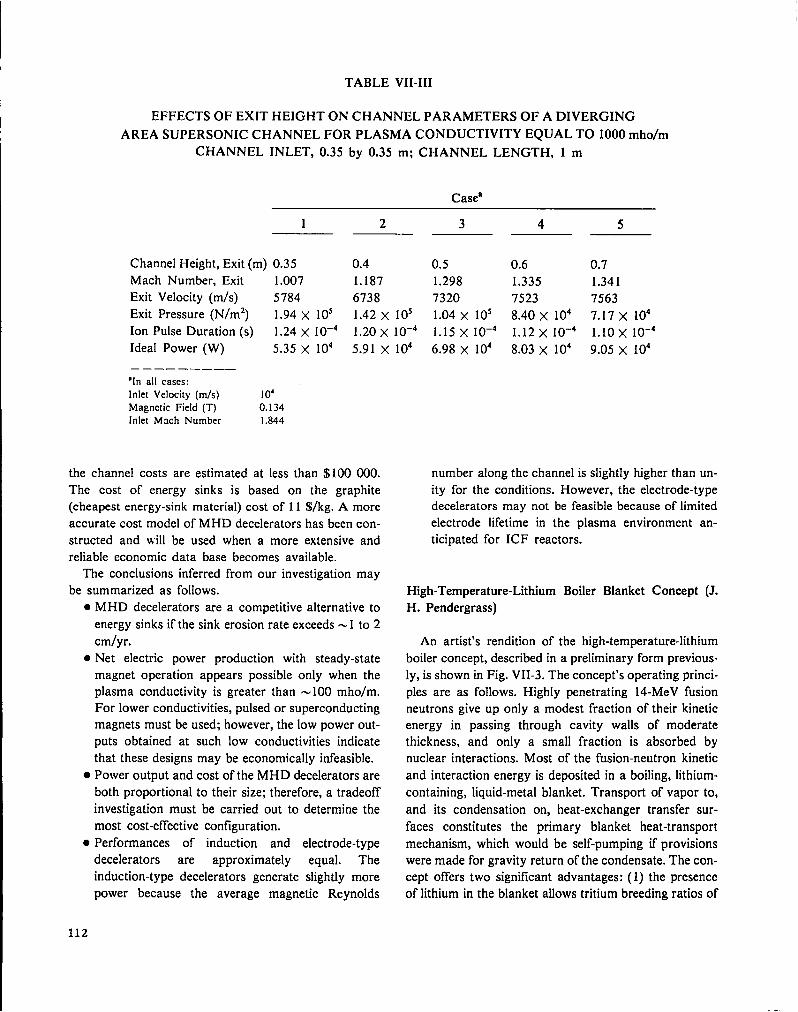
TABLE VII-III
I EFFECTS OF EXIT HEIGHT ON CHANNEL PARAMETERS OF A DIVERGING
AREA SUPERSONIC CHANNEL FOR PLASMA CONDUCTIVITY EQUAL TO 1000 mho/m
CHANNEL INLET, 0.35 by 0.35 m; CHANNEL LENGTH, 1 m
Casea
1 2 3 4 5
Channel Height, Exit (m) 0.35 0.4 0.5 0.6 0.7Mach Number, Exit 1.007 1.187 1.298 1.335 1.341Exit Velocity (m/s) 5784 6738 7320 7523 7563Exit Pressure (N/m2) 1.94 x 10⁵ 1.42 X 10s 1.04 x 10s 8.40 X 10⁴ 7.17 x 10⁴Ion Pulse Duration (s) 1.24 X 10⁻⁴ 1.20x 10⁻⁴ 1.15 X 10⁻⁴ 1.12x 10⁻⁴ 1.1OX 10-4
Ideal Power (W) 5.35 x 10⁴ 5.91 x 10⁴ 6.98 X 10⁴ 8.03 X 10⁴ 9.05 x 10⁴
.—— ——— ——“In all cases:
Inlet Velocity (m/s) 104
Magnetic Field (T) 0.134Inlet Mach Number 1.844
the channel costs are estimated at less than $100000.
The cost of energy sinks is based on the graphite
(cheapest energy-sink material) cost of 11 $/kg. A more
accurate cost model of MHD decelerators has been con-
structed and will be used when a more extensive and
reliable economic data base becomes available.
The conclusions inferred from our investigation may
be summarized as follows.
● M HD decelerators are a competitive alternative to
energy sinks if the sink erosion rate exceeds -1 to 2
cmlyr.● Net electric power production with steady-state
●
●
112
magnet operation appears possible only when the
plasma conductivity is greater than -100 mho/m.
For lower conductivities, pulsed or superconducting
magnets must be used; however, the low power out-
puts obtained at such low conductivities indicate
that these designs may be economically infeasible.
Power output and cost of the MHD decelerators are
both proportional to their size; therefore, a tradeoff
investigation must be carried out to determine the
most cost-effective configuration.
Performances of induction and electrode-type
decelerators are approximately equal. The
induction-type decelerators generate slightly more
power because the average magnetic Reynolds
number along the channel is slightly higher than un-
ity for the conditions. However, the electrode-type
decelerators may not be feasible because of limited
electrode lifetime in the plasma environment an-
ticipated for ICF reactors.
High-Temperature-Lithium Boiler Blanket Concept (J.
H. Pendergrass)
An artist’s rendition of the high-temperature-lithium
boiler concept, described in a preliminary form previous-
ly, is shown in Fig. VII-3. The concept’s operating princi-
ples are as follows. Highly penetrating 14-MeV fusion
neutrons give up only a modest fraction of their kinetic
energy in passing through cavity walls of moderate
thickness, and only a small fraction is absorbed by
nuclear interactions. Most of the fusion-neutron kinetic
and interaction energy is deposited in a boiling, lithium-
containing, liquid-metal blanket. Transport of vapor to,
and its condensation on, heat-exchanger transfer sur-
faces constitutes the primary blanket heat-transport
mechanism, which would be self-pumping if provisions
were made for gravity return of the condensate. The con-
cept offers two significant advantages: (1) the presence
of lithium in the blanket allows tritium breeding ratios of

I I 11 I 1 , ,-3
100 500
~ mhom
o
Fig. VII-1.
Effect of conductivity on power allocation for a
constant-area supersonic duct.
1.0 orgreater, hence tritium self-sufflciencyis achieved;
and (2) pure lithium and lithium-containing molten alloys
considered for use have relatively low vapor pressures
(0.4 atm at 1500 K rising to -15 atm at 2000 K for pure
lithium) so that structural requirements are not severe.
The preliminary description of the concept3 listed a
number of potential advantages over other high-
temperature fusion reactor blanket concepts. We have
attempted to further assess the possibility of achieving
these benefits and have developed conceptional solutions
to important design problems.
Design aspects considered include
● The containment of molten lithium-containing al-
loys at elevated temperatures;
. The recovery of most neutron kinetic and interac-
tion energy as high-temperature heat;
‘2r——————10
t
——
J 1 , I , I I
500mho)U-(Y
10
Fig. VIZ-2.
Effect of conductivity on power
diverging-area supersonic duct.
allocation for a
● An allowance for differential thermal expansion and
for routine, periodic replacement of neutron-
damaged first-wall structures while maintaining all
other reactor functions;● The design of the primary heat exchanger, with
emphasis on limiting the tritium escape rates
through primary heat exchangers into power-cycle
or process loops to acceptable values;
. Neutronics and tritium breeding performance;
● The distribution of boiling and steady-state vapor
volume fractions;
● The recovery of bred tritium by methods that take
advantage of high blanket temperatures; and
● Electric power conversion cycles for topping, which
can take advantage of the high heat delivery
temperatures.
As blanket containment structural materials, we con-
sidered ceramics, glass-ceramics, and graphites, all of
which possess the required strength and resistance to
creep in the 1500 to 2000 K temperature range. As a
—
113

FAL
Fig. VIZ-3.
A rtist’s rendition of [ithium boiler high-temperature tritium-breeding blanket and primary heat-tran-
sport concept. (A) Outer containtnent clamshell, (B) boiling lithium, (C) inner lithium-cooled blanket
containment clamshell including wetted- wall first- wall protection, (D) pellet injection tube, (E) laser
beam tube, (F) supersonic condenser, (G) lithium vapor, (H) vapor conduit, (I) process heat or power
cycle heat exchanger, (J) process heat or power cycle stream, (K) condensate return line, (L) j7rst-wall and beam-tube lithium coolant feed,
protection from attack by the liquid metal, we considered
coating these materials with thin adherent layers of TZM
(0.5 :0.08:99.42 wt% Ti:Zr:Mo) or protecting the struc-
ture with thicker, nonadherent TZM liners. Reflux ex-
periments of 1000-h duration at 1923 K indicated that
TZM is not attacked by pure lithium under these con-
ditions.l” First walls operating at blanket temperaturecould permit the recovery of x-ray and pellet debris
energy at high temperature. However, TZM liners, sup-
ported by cooled steel walls with insulation between liner
and structure and possessing sufficient compressive
strength to transmit internal pressure loads to the load-
bearing structure without collapsing, appear more attrac-
tive.
A carbon foam, made by sintering together hollow
spheres manufactured from petroleum pitch, which has a
density 0:0.39 gjcm3, a thermal conductivity y of only
-10-3 W/cm. K, and a compressive strength of 1500
psia at room temperature, has been identified as a poten-
tially attractive insulating material.’l However, lack of
knowledge concerning high-temperature physical proper-
ties and behavior under 14-MeV neutron irradiation to
high fluences compels us to examine other insulation
concepts as well.
Provisions for accommodating differential thermal ex-
pansion and periodic, routine replacement of first-wall
structure are indicated in Fig. VII-3.
Most neutrons passing through the first-wall structure
can be absorbed in a liquid, pure-lithium blanket less
than 2.0 m thick, and tritium breeding ratios greater than
1.5 can be achieved with such thicknesses. However, the
blanket will actually be thicker because of significant
fractional vapor volume. Boiling is expected to be un-
usual because energy is deposited volumetrically rather
than transferred into the blanket through solid surfaces.
114

Because most theory and experiments concerned with or-
dinary nucleate boiling are of limited applicability, ex-
periments will probably be required to clarify this issue.
With liquid-lithium thicknesses of this order of
magnitude, significant amounts of gamma energy,
produced primarily by (n,-y) reactions of neutrons with
reactor structure and blanket fluids, and of neutron
energy can escape from the blanket. While deposition of
as much fusion energy as possible in the high-
temperature zone may be desirable because lower
temperature heat can be used less efficiently, capture of
the last few percent of escaping energy is generally more
diflicult than capture of all the rest. On the other hand,
greater gamma and neutron enekgy leakage means that
thicker reactor shielding and a greater capacity to cool
the shield will be required. Exploratory neutronics
calculations for 1.5-m-thick, 20-vol%-vapor, pure-
Iithium blankets indicate that gamma-energy leakage is
more than 10% of neutron wall loading.
In an attempt to retain more gamma and neutron
energy within the blanket without large increases in
blanket thickness, we investigated the use of lithium-rich
boiling lead-lithium mixtures. Preliminary neutronics
calculations for 1.5-m-thick blankets indicate that
gamma- and neutron-energy leakage can be reduced sub-
stantially, i.e., by a factor of about 2, that the total of
neutron kinetic plus interaction energy is increased, and
that the tritium breeding ratio is relatively insensitive to
lead content up to large lead concentrations. Although
there is little compatibility experience for high-
temperature materials with lead and much less for lead-
lithium mixtures, all indications are that no particular
problems will be encountered. Lead-lithium alloys have
lower vapor pressures than lithium and are projected to
have lower tritium solubilities, thereby further lowering
containment structural stresses and blanket tritium in-
ventories.
Conservative calculations, which assume that the only
significant resistance to tritium permeation through heat
exchangers is that of bulk materials to diffusion, indicate
that the use of double-walled heat-transfer equipment
with ceramic permeation barriers and removal of tritium
escaping through the first wall by a helium sweep gas
between the two walls will limit tritium escape rates to
acceptable levels, i.e., to 1.0 Ci or less per day. The
helium sweep gas also aids heat transfer by providing a
conductive mechanism operating in parallel with thermal
radiation, to which helium is essentially transparent, and
permits ready adjustment of pressure differential loading
between inner and outer walls. Because readily fabricable
metals of acceptable cost creep excessively in the
temperature range of interest, the use of ceramics, glass-
ceramics, and graphites for construction of primary heat
exchangers will probably be necessary. Protection from
blanket fluid attack by coating or cladding such
materials with, e.g., TZM, is necessary. On the process-
fluid side, heat-transfer surfaces must be protected from
attack by oxidizing gas mixtures with oxides, e.g.,
alumina or silica, as structural materials or protective
layers. Double-walled heat-transfer equipment construc-
tion affords both protection against catastrophic heat-
exchanger failure due to sudden rupture and the pos-
sibility of detecting small leaks before they assume
serious proportions. Because the largest resistance to
heat transfer to gaseous process or power-cycle streams
is the gas film resistance, a large temperature-drop
penalty is not paid for double-walled heat-exchanger
construction in such cases.
If permeable windows are used for tritium recovery,
tritium window performance is enhanced by higher
temperatures and their simplicity is attractive. However,
high-temperature distillation can also take advantage of
the high temperatures provided by lithium boiler blankets
and offers other advantages, including the removal of
other volatile blanket impurities such as helium
generated by (n,a) reactions of blanket and structural
materials, oxygen, and nitrogen. Distillation for tritium
recovery has been rejected in the past because at low
temperatures (below -1230 K), the liquid is enriched in
deuterium and protium relative to the vapor. At higher
temperatures the opposite is true, with the atom ratio of
deuterium in the vapor to deuterium in the liquid rising to
10 at -1850 K, corresponding roughly to an enrichment
by a factor of 10 for each equilibrium stage, so that only
a few stages would be required. Also, side-stream
drawoffs of only a few percent of the blanket boilup are
required, heat can be recovered at temperatures only a
little below the blanket operating temperature in
overhead condensers, column shell construction would
be similar to blanket containment, and the device would
be self-pumping.
Preliminary indications are that thermionic diode
designs developed for topping fossil-fuel-fwed steam
power plant s12 can be readily adapted for mating with
lithium boiler blankets to improve overall plant thermal
conversion efficiencies or to provide dc power for
electrochemical processes such as the bismuth-oxide
hybrid cycle described below.
115

Fusion-Fission Hybrid Reactor Studies (W. A. Reupke,
H. S. CuUingford)
Interest in proliferation-resistant fuel cycles has
stimulated the development of hybrid fusion-fission con-
cepts based on the resource-eflicient thorium fuel cycle.
Previous studies have identified a high-power-density
hybrid concept that produces a large amount of
byproduct electricity13 as well as lissile fuel. Our studies
have turned to quasi-symbiotic concepts that maximize
fissile-fuel production and minimize heat
production—so-called fissile-fuel factories. Such con-
cepts shift the burden of electric power production from
the hybrid reactor to a host system of fission reactors.
We have adopted the following conditions as our design
basis: (1) electrical self-sufficiency, (2) tritium self-
suftlciency, and (3) maximum tissile-product output per
unit of blanket heat.
Our studies of fissile-fuel factories are based on laser-
driven ICF reactor concepts, The specific designs in-
vestigated are spherical and use the wetted-wall reactor
cavity, which is enclosed by spherical shells consisting of
breeding materials, coolant, and structure. Liquid lithium
is used as the fertile material for breeding tritium and as
the reactor coolant. The fissile breeding material is
thorium metal.Neutronics calculations were performed with our one-
dimensional S~ code ONETRAN-DA. Multigroup cross
sections and kerma factors were processed fromENDF/B-IV using the NJOY processing system to form
a coupled 30/12 group neutron/gamma-ray set. Several
blanket compositions and configurations were in-
vestigated. Calculated quantities of interest include the
tritium breeding ratio R=, the fissile conversion ratio or
number of fertile atoms converted per thermonuclear
source neutron RE, the blanket energy deposition per
thermonuclear source neutron Q, and the ratio of lissile-
equivalent thermal energy to blanket energy 180 R~/Q.
A typical reactor geometry and blanket composition is
given in Table VII-IV. Selected results of the neutronics
calculations are presented in Table VII-V. Only cases
that satisfy the requirement for tritium self-sufficiency
are included in Table VII-V. For Case 1, a 4-cm-thick
beryllium neutron-multiplier region was included adja-
cent to the reactor cavity and the allowable volume frac-
tion of thorium, while retaining suftlcient lithium coolant
for a tritium breeding ratio of 1.1, was determined. The
fissile breeding region for Case 2 includes the maximum
volume fraction of thorium consistent with requirements
TABLE VII-IV
CARBON-REFLECTED BLANKET
Outside Radius
(cm) Compositiona
199.9
200.0
201.0
230.0
232.0
262.0
282.0
284.0
292.0
296.0
Void
Li
50% Li, 50940 SSb
Li
50% Li, 50% SS
68.6V0 Th, 16.5!40 Li, 14.9V0 SSc50% SS, 50?40 Li
Li
Ss————. ——. —‘Compositions in volYO.bSS = stainless steel.
for structure and coolant. Suftlcient beryllium neutron
multiplier (11 cm) was included to obtain a tritium
breeding ratio of 1.1. Case 3 is similar to Case 2 except
that the beryllium-region thickness was reduced to 4 cm
and sufficient lithium was added between the beryllium
and thorium regions to obtain a tritium breeding ratio of
1.1. For Case 4, the beryllium was eliminated and the
lithium-region thickness was increased sufficiently to ob-
tain an adequate tritium breeding ratio. The effects of us-
ing a carbon reflector outside the fissile breeding region
are illustrated by Case 5 (see also Table VII-IV).
The most attractive designs are Cases 2 through 5.
The use of a beryllium neutron multiplier results in smal-
ler overall systems (Cases 2 and 3) than the design with
sufficient lithium for adequate tritium breeding without
the neutron multiplier (Case 4). For Case 5, the thickness
of the fissile breeding region is reduced from 50 to 30 cm,
but the tissile fuel production per thermonuclear neutron
RF, is almost as large as for Case 4. Thus, the average
rate of production of fissile fuel per unit volume of tissile
blanket is larger by -70V0 for Case 5 than for Case 4.
This may have important implications for optimum
processing cycles.
116
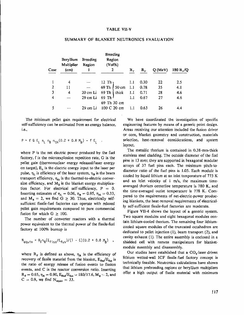
TABLE VII-V
SUMMARY OF BLANKET NEUTRONICS EVALUATION
Beryllium
Multiplier
Case (cm)
1 4
2 11
3 44 ---
5 ---
Breeding
Region
1
..-
---
20 cm L1
29 cm Li
29 cm LI
Breeding
Region
(Vol%)
2 R~ RF Q (MeV) 180 R,/Q
12 Th
I1.1 0.30 22 2.5
69Th 50cm 1.1 0.78 35 4.1
69 Th thick 1.1 0.71 28 4.6
69 Th 1.1 0.67 27 4.6
69 Th 30 cm
100 C 20 cm 1.1 0.63 26 4.4
The minimum pellet gain requirement for electricalself-sufilciency can be estimated from an energy balance,
i.e.,
P = f G EL nL TIB nth(0.2 + 0.8 MB) - f EL .
where P is the net electric power produced by the fuel
factory, f is the microexplosion repetition rate, G is the
pellet gain (thermonuclear energy released/laser energy
on target), EL is the electric energy input to the laser per
pulse, q~ is efficiency of the laser system, ~~ is the beam
transport efficiency, qt~ is the thermal-to-electric conver-
sion efficiency, and MB is the blanket energy multiplica-
tion factor. For electrical self-sufficiency, P = O.
Inserting estimates of q, = 0.06, q, = 0.95, q,~ = 0.33,
and MB = 2, we find G > 30. Thus, electrically self-
sufflcient fiss~e-fuel factories can operate with relaxed
pellet gain requirements compared to pure commercial
fusion for which G > 100.
The number of converter reactors with a thermal
power equivalent to the thermal power of the tissile-fuel
factory at IOOVOburnup is
Nequiv
= @R(Efj#fu~ )/(1 - C)(O.2 + 0.8 MB) ,
where RF is defined as above, q~ is the efficiency of
recovery of !issile material from the blanket, Efl~~/Em~is
the ratio of energy release of fusion events to fission
events, and C is the reactor conversion ratio. Inserting
RF= 0.65, rl~ = 0.90, En,,/Ew, = 180/1 7.6, MB = 2, and
C = 0.9, we find N,quiv = 33.
We have coordinated the investigation of specific
engineering features by means of a generic point design.
Areas receiving our attention included the fusion driver
or core, blanket geometry and construction, materials
selection, heat-removal considerations, and system
layout.
The metallic thorium is contained in 0.38-mm-thick
stainless steel cladding. The outside diameter of the fuel
pins is 13 mm; they are supported in hexagonal modular
arrays of 37 fuel pins each. The minimum pitch-to-
diameter ratio of the fuel pins is 1.05. Each module is
cooled by liquid lithium at an inlet temperature of 773 K
and an inlet veiocity of 1 ~s, the maximum time-
averaged thorium centerline temperature is 780 K, and
the time-averaged outlet temperature is 778 K. Com-
pared to the requirements of net-electric-power produc-
ing blankets, the heat-removal requirements of electrical-
ly self-suficient fissile-fuel factories are moderate.
Figure VII-4 shows the layout of a generic system.
Two square modules and eight hexagonal modules con-
tain lithium-cooled thorium. The remaining four lithium-
cooled square modules of the truncated octahedron are
dedicated to pellet injection (1), beam transport (2), and
cavity exhaust (1). The entire assembly is enclosed in a
shielded cell with remote manipulators for blanket-
module assembly and disassembly.
Our studies have established that a CO#aser-driven
lithium wetted-wall ICF fissile-fuel factory concept is
technically feasible. Neutronics calculations have shown
that lithium prebreeding regions or beryllium multipliers
offer a high output of tissile material with minimum
117
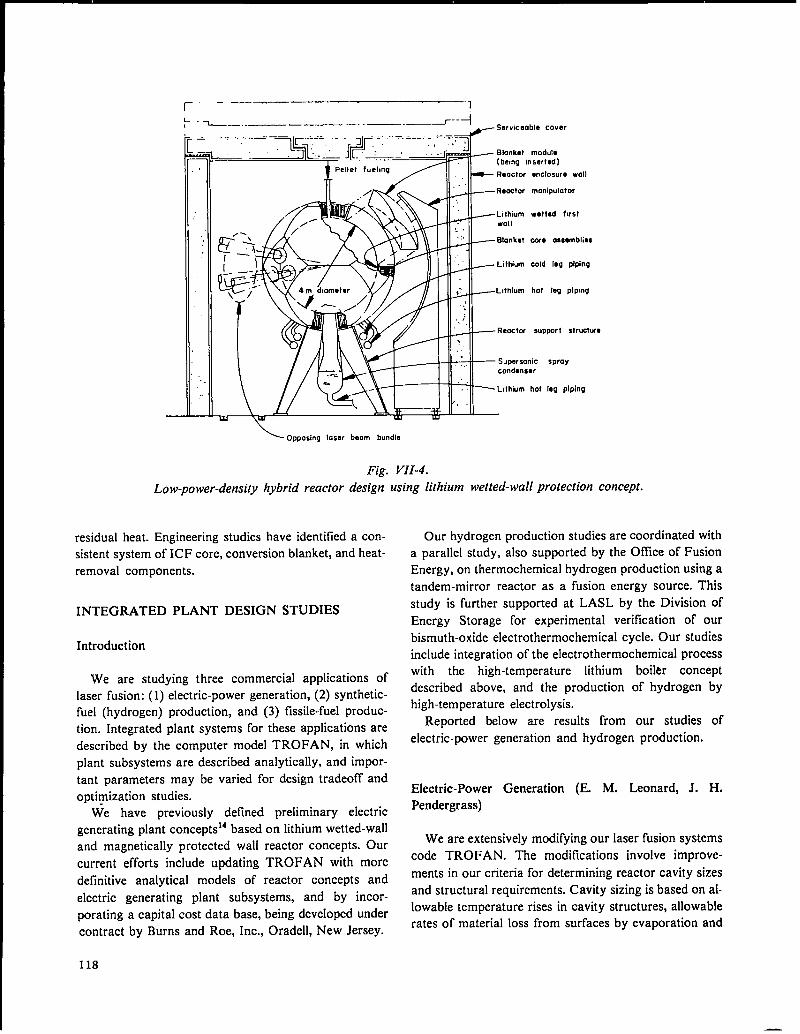
~ ——I
: -1-- ——..—————. —...— —- .—-~ ---i- %rvicaable cover
—
.-. -———— .-— —!-. -.-.= .- -!-. :. ---- - ––--7
modulensertad)
enclosure wall
manipulator
wotte.d first
com ascomblias
cold log plplng
ho? leg plpmg
supper t st ructwa
nic sprayar
hot leg piping
\ Opposing law beam bundle
Fig. VII-4.
Low-power-density hybrid reactor design using lithium wetted-wall protection concept.
residual heat. Engineering studies have identified a con-
sistent system of ICF core, conversion blanket, and heat-
removal components.
INTEGRATED PLANT DESIGN STUDIES
Introduction
We are studying three commercial applications of
laser fusion: (1) electric-power generation, (2) synthetic-
fuel (hydrogen) production, and (3) tissile-fuel produc-
tion. Integrated plant systems for these applications are
described by the computer model TROFAN, in which
plant subsystems are described analytically, and impor-
tant parameters may be varied for design tradeoff and
optimization studies.
We have previously defined preliminary electric14based on lithium wetted-wallgenerating plant concepts
and magnetically protected wall reactor concepts. Our
current efforts include updating TROFAN with more
definitive analytical models of reactor concepts and
electric generating plant subsystems, and by incor-
porating a capital cost data base, being developed under
contract by Burns and Roe, Inc., Oradell, New Jersey.
118
Our hydrogen production studies are coordinated with
a parallel study, also supported by the OffIce of Fusion
Energy, on thermochemical hydrogen production using a
tandem-mirror reactor as a fusion energy source. This
study is further supported at LASL by the Division of
Energy Storage for experimental verification of our
bismuth-oxide electrothermochemical cycle. Our studies
include integration of the electrothermochemical process
with the high-temperature lithium boiler concept
described above, and the production of hydrogen by
high-temperature electrolysis.
Reported below are results from our studies of
electric-power generation and hydrogen production.
Electric-Power Generation (E. M. Leonard, J. H.
Pendergrass)
We are extensively modifying our laser fusion systems
code TROFAN. The modifications involve improve-
ments in our criteria for determining reactor cavity sizes
and structural requirements. Cavity sizing is based on al-
lowable temperature rises in cavity structures, allowable
rates of material loss from surfaces by evaporation and
—
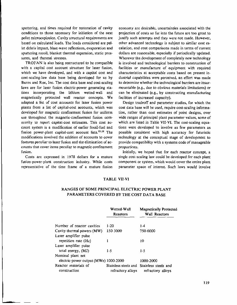
sputtering, and times required for restoration of cavity
conditions to those necessary for initiation of the next
pellet microexplosion. Cavity structural requirements are
based on calculated loads. The loads considered are pel-
let debris impact, blast-wave reflections, evaporation and
sputtering recoil, blanket thermal expansion, static pres-
sures, and thermal stresses.
TROFAN is also being restructured to be compatible
with a capital cost account structure for laser fusion,
which we have developed, and with a capital cost and
cost-scaling-law data base being developed for us by
Burns and Roe, Inc. The cost data base and cost-scaling
laws are for laser fusion electric-power generating sta-
tions incorporating the lithium wetted-wall and
magnetically protected wall reactor concepts. We
adapted a list of cost accounts for laser fusion power
plants from a list of capital-cost accounts, which was
developed for magnetic confinement fusion for uniform
use throughout the magnetic-confinement fusion com-
munity to report capital-cost estimates. This cost ac-
count system is a modification of earlier fossil-fuel and
fission power-plant capital-cost account lists.ls116 The
modifications involved the addition of accounts to cover
features peculiar to laser fusion and the elimination of ac-
counts that cover items peculiar to magnetic confinement
fusion.
Costs are expressed in 1978 dollars for a mature
fusion-power-plant construction industry. While costs
representative of the time frame of a mature fusion
economy are desirable, uncertainties associated with the
projection of costs so far into the future are too great to
justify such attempts and they were not made. However,
other advanced technology is subject to similar cost es-
calation, and cost comparisons made in terms of current
dollars are reasonable, especially if periodically updated.
Wherever the development of completely new technology
is involved and technological barriers to construction of
facilities or manufacture of equipment with required
characteristics at acceptable costs based on present in-
dustrial capabilities were perceived, an effort was made
to determine whether the technological barriers are insur-
mountable (e.g., due to obvious materials limitations) or
can be eliminated (e.g., by constructing manufacturing
facilities of increased capacity).
Design tradeoff and parameter studies, for which the
cost data base will be used, require cost-scaling informa-
tion, rather than cost estimates of point designs, over
wide ranges of principal plant parameter values, some of
which are listed in Table VII-VI. The cost-scaling equa-
tions were developed to involve as few parameters as
possible consistent with high accuracy for futuristic
technology at the conceptual stage of development to
provide compatibility with a systems code of manageable
proportions.
Initially, we hoped that for each reactor concept, a
single cost-scaling law could be developed for each plant
component or system, which would cover the entire plant
parameter space of interest. Such laws would involve
TABLE VII-VI
RANGES OF SOME PRINCIPAL ELECTRIC POWER PLANT
PARAMETERS COVERED BY THE COST DATA BASE
Wetted-Wall
Reactors
Magnetically Protected
Wall Reactors
Number of reactor cavities
Cavity thermal powers (M W)
Laser amplifier pulse
repetition rate (Hz)
Laser amplifier pulse
-20
50-3000
total energy, (MJ) 1-5
Nominal plant net
electric-power output (M We) 1000-2000
Reactor materials of Stainless steels andconstruction refractory alloys
1-4
750-6000
10
1-5
1000-2000
Stainless steels and
refractory alloys
119
scaling relative to a single-point plant design for each
reactor concept. However, large changes in plant
capacity and/or in the number ofreactor cavities within
the ranges of interest necessitated qualitative as well as
quantitative changes in plant layout, plant equipment,
and facility conceptual design. In addition, the ranges of
parameter values for which accepted scaling laws or new
scaling laws developed during the present study are ac-
curate about point designs are quite limited. Therefore,
more than one conceptual point design, plus scaling
about the point designs, for the two reactor concepts
proved necessary for accurate coverage of the entire
parameter space of interest. The point conceptual
designs upon which the scaling laws are based are (1) a
3000-MWt plant with 20 wetted-wall reactor cavities, (2)
a 3000-MWt plant with 4 wetted-wall reactor cavities,
(3) a 3000-MWt plant with 1 wetted-wall reactor cavity,
(4) a 5600-MWt plant with 4 magnetically protected wall
reactor cavities, and (5) a 5600-MWt plant with 1
magnetically protected wall reactor cavity.
Different approaches were used to develop the cost
data for various plant facilities, components, and
systems. For some, especially those peculiar to laser fu-
sion and involving technology that is only in the concep-
tual stage, more detailed conceptual designs were
developed and basic unit material, fabrication, assembly,
and installation costs were estimated. For example, raw-
materials costs for large refractory-metal reactor vessels
were obtained from suppliers, and fabrication, assembly,
and installation costs were based on information from
various manufacturers, reviews of published information,
and Burns and Roe in-house expertise. Fabrication costs
for such vessels include assembly (primarily by welding
using advanced technology such as electron beams or
lasers) of factory-constructed subassemblies in the reac-
tor service building or wing, and final assembly in reac-
tor cells. Because the same facilities and equipment are
required for scheduled maintenance and repair of
damaged equipment, their cost is included in a
maintenance equipment account.
in other cases, e.g., for such relatively conventional
plant equipment as turbine generators and steam
generators, design and cost information was obtained
from manufacturers. Designs for some major plant
systems, e.g., ultimate heat rejection, service cooling
water, chilled water, emergency tritium removal,
radwaste, and building service systems, which are
relatively conventional and insensitive to nuclear island
characteristics, were adapted from existing facilities and
designs, such as 1000-MWe light-water reactor and
breeder-reactor power plants, and costs for such systems
were appropriately adjusted.
The scope of the data base includes two steam cycles,
one subcritical with maximum temperature of 730 K and
pressure of 2270 psia, and the other, an 810 K, 3500-
psia supercritical cycle. Cost data were developed for
only a single type of bred-tritium recovery system,
refractory-metal tritium windows, and a single type of
ultimate heat-rejection system-dry cooling towers.
Synthetic-Fuel (Hydrogen) Production (J. H.
Pendergrass)
Based on a preliminary investigation of applications of
fusion energy to hydrogen production by ther-
mochemical water splitting,l’ we conclude that tritium
must be bred in the high-temperature blanket zone if a
tritium breeding ratio BR >1 and a fraction of high-
temperature thermal energy >0.5 is to be attained. In this
study17 of a provisional blanket concept, tritium breeding
was accomplished in a low-temperature zone, and high-
temperature heat was generated in a separate graphite
zone. The high-temperature heat was transferred to the
thermochemical process via a helium coolant loop.
The constraints that all tritium breeding be ac-
complished in a low-temperature blanket zone and that
BR 21 result in the conversion of only 33.8V0 of fusion
reactor energy release to stored chemical energy of
hydrogen. In addition, 8.7?koof total energy release is ex-
ported as electric power if low-temperature heat or
electric power generated from this heat cannot be used to
drive the thermochemical cycle.
Although the provisional blanket concept does not
permit a good match between fusion-energy delivery
characteristics and thermochemical-cycle energy require-
ments, indications are that the combination is com-
petitive with other nuclear-energy-driven synthetic-fuel
production concepts. Furthermore, the high-temperature
lithium-boiler concept described above offers the
possibility of a better match between energy delivery
characteristics and energy requirements.A fusion-energy synthetic-fuels econometric mode117116
was developed as part of this study to facilitate examina-
tion of the tradeoffs arising from considerations of
tritium breeding, electric-power production, and
hydrogen production. Important conclusions were● The lowest hydrogen production costs are achieved
with plants that do not export electricity.
120
● Hydrogen production cost depends on
thermochemical-cycle efficiency in a roughly hyper-
bolic fashion, so that high efficiency in the ther-
mochemical portion of the plant is essential for low-
cost production.
● Hydrogen production cost increases approximately
linearly with capital costs of fusion-energy source,
electric generating plant, and thermochemical plant,
with the first projected to be the highest.. If other chemical fuels are available at low cost, or if
electricity can be freely substituted for hydrogen
energy, a selling price for hydrogen commensurate
with its energy content alone would make electric-
power production more attractive in an infinite
market situation. However, the first circumstance is
not projected to continue for long; free substitution
of electricity for hydrogen as a chemical feedstock is
not possible; and substitution for many hydrogen
fuel uses may not be economic.● Despite inevitable uncertainties, comparison with
published hydrogen production cost estimates using
light-water fission reactors (LWRS), high-
temperature fission reactors (HTRs), and liquid-
metal-cooled fast breeder reactors (LMFBRs) as
energy sources, as well as conventional electrolysis,
advanced electrolysis, or thermochemical cycles for
water-splitting suggests that fusion-driving of our
reference cycle will be competitive, with HTRs com-
bined with a pure thermochemical cycle offering the
most formidable competition.
Our reference thermochemical cycle,lg illustrated
schematically in Fig. VII-5, consists of six basic steps:
(1) production of hydrogen (H,O) and aqueous sulfuric
acid (H2SOi) by electrolysis of aqueous sulfur dioxide
(H,SO,) at low temperature (-300 K); (2) reaction of
solid bismuth oxide (BizOq) with aqueous sulfuric acid to
form bismuth oxide sulfate (BizOj. 3 S03) and liberation
of water (HZO) at low temperature (-300 K); (3) thermal
decomposition of bismuth oxide sulfate to reform the
bismuth oxide and release sulfur trioxide (S03) at higher
temperature (maximum, -1250 K); (4) thermal decom-
position of sulfur trioxide (SOq) to sulfur dioxide and ox-
ygen at highest cycle temperature (maximum, 1450 K);
(5) rapid quenching of the dissociated gas mixture to pre-
vent back reaction, followed by separation of sulfur diox-
ide and oxygen; and (6) formation of sulfurous acid by
dissolution of the sulfur dioxide in water to close the cy-
cle.
A preliminary conceptual process design was
developed for our reference cycle to permit preliminary
estimation of thermal efficiency and future hydrogen
production cost if this cycle continues to be promising.
Except for the electrolyzers, the low-temperature opera-
tions are relatively conventional. Similarly, many of the
high-temperature steps of the cycle also involve standard
process technology, with a few important exceptions.Inadequate thermodynamic, kinetic, solids-characteris-
tics, and materials-compatibility data made necessary a
number of assumptions and approximations, which may
not be very accurate when experimental data from the
concurrent experimental program at LASL become
available.
Although the reference cycle still appears promising,
the process design exercise has revealed a few shortcom-
ings, but lack of data makes assessment of the
seriousness of these shortcomings impossible. Alter-
natives, described in Table VII-VII, within the bismuth
oxide cycle family, in which fewer than three sulphur
trioxide groups are added to and removed from the
bismuth oxide molecule, permit avoidance of some of
these potential problems at a cost primarily of increased
solids circulation. Process designs for these alternative
cycles are partially completed.
ENGINEERING DEVELOPMENT STUDIES
Introduction
Our engineering development studies include the as-
sessment of advanced technologies unique to long-life,
high-repetition-rate ICF subsystems, and the analysis
and development of conceptual subsystems for inclusion
in our integrated plant systems studies. These studies in-
clude methods of increasing the overall efficiencies of
COZ laser systems, laser gas-handling and cooling
systems, pulsed-power systems, pellet injection/tracking
and beam firing synchronization, beam transport, and
pellet fabrication.
Reported below are results from our studies on in-
creased eftlciency of energy extraction in COZ lasers and
on lifetimes of cryogenic pellets in a reactor environment,
and from a study under contract to United Technologies
Research
injection,
Center (East Hartford, Connecticut) on pellet
tracking, and laser-beam synchronization.
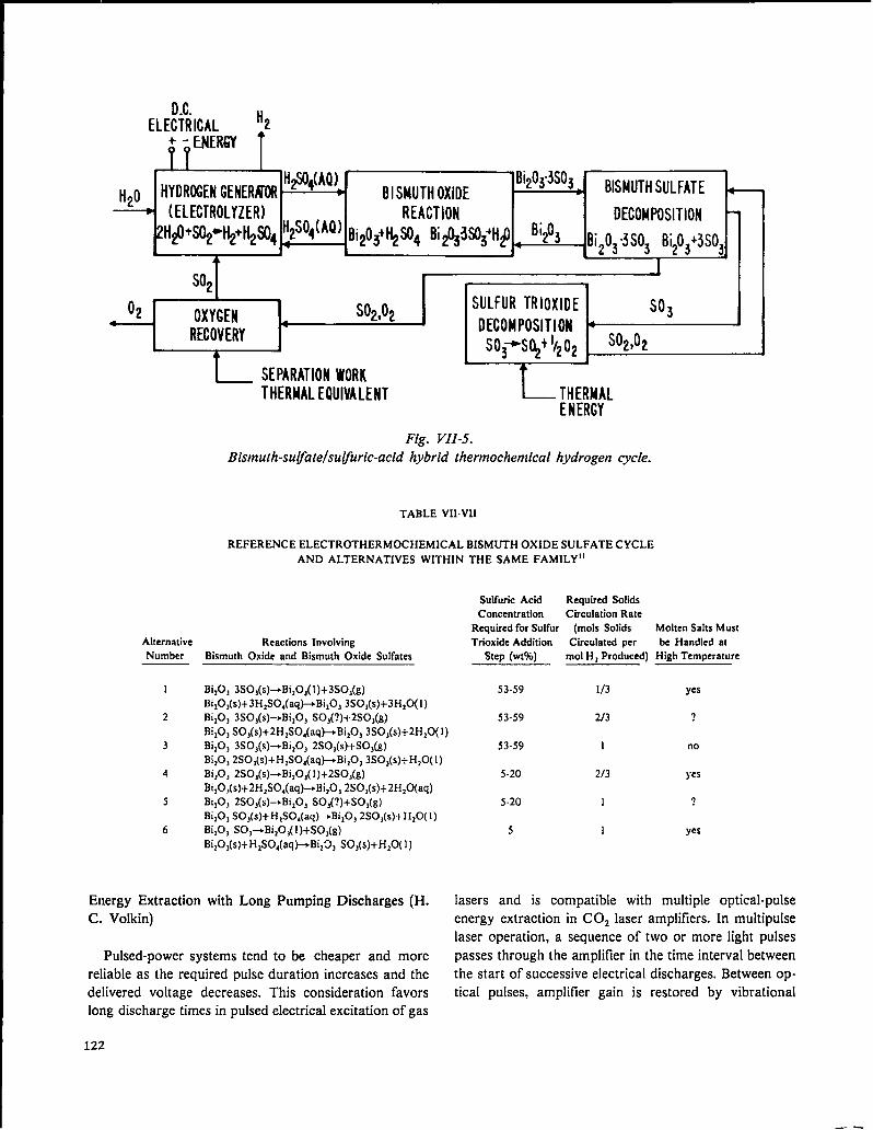
ELE&’iRICAL
H2S04(AQ)HYDROGENGENERJIOR BISMUTHSULFATE
(ELECTROLYZER) REACTION DECOMPOSITION2H#)+sq+H*+tL#14 Bi203+t$S04Bi&3SO<H#) ‘i203.Bi203“3S03Bi203+3S03
+—~
1
H20
L SEPARATIONWORKTHERMALEQUIVALENT ~MAL
ENERGY
Fig. VII-5.Bismuth-su~ate/su @ric-acid hybrid thermochemical hydrogen cycle.
TABLE VII-VII
REFERENCE ELECTROTHERMOCHEMICAL BISMUTH OXIDE SULFATE CYCLE
AND ALTERNATIVES WITHIN THE SAME FAMILY”
AlternativeNumber
1
2
3
4
5
6
Reactions InvolvingBismuth Oxide and Bismuth Oxide Sulfates
BizO, 3SOJs)~Bi,0Jl)+ 3S0,(g)
Bi10,(s)+3H2S04( aq~Bi,0, 3S0,(S)+3H,0(1)Bi,O, 3S0,(s)~Bi,0, S0,(?)+2S0,(g)
Bi,O, S0,(s)+2H,S04(aqPBi,0, 3S0,(S)+2H,0(1)BiZO, 3S0,(s)~Bi,0J 2S0,(s)+S03(g)Bi,O, 2S0,(s)+H,S0,(aq~ Bi,0, 3S0,(S)+H,0( 1)
Bi,O, 2S0,(s)aBi,0,( 1)+2S0,(g)Bi,0J(s)+2H1S04(aq~ Bi,0, 2S0,(s)+2H,0(aq)BilOj 2S0,(s)4Bi,0, SO,(?) +SOJg)Bi,O, SO,(s) +H,SO,(aq~Bi,O, 2S03(S)+H20( 1)Bi,O, S0,~Bi20,( l)+ SO,(g)
Sulfuric Acid Required SolidsConcentration Circulation Rate
Rqrsired for SuIfur (moIs Solids Molten Saks Must
Trioxide Addition Circulated per be Handled at
Step (wt%) mol H ~Produced) High Temperature
53-59 113 yes
53-59 2J3 ?
53-59 1 no
5-20 2/3 yes
5-20 1 ?
5 1 yesBi,OJs)+HISO,(aq~ Bi,~, S03(S)+H,0( 1)
Energy Extraction with Long Pumping Discharges (H. lasers and is compatible with multiple optical-pulse
C. Volkin) energy extraction in COZ laser amplifiers. In multipulse
laser operation, a sequence of two or more light pulses
Pulsed-power systems tend to be cheaper and more passes through the amplifier in the time interval between
reliable as the required pulse duration increases and the the start of successive electrical discharges. Between op-
delivered voltage decreases. This consideration favors tical pulses, amplifier gain is restored by vibrational
long discharge times in pulsed electrical excitation of gas
122
—.
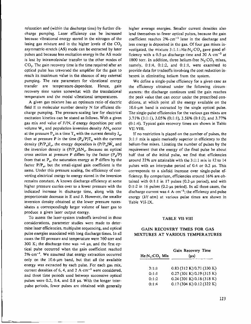
relaxation and (within the discharge time) by further dis-
charge pumping. Laser eftlciency can be increased
because vibrational energy stored in the nitrogen of the
Iasing gas mixture and in the higher levels of the COZ
asymmetric-stretch (AS) mode can be extracted by later
pulses and because less excitation energy in the AS mode
is lost by intramolecular transfer to the other modes of
COZ. The gain recovery time is the time required after an
optical pulse has traversed the amplifier for the gain to
reach its maximum value in the absence of any external
pumping. The rate parameters for vibrational energy
transfer are temperature-dependent. Hence, gain
recovery time varies somewhat with the translational
temperature and the modal vibrational temperatures.
A given gas mixture has an optimum ratio of electric
field E to molecular number density N for eflicient dis-
charge pumping. The pressure-scaling law for electrical
excitation kinetics can be stated as follows. With a given
gas mix and value of E/N, if energy deposition per unit
volume WO and population inversion density ANO occur
at the pressure POin a time TOwith the current density JO,
then at pressure P in the time (P#P)TO with the current
density (P/PO)JO, the energy deposition is (P/PO)WO and
the inversion density is (P/PO)ANO. Because an optical
cross section at pressure P differs by the factor (P~P)
from that at PO, the saturation energy at P differs by the
factor P/PO, but the small-signal gain coefficient is the
same. Under this pressure scaling, the efficiency of con-
verting electrical energy to energy stored in the inversion
remains constant. A known discharge efllciency at some
higher pressure carries over to a lower pressure with the
indicated increase in discharge time, along with the
proportionate decrease in E and J. However, the smaller
inversion density obtained at the lower pressure neces-
sitates a correspondingly larger volume of laser gas to
produce a given laser output energy.
To assess the laser-system tradeoffs involved in these
considerations, parameter studies were made to deter-
mine laser efficiencies, multipulse sequencing, and optical
pulse energies associated with long discharge times. In all
cases the fill pressure and temperature were 760 torr and
300 K; the discharge time was -4 vs, and the first op-
tical pulse occurred when the gain coefficient reached
2V0cm-1. We assumed that energy extraction occurred
only on the 10.6-~m band, but that all the available
energy was extracted by each pulse. For each gas mix,
current densities of 6, 4, and 2 A cm-2 were considered,
and three time periods used between successive optical
pulses were 0.2, 0.4, and 0.8 US. With the longer inter-
pulse periods, fewer pulses are obtained with generally
higher average energies. Smaller current densities also
lend themselves to fewer optical pulses, because the gain
coefficient reaches 20/0.cm ‘1 later in the discharge and
less energy is deposited in the gas. Of four gas mixes in-
vestigated, the mixture 3:1:1 ::He: Nz:COz gave good ef-
ficiency with a 0.5-~s discharge time and 20 A.cm-2 at
1800 torr. In addition, three helium-free NZ:C02 mixes,
namely, 0:1:4, 0:1:2, and 0:1:1, were examined to
provide data for tradeoffs involving the cost reduction in-
herent in eliminating helium from the system.
We define a single-pulse efficiency for a given case as
the efficiency obtained under the following circum-
stances: the discharge continues until the gain reaches
the peak value that can occur under the prescribed con-
ditions, at which point all the energy available on the
10.6-~m band is extracted by the single optical pulse.
The single-pulse eftlciencies for the various gas mixes are
3.71~0 (3:1:1), 3.0570 (0:1:1), 3.58’% (0:1:2), and 3.77?40(0:1 :4). Typical gain recovery times are shown in Table
VII-VIII.
If no restriction is placed on the number of pulses, the
3: I: 1 mix is again markedly superior in efficiency to the
helium-free mixes. Limiting the number of pulses by the
requirement that the energy of the final pulse be about
half that of the initial pulse, we find that efficiencies
around 22% are attainable with the 3:1:1 mix in 12 to 14
pulses with an interpulse period of 0.4 or 0.2 M. This
corresponds to a sixfold increase over single-pulse ef-
ficiency. By comparison, efficiencies around 16?40are ob-
tained with 0:1:1 in 17 pulses (0.2-ws period), and with
0:1:2 in 16 pulses (0.2-vs period). In all these cases, the
discharge current was 4 A. cm–2; the efficiency and pulse
energy (J/f. atm) at various pulse times are shown in
Table VII-IX.
TABLE VII-VIII
GAIN RECOVERY TIMES FOR GAS
MIXTURES AT VARIOUS TEMPERATURES
Gain Recovery Tiie
He: N2:C02 Mix (~s)
3:1:1 0.83 (312 K) 0.71 (330 K)
0:1:1 0.27(301 K) O.19(315 K)
0:1:2 0.24(301 K) O.18(318 K)
0:1:4 0.17 (304 K) 0.12 (322 K)
123
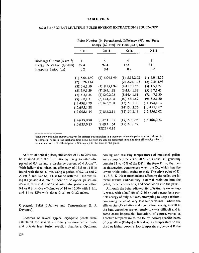
TABLE VII-IX
SOME EFFICIENT MULTIPLE-PULSE ENERGY EXTRACTION SEQUENCES’
Pulse Number (in Parentheses), Efllciency (%), and Pulse
Energy (J/t. atm) for He: Nz:COz Mix
3:1:1 3:1:1 0:1:1 0:1:2
Discharge Current (A cm-z) 4
Energy Deposition (J/f-atm) 92.4
Interpulse Period (us) 0.2
(1) 5.04,1.99
(2) 8.26,1.64
(3)10.6,1.50
(5)13.9,1.39
(7)16.2,1.34
(9)17.8,1.31
(11)190,1.29
(12)195,1.28
(13)208,1.14
(14)219,0.98
(15)229,0.83
4
92.4
0.4
(1) 5.04,1.99
(2) 8.15,1.94
(3)10.4,1.98
(4)1 2.0,2.02
(5)13.4,2.06
(6)14.5,2.08
(7)15.4,2.11
(8)17.4,1.85
(9)19.1,1.54(12)224,0.83
4
162
0.2
(1) 5.12,2.08
(2) 8.24,1.93
(4)11.7,1.76
(6)13.4,1.62
(8)14.4,1.5 1
(10)148,1.42
(12)15.1,1.33
(14)15.1,1.26
(16)15.1,1.18
(17)15.7,0.95
(18)16.1,0.72
4
134
0.2
(1) 6.04,2.27
(2) 9.45,1.93
(3)11.5,1.72
(5)13.7,1.45
(7)14.7,1.30
(9)15.2,1.20
(11)15 A,I.13
(13)155,1.07
(15)15 A,1.02
(16)160,0.73
“Efficiency and pulse energy are given for selected optical pulses in a sequence, where the pulse number is shown in
parentheses. Pulses in the discharge time occur between the double horizontal lines, and their efficiencies refer tothe cumulative electrical-to-optical efficiency up to the time of the pulse.
At 9 or 10 optical pulses, efllciencies of 19 to 20’%0can
be attained with the 3:1:1 mix by using an interpulse
period of 0.4 us and a discharge current of 4 A.cm-2.
With helium-free mixes, an efilciency of 15.5 to 16% is
found with the 0:1:1 mix using a period of 0.2 us and 2
A.cm-2, and 13.5 to 14’%0 is found with the 0:1:2 mix US-
ing 0.4 us and 4 A.cm–2. If four or five optical pulses are
desired, then 2 A. cm-z and interpulse periods of either
0.4 or 0.8 us give efficiencies of 14 to 16.5V0 with 3:1:1,
and 11 to 12’3’0with either 0:1:1 or 0:1:2 mixes.
Cryogenic Pellet Lifetimes and Temperatures (J. J.
Devaney)
Lifetimes of several typical cryogenic pellets were
calculated for several customary environments inside
and outside laser fusion reaction chambers. Optimum
124.
cooling and resulting temperatures of multishell pellets
were computed. Pellets of 50:50 at. Yosolid D:T generally
contain 31 to 46V0 of the DT in the form Dz, so that pel-
let destruction commences when the D2, which has the
lowest triple point, begins to melt. The triple point of Dz
is 18.71 K. Heat mechanisms affecting the pellet are in-
ternal tritium radioactivity, external radiation into the
pellet, forced convection, and conduction into the pellet.
Although the beta radioactivity of tritium is exceeding-
ly weak, with a half-life of 12.26 yr and a mean beta par-
ticle energy of only 5.7 keV, attempting to keep a tritium-
containing pellet at very low temperatures—where the
efficiencies of radiative and conductive cooling as well as
the heat capacities are extremely low—is difficult and in
some cases impossible. Radiation, of course, varies as
absolute temperature to the fourth power; specific heats
of crystalline (Debye) solids drop as temperature to the
third or higher power at low temperatures; below 4 K the
—
conduction-electron contributions to the specific heat are
significant and are proportional to temperature; the
specific heats of many plastics are roughly proportional
to temperature over a wide low-temperature range; and
last, low-temperature thermal conductivities all show
decreases with decreasing temperature, very roughly
directly proportional to the temperature. In fact,
radiation-cooling has dropped to such a low level around
4 to 20 K that typical pellet designs containing ap-
preciable amounts of solid DT within a vacuum cannel
exist at all. Steady-state DT temperatures calculated for
such pellets at absolute zero in vacuum range from 88 to
114 K, well above the Dz triple point.
Such pellets, therefore, need ‘direct cooling of inner
DT-containing structures and have lifetimes away from
such cooling of typically 26 to 80 s if initially at 10 K,
and of 30 to 95 s if initially at 4.2 K. However, in mul-
tishell pellets, even a low-density interstitial gas such as
hydrogen or helium is very effective in cooling inner shell
structures. Ironically, too low a coolant temperature will
condense too much of the conductive gas, and so allow
inner DT structures to melt. For example, one of our pel-
let designs will survive only if the outer shell structure is
kept between 7.9 and 18.2 K. In this design the minimum
inner DT temperature of 9.4 K is achieved for an outer
cooling bath of 9.0 K. All other coolant temperatures
lead to a higher inner DT temperature.
The high external temperatures of a laser fusion reac-
tor cavity Iirther restrict the lifetime of a pellet.
However, the pellet designer has considerable control
over the melting of restrictive parts, i.e., solid DT, by
rather modest pellet design changes. For example, by
aluminizing exposed plastic parts, he can reduce the ac-
quisition of radiative energy, or by using low-
conductivity materials, he can restrict the heat flow;
these changes can account for extensive lifetime changes.
We examined the survival of laser fusion pellets in two
extreme reaction-chamber atmospheres, marking the up-
per and lower bounds of expected chamber lifetimes for
the pellets investigated, namely, 1017 atom/cm3 of argon
at 773 K and a vacuum at the same temperature. A high
pellet injection speed of 13 700 cm/s was assumed. We
found that Rayleigh-Benard instabilities do not develop
and that all relevant flows are laminar. Our worst case, a
pellet moving at 13700 cm/s in 1017 atoms/cm3 at 773
K with sensitive areas exposed and with an initial
temperature of 10 K, will last 0.048 s. A protected pellet
(aluminized, baffled-best case for this general design)
will live 64 s in a 773 K vacuum if initially at 10 K.
Pellet Injection and Tracking (J. J. Devaney)
A preliminary investigation of potential pellet and
laser beam space-time interaction systems for inertial
confinement fusion reactors, with emphasis on C02
laser-driven reactors, was completed under contract to
United Technologies Research Center.zo
We examined the synchronization requirements;
velocity requirements; accelerators, including
gravitational, mechanical, pneumatic, and electrical;
tracking, including accuracy required, degrees of
freedom, measurement resolution, reference frame
stability, and some merits of tracking both within and
without the chamber; guidance, including trajectory cor-
rection required, types of guide tubes, and electrostatic
guidance; beam pointing, including active-optics techni-
ques and capabilities and nonlinear phase conjugation;
and pellet velocity tradeoffs. Three systems that may
have merit were identified: (1) adaptive laser optics
operated in a predictive mode, with pellet tracking inside
and outside the reactor; (2) feedback-controlled elec-
trostatic guidance of the pellet, with high-precision track-
ing and guidance external to the reactor; and (3) a com-
bined adaptive optics-electrical guidance system, with
relaxed operating parameters for both subsystems. The
primary critical issue was identified as the ability to
make the position and velocity tracking measurements
with the required speed and accuracy. Other critical
issues include reference frame motion, injector accuracy,
and injector reliability.Based on the information developed in this study,
system recommendations shown in Table VII-X are
made for 100-m/s injection velocities. Such high
velocities are needed if high repetition rates are desired.
The preferred system uses adaptive optics to point and
focus the laser beams on the pellet. Due to insufficient
slew rate, the adaptive optics must operate in the predic-
tive mode, whereby the pellet trajectory at the focus is
predicted based on precise tracking data, and the laser
beams are aimed and focused before the arrival of the
pellet at the focal region. Errors between tracking and
adaptive-optics reference frames (due to, e.g., noise and
vibration) are assumed to be less than errors in trajectory
measurement. In practice, this implies active tracking
between reference frames and precise autoalignment of
all beams. Guidance in this system is provided only by
the rough constraint of inherent angular scatter of the
pellet accelerator imposed by a mechanical guide tube.
The accelerator is a pneumatic gas gun, and pellets are
125

TABLE VII-X
PELLET/LASER BEAM SPACE/TIME SYSTEM RECOMMENDATIONS
(Pellet Velocity, 100 m/s)
Beam
Pointing
Mode
Guidance
Tracking
Propulsion
Recommended Not Recommended
Phase
Active None Active Active conjug.
Predictive Predictive Predictive Active Passive
Guide Electro- Electro- Guidetube static static None tube
Inside & Inside & Inside &outside Outside outside outside Inside
Pneumatic Pneumatic
tracked both outside and inside the reactor for adaptive
optics control and synchronization of laser fire. Some
autoalignment and initial trajectory measurement re-
quirements are relaxed if final tracking can be performed
inside the reactor through each beam line using shared
apertures.
An alternative system with fixed optics relies on
electrostatic guidance of electrically charged pellets to
place pellets on the correct trajectory to pass through the
focal region. The tracking requirements on this system
are very severe and must be sufllciently precise to func-
tion solely on measurements outside the reactor.
A hybrid system that combines adaptive optics and
electrostatic guidance is also possible. This approach
relaxes performance requirements on both systems, but
at the cost of increased system complexity.
The above system recommendations are based on the
assumption that the injection velocity is 100 m/s. If the
reactor could be designed so that the injection velocity
were significantly reduced, then the above conclusions
would be altered. Such a design would change the means
of(1) propulsion, (2) tracking, and (3) pellet irradiation.
If the injection velocity were 25 m/s or less,
gravitational acceleration is a reasonable and preferred
means of target propulsion. (A velocity of 25 mfs re-
quires a drop tower of only 32 m in height.) Pellet motion
during a pulse round trip through the laser system (which
takes 2 I.IS)would be 50 ~m or less so that phase con-
jugation—passive focusing by nonlinear optics—is not
ruled out on the basis of pellet motion.
Pneumatic Pneumatic Pneumatic
If the injection velocity were =10 m/s or less, the re-
quired mirror slew rates are low enough so that actively
tracking adaptive optics could be used for pellet
trajectory-beam direction relative angles of less than
100. This case would apply to each beam in the polar il-
lumination case when the pellet is injected along the
beam-direction axis. Autoalignment system requirements
would again be eased by shared aperture tracking on all
beams, but in addition, low pellet velocity would
eliminate the need to predict pellet position at the focus
and should produce more accurate pellet irradiation.
Pellet tracking and trajectory measurement require-
ments are greatly eased by lower velocities. The time in-
terval during which position determination must be made
increases and the accuracy with which the velocity must
be measured may decrease. This last factor increases the
feasibility of a system that does not include tracking in-
side the reactor for synchronization. At lower velocity,
the voltage or the length of the guide-plate region re-
quired to electrostatically correct trajectory errors, is
also less.
In summary, many benefits in reducing pellet injection
system complexity and cost would be derived from lower
pellet injection velocities. Furthermore, the nature oft he
preferred system is a strong function of pellet velocity,
Finally, this preliminary study should be interpreted as
a first exploration of conventional state-of-the-art techni-
ques, and not be considered a definitive review of all pos-
sibilities including highly innovative techniques.
126

REFERENCES
1. L. A. Booth, Comp., “Central Station Power
Generation by Laser-Driven Fusion;’ Los Alamos
Scientific Laboratory report LA-4858-MS, Vol. 1
(February 1972).
2. J. J. Devaney, “Magnetically Protected First Wall
for a Laser-Induced Thermonuclear Reaction,” Los
Alamos Scientific Laboratory report LA-5699-MS
(August 1974).
3. “Inertial Fusion Program, July 1—December 31,
1978,” Los Alamos Scientific Laboratory report
LA-7587-PR (May 1980).
4. R. W. Corm et al., “Solase, A Conceptual Laser Fu-
sion Reactor Design,” University of Wisconsin
report U WFDM-220 (December 1977).
5. 1. 0. Bohachevsky and J. F. Hafer, “Sputtering
Erosion of Fusion Reactor Cavity Walls,” Los
Alamos Scientific Laboratory report LA-6633-MS
(December 1976).
6. I. O. Bohachevsky and J. F. Hafer, “Dependence of
Sputtering Erosion on Fuel Pellet Characteristics,”
Los Alamos Scientific Laboratory report LA-699 1-
MS (November 1977).
7. “Laser Fusion Program at LASL, January 1—June
301977,” Los Alamos Scientific Laboratory report
LA-6982-PR (April 1978), p. 135.
8. S. Chow and L O. Bohachevsky, “MHD Decelera-
tion of Fusion Reaction Products,” Los Alamos
Scientific Laboratory report in preparation.
9. J. C. Goldstein, I. O. Bohachevsky, and D. O.
Dickman, “Ion Motion in Laser Fusion Reactor
Studies,” Paper 9P7, Bull. Am. Phys. Sot., Series 11
21 (October 1976).
10. G. A. DeMastry, “Corrosion Studies of Tungsten,
Molybdenum, and Rhenium, in Lithium,” Nucl. Ap-
pl. 3, 127 (1967).
11. Y. Amagi, Y. Nishimura, and S. Gomi, “Hollow
Carbon Microsphere from Pitch Material and their
Applications,” Materials ‘71, 16th National Symp.
and Exhibit, Sot. of Aerospace Material and
Process Engineers, Anaheim, California (April 21-
23, 1971), p. 315.
12. G. V. Fitzpatrick and E. J. Britt, “Thermionic
Central Station Power—The THX Approach—-
Topical Report,” Rasor Associates, Inc., report
NSR 2-6 (February 1977).
13. T. G. Frank, “A Thorium-Uranium Cycle ICF
Hybrid Concept,” Proc. 3rd Topical Meeting on the
Technology of Controlled Nuclear Fusion, Santa
Fe, New Mexico (May 1978).
14. L. A. Booth and T. G. Frank, “Commercial Ap-
plications of Inertial Confhement Fusion,” Los
Alamos Scientific Laboratory report LA-6838-MS
(May 1977).
15. “Guide for Economic Evaluation of Nuclear Power
Plant Designs,” NUS Corporation report NUS-S31
(January 1965).
16. United Engineers and Constructors, Inc., “1000-
MW(e) Central Station Power Plants—Investment
Cost Study,” WASH- 1230, Vols. I-IV (June 1972).
17. L. A. Booth, M. G. Bowman, G. E. Cort, K, E. Cox,
D. J. Dudziak, R. A. Krakowski, J. H. Pendergrass,
and A. S. Tar, “Production of Electrother-
mochemical Hydrogen using a Fusion Source of
High-Temperature Process Heat/’ Proc. 3rd ANS
Topical Meeting on the Tech. of Controlled Nuclear
Fusion (to be published).
18. A. Tai and R. Krakowski, “Generalized Energy—-
Balance and Economic Considerations for Ther-
mochemical Hydrogen Production from Fusion
Reactor Blankets,” Trans. Am. Nucl. Sot. Winter
Meeting, Washington, DC (1978).
19. K. E. COX, “Thermochemical Processes for
Hydrogen Production,” Los Alamos Scientific
Laboratory report LA-6970-PR (October 1977).
20. R. G. Tomlinson et al., “Pellet and Laser Beam
Space-Time Interaction System Study,” UTRC
R78-9543 73-1, Los Alamos Scientific Laboratory
Contract LP8-2822E (November 1978).
127

VIII. RESOURCES, FACILITIES, AND OPERATIONAL SAFETY
The design and construction of HEGLF facilities continued. Safety policies and
procedures continued to be successful in minimizing the hazards of operating high-
energy lasers.
MANPOWER DISTRIBUTION
The distribution of employees assigned to the various
categories of the DOE-supported Laser Fusion Research
Program is shown below.
APPROXIMATE STAFFING
LEVEL OF LASER PROGRAM
December 31, 1978
Tasks
COZ Laser Development
COZ Laser Experiments
Target Design
Target Fabrication
Diagnostics Development
Systems and Applications Studies
Advanced Technology
Weapons Application
TOTAL
Direct
Employees
77
115
27
41
40
8
3
9
3;
High-Energy Gas Laser Facility (HEGLF)
Construction Package I, including the laser building,
the mechanical building, the office building, and a
warehouse is 40% complete, with a scheduled comple-
tion date of September 1979.
Construction Package H, including the target building,
the power-transmission system, and miscellaneous con-
128
struction is 42’% complete with a scheduled completion
date of August 1979.
In the interest of continuity, we have presented details
in HEGLF Design and Construction in Sec. II.
New Laboratories
The contract for the High-Voltage and Optical-
Evaluation Laboratories was awarded in January 1978;
construction is essentially complete, with a scheduled oc-
cupation date of January 22, 1979.
OPERATIONAL SAFETY
General
Laser Fusion Research Program activities have never
caused biological damage to any employee from laser
radiation. The excellent lost-time injury rate was also
maintained, despite increased activities and additional
staff.
Laser Protective Eyewear Movie
A 16-mm color movie, “Lasers and Your Eyes,” wasproduced for indoctrination of new employees and for
use by industry and Academe to demonstrate the poten-
tial ocular hazards of lasers and to share information
about available protective eyewear developed in the
Laser Fusion Program for lightweight corrective spec-
tacles from a series of colored filter glass.
IX. PATENTS, PUBLICATIONS, AND PRESENTATIONS
PATENTS
Serial numbers, filing dates, patent numbers, and issue
dates may not be shown for several months after they are
assigned. Therefore, for any given period, cases may be
missing from these listings if patent activity occurred late
in the reporting period.
S. N. 928,027—
S. N. !M2,227—
S. N. 945,376—
S. N. 951,203—
S. N. 951,543—
S. N. 960,410—
“Laser Target Fabrication, Struc-
ture and Method for Its
Fabrication,” E. H. Farnum and R.
J. Fries, filed July 25, 1978.
“Enhancement of Laser Pulse
Contrast Ratios Via Transient
Response of Narrow Band Reso-
nant Interferometers,” R. A. Fisher
and B. J. Feldman, filed September
14, 1978.
“Fiber Optic Solid State Switch,”
M. E. Thuot, filed September 25,
1978.
“Vacuum Aperture Isolator for
Retroreflection from Laser-
Irradiated Targets,” R. F. Benjamin
and K. B. Mitchell, tiled October 13,
1978.
“High Power Laser Amplifier;’ W.
T. Leland and T. F. Stratton, filed
October 13, 1978.
“Beam Heated Linear Theta-Pinch
Device for Producing Hot
Plasmas,” 1.0. Bohachevsky, filed
November 13, 1978.
PUBLICATIONS
E. R. Grilly, “Development of Cryogenic Targets for
Laser Fusion,” TIC (1 977), 13 pp. MN, and Adv.
Cryog. Eng. 23 (1978), pp. 676-81.
A. T. Lowe and R. J. Fries, “Plasma Polymerized P-
Xylene as a Laser Fusion Target,” Sur. Sci. 76, pp. 252-
56.
K. B. Mitchell and R. P. Godwin, “Energy-Transport
Experiments in 10 Micrometer Laser-Produced
Plasmas,” J. App. Phys. 49, pp. 3851-4.
K. B. Reipe and M. Kircher, “Design of the Energy
Storage System for the High Energy Gas Laser Facility
at LASL,” Engineering Problems of Fusion Research
7th Symp. Proc. 2, M. S. Lubell, Ed., Knoxville, Tennes-
see (1977), pp. 1053-5. ,
B. E. Newnam and D. H. Gill, “Damage Resistance of
Ar-Coated Germaniuni Surfaces for Nanosecond
Carbon Dioxide Laser Pulses:’ TIC (1977), 19 pp.
B. E. Newnam, “Damage Resistance of Coated optics
for Pulsed Carbon Dioxide Lasers:’ SPIE, Proceedings
of Optical Coatings—Applications and Utilization II,
TIC (1978), 18 pp. ;
S. J. Gitomer, “Laser Induced Fusion, IEEE Minicourse,
2nd, Proc., G. H. Miley, Ed., Troy, New York (1977),
pp. 10-20.
E. E. Bergmann, 1. J. Bigio, B. J. Feldman, and R. A.
Fisher, “High-Efficiency Pulsed 10.6 Micrometer
Phase—Conjugate Reflection Via Degenerate Four-
Wave Mixing,” Opt. Lett. 3 (1978), pp. 82-4.
F. D. Wells and D. Remington, “Mirror Position Display
Equipment for the Target Chamber Mirror Mounts of
the 8-Beam Laser Fusion Research Facility,” Cube
Symp. Abst. J. J. Ruminer, Comp. (1978), pp. 8?-2.
E. E. Stark, “Overview bf Laser Fusion,” Los Alamos
Scientific Laboratory Mini-Review LASL-77-24 (1 978).
M. J. Campbell, “Device for Microparticle Array
Preparation,” Rev. Sci. Instrum. 49 (1978), pp. 1488-9.
M. E. Thuot, “Fiber Optics and Microprocessors—A
Control-System Solution for the Laser-Fusion En-
vironment,” TIC (1978), 16 pp.
J. E. Sollid, S. J. Thomas, E. Foley, and C. R. Phipps,
“Threshold of Detection for Various Materials at 10.6
Micrometers,” Appl. Opt. 17 (1978), pp. 2670-1.
J. J. Devaney, “Injection of Laser Fusion Pellets. Part 1.
Accuracy Required, Acceleration, and Residual Gas
Deflections,” Los Alamos Scientific Laboratory report
LA-7477-MS (1978). ‘
129

J. E. Sollid, “Diffraction Measurement for LASL’S An-
tares Laser System:’ LAMAlamos Scientific Laboratory
report LA-7443-MS (1978).
C. W. Crantill, and R. More, “IONOS. A Fast, Analytic,
Ion Equation-of-State Routine,” Los Alamos Scientific
Laboratory report LA-73 13-MS (1978).
R. L. Whitman, R. H. Day, R. Kruger, and D. M.
Stupin, “Analysis of Laser Fusion Targets Using
Monochromatic X-Ray Microradiographs,” Los Alamos
Scientific Laboratory report LA-7534-MS (1978).
M. A. Stroscio, D. B. Henderson, and A. G. Petschek,
“Numerical Computation of the Density Profile
Produced by 10.6 Micrometer Irradiation of a Silicon
Dioxide Microballoon,” Nucl. Fusion 18 (1978). pp.
1425-30.
R. K. Ahrenkiel, “Properties of Cobalt Chromium
Sulfide Applicable to Faraday Rotators for Carbon
Dioxide Laser Systems,” IEEE Trans. Magn. 14(1978),
pp. 454-6.
E. E. Stark, “Lasers and Power Systems for Inertial
Confinement Fusion Reactors,” TIC (1978), 24 pp.
E. E. Stark, “Carbon Dioxide-Laser Fusion,” Proc. 13th
Intersociety Energy Conversion Engineering Conf.,
August 20-25, 1978, pp. 1362-1365.
A. J. Scannapieco and E. W. Cranfill, “Derivation of the
Physical Equations Solved in the Inertial Confinement
Stability Code DOC,” Los Alamos Scientific Laboratory
report LA-7214-MS (1978).
W. T. Leland, “Design Engineering of Large High Pres-
sure Gas Laser Amplifiers,” TIC (1978).
W. T. Leland, “Advances in Laser Technology
(Emphasizing Gaseous Lasers),” (Proc. SPIE Seminar,
D. Finkleman, Ed., Washington, DC, 1978), pp. 38-45.
R, K. Ahrenkiel, J. F. Figueira, C. R. Phipps, and D.
Dunlavy, ‘&New Saturable Absorber for the Carbon
Dioxide Laser Using Doped KC1,” Appl. Phys. Lett. 33
(1978), pp. 705-7.
J. L. Lyman, R. G. Anderson, R. A. Fisher, and B. J.
Feldman, “Absorption of Pulsed COZ Laser Radiation of
SF, at 140 K,” Optics Lett. 3238 (1978).
J. E. Sollid, C. R. Phipps, Jr., and E. J. McLellan, “A
Lensless Method of Measuring Gaussian Laser Beam
Divergence,” Appl. Opt. 173527 ( 1978).
PRESENTATIONS
The following presentations were made at the Annual
Meeting of the Optical Society of America, San Fran-
cisco, California, October 30—November 3, 1978.
R. A. Fisher, E. E. Bergmann, B. J. Feldman, and L J.
Bigio, “Phase Conjugate Reflections at 10.6 pm via
Interactivity Degenerate 4 Wave Mixing in Germanium.”
S. C. Stotlar, E. J. McLellan, and A. J. Gibbs, “Ultra-
Fast Pyroelectric Detectors for C02 Laser
Measurements.”
R. A. Fisher and B. J. Feldman, “Phase Conjugation in
Inverted COv”
J. E. Sollid, “A Lensless Measurement of Gaussian Laser
Beam Divergence.”
W. C. Sweatt and V. L. Zeigner, “Antares Target
System Optical Design.”
D. M. Stupin, M. A. Winkler, M. J. Campbell, and R.
Llepins, “Radiographic Selection of Laser Fusion
Targets: Hollow Metal Shells and Plastic Coatings.”
The following presentations were made at the 1978
International Laser Conference, Orlando, Florida,
December 11-15, 1978.
R. K. Ahrenkiel, D. Dunlavy, J. F. Figueira, and C. R.
Phipps, Jr., “A New 10.6 ~m Saturable Absorber: KC1
Doped with KReO@”
S. J. Czuchlewski, E. J. McLellan, J. F. Figueira, E.
Foley, C. E. Knapp, and J. A. Webb, “A High-Power
(-10 GW) Short-Pulse (<1 ns) COZ TEA Amplifier.”
130

I. J. Bigio, B. J. Feldman, R. A. Fisher, and E. E.
Bergmann, “High Efficiency Phase-Conjugate Reflection
in Germanium and in Inverted C02.”
E. J. McLellan, “A Reinfection COZ Oscillator.”
The following presentations were made at the Electro-
Optics Laser ’78 Conference, Boston, Massachusetts,
September 19-21, 1978.
E. J. McLellan and S. C. Stotlar, “Sub-One-hundred-ps
Pyroelectric Detector Research and Evaluation Program
at LASL.”
R. A. Fisher, E. E. Bergmann, b. J. Feldman, and I. J.
Bigio, “Phase-Conjugate Reflection at 10.6 ~m via
Degenerate 4-Wave Mixing in Germanium.”
K. C. Jones, J. L. Munroe, W. H. Reichelt, and J. E. Sol-
lid, “Antares COZ Laser System, Optics and Com-
ponents.”
The following presentations were made at the Twen-
tieth Annual Meeting of the Division of Plasma Physics
of the American Physical Society, Colorado Springs,
Colorado, October 30—November 3, 1978.
C. W. Cranfill and R. Moore (H-Division, LLL, Califor-
nia), “IONEOS: A Fast, Analytic, Ion-Equation of State
Routine.”
S. J. Gitomer and R. J. Mason, “A New COZ Laser
Target with Burnthrough Shields,”
A. J. Scannapieco and H. Brysk, “Symmetry of Energy
Deposition by a Multibeam Laser System.”
S. J. Gitomer, “Spectral Analysis Techniques Applied to
Subnanosecond Laser.”
R. A. Kopp, “High Compression Ablative Targets for
the Helios Laser System.”
R. J. Mason, “Laser Generated Hot Electron Transport
in Self-Consistent E and B Fields.”
A. J. Scannapieco, “Illumination and Energy Deposition
in a Multi-Beam Laser-Fusion System.”
A. J. Scannapieco and K. A. Taggart, “Stability of Laser
Fusion Targets.”
W. S. Varnum and E. L. Lindman, “Antares Design
Concepts II.”
The following presentations were made at the ANS
1978 Winter Meeting, Washington, DC, November 12-
17. 1978.
J. J. Devaney and L. A. Booth, “Laser-Fusion Pellet In-
jection Accuracies, Accelerations and Deflections.”
I. O. Bohachevsky, D. O. Dickman, and J. C. Goldstein,
“A New Plasma Model for the ICF Magnetic Wall
Reactor Cavity Concept.”
J. H. Pendergrass and C. E. Cort, “Lithium Boiler High-
Temperature Fusion Reactor Blanket Concept.”
In addition, the following presentations were made at
various institutions.
R. K. Ahrenkiel, “A New Saturable Absorber for the
COZ Laser Using Doped KC1,” Seminar, University of
Rochester, August 21-22, 1978.
J. H. Birely, J. L. Lyman, G. Quigley, R. A. Fisher, and
B. J. Feldman, “Multiple Photon Absorption
Measurements,” National Conference on Nonlinear Op-
tics and Lasers, Lenigrad, USSR, July 1978.
R. A. Fisher, B. J. Feldman, I. J. Bigio, and E. E.
Bergmann, “Infrared Wavefront Reversal in Ger-
manium,” National Conference on Nonlinear Optics and
Lasers, Leningrad, USSR, July 1978.
B. J, Feldman, R. A. Fisher, E. E. Bergmann, and I. J.
Bigio, “Infrared Phase Conjugation,” Massachusetts In-
stitute of Technology, July 1978.
R. A. Fisher, B. J. Feldman, “Infrared Phase Conjuga-
tion,” Seminar, Sandia Laboratories, Albuquerque, July
1978.
R. A. Fisher and B. J. Feldman, “ 10-yin Photoplasma
Formation in Germanium,” Seminar, Sandia
Laboratories, Albuquerque, July 1978.
R. A. Fisher, B. J. Feldman, I. J. Bigio, and E. E.
Bergmann, “Infrared Phase Conjugation Via 4-Wave
Mixing in Germanium,” Seminar, Physics Department,
University of California, Berkeley, November 1, 1978.
131

B. J. Feldman, R. A. Fisher, I. J. Bigio, and E. E.
Bergmann, “Infrared Phase Conjugation,” Seminar,
Lawrence Livermore Laboratory, November 3, 1978.
R. A. Fisher, B. J. Feldman, I. J. Bigio, and E. E.
Bergmann, “Phase-Conjugate Optics in the Infrared:
Seminar, Stanford University, Palo Alto, California,
November 5, 1978.
R. A. Fisher, E. E. Bergmann, B. J. Feldman, and I. O.
Bigio, “Phase Conjugation; the Wave of the Future,”
Seminar, Physics Department, Lehigh University,
Bethlehem, Pennsylvania, October 18, 1978.
B. J. Feldman, R. A. Fisher, E. E. Bergmann, and I. J.
Bigio, “Infrared Phase Conjugation,” Seminar, Stanford
Research Institute, Menlo Park, California, October 27,
1978.
R. A. Fisher, B. J. Feldman, E. E. Bergmann, and L J.
Bigio, “Infrared Phase Conjugation,” Seminar, Optical
Sciences Center, University of Arizona, October 17,
1978.
B. J. Feldman, R. A. Fisher, I. J. Bigio, and E. E.
Bergmann, “Wavefront Reversal in Nonlinear Optics,”
Seminar, Westinghouse Research Laboratories, Pitt-
sburgh, Pennsylvania, October 16, 1978.
J. P. Hong, “Experiments in Minimum Length Represen-
tation of Text,” Third Berkeley Workshop on
Distributed Data Management and Computer Networks,
Berkeley, California, August 29-31, 1978.
J. P. Hong and S. Johnson, “Minimum Length Represen-
tation of Text,” Seventeenth IEEE Computer SocietyInternational Conference (COMPCON 78),
Washington, DC, September 5-8, 1978.
R. Williamson, “A 60-Inch Annular Pitch Polisher for
LASL’S Laser Fusion Effort,” Abstract of talk given at
Optical Society of America Optical Fabrication and
Testing Workshop, Dallas, Texas, November 1-10,
1978.
T. F. Stratton, “Antares Overview,” Los Alamos
Chapter of the Laser Institute of America, Los Alamos,
New Mexico, November 14, 1978.
A. T. Lowe and C. D. Hosford, “Magnetron Sputter
Coating of Microspherical Substrates:’ National
American Vacuum Society Meeting, San Francisco,
California, November 27—December 1, 1978.
I. O. Bohachevsky, “Elements to be Considered in Plan-
ning Heavy Ion Fusion Program—A Summary,” Proc.
Heavy Ion Fusion Workshop, Argonne National
Laboratory, September 19-26, 1978,
E. E. Stark, “COz-Laser Fusion,” Thirteenth Intersociety
Energy Conversion Engineering Conf., San Diego,
California, August 20-25, 1978.
T. G. Frank and L. A. Booth, “Commercial Applications
of Thermionic Conversion Using a Fusion Reactor
Energy Source—A Preliminary Assessment,” Thirteenth
Intersociety Energy Conversion Engineering Conf., San
Diego, California, August 20-25, 1978.
A. R. Larson and C. D. Cantrell, “An Application of
Nonequilibrium Quantum Statistical Mechanics to
Homogeneous Nucleation,” 1 lth International Sym-
posium on Rarefied Gas Dynamics, Cannes, July 3-8,
1978.
C. R. Phipps and S. J. Thomas, “ 10-~m Photoplasma
Formation in Germanium,” Seminar, Sandia
Laboratories, Albuquerque, July 1978.
W. H. Reichelt, “Damage Considerations in Short Pulse
COZ Laser Systems,” 10th Annual Symposium on Op-tical Materials for High-Power Lasers, Boulder,
Colorado, September 12-14, 1978.
* U.S. GOVERN MEW PRIN71NG OFFICE. 1980-777.089/1 O
132

Domestic NTISPage Range Price price Code
001-025 s S.oo A020260S0 6.00 A03
05147s 7.00 A04076-100 8.00 A05101-125 9.00 A06126-150 10.00 A07
Printed in the United States of AmericaAvailable from
National Technical Information ServiceUS Department of Commerce
S285 Port Royal RoadSpringfield, VA 22161
Microfiche S3.S0 (AO1)
Domestic NTIS Domestic NTISPage Range Rice FYice Code Page Range Rice Rice Code
151-175 $11.00 A08 301-32s S17.00 A14176-200 12.00 A09 326-350 18.00 A15201-225 13.00 AlO 351-375 19.00 A16226-250 14.00 All 376400 20.00 A17251.275 15.00 A12 401425 21.00 A18276-300 16.00 A13 426450 22.00 A19
tAdd S1.00 for each additional 25-page increment or porkn thereof from 601 Page$up
Domestic NTISPage Range Price Price Code
451-275 S23.00 A20476-500 24.00 A21501-52S 2s .00 A22S26-SS0 26.00 A23SS1-S7S 27.00 A24S76.600 28.00 A2S601-uP t A99