FASM
125
flat assembler 1.69 Programmer’s Manual Tomasz Grysztar
Transcript of FASM

flat assembler 1.69Programmer’s Manual
Tomasz Grysztar

2

Contents
1 Introduction 71.1 Compiler overview . . . . . . . . . . . . . . . . . . . . . . . . 7
1.1.1 System requirements . . . . . . . . . . . . . . . . . . . 71.1.2 Compiler usage . . . . . . . . . . . . . . . . . . . . . . 81.1.3 Keyboard commands in editor . . . . . . . . . . . . . . 91.1.4 Editor options . . . . . . . . . . . . . . . . . . . . . . . 111.1.5 Executing compiler from command line . . . . . . . . . 121.1.6 Command line compiler messages . . . . . . . . . . . . 131.1.7 Output formats . . . . . . . . . . . . . . . . . . . . . . 14
1.2 Assembly syntax . . . . . . . . . . . . . . . . . . . . . . . . . 141.2.1 Instruction syntax . . . . . . . . . . . . . . . . . . . . 151.2.2 Data definitions . . . . . . . . . . . . . . . . . . . . . . 161.2.3 Constants and labels . . . . . . . . . . . . . . . . . . . 171.2.4 Numerical expressions . . . . . . . . . . . . . . . . . . 191.2.5 Jumps and calls . . . . . . . . . . . . . . . . . . . . . . 201.2.6 Size settings . . . . . . . . . . . . . . . . . . . . . . . . 21
2 Instruction set 232.1 The x86 architecture instructions . . . . . . . . . . . . . . . . 23
2.1.1 Data movement instructions . . . . . . . . . . . . . . . 232.1.2 Type conversion instructions . . . . . . . . . . . . . . . 252.1.3 Binary arithmetic instructions . . . . . . . . . . . . . . 262.1.4 Decimal arithmetic instructions . . . . . . . . . . . . . 282.1.5 Logical instructions . . . . . . . . . . . . . . . . . . . . 292.1.6 Control transfer instructions . . . . . . . . . . . . . . . 312.1.7 I/O instructions . . . . . . . . . . . . . . . . . . . . . . 352.1.8 Strings operations . . . . . . . . . . . . . . . . . . . . . 352.1.9 Flag control instructions . . . . . . . . . . . . . . . . . 372.1.10 Conditional operations . . . . . . . . . . . . . . . . . . 382.1.11 Miscellaneous instructions . . . . . . . . . . . . . . . . 392.1.12 System instructions . . . . . . . . . . . . . . . . . . . . 40
3

4 CONTENTS
2.1.13 FPU instructions . . . . . . . . . . . . . . . . . . . . . 422.1.14 MMX instructions . . . . . . . . . . . . . . . . . . . . 472.1.15 SSE instructions . . . . . . . . . . . . . . . . . . . . . 492.1.16 SSE2 instructions . . . . . . . . . . . . . . . . . . . . . 542.1.17 SSE3 instructions . . . . . . . . . . . . . . . . . . . . . 582.1.18 AMD 3DNow! instructions . . . . . . . . . . . . . . . . 602.1.19 The x86-64 long mode instructions . . . . . . . . . . . 612.1.20 SSE4 instructions . . . . . . . . . . . . . . . . . . . . . 642.1.21 AVX instructions . . . . . . . . . . . . . . . . . . . . . 692.1.22 Other extensions of instruction set . . . . . . . . . . . 69
2.2 Control directives . . . . . . . . . . . . . . . . . . . . . . . . . 702.2.1 Numerical constants . . . . . . . . . . . . . . . . . . . 702.2.2 Conditional assembly . . . . . . . . . . . . . . . . . . . 712.2.3 Repeating blocks of instructions . . . . . . . . . . . . . 742.2.4 Addressing spaces . . . . . . . . . . . . . . . . . . . . . 752.2.5 Other directives . . . . . . . . . . . . . . . . . . . . . . 772.2.6 Multiple passes . . . . . . . . . . . . . . . . . . . . . . 78
2.3 Preprocessor directives . . . . . . . . . . . . . . . . . . . . . . 812.3.1 Including source files . . . . . . . . . . . . . . . . . . . 812.3.2 Symbolic constants . . . . . . . . . . . . . . . . . . . . 812.3.3 Macroinstructions . . . . . . . . . . . . . . . . . . . . . 832.3.4 Structures . . . . . . . . . . . . . . . . . . . . . . . . . 912.3.5 Repeating macroinstructions . . . . . . . . . . . . . . . 922.3.6 Conditional preprocessing . . . . . . . . . . . . . . . . 942.3.7 Order of processing . . . . . . . . . . . . . . . . . . . . 96
2.4 Formatter directives . . . . . . . . . . . . . . . . . . . . . . . 992.4.1 MZ executable . . . . . . . . . . . . . . . . . . . . . . 992.4.2 Portable Executable . . . . . . . . . . . . . . . . . . . 1002.4.3 Common Object File Format . . . . . . . . . . . . . . 1012.4.4 Executable and Linkable Format . . . . . . . . . . . . 102
3 Windows programming 1053.1 Basic headers . . . . . . . . . . . . . . . . . . . . . . . . . . . 106
3.1.1 Structures . . . . . . . . . . . . . . . . . . . . . . . . . 1063.1.2 Imports . . . . . . . . . . . . . . . . . . . . . . . . . . 1093.1.3 Procedures (32–bit) . . . . . . . . . . . . . . . . . . . . 1113.1.4 Procedures (64–bit) . . . . . . . . . . . . . . . . . . . . 1133.1.5 Customizing procedures . . . . . . . . . . . . . . . . . 1153.1.6 Exports . . . . . . . . . . . . . . . . . . . . . . . . . . 1163.1.7 Component Object Model . . . . . . . . . . . . . . . . 1173.1.8 Resources . . . . . . . . . . . . . . . . . . . . . . . . . 118

CONTENTS 5
3.1.9 Text encoding . . . . . . . . . . . . . . . . . . . . . . . 1223.2 Extended headers . . . . . . . . . . . . . . . . . . . . . . . . . 122
3.2.1 Procedure parameters . . . . . . . . . . . . . . . . . . 1233.2.2 Structuring the source . . . . . . . . . . . . . . . . . . 124

6 CONTENTS

Chapter 1
Introduction
This chapter contains all the most important information you need to beginusing the flat assembler. If you are experienced assembly language program-mer, you should read at least this chapter before using this compiler.
1.1 Compiler overview
Flat assembler is a fast assembly language compiler for the x86 architectureprocessors, which does multiple passes to optimize the size of generated ma-chine code. It is self–compilable and versions for different operating systemsare provided. They are designed to be used from the system command lineand they should not differ in behavior.
This document describes also the IDE version designed for the Windowssystem, which uses the graphical interface instead of console and has theintegrated editor. But from the compilation point of view it has exactly thesame functionality as all the console versions, and so later parts (beginningfrom 1.2) of this document are common with other releases. The executableof the IDE version is called fasmw.exe, while fasm.exe is the command lineversion.
1.1.1 System requirements
All versions require the x86 architecture 32–bit processor (at least 80386),although they can produce programs for the x86 architecture 16–bit proces-sors, too. Windows console version requires any Win32 operating system,while Windows GUI version requires the Win32 GUI system version 4.0 orhigher, so it should run on all systems compatible with Windows 95.
7

8 CHAPTER 1. INTRODUCTION
The example source provided with this version require you have environ-ment variable INCLUDE set to the path of the include directory, which is thepart of flat assembler package. If such variable already exists in your systemand contains paths used by some other program, it’s enough to add the newpath to it (the different paths should be separated with semicolons). If youdon’t want to define such variable in the system, or don’t know how to do it,you can set it for the flat assembler IDE only by editing the fasmw.ini filein its directory (this file is created by fasmw.exe when it’s executed, but youcan also create it by yourself). In this case you should add the Include valueinto the Environment section. For example, when you have unpacked theflat assembler files into the c:\fasmw directory, you should put the followingtwo lines into your c:\fasmw\fasmw.ini file:
[Environment]
Include = c:\fasmw\include
If you don’t define the INCLUDE environment variable properly, you will haveto manually provide the full path to the Win32 includes in every programyou want to compile.
1.1.2 Compiler usage
To start working with flat assembler, simply double click on the icon offasmw.exe file, or drag the icon of your source file onto it. You can also lateropen new source files with the Open command from the File menu, or bydragging the files into the editor window. You can have multiple source filesopened at one time, each one is represented by one tab button at the bottomof the editor window. To select file for editing, click on the correspondingtab with left mouse button. Compiler by default operates on the file you arecurrently editing, but you can force it to always operate on some particularfile by clicking the appropriate tab with right mouse button and selecting theAssign command. Only single file can be assigned to compiler at one time.
When your source file is ready, you can execute the compiler with Compilecommand from the Run menu. When the compilation is successful, compilerwill display the summary of compilation process; otherwise it will display theinformation about error that occurred. Compilation summary includes theinformation of how many passes was done, how much time it took, and howmany bytes were written into destination file. It also contains a text fieldcalled Display, in which will appear any messages from the display directivesin source (see 2.2.5). Error summary consists at least of the error messageand a text field Display, which has the same purpose as above. If error isrelated to some specific line of source code, the summary contains also a text

1.1. COMPILER OVERVIEW 9
field Instruction, which contains the preprocessed form of instruction thatcaused an error if the error occured after the preprocessor stage (otherwiseit’s empty) and the Source list, which shows location of all the source linesrelated to this error, when you select a line from this list, it will be at thesame time selected in the editor window (if file which contains that line isnot loaded, it will be automatically added).
The Run command also executes the compiler, and in case of successfulcompilation it runs the compiled program if only it is one of the formats thatcan be run in Windows environment, otherwise you’ll get a message thatsuch type of file cannot be executed. If an error occurs, compiler displaysinformation about it in the same form as if the Compile command was used.
If the compiler runs out of memory, you can increase the memory allo-cation in the Compiler setup dialog, which you can start from the Optionsmenu. You can specify there the amount of kilobytes that the compiler shoulduse, and also the priority of the compiler’s thread.
If you want to only one instance of program to be running, add theOneInstanceOnly=1 setting to the Options section of the fasmw.ini file.
1.1.3 Keyboard commands in editor
This section lists the all keyboard commands available when working witheditor. Except for the keys listed as specific ones, they are common with theDOS IDE for flat assembler.
Movement:
Left arrow move one character leftRight arrow move one character rightUp arrow move one line upDown arrow move one line downCtrl+Left arrow move one word leftCtrl+Right arrow move one word rightHome move to the beginning of lineEnd move to the end of linePageUp move one page upPageDown move one page downCtrl+Home move to the first line of pageCtrl+End move to the last line of pageCtrl+PageUp move to the first line of textCtrl+PageDown move to the last line of text

10 CHAPTER 1. INTRODUCTION
Each of the movement keys pressed with Shift selects text.
Editing:
Insert switch insert/overwrite modeAlt+Insert switch horizontal/vertical blocksDelete delete current characterBackspace delete previous characterCtrl+Backspace delete previous wordAlt+Backspace undo previous operation (also Ctrl+Z)Ctrl+Y delete current lineF6 duplicate current line
Block operations:
Ctrl+Insert copy block into clipboard (also Ctrl+C)Shift+Insert paste block from the clipboard (also Ctrl+V)Ctrl+Delete delete blockShift+Delete cut block into clipboard (also Ctrl+X)Ctrl+A select all text
Search:
F5 go to specified position (also Ctrl+G)F7 find (also Ctrl+F)Shift+F7 find next (also F3)Ctrl+F7 replace (also Ctrl+H)
Compile:
F9 compile and runCtrl+F9 compile onlyShift+F9 assign current file as main file to compileCtrl+F8 compile and build symbols information
Other keys:
F2 save current fileShift+F2 save file under a new nameF4 load file

1.1. COMPILER OVERVIEW 11
Ctrl+N create new fileCtrl+Tab switch to next fileCtrl+Shift+Tab switch to previous fileAlt+[1-9] switch to file of given numberEsc close current fileAlt+X close all files and exitCtrl+F6 calculatorAlt+Left arrow scroll leftAlt+Right arrow scroll rightAlt+Up arrow scroll upAlt+Down arrow scroll downAlt+Delete discard undo information
Specific keys:
F1 search for keyword in selected help fileAlt+F1 contents of selected help file
1.1.4 Editor options
In the Options menu resides also a list of editor options, which may beturned on or off and affect the behavior of editor. This section describesthese options.
Secure selection – when you turn this option on, the selected block nevergets deleted when you start typing. When you do any text–changing op-eration, the selection is cancelled, not affecting in any way the text thatwas selected, and then the command is performed. When this option is offand you start typing, the current selection is discarded, also Del key sim-ply deletes the selected block (when secure selection is on you have to useCtrl+Del).
Automatic brackets – when you type any of the opening brackets, theclosing one is automatically put just after caret.
Automatic indents – when you press Enter to start a new line, the caret ismoved into the new line at the same position, where in the previous line thefirst non-blank character is placed. If you are breaking the line, and therewere some non-blank characters after the caret when you pressed Enter, theyare moved into the new line at the position of indent, any blank charactersthat were between the caret and them are ignored.
Smart tabulation – when you press Tab, it moves you to the position justbelow the next sequence of non-blank characters in the line above startingfrom the position just above where you were. If no such sequence is found in

12 CHAPTER 1. INTRODUCTION
line above, the standard tabulation size of 8 characters is used.Optimal fill on saving – with this option enabled, when the file is saved,
all blank areas are filled with the optimal combination of tabs and spaces toget the smaller file size. If this option is off, the blank areas are saved asfilled with spaces (but the spaces at the ends of lines are not saved).
Revive dead keys – when this option is turned on, it disables inside theeditor the so–called dead keys (keys that don’t immediately generate thecharacter, but wait for a next key to decide what character to put – usuallyyou enter the character of a dead key by pressing a space key after it). It maybe useful if key for entering some of the characters that you need to enteroften into assembly source is a dead key and you don’t need this functionalityfor writing programs.
1.1.5 Executing compiler from command line
To perform compilation from the command line you need to execute thefasm.exe executable, providing two parameters – first should be name ofsource file, second should be name of destination file. If no second param-eter is given, the name for output file will be guessed automatically. Afterdisplaying short information about the program name and version, compilerwill read the data from source file and compile it. When the compilationis successful, compiler will write the generated code to the destination fileand display the summary of compilation process; otherwise it will displaythe information about error that occurred.
The source file should be a text file, and can be created in any text editor.Line breaks are accepted in both DOS and Unix standards, tabulators aretreated as spaces.
In the command line you can also include -m option followed by a num-ber, which specifies how many kilobytes of memory flat assembler shouldmaximally use. In case of DOS version this options limits only the usage ofextended memory. The -p option followed by a number can be used to spec-ify the limit for number of passes the assembler performs. If code cannot begenerated within specified amount of passes, the assembly will be terminatedwith an error message. The maximum value of this setting is 65536, whilethe default limit, used when no such option is included in command line, is100. It is also possible to limit the number of passes the assembler performs,with the -p option followed by a number specifying the maximum numberof passes.
There are no command line options that would affect the output of com-piler, flat assembler requires only the source code to include the informationit really needs. For example, to specify output format you specify it by using

1.1. COMPILER OVERVIEW 13
the format directive at the beginning of source.
1.1.6 Command line compiler messages
As it is stated above, after the successful compilation, the compiler displaysthe compilation summary. It includes the information of how many passeswas done, how much time it took, and how many bytes were written into thedestination file. The following is an example of the compilation summary:
flat assembler version 1.69 (16384 kilobytes memory)
38 passes, 5.3 seconds, 77824 bytes.
In case of error during the compilation process, the program will display anerror message. For example, when compiler can’t find the input file, it willdisplay the following message:
flat assembler version 1.69 (16384 kilobytes memory)
error: source file not found.
If the error is connected with a specific part of source code, the source linethat caused the error will be also displayed. Also placement of this line inthe source is given to help you finding this error, for example:
flat assembler version 1.69 (16384 kilobytes memory)
example.asm [3]:
mob ax,1
error: illegal instruction.
It means that in the third line of the example.asm file compiler has encoun-tered an unrecognized instruction. When the line that caused error contains amacroinstruction, also the line in macroinstruction definition that generatedthe erroneous instruction is displayed:
flat assembler version 1.69 (16384 kilobytes memory)
example.asm [6]:
stoschar 7
example.asm [3] stoschar [1]:
mob al,char
error: illegal instruction.
It means that the macroinstruction in the sixth line of the example.asm filegenerated an unrecognized instruction with the first line of its definition.

14 CHAPTER 1. INTRODUCTION
1.1.7 Output formats
By default, when there is no format directive in source file, flat assemblersimply puts generated instruction codes into output, creating this way flatbinary file. By default it generates 16–bit code, but you can always turn itinto the 16–bit or 32–bit mode by using use16 or use32 directive. Some of theoutput formats switch into 32–bit mode, when selected – more informationabout formats which you can choose can be found in 2.4.
The extension of destination file is chosen automatically by compiler,depending on the selected output format.
All output code is always in the order in which it was entered into thesource file.
1.2 Assembly syntax
The information provided below is intended mainly for the assembler pro-grammers that have been using some other assembly compilers before. If youare beginner, you should look for the assembly programming tutorials.
Flat assembler by default uses the Intel syntax for the assembly in-structions, although you can customize it using the preprocessor capabilities(macroinstructions and symbolic constants). It also has its own set of thedirectives – the instructions for compiler.
All symbols defined inside the sources are case–sensitive.
Operator Bits Bytes
byte 8 1word 16 2dword 32 4fword 48 6pword 48 6qword 64 8tbyte 80 10tword 80 10dqword 128 16xword 128 16qqword 256 32yword 256 32
Table 1.8: Size operators.

1.2. ASSEMBLY SYNTAX 15
Type Bits
8 al cl dl bl ah ch dh bh
General 16 ax cx dx bx sp bp si di
32 eax ecx edx ebx esp ebp esi edi
Segment 16 es cs ss ds fs gs
Control 32 cr0 cr2 cr3 cr4
Debug 32 dr0 dr1 dr2 dr3 dr6 dr7
FPU 80 st0 st1 st2 st3 st4 st5 st6 st7
MMX 64 mm0 mm1 mm2 mm3 mm4 mm5 mm6 mm7
SSE 128 xmm0 xmm1 xmm2 xmm3 xmm4 xmm5 xmm6 xmm7
AVX 256 ymm0 ymm1 ymm2 ymm3 ymm4 ymm5 ymm6 ymm7
Table 1.9: Registers.
1.2.1 Instruction syntax
Instructions in assembly language are separated by line breaks, and one in-struction is expected to fill the one line of text. If a line contains a semicolon,except for the semicolons inside the quoted strings, the rest of this line is thecomment and compiler ignores it. If a line ends with \ character (eventuallythe semicolon and comment may follow it), the next line is attached at thispoint.
Each line in source is the sequence of items, which may be one of the threetypes. One type are the symbol characters, which are the special charactersthat are individual items even when are not spaced from the other ones.Any of the +-*/=<>()[]{}:,|&~#‘ is the symbol character. The sequenceof other characters, separated from other items with either blank spaces orsymbol characters, is a symbol. If the first character of symbol is either asingle or double quote, it integrates any sequence of characters following it,even the special ones, into a quoted string, which should end with the samecharacter, with which it began (the single or double quote) – however if thereare two such characters in a row (without any other character between them),they are integrated into quoted string as just one of them and the quotedstring continues then. The symbols other than symbol characters and quotedstrings can be used as names, so are also called the name symbols.
Every instruction consists of the mnemonic and the various number ofoperands, separated with commas. The operand can be register, immediatevalue or a data addressed in memory, it can also be preceded by size operatorto define or override its size (table 1.8). Names of available registers you canfind in table 1.9, their sizes cannot be overridden. Immediate value can be

16 CHAPTER 1. INTRODUCTION
specified by any numerical expression.When operand is a data in memory, the address of that data (also any nu-
merical expression, but it may contain registers) should be enclosed in squarebrackets or preceded by ptr operator. For example instruction mov eax,3
will put the immediate value 3 into the eax register, instruction mov eax,[7]
will put the 32–bit value from the address 7 into eax and the instructionmov byte [7],3 will put the immediate value 3 into the byte at address 7,it can also be written as mov byte ptr 7,3. To specify which segment reg-ister should be used for addressing, segment register name followed with acolon should be put just before the address value (inside the square bracketsor after the ptr operator).
1.2.2 Data definitions
To define data or reserve a space for it, use one of the directives listed intable 1.10. The data definition directive should be followed by one or moreof numerical expressions, separated with commas. These expressions definethe values for data cells of size depending on which directive is used. Forexample db 1,2,3 will define the three bytes of values 1, 2 and 3 respectively.
The db and du directives also accept the quoted string values of anylength, which will be converted into chain of bytes when db is used and intochain of words with zeroed high byte when du is used. For example db ’abc’
will define the three bytes of values 61, 62 and 63.The dp directive and its synonym df accept the values consisting of two
numerical expressions separated with colon, the first value will become thehigh word and the second value will become the low double word of the farpointer value. Also dd accepts such pointers consisting of two word valuesseparated with colon, and dt accepts the word and quad word value sepa-rated with colon, the quad word is stored first. The dt directive with singleexpression as parameter accepts only floating point values and creates datain FPU double extended precision format.
Any of the above directive allows the usage of special dup operator tomake multiple copies of given values. The count of duplicates should precedethis operator and the value to duplicate should follow – it can even be thechain of values separated with commas, but such set of values needs to beenclosed with parenthesis, like db 5 dup (1,2), which defines five copies ofthe given two byte sequence.
The file is a special directive and its syntax is different. This directiveincludes a chain of bytes from file and it should be followed by the quotedfile name, then optionally numerical expression specifying offset in file pre-ceded by the colon, then – also optionally – comma and numerical expression

1.2. ASSEMBLY SYNTAX 17
specifying count of bytes to include (if no count is specified, all data up tothe end of file is included). For example file ’data.bin’ will include thewhole file as binary data and file ’data.bin’:10h,4 will include only fourbytes starting at offset 10h.
Size Define Reserve(bytes) data data
1 db rb
file
2 dw rw
du
4 dd rd
6 dp rp
df rf
8 dq rq
10 dt rt
Table 1.10: Data directives.
The data reservation directive should be followed by only one numericalexpression, and this value defines how many cells of the specified size shouldbe reserved. All data definition directives also accept the ? value, whichmeans that this cell should not be initialized to any value and the effectis the same as by using the data reservation directive. The uninitializeddata may not be included in the output file, so its values should be alwaysconsidered unknown.
1.2.3 Constants and labels
In the numerical expressions you can also use constants or labels insteadof numbers. To define the constant or label you should use the specificdirectives. Each label can be defined only once and it is accessible from theany place of source (even before it was defined). Constant can be redefinedmany times, but in this case it is accessible only after it was defined, andis always equal to the value from last definition before the place where it’sused. When a constant is defined only once in source, it is – like the label –accessible from anywhere.
The definition of constant consists of name of the constant followed by the= character and numerical expression, which after calculation will become thevalue of constant. This value is always calculated at the time the constant is

18 CHAPTER 1. INTRODUCTION
defined. For example you can define count constant by using the directivecount = 17, and then use it in the assembly instructions, like mov cx,count
– which will become mov cx,17 during the compilation process.There are different ways to define labels. The simplest is to follow the
name of label by the colon, this directive can even be followed by the otherinstruction in the same line. It defines the label whose value is equal tooffset of the point where it’s defined. This method is usually used to labelthe places in code. The other way is to follow the name of label (without acolon) by some data directive. It defines the label with value equal to offsetof the beginning of defined data, and remembered as a label for data withcell size as specified for that data directive in table 1.10.
The label can be treated as constant of value equal to offset of labeledcode or data. For example when you define data using the labeled directivechar db 224, to put the offset of this data into bx register you should usemov bx,char instruction, and to put the value of byte addressed by char
label to dl register, you should use mov dl,[char] (or mov dl,ptr char).But when you try to assemble mov ax,[char], it will cause an error, becausefasm compares the sizes of operands, which should be equal. You can forceassembling that instruction by using size override: mov ax,word [char],but remember that this instruction will read the two bytes beginning atchar address, while it was defined as a one byte.
The last and the most flexible way to define labels is to use label direc-tive. This directive should be followed by the name of label, then optionallysize operator and then – also optionally at operator and the numerical ex-pression defining the address at which this label should be defined. Forexample label wchar word at char will define a new label for the 16–bitdata at the address of char. Now the instruction mov ax,[wchar] will be af-ter compilation the same as mov ax,word [char]. If no address is specified,label directive defines the label at current offset. Thus mov [wchar],57568
will copy two bytes while mov [char],224 will copy one byte to the sameaddress.
The label whose name begins with dot is treated as local label, and itsname is attached to the name of last global label (with name beginning withanything but dot) to make the full name of this label. So you can use theshort name (beginning with dot) of this label anywhere before the next globallabel is defined, and in the other places you have to use the full name. Labelbeginning with two dots are the exception – they are like global, but theydon’t become the new prefix for local labels.
The @@ name means anonymous label, you can have defined many of themin the source. Symbol @b (or equivalent @r) references the nearest preced-ing anonymous label, symbol @f references the nearest following anonymous

1.2. ASSEMBLY SYNTAX 19
label. These special symbol are case–insensitive.
1.2.4 Numerical expressions
In the above examples all the numerical expressions were the simple numbers,constants or labels. But they can be more complex, by using the arithmeticalor logical operators for calculations at compile time. All these operatorswith their priority values are listed in table 1.11. The operations with higherpriority value will be calculated first, you can of course change this behaviorby putting some parts of expression into parenthesis. The +, -, * and / arestandard arithmetical operations, mod calculates the remainder from division.The and, or, xor, shl, shr and not perform the same logical operations asassembly instructions of those names. The rva and plt are special unaryoperators that perform conversions between different kinds of addresses, theycan be used only with few of the output formats and their meaning may vary(see 2.4).
The arithmetical and logical calculations are usually processed as if theyoperated on infinite precision 2-adic numbers, and assembler signalizes anoverflow error if because of its limitations it is not table to perform the re-quired calculation, or if the result is too large number to fit in either signedor unsigned range for the destination unit size. However not, xor and shr
operators are exceptions from this rule – if the value specified by numericalexpression has to fit in a unit of specified size, and the arguments for opera-tion fit into that size, the operation will be performed with precision limitedto that size.
The numbers in the expression are by default treated as a decimal, binarynumbers should have the b letter attached at the end, octal number shouldend with o letter, hexadecimal numbers should begin with 0x characters (likein C language) or with the $ character (like in Pascal language) or they shouldend with h letter. Also quoted string, when encountered in expression, will beconverted into number – the first character will become the least significantbyte of number.
The numerical expression used as an address value can also contain anyof general registers used for addressing, they can be added and multiplied byappropriate values, as it is allowed for x86 architecture instructions.
There are also some special symbols that can be used inside the numericalexpression. First is $, which is always equal to the value of current offset,while $$ is equal to base address of current addressing space. The other oneis %, which is the number of current repeat in parts of code that are repeatedusing some special directives (see 2.2). There’s also %t symbol, which isalways equal to the current time stamp.

20 CHAPTER 1. INTRODUCTION
Priority Operators
0 +
-
1 *
/
2 mod
3 and
or
xor
4 shl
shr
5 not
6 rva
plt
Table 1.11: Arithmetical and logical operators by priority.
Any numerical expression can also consist of single floating point value(flat assembler does not allow any floating point operations at compilationtime) in the scientific notation, they can end with the f letter to be recog-nized, otherwise they should contain at least one of the . or E characters. So1.0, 1E0 and 1f define the same floating point value, while simple 1 definesan integer value.
1.2.5 Jumps and calls
The operand of any jump or call instruction can be preceded not only bythe size operator, but also by one of the operators specifying type of thejump: short, near of far. For example, when assembler is in 16–bit mode,instruction jmp dword [0] will become the far jump and when assembler isin 32–bit mode, it will become the near jump. To force this instruction tobe treated differently, use the jmp near dword [0] or jmp far dword [0]
form.
When operand of near jump is the immediate value, assembler will gener-ate the shortest variant of this jump instruction if possible (but won’t create32–bit instruction in 16–bit mode nor 16–bit instruction in 32–bit mode, un-less there is a size operator stating it). By specifying the jump type you canforce it to always generate long variant (for example jmp near 0) or to al-ways generate short variant and terminate with an error when it’s impossible

1.2. ASSEMBLY SYNTAX 21
(for example jmp short 0).
1.2.6 Size settings
When instruction uses some memory addressing, by default the smallest formof instruction is generated by using the short displacement if only addressvalue fits in the range. This can be overridden using the word or dword oper-ator before the address inside the square brackets (or after the ptr operator),which forces the long displacement of appropriate size to be made. In casewhen address is not relative to any registers, those operators allow also tochoose the appropriate mode of absolute addressing.
Instructions adc, add, and, cmp, or, sbb, sub and xor with first operandbeing 16–bit or 32–bit are by default generated in shortened 8–bit form whenthe second operand is immediate value fitting in the range for signed 8-bitvalues. It also can be overridden by putting the word or dword operatorbefore the immediate value. The similar rules applies to the imul instructionwith the last operand being immediate value.
Immediate value as an operand for push instruction without a size oper-ator is by default treated as a word value if assembler is in 16–bit mode andas a double word value if assembler is in 32–bit mode, shorter 8–bit formof this instruction is used if possible, word or dword size operator forces thepush instruction to be generated in longer form for specified size. pushw andpushd mnemonics force assembler to generate 16-bit or 32–bit code withoutforcing it to use the longer form of instruction.

22 CHAPTER 1. INTRODUCTION

Chapter 2
Instruction set
This chapter provides the detailed information about the instructions anddirectives supported by flat assembler. Directives for defining labels werealready discussed in 1.2.3, all other directives will be described later in thischapter.
2.1 The x86 architecture instructions
In this section you can find both the information about the syntax and pur-pose the assembly language instructions. If you need more technical infor-mation, look for the Intel Architecture Software Developer’s Manual.
Assembly instructions consist of the mnemonic (instruction’s name) andfrom zero to three operands. If there are two or more operands, usually firstis the destination operand and second is the source operand. Each operandcan be register, memory or immediate value (see 1.2 for details about syntaxof operands). After the description of each instruction there are examples ofdifferent combinations of operands, if the instruction has any.
Some instructions act as prefixes and can be followed by other instructionin the same line, and there can be more than one prefix in a line. Each nameof the segment register is also a mnemonic of instruction prefix, altough it isrecommended to use segment overrides inside the square brackets instead ofthese prefixes.
2.1.1 Data movement instructions
mov transfers a byte, word or double word from the source operand to thedestination operand. It can transfer data between general registers, fromthe general register to memory, or from memory to general register, but it
23
24 CHAPTER 2. INSTRUCTION SET
cannot move from memory to memory. It can also transfer an immediatevalue to general register or memory, segment register to general register ormemory, general register or memory to segment register, control or debugregister to general register and general register to control or debug register.The mov can be assembled only if the size of source operand and size ofdestination operand are the same. Below are the examples for each of theallowed combinations:
mov bx,ax ; general register to general register
mov [char],al ; general register to memory
mov bl,[char] ; memory to general register
mov dl,32 ; immediate value to general register
mov [char],32 ; immediate value to memory
mov ax,ds ; segment register to general register
mov [bx],ds ; segment register to memory
mov ds,ax ; general register to segment register
mov ds,[bx] ; memory to segment register
mov eax,cr0 ; control register to general register
mov cr3,ebx ; general register to control register
xchg swaps the contents of two operands. It can swap two byte operands,two word operands or two double word operands. Order of operands is notimportant. The operands may be two general registers, or general registerwith memory. For example:
xchg ax,bx ; swap two general registers
xchg al,[char] ; swap register with memory
push decrements the stack frame pointer (esp register), then transfers theoperand to the top of stack indicated by esp. The operand can be memory,general register, segment register or immediate value of word or double wordsize. If operand is an immediate value and no size is specified, it is bydefault treated as a word value if assembler is in 16–bit mode and as a doubleword value if assembler is in 32–bit mode. pushw and pushd mnemonics arevariants of this instruction that store the values of word or double word sizerespectively. If more operands follow in the same line (separated only withspaces, not commas), compiler will assemble chain of the push instructionswith these operands. The examples are with single operands:
push ax ; store general register
push es ; store segment register
pushw [bx] ; store memory
push 1000h ; store immediate value

2.1. THE X86 ARCHITECTURE INSTRUCTIONS 25
pusha saves the contents of the eight general register on the stack. Thisinstruction has no operands. There are two version of this instruction, one16–bit and one 32–bit, assembler automatically generates the right version forcurrent mode, but it can be overridden by using pushaw or pushad mnemonicto always get the 16–bit or 32–bit version. The 16–bit version of this instruc-tion pushes general registers on the stack in the following order: ax, cx, dx,bx, the initial value of sp before ax was pushed, bp, si and di. The 32–bitversion pushes equivalent 32–bit general registers in the same order.
pop transfers the word or double word at the current top of stack to thedestination operand, and then increments esp to point to the new top ofstack. The operand can be memory, general register or segment register.popw and popd mnemonics are variants of this instruction for restoring thevalues of word or double word size respectively. If more operands separatedwith spaces follow in the same line, compiler will assemble chain of the pop
instructions with these operands.
pop bx ; restore general register
pop ds ; restore segment register
popw [si] ; restore memory
popa restores the registers saved on the stack by pusha instruction, exceptfor the saved value of sp (or esp), which is ignored. This instruction has nooperands. To force assembling 16–bit or 32–bit version of this instructionuse popaw or popad mnemonic.
2.1.2 Type conversion instructions
The type conversion instructions convert bytes into words, words into doublewords, and double words into quad words. These conversions can be doneusing the sign extension or zero extension. The sign extension fills the extrabits of the larger item with the value of the sign bit of the smaller item, thezero extension simply fills them with zeros.
cwd and cdq double the size of value ax or eax register respectively andstore the extra bits into the dx or edx register. The conversion is done usingthe sign extension. These instructions have no operands.
cbw extends the sign of the byte in al throughout ax, and cwde extendsthe sign of the word in ax throughout eax. These instructions also have nooperands.
movsx converts a byte to word or double word and a word to double wordusing the sign extension. movzx does the same, but it uses the zero extension.The source operand can be general register or memory, while the destinationoperand must be a general register. For example:

26 CHAPTER 2. INSTRUCTION SET
movsx ax,al ; byte register to word register
movsx edx,dl ; byte register to double word register
movsx eax,ax ; word register to double word register
movsx ax,byte [bx] ; byte memory to word register
movsx edx,byte [bx] ; byte memory to double word register
movsx eax,word [bx] ; word memory to double word register
2.1.3 Binary arithmetic instructions
add replaces the destination operand with the sum of the source and desti-nation operands and sets CF if overflow has occurred. The operands maybe bytes, words or double words. The destination operand can be generalregister or memory, the source operand can be general register or immediatevalue, it can also be memory if the destination operand is register.
add ax,bx ; add register to register
add ax,[si] ; add memory to register
add [di],al ; add register to memory
add al,48 ; add immediate value to register
add [char],48 ; add immediate value to memory
adc sums the operands, adds one if CF is set, and replaces the destinationoperand with the result. Rules for the operands are the same as for the add
instruction. An add followed by multiple adc instructions can be used to addnumbers longer than 32 bits.
inc adds one to the operand, it does not affect CF. The operand can bea general register or memory, and the size of the operand can be byte, wordor double word.
inc ax ; increment register by one
inc byte [bx] ; increment memory by one
sub subtracts the source operand from the destination operand and re-places the destination operand with the result. If a borrow is required, theCF is set. Rules for the operands are the same as for the add instruction.
sbb subtracts the source operand from the destination operand, subtractsone if CF is set, and stores the result to the destination operand. Rules forthe operands are the same as for the add instruction. A sub followed bymultiple sbb instructions may be used to subtract numbers longer than 32bits.
dec subtracts one from the operand, it does not affect CF. Rules for theoperand are the same as for the inc instruction.

2.1. THE X86 ARCHITECTURE INSTRUCTIONS 27
cmp subtracts the source operand from the destination operand. It up-dates the flags as the sub instruction, but does not alter the source anddestination operands. Rules for the operands are the same as for the sub
instruction.neg subtracts a signed integer operand from zero. The effect of this
instructon is to reverse the sign of the operand from positive to negative orfrom negative to positive. Rules for the operand are the same as for the inc
instruction.xadd exchanges the destination operand with the source operand, then
loads the sum of the two values into the destination operand. Rules for theoperands are the same as for the add instruction.
All the above binary arithmetic instructions update SF, ZF, PF and OFflags. SF is always set to the same value as the result’s sign bit, ZF is setwhen all the bits of result are zero, PF is set when low order eight bits ofresult contain an even number of set bits, OF is set if result is too large fora positive number or too small for a negative number (excluding sign bit) tofit in destination operand.
mul performs an unsigned multiplication of the operand and the accumu-lator. If the operand is a byte, the processor multiplies it by the contents ofal and returns the 16–bit result to ah and al. If the operand is a word, theprocessor multiplies it by the contents of ax and returns the 32–bit result todx and ax. If the operand is a double word, the processor multiplies it bythe contents of eax and returns the 64–bit result in edx and eax. mul setsCF and OF when the upper half of the result is nonzero, otherwise they arecleared. Rules for the operand are the same as for the inc instruction.
imul performs a signed multiplication operation. This instruction hasthree variations. First has one operand and behaves in the same way as themul instruction. Second has two operands, in this case destination operandis multiplied by the source operand and the result replaces the destinationoperand. Destination operand must be a general register, it can be word ordouble word, source operand can be general register, memory or immediatevalue. Third form has three operands, the destination operand must be ageneral register, word or double word in size, source operand can be generalregister or memory, and third operand must be an immediate value. Thesource operand is multiplied by the immediate value and the result is storedin the destination register. All the three forms calculate the product to twicethe size of operands and set CF and OF when the upper half of the resultis nonzero, but second and third form truncate the product to the size ofoperands. So second and third forms can be also used for unsigned operandsbecause, whether the operands are signed or unsigned, the lower half of theproduct is the same. Below are the examples for all three forms:

28 CHAPTER 2. INSTRUCTION SET
imul bl ; accumulator by register
imul word [si] ; accumulator by memory
imul bx,cx ; register by register
imul bx,[si] ; register by memory
imul bx,10 ; register by immediate value
imul ax,bx,10 ; register by immediate value to register
imul ax,[si],10 ; memory by immediate value to register
div performs an unsigned division of the accumulator by the operand.The dividend (the accumulator) is twice the size of the divisor (the operand),the quotient and remainder have the same size as the divisor. If divisor isbyte, the dividend is taken from ax register, the quotient is stored in al andthe remainder is stored in ah. If divisor is word, the upper half of dividendis taken from dx, the lower half of dividend is taken from ax, the quotient isstored in ax and the remainder is stored in dx. If divisor is double word, theupper half of dividend is taken from edx, the lower half of dividend is takenfrom eax, the quotient is stored in eax and the remainder is stored in edx.Rules for the operand are the same as for the mul instruction.
idiv performs a signed division of the accumulator by the operand. Ituses the same registers as the div instruction, and the rules for the operandare the same.
2.1.4 Decimal arithmetic instructions
Decimal arithmetic is performed by combining the binary arithmetic instruc-tions (already described in the prior section) with the decimal arithmeticinstructions. The decimal arithmetic instructions are used to adjust the re-sults of a previous binary arithmetic operation to produce a valid packedor unpacked decimal result, or to adjust the inputs to a subsequent binaryarithmetic operation so the operation will produce a valid packed or unpackeddecimal result.
daa adjusts the result of adding two valid packed decimal operands in al.daa must always follow the addition of two pairs of packed decimal numbers(one digit in each half–byte) to obtain a pair of valid packed decimal digitsas results. The carry flag is set if carry was needed. This instruction has nooperands.
das adjusts the result of subtracting two valid packed decimal operandsin al. das must always follow the subtraction of one pair of packed decimalnumbers (one digit in each half–byte) from another to obtain a pair of validpacked decimal digits as results. The carry flag is set if a borrow was needed.This instruction has no operands.
2.1. THE X86 ARCHITECTURE INSTRUCTIONS 29
aaa changes the contents of register al to a valid unpacked decimal num-ber, and zeroes the top four bits. aaa must always follow the addition of twounpacked decimal operands in al. The carry flag is set and ah is incrementedif a carry is necessary. This instruction has no operands.
aas changes the contents of register al to a valid unpacked decimal num-ber, and zeroes the top four bits. aas must always follow the subtraction ofone unpacked decimal operand from another in al. The carry flag is set andah decremented if a borrow is necessary. This instruction has no operands.
aam corrects the result of a multiplication of two valid unpacked decimalnumbers. aam must always follow the multiplication of two decimal numbersto produce a valid decimal result. The high order digit is left in ah, thelow order digit in al. The generalized version of this instruction allowsadjustment of the contents of the ax to create two unpacked digits of anynumber base. The standard version of this instruction has no operands, thegeneralized version has one operand – an immediate value specifying thenumber base for the created digits.
aad modifies the numerator in ah and ah to prepare for the division oftwo valid unpacked decimal operands so that the quotient produced by thedivision will be a valid unpacked decimal number. ah should contain the highorder digit and al the low order digit. This instruction adjusts the value andplaces the result in al, while ah will contain zero. The generalized versionof this instruction allows adjustment of two unpacked digits of any numberbase. Rules for the operand are the same as for the aam instruction.
2.1.5 Logical instructions
not inverts the bits in the specified operand to form a one’s complement ofthe operand. It has no effect on the flags. Rules for the operand are thesame as for the inc instruction.
and, or and xor instructions perform the standard logical operations.They update the SF, ZF and PF flags. Rules for the operands are the sameas for the add instruction.
bt, bts, btr and btc instructions operate on a single bit which can bein memory or in a general register. The location of the bit is specified asan offset from the low order end of the operand. The value of the offset isthe taken from the second operand, it either may be an immediate byte or ageneral register. These instructions first assign the value of the selected bitto CF. bt instruction does nothing more, bts sets the selected bit to 1, btrresets the selected bit to 0, btc changes the bit to its complement. The firstoperand can be word or double word.

30 CHAPTER 2. INSTRUCTION SET
bt ax,15 ; test bit in register
bts word [bx],15 ; test and set bit in memory
btr ax,cx ; test and reset bit in register
btc word [bx],cx ; test and complement bit in memory
bsf and bsr instructions scan a word or double word for first set bit andstore the index of this bit into destination operand, which must be generalregister. The bit string being scanned is specified by source operand, it maybe either general register or memory. The ZF flag is set if the entire stringis zero (no set bits are found); otherwise it is cleared. If no set bit is found,the value of the destination register is undefined. bsf from low order to highorder (starting from bit index zero). bsr scans from high order to low order(starting from bit index 15 of a word or index 31 of a double word).
bsf ax,bx ; scan register forward
bsr ax,[si] ; scan memory reverse
shl shifts the destination operand left by the number of bits specified inthe second operand. The destination operand can be byte, word, or doubleword general register or memory. The second operand can be an immediatevalue or the cl register. The processor shifts zeros in from the right (loworder) side of the operand as bits exit from the left side. The last bit thatexited is stored in CF. sal is a synonym for shl.
shl al,1 ; shift register left by one bit
shl byte [bx],1 ; shift memory left by one bit
shl ax,cl ; shift register left by count from cl
shl word [bx],cl ; shift memory left by count from cl
shr and sar shift the destination operand right by the number of bitsspecified in the second operand. Rules for operands are the same as forthe shl instruction. shr shifts zeros in from the left side of the operand asbits exit from the right side. The last bit that exited is stored in CF. sarpreserves the sign of the operand by shifting in zeros on the left side if thevalue is positive or by shifting in ones if the value is negative.
shld shifts bits of the destination operand to the left by the number ofbits specified in third operand, while shifting high order bits from the sourceoperand into the destination operand on the right. The source operandremains unmodified. The destination operand can be a word or double wordgeneral register or memory, the source operand must be a general register,third operand can be an immediate value or the cl register.
shld ax,bx,1 ; shift register left by one bit

2.1. THE X86 ARCHITECTURE INSTRUCTIONS 31
shld [di],bx,1 ; shift memory left by one bit
shld ax,bx,cl ; shift register left by count from cl
shld [di],bx,cl ; shift memory left by count from cl
shrd shifts bits of the destination operand to the right, while shifting loworder bits from the source operand into the destination operand on the left.The source operand remains unmodified. Rules for operands are the same asfor the shld instruction.
rol and rcl rotate the byte, word or double word destination operandleft by the number of bits specified in the second operand. For each rotationspecified, the high order bit that exits from the left of the operand returns atthe right to become the new low order bit. rcl additionally puts in CF eachhigh order bit that exits from the left side of the operand before it returnsto the operand as the low order bit on the next rotation cycle. Rules foroperands are the same as for the shl instruction.
ror and rcr rotate the byte, word or double word destination operandright by the number of bits specified in the second operand. For each rotationspecified, the low order bit that exits from the right of the operand returns atthe left to become the new high order bit. rcr additionally puts in CF eachlow order bit that exits from the right side of the operand before it returnsto the operand as the high order bit on the next rotation cycle. Rules foroperands are the same as for the shl instruction.
test performs the same action as the and instruction, but it does notalter the destination operand, only updates flags. Rules for the operands arethe same as for the and instruction.
bswap reverses the byte order of a 32–bit general register: bits 0 through 7are swapped with bits 24 through 31, and bits 8 through 15 are swapped withbits 16 through 23. This instruction is provided for converting little–endianvalues to big–endian format and vice versa.
bswap edx ; swap bytes in register
2.1.6 Control transfer instructions
jmp unconditionally transfers control to the target location. The destinationaddress can be specified directly within the instruction or indirectly througha register or memory, the acceptable size of this address depends on whetherthe jump is near or far (it can be specified by preceding the operand with near
or far operator) and whether the instruction is 16–bit or 32–bit. Operandfor near jump should be word size for 16–bit instruction or the dword sizefor 32–bit instruction. Operand for far jump should be dword size for 16–bit

32 CHAPTER 2. INSTRUCTION SET
instruction or pword size for 32–bit instruction. A direct jmp instruction in-cludes the destination address as part of the instruction (and can be precededby short, near or far operator), the operand specifying address should bethe numerical expression for near or short jump, or two numerical expressionsseparated with colon for far jump, the first specifies selector of segment, thesecond is the offset within segment. The pword operator can be used to forcethe 32–bit far call, and dword to force the 16-bit far call. An indirect jmp
instruction obtains the destination address indirectly through a register or apointer variable, the operand should be general register or memory. See also1.2.5 for some more details.
jmp 100h ; direct near jump
jmp 0FFFFh:0 ; direct far jump
jmp ax ; indirect near jump
jmp pword [ebx] ; indirect far jump
call transfers control to the procedure, saving on the stack the address ofthe instruction following the call for later use by a ret (return) instruction.Rules for the operands are the same as for the jmp instruction, but the call
has no short variant of direct instruction and thus it not optimized.ret, retn and retf instructions terminate the execution of a procedure
and transfers control back to the program that originally invoked the proce-dure using the address that was stored on the stack by the call instruction.ret is the equivalent for retn, which returns from the procedure that wasexecuted using the near call, while retf returns from the procedure thatwas executed using the far call. These instructions default to the size ofaddress appropriate for the current code setting, but the size of address canbe forced to 16–bit by using the retw, retnw and retfw mnemonics, and to32–bit by using the retd, retnd and retfd mnemonics. All these instruc-tions may optionally specify an immediate operand, by adding this constantto the stack pointer, they effectively remove any arguments that the callingprogram pushed on the stack before the execution of the call instruction.
iret returns control to an interrupted procedure. It differs from ret inthat it also pops the flags from the stack into the flags register. The flagsare stored on the stack by the interrupt mechanism. It defaults to the size ofreturn address appropriate for the current code setting, but it can be forcedto use 16–bit or 32–bit address by using the iretw or iretd mnemonic.
The conditional transfer instructions are jumps that may or may nottransfer control, depending on the state of the CPU flags when the instruc-tion executes. The mnemonics for conditional jumps may be obtained byattaching the condition mnemonic (see table 2.1) to the j mnemonic, forexample jc instruction will transfer the control when the CF flag is set.

2.1. THE X86 ARCHITECTURE INSTRUCTIONS 33
The conditional jumps can be short or near, and direct only, and can beoptimized (see 1.2.5), the operand should be an immediate value specifyingtarget address.
The loop instructions are conditional jumps that use a value placed incx (or ecx) to specify the number of repetitions of a software loop. Allloop instructions automatically decrement cx (or ecx) and terminate theloop (don’t transfer the control) when cx (or ecx) is zero. It uses cx or ecxwhether the current code setting is 16–bit or 32–bit, but it can be forced touse cx with the loopw mnemonic or to use ecx with the loopd mnemonic.loope and loopz are the synonyms for the same instruction, which acts as thestandard loop, but also terminates the loop when ZF flag is set. loopew andloopzw mnemonics force them to use cx register while looped and loopzd
force them to use ecx register. loopne and loopnz are the synonyms forthe same instructions, which acts as the standard loop, but also terminatethe loop when ZF flag is not set. loopnew and loopnzw mnemonics forcethem to use cx register while loopned and loopnzd force them to use ecx
register. Every loop instruction needs an operand being an immediate valuespecifying target address, it can be only short jump (in the range of 128bytes back and 127 bytes forward from the address of instruction followingthe loop instruction).
jcxz branches to the label specified in the instruction if it finds a valueof zero in cx, jecxz does the same, but checks the value of ecx instead ofcx. Rules for the operands are the same as for the loop instruction.
int activates the interrupt service routine that corresponds to the numberspecified as an operand to the instruction, the number should be in range from0 to 255. The interrupt service routine terminates with an iret instructionthat returns control to the instruction that follows int. int3 mnemoniccodes the short (one byte) trap that invokes the interrupt 3. into instructioninvokes the interrupt 4 if the OF flag is set.
bound verifies that the signed value contained in the specified register lieswithin specified limits. An interrupt 5 occurs if the value contained in theregister is less than the lower bound or greater than the upper bound. Itneeds two operands, the first operand specifies the register being tested, thesecond operand should be memory address for the two signed limit values.The operands can be word or dword in size.
bound ax,[bx] ; check word for bounds
bound eax,[esi] ; check double word for bounds

34 CHAPTER 2. INSTRUCTION SET
Mnemonic Condition tested Description
o OF = 1 overflowno OF = 0 not overflowc carryb CF = 1 below
nae not above nor equalnc not carryae CF = 0 above or equalnb not belowe ZF = 1 equalz zerone ZF = 0 not equalnz not zerobe CF or ZF = 1 below or equalna not abovea CF or ZF = 0 above
nbe not below nor equals SF = 1 signns SF = 0 not signp PF = 1 paritype parity evennp PF = 0 not paritypo parity oddl SF xor OF = 1 less
nge not greater nor equalge SF xor OF = 0 greater or equalnl not lessle (SF xor OF) or ZF = 1 less or equalng not greaterg (SF xor OF) or ZF = 0 greater
nle not less nor equal
Table 2.1: Conditions.

2.1. THE X86 ARCHITECTURE INSTRUCTIONS 35
2.1.7 I/O instructions
in transfers a byte, word, or double word from an input port to al, ax, oreax. I/O ports can be addressed either directly, with the immediate bytevalue coded in instruction, or indirectly via the dx register. The destinationoperand should be al, ax, or eax register. The source operand should be animmediate value in range from 0 to 255, or dx register.
in al,20h ; input byte from port 20h
in ax,dx ; input word from port addressed by dx
out transfers a byte, word, or double word to an output port from al,ax, or eax. The program can specify the number of the port using thesame methods as the in instruction. The destination operand should be animmediate value in range from 0 to 255, or dx register. The source operandshould be al, ax, or eax register.
out 20h,ax ; output word to port 20h
out dx,al ; output byte to port addressed by dx
2.1.8 Strings operations
The string operations operate on one element of a string. A string elementmay be a byte, a word, or a double word. The string elements are addressedby si and di (or esi and edi) registers. After every string operation si
and/or di (or esi and/or edi) are automatically updated to point to thenext element of the string. If DF (direction flag) is zero, the index registersare incremented, if DF is one, they are decremented. The amount of theincrement or decrement is 1, 2, or 4 depending on the size of the stringelement. Every string operation instruction has short forms which have nooperands and use si and/or di when the code type is 16–bit, and esi and/oredi when the code type is 32–bit. si and esi by default address data inthe segment selected by ds, di and edi always address data in the segmentselected by es. Short form is obtained by attaching to the mnemonic ofstring operation letter specifying the size of string element, it should be b
for byte element, w for word element, and d for double word element. Fullform of string operation needs operands providing the size operator and thememory addresses, which can be si or esi with any segment prefix, di oredi always with es segment prefix.
movs transfers the string element pointed to by si (or esi) to the locationpointed to by di (or edi). Size of operands can be byte, word or dword. Thedestination operand should be memory addressed by di or edi, the sourceoperand should be memory addressed by si or esi with any segment prefix.

36 CHAPTER 2. INSTRUCTION SET
movs byte [di],[si] ; transfer byte
movs word [es:di],[ss:si] ; transfer word
movsd ; transfer double word
cmps subtracts the destination string element from the source string ele-ment and updates the flags AF, SF, PF, CF and OF, but it does not changeany of the compared elements. If the string elements are equal, ZF is set,otherwise it is cleared. The first operand for this instruction should be thesource string element addressed by si or esi with any segment prefix, thesecond operand should be the destination string element addressed by di oredi.
cmpsb ; compare bytes
cmps word [ds:si],[es:di] ; compare words
cmps dword [fs:esi],[edi] ; compare double words
scas subtracts the destination string element from al, ax, or eax (de-pending on the size of string element) and updates the flags AF, SF, ZF, PF,CF and OF. If the values are equal, ZF is set, otherwise it is cleared. Theoperand should be the destination string element addressed by di or edi.
scas byte [es:di] ; scan byte
scasw ; scan word
scas dword [es:edi] ; scan double word
lods places the source string element into al, ax, or eax. The operandshould be the source string element addressed by si or esi with any segmentprefix.
lods byte [ds:si] ; load byte
lods word [cs:si] ; load word
lodsd ; load double word
stos places the value of al, ax, or eax into the destination string element.Rules for the operand are the same as for the scas instruction.
ins transfers a byte, word, or double word from an input port addressedby dx register to the destination string element. The destination operandshould be memory addressed by di or edi, the source operand should be thedx register.
insb ; input byte
ins word [es:di],dx ; input word
ins dword [edi],dx ; input double word

2.1. THE X86 ARCHITECTURE INSTRUCTIONS 37
outs transfers the source string element to an output port addressed bydx register. The destination operand should be the dx register and the sourceoperand should be memory addressed by si or esi with any segment prefix.
outs dx,byte [si] ; output byte
outsw ; output word
outs dx,dword [gs:esi] ; output double word
The repeat prefixes rep, repe/repz, and repne/repnz specify repeatedstring operation. When a string operation instruction has a repeat prefix,the operation is executed repeatedly, each time using a different element ofthe string. The repetition terminates when one of the conditions specifiedby the prefix is satisfied. All three prefixes automatically decrease cx or ecxregister (depending whether string operation instruction uses the 16–bit or32–bit addressing) after each operation and repeat the associated operationuntil cx or ecx is zero. repe/repz and repne/repnz are used exclusivelywith the scas and cmps instructions (described below). When these prefixesare used, repetition of the next instruction depends on the zero flag (ZF)also, repe and repz terminate the execution when the ZF is zero, repne andrepnz terminate the execution when the ZF is set.
rep movsd ; transfer multiple double words
repe cmpsb ; compare bytes until not equal
2.1.9 Flag control instructions
The flag control instructions provide a method for directly changing the stateof bits in the flag register. All instructions described in this section have nooperands.
stc sets the CF (carry flag) to 1, clc zeroes the CF, cmc changes the CFto its complement. std sets the DF (direction flag) to 1, cld zeroes the DF,sti sets the IF (interrupt flag) to 1 and therefore enables the interrupts, clizeroes the IF and therefore disables the interrupts.
lahf copies SF, ZF, AF, PF, and CF to bits 7, 6, 4, 2, and 0 of the ah
register. The contents of the remaining bits are undefined. The flags remainunaffected.
sahf transfers bits 7, 6, 4, 2, and 0 from the ah register into SF, ZF, AF,PF, and CF.
pushf decrements esp by two or four and stores the low word or doubleword of flags register at the top of stack, size of stored data depends on thecurrent code setting. pushfw variant forces storing the word and pushfd
forces storing the double word.

38 CHAPTER 2. INSTRUCTION SET
popf transfers specific bits from the word or double word at the top ofstack, then increments esp by two or four, this value depends on the currentcode setting. popfw variant forces restoring from the word and popfd forcesrestoring from the double word.
2.1.10 Conditional operations
The instructions obtained by attaching the condition mnemonic (see table2.1) to the set mnemonic set a byte to one if the condition is true and set thebyte to zero otherwise. The operand should be an 8–bit be general registeror the byte in memory.
setne al ; set al if zero flag cleared
seto byte [bx] ; set byte if overflow
salc instruction sets the all bits of al register when the carry flag is setand zeroes the al register otherwise. This instruction has no arguments.
The instructions obtained by attaching the condition mnemonic to thecmov mnemonic transfer the word or double word from the general registeror memory to the general register only when the condition is true. Thedestination operand should be general register, the source operand can begeneral register or memory.
cmove ax,bx ; move when zero flag set
cmovnc eax,[ebx] ; move when carry flag cleared
cmpxchg compares the value in the al, ax, or eax register with the des-tination operand. If the two values are equal, the source operand is loadedinto the destination operand. Otherwise, the destination operand is loadedinto the al, ax, or eax register. The destination operand may be a generalregister or memory, the source operand must be a general register.
cmpxchg dl,bl ; compare and exchange with register
cmpxchg [bx],dx ; compare and exchange with memory
cmpxchg8b compares the 64–bit value in edx and eax registers with thedestination operand. If the values are equal, the 64–bit value in ecx and ebx
registers is stored in the destination operand. Otherwise, the value in thedestination operand is loaded into edx and eax registers. The destinationoperand should be a quad word in memory.
cmpxchg8b [bx] ; compare and exchange 8 bytes
2.1. THE X86 ARCHITECTURE INSTRUCTIONS 39
2.1.11 Miscellaneous instructions
nop instruction occupies one byte but affects nothing but the instructionpointer. This instruction has no operands and doesn’t perform any operation.
ud2 instruction generates an invalid opcode exception. This instructionis provided for software testing to explicitly generate an invalid opcode. Thisis instruction has no operands.
xlat replaces a byte in the al register with a byte indexed by its valuein a translation table addressed by bx or ebx. The operand should be a bytememory addressed by bx or ebx with any segment prefix. This instructionhas also a short form xlatb which has no operands and uses the bx or ebx
address in the segment selected by ds depending on the current code setting.lds transfers a pointer variable from the source operand to ds and the
destination register. The source operand must be a memory operand, andthe destination operand must be a general register. The ds register receivesthe segment selector of the pointer while the destination register receives theoffset part of the pointer. les, lfs, lgs and lss operate identically to lds
except that rather than ds register the es, fs, gs and ss is used respectively.
lds bx,[si] ; load pointer to ds:bx
lea transfers the offset of the source operand (rather than its value) tothe destination operand. The source operand must be a memory operand,and the destination operand must be a general register.
lea dx,[bx+si+1] ; load effective address to dx
cpuid returns processor identification and feature information in the eax,ebx, ecx, and edx registers. The information returned is selected by enteringa value in the eax register before the instruction is executed. This instructionhas no operands.
pause instruction delays the execution of the next instruction an imple-mentation specific amount of time. It can be used to improve the performanceof spin wait loops. This instruction has no operands.
enter creates a stack frame that may be used to implement the scoperules of block–structured high–level languages. A leave instruction at theend of a procedure complements an enter at the beginning of the procedureto simplify stack management and to control access to variables for nestedprocedures. The enter instruction includes two parameters. The first pa-rameter specifies the number of bytes of dynamic storage to be allocated onthe stack for the routine being entered. The second parameter correspondsto the lexical nesting level of the routine, it can be in range from 0 to 31.The specified lexical level determines how many sets of stack frame pointers

40 CHAPTER 2. INSTRUCTION SET
the CPU copies into the new stack frame from the preceding frame. Thislist of stack frame pointers is sometimes called the display. The first word(or double word when code is 32–bit) of the display is a pointer to the laststack frame. This pointer enables a leave instruction to reverse the action ofthe previous enter instruction by effectively discarding the last stack frame.After enter creates the new display for a procedure, it allocates the dynamicstorage space for that procedure by decrementing esp by the number of bytesspecified in the first parameter. To enable a procedure to address its display,enter leaves bp (or ebp) pointing to the beginning of the new stack frame. Ifthe lexical level is zero, enter pushes bp (or ebp), copies sp to bp (or esp toebp) and then subtracts the first operand from esp. For nesting levels greaterthan zero, the processor pushes additional frame pointers on the stack beforeadjusting the stack pointer.
enter 2048,0 ; enter and allocate 2048 bytes on stack
2.1.12 System instructions
lmsw loads the operand into the machine status word (bits 0 through 15 ofcr0 register), while smsw stores the machine status word into the destinationoperand. The operand for both those instructions can be 16–bit generalregister or memory, for smsw it can also be 32–bit general register.
lmsw ax ; load machine status from register
smsw [bx] ; store machine status to memory
lgdt and lidt instructions load the values in operand into the globaldescriptor table register or the interrupt descriptor table register respectively.sgdt and sidt store the contents of the global descriptor table register or theinterrupt descriptor table register in the destination operand. The operandshould be a 6 bytes in memory.
lgdt [ebx] ; load global descriptor table
lldt loads the operand into the segment selector field of the local de-scriptor table register and sldt stores the segment selector from the localdescriptor table register in the operand. ltr loads the operand into the seg-ment selector field of the task register and str stores the segment selectorfrom the task register in the operand. Rules for operand are the same as forthe lmsw and smsw instructions.
lar loads the access rights from the segment descriptor specified by theselector in source operand into the destination operand and sets the ZF flag.The destination operand can be a 16-bit or 32–bit general register. Thesource operand should be a 16-bit general register or memory.

2.1. THE X86 ARCHITECTURE INSTRUCTIONS 41
lar ax,[bx] ; load access rights into word
lar eax,dx ; load access rights into double word
lsl loads the segment limit from the segment descriptor specified by theselector in source operand into the destination operand and sets the ZF flag.Rules for operand are the same as for the lar instruction.
verr and verw verify whether the code or data segment specified withthe operand is readable or writable from the current privilege level. Theoperand should be a word, it can be general register or memory. If thesegment is accessible and readable (for verr) or writable (for verw) the ZFflag is set, otherwise it’s cleared. Rules for operand are the same as for thelldt instruction.
arpl compares the RPL (requestor’s privilege level) fields of two segmentselectors. The first operand contains one segment selector and the secondoperand contains the other. If the RPL field of the destination operand isless than the RPL field of the source operand, the ZF flag is set and theRPL field of the destination operand is increased to match that of the sourceoperand. Otherwise, the ZF flag is cleared and no change is made to thedestination operand. The destination operand can be a word general registeror memory, the source operand must be a general register.
arpl bx,ax ; adjust RPL of selector in register
arpl [bx],ax ; adjust RPL of selector in memory
clts clears the TS (task switched) flag in the cr0 register. This instruc-tion has no operands.
lock prefix causes the processor’s bus–lock signal to be asserted duringexecution of the accompanying instruction. In a multiprocessor environment,the bus–lock signal insures that the processor has exclusive use of any sharedmemory while the signal is asserted. The lock prefix can be prependedonly to the following instructions and only to those forms of the instructionswhere the destination operand is a memory operand: add, adc, and, btc,btr, bts, cmpxchg, cmpxchg8b, dec, inc, neg, not, or, sbb, sub, xor, xaddand xchg. If the lock prefix is used with one of these instructions and thesource operand is a memory operand, an undefined opcode exception may begenerated. An undefined opcode exception will also be generated if the lock
prefix is used with any instruction not in the above list. The xchg instructionalways asserts the bus–lock signal regardless of the presence or absence ofthe lock prefix.
hlt stops instruction execution and places the processor in a halted state.An enabled interrupt, a debug exception, the BINIT, INIT or the RESETsignal will resume execution. This instruction has no operands.

42 CHAPTER 2. INSTRUCTION SET
invlpg invalidates (flushes) the TLB (translation lookaside buffer) entryspecified with the operand, which should be a memory. The processor de-termines the page that contains that address and flushes the TLB entry forthat page.
rdmsr loads the contents of a 64–bit MSR (model specific register) of theaddress specified in the ecx register into registers edx and eax. wrmsr writesthe contents of registers edx and eax into the 64–bit MSR of the addressspecified in the ecx register. rdtsc loads the current value of the processor’stime stamp counter from the 64–bit MSR into the edx and eax registers.The processor increments the time stamp counter MSR every clock cycleand resets it to 0 whenever the processor is reset. rdpmc loads the contentsof the 40–bit performance monitoring counter specified in the ecx registerinto registers edx and eax. These instructions have no operands.
wbinvd writes back all modified cache lines in the processor’s internalcache to main memory and invalidates (flushes) the internal caches. The in-struction then issues a special function bus cycle that directs external cachesto also write back modified data and another bus cycle to indicate that theexternal caches should be invalidated. This instruction has no operands.
rsm return program control from the system management mode to theprogram that was interrupted when the processor received an SMM interrupt.This instruction has no operands.
sysenter executes a fast call to a level 0 system procedure, sysexit
executes a fast return to level 3 user code. The addresses used by theseinstructions are stored in MSRs. These instructions have no operands.
2.1.13 FPU instructions
The FPU (Floating-Point Unit) instructions operate on the floating–pointvalues in three formats: single precision (32–bit), double precision (64–bit)and double extended precision (80–bit). The FPU registers form the stackand each of them holds the double extended precision floating–point value.When some values are pushed onto the stack or are removed from the top,the FPU registers are shifted, so st0 is always the value on the top of FPUstack, st1 is the first value below the top, etc. The st0 name has also thesynonym st.
fld pushes the floating–point value onto the FPU register stack. Theoperand can be 32–bit, 64–bit or 80–bit memory location or the FPU register,its value is then loaded onto the top of FPU register stack (the st0 register)and is automatically converted into the double extended precision format.
fld dword [bx] ; load single prevision value from memory

2.1. THE X86 ARCHITECTURE INSTRUCTIONS 43
fld st2 ; push value of st2 onto register stack
fld1, fldz, fldl2t, fldl2e, fldpi, fldlg2 and fldln2 load the com-monly used contants onto the FPU register stack. The loaded constants are+1.0, +0.0, log2 10, log2 e, π, log10 2 and ln 2 respectively. These instructionshave no operands.
fild convert the singed integer source operand into double extended pre-cision floating-point format and pushes the result onto the FPU register stack.The source operand can be a 16–bit, 32–bit or 64–bit memory location.
fild qword [bx] ; load 64-bit integer from memory
fst copies the value of st0 register to the destination operand, which canbe 32–bit or 64–bit memory location or another FPU register. fstp performsthe same operation as fst and then pops the register stack, getting rid ofst0. fstp accepts the same operands as the fst instruction and can alsostore value in the 80–bit memory.
fst st3 ; copy value of st0 into st3 register
fstp tword [bx] ; store value in memory and pop stack
fist converts the value in st0 to a signed integer and stores the resultin the destination operand. The operand can be 16–bit or 32–bit memorylocation. fistp performs the same operation and then pops the registerstack, it accepts the same operands as the fist instruction and can also storeinteger value in the 64–bit memory, so it has the same rules for operands asfild instruction.
fbld converts the packed BCD integer into double extended precisionfloating–point format and pushes this value onto the FPU stack. fbstp
converts the value in st0 to an 18–digit packed BCD integer, stores theresult in the destination operand, and pops the register stack. The operandshould be an 80–bit memory location.
fadd adds the destination and source operand and stores the sum in thedestination location. The destination operand is always an FPU register,if the source is a memory location, the destination is st0 register and onlysource operand should be specified. If both operands are FPU registers, atleast one of them should be st0 register. An operand in memory can be a32–bit or 64–bit value.
fadd qword [bx] ; add double precision value to st0
fadd st2,st0 ; add st0 to st2

44 CHAPTER 2. INSTRUCTION SET
faddp adds the destination and source operand, stores the sum in the des-tination location and then pops the register stack. The destination operandmust be an FPU register and the source operand must be the st0. When nooperands are specified, st1 is used as a destination operand.
faddp ; add st0 to st1 and pop the stack
faddp st2,st0 ; add st0 to st2 and pop the stack
fiadd instruction converts an integer source operand into double ex-tended precision floating–point value and adds it to the destination operand.The operand should be a 16–bit or 32–bit memory location.
fiadd word [bx] ; add word integer to st0
fsub, fsubr, fmul, fdiv, fdivr instruction are similar to fadd, havethe same rules for operands and differ only in the perfomed computation.fsub substracts the source operand from the destination operand, fsubr
substract the destination operand from the source operand, fmul multipliesthe destination and source operands, fdiv divides the destination operand bythe source operand and fdivr divides the source operand by the destinationoperand. fsubp, fsubrp, fmulp, fdivp, fdivrp perform the same operationsand pop the register stack, the rules for operand are the same as for the faddpinstruction. fisub, fisubr, fimul, fidiv, fidivr perform these operationsafter converting the integer source operand into floating–point value, theyhave the same rules for operands as fiadd instruction.
fsqrt computes the square root of the value in st0 register, fsin com-putes the sine of that value, fcos computes the cosine of that value, fchscomplements its sign bit, fabs clears its sign to create the absolute value,frndint rounds it to the nearest integral value, depending on the currentrounding mode. f2xm1 computes the exponential value of 2 to the power ofst0 and substracts the 1.0 from it, the value of st0 must lie in the range −1.0to +1.0. All these instruction store the result in st0 and have no operands.
fsincos computes both the sine and the cosine of the value in st0 regis-ter, stores the sine in st0 and pushes the cosine on the top of FPU registerstack. fptan computes the tangent of the value in st0, stores the result inst0 and pushes a 1.0 onto the FPU register stack. fpatan computes thearctangent of the value in st1 divided by the value in st0, stores the resultin st1 and pops the FPU register stack. fyl2x computes the binary loga-rithm of st0, multiplies it by st1, stores the result in st1 and pops the FPUregister stack; fyl2xp1 performs the same operation but it adds 1.0 to st0
before computing the logarithm. fprem computes the remainder obtainedfrom dividing the value in st0 by the value in st1, and stores the result in

2.1. THE X86 ARCHITECTURE INSTRUCTIONS 45
st0. fprem1 performs the same operation as fprem, but it computes theremainder in the way specified by IEEE Standard 754. fscale truncates thevalue in st1 and increases the exponent of st0 by this value. fxtract sepa-rates the value in st0 into its exponent and significand, stores the exponentin st0 and pushes the significand onto the register stack. fnop performs nooperation. These instruction have no operands.
fxch exchanges the contents of st0 an another FPU register. The operandshould be an FPU register, if no operand is specified, the contents of st0 andst1 are exchanged.
fcom and fcomp compare the contents of st0 and the source operand andset flags in the FPU status word according to the results. fcomp additionallypops the register stack after performing the comparison. The operand canbe a single or double precision value in memory or the FPU register. Whenno operand is specified, st1 is used as a source operand.
fcom ; compare st0 with st1
fcomp st2 ; compare st0 with st2 and pop stack
fcompp compares the contents of st0 and st1, sets flags in the FPUstatus word according to the results and pops the register stack twice. Thisinstruction has no operands.
fucom, fucomp and fucompp performs an unordered comparison of twoFPU registers. Rules for operands are the same as for the fcom, fcomp andfcompp, but the source operand must be an FPU register.
ficom and ficomp compare the value in st0 with an integer sourceoperand and set the flags in the FPU status word according to the results.ficomp additionally pops the register stack after performing the comparison.The integer value is converted to double extended precision floating–pointformat before the comparison is made. The operand should be a 16–bit or32–bit memory location.
ficom word [bx] ; compare st0 with 16-bit integer
fcomi, fcomip, fucomi, fucomip perform the comparison of st0 withanother FPU register and set the ZF, PF and CF flags according to theresults. fcomip and fucomip additionaly pop the register stack after per-forming the comparison. The instructions obtained by attaching the FPUcondition mnemonic (see table 2.2) to the fcmov mnemonic transfer the spec-ified FPU register into st0 register if the fiven test condition is true. Theseinstruction allow two different syntaxes, one with single operand specifyingthe source FPU register, and one with two operands, in that case destinationoperand should be st0 register and the second operand specifies the sourceFPU register.

46 CHAPTER 2. INSTRUCTION SET
fcomi st2 ; compare st0 with st2 and set flags
fcmovb st0,st2 ; transfer st2 to st0 if below
Mnemonic Condition tested Description
b CF = 1 belowe ZF = 1 equalbe CF or ZF = 1 below or equalu PF = 1 unorderednb CF = 0 not belowne ZF = 0 not equalnbe CF and ZF = 0 not below nor equalnu PF = 0 not unordered
Table 2.2: FPU conditions.
ftst compares the value in st0 with 0.0 and sets the flags in the FPUstatus word according to the results. fxam examines the contents of the st0
and sets the flags in FPU status word to indicate the class of value in theregister. These instructions have no operands.
fstsw and fnstsw store the current value of the FPU status word in thedestination location. The destination operand can be either a 16–bit memoryor the ax register. fstsw checks for pending umasked FPU exceptions beforestoring the status word, fnstsw does not.
fstcw and fnstcw store the current value of the FPU control word at thespecified destination in memory. fstcw checks for pending umasked FPUexceptions before storing the control word, fnstcw does not. fldcw loadsthe operand into the FPU control word. The operand should be a 16–bitmemory location.
fstenv and fnstenv store the current FPU operating environment at thememory location specified with the destination operand, and then mask allFPU exceptions. fstenv checks for pending umasked FPU exceptions beforeproceeding, fnstenv does not. fldenv loads the complete operating environ-ment from memory into the FPU. fsave and fnsave store the current FPUstate (operating environment and register stack) at the specified destinationin memory and reinitializes the FPU. fsave check for pending unmaskedFPU exceptions before proceeding, fnsave does not. frstor loads the FPUstate from the specified memory location. All these instructions need anoperand being a memory location. For each of these instruction exist twoadditional mnemonics that allow to precisely select the type of the oper-ation. The fstenvw, fnstenvw, fldenvw, fsavew, fnsavew and frstorw

2.1. THE X86 ARCHITECTURE INSTRUCTIONS 47
mnemonics force the instruction to perform operation as in the 16–bit mode,while fstenvd, fnstenvd, fldenvd, fsaved, fnsaved and frstord force theoperation as in 32–bit mode.
finit and fninit set the FPU operating environment into its defaultstate. finit checks for pending unmasked FPU exception before proceeding,fninit does not. fclex and fnclex clear the FPU exception flags in theFPU status word. fclex checks for pending unmasked FPU exception beforeproceeding, fnclex does not. wait and fwait are synonyms for the sameinstruction, which causes the processor to check for pending unmasked FPUexceptions and handle them before proceeding. These instruction have nooperands.
ffree sets the tag associated with specified FPU register to empty. Theoperand should be an FPU register.
fincstp and fdecstp rotate the FPU stack by one by adding or sub-stracting one to the pointer of the top of stack. These instruction have nooperands.
2.1.14 MMX instructions
The MMX instructions operate on the packed integer types and use theMMX registers, which are the low 64–bit parts of the 80–bit FPU registers.Because of this MMX instructions cannot be used at the same time as FPUinstructions. They can operate on packed bytes (eight 8–bit integers), packedwords (four 16–bit integers) or packed double words (two 32–bit integers),use of packed formats allows to perform operations on multiple data at onetime.
movq copies a quad word from the source operand to the destinationoperand. At least one of the operands must be a MMX register, the secondone can be also a MMX register or 64–bit memory location.
movq mm0,mm1 ; move quad word from register to register
movq mm2,[ebx] ; move quad word from memory to register
movd copies a double word from the source operand to the destinationoperand. One of the operands must be a MMX register, the second one canbe a general register or 32–bit memory location. Only low double word ofMMX register is used.
All general MMX operations have two operands, the destination operandshould be a MMX register, the source operand can be a MMX register or64–bit memory location. Operation is performed on the corresponding data

48 CHAPTER 2. INSTRUCTION SET
elements of the source and destination operand and stored in the data ele-ments of the destination operand. paddb, paddw and paddd perform the ad-dition of packed bytes, packed words, or packed double words. psubb, psubwand psubd perform the substraction of appropriate types. paddsb, paddsw,psubsb and psubsw perform the addition or substraction of packed bytesor packed words with the signed saturation. paddusb, paddusw, psubusb,psubusw are analoguous, but with unsigned saturation. pmulhw and pmullw
performs a signed multiplication of the packed words and store the high orlow words of the results in the destination operand. pmaddwd performs amultiply of the packed words and adds the four intermediate double wordproducts in pairs to produce result as a packed double words. pand, por andpxor perform the logical operations on the quad words, pandn peforms alsoa logical negation of the destination operand before the operation. pcmpeqb,pcmpeqw and pcmpeqd compare for equality of packed bytes, packed wordsor packed double words. If a pair of data elements is equal, the correspond-ing data element in the destination operand is filled with bits of value 1,otherwise it’s set to 0. pcmpgtb, pcmpgtw and pcmpgtd perform the sim-ilar operation, but they check whether the data elements in the destina-tion operand are greater than the correspoding data elements in the sourceoperand. packsswb converts packed signed words into packed signed bytes,packssdw converts packed signed double words into packed signed words,using saturation to handle overflow conditions. packuswb converts packedsigned words into packed unsigned bytes. Converted data elements from thesource operand are stored in the low part of the destination operand, whileconverted data elements from the destination operand are stored in the highpart. punpckhbw, punpckhwd and punpckhdq interleaves the data elementsfrom the high parts of the source and destination operands and stores theresult into the destination operand. punpcklbw, punpcklwd and punpckldq
perform the same operation, but the low parts of the source and destinationoperand are used.
paddsb mm0,[esi] ; add packed bytes with signed saturation
pcmpeqw mm3,mm7 ; compare packed words for equality
psllw, pslld and psllq perform logical shift left of the packed words,packed double words or a single quad word in the destination operand by theamount specified in the source operand. psrlw, psrld and psrlq performlogical shift right of the packed words, packed double words or a single quadword. psraw and psrad perform arithmetic shift of the packed words ordouble words. The destination operand should be a MMX register, whilesource operand can be a MMX register, 64–bit memory location, or 8–bitimmediate value.

2.1. THE X86 ARCHITECTURE INSTRUCTIONS 49
psllw mm2,mm4 ; shift words left logically
psrad mm4,[ebx] ; shift double words right arithmetically
emms makes the FPU registers usable for the FPU instructions, it must beused before using the FPU instructions if any MMX instructions were used.
2.1.15 SSE instructions
The SSE extension adds more MMX instructions and also introduces theoperations on packed single precision floating point values. The 128–bitpacked single precision format consists of four single precision floating pointvalues. The 128–bit SSE registers are designed for the purpose of operationson this data type.
movaps and movups transfer a double quad word operand containingpacked single precision values from source operand to destination operand.At least one of the operands have to be a SSE register, the second one canbe also a SSE register or 128–bit memory location. Memory operands formovaps instruction must be aligned on boundary of 16 bytes, operands formovups instruction don’t have to be aligned.
movups xmm0,[ebx] ; move unaligned double quad word
movlps moves packed two single precision values between the memory andthe low quad word of SSE register. movhps moved packed two single precisionvalues between the memory and the high quad word of SSE register. Oneof the operands must be a SSE register, and the other operand must be a64–bit memory location.
movlps xmm0,[ebx] ; move memory to low quad word of xmm0
movhps [esi],xmm7 ; move high quad word of xmm7 to memory
movlhps moves packed two single precision values from the low quad wordof source register to the high quad word of destination register. movhlps
moves two packed single precision values from the high quad word of sourceregister to the low quad word of destination register. Both operands have tobe a SSE registers.
movmskps transfers the most significant bit of each of the four singleprecision values in the SSE register into low four bits of a general register.The source operand must be a SSE register, the destination operand mustbe a general register.
movss transfers a single precision value between source and destinationoperand (only the low double word is trasferred). At least one of the operandshave to be a SSE register, the second one can be also a SSE register or 32–bitmemory location.

50 CHAPTER 2. INSTRUCTION SET
movss [edi],xmm3 ; move low double word of xmm3 to memory
Each of the SSE arithmetic operations has two variants. When themnemonic ends with ps, the source operand can be a 128–bit memory loca-tion or a SSE register, the destination operand must be a SSE register andthe operation is performed on packed four single precision values, for eachpair of the corresponding data elements separately, the result is stored in thedestination register. When the mnemonic ends with ss, the source operandcan be a 32–bit memory location or a SSE register, the destination operandmust be a SSE register and the operation is performed on single precisionvalues, only low double words of SSE registers are used in this case, the resultis stored in the low double word of destination register. addps and addss
add the values, subps and subss substract the source value from destinationvalue, mulps and mulss multiply the values, divps and divss divide thedestination value by the source value, rcpps and rcpss compute the approx-imate reciprocal of the source value, sqrtps and sqrtss compute the squareroot of the source value, rsqrtps and rsqrtss compute the approximatereciprocal of square root of the source value, maxps and maxss compare thesource and destination values and return the greater one, minps and minss
compare the source and destination values and return the lesser one.
mulss xmm0,[ebx] ; multiply single precision values
addps xmm3,xmm7 ; add packed single precision values
andps, andnps, orps and xorps perform the logical operations on packedsingle precision values. The source operand can be a 128–bit memory locationor a SSE register, the destination operand must be a SSE register.
cmpps compares packed single precision values and returns a mask resultinto the destination operand, which must be a SSE register. The sourceoperand can be a 128–bit memory location or SSE register, the third operandmust be an immediate operand selecting code of one of the eight compareconditions (table 2.3). cmpss performs the same operation on single precisionvalues, only low double word of destination register is affected, in this casesource operand can be a 32–bit memory location or SSE register. Thesetwo instructions have also variants with only two operands and the conditionencoded within mnemonic. Their mnemonics are obtained by attaching themnemonic from table 2.3 to the cmp mnemonic and then attaching the ps orss at the end.
cmpps xmm2,xmm4,0 ; compare packed single precision values
cmpltss xmm0,[ebx] ; compare single precision values

2.1. THE X86 ARCHITECTURE INSTRUCTIONS 51
Code Mnemonic Description
0 eq equal1 lt less than2 le less than or equal3 unord unordered4 neq not equal5 nlt not less than6 nle not less than nor equal7 ord ordered
Table 2.3: SSE conditions.
comiss and ucomiss compare the single precision values and set the ZF,PF and CF flags to show the result. The destination operand must be aSSE register, the source operand can be a 32–bit memory location or SSEregister.
shufps moves any two of the four single precision values from the desti-nation operand into the low quad word of the destination operand, and anytwo of the four values from the source operand into the high quad word ofthe destination operand. The destination operand must be a SSE register,the source operand can be a 128–bit memory location or SSE register, thethird operand must be an 8–bit immediate value selecting which values willbe moved into the destination operand. Bits 0 and 1 select the value to bemoved from destination operand to the low double word of the result, bits2 and 3 select the value to be moved from the destination operand to thesecond double word, bits 4 and 5 select the value to be moved from the sourceoperand to the third double word, and bits 6 and 7 select the value to bemoved from the source operand to the high double word of the result.
shufps xmm0,xmm0,10010011b ; shuffle double words
unpckhps performs an interleaved unpack of the values from the highparts of the source and destination operands and stores the result in thedestination operand, which must be a SSE register. The source operandcan be a 128–bit memory location or a SSE register. unpcklps performsan interleaved unpack of the values from the low parts of the source anddestination operand and stores the result in the destination operand, therules for operands are the same.
cvtpi2ps converts packed two double word integers into the the packedtwo single precision floating point values and stores the result in the low quad

52 CHAPTER 2. INSTRUCTION SET
word of the destination operand, which should be a SSE register. The sourceoperand can be a 64–bit memory location or MMX register.
cvtpi2ps xmm0,mm0 ; integers to single precision values
cvtsi2ss converts a double word integer into a single precision floatingpoint value and stores the result in the low double word of the destinationoperand, which should be a SSE register. The source operand can be a 32–bitmemory location or 32–bit general register.
cvtsi2ss xmm0,eax ; integer to single precision value
cvtps2pi converts packed two single precision floating point values intopacked two double word integers and stores the result in the destinationoperand, which should be a MMX register. The source operand can be a64–bit memory location or SSE register, only low quad word of SSE registeris used. cvttps2pi performs the similar operation, except that truncationis used to round a source values to integers, rules for the operands are thesame.
cvtps2pi mm0,xmm0 ; single precision values to integers
cvtss2si convert a single precision floating point value into a double wordinteger and stores the result in the destination operand, which should be a32–bit general register. The source operand can be a 32–bit memory locationor SSE register, only low double word of SSE register is used. cvttss2si
performs the similar operation, except that truncation is used to round asource value to integer, rules for the operands are the same.
cvtss2si eax,xmm0 ; single precision value to integer
pextrw copies the word in the source operand specified by the thirdoperand to the destination operand. The source operand must be a MMXregister, the destination operand must be a 32–bit general register (the highword of the destination is cleared), the third operand must an 8–bit imme-diate value.
pextrw eax,mm0,1 ; extract word into eax
pinsrw inserts a word from the source operand in the destination operandat the location specified with the third operand, which must be an 8–bitimmediate value. The destination operand must be a MMX register, thesource operand can be a 16–bit memory location or 32–bit general register(only low word of the register is used).

2.1. THE X86 ARCHITECTURE INSTRUCTIONS 53
pinsrw mm1,ebx,2 ; insert word from ebx
pavgb and pavgw compute average of packed bytes or words. pmaxub
return the maximum values of packed unsigned bytes, pminub returns theminimum values of packed unsigned bytes, pmaxsw returns the maximumvalues of packed signed words, pminsw returns the minimum values of packedsigned words. pmulhuw performs a unsigned multiplication of the packedwords and stores the high words of the results in the destination operand.psadbw computes the absolute differences of packed unsigned bytes, sums thedifferences, and stores the sum in the low word of destination operand. Allthese instructions follow the same rules for operands as the general MMXoperations described in previous section.
pmovmskb creates a mask made of the most significant bit of each bytein the source operand and stores the result in the low byte of destinationoperand. The source operand must be a MMX register, the destinationoperand must a 32–bit general register.
pshufw inserts words from the source operand in the destination operandfrom the locations specified with the third operand. The destination operandmust be a MMX register, the source operand can be a 64–bit memory locationor MMX register, third operand must an 8–bit immediate value selectingwhich values will be moved into destination operand, in the similar way asthe third operand of the shufps instruction.
movntq moves the quad word from the source operand to memory using anon–temporal hint to minimize cache pollution. The source operand shouldbe a MMX register, the destination operand should be a 64–bit memorylocation. movntps stores packed single precision values from the SSE regis-ter to memory using a non–temporal hint. The source operand should be aSSE register, the destination operand should be a 128–bit memory location.maskmovq stores selected bytes from the first operand into a 64–bit memorylocation using a non–temporal hint. Both operands should be a MMX reg-isters, the second operand selects wich bytes from the source operand arewritten to memory. The memory location is pointed by DI (or EDI) registerin the segment selected by DS.
prefetcht0, prefetcht1, prefetcht2 and prefetchnta fetch the lineof data from memory that contains byte specified with the operand to aspecified location in hierarchy. The operand should be an 8–bit memorylocation.
sfence performs a serializing operation on all instruction storing to mem-ory that were issued prior to it. This instruction has no operands.
ldmxcsr loads the 32–bit memory operand into the MXCSR register.stmxcsr stores the contents of MXCSR into a 32–bit memory operand.

54 CHAPTER 2. INSTRUCTION SET
fxsave saves the current state of the FPU, MXCSR register, and allthe FPU and SSE registers to a 512–byte memory location specified in thedestination operand. fxrstor reloads data previously stored with fxsave in-struction from the specified 512–byte memory location. The memory operandfor both those instructions must be aligned on 16 byte boundary, it shoulddeclare operand of no specified size.
2.1.16 SSE2 instructions
The SSE2 extension introduces the operations on packed double precisionfloating point values, extends the syntax of MMX instructions, and addsalso some new instructions.
movapd and movupd transfer a double quad word operand containingpacked double precision values from source operand to destination operand.These instructions are analogous to movaps and movups and have the samerules for operands.
movlpd moves double precision value between the memory and the lowquad word of SSE register. movhpd moved double precision value betweenthe memory and the high quad word of SSE register. These instructions areanalogous to movlps and movhps and have the same rules for operands.
movmskpd transfers the most significant bit of each of the two double pre-cision values in the SSE register into low two bits of a general register. Thisinstruction is analogous to movmskps and has the same rules for operands.
movsd transfers a double precision value between source and destinationoperand (only the low quad word is trasferred). At least one of the operandshave to be a SSE register, the second one can be also a SSE register or 64–bitmemory location.
Arithmetic operations on double precision values are: addpd, addsd,subpd, subsd, mulpd, mulsd, divpd, divsd, sqrtpd, sqrtsd, maxpd, maxsd,minpd, minsd, and they are analoguous to arithmetic operations on singleprecision values described in previous section. When the mnemonic endswith pd instead of ps, the operation is performed on packed two double pre-cision values, but rules for operands are the same. When the mnemonic endswith sd instead of ss, the source operand can be a 64–bit memory locationor a SSE register, the destination operand must be a SSE register and theoperation is performed on double precision values, only low quad words ofSSE registers are used in this case.
andpd, andnpd, orpd and xorpd perform the logical operations on packeddouble precision values. They are analoguous to SSE logical operations onsingle prevision values and have the same rules for operands.

2.1. THE X86 ARCHITECTURE INSTRUCTIONS 55
cmppd compares packed double precision values and returns and returnsa mask result into the destination operand. This instruction is analoguous tocmpps and has the same rules for operands. cmpsd performs the same oper-ation on double precision values, only low quad word of destination registeris affected, in this case source operand can be a 64–bit memory or SSE regis-ter. Variant with only two operands are obtained by attaching the conditionmnemonic from table 2.3 to the cmp mnemonic and then attaching the pd orsd at the end.
comisd and ucomisd compare the double precision values and set theZF, PF and CF flags to show the result. The destination operand must be aSSE register, the source operand can be a 128–bit memory location or SSEregister.
shufpd moves any of the two double precision values from the destinationoperand into the low quad word of the destination operand, and any of thetwo values from the source operand into the high quad word of the destinationoperand. This instruction is analoguous to shufps and has the same rulesfor operand. Bit 0 of the third operand selects the value to be moved fromthe destination operand, bit 1 selects the value to be moved from the sourceoperand, the rest of bits are reserved and must be zeroed.
unpckhpd performs an unpack of the high quad words from the sourceand destination operands, unpcklpd performs an unpack of the low quadwords from the source and destination operands. They are analoguous tounpckhps and unpcklps, and have the same rules for operands.
cvtps2pd converts the packed two single precision floating point valuesto two packed double precision floating point values, the destination operandmust be a SSE register, the source operand can be a 64–bit memory locationor SSE register. cvtpd2ps converts the packed two double precision floatingpoint values to packed two single precision floating point values, the desti-nation operand must be a SSE register, the source operand can be a 128–bitmemory location or SSE register. cvtss2sd converts the single precisionfloating point value to double precision floating point value, the destinationoperand must be a SSE register, the source operand can be a 32–bit memorylocation or SSE register. cvtsd2ss converts the double precision floatingpoint value to single precision floating point value, the destination operandmust be a SSE register, the source operand can be 64–bit memory locationor SSE register.
cvtpi2pd converts packed two double word integers into the the packeddouble precision floating point values, the destination operand must be aSSE register, the source operand can be a 64–bit memory location or MMXregister. cvtsi2sd converts a double word integer into a double precisionfloating point value, the destination operand must be a SSE register, the

56 CHAPTER 2. INSTRUCTION SET
source operand can be a 32–bit memory location or 32–bit general register.cvtpd2pi converts packed double precision floating point values into packedtwo double word integers, the destination operand should be a MMX regis-ter, the source operand can be a 128–bit memory location or SSE register.cvttpd2pi performs the similar operation, except that truncation is used toround a source values to integers, rules for operands are the same. cvtsd2siconverts a double precision floating point value into a double word integer, thedestination operand should be a 32–bit general register, the source operandcan be a 64–bit memory location or SSE register. cvttsd2si performs thesimilar operation, except that truncation is used to round a source value tointeger, rules for operands are the same.
cvtps2dq and cvttps2dq convert packed single precision floating pointvalues to packed four double word integers, storing them in the destinationoperand. cvtpd2dq and cvttpd2dq convert packed double precision floatingpoint values to packed two double word integers, storing the result in the lowquad word of the destination operand. cvtdq2ps converts packed four doubleword integers to packed single precision floating point values. cvtdq2pd
converts packed two double word integers from the low quad word of thesource operand to packed double precision floating point values. For all theseinstruction destination operand must be a SSE register, the source operandcan be a 128–bit memory location or SSE register.
movdqa and movdqu transfer a double quad word operand containingpacked integers from source operand to destination operand. At least one ofthe operands have to be a SSE register, the second one can be also a SSE reg-ister or 128–bit memory location. Memory operands for movdqa instructionmust be aligned on boundary of 16 bytes, operands for movdqu instructiondon’t have to be aligned.
movq2dq moves the contents of the MMX source register to the low quadword of destination SSE register. movdq2q moves the low quad word fromthe source SSE register to the destination MMX register.
movq2dq xmm0,mm1 ; move from MMX register to SSE register
movdq2q mm0,xmm1 ; move from SSE register to MMX register
All MMX instructions operating on the 64–bit packed integers (thosewith mnemonics starting with p) are extended to operate on 128–bit packedintegers located in SSE registers. Additional syntax for these instructionsneeds an SSE register where MMX register was needed, and the 128–bitmemory location or SSE register where 64–bit memory location or MMXregister were needed. The exception is pshufw instruction, which doesn’tallow extended syntax, but has two new variants: pshufhw and pshuflw,which allow only the extended syntax, and perform the same operation as

2.1. THE X86 ARCHITECTURE INSTRUCTIONS 57
pshufw on the high or low quad words of operands respectively. Also thenew instruction pshufd is introduced, which performs the same operation aspshufw, but on the double words instead of words, it allows only the extendedsyntax.
psubb xmm0,[esi] ; substract 16 packed bytes
pextrw eax,xmm0,7 ; extract highest word into eax
paddq performs the addition of packed quad words, psubq performs thesubstraction of packed quad words, pmuludq performs an unsigned multipli-cation of low double words from each corresponding quad words and returnsthe results in packed quad words. These instructions follow the same rulesfor operands as the general MMX operations described in 2.1.14.
pslldq and psrldq perform logical shift left or right of the double quadword in the destination operand by the amount of bits specified in the sourceoperand. The destination operand should be a SSE register, source operandshould be an 8–bit immediate value.
punpckhqdq interleaves the high quad word of the source operand andthe high quad word of the destination operand and writes them to the desti-nation SSE register. punpcklqdq interleaves the low quad word of the sourceoperand and the low quad word of the destination operand and writes themto the destination SSE register. The source operand can be a 128–bit memorylocation or SSE register.
movntdq stores packed integer data from the SSE register to memoryusing non–temporal hint. The source operand should be a SSE register, thedestination operand should be a 128–bit memory location. movntpd storespacked double precision values from the SSE register to memory using anon–temporal hint. Rules for operand are the same. movnti stores integerfrom a general register to memory using a non–temporal hint. The sourceoperand should be a 32–bit general register, the destination operand shouldbe a 32–bit memory location. maskmovdqu stores selected bytes from the firstoperand into a 128–bit memory location using a non–temporal hint. Bothoperands should be a SSE registers, the second operand selects wich bytesfrom the source operand are written to memory. The memory location ispointed by DI (or EDI) register in the segment selected by DS and does notneed to be aligned.
clflush writes and invalidates the cache line associated with the addressof byte specified with the operand, which should be a 8–bit memory location.
lfence performs a serializing operation on all instruction loading frommemory that were issued prior to it. mfence performs a serializing operationon all instruction accesing memory that were issued prior to it, and so it

58 CHAPTER 2. INSTRUCTION SET
combines the functions of sfence (described in previous section) and lfence
instructions. These instructions have no operands.
2.1.17 SSE3 instructions
Prescott technology introduced some new instructions to improve the per-formance of SSE and SSE2 – this extension is called SSE3.
fisttp behaves like the fistp instruction and accepts the same operands,the only difference is that it always used truncation, irrespective of the round-ing mode.
movshdup loads into destination operand the 128–bit value obtained fromthe source value of the same size by filling the each quad word with the twoduplicates of the value in its high double word. movsldup performs the sameaction, except it duplicates the values of low double words. The destinationoperand should be SSE register, the source operand can be SSE register or128–bit memory location.
movddup loads the 64–bit source value and duplicates it into high andlow quad word of the destination operand. The destination operand shouldbe SSE register, the source operand can be SSE register or 64–bit memorylocation.
lddqu is functionally equivalent to movdqu instruction with memory assource operand, but it may improve performance when the source operandcrosses a cacheline boundary. The destination operand has to be SSE register,the source operand must be 128–bit memory location.
addsubps performs single precision addition of second and fourth pairsand single precision substracion of the first and third pairs of floating pointvalues in the operands. addsubpd performs double precision addition of thesecond pair and double precision substraction of the first pair of floatingpoint values in the operand. haddps performs the addition of two single pre-cision values within the each quad word of source and destination operands,and stores the results of such horizontal addition of values from destinationoperand into low quad word of destination operand, and the results from thesource operand into high quad word of destination operand. haddpd per-forms the addition of two double precision values within each operand, andstores the result from destination operand into low quad word of destinationoperand, and the result from source operand into high quad word of destina-tion operand. All these instruction need the destination operand to be SSEregister, source operand can be SSE register or 128–bit memory location.
monitor sets up an address range for monitoring of write–back stores. Itneed its three operands to be EAX, ECX and EDX register in that order.mwait waits for a write–back store to the address range set up by the monitor

2.1. THE X86 ARCHITECTURE INSTRUCTIONS 59
instruction. It uses two operands with additional parameters, first being theEAX and second the ECX register.
The functionality of SSE3 is further extended by the set of SupplementalSSE3 instructions (SSSE3). They generally follow the same rules for operandsas all the MMX operations extended by SSE.
phaddw and phaddd perform the horizontal additional of the pairs of ad-jacent values from both the source and destination operand, and stores thesums into the destination (sums from the source operand go into lower partof destination register). They operate on 16–bit or 32–bit chunks, respec-tively. phaddsw performs the same operation on signed 16–bit packed values,but the result of each addition is saturated. phsubw and phsubd analogouslyperform the horizontal substraction of 16–bit or 32–bit packed value, andphsubsw performs the horizontal substraction of signed 16–bit packed valueswith saturation.
pabsb, pabsw and pabsd calculate the absolute value of each signedpacked signed value in source operand and stores them into the destinationregister. They operator on 8–bit, 16–bit and 32–bit elements respectively.
pmaddubsw multiplies signed 8–bit values from the source operand withthe corresponding unsigned 8–bit values from the destination operand toproduce intermediate 16–bit values, and every adjacent pair of those inter-mediate values is then added horizontally and those 16–bit sums are storedinto the destination operand.
pmulhrsw multiplies corresponding 16–bit integers from the source anddestination operand to produce intermediate 32–bit values, and the 16 bitsnext to the highest bit of each of those values are then rounded and packedinto the destination operand.
pshufb shuffles the bytes in the destination operand according to themask provided by source operand - each of the bytes in source operand is anindex of the target position for the corresponding byte in the destination.
psignb, psignw and psignd perform the operation on 8–bit, 16–bit or32–bit integers in destination operand, depending on the signs of the valuesin the source. If the value in source is negative, the corresponding valuein the destination register is negated, if the value in source is positive, nooperation is performed on the corresponding value is performed, and if thevalue in source is zero, the value in destination is zeroed, too.
palignr appends the source operand to the destination operand to formthe intermediate value of twice the size, and then extracts into the destinationregister the 64 or 128 bits that are right-aligned to the byte offset specifiedby the third operand, which should be an 8–bit immediate value. This is theonly SSSE3 instruction that takes three arguments.

60 CHAPTER 2. INSTRUCTION SET
2.1.18 AMD 3DNow! instructions
The 3DNow! extension adds a new MMX instructions to those described in2.1.14, and introduces operation on the 64–bit packed floating point values,each consisting of two single precision floating point values.
These instructions follow the same rules as the general MMX operations,the destination operand should be a MMX register, the source operand can bea MMX register or 64–bit memory location. pavgusb computes the roundedaverages of packed unsigned bytes. pmulhrw performs a signed multiplicationof the packed words, round the high word of each double word results andstores them in the destination operand. pi2fd converts packed double wordintegers into packed floating point values. pf2id converts packed floatingpoint values into packed double word integers using truncation. pi2fw con-verts packed word integers into packed floating point values, only low wordsof each double word in source operand are used. pf2iw converts packed float-ing point values to packed word integers, results are extended to double wordsusing the sign extension. pfadd adds packed floating point values. pfsub
and pfsubr substracts packed floating point values, the first one substractssource values from destination values, the second one substracts destinationvalues from the source values. pfmul multiplies packed floating point values.pfacc adds the low and high floating point values of the destination operand,storing the result in the low double word of destination, and adds the lowand high floating point values of the source operand, storing the result inthe high double word of destination. pfnacc substracts the high floatingpoint value of the destination operand from the low, storing the result inthe low double word of destination, and substracts the high floating pointvalue of the source operand from the low, storing the result in the high dou-ble word of destination. pfpnacc substracts the high floating point value ofthe destination operand from the low, storing the result in the low doubleword of destination, and adds the low and high floating point values of thesource operand, storing the result in the high double word of destination.pfmax and pfmin compute the maximum and minimum of floating point val-ues. pswapd reverses the high and low double word of the source operand.pfrcp returns an estimates of the reciprocals of floating point values from thesource operand, pfrsqrt returns an estimates of the reciprocal square rootsof floating point values from the source operand, pfrcpit1 performs the firststep in the Newton–Raphson iteration to refine the reciprocal approxima-tion produced by pfrcp instruction, pfrsqit1 performs the first step in theNewton–Raphson iteration to refine the reciprocal square root approximationproduced by pfrsqrt instruction, pfrcpit2 performs the second final stepin the Newton–Raphson iteration to refine the reciprocal approximation or

2.1. THE X86 ARCHITECTURE INSTRUCTIONS 61
the reciprocal square root approximation. pfcmpeq, pfcmpge and pfcmpgt
compare the packed floating point values and sets all bits or zeroes all bits ofthe correspoding data element in the destination operand according to theresult of comparison, first checks whether values are equal, second checkswhether destination value is greater or equal to source value, third checkswhether destination value is greater than source value.
prefetch and prefetchw load the line of data from memory that containsbyte specified with the operand into the data cache, prefetchw instructionshould be used when the data in the cache line is expected to be modified,otherwise the prefetch instruction should be used. The operand should bean 8–bit memory location.
femms performs a fast clear of MMX state. It has no operands.
2.1.19 The x86-64 long mode instructions
The AMD64 and EM64T architectures (we will use the common name x86–64for them both) extend the x86 instruction set for the 64–bit processing. Whilelegacy and compatibility modes use the same set of registers and instructions,the new long mode extends the x86 operations to 64 bits and introducesseveral new registers. You can turn on generating the code for this modewith the use64 directive.
Each of the general purpose registers is extended to 64 bits and the eightwhole new general purpose registers and also eight new SSE registers areadded. See table 2.4 for the summary of new registers (only the ones thatwas not listed in table 1.9). The general purpose registers of smallers sizesare the low order portions of the larger ones. You can still access the ah,bh, ch and dh registers in long mode, but you cannot use them in the sameinstruction with any of the new registers.
In general any instruction from x86 architecture, which allowed 16–bit or32–bit operand sizes, in long mode allows also the 64–bit operands. The 64–bit registers should be used for addressing in long mode, the 32–bit addressingis also allowed, but it’s not possible to use the addresses based on 16–bitregisters. Below are the samples of new operations possible in long mode onthe example of mov instruction:
mov rax,r8 ; transfer 64-bit general register
mov al,[rbx] ; transfer memory addressed by 64-bit register
The long mode uses also the instruction pointer based addresses, you canspecify it manually with the special RIP register symbol, but such address-ing is also automatically generated by flat assembler, since there is no 64–bitabsolute addressing in long mode. You can still force the assembler to use

62 CHAPTER 2. INSTRUCTION SET
Type General SSE AVXBits 8 16 32 64 128 256
rax
rcx
rdx
rbx
spl rsp
bpl rbp
sil rsi
dil rdi
r8b r8w r8d r8 xmm8 ymm8
r9b r9w r9d r9 xmm9 ymm9
r10b r10w r10d r10 xmm10 ymm10
r11b r11w r11d r11 xmm11 ymm11
r12b r12w r12d r12 xmm12 ymm12
r13b r13w r13d r13 xmm13 ymm13
r14b r14w r14d r14 xmm14 ymm14
r15b r15w r15d r15 xmm15 ymm15
Table 2.4: New registers in long mode.
the 32–bit absolute addressing by putting the dword size override for addressinside the square brackets. There is also one exception, where the 64–bit ab-solute addressing is possible, it’s the mov instruction with one of the operandbeing accumulator register, and second being the memory operand. To forcethe assembler to use the 64–bit absolute addressing there, use the qword sizeoperator for address inside the square brackets. When no size operator isapplied to address, assembler generates the optimal form automatically.
mov [qword 0],rax ; absolute 64-bit addressing
mov [dword 0],r15d ; absolute 32-bit addressing
mov [0],rsi ; automatic RIP-relative addressing
mov [rip+3],sil ; manual RIP-relative addressing
Also as the immediate operands for 64–bit operations only the signed32–bit values are possible, with the only exception being the mov instructionwith destination operand being 64–bit general purpose register. Trying toforce the 64–bit immediate with any other instruction will cause an error.
If any operation is performed on the 32–bit general registers in long mode,the upper 32 bits of the 64–bit registers containing them are filled with zeros.

2.1. THE X86 ARCHITECTURE INSTRUCTIONS 63
This is unlike the operations on 16–bit or 8–bit portions of those registers,which preserve the upper bits.
Three new type conversion instructions are available. The cdqe signextends the double word in EAX into quad word and stores the result inRAX register. cqo sign extends the quad word in RAX into double quadword and stores the extra bits in the RDX register. These instructions haveno operands. movsxd sign extends the double word source operand, beingeither the 32–bit register or memory, into 64–bit destination operand, whichhas to be register. No analogous instruction is needed for the zero extension,since it is done automatically by any operations on 32–bit registers, as notedin previous paragraph. And the movzx and movsx instructions, conformingto the general rule, can be used with 64–bit destination operand, allowingextension of byte or word values into quad words.
All the binary arithmetic and logical instruction are promoted to allow64–bit operands in long mode. The use of decimal arithmetic instructions inlong mode is prohibited.
The stack operations, like push and pop in long mode default to 64–bitoperands and it’s not possible to use 32–bit operands with them. The pusha
and popa are disallowed in long mode.The indirect near jumps and calls in long mode default to 64–bit operands
and it’s not possible to use the 32–bit operands with them. On the otherhand, the indirect far jumps and calls allow any operands that were allowedby the x86 architecture and also 80–bit memory operand is allowed (thoughonly EM64T seems to implement such variant), with the first eight bytesdefining the offset and two last bytes specifying the selector. The direct farjumps and calls are not allowed in long mode.
The I/O instructions, in, out, ins and outs are the exceptional instruc-tions that are not extended to accept quad word operands in long mode. Butall other string operations are, and there are new short forms movsq, cmpsq,scasq, lodsq and stosq introduced for the variants of string operations for64–bit string elements. The RSI and RDI registers are used by default toaddress the string elements.
The lfs, lgs and lss instructions are extended to accept 80–bit sourcememory operand with 64–bit destination register (though only EM64T seemsto implement such variant). The lds and les are disallowed in long mode.
The system instructions like lgdt which required the 48–bit memoryoperand, in long mode require the 80–bit memory operand.
The cmpxchg16b is the 64–bit equivalent of cmpxchg8b instruction, it usesthe double quad word memory operand and 64–bit registers to perform theanaloguous operation.
swapgs is the new instruction, which swaps the contents of GS register

64 CHAPTER 2. INSTRUCTION SET
and the KernelGSbase model–specific register (MSR address 0C0000102h).syscall and sysret is the pair of new instructions that provide the
functionality similar to sysenter and sysexit in long mode, where the latterpair is disallowed. The sysexitq and sysretq mnemonics provide the 64–bitversions of sysexit and sysret instructions.
The rdmsrq and wrmsrq mnemonics are the 64–bit variants of the rdmsr
and wrmsr instructions.
2.1.20 SSE4 instructions
There are actually three different sets of instructions under the name SSE4.Intel designed two of them, SSE4.1 and SSE4.2, with latter extending theformer into the full Intel’s SSE4 set. On the other hand, the implementationby AMD includes only a few instructions from this set, but also containssome additional instructions, that are called the SSE4a set.
The SSE4.1 instructions mostly follow the same rules for operands, as thebasic SSE operations, so they require destination operand to be SSE registerand source operand to be 128–bit memory location or SSE register, and someoperations require a third operand, the 8–bit immediate value.
pmulld performs a signed multiplication of the packed double words andstores the low double words of the results in the destination operand. pmuldqperforms a two signed multiplications of the corresponding double words inthe lower quad words of operands, and stores the results as packed quadwords into the destination register. pminsb and pmaxsb return the minimumor maximum values of packed signed bytes, pminuw and pmaxuw return theminimum and maximum values of packed unsigned words, pminud, pmaxud,pminsd and pmaxsd return minimum or maximum values of packed unsignedor signed words. These instruction complement the instructions computingpacked minimum or maximum introduced by SSE.
ptest sets the ZF flag to one when the result of bitwise AND of the bothoperands is zero, and zeroes the ZF otherwise. It also sets CF flag to one,when the result of bitwise AND of the destination operand with the bitwiseNOT of the source operand is zero, and zeroes the CF otherwise. pcmpeqq
compares packed quad words for equality, and fills the corresponding elementsof destination operand with either ones or zeros, depending on the result ofcomparison.
paskusdw converts packed signed double words from both the source anddestination operand into the unsigned words using saturation, and stores theeight resulting word values into the destination register.
pmovsxbw and pmovzxbw perform sign extension or zero extension of thelowest eight byte values from the source operand into packed word values

2.1. THE X86 ARCHITECTURE INSTRUCTIONS 65
in destination operand. pmovsxbd and pmovzxbd perform sign extension orzero extension of the lowest four byte values from the source operand intopacked double word values in destination operand. pmovsxbq and pmovzxbq
perform sign extension or zero extension of the lowest two byte values fromthe source operand into packed quad word value in destination operand.pmovsxwd and pmovzxwd perform sign extension or zero extension of thelowest four word values from the source operand into packed double wordsin destination operand. pmovsxwq and pmovzxwq perform sign extension orzero extension of the lowest two word values from the source operand intopacked quad words in destination operand. pmovsxdq and pmovzxdq performsigne extension or zero extension of the lowest two double word values fromthe source operand into packed quad words in destination operand.
phminposuw finds the minimum unsigned word value in source operandand places it into the lowest word of destination operand, setting the remain-ing upper bits of destination to zero.
roundps, roundss, roundpd and roundsd perform the rounding of packedor individual floating point value of single or double precision, using therounding mode specified by the third operand.
roundsd xmm0,xmm1,0011b ; round toward zero
dpps calculates dot product of packed single precision floating point val-ues, that is it multiplies the corresponding pairs of values from source anddestination operand and then sums the products up. The high four bitsof the 8–bit immediate third operand control which products are calculatedand taken to the sum, and the low four bits control, into which elementsof destination the resulting dot product is copied (the other elements arefilled with zero). dppd calculates dot product of packed double precisionfloating point values. The bits 4 and 5 of third operand control, which prod-ucts are calculated and added, and bits 0 and 1 of this value control, whichelements in destination register should get filled with the result. mpsadbw
calculates multiple sums of absolute differences of unsigned bytes. The thirdoperand controls, with value in bits 0–1, which of the four-byte blocks insource operand is taken to calculate the absolute differencies, and with valuein bit 2, at which of the two first four-byte block in destination operand startcalculating multiple sums. The sum is calculated from four absolute differen-cies between the corresponding unsigned bytes in the source and destinationblock, and each next sum is calculated in the same way, but taking the fourbytes from destination at the position one byte after the position of previ-ous block. The four bytes from the source stay the same each time. Thisway eight sums of absolute differencies are calculated and stored as packed

66 CHAPTER 2. INSTRUCTION SET
word values into the destination operand. The instructions described in thisparagraph follow the same reules for operands, as roundps instruction.
blendps, blendvps, blendpd and blendvpd conditionally copy the valuesfrom source operand into the destination operand, depending on the bits ofthe mask provided by third operand. If a mask bit is set, the correspondingelement of source is copied into the same place in destination, otherwise thisposition is destination is left unchanged. The rules for the first two operandsare the same, as for general SSE instructions. blendps and blendpd needthird operand to be 8–bit immediate, and they operate on single or doubleprecision values, respectively. blendvps and blendvpd require third operandto be the XMM0 register.
blendvps xmm3,xmm7,xmm0 ; blend according to mask
pblendw conditionally copies word elements from the source operand intothe destination, depending on the bits of mask provided by third operand,which needs to be 8–bit immediate value. pblendvb conditionally copiesbyte elements from the source operands into destination, depending on maskdefined by the third operand, which has to be XMM0 register. These in-structions follow the same rules for operands as blendps and blendvps in-structions, respectively.
insertps inserts a single precision floating point value taken from theposition in source operand specified by bits 6–7 of third operand into locationin destination register selected by bits 4–5 of third operand. Additionally, thelow four bits of third operand control, which elements in destination registerwill be set to zero. The first two operands follow the same rules as for thegeneral SSE operation, the third operand should be 8–bit immediate.
extractps extracts a single precision floating point value taken fromthe location in source operand specified by low two bits of third operand,and stores it into the destination operand. The destination can be a 32–bitmemory value or general purpose register, the source operand must be SSEregister, and the third operand should be 8–bit immediate value.
extractps edx,xmm3,3 ; extract the highest value
pinsrb, pinsrd and pinsrq copy a byte, double word or quad word fromthe source operand into the location of destination operand determined bythe third operand. The destination operand has to be SSE register, thesource operand can be a memory location of appropriate size, or the 32–bit general purpose register (but 64–bit general purpose register for pinsrq,which is only available in long mode), and the third operand has to be 8–bit immediate value. These instructions complement the pinsrw instructionoperating on SSE register destination, which was introduced by SSE2.

2.1. THE X86 ARCHITECTURE INSTRUCTIONS 67
pinsrd xmm4,eax,1 ; insert double word into second position
pextrb, pextrw, pextrd and pextrq copy a byte, word, double word orquad word from the location in source operand specified by third operand,into the destination. The source operand should be SSE register, the thirdoperand should be 8–bit immediate, and the destination operand can bememory location of appropriate size, or the 32–bit general purpose register(but 64–bit general purpose register for pextrq, which is only available inlong mode). The pextrw instruction with SSE register as source was al-ready introduced by SSE2, but SSE4 extends it to allow memory operand asdestination.
pextrw [ebx],xmm3,7 ; extract highest word into memory
movntdqa loads double quad word from the source operand to the desti-nation using a non-temporal hint. The destination operand should be SSEregister, and the source operand should be 128–bit memory location.
The SSE4.2, described below, adds not only some new operations on SSEregisters, but also introduces some completely new instructions operating ongeneral purpose registers only.
pcmpistri compares two zero-ended (implicit length) strings provided inits source and destination operand and generates an index stored to ECX;pcmpistrm performs the same comparison and generates a mask stored toXMM0. pcmpestri compares two strings of explicit lengths, with lengthprovided in EAX for the destination operand and in EDX for the sourceoperand, and generates an index stored to ECX; pcmpestrm performs thesame comparision and generates a mask stored to XMM0. The source anddestination operand follow the same rules as for general SSE instructions,the third operand should be 8–bit immediate value determining the detailsof performed operation - refer to Intel documentation for information onthose details.
pcmpgtq compares packed quad words, and fills the corresponding ele-ments of destination operand with either ones or zeros, depending on whetherthe value in destination is greater than the one in source, or not. This in-struction follows the same rules for operands as pcmpeqq.
crc32 accumulates a CRC32 value for the source operand starting withinitial value provided by destination operand, and stores the result in des-tination. Unless in long mode, the destination operand should be a 32–bitgeneral purpose register, and the source operand can be a byte, word, or dou-ble word register or memory location. In long mode the destination operandcan also be a 64–bit general purpose register, and the source operand in suchcase can be a byte or quad word register or memory location.

68 CHAPTER 2. INSTRUCTION SET
crc32 eax,dl ; accumulate CRC32 on byte value
crc32 eax,word [ebx] ; accumulate CRC32 on word value
crc32 rax,qword [rbx] ; accumulate CRC32 on quad word value
popcnt calculates the number of bits set in the source operand, whichcan be 16–bit, 32–bit, or 64–bit general purpose register or memory location,and stores this count in the destination operand, which has to be register ofthe same size as source operand. The 64–bit variant is available only in longmode.
popcnt ecx,eax ; count bits set to 1
The SSE4a extension, which also includes the popcnt instruction intro-duced by SSE4.2, at the same time adds the lzcnt instruction, which fol-lows the same syntax, and calculates the count of leading zero bits in sourceoperand (if the source operand is all zero bits, the total number of bits insource operand is stored in destination).
extrq extract the sequence of bits from the low quad word of SSE registerprovided as first operand and stores them at the low end of this register,filling the remaining bits in the low quad word with zeros. The position ofbit string and its length can either be provided with two 8–bit immediatevalues as second and third operand, or by SSE register as second operand(and there is no third operand in such case), which should contain positionvalue in bits 8–13 and length of bit string in bits 0–5.
extrq xmm0,8,7 ; extract 8 bits from position 7
extrq xmm0,xmm5 ; extract bits defined by register
insertq writes the sequence of bits from the low quad word of the sourceoperand into specified position in low quad word of the destination operand,leaving the other bits in low quad word of destination intact. The positionwhere bits should be written and the length of bit string can either be pro-vided with two 8–bit immediate values as third and fourth operand, or by thebit fields in source operand (and there are only two operands in such case),which should contain position value in bits 72–77 and length of bit string inbits 64–69.
insertq xmm1,xmm0,4,2 ; insert 4 bits at position 2
insertq xmm1,xmm0 ; insert bits defined by register
movntss and movntsd store single or double precision floating point valuefrom the source SSE register into 32–bit or 64–bit destination memory loca-tion respectively, using non–temporal hint.

2.1. THE X86 ARCHITECTURE INSTRUCTIONS 69
2.1.21 AVX instructions
This section has not been written yet.
2.1.22 Other extensions of instruction set
There is a number of additional instruction set extensions recognized by flatassembler, and the general syntax of the instructions introduced by thoseextensions is provided here. For a detailed information on the operationsperformed by them, check out the manuals from Intel (for the VMX andSVM extensions) or AMD (for the SVM extension).
The Virtual-Machine Extensions (VMX) provide a set of instructions forthe management of virtual machines. The vmxon instruction, which entersthe VMX operation, requires a single 64–bit memory operand, which shouldbe a physical address of memory region, which the logical processor may useto support VMX operation. The vmxoff instruction, which leaves the VMXoperation, has no operands. The vmlaunch and vmresume, which launch orresume the virtual machines, and vmcall, which allows guest software to callthe VM monitor, use no operands either.
The vmptrld loads the physical address of current Virtual Machine Con-trol Structure (VMCS) from its memory operand, vmptrst stores the pointerto current VMCS into address specified by its memory operand, and vmclear
sets the launch state of the VMCS referenced by its memory operand to clear.These three instruction all require single 64–bit memory operand.
The vmread reads from VCMS a field specified by the source operandand stores it into the destination operand. The source operand should bea general purpose register, and the destination operand can be a register ofmemory. The vmwrite writes into a VMCS field specified by the destinationoperand the value provided by source operand. The source operand can bea general purpose register or memory, and the destination operand must bea register. The size of operands for those instructions should be 64–bit whenin long mode, and 32–bit otherwise.
The invept and invvpid invalidate the translation lookaside buffers(TLBs) and paging-structure caches, either derived from extended page ta-bles (EPT), or based on the virtual processor identifier (VPID). These in-structions require two operands, the first one being the general purpose reg-ister specifying the type of invalidation, and the second one being a 128–bitmemory operand providing the invalidation descriptor. The first operandshould be a 64–bit register when in long mode, and 32–bit register other-wise.
The Safer Mode Extensions (SMX) provide the functionalities available

70 CHAPTER 2. INSTRUCTION SET
throught the getsec instruction. This instruction takes no operands, andthe function that is executed is determined by the contents of EAX registerupon executing this instruction.
The Secure Virtual Machine (SVM) is a variant of virtual machine exten-sion used by AMD. The skinit instruction securely reinitializes the processorallowing the startup of trusted software, such as the virtual machine monitor(VMM). This instruction takes a single operand, which must be EAX, andprovides a physical address of the secure loader block (SLB).
The vmrun instruction is used to start a guest virtual machine, its onlyoperand should be an accumulator register (AX, EAX or RAX, the last oneavailable only in long mode) providing the physical address of the virtualmachine control block (VMCB). The vmsave stores a subset of processorstate into VMCB specified by its operand, and vmload loads the same subsetof processor state from a specified VMCB. The same operand rules as for thevmrun apply to those two instructions.
vmmcall allows the guest software to call the VMM. This instructiontakes no operands.
stgi set the global interrupt flag to 1, and clgi zeroes it. These instruc-tions take no operands.
invlpga invalidates the TLB mapping for a virtual page specified bythe first operand (which has to be accumulator register) and address spaceidentifier specified by the second operand (which must be ECX register).
2.2 Control directives
This section describes the directives that control the assembly process, theyare processed during the assembly and may cause some blocks of instructionsto be assembled differently or not assembled at all.
2.2.1 Numerical constants
The = directive allows to define the numerical constant. It should be pre-ceded by the name for the constant and followed by the numerical expressionproviding the value. The value of such constants can be a number or an ad-dress, but – unlike labels – the numerical constants are not allowed to holdthe register–based addresses. Besides this difference, in their basic variantnumerical constants behave very much like labels and you can even forward–reference them (access their values before they actually get defined).
There is, however, a second variant of numerical constants, which is recog-nized by assembler when you try to define the constant of name, under which

2.2. CONTROL DIRECTIVES 71
there already was a numerical constant defined. In such case assembler treatsthat constant as an assembly–time variable and allows it to be assigned withnew value, but forbids forward–referencing it (for obvious reasons). Let’s seeboth the variant of numerical constants in one example:
dd sum
x = 1
x = x+2
sum = x
Here the x is an assembly–time variable, and every time it is accessed, thevalue that was assigned to it the most recently is used. Thus if we tried toaccess the x before it gets defined the first time, like if we wrote dd x in placeof the dd sum instruction, it would cause an error. And when it is re–definedwith the x = x+2 directive, the previous value of x is used to calculate thenew one. So when the sum constant gets defined, the x has value of 3, andthis value is assigned to the sum. Since this one is defined only once in source,it is the standard numerical constant, and can be forward–referenced. So thedd sum is assembled as dd 3. To read more about how the assembler is ableto resolve this, see section 2.2.6.
The value of numerical constant can be preceded by size operator, whichcan ensure that the value will fit in the range for the specified size, and canaffect also how some of the calculations inside the numerical expression areperformed. This example:
c8 = byte -1
c32 = dword -1
defines two different constants, the first one fits in 8 bits, the second one fitsin 32 bits.
When you need to define constant with the value of address, which maybe register–based (and thus you cannot employ numerical constant for thispurpose), you can use the extended syntax of label directive (already de-scribed in section 1.2.3), like:
label myaddr at ebp+4
which declares label placed at ebp+4 address. However remember that labels,unlike numerical constants, cannot become assembly–time variables.
2.2.2 Conditional assembly
if directive causes some block of instructions to be assembled only undercertain condition. It should be followed by logical expression specifying the

72 CHAPTER 2. INSTRUCTION SET
condition, instructions in next lines will be assembled only when this condi-tion is met, otherwise they will be skipped. The optional else if directivefollowed with logical expression specifying additional condition begins thenext block of instructions that will be assembled if previous conditions werenot met, and the additional condition is met. The optional else directivebegins the block of instructions that will be assembled if all the conditionswere not met. The end if directive ends the last block of instructions.
You should note that if directive is processed at assembly stage andtherefore it doesn’t affect any preprocessor directives, like the definitions ofsymbolic constants and macroinstructions – when the assembler recognizesthe if directive, all the preprocessing has been already finished.
The logical expression consist of logical values and logical operators. Thelogical operators are ~ for logical negation, & for logical and, | for logicalor. The negation has the highest priority. Logical value can be a numericalexpression, it will be false if it is equal to zero, otherwise it will be true. Twonumerical expression can be compared using one of the following operatorsto make the logical value: = (equal), < (less), > (greater), <= (less or equal),>= (greater or equal), <> (not equal).
The used operator followed by a symbol name, is the logical value thatchecks whether the given symbol is used somewhere (it returns correct resulteven if symbol is used only after this check). The defined operator can befollowed by any expression, usually just by a single symbol name; it checkswhether the given expression contains only symbols that are defined in thesource and accessible from the current position.
With relativeto operator it is possible to check whether values of twoexpressions differ only by constant amount. The valid syntax is a numericalexpression followed by relativeto and then another expression (possiblyregister-based). Labels that have no simple numerical value can be testedthis way to determine what kind of operations may be possible with them.
The following simple example uses the count constant that should bedefined somewhere in source:
if count>0
mov cx,count
rep movsb
end if
These two assembly instructions will be assembled only if the count constantis greater than 0. The next sample shows more complex conditional structure:
if count & ~ count mod 4
mov cx,count/4

2.2. CONTROL DIRECTIVES 73
rep movsd
else if count>4
mov cx,count/4
rep movsd
mov cx,count mod 4
rep movsb
else
mov cx,count
rep movsb
end if
The first block of instructions gets assembled when the count is non zero anddivisible by four, if this condition is not met, the second logical expression,which follows the else if, is evaluated and if it’s true, the second block ofinstructions get assembled, otherwise the last block of instructions, whichfollows the line containing only else, is assembled.
There are also operators that allow comparison of values being any chainsof symbols. The eq compares whether two such values are exactly the same.The in operator checks whether given value is a member of the list of valuesfollowing this operator, the list should be enclosed between < and > char-acters, its members should be separated with commas. The symbols areconsidered the same when they have the same meaning for the assembler –for example pword and fword for assembler are the same and thus are notdistinguished by the above operators. In the same way 16 eq 10h is the truecondition, however 16 eq 10+4 is not.
The eqtype operator checks whether the two compared values have thesame structure, and whether the structural elements are of the same type.The distinguished types include numerical expressions, individual quotedstrings, floating point numbers, address expressions (the expressions enclosedin square brackets or preceded by ptr operator), instruction mnemonics, reg-isters, size operators, jump type and code type operators. And each of thespecial characters that act as a separators, like comma or colon, is the sep-arate type itself. For example, two values, each one consisting of registername followed by comma and numerical expression, will be regarded as ofthe same type, no matter what kind of register and how complicated numer-ical expression is used; with exception for the quoted strings and floatingpoint values, which are the special kinds of numerical expressions and aretreated as different types. Thus eax,16 eqtype fs,3+7 condition is true,but eax,16 eqtype eax,1.6 is false.

74 CHAPTER 2. INSTRUCTION SET
2.2.3 Repeating blocks of instructions
times directive repeats one instruction specified number of times. It shouldbe followed by numerical expression specifying number of repeats and theinstruction to repeat (optionally colon can be used to separate number andinstruction). When special symbol % is used inside the instruction, it is equalto the number of current repeat. For example times 5 db % will define fivebytes with values 1, 2, 3, 4, 5. Recursive use of times directive is also allowed,so times 3 times % db % will define six bytes with values 1, 1, 2, 1, 2, 3.
repeat directive repeats the whole block of instructions. It should befollowed by numerical expression specifying number of repeats. Instructionsto repeat are expected in next lines, ended with the end repeat directive,for example:
repeat 8
mov byte [bx],%
inc bx
end repeat
The generated code will store byte values from one to eight in the memoryaddressed by BX register.
Number of repeats can be zero, in that case the instructions are notassembled at all.
The break directive allows to stop repeating earlier and continue assemblyfrom the first line after the end repeat. Combined with the if directive itallows to stop repeating under some special condition, like:
s = x/2
repeat 100
if x/s = s
break
end if
s = (s+x/s)/2
end repeat
The while directive repeats the block of instructions as long as the con-dition specified by the logical expression following it is true. The block ofinstructions to be repeated should end with the end while directive. Beforeeach repetition the logical expression is evaluated and when its value is false,the assembly is continued starting from the first line after the end while.Also in this case the % symbol holds the number of current repeat. Thebreak directive can be used to stop this kind of loop in the same way as withrepeat directive. The previous sample can be rewritten to use the while
instead of repeat this way:

2.2. CONTROL DIRECTIVES 75
s = x/2
while x/s <> s
s = (s+x/s)/2
if % = 100
break
end if
end while
The blocks defined with if, repeat and while can be nested in any order,however they should be closed in the same order in which they were started.The break directive always stops processing the block that was started lastwith either the repeat or while directive.
2.2.4 Addressing spaces
org directive sets address at which the following code is expected to appearin memory. It should be followed by numerical expression specifying theaddress. This directive begins the new addressing space, the following codeitself is not moved in any way, but all the labels defined within it and thevalue of $ symbol are affected as if it was put at the given address. Howeverit’s the responsibility of programmer to put the code at correct address atrun–time.
The load directive allows to define constant with a binary value loadedfrom the already assembled code. This directive should be followed by thename of the constant, then optionally size operator, then from operator and anumerical expression specifying a valid address in current addressing space.The size operator has unusual meaning in this case – it states how manybytes (up to 8) have to be loaded to form the binary value of constant. If nosize operator is specified, one byte is loaded (thus value is in range from 0 to255). The loaded data cannot exceed current offset.
The store directive can modify the already generated code by replacingsome of the previously generated data with the value defined by given nu-merical expression, which follows. The expression can be preceded by theoptional size operator to specify how large value the expression defines, andtherefore how much bytes will be stored, if there is no size operator, the sizeof one byte is assumed. Then the at operator and the numerical expressiondefining the valid address in current addressing code space, at which thegiven value have to be stored should follow. This is a directive for advancedappliances and should be used carefully.
Both load and store directives are limited to operate on places in currentaddressing space. The $$ symbol is always equal to the base address of

76 CHAPTER 2. INSTRUCTION SET
current addressing space, and the $ symbol is the address of current positionin that addressing space, therefore these two values define limits of the area,where load and store can operate.
Combining the load and store directives allows to do things like encodingsome of the already generated code. For example to encode the whole codegenerated in current addressing space you can use such block of directives:
repeat $-$$
load a byte from $$+%-1
store byte a xor c at $$+%-1
end repeat
and each byte of code will be xored with the value defined by c constant.virtual defines virtual data at specified address. This data will not be
included in the output file, but labels defined there can be used in otherparts of source. This directive can be followed by at operator and the nu-merical expression specifying the address for virtual data, otherwise is usescurrent address, the same as virtual at $. Instructions defining data areexpected in next lines, ended with end virtual directive. The block of vir-tual instructions itself is an independent addressing space, after it’s ended,the context of previous addressing space is restored.
The virtual directive can be used to create union of some variables, forexample:
GDTR dp ?
virtual at GDTR
GDT_limit dw ?
GDT_address dd ?
end virtual
It defines two labels for parts of the 48–bit variable at GDTR address.It can be also used to define labels for some structures addressed by a
register, for example:
virtual at bx
LDT_limit dw ?
LDT_address dd ?
end virtual
With such definition instruction mov ax,[LDT_limit] will be assembled tomov ax,[bx].
Declaring defined data values or instructions inside the virtual blockwould also be useful, because the load directive can be used to load the

2.2. CONTROL DIRECTIVES 77
values from the virtually generated code into a constants. This directiveshould be used after the code it loads but before the virtual block ends,because it can only load the values from the same addressing space. Forexample:
virtual at 0
xor eax,eax
and edx,eax
load zeroq dword from 0
end virtual
The above piece of code will define the zeroq constant containing four bytesof the machine code of the instructions defined inside the virtual block. Thismethod can be also used to load some binary value from external file. Forexample this code:
virtual at 0
file ’a.txt’:10h,1
load char from 0
end virtual
loads the single byte from offset 10h in file a.txt into the char constant.Any of the section directives described in 2.4 also begins a new address-
ing space.
2.2.5 Other directives
align directive aligns code or data to the specified boundary. It should befollowed by a numerical expression specifying the number of bytes, to themultiply of which the current address has to be aligned. The boundary valuehas to be the power of two.
The align directive fills the bytes that had to be skipped to perform thealignment with the nop instructions and at the same time marks this areaas uninitialized data, so if it is placed among other uninitialized data thatwouldn’t take space in the output file, the alignment bytes will act the sameway. If you need to fill the alignment area with some other values, you cancombine align with virtual to get the size of alignment needed and thencreate the alignment yourself, like:
virtual
align 16
a = $ - $$
end virtual
db a dup 0

78 CHAPTER 2. INSTRUCTION SET
The a constant is defined to be the difference between address after alignmentand address of the virtual block (see previous section), so it is equal to thesize of needed alignment space.
display directive displays the message at the assembly time. It shouldbe followed by the quoted strings or byte values, separated with commas. Itcan be used to display values of some constants, for example:
bits = 16
display ’Current offset is 0x’
repeat bits/4
d = ’0’ + $ shr (bits-%*4) and 0Fh
if d > ’9’
d = d + ’A’-’9’-1
end if
display d
end repeat
display 13,10
This block of directives calculates the four hexadecimal digits of 16–bit valueand converts them into characters for displaying. Note that this won’t workif the adresses in current addressing space are relocatable (as it might happenwith PE or object output formats), since only absolute values can be usedthis way. The absolute value may be obtained by calculating the relativeaddress, like $-$$, or rva $ in case of PE format.
The err directive immediately terminates the assembly process when itis encountered by assembler.
The assert directive tests whether the logical expression that follows itis true, and if not, it signalizes the error.
2.2.6 Multiple passes
Because the assembler allows to reference some of the labels or constantsbefore they get actually defined, it has to predict the values of such labelsand if there is even a suspicion that prediction failed in at least one case,it does one more pass, assembling the whole source, this time doing betterprediction based on the values the labels got in the previous pass.
The changing values of labels can cause some instructions to have en-codings of different length, and this can cause the change in values of labelsagain. And since the labels and constants can also be used inside the expres-sions that affect the behavior of control directives, the whole block of sourcecan be processed completely differently during the new pass. Thus the as-sembler does more and more passes, each time trying to do better predictions

2.2. CONTROL DIRECTIVES 79
to approach the final solution, when all the values get predicted correctly.It uses various method for predicting the values, which has been chosen toallow finding in a few passes the solution of possibly smallest length for themost of the programs.
Some of the errors, like the values not fitting in required boundaries, arenot signaled during those intermediate passes, since it may happen that whensome of the values are predicted better, these errors will disappear. Howeverif assembler meets some illegal syntax construction or unknown instruction,it always stops immediately. Also defining some label more than once causessuch error, because it makes the predictions groundless.
Only the messages created with the display directive during the lastperformed pass get actually displayed. In case when the assembly has beenstopped due to an error, these messages may reflect the predicted values thatare not yet resolved correctly.
The solution may sometimes not exist and in such cases the assemblerwill never manage to make correct predictions – for this reason there is alimit for a number of passes, and when assembler reaches this limit, it stopsand displays the message that it is not able to generate the correct output.Consider the following example:
if ~ defined alpha
alpha:
end if
The defined operator gives the true value when the expression following itcould be calculated in this place, what in this case means that the alpha labelis defined somewhere. But the above block causes this label to be definedonly when the value given by defined operator is false, what leads to anantynomy and makes it impossible to resolve such code. When processingthe if directive assembler has to predict whether the alpha label will bedefined somewhere (it wouldn’t have to predict only if the label was alreadydefined earlier in this pass), and whatever the prediction is, the oppositealways happens. Thus the assembly will fail, unless the alpha label is definedsomewhere in source preceding the above block of instructions – in such case,as it was already noted, the prediction is not needed and the block will justget skipped.
The above sample might have been written as a try to define the labelonly when it was not yet defined. It fails, because the defined operator doescheck whether the label is defined anywhere, and this includes the definitioninside this conditionally processed block. However adding some additionalcondition may make it possible to get it resolved:

80 CHAPTER 2. INSTRUCTION SET
if ~ defined alpha | defined @f
alpha:
@@:
end if
The @f is always the same label as the nearest @@ symbol in the source fol-lowing it, so the above sample would mean the same if any unique name wasused instead of the anonymous label. When alpha is not defined in any otherplace in source, the only possible solution is when this block gets defined,and this time this doesn’t lead to the antynomy, because of the anonymouslabel which makes this block self–establishing. To better understand this,look at the blocks that has nothing more than this self-establishing:
if defined @f
@@:
end if
This is an example of source that may have more than one solution, as bothcases when this block gets processed or not are equally correct. Which oneof those two solutions we get depends on the algorithm on the assembler, incase of flat assembler – on the algorithm of predictions. Back to the previoussample, when alpha is not defined anywhere else, the condition for if blockcannot be false, so we are left with only one possible solution, and we canhope the assembler will arrive at it. On the other hand, when alpha isdefined in some other place, we’ve got two possible solutions again, but oneof them causes alpha to be defined twice, and such an error causes assemblerto abort the assembly immediately, as this is the kind of error that deeplydisturbs the process of resolving. So we can get such source either correctlyresolved or causing an error, and what we get may depend on the internalchoices made by the assembler.
However there are some facts about such choices that are certain. Whenassembler has to check whether the given symbol is defined and it was alreadydefined in the current pass, no prediction is needed – it was already notedabove. And when the given symbol has been defined never before, includingall the already finished passes, the assembler predicts it to be not defined.Knowing this, we can expect that the simple self–establishing block shownabove will not be assembled at all and that the previous sample will resolvecorrectly when alpha is defined somewhere before our conditional block,while it will itself define alpha when it’s not already defined earlier, thuspotentially causing the error because of double definition if the alpha is alsodefined somewhere later.

2.3. PREPROCESSOR DIRECTIVES 81
The used operator may be expected to behave in a similar manner inanalogous cases, however any other kinds of predictions my not be so simpleand you should never rely on them this way.
The err directive, usually used to stop the assembly when some conditionis met, stops the assembly immediately, regardless of whether the currentpass is final or intermediate. So even when the condition that caused thisdirective to be interpreted is temporary, and would eventually disappear inthe later passes, the assembly is stopped anyway.
The assert directive signalizes the error only if its expression is falseafter all the symbols have been resolved. You can use assert 0 in place oferr when you do not want to have assembly stopped during the intermediatepasses.
2.3 Preprocessor directives
All preprocessor directives are processed before the main assembly process,and therefore are not affected by the control directives. At this time also allcomments are stripped out.
2.3.1 Including source files
include directive includes the specified source file at the position where itis used. It should be followed by the quoted name of file that should beincluded, for example:
include ’macros.inc’
The whole included file is preprocessed before preprocessing the lines next tothe line containing the include directive. There are no limits to the numberof included files as long as they fit in memory.
The quoted path can contain environment variables enclosed within %
characters, they will be replaced with their values inside the path, both the\ and / characters are allowed as a path separators. If no absolute pathis given, the file is first searched for in the directory containing file whichincluded it and when it’s not found there, in the directory containing themain source file (the one specified in command line). These rules concernalso paths given with the file directive.
2.3.2 Symbolic constants
The symbolic constants are different from the numerical constants, beforethe assembly process they are replaced with their values everywhere in source

82 CHAPTER 2. INSTRUCTION SET
lines after their definitions, and anything can become their values.The definition of symbolic constant consists of name of the constant fol-
lowed by the equ directive. Everything that follows this directive will becomethe value of constant. If the value of symbolic constant contains other sym-bolic constants, they are replaced with their values before assigning this valueto the new constant. For example:
d equ dword
NULL equ d 0
d equ edx
After these three definitions the value of NULL constant is dword 0 andthe value of d is edx. So, for example, push NULL will be assembled aspush dword 0 and push d will be assembled as push edx. And if then thefollowing line was put:
d equ d,eax
the d constant would get the new value of edx,eax. This way the growinglists of symbols can be defined.
restore directive allows to get back previous value of redefined symbolicconstant. It should be followed by one more names of symbolic constants,separated with commas. So restore d after the above definitions will gived constant back the value edx, the second one will restore it to value dword,and one more will revert d to original meaning as if no such constant wasdefined. If there was no constant defined of given name, restore won’t causean error, it will be just ignored.
Symbolic constant can be used to adjust the syntax of assembler to per-sonal preferences. For example the following set of definitions provides thehandy shortcuts for all the size operators:
b equ byte
w equ word
d equ dword
p equ pword
f equ fword
q equ qword
t equ tword
x equ dqword
Because symbolic constant may also have an empty value, it can be usedto allow the syntax with offset word before any address value:
offset equ

2.3. PREPROCESSOR DIRECTIVES 83
After this definition mov ax,offset char will be valid construction for copy-ing the offset of char variable into ax register, because offset is replacedwith an empty value, and therefore ignored.
The define directive followed by the name of constant and then the value,is the alternative way of defining symbolic constant. The only differencebetween define and equ is that define assigns the value as it is, it does notreplace the symbolic constants with their values inside it.
Symbolic constants can also be defined with the fix directive, which hasthe same syntax as equ, but defines constants of high priority – they arereplaced with their symbolic values even before processing the preprocessordirectives and macroinstructions, the only exception is fix directive itself,which has the highest possible priority, so it allows redefinition of constantsdefined this way.
The fix directive can be used for syntax adjustments related to directivesof preprocessor, what cannot be done with equ directive. For example:
incl fix include
defines a short name for include directive, while the similar definition donewith equ directive wouldn’t give such result, as standard symbolic constantsare replaced with their values after searching the line for preprocessor direc-tives.
2.3.3 Macroinstructions
macro directive allows you to define your own complex instructions, calledmacroinstructions, using which can greatly simplify the process of program-ming. In its simplest form it’s similar to symbolic constant definition. Forexample the following definition defines a shortcut for the test al,0xFF
instruction:
macro tst {test al,0xFF}
After the macro directive there is a name of macroinstruction and then itscontents enclosed between the { and } characters. You can use tst instruc-tion anywhere after this definition and it will be assembled as test al,0xFF.Defining symbolic constant tst of that value would give the similar result,but the difference is that the name of macroinstruction is recognized onlyas an instruction mnemonic. Also, macroinstructions are replaced with cor-responding code even before the symbolic constants are replaced with theirvalues. So if you define macroinstruction and symbolic constant of the samename, and use this name as an instruction mnemonic, it will be replaced

84 CHAPTER 2. INSTRUCTION SET
with the contents of macroinstruction, but it will be replaced with value ifsymbolic constant if used somewhere inside the operands.
The definition of macroinstruction can consist of many lines, because {
and } characters don’t have to be in the same line as macro directive. Forexample:
macro stos0
{
xor al,al
stosb
}
The macroinstruction stos0 will be replaced with these two assembly in-structions anywhere it’s used.
Like instructions which needs some number of operands, the macroin-struction can be defined to need some number of arguments separated withcommas. The names of needed argument should follow the name of macroin-struction in the line of macro directive and should be separated with commasif there is more than one. Anywhere one of these names occurs in the contentsof macroinstruction, it will be replaced with corresponding value, providedwhen the macroinstruction is used. Here is an example of a macroinstructionthat will do data alignment for binary output format:
macro align value { rb (value-1)-($+value-1) mod value }
When the align 4 instruction is found after this macroinstruction is defined,it will be replaced with contents of this macroinstruction, and the value willthere become 4, so the result will be rb (4-1)-($+4-1) mod 4.
If a macroinstruction is defined that uses an instruction with the samename inside its definition, the previous meaning of this name is used. Usefulredefinition of macroinstructions can be done in that way, for example:
macro mov op1,op2
{
if op1 in <ds,es,fs,gs,ss> & op2 in <cs,ds,es,fs,gs,ss>
push op2
pop op1
else
mov op1,op2
end if
}

2.3. PREPROCESSOR DIRECTIVES 85
This macroinstruction extends the syntax of mov instruction, allowing bothoperands to be segment registers. For example mov ds,es will be assembledas push es and pop ds. In all other cases the standard mov instruction willbe used. The syntax of this mov can be extended further by defining nextmacroinstruction of that name, which will use the previous macroinstruction:
macro mov op1,op2,op3
{
if op3 eq
mov op1,op2
else
mov op1,op2
mov op2,op3
end if
}
It allows mov instruction to have three operands, but it can still have twooperands only, because when macroinstruction is given less arguments thanit needs, the rest of arguments will have empty values. When three operandsare given, this macroinstruction will become two macroinstructions of theprevious definition, so mov es,ds,dx will be assembled as push ds, pop es
and mov ds,dx.By placing the * after the name of argument you can mark the argument
as required – preprocessor won’t allow it to have an empty value. For examplethe above macroinstruction could be declared as macro mov op1*,op2*,op3
to make sure that first two arguments will always have to be given some nonempty values.
Alternatively, you can provide the default value for argument, by placingthe = followed by value after the name of argument. Then if the argumenthas an empty value provided, the default value will be used instead.
When it’s needed to provide macroinstruction with argument that con-tains some commas, such argument should be enclosed between < and >
characters. If it contains more than one < character, the same number of >should be used to tell that the value of argument ends.
purge directive allows removing the last definition of specified macroin-struction. It should be followed by one or more names of macroinstructions,separated with commas. If such macroinstruction has not been defined, youwon’t get any error. For example after having the syntax of mov extendedwith the macroinstructions defined above, you can disable syntax with threeoperands back by using purge mov directive. Next purge mov will disablealso syntax for two operands being segment registers, and all the next suchdirectives will do nothing.

86 CHAPTER 2. INSTRUCTION SET
If after the macro directive you enclose some group of arguments’ namesin square brackets, it will allow giving more values for this group of argumentswhen using that macroinstruction. Any more argument given after the lastargument of such group will begin the new group and will become the firstargument of it. That’s why after closing the square bracket no more argumentnames can follow. The contents of macroinstruction will be processed for eachsuch group of arguments separately. The simplest example is to enclose oneargument name in square brackets:
macro stoschar [char]
{
mov al,char
stosb
}
This macroinstruction accepts unlimited number of arguments, and eachone will be processed into these two instructions separately. For examplestoschar 1,2,3 will be assembled as the following instructions:
mov al,1
stosb
mov al,2
stosb
mov al,3
stosb
There are some special directives available only inside the definitions ofmacroinstructions. local directive defines local names, which will be re-placed with unique values each time the macroinstruction is used. It shouldbe followed by names separated with commas. If the name given as parameterto local directive begins with a dot or two dots, the unique labels generatedby each evaluation of macroinstruction will have the same properties. Thisdirective is usually needed for the constants or labels that macroinstructiondefines and uses internally. For example:
macro movstr
{
local move
move:
lodsb
stosb
test al,al
jnz move
}

2.3. PREPROCESSOR DIRECTIVES 87
Each time this macroinstruction is used, move will become other unique namein its instructions, so you won’t get an error you normally get when somelabel is defined more than once.
forward, reverse and common directives divide macroinstruction intoblocks, each one processed after the processing of previous is finished. Theydiffer in behavior only if macroinstruction allows multiple groups of argu-ments. Block of instructions that follows forward directive is processed foreach group of arguments, from first to last – exactly like the default block(not preceded by any of these directives). Block that follows reverse direc-tive is processed for each group of argument in reverse order – from last tofirst. Block that follows common directive is processed only once, commonlyfor all groups of arguments. Local name defined in one of the blocks is avail-able in all the following blocks when processing the same group of argumentsas when it was defined, and when it is defined in common block it is avail-able in all the following blocks not depending on which group of argumentsis processed.
Here is an example of macroinstruction that will create the table of ad-dresses to strings followed by these strings:
macro strtbl name,[string]
{
common
label name dword
forward
local label
dd label
forward
label db string,0
}
First argument given to this macroinstruction will become the label for tableof addresses, next arguments should be the strings. First block is processedonly once and defines the label, second block for each string declares its localname and defines the table entry holding the address to that string. Thirdblock defines the data of each string with the corresponding label.
The directive starting the block in macroinstruction can be followed bythe first instruction of this block in the same line, like in the following exam-ple:
macro stdcall proc,[arg]
{
reverse push arg

88 CHAPTER 2. INSTRUCTION SET
common call proc
}
This macroinstruction can be used for calling the procedures using STD-CALL convention, arguments are pushed on stack in the reverse order. Forexample stdcall foo,1,2,3 will be assembled as:
push 3
push 2
push 1
call foo
If some name inside macroinstruction has multiple values (it is either oneof the arguments enclosed in square brackets or local name defined in theblock following forward or reverse directive) and is used in block followingthe common directive, it will be replaced with all of its values, separated withcommas. For example the following macroinstruction will pass all of theadditional arguments to the previously defined stdcall macroinstruction:
macro invoke proc,[arg]
{ common stdcall [proc],arg }
It can be used to call indirectly (by the pointer stored in memory) the pro-cedure using STDCALL convention.
Inside macroinstruction also special operator # can be used. This operatorcauses two names to be concatenated into one name. It can be useful, becauseit’s done after the arguments and local names are replaced with their values.The following macroinstruction will generate the conditional jump accordingto the cond argument:
macro jif op1,cond,op2,label
{
cmp op1,op2
j#cond label
}
For example jif ax,ae,10h,exit will be assembled as cmp ax,10h andjae exit instructions.
The # operator can be also used to concatenate two quoted strings intoone. Also conversion of name into a quoted string is possible, with the ‘
operator, which likewise can be used inside the macroinstruction. It convertsthe name that follows it into a quoted string – but note, that when it isfollowed by a macro argument which is being replaced with value containing

2.3. PREPROCESSOR DIRECTIVES 89
more than one symbol, only the first of them will be converted, as the ‘
operator converts only one symbol that immediately follows it. Here’s anexample of utilizing those two features:
macro label name
{
label name
if ~ used name
display ‘name # " is defined but not used.",13,10
end if
}
When label defined with such macro is not used in the source, macro willwarn you with the message, informing to which label it applies.
To make macroinstruction behaving differently when some of the argu-ments are of some special type, for example a quoted strings, you can useeqtype comparison operator. Here’s an example of utilizing it to distinguisha quoted string from an other argument.
macro message arg
{
if arg eqtype ""
local str
jmp @f
str db arg,0Dh,0Ah,24h
@@:
mov dx,str
else
mov dx,arg
end if
mov ah,9
int 21h
}
The above macro is designed for displaying messages in DOS programs.When the argument of this macro is some number, label, or variable, thestring from that address is displayed, but when the argument is a quotedstring, the created code will display that string followed by the carriage re-turn and line feed.
It is also possible to put a declaration of macroinstruction inside anothermacroinstruction, so one macro can define another, but there is a problemwith such definitions caused by the fact, that } character cannot occur inside
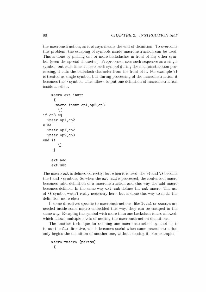
90 CHAPTER 2. INSTRUCTION SET
the macroinstruction, as it always means the end of definition. To overcomethis problem, the escaping of symbols inside macroinstruction can be used.This is done by placing one or more backslashes in front of any other sym-bol (even the special character). Preprocessor sees such sequence as a singlesymbol, but each time it meets such symbol during the macroinstruction pro-cessing, it cuts the backslash character from the front of it. For example \}
is treated as single symbol, but during processing of the macroinstruction itbecomes the } symbol. This allows to put one definition of macroinstructioninside another:
macro ext instr
{
macro instr op1,op2,op3
\{
if op3 eq
instr op1,op2
else
instr op1,op2
instr op2,op3
end if
\}
}
ext add
ext sub
The macro ext is defined correctly, but when it is used, the \{ and \} becomethe { and } symbols. So when the ext add is processed, the contents of macrobecomes valid definition of a macroinstruction and this way the add macrobecomes defined. In the same way ext sub defines the sub macro. The useof \{ symbol wasn’t really necessary here, but is done this way to make thedefinition more clear.
If some directives specific to macroinstructions, like local or common areneeded inside some macro embedded this way, they can be escaped in thesame way. Escaping the symbol with more than one backslash is also allowed,which allows multiple levels of nesting the macroinstruction definitions.
The another technique for defining one macroinstruction by another isto use the fix directive, which becomes useful when some macroinstructiononly begins the definition of another one, without closing it. For example:
macro tmacro [params]
{

2.3. PREPROCESSOR DIRECTIVES 91
common macro params {
}
MACRO fix tmacro
ENDM fix }
defines an alternative syntax for defining macroinstructions, which looks like:
MACRO stoschar char
mov al,char
stosb
ENDM
Note that symbol that has such customized definition must be defined withfix directive, because only the prioritized symbolic constants are processedbefore the preprocessor looks for the } character while defining the macro.This might be a problem if one needed to perform some additional tasksone the end of such definition, but there is one more feature which helpsin such cases. Namely it is possible to put any directive, instruction ormacroinstruction just after the } character that ends the macroinstructionand it will be processed in the same way as if it was put in the next line.
2.3.4 Structures
struc directive is a special variant of macro directive that is used to definedata structures. Macroinstruction defined using the struc directive mustbe preceded by a label (like the data definition directive) when it’s used.This label will be also attached at the beginning of every name starting withdot in the contents of macroinstruction. The macroinstruction defined usingthe struc directive can have the same name as some other macroinstructiondefined using the macro directive, structure macroinstruction won’t preventthe standard macroinstruction being processed when there is no label beforeit and vice versa. All the rules and features concerning standard macroin-structions apply to structure macroinstructions.
Here is the sample of structure macroinstruction:
struc point x,y
{
.x dw x
.y dw y
}

92 CHAPTER 2. INSTRUCTION SET
For example my point 7,11 will define structure labeled my, consisting oftwo variables: my.x with value 7 and my.y with value 11.
If somewhere inside the definition of structure the name consisting of asingle dot it found, it is replaced by the name of the label for the giveninstance of structure and this label will not be defined automatically in suchcase, allowing to completely customize the definition. The following exampleutilizes this feature to extend the data definition directive db with ability tocalculate the size of defined data:
struc db [data]
{
common
. db data
.size = $ - .
}
With such definition msg db ’Hello!’,13,10 will define also msg.size con-stant, equal to the size of defined data in bytes.
Defining data structures addressed by registers or absolute values shouldbe done using the virtual directive with structure macroinstruction (see2.2.5).
restruc directive removes the last definition of the structure, just likepurge does with macroinstructions and restore with symbolic constants.It also has the same syntax – should be followed by one or more names ofstructure macroinstructions, separated with commas.
2.3.5 Repeating macroinstructions
The rept directive is a special kind of macroinstruction, which makes givenamount of duplicates of the block enclosed with braces. The basic syntax isrept directive followed by number and then block of source enclosed betweenthe { and } characters. The simplest example:
rept 5 { in al,dx }
will make five duplicates of the in al,dx line. The block of instructions isdefined in the same way as for the standard macroinstruction and any specialoperators and directives which can be used only inside macroinstructionsare also allowed here. When the given count is zero, the block is simplyskipped, as if you defined macroinstruction but never used it. The numberof repetitions can be followed by the name of counter symbol, which will getreplaced symbolically with the number of duplicate currently generated. Sothis:

2.3. PREPROCESSOR DIRECTIVES 93
rept 3 counter
{
byte#counter db counter
}
will generate lines:
byte1 db 1
byte2 db 2
byte3 db 3
The repetition mechanism applied to rept blocks is the same as the one usedto process multiple groups of arguments for macroinstructions, so directiveslike forward, common and reverse can be used in their usual meaning. Thussuch macroinstruction:
rept 7 num { reverse display ‘num }
will display digits from 7 to 1 as text. The local directive behaves in thesame way as inside macroinstruction with multiple groups of arguments, so:
rept 21
{
local label
label: loop label
}
will generate unique label for each duplicate.The counter symbol by default counts from 1, but you can declare different
base value by placing the number preceded by colon immediately after thename of counter. For example:
rept 8 n:0 { pxor xmm#n,xmm#n }
will generate code which will clear the contents of eight SSE registers. Youcan define multiple counters separated with commas, and each one can havedifferent base.
The number of repetitions and the base values for counters can be spec-ified using the numerical expressions with operator rules identical as in thecase of assembler. However each value used in such expression must eitherbe a directly specified number, or a symbolic constant with value also beingan expression that can be calculated by preprocessor (in such case the valueof expression associated with symbolic constant is calculated first, and thensubstituted into the outer expression in place of that constant). If you need

94 CHAPTER 2. INSTRUCTION SET
repetitions based on values that can only be calculated at assembly time,use one of the code repeating directives that are processed by assembler, seesection 2.2.3.
The irp directive iterates the single argument through the given list ofparameters. The syntax is irp followed by the argument name, then thecomma and then the list of parameters. The parameters are specified in thesame way like in the invocation of standard macroinstruction, so they haveto be separated with commas and each one can be enclosed with the < and> characters. Also the name of argument may be followed by * to mark thatit cannot get an empty value. Such block:
irp value, 2,3,5
{ db value }
will generate lines:
db 2
db 3
db 5
The irps directive iterates through the given list of symbols, it should befollowed by the argument name, then the comma and then the sequence ofany symbols. Each symbol in this sequence, no matter whether it is the namesymbol, symbol character or quoted string, becomes an argument value forone iteration. If there are no symbols following the comma, no iteration isdone at all. This example:
irps reg, al bx ecx
{ xor reg,reg }
will generate lines:
xor al,al
xor bx,bx
xor ecx,ecx
The blocks defined by the irp and irps directives are also processed in thesame way as any macroinstructions, so operators and directives specific tomacroinstructions may be freely used also in this case.
2.3.6 Conditional preprocessing
match directive causes some block of source to be preprocessed and passedto assembler only when the given sequence of symbols matches the specified

2.3. PREPROCESSOR DIRECTIVES 95
pattern. The pattern comes first, ended with comma, then the symbols thathave to be matched with the pattern, and finally the block of source, enclosedwithin braces as macroinstruction.
There are the few rules for building the expression for matching, firstis that any of symbol characters and any quoted string should be matchedexactly as is. In this example:
match +,+ { include ’first.inc’ }
match +,- { include ’second.inc’ }
the first file will get included, since + after comma matches the + in pattern,and the second file won’t be included, since there is no match.
To match any other symbol literally, it has to be preceded by = characterin the pattern. Also to match the = character itself, or the comma, the ==
and =, constructions have to be used. For example the =a== pattern willmatch the a= sequence.
If some name symbol is placed in the pattern, it matches any sequenceconsisting of at least one symbol and then this name is replaced with thematched sequence everywhere inside the following block, analogously to theparameters of macroinstruction. For instance:
match a-b, 0-7
{ dw a,b-a }
will generate the dw 0,7-0 instruction. Each name is always matched withas few symbols as possible, leaving the rest for the following ones, so in thiscase:
match a b, 1+2+3 { db a }
the a name will match the 1 symbol, leaving the +2+3 sequence to be matchedwith b. But in this case:
match a b, 1 { db a }
there will be nothing left for b to match, so the block won’t get processed atall.
The block of source defined by match is processed in the same way as anymacroinstruction, so any operators specific to macroinstructions can be usedalso in this case.
What makes ”match” directive more useful is the fact, that it replacesthe symbolic constants with their values in the matched sequence of symbols(that is everywhere after comma up to the beginning of the source block)before performing the match. Thanks to this it can be used for example toprocess some block of source under the condition that some symbolic constanthas the given value, like:

96 CHAPTER 2. INSTRUCTION SET
match =TRUE, DEBUG { include ’debug.inc’ }
which will include the file only when the symbolic constant DEBUG was definedwith value TRUE.
2.3.7 Order of processing
When combining various features of the preprocessor, it’s important to knowthe order in which they are processed. As it was already noted, the highestpriority has the fix directive and the replacements defined with it. This isdone completely before doing any other preprocessing, therefore this piece ofsource:
V fix {
macro empty
V
V fix }
V
becomes a valid definition of an empty macroinstruction. It can be inter-preted that the fix directive and prioritized symbolic constants are processedin a separate stage, and all other preprocessing is done after on the resultingsource.
The standard preprocessing that comes after, on each line begins withrecognition of the first symbol. It starts with checking for the preprocessordirectives, and when none of them is detected, preprocessor checks whetherthe first symbol is macroinstruction. If no macroinstruction is found, it movesto the second symbol of line, and again begins with checking for directives,which in this case is only the equ directive, as this is the only one that occursas the second symbol in line. If there is no directive, the second symbol ischecked for the case of structure macroinstruction and when none of thosechecks gives the positive result, the symbolic constants are replaced withtheir values and such line is passed to the assembler.
To see it on the example, assume that there is defined the macroinstruc-tion called foo and the structure macroinstruction called bar. Those lines:
foo equ
foo bar
would be then both interpreted as invocations of macroinstruction foo, sincethe meaning of the first symbol overrides the meaning of second one.
2.3. PREPROCESSOR DIRECTIVES 97
When the macroinstruction generates the new lines from its definitionblock, in every line it first scans for macroinstruction directives, and inter-pretes them accordingly. All the other content in the definition block is usedto brew the new lines, replacing the parameters with their values and thenprocessing the symbol escaping and # and ‘ operators. The conversion opera-tor has the higher priority than concatenation and if any of them operates onthe escaped symbol, the escaping is cancelled before finishing the operation.After this is completed, the newly generated line goes through the standardpreprocessing, as described above.
Though the symbolic constants are usually only replaced in the lines,where no preprocessor directives nor macroinstructions has been found, thereare some special cases where those replacements are performed in the partsof lines containing directives. First one is the definition of symbolic constant,where the replacements are done everywhere after the equ keyword and theresulting value is then assigned to the new constant (see 2.3.2). The secondsuch case is the match directive, where the replacements are done in thesymbols following comma before matching them with pattern. These featurescan be used for example to maintain the lists, like this set of definitions:
list equ
macro append item
{
match any, list \{ list equ list,item \}
match , list \{ list equ item \}
}
The list constant is here initialized with empty value, and the append
macroinstruction can be used to add the new items into this list, separatingthem with commas. The first match in this macroinstruction occurs onlywhen the value of list is not empty (see 2.3.6), in such case the new value forthe list is the previous one with the comma and the new item appended atthe end. The second match happens only when the list is still empty, and insuch case the list is defined to contain just the new item. So starting withthe empty list, the append 1 would define list equ 1 and the append 2
following it would define list equ 1,2. One might then need to use this listas the parameters to some macroinstruction. But it cannot be done directly– if foo is the macroinstruction, then foo list would just pass the list
symbol as a parameter to macro, since symbolic constants are not unrolledat this stage. For this purpose again match directive comes in handy:
match params, list { foo params }

98 CHAPTER 2. INSTRUCTION SET
The value of list, if it’s not empty, matches the params keyword, which isthen replaced with matched value when generating the new lines defined bythe block enclosed with braces. So if the list had value 1,2, the above linewould generate the line containing foo 1,2, which would then go throughthe standard preprocessing.
There is one more special case – when preprocessor goes to checking thesecond symbol in the line and it happens to be the colon character (what isthen interpreted by assembler as definition of a label), it stops in this placeand finishes the preprocessing of the first symbol (so if it’s the symbolicconstant it gets unrolled) and if it still appears to be the label, it performsthe standard preprocessing starting from the place after the label. Thisallows to place preprocessor directives and macroinstructions after the labels,analogously to the instructions and directives processed by assembler, like:
start: include ’start.inc’
However if the label becomes broken during preprocessing (for example whenit is the symbolic constant with empty value), only replacing of the symbolicconstants is continued for the rest of line.
It should be remembered, that the jobs performed by preprocessor arethe preliminary operations on the texts symbols, that are done in a simplesingle pass before the main process of assembly. The text that is the result ofpreprocessing is passed to assembler, and it then does its multiple passes onit. Thus the control directives, which are recognized and processed only bythe assembler – as they are dependent on the numerical values that may evenvary between passes – are not recognized in any way by the preprocessor andhave no effect on the preprocessing. Consider this example source:
if 0
a = 1
b equ 2
end if
dd b
When it is preprocessed, they only directive that is recognized by the pre-processor is the equ, which defines symbolic constant b, so later in the sourcethe b symbol is replaced with the value 2. Except for this replacement, theother lines are passes unchanged to the assembler. So after preprocessing theabove source becomes:
if 0
a = 1
end if
dd 2

2.4. FORMATTER DIRECTIVES 99
Now when assembler processes it, the condition for the if is false, and thea constant doesn’t get defined. However symbolic constant b was processednormally, even though its definition was put just next to the one of a. Sobecause of the possible confusion you should be very careful every time whenmixing the features of preprocessor and assembler - in such cases it is impor-tant to realize what the source will become after the preprocessing, and thuswhat the assembler will see and do its multiple passes on.
2.4 Formatter directives
These directives are actually also a kind of control directives, with the pur-pose of controlling the format of generated code.
format directive followed by the format identifier allows to select theoutput format. This directive should be put at the beginning of the source.Default output format is a flat binary file, it can also be selected by usingformat binary directive. This directive can be followed by the as keywordand the quoted string specifying the default file extension for the output file.Unless the output file name was specified from the command line, assemblerwill use this extension when generating the output file.
use16 and use32 directives force the assembler to generate 16–bit or32–bit code, omitting the default setting for selected output format. use64
enables generating the code for the long mode of x86–64 processors.Below are described different output formats with the directives specific
to these formats.
2.4.1 MZ executable
To select the MZ output format, use format MZ directive. The default codesetting for this format is 16–bit.
segment directive defines a new segment, it should be followed by label,which value will be the number of defined segment, optionally use16 or use32word can follow to specify whether code in this segment should be 16–bit or32–bit. The origin of segment is aligned to paragraph (16 bytes). All thelabels defined then will have values relative to the beginning of this segment.
entry directive sets the entry point for MZ executable, it should be fol-lowed by the far address (name of segment, colon and the offset inside seg-ment) of desired entry point.
stack directive sets up the stack for MZ executable. It can be followed bynumerical expression specifying the size of stack to be created automaticallyor by the far address of initial stack frame when you want to set up the stack

100 CHAPTER 2. INSTRUCTION SET
manually. When no stack is defined, the stack of default size 4096 bytes willbe created.
heap directive should be followed by a 16–bit value defining maximumsize of additional heap in paragraphs (this is heap in addition to stack andundefined data). Use heap 0 to always allocate only memory program reallyneeds. Default size of heap is 65535.
2.4.2 Portable Executable
To select the Portable Executable output format, use format PE directive,it can be followed by additional format settings: first the target subsystemsetting, which can be console or GUI for Windows applications, native
for Windows drivers, EFI, EFIboot or EFIruntime for the UEFI, it may befollowed by the minimum version of system that the executable is targetedto (specified in form of floating-point value). Optional DLL and WDM keywordsmark the output file as a dynamic link library and WDM driver respectively,and the large keyword marks the executable as able to handle addresseslarger than 2 GB.
After those settings can follow the at operator and the numerical ex-pression specifying the base of PE image and then optionally on operatorfollowed by the quoted string containing file name selects custom MZ stubfor PE program (when specified file is not a MZ executable, it is treated as aflat binary executable file and converted into MZ format). The default codesetting for this format is 32–bit. The example of fully featured PE formatdeclaration:
format PE GUI 4.0 DLL at 7000000h on ’stub.exe’
To create PE file for the x86–64 architecture, use PE64 keyword insteadof PE in the format declaration, in such case the long mode code is generatedby default.
section directive defines a new section, it should be followed by quotedstring defining the name of section, then one or more section flags can fol-low. Available flags are: code, data, readable, writeable, executable,shareable, discardable, notpageable. The origin of section is aligned topage (4096 bytes). Example declaration of PE section:
section ’.text’ code readable executable
Among with flags also on of special PE data identifiers can be specified tomark the whole section as a special data, possible identifiers are export,import, resource and fixups. If the section is marked to contain fixups,

2.4. FORMATTER DIRECTIVES 101
they are generated automatically and no more data needs to be defined inthis section. Also resource data can be generated automatically from theresource file, it can be achieved by writing the from operator and quotedfile name after the resource identifier. Below are the examples of sectionscontaining some special PE data:
section ’.reloc’ data discardable fixups
section ’.rsrc’ data readable resource from ’my.res’
entry directive sets the entry point for Portable Executable, the value ofentry point should follow.
stack directive sets up the size of stack for Portable Executable, value ofstack reserve size should follow, optionally value of stack commit separatedwith comma can follow. When stack is not defined, it’s set by default to sizeof 4096 bytes.
heap directive chooses the size of heap for Portable Executable, value ofheap reserve size should follow, optionally value of heap commit separatedwith comma can follow. When no heap is defined, it is set by default to sizeof 65536 bytes, when size of heap commit is unspecified, it is by default setto zero.
data directive begins the definition of special PE data, it should be fol-lowed by one of the data identifiers (export, import, resource or fixups)or by the number of data entry in PE header. The data should be definedin next lines, ended with end data directive. When fixups data definitionis chosen, they are generated automatically and no more data needs to bedefined there. The same applies to the resource data when the resource
identifier is followed by from operator and quoted file name – in such casedata is taken from the given resource file.
The rva operator can be used inside the numerical expressions to obtainthe RVA of the item addressed by the value it is applied to, that is the offsetrelative to the base of PE image.
2.4.3 Common Object File Format
To select Common Object File Format, use format COFF or format MS COFF
directive, depending whether you want to create classic (DJGPP) or Mi-crosoft’s variant of COFF file. The default code setting for this format is32-bit. To create the file in Microsoft’s COFF format for the x86-64 ar-chitecture, use format MS64 COFF setting, in such case long mode code isgenerated by default.
section directive defines a new section, it should be followed by quotedstring defining the name of section, then one or more section flags can fol-
102 CHAPTER 2. INSTRUCTION SET
low. Section flags available for both COFF variants are code and data,while flags readable, writeable, executable, shareable, discardable,notpageable, linkremove and linkinfo are available only with Microsoft’sCOFF variant.
By default section is aligned to double word (four bytes), in case of Mi-crosoft COFF variant other alignment can be specified by providing thealign operator followed by alignment value (any power of two up to 8192)among the section flags.
extrn directive defines the external symbol, it should be followed by thename of symbol and optionally the size operator specifying the size of datalabeled by this symbol. The name of symbol can be also preceded by quotedstring containing name of the external symbol and the as operator. Someexample declarations of external symbols:
extrn exit
extrn ’__imp__MessageBoxA@16’ as MessageBox:dword
public directive declares the existing symbol as public, it should be fol-lowed by the name of symbol, optionally it can be followed by the as operatorand the quoted string containing name under which symbol should be avail-able as public. Some examples of public symbols declarations:
public main
public start as ’_start’
Additionally, with COFF format it’s possible to specify exported symbol asstatic, it’s done by preceding the name of symbol with the static keyword.
When using the Microsoft’s COFF format, the rva operator can be usedinside the numerical expressions to obtain the RVA of the item addressed bythe value it is applied to.
2.4.4 Executable and Linkable Format
To select ELF output format, use format ELF directive. The default codesetting for this format is 32–bit. To create ELF file for the x86–64 archi-tecture, use format ELF64 directive, in such case the long mode code isgenerated by default.
section directive defines a new section, it should be followed by quotedstring defining the name of section, then can follow one or both of theexecutable and writeable flags, optionally also align operator followedby the number specifying the alignment of section (it has to be the power oftwo), if no alignment is specified, the default value is used, which is 4 or 8,depending on which format variant has been chosen.

2.4. FORMATTER DIRECTIVES 103
extrn and public directives have the same meaning and syntax as whenthe COFF output format is selected (described in previous section).
The rva operator can be used also in the case of this format (however notwhen target architecture is x86–64), it converts the address into the offsetrelative to the GOT table, so it may be useful to create position-independentcode. There’s also a special plt operator, which allows to call the externalfunctions through the Procedure Linkage Table. You can even create an aliasfor external function that will make it always be called through PLT, withthe code like:
extrn ’printf’ as _printf
printf = PLT _printf
To create executable file, follow the format choice directive with theexecutable keyword and optionally the number specifying the brand of thetarget operating system (for example value 3 would mark the executable forLinux systems). With this format selected it is allowed to use entry directivefollowed by the value to set as entry point of program. On the other handit makes extrn and public directives unavailable, and instead of sectionthere should be the segment directive used, followed by one or more segmentpermission flags and optionally a marker of special ELF executable segment,which can be interpreter, dynamic or note. The origin of segment isaligned to page (4096 bytes), and available permission flags are: readable,writeable and executable.

104 CHAPTER 2. INSTRUCTION SET

Chapter 3
Windows programming
With the Windows version of flat assembler comes the package of standardincludes designed to help in writing the programs for Windows environment.
The includes package contains the headers for 32–bit and 64–bit Windowsprogramming in the root folder and the specialized includes in the subfold-ers. In general, the headers include the required specialized files for you,though sometimes you might prefer to include some of the macroinstructionpackages yourself (since few of them are not included by some or even all ofthe headers).
There are six headers for 32–bit Windows that you can choose from,with names starting with win32 followed by either a letter a for using theASCII encoding, or a letter w for the WideChar encoding. The win32a.inc
and win32w.inc are the basic headers, the win32ax.inc and win32wx.inc
are the extended headers, they provide more advanced macroinstructions,those extensions will be discussed separately. Finally the win32axp.inc
and win32wxp.inc are the same extended headers with enabled feature ofchecking the count of parameters in procedure calls.
There are analogous six packages for the 64–bit Windows, with namesstarting with win64. They provide in general the same functionality as theones for 32–bit Windows, with just a few differences explained later.
You can include the headers any way you prefer, by providing the fullpath or using the custom environment variable, but the simplest method isto define the INCLUDE environment variable properly pointing to the directorycontaining headers and then include them just like:
include ’win32a.inc’
It’s important to note that all macroinstructions, as opposed to internaldirectives of flat assembler, are case sensitive and the lower case is used for
105

106 CHAPTER 3. WINDOWS PROGRAMMING
the most of them. If you’d prefer to use the other case than default, youshould do the appropriate adjustments with fix directive.
3.1 Basic headers
The basic headers win32a.inc, win32w.inc, win64a.inc and win64w.inc
include the declarations of Windows equates and structures and provide thestandard set of macroinstructions.
3.1.1 Structures
All headers enable the struct macroinstruction, which allows to define struc-tures in a way more similar to other assemblers than the struc directive. Thedefinition of structure should be started with struct macroinstruction fol-lowed by the name, and ended with ends macroinstruction. In lines betweenonly data definition directives are allowed, with labels being the pure namesfor the fields of structure:
struct POINT
x dd ?
y dd ?
ends
With such definition this line:
point1 POINT
will declare the point1 structure with the point1.x and point1.y fields,giving them the default values – the same ones as provided in the definitionof structure (in this case the defaults are both uninitialized values). Butdeclaration of structure also accepts the parameters, in the same count asthe number of fields in the structure, and those parameters, when specified,override the default values for fields. For example:
point2 POINT 10,20
initializes the point2.x field with value 10, and the point2.y with value 20.The struct macro not only enables to declare the structures of given type,
but also defines labels for offsets of fields inside the structure and constantsfor sized of every field and the whole structure. For example the above defi-nition of POINT structure defines the POINT.x and POINT.y labels to be theoffsets of fields inside the structure, and sizeof.POINT.x, sizeof.POINT.y

3.1. BASIC HEADERS 107
and sizeof.POINT as sizes of the corresponding fields and of the whole struc-ture. The offset labels may be used for accessing the structures addressedindirectly, like:
mov eax,[ebx+POINT.x]
when the ebx register contains the pointer to POINT structure. Note thatfield size checking will be performed with such accessing as well.
The structures itself are also allowed inside the structure definitions, sothe structures may have some other structures as a fields:
struct LINE
start POINT
end POINT
ends
When no default values for substructure fields are specified, as in this exam-ple, the defaults from the definition of the type of substructure apply.
Since value for each field is a single parameter in the declaration of thestructure, to initialize the substructures with custom values the parametersfor each substructure must be grouped into a single parameter for the struc-ture:
line1 LINE <0,0>,<100,100>
This declaration initializes each of the line1.start.x and line1.start.y
fields with 0, and each of the line1.end.x and line1.end.y with 100.When the size of data defined by some value passed to the declaration
structure is smaller than the size of corresponding field, it is padded to thatsize with undefined bytes (and when it is larger, the error happens). Forexample:
struct FOO
data db 256 dup (?)
ends
some FOO <"ABC",0>
fills the first four bytes of some.data with defined values and reserves therest.
Inside the structures also unions and unnamed substructures can be de-fined. The definition of union should start with union and end with ends,like in this example:

108 CHAPTER 3. WINDOWS PROGRAMMING
struct BAR
field_1 dd ?
union
field_2 dd ?
field_2b db ?
ends
ends
Each of the fields defined inside union has the same offset and they sharethe same memory. Only the first field of union is initialized with givenvalue, the values for the rest of fields are ignored (however if one of theother fields requires more memory than the first one, the union is paddedto the required size with undefined bytes). The whole union is initialized bythe single parameter given in structure declaration, and this parameter givesvalue to the first field of union.
The unnamed substructure is defined in a similar way to the union, onlystarts with the struct line instead of union, like:
struct WBB
word dw ?
struct
byte1 db ?
byte2 db ?
ends
ends
Such substructure only takes one parameter in the declaration of whole struc-ture to define its values, and this parameter can itself be the group of param-eters defining each field of the substructure. So the above type of structuremay get declared like:
my WBB 1,<2,3>
The fields inside unions and unnamed substructures are accessed just as ifthe were directly the fields of the parent structure. For example with abovedeclaration my.byte1 and my.byte2 are correct labels for the substructurefields.
The substructures and unions can be nested with no limits for the nestingdepth:
struct LINE
union
start POINT

3.1. BASIC HEADERS 109
struct
x1 dd ?
y1 dd ?
ends
ends
union
end POINT
struct
x2 dd ?
y2 dd ?
ends
ends
ends
The definition of structure may also be based on some of the alreadydefined structure types and it inherits all the fields from that structure, forexample:
struct CPOINT POINT
color dd ?
ends
defines the same structure as:
struct CPOINT
x dd ?
y dd ?
color dd ?
ends
All headers define the CHAR data type, which can be used to define char-acter strings in the data structures.
3.1.2 Imports
The import macroinstructions help to build the import data for PE file (usu-ally put in the separate section). There are two macroinstructions for thispurpose. The first one is called library, must be placed directly in the be-ginning of the import data and it defines from what libraries the functionswill be imported. It should be followed by any amount of the pairs of pa-rameters, each pair being the label for the table of imports from the givenlibrary, and the quoted string defining the name of the library. For example:

110 CHAPTER 3. WINDOWS PROGRAMMING
library kernel32,’KERNEL32.DLL’,\
user32,’USER32.DLL’
declares to import from the two libraries. For each of libraries, the table ofimports must be then declared somewhere inside the import data. This isdone with import macroinstruction, which needs first parameter to define thelabel for the table (the same as declared earlier to the library macro), andthen the pairs of parameters each containing the label for imported pointerand the quoted string defining the name of function exactly as exported bylibrary. For example the above library declaration may be completed withfollowing import declarations:
import kernel32,\
ExitProcess,’ExitProcess’
import user32,\
MessageBeep,’MessageBeep’,\
MessageBox,’MessageBoxA’
The labels defined by first parameters in each pair passed to the import
macro address the double word pointers, which after loading the PE arefilled with the addresses to exported procedures.
Instead of quoted string for the name of procedure to import, the numbermay be given to define import by ordinal, like:
import custom,\
ByName,’FunctionName’,\
ByOrdinal,17
The import macros optimize the import data, so only imports for func-tions that are used somewhere in program are placed in the import tables,and if some import table would be empty this way, the whole library is notreferenced at all. For this reason it’s handy to have the complete import tablefor each library – the package contains such tables for some of the standardlibraries, they are stored in the APIA and APIW subdirectories and importthe ASCII and WideChar variants of the API functions. Each file containsone import table, with lowercase label the same as the name of the file. Sothe complete tables for importing from the KERNEL32.DLL and USER32.DLL
libraries can be defined this way (assuming your INCLUDE environment vari-able points to the directory containing the includes package):
library kernel32,’KERNEL32.DLL’,\
user32,’USER32.DLL’

3.1. BASIC HEADERS 111
include ’apia\kernel32.inc’
include ’apiw\user32.inc’
3.1.3 Procedures (32–bit)
Headers for 32–bit Windows provide four macroinstructions for calling pro-cedures with parameters passed on stack. The stdcall calls directly theprocedure specified by the first argument using the STDCALL calling con-vention. The rest of arguments passed to macro define the parameters toprocedure and are stored on the stack in reverse order. The invoke macrodoes the same, however it calls the procedure indirectly, through the pointerlabelled by the first argument. Thus invoke can be used to call the proce-dures through pointers defined in the import tables. This line:
invoke MessageBox,0,szText,szCaption,MB_OK
is equivalent to:
stdcall [MessageBox],0,szText,szCaption,MB_OK
and they both generate this code:
push MB_OK
push szCaption
push szText
push 0
call [MessageBox]
The ccall and cinvoke are analogous to the stdcall and invoke, butthey should be used to call the procedures that use the C calling convention,where the stack frame has to be restored by the caller.
To define the procedure that uses the stack for parameters and localvariables, you should use the proc macroinstruction. In its simplest form ithas to be followed by the name for the procedure and then names for the allthe parameters it takes, like:
proc WindowProc,hwnd,wmsg,wparam,lparam
The comma between the name of procedure and the first parameter is op-tional. The procedure instructions should follow in the next lines, endedwith the endp macroinstruction. The stack frame is set up automaticallyon the entry to procedure, the EBP register is used as a base to access theparameters, so you should avoid using this register for other purposes. The

112 CHAPTER 3. WINDOWS PROGRAMMING
names specified for the parameters are used to define EBP-based labels, whichyou can use to access the parameters as regular variables. For example themov eax,[hwnd] instruction inside the procedure defined as in above sample,is equivalent to mov eax,[ebp+8]. The scope of those labels is limited tothe procedure, so you may use the same names for other purposes outsidethe given procedure.
Since any parameters are pushed on the stack as double words whencalling such procedures, the labels for parameters are defined to mark thedouble word data by default, however you can you specify the sizes for theparameters if you want, by following the name of parameter with colon andthe size operator. The previous sample can be rewritten this way, which isagain equivalent:
proc WindowProc,hwnd:DWORD,wmsg:DWORD,\
wparam:DWORD,lparam:DWORD
If you specify a size smaller than double word, the given label applies to thesmaller portion of the whole double word stored on stack. If you you specifya larger size, like far pointer of quad word, the two double word parametersare defined to hold this value, but are labelled as one variable.
The name of procedure can be also followed by either the stdcall orc keyword to define the calling convention it uses. When no such type isspecified, the default is used, which is equivalent to STDCALL. Then alsothe uses keyword may follow, and after it the list of registers (separated onlywith spaces) that will be automatically stored on entry to procedure andrestored on exit. In this case the comma after the list of registers and beforethe first parameter is required. So the fully featured procedure statementmight look like this:
proc WindowProc stdcall uses ebx esi edi,\
hwnd:DWORD,wmsg:DWORD,wparam:DWORD,lparam:DWORD
To declare the local variable you can use the local macroinstruction,followed by one or more declarations separated with commas, each one con-sisting of the name for variable followed by colon and the type of variable –either one of the standard types (must be upper case) or the name of datastructure. For example:
local hDC:DWORD,rc:RECT
To declare a local array, you can follow the name of variable by the size ofarray enclosed in square brackets, like:
local str[256]:BYTE

3.1. BASIC HEADERS 113
The other way to define the local variables is to declare them inside the blockstarted with ”locals” macroinstruction and ended with ”endl”, in this casethey can be defined just like regular data. This declaration is the equivalentof the earlier sample:
locals
hDC dd ?
rc RECT
endl
The local variables can be declared anywhere inside the procedure, with theonly limitation that they have to be declared before they are used. The scopeof labels for the variables defined as local is limited to inside the procedure,you can use the same names for other purposes outside the procedure. If yougive some initialized values to the variables declared as local, the macroin-struction generates the instructions that will initialize these variables withthe given values and puts these instruction at the same position in procedure,where the declaration is placed.
The ret placed anywhere inside the procedure, generates the completecode needed to correctly exit the procedure, restoring the stack frame andthe registers used by procedure. If you need to generate the raw returninstruction, use the retn mnemonic, or follow the ret with the numberparameter, what also causes it to be interpreted as single instruction.
To recapitulate, the complete definition of procedure may look like this:
proc WindowProc uses ebx esi edi,hwnd,wmsg,wparam,lparam
local hDC:DWORD,rc:RECT
; the instructions
ret
endp
3.1.4 Procedures (64–bit)
In 64–bit Windows there is only one calling convention, and thus only twomacroinstructions for calling procedures are provided. The fastcall callsdirectly the procedure specified by the first argument using the standardconvention of 64–bit Windows system. The invoke macro does the same,but indirectly, through the pointer labelled by the first argument. Parametersare provided by the arguments that follow, and they can be of any size upto 64 bits. The macroinstructions use RAX register as a temporary storagewhen some parameter value cannot be copied directly into the stack using themov instruction. If the parameter is preceded with addr word, it is treated
114 CHAPTER 3. WINDOWS PROGRAMMING
as an address and is calculated with the lea instruction – so if the addressis absolute, it will get calculated as RIP-relative, thus preventing generatinga relocation in case of file with fixups.
Because in 64–bit Windows the floating–point parameters are passed ina different way, they have to be marked by preceding each one of them withfloat word. They can be either double word or quad word in size. Here isan example of calling some OpenGL procedures with either double–precisionor single–precision parameters:
invoke glVertex3d,float 0.6,float -0.6,float 0.0
invoke glVertex2f,float dword 0.1,float dword 0.2
The stack space for parameters are allocated before each call and freedimmediately after it. However it is possible to allocate this space just oncefor all the calls inside some given block of code, for this purpose there areframe and endf macros provided. They should be used to enclose a block,inside which the RSP register is not altered between the procedure calls andthey prevent each call from allocating stack space for parameters, as it isreserved just once by the frame macro and then freed at the end by the endf
macro.
frame ; allocate stack space just once
invoke TranslateMessage,msg
invoke DispatchMessage,msg
endf
The proc macro for 64–bit Windows has the same syntax and features as 32–bit one (though stdcall and c options are of no use in its case). It should benoted however that in the calling convention used in 64–bit Windows first fourparameters are passed in registers (RCX, RDX, R8 and R9), and therefore,even though there is a space reserved for them at the stack and it is labelledwith name provided in the procedure definition, those four parameters willnot initially reside there. They should be accessed by directly reading theregisters. But if those registers are needed to be used for some other purpose,it is recommended to store the value of such parameter into the memory cellreserved for it. The beginning of such procedure may look like:
proc WindowProc hwnd,wmsg,wparam,lparam
mov [hwnd],rcx
mov [wmsg],edx
mov [wparam],r8
mov [lparam],r9
; now registers can be used for other purpose
; and parameters can still be accessed later

3.1. BASIC HEADERS 115
3.1.5 Customizing procedures
It is possible to create a custom code for procedure framework when usingproc macroinstruction. There are three symbolic variables, prologue@proc,epilogue@proc and close@proc, which define the names of macroinstruc-tions that proc calls upon entry to the procedure, return from procedure (cre-ated with ret macro) and at the end of procedure (made with endp macro).Those variables can be re–defined to point to some other macroinstructions,so that all the code generated with proc macro can be customized.
Each of those three macroinstructions takes five parameters. The first oneprovides a label of procedure entry point, which is the name of procedureaswell. The second one is a bitfield containing some flags, notably the bit 4is set when the caller is supposed to restore the stack, and cleared otherwise.The third one is a value that specifies the number of bytes that parameters tothe procedure take on the stack. The fourth one is a value that specified thenumber of bytes that should be reserved for the local variables. Finally, thefifth an last parameter is the list of comma–separated registers, which pro-cedure declared to be used and which should therefore be saved by prologueand restored by epilogue.
The prologue macro apart from generating code that would set up thestack frame and the pointer to local variables has to define two symbolicvariables, parmbase@proc and localbase@proc. The first one should providethe base address for where the parameters reside, and the second one shouldprovide the address for where the local variables reside – usually relative toEBP/RBP register, but it is possible to use other bases if it can be ensuredthat those pointers will be valid at any point inside the procedure whereparameters or local variables are accessed. It is also up to the prologue macroto make any alignments necessary for valid procedure implementation; thesize of local variables provided as fourth parameter may itself be not alignedat all.
The default behavior of proc is defined by prologuedef and epiloguedef
macros (in default case there is no need for closing macro, so the close@prochas an empty value). If it is needed to return to the defaults after somecustomizations were used, it should be done with the following three lines:
prologue@proc equ prologuedef
epilogue@proc equ epiloguedef
close@proc equ
As an example of modified prologue, below is the macroinstruction thatimplements stack-probing prologue for 32–bit Windows. Such method of

116 CHAPTER 3. WINDOWS PROGRAMMING
allocation should be used every time the area of local variables may getlarger than 4096 bytes.
macro sp_prologue procname,flag,parmbytes,localbytes,reglist
{ local loc
loc = (localbytes+3) and (not 3)
parmbase@proc equ ebp+8
localbase@proc equ ebp-loc
if parmbytes | localbytes
push ebp
mov ebp,esp
if localbytes
repeat localbytes shr 12
mov byte [esp-%*4096],0
end repeat
sub esp,loc
end if
end if
irps reg, reglist \{ push reg \} }
prologue@proc equ sp_prologue
It can be easily modified to use any other stack probing method of the pro-grammer’s preference.
The 64–bit headers provide an additional set of prologue/epilogue macros,which allow to define procedure that uses RSP to access parameters and localvariables (so RBP register is free to use for any other by procedure) and alsoallocates the common space for all the procedure calls made inside, so thatfastcall or invoke macros called do not need to allocate any stack spacethemselves. It is an effect similar to the one obtained by putting the codeinside the procedure into frame block, but in this case the allocation of stackspace for procedure calls is merged with the allocation of space for localvariables. The code inside such procedure must not alter RSP register in anyway. To switch to this behavior of 64–bit proc, use the following instructions:
prologue@proc equ static_rsp_prologue
epilogue@proc equ static_rsp_epilogue
close@proc equ static_rsp_close
3.1.6 Exports
The export macroinstruction constructs the export data for the PE file(it should be either placed in the section marked as export, or within the

3.1. BASIC HEADERS 117
data export block. The first argument should be quoted string defining thename of library file, and the rest should be any number of pairs of arguments,first in each pair being the name of procedure defined somewhere inside thesource, and the second being the quoted string containing the name underwhich this procedure should be exported by the library. This sample:
export ’MYLIB.DLL’,\
MyStart,’Start’,\
MyStop,’Stop’
defines the table exporting two functions, which are defined under the namesMyStart and MyStop in the sources, but will be exported by library under theshorter names. The macroinstruction take care of the alphabetical sorting ofthe table, which is required by PE format.
3.1.7 Component Object Model
The interface macro allows to declare the interface of the COM objecttype, the first parameter is the name of interface, and then the consecutivenames of the methods should follow, like in this example:
interface ITaskBarList,\
QueryInterface,\
AddRef,\
Release,\
HrInit,\
AddTab,\
DeleteTab,\
ActivateTab,\
SetActiveAlt
The comcall macro may be then used to call the method of the givenobject. The first parameter to this macro should be the handle to object, thesecond one should be name of COM interface implemented by this object,and then the name of method and parameters to this method. For example:
comcall ebx,ITaskBarList,ActivateTab,[hwnd]
uses the contents of EBX register as a handle to COM object with theITaskBarList interface, and calls the ActivateTab method of this objectwith the [hwnd] parameter.
You can also use the name of COM interface in the same way as the nameof data structure, to define the variable that will hold the handle to objectof given type:

118 CHAPTER 3. WINDOWS PROGRAMMING
ShellTaskBar ITaskBarList
The above line defines the variable, in which the handle to COM object canbe stored. After storing there the handle to an object, its methods can becalled with the cominvk. This macro needs only the name of the variablewith assigned interface and the name of method as first two parameters,and then parameters for the method. So the ActivateTab method of objectwhose handle is stored in the ShellTaskBar variable as defined above canbe called this way:
cominvk ShellTaskBar,ActivateTab,[hwnd]
which does the same as:
comcall [ShellTaskBar],ITaskBarList,ActivateTab,[hwnd]
3.1.8 Resources
There are two ways to create resources, one is to include the external resourcefile created with some other program, and the other one is to create resourcesection manually. The latter method, though doesn’t need any additionalprogram to be involved, is more laborious, but the standard headers providethe assistance – the set of elementary macroinstructions that serve as bricksto compose the resource section.
The directory macroinstruction must be placed directly in the beginningof manually built resource data and it defines what types of resources itcontains. It should be followed by the pairs of values, the first one in eachpair being the identifier of the type of resource, and the second one the labelof subdirectory of the resources of given type. It may look like this:
directory RT_MENU,menus,\
RT_ICON,icons,\
RT_GROUP_ICON,group_icons
The subdirectories can be placed anywhere in the resource area after themain directory, and they have to be defined with the resource macroin-struction, which requires first parameter to be the label of the subdirectory(corresponding to the entry in main directory) followed by the trios of param-eters – in each such entry the first parameter defines the identifier of resource(this value is freely chosen by the programmer and is then used to access thegiven resource from the program), the second specifies the language and thethird one is the label of resource. Standard equates should be used to createlanguage identifiers. For example the subdirectory of menus may be definedthis way:

3.1. BASIC HEADERS 119
resource menus,\
1,LANG_ENGLISH+SUBLANG_DEFAULT,main_menu,\
2,LANG_ENGLISH+SUBLANG_DEFAULT,other_menu
If the resource is of kind for which the language doesn’t matter, the identifierLANG_NEUTRAL should be used. To define the resources of various types thereare specialized macroinstructions, which should be placed inside the resourcearea.
The bitmaps are the resources with RT_BITMAP type identifier. To definethe bitmap resource use the bitmap macroinstruction with the first parameterbeing the label of resource (corresponding to the entry in the subdirectoryof bitmaps) and the second being the quoted string containing the path tothe bitmap file, like:
bitmap program_logo,’logo.bmp’
The are two resource types related to icons, the RT_GROUP_ICON is thetype for the resource, which has to be linked to one or more resources ofRT_ICON type, each one containing single image. This allows to declare im-ages of different sizes and color depths under the common resource identifier.This identifier, given to the resource of RT_GROUP_ICON type may be thenpassed to the LoadIcon function, and it will choose the image of suitable di-mensions from the group. To define the icon, use the icon macroinstruction,with first parameter being the label of RT_GROUP_ICON resource, followed bythe pairs of parameters declaring the images. First parameter in each pairshould be the label of RT_ICON resource, and the second one the quoted stringcontaining the path to the icon file. In the simplest variant, when group oficon contains just one image, it will look like:
icon main_icon,icon_data,’main.ico’
where the main_icon is the label for entry in resource subdirectory forRT_GROUP_ICON type, and the icon_data is the label for entry of RT_ICONtype.
The cursors are defined in very similar way to icons, this time with theRT_GROUP_CURSOR and RT_CURSOR types and the cursor macro, which takesparameters analogous to those taken by icon macro. So the definition ofcursor may look like this:
cursor my_cursor,cursor_data,’my.cur’
The menus have the RT_MENU type of resource and are defined with themenu macroinstruction followed by few others defining the items inside the
120 CHAPTER 3. WINDOWS PROGRAMMING
menu. The menu itself takes only one parameter – the label of resource.The menuitem defines the item in the menu, it takes up to five parameters,but only two are required – the first one is the quoted string containing thetext for the item, and the second one is the identifier value (which is thevalue that will be returned when user selects the given item from the menu).The menuseparator defines a separator in the menu and doesn’t require anyparameters.
The optional third parameter of menuitem specifies the menu resourceflags. There are two such flags available – MFR_END is the flag for the lastitem in the given menu, and the MFR_POPUP marks that the given item isthe submenu, and the following items will be items composing that submenuuntil the item with MFR_END flag is found. The MFR_END flag can be alsogiven as the parameter to the menuseparator and is the only parameter thismacroinstruction can take. For the menu definition to be complete, everysubmenu must be closed by the item with MFR_END flag, and the whole menumust also be closed this way. Here is an example of complete definition ofthe menu:
menu main_menu
menuitem ’&File’,100,MFR_POPUP
menuitem ’&New’,101
menuseparator
menuitem ’E&xit’,109,MFR_END
menuitem ’&Help’,900,MFR_POPUP + MFR_END
menuitem ’&About...’,901,MFR_END
The optional fourth parameter of menuitem specifies the state flags forthe given item, these flags are the same as the ones used by API functions,like MFS_CHECKED or MFS_DISABLED. Similarly, the fifth parameter can specifythe type flags. For example this will define item checked with a radio–buttonmark:
menuitem ’Selection’,102, ,MFS_CHECKED,MFT_RADIOCHECK
The dialog boxes have the RT_DIALOG type of resource and are definedwith the dialog macroinstruction followed by any number of items definedwith dialogitem ended with the enddialog.
The dialog can take up to eleven parameters, first seven being required.First parameter, as usual, specifies the label of resource, second is the quotedstring containing the title of the dialog box, the next four parameters specifythe horizontal and vertical coordinates, the width and the height of the dialogbox window respectively. The seventh parameter specifies the style flags for

3.1. BASIC HEADERS 121
the dialog box window, the optional eighth one specifies the extended styleflags. The ninth parameter can specify the menu for window – it should bethe identifier of menu resource, the same as one specified in the subdirectoryof resources with RT_MENU type. Finally the tenth and eleventh parametercan be used to define the font for the dialog box – first of them should bethe quoted string containing the name of font, and the latter one the numberdefining the size of font. When these optional parameters are not specified,the default MS Sans Serif of size 8 is used.
This example shows the dialog macroinstruction with all the parametersexcept for the menu (which is left with blank value), the optional ones arein the second line:
dialog about,’About’,50,50,200,100,WS_CAPTION+WS_SYSMENU,\
WS_EX_TOPMOST, ,’Times New Roman’,10
The dialogitem has eight required parameters and one optional. Firstparameter should be the quoted string containing the class name for theitem. Second parameter can be either the quoted string containing text forthe item, or resource identifier in case when the contents of item has to bedefined by some additional resource (like the item of STATIC class with theSS_BITMAP style). The third parameter is the identifier for the item, usedto identify the item by the API functions. Next four parameters specify thehorizontal, vertical coordinates, the width and height of the item respectively.The eighth parameter specifies the style for the item, and the optional ninthspecifies the extended style flags. An example dialog item definition:
dialogitem ’BUTTON’,’OK’,IDOK,8,8,45,15,WS_VISIBLE+WS_TABSTOP
And an example of static item containing bitmap, assuming that there existsa bitmap resource of identifier 7:
dialogitem ’STATIC’,7,0,10,50,50,20,WS_VISIBLE+SS_BITMAP
The definition of dialog resource can contain any amount of items or noneat all, and it should be always ended with enddialog macroinstruction.
The resources of type RT_ACCELERATOR are created with accelerator
macroinstruction. After first parameter traditionally being the label of re-source, there should follow the trios of parameters – the accelerator flagsfollowed by the virtual key code or ASCII character and the identifier value(which is like the identifier of the menu item). A simple accelerator definitionmay look like this:
accelerator main_keys,\
FVIRTKEY+FNOINVERT,VK_F1,901,\
FVIRTKEY+FNOINVERT,VK_F10,109

122 CHAPTER 3. WINDOWS PROGRAMMING
The version information is the resource of type RT_VERSION and is createdwith the versioninfo macroinstruction. After the label of the resource, thesecond parameter specifies the operating system of PE file (usually it shouldbe VOS__WINDOWS32), third parameter the type of file (the most commonare VFT_APP for program and VFT_DLL for library), fourth the subtype (usu-ally VFT2_UNKNOWN), fifth the language identifier, sixth the code page andthen the quoted string parameters, being the pairs of property name andcorresponding value. The simplest version information can be defined like:
versioninfo vinfo,VOS__WINDOWS32,VFT_APP,VFT2_UNKNOWN,\
LANG_ENGLISH+SUBLANG_DEFAULT,0,\
’FileDescription’,’Description of program’,\
’LegalCopyright’,’Copyright et cetera’,\
’FileVersion’,’1.0’,\
’ProductVersion’,’1.0’
Other kinds of resources may be defined with resdata macroinstruction,which takes only one parameter – the label of resource, and can be followedby any instructions defining the data, ended with endres macroinstruction,like:
resdata manifest
file ’manifest.xml’
endres
3.1.9 Text encoding
The resource macroinstructions use the du directive to define any Unicodestrings inside resources – since this directive simply zero extends the char-acters to the 16–bit values, for the strings containing some non–ASCII char-acters, the du may need to be redefined. For some of the encodings themacroinstructions redefining the du to generate the Unicode texts properlyare provided in the ENCODING subdirectory. For example if the source text isencoded with Windows 1250 code page, such line should be put somewherein the beginning of the source:
include ’encoding\win1250.inc’
3.2 Extended headers
The files win32ax.inc, win32wx.inc, win64ax.inc and win64wx.inc pro-vide all the functionality of base headers and include a few more features

3.2. EXTENDED HEADERS 123
involving more complex macroinstructions. Also if no PE format is declaredbefore including the extended headers, the headers declare it automatically.The win32axp.inc, win32wxp.inc, win64axp.inc and win64wxp.inc arethe variants of extended headers, that additionally perform checking thecount of parameters to procedure calls.
3.2.1 Procedure parameters
With the extended headers the macroinstructions for calling procedures allowmore types of parameters than just the double word values as with basicheaders. First of all, when the quoted string is passes as a parameter toprocedure, it is used to define string data placed among the code, and passesto procedure the double word pointer to this string. This allows to easilydefine the strings that don’t have to be re-used, just in the line calling theprocedure that requires pointers to those strings, like:
invoke MessageBox,HWND_DESKTOP,"Message","Caption",MB_OK
If the parameter is the group containing some values separated with commas,it is treated in the same way as simple quoted string parameter.
If the parameter is preceded by the addr word, it means that this value isan address and this address should be passed to procedure, even if it cannotbe done directly – like in the case of local variables, which have addressesrelative to EBP/RBP register. In 32–bit case the EDX register is used tem-porarily to calculate the value of address and pass it to the procedure. Forexample:
invoke RegisterClass,addr wc
in case when the wc is the local variable with address ebp-100h, will generatethis sequence of instructions:
lea edx,[ebp-100h]
push edx
call [RegisterClass]
However when the given address is not relative to any register, it is storeddirectly.
In 64–bit case the addr prefix is allowed even when only standard headersare used, as it can be useful even in case of the regular addresses, because itenforces RIP-relative address calculation.
With 32–bit headers, if the parameter is preceded by the word double, itis treated as 64–bit value and passed to the procedure as two 32–bit param-eters. For example:

124 CHAPTER 3. WINDOWS PROGRAMMING
invoke glColor3d,double 1.0,double 0.1,double 0.1
will pass the three 64–bit parameters as six double words to procedure. Ifthe parameter following double is the memory operand, it should not havesize operator, the double already works as the size override.
Finally, the calls to procedures can be nested, that is call to one proceduremay be used as the parameter to another. In such case the value returnedin EAX/RAX by the nested procedure is passed as the parameter to theprocedure which it is nested in. A sample of such nesting:
invoke MessageBox,<invoke GetTopWindow,[hwnd]>,\
"Message","Caption",MB_OK
There are no limits for the depth of nesting the procedure calls.
3.2.2 Structuring the source
The extended headers enable some macroinstructions that help with easystructuring the program. The .data and .code are just the shortcuts to thedeclarations of sections for data and for the code. The .end macroinstructionshould be put at the end of program, with one parameter specifying the entrypoint of program, and it also automatically generates the import section usingall the standard import tables. In 64–bit Windows the .end automaticallyaligns the stack on 16 bytes boundary.
The .if macroinstruction generates a piece of code that checks for somesimple condition at the execution time, and depending on the result continuesexecution of following block or skips it. The block should be ended with.endif, but earlier also .elseif macroinstruction might be used to beginthe code that will be executed under some additional condition, when theprevious were not met, and the .else as the last before .endif to begin theblock that will be executed when all the conditions were false.
The condition can be specified by using comparison operator – one ofthe =, <, >, <=, >=, and <> – between the two values, first of which mustbe either register or memory operand. The values are compared as unsignedones, unless the comparison expression is preceded by the word signed. Ifyou provide only single value as a condition, it will be tested to be zero, andthe condition will be true only if it’s not. For example:
.if eax
ret
.endif

3.2. EXTENDED HEADERS 125
generates the instructions, which skip over the ret when the EAX is zero.There are also some special symbols recognized as conditions: the ZERO?
is true when the ZF flag is set, in the same way the CARRY?, SIGN?, OVERFLOW?and PARITY? correspond to the state of CF, SF, OF and PF flags.
The simple conditions like above can be composed into complex condi-tional expressions using the &, | operators for conjunction and alternative,the ~ operator for negation, and parenthesis. For example:
.if eax<=100 & ( ecx | edx )
inc ebx
.endif
will generate the compare and jump instructions that will cause the givenblock to get executed only when EAX is below or equal 100 and at the sametime at least one of the ECX and EDX is not zero.
The .while macroinstruction generates the instructions that will repeatexecuting the given block (ended with .endw macroinstruction) as long asthe condition is true. The condition should follow the .while and can bespecified in the same way as for the .if. The pair of .repeat and .until
macroinstructions define the block that will be repeatedly executed until thegiven condition will be met – this time the condition should follow the .untilmacroinstruction, placed at the end of block, like:
.repeat
add ecx,2
.until ecx>100