FARMSCAN jackal
36
area meter batch meter tacho meter rate monitor spray monitor pressure monitor surveillance monitor one monitor, many possibilities FARM SCAN jackal
Transcript of FARMSCAN jackal

area meterbatch metertacho meterrate monitor
spray monitorpressure monitor
surveillance monitor
one monitor, many possibilitiesFARMSCAN jackal


DISCLAIMER
The warranty offered on Farmscan product is limited to the re-pair or replacement of the faulty goods. No liability will be ac-cepted for loss of profit or productivity. WARRANTY IS VOID if power is not connected as described in section 2.4.
NOTE:
Do not mix imperial and metric units when calibrating inputs. Mixing units may result in incorrect results.

J a c k a l
Part Number: AM-Jackal
I
Version 1.0Published: June 1, 2009
Contents
1. GENERAL DESCRIPTION 1
1.1. Technical Specifications . . . . . . . . . . . . . . . . . . . . . . . . . . . . . . . 1
2. Installation 2
2.1. Parts List . . . . . . . . . . . . . . . . . . . . . . . . . . . . . . . . . . . . . . . . . . . 2
2.2. Parts Pictorial . . . . . . . . . . . . . . . . . . . . . . . . . . . . . . . . . . . . . . . 2
2.3. Mounting and Installation . . . . . . . . . . . . . . . . . . . . . . . . . . . . . 2
2.4. Connections . . . . . . . . . . . . . . . . . . . . . . . . . . . . . . . . . . . . . . . . 3
2.4.1. Power Connection . . . . . . . . . . . . . . . . . . . . . . . . . . . . . . . . . . . . . . . . 3
2.4.2. Sensor Compatibility . . . . . . . . . . . . . . . . . . . . . . . . . . . . . . . . . . . . . . 4
3. Operation 5
3.1. Button Functions . . . . . . . . . . . . . . . . . . . . . . . . . . . . . . . . . . . . 5
3.1.1. Power ON / OFF Key . . . . . . . . . . . . . . . . . . . . . . . . . . . . . . . . . . . . . . . 5
3.1.2. Menu Key . . . . . . . . . . . . . . . . . . . . . . . . . . . . . . . . . . . . . . . . . . . . . . . 5
3.1.3. RUN / HOLD Key . . . . . . . . . . . . . . . . . . . . . . . . . . . . . . . . . . . . . . . . . . 5
3.1.4. Soft Keys . . . . . . . . . . . . . . . . . . . . . . . . . . . . . . . . . . . . . . . . . . . . . . . . 6
3.1.5. Navigation Keys . . . . . . . . . . . . . . . . . . . . . . . . . . . . . . . . . . . . . . . . . . 6
3.2. General Operation . . . . . . . . . . . . . . . . . . . . . . . . . . . . . . . . . . . 6
3.2.1. Operation . . . . . . . . . . . . . . . . . . . . . . . . . . . . . . . . . . . . . . . . . . . . . . . 6
3.2.2. Trip . . . . . . . . . . . . . . . . . . . . . . . . . . . . . . . . . . . . . . . . . . . . . . . . . . . . 7
3.2.3. Total . . . . . . . . . . . . . . . . . . . . . . . . . . . . . . . . . . . . . . . . . . . . . . . . . . . 7
3.2.4. System Menu . . . . . . . . . . . . . . . . . . . . . . . . . . . . . . . . . . . . . . . . . . . . 8
3.3. Memory Backup . . . . . . . . . . . . . . . . . . . . . . . . . . . . . . . . . . . . . 8
4. Input Setup 9
4.1. Digital Inputs . . . . . . . . . . . . . . . . . . . . . . . . . . . . . . . . . . . . . . . 9
4.1.1. Speed . . . . . . . . . . . . . . . . . . . . . . . . . . . . . . . . . . . . . . . . . . . . . . . . . . 9
4.1.2. RPM (Shaft Speed) . . . . . . . . . . . . . . . . . . . . . . . . . . . . . . . . . . . . . . . 11
4.1.3. Batch . . . . . . . . . . . . . . . . . . . . . . . . . . . . . . . . . . . . . . . . . . . . . . . . . . 11
4.1.4. Rate . . . . . . . . . . . . . . . . . . . . . . . . . . . . . . . . . . . . . . . . . . . . . . . . . . . 13
4.2. Analogue Inputs . . . . . . . . . . . . . . . . . . . . . . . . . . . . . . . . . . . . 14
4.2.1. Pressure . . . . . . . . . . . . . . . . . . . . . . . . . . . . . . . . . . . . . . . . . . . . . . . . 15
4.2.2. Depth . . . . . . . . . . . . . . . . . . . . . . . . . . . . . . . . . . . . . . . . . . . . . . . . . 17

J a c k a l
Part Number: AM-Jackal
II
Version 1.0Published: June 1, 2009
4.3. Tank / bin level Alarm Inputs . . . . . . . . . . . . . . . . . . . . . . . . . . 19
4.3.1. Features . . . . . . . . . . . . . . . . . . . . . . . . . . . . . . . . . . . . . . . . . . . . . . . 19
4.3.2. Calibration . . . . . . . . . . . . . . . . . . . . . . . . . . . . . . . . . . . . . . . . . . . . . 19
4.4. Run Hold Input . . . . . . . . . . . . . . . . . . . . . . . . . . . . . . . . . . . . . 20
4.4.1. Features . . . . . . . . . . . . . . . . . . . . . . . . . . . . . . . . . . . . . . . . . . . . . . . 20
4.4.2. Calibration . . . . . . . . . . . . . . . . . . . . . . . . . . . . . . . . . . . . . . . . . . . . . 20
5. Example Configurations 21
5.1. Area Meter . . . . . . . . . . . . . . . . . . . . . . . . . . . . . . . . . . . . . . . . 21
5.1.1. Setup procedure . . . . . . . . . . . . . . . . . . . . . . . . . . . . . . . . . . . . . . . . . 21
5.2. Tacho Meter . . . . . . . . . . . . . . . . . . . . . . . . . . . . . . . . . . . . . . . 22
5.2.1. Setup procedure . . . . . . . . . . . . . . . . . . . . . . . . . . . . . . . . . . . . . . . . . 22
5.3. Flow Meter . . . . . . . . . . . . . . . . . . . . . . . . . . . . . . . . . . . . . . . . 23
5.3.1. Setup procedure . . . . . . . . . . . . . . . . . . . . . . . . . . . . . . . . . . . . . . . . . 23
5.4. Batch Meter . . . . . . . . . . . . . . . . . . . . . . . . . . . . . . . . . . . . . . . 23
5.4.1. Setup procedure . . . . . . . . . . . . . . . . . . . . . . . . . . . . . . . . . . . . . . . . . 23
5.5. Airseeder Surveillance Monitor . . . . . . . . . . . . . . . . . . . . . . . . 24
5.5.1. Setup procedure . . . . . . . . . . . . . . . . . . . . . . . . . . . . . . . . . . . . . . . . . 24
6. Sensor installation 26
6.1. Sensor Compatibility Chart . . . . . . . . . . . . . . . . . . . . . . . . . . . 26
6.2. Compatible Sensor Kits . . . . . . . . . . . . . . . . . . . . . . . . . . . . . . 27
6.3. Installing Sensor Kits . . . . . . . . . . . . . . . . . . . . . . . . . . . . . . . . 28
6.3.1. Two Wire ‘Reed’ Sensor Kits . . . . . . . . . . . . . . . . . . . . . . . . . . . . . . . 28
6.3.2. Three Wire ‘Reed’ Sensor Kits . . . . . . . . . . . . . . . . . . . . . . . . . . . . . . 28
6.3.3. Two Wire ‘Coil’ Sensor Kits . . . . . . . . . . . . . . . . . . . . . . . . . . . . . . . . 29
6.3.4. Three Wire Analog Sensor Kits . . . . . . . . . . . . . . . . . . . . . . . . . . . . . 29
6.3.5. Bin / Tank Level Sensor Kits . . . . . . . . . . . . . . . . . . . . . . . . . . . . . . . . 30
6.3.6. Remote Run/Hold Kit . . . . . . . . . . . . . . . . . . . . . . . . . . . . . . . . . . . . . 30

J a c k a l
Part Number: AM-Jackal
1
Version 1.0Published: June 1, 2009
GENERAL DESCRIPTION1. The Jackal is designed as a multifunctional monitor, capable of many tasks, from a simple Area Meter, Flow Meter or Batch Meter to a monitor for 4 bin / tank Airseeders monitoring several shafts, air pressure and tyne / plow depth. There are a total of 13 inputs available which are combined with a single output for emergency shut down and simple batching functions. The inputs can have both high and low alarm thresholds set which can trigger emergency shutdown systems. The unit employs a 64 x 128 pixel graphic LCD to provide large legible characters on the main display and enable calibration data to be clear and descriptive.
There are 10 trip counters as well as an overall total allowing the operator to track numerous jobs in a period of work. The Jackal can be put ‘on hold’ by the operator or by a suitable signal from the machinery, so that periods of machine operation that should not accumulate as a work total can be excluded from trip totals.
Calibration is simplified with the ability to enter either a FACTOR (pulses per unit) or simply drive/run a set amount whilst the unit is counting the pulses and letting the system calculate its own FACTOR. Each input can be used to display information using imperial and metric units, however METRIC AND IMPERIAL uNITS ShOuLD NOT bE MIxED.
TEChNICAL SPECIfICATIONS1.1.
Power Requirements 9 – 16 VDC @ 250mA
Display 128x64 Mono Graphic LCD
Operating Temperature 0 to 50C
Storage Temperature -5 to 65C
Dimensions 135mm x 100mm x 30mm (HxWxD)
Sensor Inputs 13
Input 1 Up to 400 pulses per second .
Inputs 2 – 6 Up to 1000 pulses per second.
Inputs 7 – 8 Analog Voltage 0 – 5V
Inputs 9 – 13 On/Off: 0V or 12V
Outputs 1
Output 1 Low side drive 3A maximum load.
WARRANTY IS VOID if storage temperature is exceeded. Tractor cabs may exceed 65C if left in full sun when not in operation. Remove the Jackal from the cab if this is a possibility.
!WARNING

J a c k a l
Part Number: AM-Jackal
2
Version 1.0Published: June 1, 2009
2 . I N S T A L L A T I O N
2. INSTALLATION
PARTS LIST2.1.
PARTS PICTORIAL2.2.
REF PART NO. DESCRIPTION QTY1 A-Jackal JACKAL MONITOR 1
2 AH-700 MOUNTING BRACKET 1
3 P-321 11 WAY INPUT PLUG 2
4 AC-103 5m POWER CABLE 1
5 HM-410 SCREWDRIVER 1
6 AM-Jackal INSTRUCTION MANUAL 1
7 AM-200 FARMSCAN WARRANTY CARD 1
8 P-322 FERRULES 10
MOuNTING AND INSTALLATION2.3. The Jackal is provided with a suction window mount. (Figure 1)
Slide mount onto unit and push sideways to lock into place. Make sure you hear a click 1. of the mount locking into place.Place in a convenient position on the windscreen and using the toggle lever pictured, 2. push all the way to the bottom until lever locks into position.
Note: Monitor should be mounted in a clearly visible position in the cab for the operator, but not in a position where it is subject to intense heat or moisture.
Parts pictorial with parts numbered as per Section 2.1.Figure 1:
15
26
73
4
8

J a c k a l
Part Number: AM-Jackal
3
Version 1.0Published: June 1, 2009
2 . I N S T A L L A T I O N
CONNECTIONS2.4. The connector on the rear of the Jackal has the following function:
POWER CONNECTION2.4.1. Power connection must come direct from battery ter-minals. WARRANTY IS VOID if power is not connect-ed as described in this section.
Connect power cable supplied (Figure 1) 1. DIRECTLY TO bATTERY, as described in Figures 2 and 3.
Ring terminals are used for battery •connection and the end with Ferrules attached (See Figure 1) is used to connect to the Jackal.Connect Ground to • bATT -VE, Terminal B11 using the black wire, as shown in Figure 2.Connect +12 Volts (+battery terminal) to •bATT +VE, Terminal B10 using the red wire as shown in Figure 2Ensure that the battery connection to the •Jackal is 12V as shown in figure 3.CONNECTING 24V TO ThE JACkAL •WILL DAMAGE ThE uNIT AND VOID WARRANTY.
On the plug you will see a small screw on the 2. top. Screw clockwise until the wire is clamped tightly into the plug.
Power Connection at the rear of the Figure 2: Jackal. Red is +12V, Black is Ground (Earth or Common)
B1 B2 B3 B4 B5 B6 B7 B8 B9 B10 B11
A1 A2 A3 A4 A5 A6 A7 A8 A9 A10 A11
Disconnect the terminal plugs from the Jackal if ARC
WELDING on machinery.
!WARNING
A1 GND (Ground/Earth/0V) B1 IN1 (Coil/Prox/Reed sensor)
A2 IN13 (Run hold) B2 IN2 (Prox/Reed sensor)
A3 IN12 (Alarm/Switching sensor) B3 IN3 (Prox/Reed sensor)
A4 IN11 (Alarm/Switching sensor) B4 IN4 (Prox/Reed sensor)
A5 IN10 (Alarm/Switching sensor) B5 IN5 (Prox/Reed sensor)
A6 IN9 (Alarm/Switching sensor) B6 IN6 (Prox/Reed sensor)
A7 IN8 (Varying volt sensor) B7 IN7 (Varying volt sensor)
A8 CANbuS hI B8 OuT1 (Solenoid/Shutoff output )
A9 CANbuS LO B9 OuT2 (Regulated +12V output)
A10 RS232 Tx B10 bATT +VE (+12V Battery Terminal)
A11 RS232 Rx B11bATT -VE (0V/GND Battery Ter-minal, Vehicle Ground)

J a c k a l
Part Number: AM-Jackal
4
Version 1.0Published: June 1, 2009
3 . O P E R A T I O N
SENSOR COMPATIbILITY2.4.2. The Farmscan sensors that are compatible with these inputs are shown in the table below. For
detail on Sensor Kits or how to connect the specific sensors see section 6.
Correct battery connection for possible battery configurationsFigure 3:
BATTERY CONNECTION
TWO 6 VOLTBATTERIES
+12VVEHICLE
+-- +
BATT GND
BATT +12VJACKAL
(RED)
(BLACK)
POWERGROUND
TWO 12 VOLT BATTERIES
+24V
+12V+-
+-
BATT GND
BATT +12VJACKAL
(RED)
(BLACK)
VEHICLEPOWERGROUND
(0V)
ONE 12 VOLT BATTERY
+12V
+GND-
BATT GND
BATT +12VJACKAL
(RED)
(BLACK)
VEHICLEPOWER
GROUND
SensorOptions 1007P
1009P
1010
1501
2034
2076
2077
2202
A-2220P
A-2080P
AA
-2009P
AA
-122P
AA
-1 25
AA
-242
AA
-230
AA
-210
AA
-232
AA
-231
Name TerminalInputs
1 B1 • • • • • • • • • • • •
2 – 6 B2 – B6 • • • • • • • • •
7 – 8 A7 & B7 •
9 – 12 A3 – A6 • •
Output1 B8 •

J a c k a l
Part Number: AM-Jackal
5
Version 1.0Published: June 1, 2009
3 . O P E R A T I O N
OPERATION3.
BuTTON fuNCTIONS3.1.
POWER ON / OFF kEY3.1.1. Power is turned on by a short press of the on/off key (1 second). Power is turned off by two short presses.
MENu kEY3.1.2. The MEnU key is used for setting up the ports as well as returning to the main screen from TRIPS or TOTAL displays.
RuN / hOLD kEY3.1.3. The RUn/HoLD key has a dual function. Press RUn/HoLD once to place the ‘MONITOR ON HOLD’. Press RUn/HoLD again to resume operation.
When in hOLD mode, all alarms and accumulating readouts such as AREA and DISTANCE are stopped and any solenoid attached to OuTPuT 1 (Terminal A4) will be deactivated. The monitor will beep an alarm every 10 seconds to remind the operator everything is on hold, and therefore not recording data.
The RuN/hOLD state is indicated in the top right hand corner of the screen. When the monitor is in RuN mode, a little bar rotates in the top right corner to signify that the monitor is active. When the monitor is in hOLD mode this bar is not visible and “ON HOLD” is displayed at the top of the screen.
MENU
RUN/HOLD
SOFTKEYS
NAV KEYS
ON/OFF
Button names as used in this document.Figure 4:

J a c k a l
Part Number: AM-Jackal
6
Version 1.0Published: June 1, 2009
3 . O P E R A T I O N
REMOTE RuN/hOLD3.1.3.1. As an alternative to manually activating the RUn/HoLD key you can automatically place the monitor on hold by connecting Input 13 to any electrical device (e.g. clutch switch) that is acti-vated whenever the machine is operational. Input 13 can be programmed for RuN signal level to be high (12 volts) or low (0 volts).
A remote RUn/HoLD button can also be purchased if the monitor is not within easy reach of the operator.
NOTE: If connection to remote RUn/HoLD switch is faulty the signal will be read as high (12V) and the Jackal will behave accordingly.
SOFT kEYS3.1.4. The Jackal has 3 soft keys placed directly under the LCD. These keys will change function in different menus. The current function of the soft key is indicated at the bottom of the screen directly above the button. In the main menu the soft keys provide access to information display MoDE, ToTAL and TRIP memories as described in subsequent sections.
NAVIGATION kEYS3.1.5. The Round navigation (nAV) keys are used to navigate UP/DoWn and LEfT/RIGHT in calibration screens. EnTER is used to activate the selection.
GENERAL OPERATION3.2. The Jackal has 5 kinds of screen displays: Operation; Trip; Total; Input Calibration; and System. Input Calibration is discussed in detail in section 4.
OPERATION3.2.1. Operation screens show live information and alarms, measured using the sensors attached to the Jackal. The Jackal can display two pieces of live information at a time. If more than two pieces of information are available, the MoDE softkey can be used to cycle through the available information, as described below. The first operation screen is referred to as the main screen, and is generally used as the starting point for examples and operational descriptions in this manual.
MODE3.2.1.1. The Jackal displays two pieces of live information in addition to alarms (if any) and softkey options when in operation. This is to ensure the information is clear and easily readable. When there is more than two pieces of information available, the softkey below MoDE allows the user to scroll through the various screens of information available with the current configuration. Information is ordered according to input number with unused inputs not displayed. Alarms and trips remain visible in every screen. Pressing the MEnU button at any time will return the user to the main screen.
An example of a sec-Figure 6: ondary information screen screen, when configured as prer the Airseeder example in Section 5.5
An example of the Figure 5: main screen, when configured as prer the Airseeder example in Section 5.5

J a c k a l
Part Number: AM-Jackal
7
Version 1.0Published: June 1, 2009
3 . O P E R A T I O N
ALARM DISPLAY3.2.1.2. In addition to the four dedicated alarm inputs (e.g. bin level) the Jackal can have alarms set for: Shaft RPM; RATE; PRESSuRE; and DEPTh.
When an alarm is triggered it is displayed at the top of the LCD. Since several alarms can occur at the same time the Jackal will cycle through the currently active alarms. Each alarm message is displayed for 3 seconds before the next in the cycle is displayed. The format is as follows:
Current Alarm Number | “.” | Total Alarms Ac-tive | Alarm Description
In the example given below there are a total of four alarms active, the second alarm is currently being displayed, and the second alarm is that the Shaft RPM is less than the low point alarm. Therefore the unit displays “2.4 RPM 2 LO”, as shown in Figure 5.
When any alarm is triggered the Solenoid / Shutdown Output (B8) is activated (ground or 0V). This can be connected to emergency shutdown or some other device to alert the user such as a light or buzzer if the internal buzzer is not considered sufficient.
Alarms can be cancelled by pressing the enter key while they are displayed, if the alarm condi-tion is removed, but at some point in the future is retriggered the alarm will sound anew.
TRIP3.2.2. The Jackal features 10 trip counters as well as totals counters. The counters accumulate whenever the monitor is off hold.
The TRIP menu is entered into from the main screen using the soft-key under the TRIP legend. Press TRIP again to advance trip num-ber and press the softkey under SET to activate the TRIP. An x will appear after trip number to signify the TRIP is active, as shown in Figure 8. Trips and totals can be reset by holding CLEAR.
The main screen can be returned to by either cycling through all 10 TRIPS or pressing the MEnU key.
TOTAL3.2.3. The ToTAL softkey displays the total of all current trips. The format is similar to the TRIP display with the MEnU key used to return to the main screen.
Current AlarmMessage
Total AlarmNumberCurrent Alarm
Number
An example of the Jackal display when alarms Figure 7: are triggered, as described in the text above
An example of a Figure 8: TRIP screen displaying TRIP 2, which is the current ac-tive TRIP.
An example of the Figure 9: TOTAL screen.

J a c k a l
Part Number: AM-Jackal
8
Version 1.0Published: June 1, 2009
4 . I N P u T P O R T S E T u P
SYSTEM MENu3.2.4. The system menu, shown in Figure 6 allows the user to select the Language and whether GPS is used for speed information. The system menu also contains information about the software ver-sion, serial number and total hours of device operation.
To enter the system menu:
Ensure the Jackal is turned off1. Turn On device2. When the Jackal ‘Splash Screen’ is displayed, press and release 3. the MEnU button.System Menu Should Appear, as shown in Figure 6.4. Use the 5. nAV keys to change the user selectable options.
For detail on using GPS Speed refer to section 4.1.1.2
MEMORy BACkuP3.3. Memory backup is achieved through non-volatile memory, providing permanent backup, how-ever if power is suddenly removed without switching off using the on/off button, the last 5 sec-onds of events may be lost.
System menu screen Figure 10: example

J a c k a l
Part Number: AM-Jackal
9
Version 1.0Published: June 1, 2009
4 . I N P u T P O R T S E T u P
INPuT SETuP4. Input setup is accessed via the MEnU key. If no inputs are enabled the main screen will display as shown in the top of Figure 11. Press-ing MEnU enters input port set-up. The Jackal will display the cur-rent configuration of input 1, with the cursor flashing on the left side. If input 1 is not configured it will display as shown in Figure 11. To configure the currently displayed input press EnTER. The cursor will move to right side and the desired function can be selected using the UP/DoWn keys. Once set press EnTER to lock in and return cursor to left side.
UP and DoWn can now be used to move the cursor to the setting you wish to change. The EnTER key is used to activate that setting and UP/DoWn LEfT/RIGHT key to edit the value.
The MEnU key will select the next input. EXIT will return you to main menu.
All of the examples of the main screen are based on only the one in-put configured as described in the particular section. In the examples the use of the navigation keys as described above and in Figure 4 will be referred to a using the nAV keys.
DIGITAL INPuTS4.1. INPuTS 1-6 (Terminal B1 to B6) can be set up to monitor shaft RPM (e.g.. Fan, wheel etc), bATCh, RATE and SPEED with a number of options in each category as well as choice of impe-rial or metric calibration.
Only INPuT 1 can accept coil sensor inputs. If the desired setup uses a coil sensor do not use INPuT 1 for any other sensors.
SPEED4.1.1. The Jackal can use and display speed information, as shown in Figure 12, from: a wheel sensor; GPS input; or Radar Speed input.
WhEEL AND RADAR SPEED4.1.1.1.
FEATuRES4.1.1.1.1. Automatic wheel factor (wheel size) calibration. •Imperial and metric display.•Set implement • WIDTh to display AREADisplay • SPEED or AREALive • PuLSE counter
SPEED CALIbRATION4.1.1.1.2. Calibrating a speed input is the same for Wheel sensors, Radar Speed sensors or GPS speed sen-sors. The subsequent section on GPS Speed Refers to directly connecting the RS-232 output of a GPS device to the Jackal.
Speed main screenFigure 12:
Main screen display Figure 11: when no inputs are calibrated (above) and calibration screen for input 1 when input is not calibrated

J a c k a l
Part Number: AM-Jackal
10
Version 1.0Published: June 1, 2009
4 . I N P u T P O R T S E T u P
Press the 1. MEnU key until the input the sensor used for calculating rate information is connected to is displayed (input 1 – 6).Press 2. EnTER to edit the input function and use the nAV keys to select the SPEED option as shown in Figure 13.Select 3. SPEED setting with desired Units.
DO NOT MIx METRIC AND IMPERIAL uNITS• .Clear 4. PuLSES by holding CLEAR for approximately 1 second.Ensure Jackal is in 5. RuN mode (when in hOLD mode “ON HOLD” is displayed at the top of the screen)Drive a known distance Jackal should count 6. PuLSES.Enter distance into monitor using 7. nAV keys and hold SET for approximately 1 second to calculate WhEEL factor.Enter the Implement 8. WIDTh using the nAV keys.
NOTES:
If the desired setup uses a coil sensor do not use input 1 for wheel sensor.1. Known distance should be many rotations of the wheel. 100 – 200m is generally a good 2. distance.Enter implement 3. WIDTh in the indicated units. Mixing Metric and Imperial units 4. WILL RESuLT IN INCORRECT INFORMATION.
GPS SPEED4.1.1.2. The Jackal is capable of using any GPS that produces NEMA GPS strings containing VTG in-formation, communicated using the RS-232 Port. GPS SPEED is enabled through the System Menu.
Setting Up GPS SPEED:
Enter the System Menu as described in section 3.2.4.1. Use the 2. nAV keys to select the GPS baud rate (refer to your GPS manual for appropriate baud rate), shown in Figure 14.Exit System Menu by pressing 3. MEnU.Configure any input from 1 to 6 as a speed input as described 4. in section 4.1.1.1.2.WhEEL5. must be set to 0.
ANY • WhEEL VALuE OThER ThAN zERO WILL RESuLT IN INCORRECT SPEED READING.
NOTES:
If the desired setup uses a coil sensor do not use input 1 for wheel sensor.1. If there is any error in communications from the GPS then “GPS FAIL” will be displayed at 2. the top of the Main Screen.Mixing Metric and Imperial units 3. WILL RESuLT IN INCORRECT INFORMATION
System menu screen Figure 14: with GPS enabled, using 9600 Baud Rate
Speed calibration Figure 13: screen

J a c k a l
Part Number: AM-Jackal
11
Version 1.0Published: June 1, 2009
4 . I N P u T P O R T S E T u P
RPM (ShAFT SPEED)4.1.2.
FEATuRES4.1.2.1. Displays live • RPM input of any shaft, as shown in Figure 15.High and Low shaft speed • ALARMS.Output is active (0V) when alarm is triggered, enabling, for •example connection to engine shut down.Divider, divides pulses from sensor in case of more than one •pulse per revolution.
RPM CALIbRATION4.1.2.2. Press the 1. MEnU key until the input that the shaft sensor is attached to is displayed (INPuT 1 – 6). Press 2. EnTER to edit the input function and use the nAV keys to select the RPM option as shown in Figure 16.
If using a coil sensor, a. ONLY INPuT 1 can be used.If the desired setup uses a coil sensor, and the b. RPM sensor currently being set up is not a coil sensor do not use input 1 for sensor.
Press 3. EnTER to edit the input function and use the NAV keys to select the RPM option.Use 4. nAV keys to set DIVIDE value (DIVIDE value is the number of magnets or teeth on the shaft, and therefore the number of pulses received by the Jackal per shaft rotation).Use 5. NAV keys to set alarm points.
NOTES:
DIVIDE1. should be equal to the number of magnets placed on the shaft.PuLSES2. from Shaft Sensor must be less than 1000 pulses per second for INPuTS 2-6 and less than 400 pulses per second for INPuT 1 (‘coil’ sensor input).
Maximum Pulse Per Second rate is calculated by:•
bATCh4.1.3.
FEATuRES4.1.3.1. Automatic factor calculation.•Display batch volume in metric (shown in Figure 17) or imperial •units (L or Gal respectively).Over run compensation.•Live pulse counter to confirm correct operation.•
bATCh METER CALIbRATION4.1.3.2. Press the 1. MEnU key until the input the sensor used for calculating bATCh information
Example RPM main Figure 15: screen display
Batch main screenFigure 17:
RPM calibration Figure 16: screen
MAx RPM * DIVIDE60

J a c k a l
Part Number: AM-Jackal
12
Version 1.0Published: June 1, 2009
4 . I N P u T P O R T S E T u P
is connected to is displayed (INPuT 1 – 6). Press 2. EnTER to edit the input function and use the nAV keys to select the bATCh option as shown in Figure 18.
If using a ‘coil’ flow sensor a. INPuT 1 must be used.If using a ‘Reed’ sensor, b. INPuT 1 – 6 can be used. If the flow meter will produce greater than 400 pulses per second, INPuTS 2 – 6 must be used. The relevant calculation is described in the notes for this section.
Clear 3. PuLSES by holding CLEAR.Ensure Jackal is in 4. RuN mode (when in hOLD mode “ON HOLD” is displayed at the top of the main screen).Select the desired 5. DISPLAY and measurement units using the nAV keys.Put a known amount of liquid through the flow meter.6. The Jackal should count pulses from the flow meter. If no pulses are detected check 7. wiring.Enter the known amount of liquid put through the flow meter into 8. AMOuNT using the nAV keys.Hold 9. SET and the counted pulses will be divided into the AMOuNT to give the calibration FACTOR. The user should notice FACTOR change in value unless calibration is identical to previous.Press 10. EXIT to return to the main screen.
ALTERNATIVE CALIbRATION METhOD4.1.3.3. If the flow meter pulse FACTOR (i.e. Pulses Per Liter (PPL)) is known, enter this FACTOR directly using the nAV keys. This replaces steps 5 – 8 in the previously described calibration method.
bATCh OPERATION4.1.3.4. Ensure solenoid operated valve is in line with the flow meter 1. and connected to the Jackal.After the flow meter used has been calibrated, the 2. AMOuNT parameter in the calibration screen functions as the bATCh volume. Enter the desired batch volume using the nAV keys.Main screen should display as shown in Figure 17 if the batch 3. AMOuNT was 50L with the Jackal in hOLD mode (solenoid activated). The display on the top line is a running total for all batches in the current series (TRIP).Press 4. RUn/HoLD to initiate batch. Batch amount should count down to zero.When the batch amount approaches zero the Jackal will deactivate the solenoid output 5. to stop the batch. Any excess to the batch AMOuNT is recorded in LTS OVER (GAL OVER) as shown in Figure 19. Press and hold oVER until the Jackal beeps to update the compensation for valve turn off time.
In the example shown in Figure 19, the batch volume was 50L and with 0.5L of •overflow the total volume of the batch was 50.5L.The overflow correction can be manually edited in the calibration screen (• AMT OVER) using the nAV keys. This may be necessary if the overflow correction is too high.
Example of Batch Figure 19: main screen when an overrun of 0.5L has occured.
Batch calibration Figure 18: screen

J a c k a l
Part Number: AM-Jackal
13
Version 1.0Published: June 1, 2009
4 . I N P u T P O R T S E T u P
To start another batch of the same volume press the 6. BATCH softkey.Using the 7. TRIP key, ten different series of batches can be separately totaled.
NOTES:
Only the batch input can be active when using batch mode. Ensure all other inputs 1. display ‘NOT USED’ when cycled through using the MEnU key.The maximum pulses per second created by a flow meter is calculated using the following 2. formula:
RATE4.1.4.
FEATuRES4.1.4.1. High and Low rate • ALARMS with output. Imperial or Metric units.•Solid or Liquid product • RATES.Automatic factor calculation.•Live • PuLSE counter reading to indicate correct operation and refine calibration.Rates can be displayed as shown in Figure 20, using both Metric •and Imperial units in the following formats: volume/area (L/Ha, Gal/Ac); weight/area (kg/Ha, lbs/Ac); volume/time (L/min, Gal/min); weight/time (kg/min, lbs/min).
LIQuID RATE CALIbRATION4.1.4.2. Press the MENU key until the input sensor used for calculating 1. rate information is connected to is displayed (INPuT 1 – 6).Press 2. EnTER to edit the input function and use the nAV keys to select the RATE option in the desired units, as shown in Figure 21.
DO NOT MIx METRIC AND IMPERIAL uNITS•Clear 3. PuLSES by holding the CLEAR softkey. Run a known amount of product through the flow sensor 4. whilst the Jackal counts the pulsesEnter the known amount of product run through the flow sensor in liters and press 5. EnTER. Hold SET for approximately 1 second and the Jackal will calculate the calibration FACTOR.
An alternative to this step is, if the calibration • FACTOR is known, enter this FACTOR directly using the nAV keys. This is not advised if not absolutely certain about the FACTOR.
Enter the 6. LO and hI ALARM values in the indicated units using the nAV keys.If • LO and hI values are both 0, alarms are not active for the input
Example Rate dis-Figure 20: play on main screen
Liquid product Rate Figure 21: calibration screen
MAx LITERS PER MINuTE * FACTOR60

J a c k a l
Part Number: AM-Jackal
14
Version 1.0Published: June 1, 2009
4 . I N P u T P O R T S E T u P
SOLID RATE CALIbRATION4.1.4.3. Fill the product bin to be calibrated with an ample amount of 1. product for calibration.Press the 2. MEnU key until the input the sensor used for calculating rate information is connected to is displayed (INPuT 1 – 6).Press 3. EnTER to edit the input function and use the nAV keys to select the RATE option in the desired units, as shown in Figure 22.
DO NOT MIx METRIC AND IMPERIAL uNITS•Clear 4. PuLSES by holding the CLEAR softkey. Run an amount of product through the metering shaft or belt whilst the Jackal counts 5. the PuLSES.Accurately weigh the product that has passed through the metering shaft or spinner.6. Enter the weight of product in selected units and press 7. EnTER. The counted PuLSES will be divided into the product weight to give the calibration FACTOR.
An alternative to steps 4-7 is if the calibration • FACTOR is known, enter this FACTOR directly using the nAV keys. This is not advised if not absolutely certain about the FACTOR.
Enter the 8. LO and hI ALARM values in the indicated units using the nAV keys.If 9. LO and hI values are both 0, ALARMS are not active for the input
NOTES:
Mixing Metric and Imperial units 1. WILL RESuLT IN INCORRECT INFORMATIONThe accuracy of the calibration is dependent on the number of 2. PuLSES recorded by the Jackal. Using larger volumes or weights will result in more accurate calibration.
ANALOGuE INPuTS4.2. INPuTS 7 AND 8 (Terminal A7 and B7 respectively) are analogue inputs designed to measure PRESSuRE or DEPTh information. Calibration of the analogue inputs requires an independent measurement for calibration. Therefore the user must have either a pressure gauge in appropri-ate units (pressure monitoring) or a tape measure (depth monitoring).
The range used to calibrate the analog inputs will affect the range and accuracy of the measured sensor value. Calibration requires two values. The low value sets the zero point. If the sensor ever produces a lower output that the low point used for calibration the Jackal will display zero not a negative number. Therefore the Jackal must be calibrated using the lowest value expected in operation. The high point does not limit the maximum value recognised by the Jackal, how-ever the difference between the two calibration points will affect the accuracy of the calibration, with a large difference resulting in greater accuracy.
Solid product rate Figure 22: calibration screen
J a c k a l
Part Number: AM-Jackal
15
Version 1.0Published: June 1, 2009
4 . I N P u T P O R T S E T u P
PRESSuRE4.2.1.
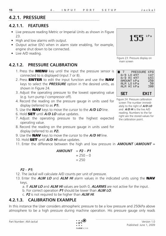
FEATuRES4.2.1.1. Live pressure reading Metric or Imperial Units as shown in Figure •23.High and low alarms with output.•Output active (0V) when in alarm state enabling, for example, •engine shut down to be connected.Live A/D reading.•
PRESSuRE CALIbRATION4.2.1.2. Press the 1. MEnU key until the input the pressure sensor is connected to is displayed (input 7 or 8).Press 2. EnTER to edit the input function and use the nAV keys to select the PRESSuRE option in the desired units, as shown in Figure 24.Adjust the operating pressure to the lowest operating value 3. (e.g. turn pump / compressor off).Record the reading on the pressure gauge in units used for 4. display (referred to as P1).Use the 5. nAV keys to move the cursor to the A/D LO line.Hold 6. SET until A/D LO value updates.Adjust the operating pressure to the highest expected 7. operating value.Record the reading on the pressure gauge in units used for 8. display (referred to as P2).Use the 9. nAV keys to move the cursor to the A/D hI line.Hold 10. SET until A/D hI value updates.Enter the difference between the high and low pressure in 11. AMOuNT (AMOuNT =
P2 – P1)The Jackal will calculate A/D counts per unit of pressure.12. Enter the 13. ALM LO and ALM hI alarm values in the indicated units using the nAV
keys.If a. ALM LO and ALM hI values are both 0, ALARMS are not active for the input.For correct operation b. P1 should be lower than ALM LO.P2c. is not required to be higher than ALM hI.
CALIbRATION ExAMPLE4.2.1.3. In this instance the User considers atmospheric pressure to be a low pressure and 250kPa above atmosphere to be a high pressure during machine operation. His pressure gauge only reads
Pressure calibration Figure 24: screen The number immedi-ately to the right of A/D LO and A/D hI is the live A/D reading. Numbers to the far right are the stored values for the calibration point.
AMOuNT = P2 – P1= 250 – 0= 250
Pressure display on Figure 23: main screen

J a c k a l
Part Number: AM-Jackal
16
Version 1.0Published: June 1, 2009
4 . I N P u T P O R T S E T u P
pressure above atmospheric, and therefore is a relative pressure, not absolute.
The user turned off the pump/compressor and vented the system applied to both the 1. pressure sensor and an independent gauge to atmospheric pressure.After allowing the A/D value to stabilize at atmospheric pressure, 2. P1, had a A/D value of 147. The User held the SET softkey until the A/D LO Value updated (147 displayed far right of A/D LO line, as shown in figure 24). The user turned on the pump/compressor and adjusted the pressure applied to both the 3. pressure sensor and an independent Gauge to 250kPa.After allowing the A/D value to stabilize at the high pressure, 4. P2, had a A/D value of 653.The User held the SET softkey until the A/D hI Value on the far right of the screen updated, as shown in Figure 20.The user then calculated the 5. AMOuNT:The 6. AMOuNT (250) was entered using the nAV keys.The User then entered high and low 7. ALARM points of 300kPa and 50kPa respectively
using the nAV keys.NOTES:
High and Low pressures used for calibration should be representative of highest and 1. lowest pressures expected during operation.The 2. A/D LO value used for calibration defines what the Jackal considers 0. Therefore the low pressure point used for calibration MuST be lower than any pressures expected in operation.Maximum values are determined by which ever is lowest of either the voltage input limit 3. (5V), or the sensor output limit. The Jackal does not calculate an offset for the sensor. Therefore if the lowest pressure 4. measured by the sensor is 1 Atmosphere (14.7 PSI, 101 kPa) the absolute pressure measurement will be e.g. 1 Atmosphere + Jackal reading, i.e. if the Jackal is reading 50kPa the absolute pressure is 100 + 50 = 150kPa.Accuracy of calibration is proportional to the difference of pressures used for calibration, 5.
Output of A/D with a change in pressure, indicating the assumed linear change in A/D value with change in pres-Figure 25: sure. NOTE: Values used in this graph do not relate to any specific pressure sensor and is only intended to illustrate the calibration process in the example provided.
P1
P2
Pressure (kPa)
A/D
Val
ue
200
600
1000
800
400
0 100 200 300

J a c k a l
Part Number: AM-Jackal
17
Version 1.0Published: June 1, 2009
4 . I N P u T P O R T S E T u P
i.e. a large pressure difference between P1 and P2 will provide a more accurate calibration.The Jackal assumes that the Pressure Sensor output changes linearly with a change in 6. pressure, as shown in Figure 21. In practice sensors may not be perfectly linear. It is recommended that pressure sensors used are operated in the linear region of sensor output.The maximum possible A/D counts are 1023. If the maximum expected pressure reading 7. is greater than 95% (~970 counts) of this value consider changing your pressure sensor. Alarms set at or above the 95% level may not operate reliably due to being in the ‘non-linear’ region of pressure sensor operation.
DEPTh4.2.2.
FEATuRES.4.2.2.1. Imperial or metric units as shown in Figure 26.•High and low alarms with output•Output active when in alarm state•Live A/D reading•
DEPTh CALIbRATION4.2.2.2. Press the 1. MEnU key until the input the depth sensor is connected to is displayed (input 7 or 8).Press 2. EnTER to edit the input function and use the nAV keys to select the DEPTh option in the desired units, as shown in Figure 27.When the implement is on flat ground, adjust the depth of 3. the tynes or plow to zero depth, e.g.. resting on the ground.Use the 4. nAV keys to move the cursor to the A/D LO line.Hold 5. SET until A/D LO value updates. This sets the point which the Jackal considers depth to be 0.Still on level ground, adjust the implement to a deep value.6. Use the 7. nAV keys to move the cursor to the A/D hI line.Hold 8. SET until A/D hI value updates.Dig a hole next to the plow or tyne and measure the distance from the surface of the soil 9. to the lowest point of the plow or tyne in the units used for display.Enter the depth measured in the previous step in 10. AMOuNT.The Jackal will calculate the A/D counts per unit of depth.11. Enter the 12. ALM LO and ALM hI alarm values using the nAV keys.
If a. ALM LO and ALM hI values are both 0, alarms are not active for the input.For correct operation b. D1 should be lower than ALM LO but D2 does not need to be higher than ALM hI as the Jackal will extrapolate.
CALIbRATION ExAMPLE4.2.2.3.
In this instance the User considers 27cm to be deep during machine operation.
Depth Main ScreenFigure 26:
Depth calibration Figure 27: screen. The number immedi-ately to the right of A/D LO and A/D hI is the live A/D reading. Numbers to the far right are the stored values for the calibration point.

J a c k a l
Part Number: AM-Jackal
18
Version 1.0Published: June 1, 2009
4 . I N P u T P O R T S E T u P
When on flat ground the user adjusted the tynes such that they were resting on the 1. ground.After allowing the A/D value to stabilize giving a value of 236. The User held the 2. SET softkey until the A/D LO Value updated (236 displayed on far right as in Figure 23). The user adjusted the tyne depth to what they consider deep, and after digging around a 3. tyne the ground level to the bottom of the tyne was measured as 27cm.After allowing the A/D value to stabilize at the deep value the A/D had a value of 894, as 4. shown in Figure 27. The User held the SET softkey until the A/D hI Value updated (far right of screen, as shown in Figure 23).
The user then entered 27 in the 5. AMOuNT setting using the nAV keys.NOTES:
High and Low depths used should be representative of highest and lowest depths 1. expected during operation.The 2. A/D LO value used for calibration defines what the Jackal considers 0. Therefore all alarm points MuST have a higher A/D value than the A/D LO value used in calibration.Maximum values are determined by which ever is lowest of either the voltage input limit 3. (5V), or the sensor output limit.Accuracy of calibration is proportional to the difference of depths used for calibration, 4. i.e. a large depth difference between A/D LO and A/D hI will provide a more accurate calibration than a small difference.The Jackal assumes that the potentiometer output changes linearly with a change 5. in depth, as shown in Figure 24. In practice sensors may not be perfectly linear. It is recommended that depth sensors used are operated in the linear region of sensor output.The maximum possible A/D counts are 1023. If the maximum expected depth reading 6.
Output of A/D with a change in depth, indicating the assumed linear change in A/D value with change in depth. Figure 28: The values used in this graph do not relate to any specific depth sensor and is only intended to illustrate the calibration process.
Depth (cm)
A/D
Val
ue
200
600
1000
800
400
10 20 30 40
D1
D2
J a c k a l
Part Number: AM-Jackal
19
Version 1.0Published: June 1, 2009
4 . I N P u T P O R T S E T u P
is greater than 95% (~970 counts) of this value consider changing your depth sensor. Alarms set at or above the 95% level may not operate reliably due to being in the ‘non-linear’ region of depth sensor or A/D operation.
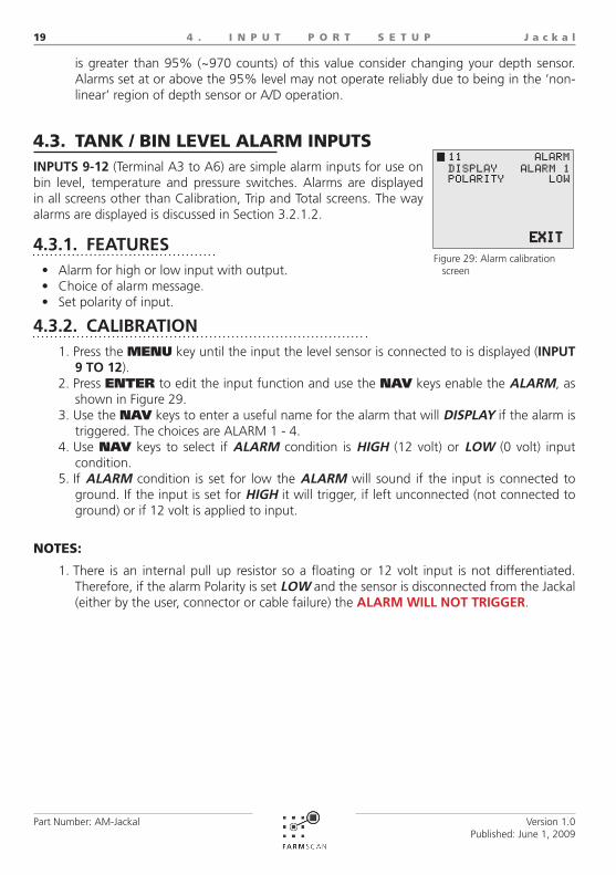
TANk / BIN LEvEL ALARM INPuTS4.3. INPuTS 9-12 (Terminal A3 to A6) are simple alarm inputs for use on bin level, temperature and pressure switches. Alarms are displayed in all screens other than Calibration, Trip and Total screens. The way alarms are displayed is discussed in Section 3.2.1.2.
FEATuRES4.3.1. Alarm for high or low input with output.•Choice of alarm message.•Set polarity of input.•
CALIbRATION4.3.2. Press the 1. MEnU key until the input the level sensor is connected to is displayed (INPuT 9 TO 12).Press 2. EnTER to edit the input function and use the nAV keys enable the ALARM, as shown in Figure 29.Use the 3. nAV keys to enter a useful name for the alarm that will DISPLAY if the alarm is triggered. The choices are ALARM 1 - 4.Use 4. nAV keys to select if ALARM condition is hIGh (12 volt) or LOW (0 volt) input condition.If 5. ALARM condition is set for low the ALARM will sound if the input is connected to ground. If the input is set for hIGh it will trigger, if left unconnected (not connected to ground) or if 12 volt is applied to input.
NOTES:
There is an internal pull up resistor so a floating or 12 volt input is not differentiated. 1. Therefore, if the alarm Polarity is set LOW and the sensor is disconnected from the Jackal (either by the user, connector or cable failure) the ALARM WILL NOT TRIGGER.
Alarm calibration Figure 29: screen

J a c k a l
Part Number: AM-Jackal
20
Version 1.0Published: June 1, 2009
4 . I N P u T P O R T S E T u P
RuN hOLD INPuT4.4. Input 13 (Terminal A2) is remote RUn/HoLD input.
FEATuRES4.4.1. Activate for high or low input.•Can be connected to machine signals to automate • RuN/hOLD mode change.
CALIbRATION4.4.2. Press the 1. MEnU key until the external run/hold, INPuT 13, is displayed.Press 2. EnTER to edit the input function and use the nAV keys enable in Figure 30. Enabling the external Run/Hold disabled the RUn/HoLD key on the jackal keypad.Use 3. nAV keys to select if hold condition is hIGh (12V) or LOW (Ground / 0V) input condition.
If set for • LOW polarity, the monitor will be in RuN mode when the input is LOW. If set for • hIGh the monitor will be in RuN mode when input is hIGh.Floating or disconnected inputs to • RuN/hOLD are registered as hIGh (12V).
NOTES:
When external 1. RUn/HoLD is enabled, the RUn/HoLD key is disabledThere is an internal pull up resistor so 2. FLOATING (NO CONNECTION) OR 12V INPuT IS NOT DIFFERENTIATED. Therefore, if the External RUn/HoLD input Polarity is set LOW and the sensor or external switch is disconnected from the Jackal (either by the user or via connector or cable failure) the jackal will remain in RUN mode irrespective of a change in machinery or switch state.
External RUN/HOLD Figure 30: calibration screen
!WARNING
When external RUn/HoLD is enabled, the RUn/HoLD key is disabled.

J a c k a l
Part Number: AM-Jackal
21
Version 1.0Published: June 1, 2009
5 . E X A M P L E C O N f I G u R A T I O N S
EXAMPLE CONfIGuRATIONS5.
All of the example configurations assume all inputs are initially in-active. The main screen should display as shown in Figure 31 and each input will display ‘NOT USED’ when cycled through using the MEnU key. If the Jackal does not display as shown in Figure 31, use the MEnU and nAV keys to inactivate inputs.
AREA METER5.1. To configure the Jackal as an area meter only a SPEED input is re-quired.
SPEED monitoring can be used in conjunction with shaft RPM moni-toring, RATE information, bin / tank level ALARMS and PRESSuRE or DEPTh monitoring.
SETuP PROCEDuRE5.1.1. Set up the desired 1. SPEED sensor.
If using a GPS input ensure • WhEEL is set to zero and the GPS baud rate is correct, as described in section 4.1.1.2.If using a wheel sensor, ensure it is correctly installed, as described in Figure 33.•
Setup a 2. SPEED input as defined in section 4.1.1.Exit input configuration using the 3. EXIT softkey or cycling through all inputs using the MEnU key.Main screen should display as 4. described in Figure 32.Pressing 5. RUn/HoLD will stop the accumulation of TOTALs but will continue live SPEED information readout.
Main screen when no Figure 31: inputs are configured
Example of main Figure 32: screen when configured as an Area Meter
Example of a correct wheel magnet sensor installation. Sen-Figure 33: sor appearence may differ depending on purchased model.
WHEELMAGNET
REED TYPESENSOR
5 - 10mmCLEARENCE
SENSOR - MAGNET

J a c k a l
Part Number: AM-Jackal
22
Version 1.0Published: June 1, 2009
5 . E X A M P L E C O N f I G u R A T I O N S
TAChO METER5.2. The Jackal can monitor up to 6 shafts, displayed as shown in Figure 29. Shaft RPM is displayed in order of input number.
RPM monitoring can be used in conjunction with SPEED monitor-ing, RATE information, bin / tank level ALARMS and PRESSuRE or DEPTh monitoring.
SETuP PROCEDuRE5.2.1. Ensure shaft sensors and magnets are installed correctly. 1. Examples of correct installation are shown in Figure 35.Setup a 2. RPM input as defined in section 4.1.2.
Ensure that coil sensors are attached to input 1.a. Repeat setup procedure as defined in section 4.1.2 until the required number of shaft 3. RPM inputs are configured.Exit input configuration using the 4. EXIT softkey or cycling through all inputs using the MEnU key.Main screen should display as described in Figure 34.5. If more than two shafts are monitored use 6. MoDE key to cycle through shaft RPM displays.
Example of main Figure 34: screen when configured as an Tacho Meter monitoring 2 shaft speeds
Example installations of shaft sensors. Ap-Figure 35: pearence of sensor will depend on specific model purchased.
SENSOR
AA-117SHAFT
MAGNET
BUTTONMAGNET
SENSOR
5 - 10mmCLEARENCE
SENSOR - MAGNET

J a c k a l
Part Number: AM-Jackal
23
Version 1.0Published: June 1, 2009
5 . E X A M P L E C O N f I G u R A T I O N S
fLOw METER5.3. The Jackal can be configured to monitor application rates of solid and liquid product, using a RATE input. If only one input is used the main screen will display as shown in Figure 36. The flow in-formation can be displayed as L/min (or Gal/min), or, if also using SPEED and implement WIDTh information the Jackal can calcu-late L/Ha (or Gal/Ac).
Flow monitoring can be used in conjunction with shaft RPM moni-toring, SPEED information, bin / tank level ALARMS and PRES-SuRE or DEPTh monitoring.
SETuP PROCEDuRE5.3.1. Setup a 1. RATE input as defined in section 4.1.4.
If using a ‘Coil’ sensor ensure that input 1 is used as the a. RATE input as discussed in section 4.1.4.
Setup a 2. SPEED input as defined in section 4.1.1Exit input configuration using the 3. EXIT softkey or cycling through all inputs using the MEnU key.When operating, main screen should display as described in Figure 36.4.
BATCh METER5.4. When configured as a Batch Meter, as shown in Figure 37, the Jackal uses a flow sensor and solenoid valve to accurately meter liquid vol-umes. The output of the Jackal (Terminal B8 and B9) is suitable for direct connection to a 12 volt solenoid valve.
SETuP PROCEDuRE5.4.1. Main screen should display as shown in Figure 37. If anything 1. else is displayed on the main screen, use the MEnU and nAV keys inactivate all inputs (‘NOT USED’ displayed).Calibrate the 2. bATCh input as defined in section 4.1.3. Exit input configuration using the EXIT softkey or cycling through all inputs using the MEnU key.After the flow meter used has been calibrated use the 3. MEnU key to reenter the calibration screen. AMOuNT4. now functions as the bATCh volume. Enter the desired amount using the nAV keys.Main screen should display as shown in Figure 37 if the batch 5. AMOuNT was 50L and Jackal is in hOLD mode (solenoid not activated).Press 6. RUn/HoLD to initiate batch. Batch amount should count down to zero.When the batch amount approaches zero the Jackal will deactivate the solenoid output 7.
Example of main Figure 36: screen when configured as a Flow Meter
Example of main Figure 37: screen when configured as an Batch Meter
Example of Batch Figure 38: main screen when an overrun of 0.5L has occured

J a c k a l
Part Number: AM-Jackal
24
Version 1.0Published: June 1, 2009
5 . E X A M P L E C O N f I G u R A T I O N S
to stop the batch. Any excess to the batch AMOuNT is recorded in LTS OVER (GAL OVER) as shown in figure 38. Press and hold oVER until the Jackal beeps to update the compensation for valve turn off time.Using the 8. TRIP key, ten different series of batches can be separately totaled.
AIRSEEDER SuRvEILLANCE MONITOR5.5. Two bin airseeders are a common unmonitored airseeder configura-tion. An example setup for such an airseeder is:
1 • SPEED input 2 bin level • ALARMS1 Fan • RPM (coil sensor)1 Air • PRESSuRE2 metering shaft • RATEs
It is recommended that the user purchase a Farmscan Junction Box 2202 to minimise ease the connection requirements and minimise wiring confusion.
SETuP PROCEDuRE5.5.1. Ensure no inputs are active by cycling through all inputs using the 1. MEnU key. All inputs must display ‘NOT USED’.Decide on which sensors will be connected to which input. 2.
The input is important for both the type of sensor and the order of display. In this a. example the fan shaft RPM sensor must connected to INPuT 1, as it is a coil sensor. Therefore the fan RPM will always be displayed on the top line on the main screen. The user decides that they would like the second line of the main screen display
Example of main Figure 40: screen when configured as an Airseeder Surveillance Monitor
Example configuration of a Batch system using the Jackal.Figure 39:
+-
TANK
WATERSOURCE
FLOWMETER
SOLENOIDVALVE
12V BATTERY
JACKAL
PUMP

J a c k a l
Part Number: AM-Jackal
25
Version 1.0Published: June 1, 2009
5 . E X A M P L E C O N f I G u R A T I O N S
shaft SPEED and attaches the wheel sensor to INPuT 2. INPuTS 3 AND 4 are used for RATE information. The RATE information the user is concerned with is kg/Ha of seed and fertiliser and therefore the relevant RATE input type is selected. The PRESSuRE sensor is connected to INPuT 7. Bin level ALARM sensors are connected to INPuTS 9 AND 10 and appropriate DISPLAY names are entered (“ALARM 1” and “ALARM 2”). As alarms are only displayed when triggered, and are displayed on all operational screens (i.e. not input calibration, trip, total and system menu screens) their order of connection does not affect display of other information.
Setup fan 3. RPM in input 1, as described in section 4.1.2.Setup metering shaft 4. RATE monitoring in inputs 3 and 4, as described in section 4.1.2.Setup Tank level 5. ALARMS, as described in section 4.3.Setup Fan air 6. PRESSuRE sensor, as described in section 4.2.1 (requires extra air pressure gauge to calibrate).Calibrate the 7. SPEED input (either WhEEL or GPS) as defined in section 4.1.1 (requires driving a known distance).
SPEED• input is calibrated last as all other inputs can be configured while the vehicle is stationary.
Exit input configuration using the 8. EXIT softkey or cycling through all inputs using the MEnU key.Main screen should display as described in Figure 40.9. Cycle through the information using the 10. MoDE key. The series of screens should
display as described below in Figure 41.An example of 11. TOTALs, TRIP 1 and TRIP 2 (current) for the described Airseeder
configuration is shown in Figure 38.Pressing 12. RUn/HoLD will stop the accumulation of TOTALs but will continue live
information readout.
Example of main screen and secondary information screens as the Figure 41: MoDE button is pressed when configured as an Airseeder monitor as described in this section
Example of the Figure 42: ToTAL (A), TRIP 1 (B) and TRIP 2 (C) (currently active trip, indicated by the X) screens for the Example Airseeder configuration
B CA

J a c k a l
Part Number: AM-Jackal
26
Version 1.0Published: June 1, 2009
6 . S E N S O R I N S T A L L A T I O N
SENSOR INSTALLATION6. Most Farmscan sensor wires have a common color code system:
Some sensors such as wheel sensors and shaft sensors only have two wires (signal and ground/earth). Other sensors that require +12 volts as well as signal and ground/earth will have 3 wires, such as flow sensors, bin level sensors and pressure sensors. All connections to the Jackal are provided via two 11 way terminals. The terminals are described in section 2.4.
SENSOR COMPATIBILITy ChART6.1.
WHITE SIGNAL
BLACK GROUND/EARTH (COMMON)
RED + 12V SUPPLY
SensorOptions 1007P
1009P
1010
1501
2034
2076
2077
2202
A-2220P
A-2080P
AA
-2009P
AA
-122P
AA
-1 25
AA
-242
AA
-230
AA
-210
AA
-232
AA
-231
Name TerminalInputs
1 B1 • • • • • • • • • • • •
2 – 6 B2 – B6 • • • • • • • • •
7 – 8 A7 & B7 •
9 – 12 A3 – A6 • •
Output1 B8 •

J a c k a l
Part Number: AM-Jackal
27
Version 1.0Published: June 1, 2009
6 . S E N S O R I N S T A L L A T I O N
COMPATIBLE SENSOR kITS6.2. There are a range of separate sensor kits available for the Jackal. Below is a list and brief descrip-tion of these kits.
Part # Description kit PartsPossible
additional parts
Compatible Inputs
1007P Wheel sensor kitAA-110P x 1AA-133 x 1
AC-200AC-205
Input 1-6 (B1-B6)
2002 Wheel sensor kitInput 1-6 (B1-B6)
1009P Tail shaft sensor kit (Slow speed 1-1500 RPM)AA-423 x 1AA-110P x 1
Input 1-6 (B1-B6)
1010Tail shaft sensor kit (High speed 100-9999
RPM)AA-423 x 1AA-112P x 1
Input 1 (B1)
1501 Solenoid Shutdown KitAH-488 x 1AC-208 x 1
M/F Packard’s
Output 1 (B8)
2034 Pulley Sensor kit (High speed 100-9999 RPM)AA-105 x 1AA-112P x 1
Input 1 (B1)
2076 Shaft sensor kit (Slow speed 1-1500 RPM)AA-117 x 1AA-110P x 1
Input 1-6 (B1-B6)
2077 Shaft sensor kit (High speed 100-9999 RPM)AA-117 x 1AA-112P x 1
Input 1 (B1)
2202 Remote junction box kit
A-2060 Bin/Tank level sensor kitA-2220PAC-300
AC-300AC-305
Input 9-12(A6-A3)
A-2080 Airflow pressure sensorA-2030AC-300
Input 7-8(A7&B7)
AA-2008P Proximity sensor kit - Blue
Input 1-6 (B1-B6)
AA-2009P Proximity sensor kit - Brown
AA-122P 2-90 l/min 1’ Flow meter
AA-125 1-18 l/min Flow meter
AA-242 2.5-75 l/min Flow meter
AA-230 10-100 l/min 1’ Rapid check Flow meter
AA-232 35-350 l/min 1 ½’ Rapid check Flow meter
AA-210 35-350 l/min 1 ½’ Coil flow sensor Input 1 (B1)AA-231 75-750 l/min 2’ Coil flow sensor

J a c k a l
Part Number: AM-Jackal
28
Version 1.0Published: June 1, 2009
6 . S E N S O R I N S T A L L A T I O N
INSTALLING SENSOR kITS6.3.
TWO WIRE ‘REED’ SENSOR kITS 6.3.1. This section applies to the following sensor kits:
1007P, 1009P, 2076These kits will all include a ‘reed’ type sensor. The reed type sensor is a 2 wire sensor and only uses a ground/earth wire and a signal wire. Fig-ure 43 shows which terminals to connect your sensors to. If the ground/earth (A1) terminal al-ready has a wire from another sensor applied to it then you will need to piggy back onto this wire. If the signal port has wires from another sensor applied to it then move to one of the ports shown that is free.
See Section 4 for how to setup an input and calibrate a sensor once installed.
NOTE:
If you are intending to use a ‘Coil’ sensor do not use port B11. DO NOT PIGGY bACk WhITE SIGNAL WIRES INTO SAME PORT2. .It is highly recommended that the ferrules, supplied with the Jackal kit, should be crimped 3. to bare wire ends. This minimises chance of any stray wires bridging.
ThREE WIRE ‘REED’ SENSOR kITS6.3.2. This section applies to the following sensor kits:
AA-2008P, AA-2009P, AA-122P, AA-125, AA-242, AA-230, AA-232
These kits will all include a ‘reed’ type ‘proxim-ity’ sensor. The proximity type sensor is a 3 wire sensor and use’s a ground/earth wire, a signal wire and a 12V power wire. Figure 44 is a pic-torial showing you where you can connect your sensors. If the ground/earth (A1) or regulated 12V power (OUT2, B9) terminal already has a wire from another sensor applied to it then you will need to piggy back onto this wire. If the signal port has wires from another sensor applied to it then move to one of the ports shown that is free.
See Section 4 for how to setup an input and calibrate a sensor once installed.
Jackal ports capable of accepting 3 wire ‘Reed’ Figure 44: sensor inputs. Black is GROuND, Red is POWER and white is SIGNAL. NOTE: do not use any other Ground or Power on the Jackal or vehicle for sensors
B1 B2 B3 B4 B5 B6 B7 B8 B9 B10 B11
A1 A2 A3 A4 A5 A6 A7 A8 A9 A10 A11
B1 B2 B3 B4 B5 B6 B7 B8 B9 B10 B11
A1 A2 A3 A4 A5 A6 A7 A8 A9 A10 A11
Jackal ports capable of accepting 2 wire ‘Reed’ Figure 43: sensor inputs. Black is GROuND and white is SIGNAL. NOTE: do not use any other Ground on the Jackal or vehi-cle for sensors.

J a c k a l
Part Number: AM-Jackal
29
Version 1.0Published: June 1, 2009
6 . S E N S O R I N S T A L L A T I O N
NOTES:
DO NOT PIGGY bACk WhITE SIGNAL WIRES INTO SAME PORT1. .It is also recommended that the ferrules supplied should be used to minimise chance of 2. any stray wires bridging.
TWO WIRE ‘COIL’ SENSOR kITS6.3.3. This section applies to the following sensor kits:
1010, 2034, 2077, AA-210, AA-231These kits will all include a ‘coil’ type sensor. The coil type sensor is a 2 wire sensor and only use’s a ground/earth wire and a signal wire. Figure 45 is a pictorial showing you where you can connect your sensors. If the ground/earth (A1) terminal already has a wire from another sensor applied to it then you will need to piggy back onto this wire. If the signal port has wires from another sensor applied to it then you will not be able to complete this application as there is only 1 coil port.
See Section 4 for how to setup an input and calibrate a sensor once installed.
NOTES:
DO NOT PIGGY bACk WhITE SIGNAL WIRES INTO SAME PORT1. .It is highly recommended that the ferrules supplied should be used to minimise chance 2. of any stray wires bridging. Bridging due to stray wires will cause false readings and can damage sensors.
ThREE WIRE ANALOG SENSOR kITS 6.3.4. This section applies to the following sensor kits:
A-2080These kits will include an analog sensor. The sensors use 3 wires sensor consisting of ground/earth wire, a signal wire and a 12V power wire. Figure 46 is a pictorial showing you where you can connect your sensors. If the ground/earth (A1) terminal or regulated 12V power (OUT2, B9) terminal already has a wire from another sensor applied to it then you will need to piggy back onto this wire. If the signal port has wires
B1 B2 B3 B4 B5 B6 B7 B8 B9 B10 B11
A1 A2 A3 A4 A5 A6 A7 A8 A9 A10 A11
Jackal ports capable of accepting analog sen-Figure 46: sor inputs. Black is GROuND, Red is POWER and white is SIGNAL. NOTE: do not use any other Ground or Power on the Jackal or vehicle for sensors
Jackal ports capable of accepting 2 wire ‘Coil’ Figure 45: sensor inputs. Black is GROuND and white is SIGNAL. NOTE: do not use any other Ground on the Jackal or ve-hicle for sensors
B1 B2 B3 B4 B5 B6 B7 B8 B9 B10 B11
A1 A2 A3 A4 A5 A6 A7 A8 A9 A10 A11

J a c k a l
Part Number: AM-Jackal
30
Version 1.0Published: June 1, 2009
6 . S E N S O R I N S T A L L A T I O N
from another sensor applied to it then move to one of the ports shown that is free.
See Section 4 for how to setup an input and calibrate a sensor once installed.
NOTES:
DO NOT PIGGY bACk WhITE SIGNAL WIRES INTO SAME PORT1. .It is highly recommended that the ferrules supplied should be used to minimise chance 2. of any stray wires bridging. Bridging due to stray wires will cause false readings and can damage sensors.
bIN / TANk LEVEL SENSOR kITS 6.3.5. This section applies to the following sensor kits:
A-2220PThese kits will include a Bin / Tank Level sen-sor. The sensors use 3 wires sensor consisting of ground/earth wire, a signal wire and a 12V power wire. Figure 47 is a pictorial showing you where you can connect your sensors. If the ground/earth (A1) terminal or regulated 12V power (OUT2, B9) already has a wire from an-other sensor applied to it then you will need to piggy back onto this wire. If the signal port has wires from another sensor applied to it then move to one of the ports shown that is free.
See Section 4 for how to setup an input and calibrate a sensor once installed.
NOTES:
DO NOT PIGGY bACk WhITE SIGNAL WIRES INTO SAME PORT1. .It is highly recommended that the ferrules supplied should be used to minimise chance 2. of any stray wires bridging. Bridging due to stray wires will cause false readings and can damage sensors.
REMOTE RuN/hOLD kIT6.3.6. This section applies to the following sensor kits:
A-xxxxFigure 48 is a pictorial showing you where you can connect the external RUn/HoLD switch. If the ground/earth (A1) terminal already has a wire from another sensor applied to it then you will need to piggy back onto this wire.
See Section 4 for how to setup and calibrate the switch operation once installed.
B1 B2 B3 B4 B5 B6 B7 B8 B9 B10 B11
A1 A2 A3 A4 A5 A6 A7 A8 A9 A10 A11
Jackal ports capable of accepting Bin / Tank Lev-Figure 47: el sensor inputs. Black is GROuND, Red is POWER and white is SIGNAL. NOTE: do not use any other Ground or Power on the Jackal or vehicle for sensors
Jackal ports capable of accepting remote Figure 48: RUn/HoLD input. Input shown for remote RUn/HoLD switch.Example of main screen when configured as an Area Meter
B1 B2 B3 B4 B5 B6 B7 B8 B9 B10 B11
A1 A2 A3 A4 A5 A6 A7 A8 A9 A10 A11

one monitor, many possibilitiesFARMSCAN jackal
B1 / 6 Tarlton Crescent | Perth Airport Western Australia 6105E: [email protected] W: www.farmscan.net.au
FARMSCAN is a registred Trademark of Computronics Corporation Ltd | ABN 58 009 089 025 | ASX : CPS