Faraday's Law Report Physics II Dr. Michael Zelin Thursday 2:00pm – 3:50pm Faraday’s Law by...
8
University Physics II Dr. Michael Zelin Thursday 2:00pm – 3:50pm Faraday’s Law by Group 9 Braden Reed Shawn Newton Sean-Michael Stubbs Lab Performed October 27, 2016 Report Submitted November 3, 2016
Transcript of Faraday's Law Report Physics II Dr. Michael Zelin Thursday 2:00pm – 3:50pm Faraday’s Law by...

University Physics II Dr. Michael Zelin
Thursday 2:00pm – 3:50pm
Faraday’s Law
by
Group 9 Braden Reed
Shawn Newton Sean-Michael Stubbs
Lab Performed October 27, 2016 Report Submitted November 3, 2016

Objective: To investigate Faraday’s Law, Lenz’s Law, and motion created by electrical current. Apparatus: Two Inductors, LabQuest Mini, Voltage Probe, Power Amplifier, Alligator Clips, Bar Magnet, Horseshoe Magnet, Iron Bar Introduction: Faraday’s Law of Induction states that the electromotive force is equal to the number of turns of wire, N, multiplied by the rate of change of magnetic flux through a single loop and is given by 𝜀 = −𝑁 !!!
!!. The flux is said to be positive from the north
pole of a magnet, and the direction of the current can be found using the right hand rule. During this lab, the change in voltage due to a magnetic field being brought close to an inductor will be observed. Lenz’s law and the relationship between frequency and Faraday’s law will also be investigated during this experiment. Experiment and Results: Part I: Faraday’s Law of Induction
For Part I of the lab, the LabQuest mini was plugged into the computer and a voltage probe was plugged into Channel 1 of the LabQuest. The voltage probe was then connected to an inductor using alligator clips. Logger Pro was opened and adjusted such that the duration was two seconds and the sampling rate was 500 samples/second. After zeroing the probe, a sample was collected. During the sample, one end of the horseshoe magnet was brought to the inductor (without the iron bar inside it) and pulled away quickly. The results can be seen in Figure 1. This process was repeated with the iron bar in the inductor and the results are shown in Figure 2.
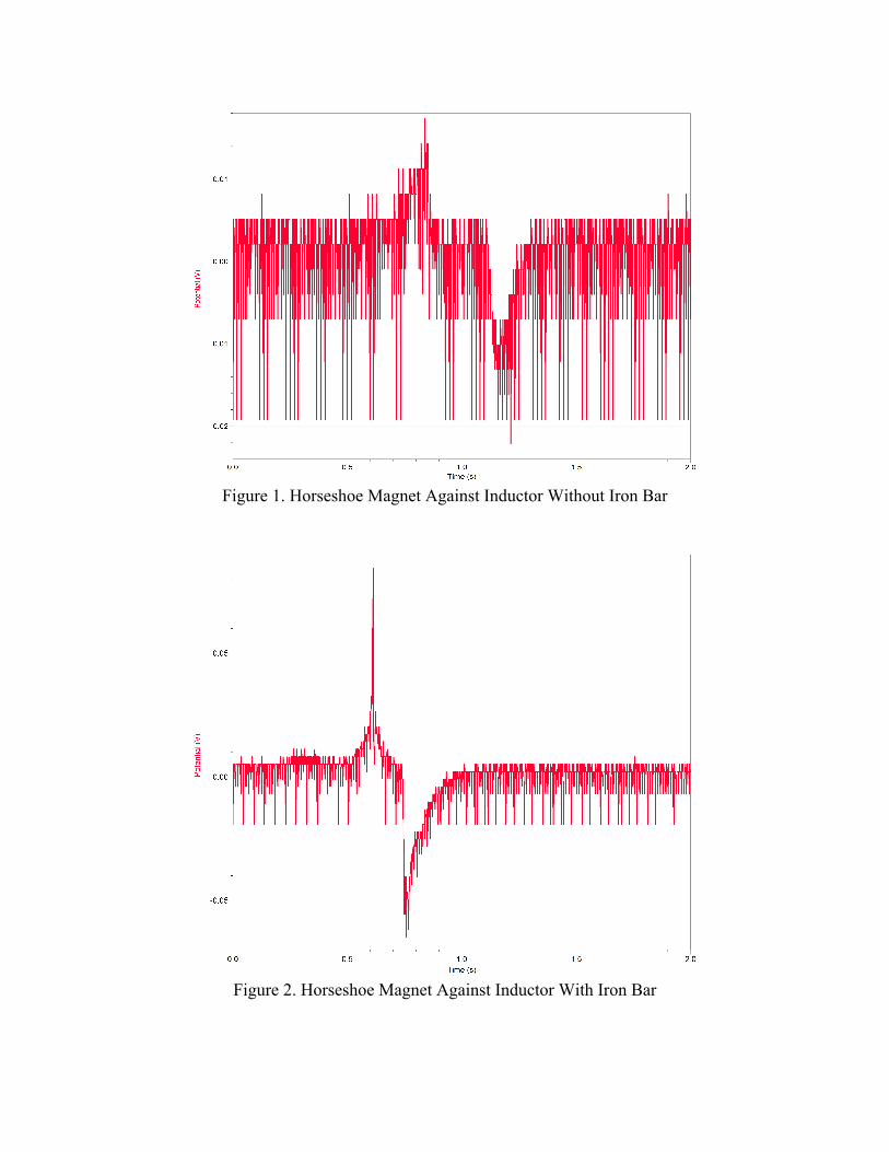
Figure 1. Horseshoe Magnet Against Inductor Without Iron Bar
Figure 2. Horseshoe Magnet Against Inductor With Iron Bar

Because the emf voltage started with a maximum (positive), it can be induced that the magnetic pole that was used was the south pole. This is because the flux from a south pole is taken to be negative, which would make the emf positive when plugged into Faraday’s Law equation. If this is true, the inductor is wound with the wire direction as shown in Figure 3. When the iron bar was included, the coil experienced a much higher potential. This tells us that the iron bar increased the magnitude of the magnetic field within the coil, which, in turn, increased the amount of voltage generated.
Figure 3. Inductor Wire Direction Diagram
Part II: Lenz’s Law Lenz’s law states that an induced electromotive force gives rise to a current whose magnetic field opposes the original change in magnetic flux. To test this, an iron bar was inserted into the inductor that was used in Part I. The horseshoe magnet was brought flush against the inductor and jerked quickly away while the sample was collected. The resulting graph was integrated. The procedure was repeated without the iron bar. Figures 4 and 5 are another example of how the iron bar significantly increases the magnetic field felt by the coil, therefore increasing the voltage. In Figure 4, the integral equals 0.003522 s*V, which is much greater than the 0.001053 s*V in Figure 5.

Figure 4. Lenz’s Law With Iron Bar
Figure 5. Lenz’s Law Without Iron Bar

Part III: Relating Frequency to Faraday’s Law For Part II of the experiment, the power amplifier was plugged in and adjusted such that the frequency was 1000 Hz. The second inductor was connected to the power amplifier, and the current monitor was connected to the LabQuest mini. The duration of the sample was changed to 0.01 seconds at 10,000 samples per second. The two inductors were then set side by side so that they were touching and the data was collected. This process was repeated with the inductors half an inch from each other, and again with the inductors an inch from each other. The results can be seen in the figures below. The results show that the magnetic field is the strongest when the inductors are touching, but gets weaker as the distance increases.
Figure 6. Part III Setup

Figure 7. Current Through Two
Inductors
Figure 8. Potential of Two Inductors
Touching
Figure 9. Potential of Two Inductors
Half an Inch Apart
Figure 10. Potential of Two Inductors One Inch Apart

Part IV: Motors For this part, the inductor with the iron bar was held in a hand with one base against the palm and fingers pressed against the other base. The amplifier was set to 1 Hz and 10 V. When the amplifier program was started, you could feel the iron bar inside the inductor start shaking and vibrating back and forth. The inductor was then laid on its side, with the end of the iron bar flush against one end of the inductor. When we did this, the iron bar was pulled towards the middle of the inductor. To see this in action, visit https://www.youtube.com/watch?v=28oO2khMHTk. Based on these results, it is feasible to use electrical current to create motion. As a matter of fact, the electric motor created in this lab experiment is used on a much larger scale in the real world for applications such as industrial fans, blowers, pumps, appliances, and power tools. Conclusion: This experiment showed how a magnetic field can be manipulated to induce voltage in an inductor. The existence or absence of an iron bar in the inductor affected the induced emf. Another discovery was that distance and magnetic field magnitude are inversely proportional, which means that distance and emf are also inversely related. Finally, a small electric motor was created to demonstrate how electric current can be used to create motion.