«FanControl‑VAG» Technical Manual -...
12
www.TEC-electronics.ru/en/ www.TEC‑electronics.ru «FanControl‑VAG» Technical Manual
Transcript of «FanControl‑VAG» Technical Manual -...

www.TEC-electronics.ru/en/www.TEC‑electronics.ru
«FanControl‑VAG»
Technical Manual
2 www.TEC-electronics.ru/en/
◊ Unit purpose ������������������������������������������������������������������������������������������������������������������������������� 2Table 1. Unit port outputs assigning .......................................................................................... 3
◊ Unit control ��������������������������������������������������������������������������������������������������������������������������������� 3Unit activation/deactivation via external outputs logic ................................................................ 4Unit control via original vehicle button ...................................................................................... 4Unit controlling via the standard remote control ......................................................................... 4InterTime Programmable timer .............................................................................................. 4Additional unit features enhancing its application (CAN bus adapter features) .............................. 4Standalone heater operation modes and deactivation causes indication ....................................... 5
◊ Unit application in VW Touareg (2003‑2010) vehicle ����������������������������������������������������������������������������������������������� 5
Original standalone heater control ............................................................................................ 5Unit connection ....................................................................................................................... 5Accessory standalone heater control ......................................................................................... 6Unit connection ....................................................................................................................... 6
◊ Unit application in VW Passat B6, Passat CC, VW Golf 5, VW Jetta (2006‑), VW Golf Plus, VW Caddy (2004‑), VW Touran, VW Tiguan; Skoda Octavia 2, Skoda Superb (2009‑); Seat Altea (2004‑), Leon (2006‑) vehicles ��������������������������������������������������� 6
Accessory standalone heater control ......................................................................................... 6Unit connection ....................................................................................................................... 6Original heater control ............................................................................................................. 7Unit connection ....................................................................................................................... 7Unit application with 2010 version of Webasto original heater ..................................................... 8
◊ Unit application in VW Multivan T5 (2003‑2009), VW Multivan T5 (2010‑) and VW Amarok vehicles ������������������������������������������������������������������������������������� 8
Original standalone heater control ............................................................................................ 8Unit connection ....................................................................................................................... 8
◊ Unit application in Audi Q7 vehicle ��������������������������������������������������������������������������������������������� 8
Original standalone heater control ............................................................................................ 9Unit connection ....................................................................................................................... 9Table 2. Technical data and operation conditions ....................................................................... 9Table 3. Standard delivery kit .................................................................................................. 9
TEC‑6317‑17 Technical Manual for «FanControl‑VAG» module
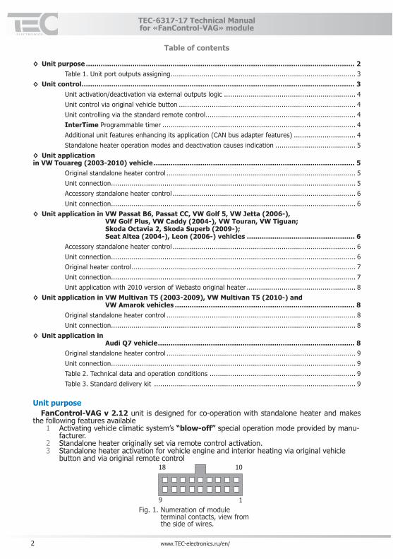
Unit purposeFanControl‑VAG v 2�12 unit is designed for co‑operation with standalone heater and makes
the following features available1 Activating vehicle climatic system’s “blow‑off” special operation mode provided by manu‑
facturer.2 Standalone heater originally set via remote control activation. 3 Standalone heater activation for vehicle engine and interior heating via original vehicle
button and via original remote control1018
9 1Fig. 1. Numeration of module
terminal contacts, view from the side of wires.
Table of contents

3www.TEC-electronics.ru/en/
TEC‑6317‑17 Technical Manual for «FanControl‑VAG» module
The unit has additional functional features:◊ On-the-flyprogrammed running time timer (from 10 to 120 min)◊ Heater deactivation when the car battery is low.◊ Standalone heater operation modes and deactivation causes indication.◊ Additional signals on unit’s digital outputs designed for cooperation with other systems
installed in the vehicle.◊ Standalone heater deactivation when the ignition is turned on and when the ignition key is
removed.
Table 1� Unit port outputs assigning
No Wire Color Assignment
1 Black Unit Ground2 Brown CAN‑L vehicle data bus (CAN 2)3 Brown CAN‑L vehicle data bus (CAN 1)4 Yellow Driver`s door (‑ output)5 Yellow/Blue All doors, hood and trunk (‑ output)6 Yellow/Green Security (‑ output)7 ‑ ‑8 Green Unit control external input (‑)9 Green/Black Unit control external input (‑)
10 Red +12V power supply11 Brown/Red CAN‑H vehicle data bus (CAN2) 12 Brown/Red CAN‑H vehicle data bus (CAN1)13 White/Red Accessory heater control (+) output14 Orange/Black LED indicator control (+) output15 Pink/Black Original alarm system panic (+ output)16 ‑ ‑17 Green/White Unit control external (+) input18 White/Blue Original heater control digital bus
Unit control
The unit can be controlled via the following means:◊ Original vehicle button (central locking system lock button on the driver`s door)◊ Original remote control◊ Accessory units via external outputs (GSM pager, accessory alarm system etc.)
4 www.TEC-electronics.ru/en/
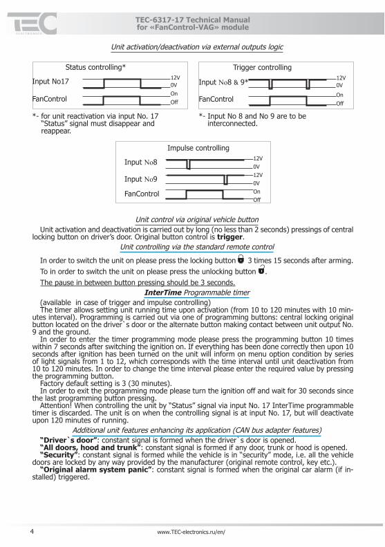
Unit activation/deactivation via external outputs logic
Status controlling*12V0VОnOff
Input No17
FanControl
*‑ for unit reactivation via input No. 17 “Status” signal must disappear and reappear.
Impulse controlling12V0V12V0VOnOff
Input No8
Input No9
FanControl
Trigger controlling12V0VInput No8 & 9*
FanControlOnOff
*‑ Input No 8 and No 9 are to be interconnected.
Unit control via original vehicle button
Unit activation and deactivation is carried out by long (no less than 2 seconds) pressings of central locking button on driver’s door. Original button control is trigger.
Unit controlling via the standard remote control
In order to switch the unit on please press the locking button 3 times 15 seconds after arming.To in order to switch the unit on please press the unlocking button .The pause in between button pressing should be 3 seconds.
InterTime Programmable timer(available in case of trigger and impulse controlling)The timer allows setting unit running time upon activation (from 10 to 120 minutes with 10 min‑
utes interval). Programming is carried out via one of programming buttons: central locking original button located on the driver`s door or the alternate button making contact between unit output No. 9 and the ground.
In order to enter the timer programming mode please press the programming button 10 times within 7 seconds after switching the ignition on. If everything has been done correctly then upon 10 seconds after ignition has been turned on the unit will inform on menu option condition by series of light signals from 1 to 12, which corresponds with the time interval until unit deactivation from 10 to 120 minutes. In order to change the time interval please enter the required value by pressing the programming button.
Factory default setting is 3 (30 minutes).In order to exit the programming mode please turn the ignition off and wait for 30 seconds since
the last programming button pressing.Attention! When controlling the unit by “Status” signal via input No. 17 InterTime programmable
timer is discarded. The unit is on when the controlling signal is at input No. 17, but will deactivate upon 120 minutes of running.
Additional unit features enhancing its application (CAN bus adapter features)“Driver`s door”: constant signal is formed when the driver`s door is opened.“All doors, hood and trunk”: constant signal is formed if any door, trunk or hood is opened.“Security”: constant signal is formed while the vehicle is in “security” mode, i.e. all the vehicle
doors are locked by any way provided by the manufacturer (original remote control, key etc.).“Original alarm system panic”: constant signal is formed when the original car alarm (if in‑
stalled) triggered.
TEC‑6317‑17 Technical Manual for «FanControl‑VAG» module

5www.TEC-electronics.ru/en/
TEC‑6317‑17 Technical Manual for «FanControl‑VAG» module
Standalone heater operation modes and deactivation causes indicationIndication is carried out by LED indicator. There are 4 LED operation modes:
1 LED is constantly on – the unit is operational.2 LED flashes once, then pause (only when the standard standalone heater is controlled)
– the unit has deactivated due to heater failure. Please check the fuel level. If there is suf‑ficient fuel (not less than ¼ of the tank) please contact the official Volkswagen representa‑tive.
3 LED flashes twice repeatedly, then pause – the unit has not activated due to low vehicle battery power.
4 Three repetitive flashes, then pause (only when controlling the original heater) – the unit has not activated due to heater failure. Please check the fuel level. If there is sufficient fuel (not less than ¼ of the tank) please contact the official Volkswagen representative.
Unit application in VW Touareg (2003‑2010) vehicle
Wire assignment:◊ CAN‑L – orange with brown stripe◊ CAN‑H – orange with green stripe.
Original standalone heater controlYou can find out whether the vehicle is equipped with original standalone heater from the sticker
located on the B‑pillar under the driver’s door.The unit allows turning the original standalone heater for engine and interior heating with ac‑
cessory units (GSM pager, accessory car alarm system etc.) via external outputs or with an original vehicle button (central locking button on the driver’s door).
Unit connectionThe unit is connected to the interior CAN‑bus in any preferable place, e.g. behind climate‑control
system control unit. (see Fig.2).
Fig. 2. When connecting, CAN1 and CAN2 wires of the unit are not used. The output No. 18 (original
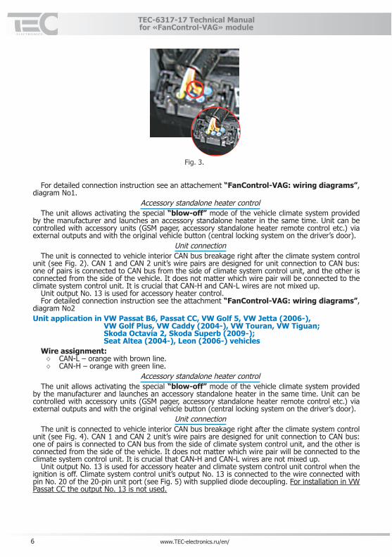
heater digital control bus) is connected to pin No. 1 of original standalone heater’s 6‑pin connection port (see Fig. 3) with terminal wire included into the delivery kit. Insert the terminal wire in the port. Connection is carried out in the rear niche of the front left wheel (see Fig. 3).
6 www.TEC-electronics.ru/en/
TEC‑6317‑17 Technical Manual for «FanControl‑VAG» module
Fig. 3.
For detailed connection instruction see an attachement “FanControl‑VAG: wiring diagrams”,
diagram No1.Accessory standalone heater control
The unit allows activating the special “blow‑off” mode of the vehicle climate system provided by the manufacturer and launches an accessory standalone heater in the same time. Unit can be controlled with accessory units (GSM pager, accessory standalone heater remote control etc.) via external outputs and with the original vehicle button (central locking system on the driver’s door).
Unit connectionThe unit is connected to vehicle interior CAN bus breakage right after the climate system control
unit (see Fig. 2). CAN 1 and CAN 2 unit’s wire pairs are designed for unit connection to CAN bus: one of pairs is connected to CAN bus from the side of climate system control unit, and the other is connected from the side of the vehicle. It does not matter which wire pair will be connected to the climate system control unit. It is crucial that CAN‑H and CAN‑L wires are not mixed up.
Unit output No. 13 is used for accessory heater control.For detailed connection instruction see the attachment “FanControl‑VAG: wiring diagrams”,
diagram No2Unit application in VW Passat B6, Passat CC, VW Golf 5, VW Jetta (2006‑),
VW Golf Plus, VW Caddy (2004‑), VW Touran, VW Tiguan; Skoda Octavia 2, Skoda Superb (2009‑); Seat Altea (2004‑), Leon (2006‑) vehicles
Wire assignment:◊ CAN‑L – orange with brown line.◊ CAN‑H – orange with green line.
Accessory standalone heater controlThe unit allows activating the special “blow‑off” mode of the vehicle climate system provided
by the manufacturer and launches an accessory standalone heater in the same time. Unit can be controlled with accessory units (GSM pager, accessory standalone heater remote control etc.) via external outputs and with the original vehicle button (central locking system on the driver’s door).
Unit connectionThe unit is connected to vehicle interior CAN bus breakage right after the climate system control
unit (see Fig. 4). CAN 1 and CAN 2 unit’s wire pairs are designed for unit connection to CAN bus: one of pairs is connected to CAN bus from the side of climate system control unit, and the other is connected from the side of the vehicle. It does not matter which wire pair will be connected to the climate system control unit. It is crucial that CAN‑H and CAN‑L wires are not mixed up.
Unit output No. 13 is used for accessory heater and climate system control unit control when the ignition is off. Climate system control unit’s output No. 13 is connected to the wire connected with pin No. 20 of the 20‑pin unit port (see Fig. 5) with supplied diode decoupling. For installation in VW Passat CC the output No. 13 is not used.

7www.TEC-electronics.ru/en/
TEC‑6317‑17 Technical Manual for «FanControl‑VAG» module
Fig. 4. Fig. 5. For detailed connection instruction please see an attachment “FanControl‑VAG: wiring dia‑
grams”, diagram No3.Original heater control
The unit allows turning the climate system on in the same mode in which it was prior to ignition’s activation and activate the standalone heater at the same time. Unit can be controlled with acces‑sory units (GSM pager, accessory standalone heater remote control etc.) via external outputs and with the original vehicle button (central locking system on the driver’s door).
Unit connectionThe unit is connected to vehicle interior CAN bus breakage right after the climate system control
unit (see Fig. 4). CAN 1 and CAN 2 unit’s wire pairs are designed for unit connection to CAN bus: one of pairs is connected to CAN bus from the side of climate system control unit, and the other is connected from the side of the vehicle. It does not matter which wire pair will be connected to the climate system control unit. It is crucial that CAN‑H and CAN‑L wires are not mixed up.
Unit output No. 13 is used for accessory heater and climate system control unit control when the ignition is off. Climate system control unit’s output No. 13 is connected to the wire connected with pin No. 20 of the 20‑pin unit port (see Fig. 5) with supplied diode decoupling.
The output No. 18 (original heater digital control bus) is connected to pin No. 2 of original stand‑alone heater’s 8‑pin connection port with terminal wire included into the delivery kit. Insert the terminal wire in the port (see Fig. 6). Connection is carried behind the bumper on the right‑hand side (it is recommended to remove the fog light for facilitating the installation.
Fig. 6. Connection is carried behind the bumper on the right‑hand side (it is recommended to remove the
fog light for facilitating the installation.For detailed connection instruction see an attachment “FanControl‑VAG: wiring diagrams”,
diagram No4.
8 www.TEC-electronics.ru/en/
TEC‑6317‑17 Technical Manual for «FanControl‑VAG» module
Unit application with 2010 version of Webasto original heaterIt is required to additionally install the module eFC‑VAG.eFC‑VAG unit works only in combination with FanControl‑VAG with version v 2.9 or later. If the
vehicle is equipped with older FanControl‑VAG version (older than v 2.9) it is to be replaced or manufacturer software is to be updated.
Installation of eFC‑VAG unit is required in following cases:◊ FanControl‑VAG is installed in the vehicle. After the visit to authorized VW dealer and We‑
basto software updating the climate system is activated via FanControl unit but the heater won’t start.
◊ When installing FanControl‑VAG unit. In order to guarantee the heater launching regard‑lessofWebastosoftwareversioninstalledbytheofficialVWdealer.
For the purposes of eFC‑VAG installation output No. 18 of FanControl‑VAG unit (standard heater control digital bus) connection is not required.Unit application in VW Multivan T5 (2003‑2009), VW Multivan T5 (2010‑) and
VW Amarok vehiclesWire assignment (twisted‑pair wire):◊ CAN‑L – orange with brown line◊ CAN‑H – orange with green line
Original standalone heater controlThe unit allows activating the original standalone heater for engine and interior heating with ac‑
cessory units (GSM pager, accessory standalone heater remote control etc.) The unit does not allow activating the standalone heater with the original vehicle button (central
locking system).Unit connection
The unit is connected to vehicle interior CAN bus in any area that would be convenient, e.g. to the wire harness under the driver’s seat, to the wire harness behind the climate system control unit, to the wire harness under the right rear seat. When connecting, CAN 1 wire pair is used while CAN 2 wire pair is not.
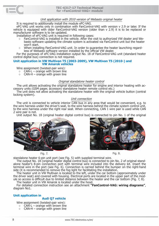
Unit output No. 18 (original heater digital control bus) is connected to pin No. 1 of the original
standalone heater 6‑pin unit port (see Fig. 5) with supplied terminal wire.Fig. 7. Fig. 8.
The output No. 18 (original heater digital control bus) is connected to pin No. 2 of original stand‑
alone heater’s 8‑pin connection port with terminal wire included into the delivery kit. Insert the terminal wire in the port (see Fig. 6). Connection is carried behind the bumper on the right‑hand side (it is recommended to remove the fog light for facilitating the installation.
The heater unit in VW Multivan is located to the left, under the car bottom (approximately under the driver seat) and covered with housing. Electrical ports are located in the upper part of the mod‑ule so access is difficult due to limited distance between the heater and the car bottom (Fig. 7, 8).
The heater unit in VW Amarok is located under the hood.For detailed connection instruction see an attachment “FanControl‑VAG: wiring diagrams”,
diagram No1.
Unit application in Audi Q7 vehicle
Wire assignment (twisted‑pair wire):◊ CAN‑L – orange with brown line◊ CAN‑H – orange with green line
9www.TEC-electronics.ru/en/
TEC‑6317‑17 Technical Manual for «FanControl‑VAG» module
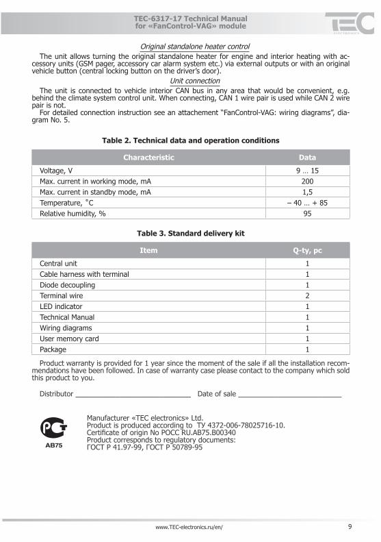
Original standalone heater controlThe unit allows turning the original standalone heater for engine and interior heating with ac‑
cessory units (GSM pager, accessory car alarm system etc.) via external outputs or with an original vehicle button (central locking button on the driver’s door).
Unit connectionThe unit is connected to vehicle interior CAN bus in any area that would be convenient, e.g.
behind the climate system control unit. When connecting, CAN 1 wire pair is used while CAN 2 wire pair is not.
For detailed connection instruction see an attachement “FanControl‑VAG: wiring diagrams”, dia‑gram No. 5.
Table 2� Technical data and operation conditions
Characteristic Data
Voltage, V 9 … 15Max. current in working mode, mA 200Max. current in standby mode, mA 1,5Temperature,˚C – 40 … + 85Relative humidity, % 95
Table 3� Standard delivery kit
Item Q‑ty, pc
Central unit 1Cable harness with terminal 1Diode decoupling 1Terminal wire 2LED indicator 1Technical Manual 1Wiring diagrams 1User memory card 1Package 1
Product warranty is provided for 1 year since the moment of the sale if all the installation recom‑
mendations have been followed. In case of warranty case please contact to the company which sold this product to you.
Distributor _____________________________ Date of sale __________________________
OManufacturer «TEC electronics» Ltd. Product is produced according toТУ4372-006-78025716-10. Certificate of origin NoРОССRU.AB75.B00340Product corresponds to regulatory documents: ГОСТР41.97-99,ГОСТР50789-95

10 www.TEC-electronics.ru/en/
TEC‑6317‑17 Technical Manual for «FanControl‑VAG» module

11www.TEC-electronics.ru/en/
TEC‑6317‑17 Technical Manual for «FanControl‑VAG» module

12 www.TEC-electronics.ru/en/
TEC‑6317‑17 Technical Manual for «FanControl‑VAG» module