
Fan Coil Units Technical Data -...
41
FWM-DT/DF ECDEN10-400 Technical Data Fan Coil Units
Transcript of Fan Coil Units Technical Data -...
FWM-DT/DF
E C D E N 1 0 - 4 0 0
Technical DataFan Coil Units
FWM-DT/DF
E C D E N 1 0 - 4 0 0
Technical DataFan Coil Units
• Fan coil • Indoor Unit 1
• Indoor Unit • Fan Coil Units • FWM-DT/DF
TABLE OF CONTENTSFWM-DT/DF
1 Features . . . . . . . . . . . . . . . . . . . . . . . . . . . . . . . . . . . . . . . . . . . . . . . . . . . . . . . . . . . . . 2
2 Specifications . . . . . . . . . . . . . . . . . . . . . . . . . . . . . . . . . . . . . . . . . . . . . . . . . . . . . . . 3Technical Specifications - 2-pipe . . . . . . . . . . . . . . . . . . . . . . . . . . . . . . . . . . . . . 3Technical Specifications - 4-pipe . . . . . . . . . . . . . . . . . . . . . . . . . . . . . . . . . . . . . 4Electrical Specifications 2-pipe and 4-pipe . . . . . . . . . . . . . . . . . . . . . . . . . . . 5
3 Options . . . . . . . . . . . . . . . . . . . . . . . . . . . . . . . . . . . . . . . . . . . . . . . . . . . . . . . . . . . . . . 6Options . . . . . . . . . . . . . . . . . . . . . . . . . . . . . . . . . . . . . . . . . . . . . . . . . . . . . . . . . . . . . . . 6
4 Control systems . . . . . . . . . . . . . . . . . . . . . . . . . . . . . . . . . . . . . . . . . . . . . . . . . . . . 7Control Systems . . . . . . . . . . . . . . . . . . . . . . . . . . . . . . . . . . . . . . . . . . . . . . . . . . . . . 7
5 Capacity tables . . . . . . . . . . . . . . . . . . . . . . . . . . . . . . . . . . . . . . . . . . . . . . . . . . . . . 8Cooling Capacity Tables - 2-pipe . . . . . . . . . . . . . . . . . . . . . . . . . . . . . . . . . . . . 8Cooling Capacity Tables - 4-pipe . . . . . . . . . . . . . . . . . . . . . . . . . . . . . . . . . . . 12Capacity Correction Factor . . . . . . . . . . . . . . . . . . . . . . . . . . . . . . . . . . . . . . . . . . 16Heating Capacity Tables - 2-pipe . . . . . . . . . . . . . . . . . . . . . . . . . . . . . . . . . . . 18Heating Capacity Tables - 4-pipe . . . . . . . . . . . . . . . . . . . . . . . . . . . . . . . . . . . 20Power consumption - 2-pipe . . . . . . . . . . . . . . . . . . . . . . . . . . . . . . . . . . . . . . . . 22Power consumption - 4-pipe . . . . . . . . . . . . . . . . . . . . . . . . . . . . . . . . . . . . . . . . 26
6 Dimensional drawings . . . . . . . . . . . . . . . . . . . . . . . . . . . . . . . . . . . . . . . . . . . . 30Dimensional Drawings . . . . . . . . . . . . . . . . . . . . . . . . . . . . . . . . . . . . . . . . . . . . . . 30
7 Wiring diagrams . . . . . . . . . . . . . . . . . . . . . . . . . . . . . . . . . . . . . . . . . . . . . . . . . . . 31Wiring Diagrams - Single Phase . . . . . . . . . . . . . . . . . . . . . . . . . . . . . . . . . . . 31
8 Sound data . . . . . . . . . . . . . . . . . . . . . . . . . . . . . . . . . . . . . . . . . . . . . . . . . . . . . . . . . 32Sound Level Data - 2-pipe . . . . . . . . . . . . . . . . . . . . . . . . . . . . . . . . . . . . . . . . . . 32Sound Level Data - 4-pipe . . . . . . . . . . . . . . . . . . . . . . . . . . . . . . . . . . . . . . . . . . 33
9 Installation . . . . . . . . . . . . . . . . . . . . . . . . . . . . . . . . . . . . . . . . . . . . . . . . . . . . . . . . . . 34Installation Method . . . . . . . . . . . . . . . . . . . . . . . . . . . . . . . . . . . . . . . . . . . . . . . . . . 34
10 Operation range . . . . . . . . . . . . . . . . . . . . . . . . . . . . . . . . . . . . . . . . . . . . . . . . . . . 36Operation Range . . . . . . . . . . . . . . . . . . . . . . . . . . . . . . . . . . . . . . . . . . . . . . . . . . . . 36
11 Hydraulic performance. . . . . . . . . . . . . . . . . . . . . . . . . . . . . . . . . . . . . . . . . . . . 37Water Pressure Drop Curve Evaporator - Cooling 2-pipe . . . . . . . . . . 37Water Pressure Drop Curve Evaporator - Heating 2-pipe . . . . . . . . . . 37Water Pressure Drop Curve Evaporator - Heating 4-pipe . . . . . . . . . . 38

• Indoor Unit • Fan Coil Units • FWM-DT/DF
• Fan coil • Indoor Unit2
1 Features
Indoor Unit Fan coil FWM-DT/DF Fan Coil Un • Quick fixing system for wall or ceiling mounted installation
• Pre-assembled 3-way/4-port on/off valves are available
• Valve packages are insulated, no extra drain pan required
• Valve packages contain balancing valves and sensor pocket
• Fast-on connections for electrical options: no tools needed
• The air filter can easily be removed for cleaning
• Fan coil • Indoor Unit 3
• Indoor Unit • Fan Coil Units • FWM-DT/DF
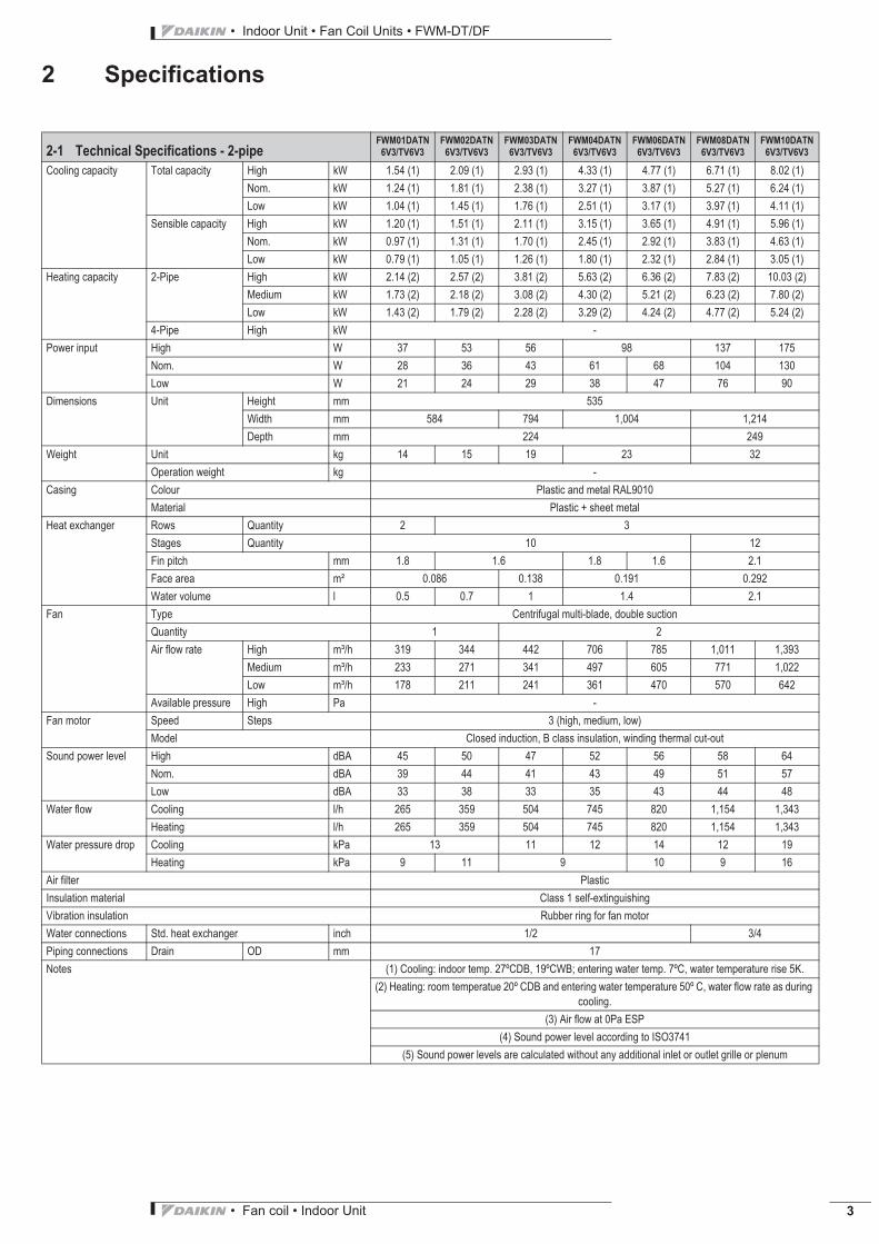
2 Specifications
2-1 Technical Specifications - 2-pipeFWM01DATN
6V3/TV6V3FWM02DATN
6V3/TV6V3FWM03DATN
6V3/TV6V3FWM04DATN
6V3/TV6V3FWM06DATN
6V3/TV6V3FWM08DATN
6V3/TV6V3FWM10DATN
6V3/TV6V3
Cooling capacity Total capacity High kW 1.54 (1) 2.09 (1) 2.93 (1) 4.33 (1) 4.77 (1) 6.71 (1) 8.02 (1)Nom. kW 1.24 (1) 1.81 (1) 2.38 (1) 3.27 (1) 3.87 (1) 5.27 (1) 6.24 (1)Low kW 1.04 (1) 1.45 (1) 1.76 (1) 2.51 (1) 3.17 (1) 3.97 (1) 4.11 (1)
Sensible capacity High kW 1.20 (1) 1.51 (1) 2.11 (1) 3.15 (1) 3.65 (1) 4.91 (1) 5.96 (1)Nom. kW 0.97 (1) 1.31 (1) 1.70 (1) 2.45 (1) 2.92 (1) 3.83 (1) 4.63 (1)Low kW 0.79 (1) 1.05 (1) 1.26 (1) 1.80 (1) 2.32 (1) 2.84 (1) 3.05 (1)
Heating capacity 2-Pipe High kW 2.14 (2) 2.57 (2) 3.81 (2) 5.63 (2) 6.36 (2) 7.83 (2) 10.03 (2)Medium kW 1.73 (2) 2.18 (2) 3.08 (2) 4.30 (2) 5.21 (2) 6.23 (2) 7.80 (2)Low kW 1.43 (2) 1.79 (2) 2.28 (2) 3.29 (2) 4.24 (2) 4.77 (2) 5.24 (2)
4-Pipe High kW -Power input High W 37 53 56 98 137 175
Nom. W 28 36 43 61 68 104 130Low W 21 24 29 38 47 76 90
Dimensions Unit Height mm 535Width mm 584 794 1,004 1,214Depth mm 224 249
Weight Unit kg 14 15 19 23 32Operation weight kg -
Casing Colour Plastic and metal RAL9010Material Plastic + sheet metal
Heat exchanger Rows Quantity 2 3Stages Quantity 10 12Fin pitch mm 1.8 1.6 1.8 1.6 2.1Face area m² 0.086 0.138 0.191 0.292Water volume l 0.5 0.7 1 1.4 2.1
Fan Type Centrifugal multi-blade, double suctionQuantity 1 2Air flow rate High m³/h 319 344 442 706 785 1,011 1,393
Medium m³/h 233 271 341 497 605 771 1,022Low m³/h 178 211 241 361 470 570 642
Available pressure High Pa -Fan motor Speed Steps 3 (high, medium, low)
Model Closed induction, B class insulation, winding thermal cut-outSound power level High dBA 45 50 47 52 56 58 64
Nom. dBA 39 44 41 43 49 51 57Low dBA 33 38 33 35 43 44 48
Water flow Cooling l/h 265 359 504 745 820 1,154 1,343Heating l/h 265 359 504 745 820 1,154 1,343
Water pressure drop Cooling kPa 13 11 12 14 12 19Heating kPa 9 11 9 10 9 16
Air filter PlasticInsulation material Class 1 self-extinguishingVibration insulation Rubber ring for fan motorWater connections Std. heat exchanger inch 1/2 3/4Piping connections Drain OD mm 17Notes (1) Cooling: indoor temp. 27ºCDB, 19ºCWB; entering water temp. 7ºC, water temperature rise 5K.
(2) Heating: room temperatue 20º CDB and entering water temperature 50º C, water flow rate as during cooling.
(3) Air flow at 0Pa ESP(4) Sound power level according to ISO3741
(5) Sound power levels are calculated without any additional inlet or outlet grille or plenum
• Indoor Unit • Fan Coil Units • FWM-DT/DF
• Fan coil • Indoor Unit4
2 Specifications
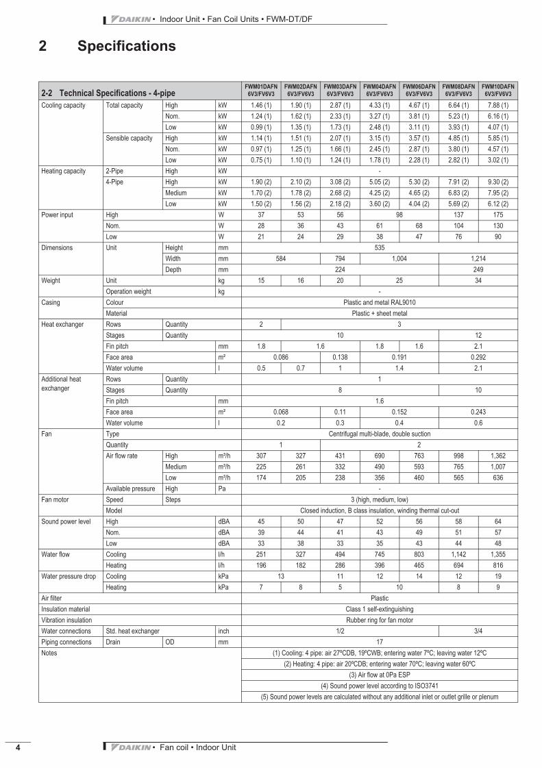
2-2 Technical Specifications - 4-pipeFWM01DAFN
6V3/FV6V3FWM02DAFN
6V3/FV6V3FWM03DAFN
6V3/FV6V3FWM04DAFN
6V3/FV6V3FWM06DAFN
6V3/FV6V3FWM08DAFN
6V3/FV6V3FWM10DAFN
6V3/FV6V3
Cooling capacity Total capacity High kW 1.46 (1) 1.90 (1) 2.87 (1) 4.33 (1) 4.67 (1) 6.64 (1) 7.88 (1)Nom. kW 1.24 (1) 1.62 (1) 2.33 (1) 3.27 (1) 3.81 (1) 5.23 (1) 6.16 (1)Low kW 0.99 (1) 1.35 (1) 1.73 (1) 2.48 (1) 3.11 (1) 3.93 (1) 4.07 (1)
Sensible capacity High kW 1.14 (1) 1.51 (1) 2.07 (1) 3.15 (1) 3.57 (1) 4.85 (1) 5.85 (1)Nom. kW 0.97 (1) 1.25 (1) 1.66 (1) 2.45 (1) 2.87 (1) 3.80 (1) 4.57 (1)Low kW 0.75 (1) 1.10 (1) 1.24 (1) 1.78 (1) 2.28 (1) 2.82 (1) 3.02 (1)
Heating capacity 2-Pipe High kW -4-Pipe High kW 1.90 (2) 2.10 (2) 3.08 (2) 5.05 (2) 5.30 (2) 7.91 (2) 9.30 (2)
Medium kW 1.70 (2) 1.78 (2) 2.68 (2) 4.25 (2) 4.65 (2) 6.83 (2) 7.95 (2)Low kW 1.50 (2) 1.56 (2) 2.18 (2) 3.60 (2) 4.04 (2) 5.69 (2) 6.12 (2)
Power input High W 37 53 56 98 137 175Nom. W 28 36 43 61 68 104 130Low W 21 24 29 38 47 76 90
Dimensions Unit Height mm 535Width mm 584 794 1,004 1,214Depth mm 224 249
Weight Unit kg 15 16 20 25 34Operation weight kg -
Casing Colour Plastic and metal RAL9010Material Plastic + sheet metal
Heat exchanger Rows Quantity 2 3Stages Quantity 10 12Fin pitch mm 1.8 1.6 1.8 1.6 2.1Face area m² 0.086 0.138 0.191 0.292Water volume l 0.5 0.7 1 1.4 2.1
Additional heat exchanger
Rows Quantity 1Stages Quantity 8 10Fin pitch mm 1.6Face area m² 0.068 0.11 0.152 0.243Water volume l 0.2 0.3 0.4 0.6
Fan Type Centrifugal multi-blade, double suctionQuantity 1 2Air flow rate High m³/h 307 327 431 690 763 998 1,362
Medium m³/h 225 261 332 490 593 765 1,007Low m³/h 174 205 238 356 460 565 636
Available pressure High Pa -Fan motor Speed Steps 3 (high, medium, low)
Model Closed induction, B class insulation, winding thermal cut-outSound power level High dBA 45 50 47 52 56 58 64
Nom. dBA 39 44 41 43 49 51 57Low dBA 33 38 33 35 43 44 48
Water flow Cooling l/h 251 327 494 745 803 1,142 1,355Heating l/h 196 182 286 396 465 694 816
Water pressure drop Cooling kPa 13 11 12 14 12 19Heating kPa 7 8 5 10 8 9
Air filter PlasticInsulation material Class 1 self-extinguishingVibration insulation Rubber ring for fan motorWater connections Std. heat exchanger inch 1/2 3/4Piping connections Drain OD mm 17Notes (1) Cooling: 4 pipe: air 27ºCDB, 19ºCWB; entering water 7ºC; leaving water 12ºC
(2) Heating: 4 pipe: air 20ºCDB; entering water 70ºC; leaving water 60ºC(3) Air flow at 0Pa ESP
(4) Sound power level according to ISO3741(5) Sound power levels are calculated without any additional inlet or outlet grille or plenum
• Fan coil • Indoor Unit 5
• Indoor Unit • Fan Coil Units • FWM-DT/DF
2 Specifications
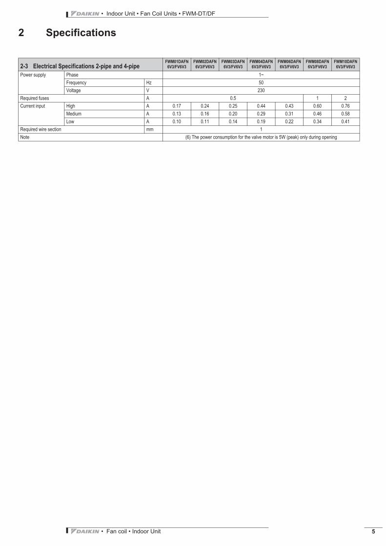
2-3 Electrical Specifications 2-pipe and 4-pipeFWM01DAFN
6V3/FV6V3FWM02DAFN
6V3/FV6V3FWM03DAFN
6V3/FV6V3FWM04DAFN
6V3/FV6V3FWM06DAFN
6V3/FV6V3FWM08DAFN
6V3/FV6V3FWM10DAFN
6V3/FV6V3
Power supply Phase 1~Frequency Hz 50Voltage V 230
Required fuses A 0.5 1 2Current input High A 0.17 0.24 0.25 0.44 0.43 0.60 0.76
Medium A 0.13 0.16 0.20 0.29 0.31 0.46 0.58Low A 0.10 0.11 0.14 0.19 0.22 0.34 0.41
Required wire section mm 1Note (6) The power consumption for the valve motor is 5W (peak) only during opening
• Indoor Unit • Fan Coil Units • FWM-DT/DF
• Fan coil • Indoor Unit6
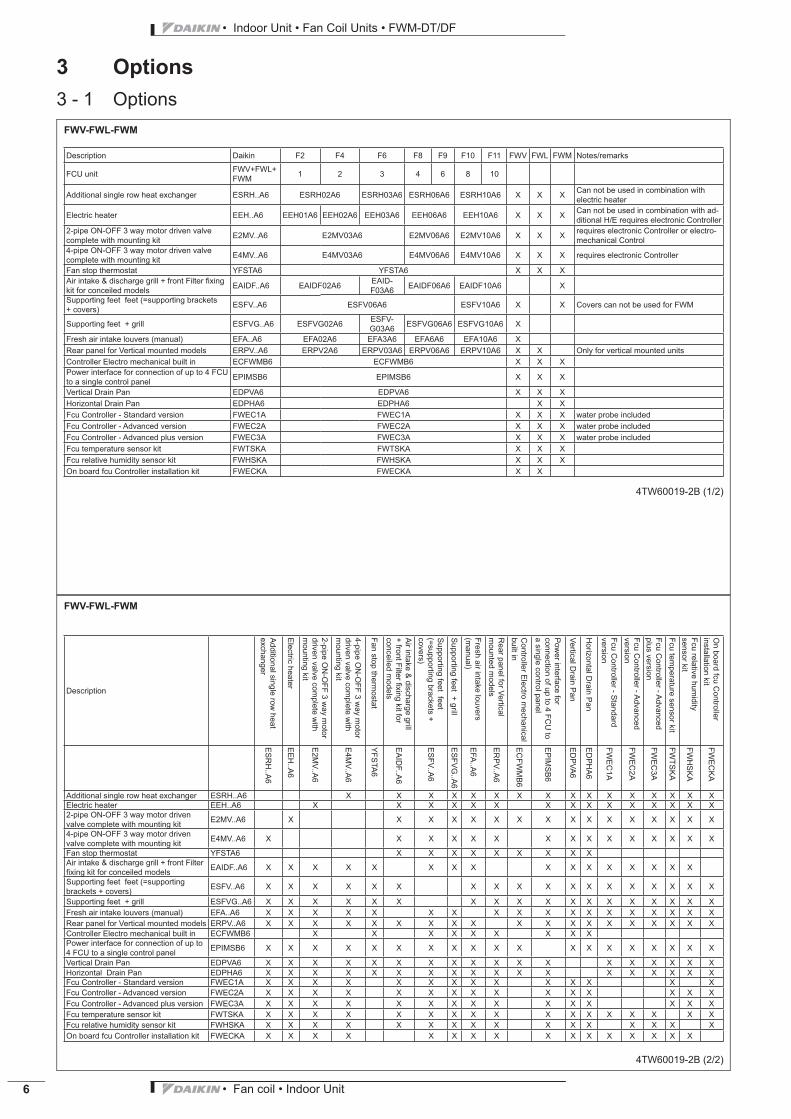
3 Options3 - 1 Options
• Fan coil • Indoor Unit 7
• Indoor Unit • Fan Coil Units • FWM-DT/DF
4 Control systems4 - 1 Control Systems
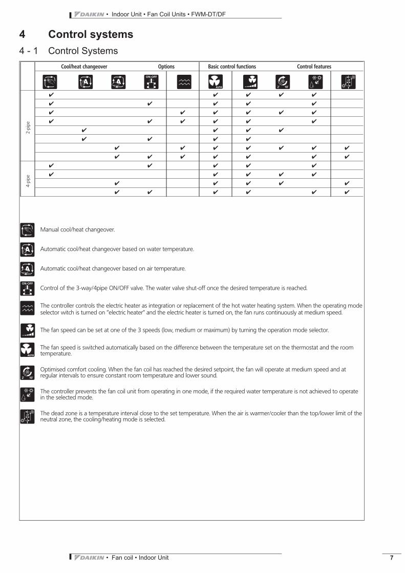
Cool/heat changeover Options Basic control functions Control features
7✔ ✔ ✔ ✔ ✔
✔ ✔ ✔ ✔ ✔
✔ ✔ ✔ ✔ ✔ ✔
✔ ✔ ✔ ✔ ✔ ✔
✔ ✔ ✔ ✔
✔ ✔ ✔ ✔
✔ ✔ ✔ ✔ ✔ ✔ ✔
✔ ✔ ✔ ✔ ✔ ✔ ✔
✔ ✔ ✔ ✔ ✔
✔ ✔ ✔ ✔ ✔
✔ ✔ ✔ ✔ ✔
✔ ✔ ✔ ✔ ✔ ✔
Manual cool/heat changeover.
Automatic cool/heat changeover based on water temperature.
Automatic cool/heat changeover based on air temperature.
Control of the 3-way/4pipe ON/OFF valve. The water valve shut-off once the desired temperature is reached.
The controller controls the electric heater as integration or replacement of the hot water heating system. When the operating modeselector witch is turned on ’’electric heater’’ and the electric heater is turned on, the fan runs continuously at medium speed.
The fan speed can be set at one of the 3 speeds (low, medium or maximum) by turning the operation mode selector.
7 The fan speed is switched automatically based on the difference between the temperature set on the thermostat and the roomtemperature.
Optimised comfort cooling. When the fan coil has reached the desired setpoint, the fan will operate at medium speed and atregular intervals to ensure constant room temperature and lower sound.
The controller prevents the fan coil unit from operating in one mode, if the required water temperature is not achieved to operatein the selected mode.
The dead zone is a temperature interval close to the set temperature. When the air is warmer/cooler than the top/lower limit of theneutral zone, the cooling/heating mode is selected.
4-pi
pe2-
pipe
• Indoor Unit • Fan Coil Units • FWM-DT/DF
• Fan coil • Indoor Unit8
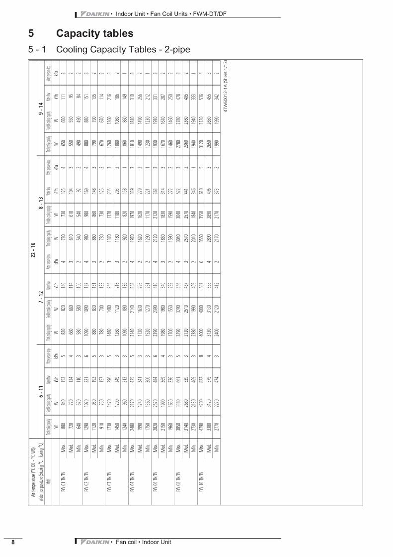
5 Capacity tables5 - 1 Cooling Capacity Tables - 2-pipe
Airtem
perature
(°CDB
-°CW
B)22
-16
Water
temper
ature
(Entering
°C-le
aving
°C)
6-1
17
-12
8-1
39
-14
Model
Totalcoolin
gcapacity
Sensiblec
oolingcap
acityWate
rflowWate
rpressure
dropTotal
coolingcap
acitySensi
blecoolin
gcapacity
Waterflow
Waterpre
ssuredrop
Totalcoolin
gcapacity
Sensiblec
oolingcap
acityWate
rflowWate
rpressure
dropTotal
coolingcap
acitySensi
blecoolin
gcapacity
Waterflow
Waterpre
ssuredrop
WW
!/h
kPa
WW
!/h
kPa
WW
!/h
kPa
WW
!/h
kPa
FW01
TN/TV
Max.
880
840
152
5820
820
140
4730
730
125
4650
650
111
3M
ed.
720
720
124
4660
660
114
3610
610
104
3550
550
952
Min.
640
570
110
3580
580
100
2540
540
922
490
490
842
FW02
TN/TV
Max.
1290
1070
221
61090
1090
187
4980
980
169
4880
880
151
3M
ed.
1120
930
192
5880
830
151
3860
860
148
3790
790
135
2M
in.910
750
157
3780
700
133
2730
730
125
2670
670
114
2FW
03TN/TV
Max.
1730
1470
296
51480
1480
255
31370
1370
235
31260
1260
216
3M
ed.
1450
1200
249
31260
1120
216
31180
1180
203
21080
1080
186
2M
in.1240
960
213
31090
890
186
2920
820
158
1860
860
149
1FW
04TN/TV
Max.
2480
2170
425
52140
2140
368
41970
1970
339
31810
1810
310
3M
ed.
1990
1740
341
31720
1630
295
21620
1620
279
21490
1490
256
2M
in.1750
1360
300
31520
1270
261
21290
1170
221
11230
1230
212
1FW
06TN/TV
Max.
2820
2570
484
62390
2390
410
42120
2120
363
31930
1930
331
3M
ed.
2150
1990
369
41980
1980
340
31830
1830
314
31670
1670
287
2M
in.1960
1650
336
31700
1550
292
21590
1590
272
21460
1460
250
2FW
08TN/TV
Max.
3850
3380
661
53290
3290
565
43040
3040
522
32780
2780
478
3M
ed.
3140
2680
539
32720
2510
467
32570
2570
441
22360
2360
405
2M
in.2730
2130
469
32380
1990
409
22010
1840
346
11940
1940
333
1FW
10TN/TV
Max.
4790
4200
822
84000
4000
687
63550
3550
610
53120
3120
536
4M
ed.
3380
3120
579
43130
3130
538
42890
2890
496
32650
2650
455
3M
in.2770
2270
474
32400
2120
412
22170
2170
373
21990
1990
342
2
4TW
6001
2-1A
(She
et1/
13)

• Fan coil • Indoor Unit 9
• Indoor Unit • Fan Coil Units • FWM-DT/DF
5 Capacity tables5 - 1 Cooling Capacity Tables - 2-pipe
Airtem
perature
(°CDB
-°CW
B)25
-18
Water
temper
ature
(Entering
°C-le
aving
°C)
6-1
17
-12
8-1
39
-14
Model
Totalcoolin
gcapacity
Sensiblec
oolingcap
acityWate
rflowWate
rpressure
dropTotal
coolingcap
acitySensi
blecoolin
gcapacity
Waterflow
Waterpre
ssuredrop
Totalcoolin
gcapacity
Sensiblec
oolingcap
acityWate
rflowWate
rpressure
dropTotal
coolingcap
acitySensi
blecoolin
gcapacity
Waterflow
Waterpre
ssuredrop
WW
!/h
kPa
WW
!/h
kPa
WW
!/h
kPa
WW
!/h
kPa
FW01
TN/TV
Max.
1480
1110
254
131260
1030
217
91020
940
175
6920
920
158
5M
ed.
1190
900
205
91010
830
174
6810
750
139
4740
740
126
4M
in.1000
740
172
6850
670
145
5680
610
117
3620
620
107
3FW
02TN/TV
Max.
2020
1410
346
131750
1300
300
101450
1190
250
71120
1060
193
4M
ed.
1750
1230
300
101520
1130
260
81260
1030
217
6970
920
167
3M
in.1400
980
240
71210
910
208
51000
820
172
4820
750
141
3FW
03TN/TV
Max.
2820
1970
484
112440
1820
419
82010
1640
345
61660
1660
284
4M
ed.
2290
1590
393
71970
1460
338
61590
1310
273
41320
1200
226
3M
in.1690
1180
290
41460
1080
251
31300
1020
224
31140
950
196
2FW
04TN/TV
Max.
4170
2940
715
123590
2710
617
92940
2450
504
62440
2440
418
4M
ed.
3140
2280
538
72670
2090
458
52080
1860
357
31880
1880
322
3M
in.2390
1670
410
42060
1540
354
31830
1440
315
31600
1350
274
2FW
06TN/TV
Max.
4600
3400
788
143970
3150
682
103280
2880
562
72690
2690
463
5M
ed.
3720
2720
639
93200
2510
549
72580
2270
443
52160
2160
371
4M
in.3040
2160
522
72580
1970
444
52050
1760
352
31780
1660
306
3FW
08TN/TV
Max.
6470
4590
1109
115590
4230
960
94590
3830
788
63730
3730
640
4M
ed.
5060
3580
868
74320
3270
741
63360
2890
578
42850
2690
489
3M
in.3780
2640
649
43230
2410
554
32870
2270
492
32500
2120
429
2FW
10TN/TV
Max.
7730
5560
1325
196690
5150
1148
155540
4700
951
104520
4520
776
7M
ed.
6000
4320
1030
125150
3980
885
94160
3590
714
63460
3460
595
5M
in.3920
2830
672
63270
2570
561
42900
2420
498
32520
2280
433
3
4TW
6001
2-1A
(She
et3/
13)
• Indoor Unit • Fan Coil Units • FWM-DT/DF
• Fan coil • Indoor Unit10
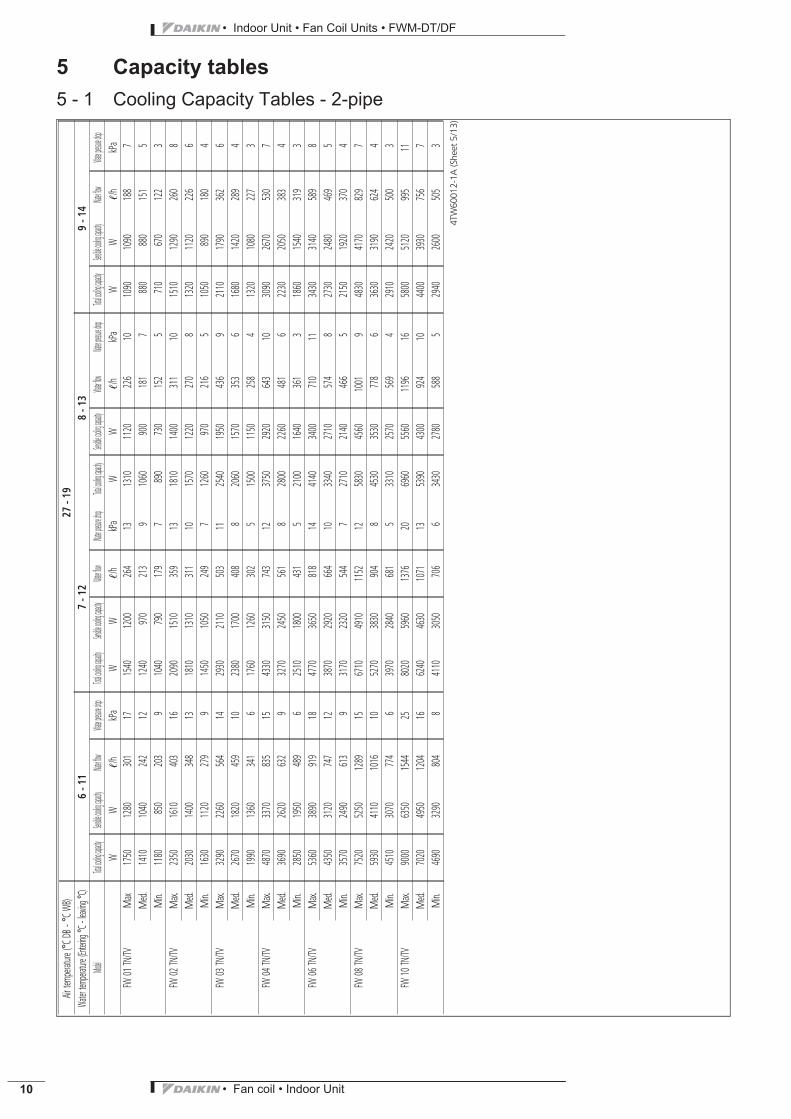
5 Capacity tables5 - 1 Cooling Capacity Tables - 2-pipe
Airtem
perature
(°CDB
-°CW
B)27
-19
Water
temper
ature
(Entering
°C-le
aving
°C)
6-1
17
-12
8-1
39
-14
Model
Totalcoolin
gcapacity
Sensiblec
oolingcap
acityWate
rflowWate
rpressure
dropTotal
coolingcap
acitySensi
blecoolin
gcapacity
Waterflow
Waterpre
ssuredrop
Totalcoolin
gcapacity
Sensiblec
oolingcap
acityWate
rflowWate
rpressure
dropTotal
coolingcap
acitySensi
blecoolin
gcapacity
Waterflow
Waterpre
ssuredrop
WW
!/h
kPa
WW
!/h
kPa
WW
!/h
kPa
WW
!/h
kPa
FW01
TN/TV
Max
1750
1280
301
171540
1200
264
131310
1120
226
101090
1090
188
7M
ed.
1410
1040
242
121240
970
213
91060
900
181
7880
880
151
5M
in.1180
850
203
91040
790
179
7890
730
152
5710
670
122
3FW
02TN/TV
Max.
2350
1610
403
162090
1510
359
131810
1400
311
101510
1290
260
8M
ed.
2030
1400
348
131810
1310
311
101570
1220
270
81320
1120
226
6M
in.1630
1120
279
91450
1050
249
71260
970
216
51050
890
180
4FW
03TN/TV
Max.
3290
2260
564
142930
2110
503
112540
1950
436
92110
1790
362
6M
ed.
2670
1820
459
102380
1700
408
82060
1570
353
61680
1420
289
4M
in.1990
1360
341
61760
1260
302
51500
1150
258
41320
1080
227
3FW
04TN/TV
Max.
4870
3370
835
154330
3150
743
123750
2920
643
103090
2670
530
7M
ed.
3690
2620
632
93270
2450
561
82800
2260
481
62230
2050
383
4M
in.2850
1950
489
62510
1800
431
52100
1640
361
31860
1540
319
3FW
06TN/TV
Max.
5360
3890
919
184770
3650
818
144140
3400
710
113430
3140
589
8M
ed.
4350
3120
747
123870
2920
664
103340
2710
574
82730
2480
469
5M
in.3570
2490
613
93170
2320
544
72710
2140
466
52150
1920
370
4FW
08TN/TV
Max.
7520
5250
1289
156710
4910
1152
125830
4560
1001
94830
4170
829
7M
ed.
5930
4110
1016
105270
3830
904
84530
3530
778
63630
3190
624
4M
in.4510
3070
774
63970
2840
681
53310
2570
569
42910
2420
500
3FW
10TN/TV
Max.
9000
6350
1544
258020
5960
1376
206960
5560
1196
165800
5120
995
11M
ed.
7020
4950
1204
166240
4630
1071
135390
4300
924
104400
3930
756
7M
in.4690
3290
804
84110
3050
706
63430
2780
588
52940
2600
505
3
4TW
6001
2-1A
(She
et5/
13)

• Fan coil • Indoor Unit 11
• Indoor Unit • Fan Coil Units • FWM-DT/DF
5 Capacity tables5 - 1 Cooling Capacity Tables - 2-pipe
Airtem
perature
(°CDB
-°CW
B)30
-22
Water
temper
ature
(Entering
°C-le
aving
°C)
6-1
17
-12
8-1
39
-14
Model
Totalcoolin
gcapacity
Sensiblec
oolingcap
acityWate
rflowWate
rpressure
dropTotal
coolingcap
acitySensi
blecoolin
gcapacity
Waterflow
Waterpre
ssuredrop
Totalcoolin
gcapacity
Sensiblec
oolingcap
acityWate
rflowWate
rpressure
dropTotal
coolingcap
acitySensi
blecoolin
gcapacity
Waterflow
Waterpre
ssuredrop
WW
!/h
kPa
WW
!/h
kPa
WW
!/h
kPa
WW
!/h
kPa
FW01
TN/TV
Max.
2640
1520
453
352440
1450
419
302240
1370
384
262020
1290
347
21M
ed.
2120
1230
364
241960
1170
337
211800
1110
309
181630
1050
279
15M
in.1770
1020
304
171640
960
282
151510
910
259
131360
860
234
11FW
02TN/TV
Max.
3430
1920
589
323190
1820
548
282940
1730
505
242680
1630
460
20M
ed.
2940
1660
505
252740
1580
471
222530
1500
435
192310
1410
397
16M
in.2360
1340
404
172200
1270
377
152030
1200
349
131860
1130
319
11FW
03TN/TV
Max.
4770
2690
818
274450
2550
764
244110
2410
706
203760
2280
645
17M
ed.
3880
2180
665
193620
2070
621
163350
1960
575
143060
1840
526
12M
in.2890
1630
495
112700
1550
463
102500
1460
429
92290
1370
393
7FW
04TN/TV
Max.
7110
4000
1220
306630
3800
1137
266120
3600
1050
225580
3400
958
19M
ed.
5400
3120
926
185030
2960
864
164650
2810
798
144240
2650
729
12M
in.4190
2350
719
123910
2230
671
103620
2110
621
93300
1980
567
8FW
06TN/TV
Max.
7810
4570
1340
347280
4350
1249
306720
4130
1153
266130
3910
1053
22M
ed.
6350
3690
1090
245920
3510
1016
215470
3330
939
184990
3140
857
15M
in.5220
2970
895
174870
2820
836
154500
2670
773
134110
2520
706
11FW
08TN/TV
Max.
10880
6210
1867
2910160
5900
1743
259400
5600
1613
228600
5280
1476
19M
ed.
8610
4890
1478
198040
4650
1381
177440
4400
1278
156810
4150
1169
12M
in.6630
3710
1137
126190
3520
1062
115730
3320
983
95230
3120
898
8FW
10TN/TV
Max.
13100
7470
2246
4812230
7120
2098
4211280
6760
1937
3611110
6840
1909
29M
ed.
10270
5860
1762
319570
5580
1642
278840
5290
1517
248680
5320
1491
19M
in.6950
3950
1193
166480
3750
1112
145980
3550
1026
125850
3540
1004
9
4TW
6001
2-1A
(She
et7/
13)

• Indoor Unit • Fan Coil Units • FWM-DT/DF
• Fan coil • Indoor Unit12
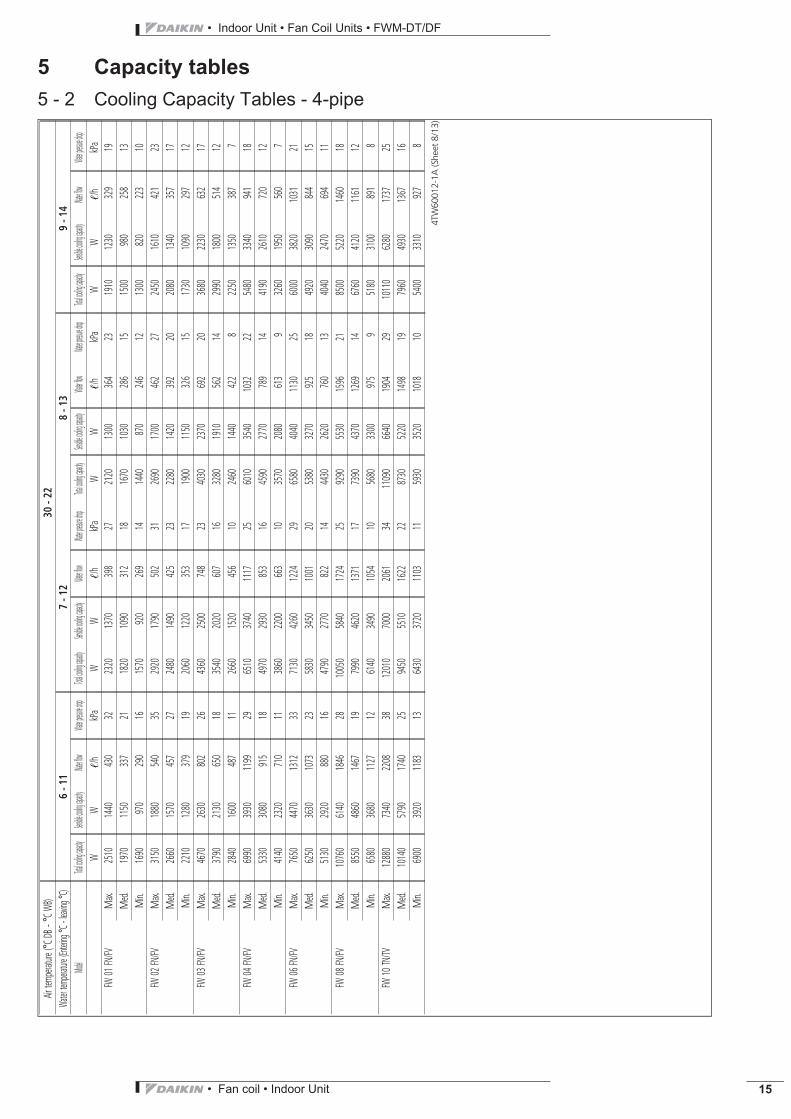
5 Capacity tables5 - 2 Cooling Capacity Tables - 4-pipe
Airtem
perature
(°CDB
-°CW
B)22
-16
Water
temper
ature
(Entering
°C-le
aving
°C)
6-1
17
-12
8-1
39
-14
Model
Totalcoolin
gcapacity
Sensiblec
oolingcap
acityWate
rflowWate
rpressure
dropTotal
coolingcap
acitySensi
blecoolin
gcapacity
Waterflow
Waterpre
ssuredrop
Totalcoolin
gcapacity
Sensiblec
oolingcap
acityWate
rflowWate
rpressure
dropTotal
coolingcap
acitySensi
blecoolin
gcapacity
Waterflow
Waterpre
ssuredrop
WW
!/h
kPa
WW
!/h
kPa
WW
!/h
kPa
WW
!/h
kPa
FW01
FN/FV
Max.
850
850
146
5770
770
132
4690
690
118
3620
620
107
3M
ed.
670
640
116
3620
620
107
3570
570
982
520
520
902
Min.
620
550
107
3560
560
962
520
520
892
470
470
812
FW02
FN/FV
Max.
1160
1080
199
6990
990
170
5900
900
154
4810
810
140
3M
ed.
980
890
167
5860
860
148
4790
790
136
3720
720
124
3M
in.870
740
149
4740
690
127
3690
690
118
2630
630
108
2FW
03FN/FV
Max.
1680
1430
289
41460
1460
251
31350
1350
232
31240
1240
213
2M
ed.
1440
1180
246
31250
1100
214
31160
1160
199
21070
1070
183
2M
in.1230
950
211
31080
880
185
2910
810
157
1850
850
147
1FW
04FN/FV
Max.
2420
2120
415
42110
2110
363
41950
1950
335
31790
1790
307
3M
ed.
1980
1720
339
31710
1610
294
21610
1610
276
21480
1480
254
2M
in.1740
1350
298
31510
1260
260
21280
1160
220
11220
1220
210
1FW
06FN/FV
Max.
2750
2500
471
52330
2330
400
42070
2070
356
31900
1900
326
3M
ed.
2140
1960
367
41960
1960
336
31810
1810
310
31660
1660
284
2M
in.1940
1630
334
31690
1520
289
21570
1570
269
21440
1440
247
2FW
08FN/FV
Max.
3790
3330
650
53270
3270
561
33020
3020
518
32760
2760
475
3M
ed.
3130
2660
537
32710
2490
465
22560
2560
439
22350
2350
403
2M
in.2720
2120
467
32370
1970
407
22010
1820
344
11930
1930
331
1FW
10TN/TV
Max.
4690
4120
803
73930
3930
674
53480
3480
597
43090
3090
530
3M
ed.
3360
3090
576
43110
3110
533
32870
2870
492
32630
2630
451
2M
in.2750
2260
472
32390
2110
410
22160
2160
370
21980
1980
340
1
4TW
6001
2-1A
(She
et2/
13)

• Fan coil • Indoor Unit 13
• Indoor Unit • Fan Coil Units • FWM-DT/DF
5 Capacity tables5 - 2 Cooling Capacity Tables - 4-pipe
Airtem
perature
(°CDB
-°CW
B)25
-18
Water
temper
ature
(Entering
°C-le
aving
°C)
6-1
17
-12
8-1
39
-14
Model
Totalcoolin
gcapacity
Sensiblec
oolingcap
acityWate
rflowWate
rpressure
dropTotal
coolingcap
acitySensi
blecoolin
gcapacity
Waterflow
Waterpre
ssuredrop
Totalcoolin
gcapacity
Sensiblec
oolingcap
acityWate
rflowWate
rpressure
dropTotal
coolingcap
acitySensi
blecoolin
gcapacity
Waterflow
Waterpre
ssuredrop
WW
!/h
kPa
WW
!/h
kPa
WW
!/h
kPa
WW
!/h
kPa
FW01
FN/FV
Max.
1400
1060
241
111190
980
205
9960
890
165
6870
870
149
5M
ed.
1100
840
188
7930
770
159
6740
700
127
4680
680
116
3M
in.950
700
163
6800
640
138
4660
590
113
3600
600
103
3FW
02FN/FV
Max.
1830
1400
315
141590
1300
272
111310
1200
226
81110
1110
190
6M
ed.
1560
1160
268
101350
1080
231
81110
990
191
6940
940
161
4M
in.1300
950
223
81120
870
192
6920
790
158
4780
740
134
3FW
03FN/FV
Max.
2770
1930
474
102390
1780
410
81970
1610
337
61620
1620
278
4M
ed.
2240
1560
384
71930
1420
330
51550
1270
266
41300
1180
224
3M
in.1660
1160
285
41450
1070
249
31290
1000
222
31130
940
194
2FW
04FN/FV
Max.
4100
2890
703
113530
2660
606
92880
2410
494
62390
2390
411
4M
ed.
3100
2250
532
72630
2060
452
52070
1840
355
31860
1860
320
3M
in.2360
1650
405
42050
1520
351
31820
1430
313
31590
1340
273
2FW
06FN/FV
Max.
4500
3320
772
133890
3080
668
103200
2810
550
72640
2640
453
5M
ed.
3660
2670
628
93150
2460
540
72530
2220
435
52120
2120
365
3M
in.2990
2120
513
62530
1940
435
52040
1740
350
31770
1640
303
3FW
08FN/FV
Max.
6390
4540
1097
115530
4180
949
94530
3780
778
63680
3680
633
4M
ed.
5020
3550
862
74290
3240
735
63330
2860
571
42840
2680
487
3M
in.3740
2620
642
43210
2390
551
32860
2250
490
32490
2110
427
2FW
10TN/TV
Max.
7590
5460
1301
156570
5050
1128
125430
4610
932
84430
4430
761
6M
ed.
5930
4260
1016
105090
3930
873
74090
3540
702
53420
3420
587
4M
in.3880
2800
665
53260
2550
559
32890
2410
496
32510
2260
431
2
4TW
6001
2-1A
(She
et4/
13)

• Indoor Unit • Fan Coil Units • FWM-DT/DF
• Fan coil • Indoor Unit14
5 Capacity tables5 - 2 Cooling Capacity Tables - 4-pipe
Airtem
perature
(°CDB
-°CW
B)27
-19
Water
temper
ature
(Entering
°C-le
aving
°C)
6-1
17
-12
8-1
39
-14
Model
Totalcoolin
gcapacity
Sensiblec
oolingcap
acityWate
rflowWate
rpressure
dropTotal
coolingcap
acitySensi
blecoolin
gcapacity
Waterflow
Waterpre
ssuredrop
Totalcoolin
gcapacity
Sensiblec
oolingcap
acityWate
rflowWate
rpressure
dropTotal
coolingcap
acitySensi
blecoolin
gcapacity
Waterflow
Waterpre
ssuredrop
WW
!/h
kPa
WW
!/h
kPa
WW
!/h
kPa
WW
!/h
kPa
FW01
FN/FV
Max.
1660
1220
285
151460
1140
250
121240
1060
213
91040
1040
178
7M
ed.
1300
970
223
101140
900
196
8970
840
166
6810
810
139
4M
in.1130
810
193
8990
750
169
6840
700
144
5670
640
115
3FW
02FN/FV
Max.
2140
1600
367
181900
1510
326
151650
1410
283
111300
1300
224
7M
ed.
1820
1330
312
141620
1250
278
111400
1160
240
91160
1070
199
6M
in.1510
1080
260
101350
1010
231
81170
940
200
6960
860
165
4FW
03FN/FV
Max.
3220
2210
552
132870
2070
493
112490
1910
427
82060
1750
354
6M
ed.
2610
1780
449
92330
1660
400
82010
1530
345
61640
1390
282
4M
in.1960
1340
336
61730
1240
297
51470
1130
253
31310
1070
225
3FW
04FN/FV
Max.
4780
3310
821
154260
3090
730
123680
2870
632
93030
2620
520
7M
ed.
3640
2590
625
93230
2420
554
72760
2230
474
62200
2010
377
4M
in.2820
1920
483
62480
1780
425
52080
1620
357
31850
1530
317
3FW
06FN/FV
Max.
5250
3800
900
174670
3570
802
144050
3320
696
113360
3060
577
8M
ed.
4280
3060
735
123810
2870
653
103290
2660
564
72680
2430
461
5M
in.3510
2440
603
83110
2280
534
72660
2100
457
52100
1880
361
3FW
08FN/FV
Max.
7430
5190
1275
156640
4850
1138
125760
4500
990
94770
4120
819
7M
ed.
5880
4080
1010
105230
3800
898
84500
3510
772
63600
3160
618
4M
in.4470
3050
767
63930
2820
675
53270
2550
562
32900
2400
497
3FW
10TN/TV
Max.
8840
6240
1516
207880
5850
1352
166840
5450
1173
125690
5020
977
9M
ed.
6930
4890
1190
136160
4570
1057
105320
4240
912
84340
3880
745
6M
in.4650
3260
797
64070
3020
699
53390
2750
581
42930
2580
503
3
4TW
6001
2-1A
(She
et6/
13)
• Fan coil • Indoor Unit 15
• Indoor Unit • Fan Coil Units • FWM-DT/DF
5 Capacity tables5 - 2 Cooling Capacity Tables - 4-pipe
Airtem
perature
(°CDB
-°CW
B)30
-22
Water
temper
ature
(Entering
°C-le
aving
°C)
6-1
17
-12
8-1
39
-14
Model
Totalcoolin
gcapacity
Sensiblec
oolingcap
acityWate
rflowWate
rpressure
dropTotal
coolingcap
acitySensi
blecoolin
gcapacity
Waterflow
Waterpre
ssuredrop
Totalcoolin
gcapacity
Sensiblec
oolingcap
acityWate
rflowWate
rpressure
dropTotal
coolingcap
acitySensi
blecoolin
gcapacity
Waterflow
Waterpre
ssuredrop
WW
!/h
kPa
WW
!/h
kPa
WW
!/h
kPa
WW
!/h
kPa
FW01
FN/FV
Max.
2510
1440
430
322320
1370
398
272120
1300
364
231910
1230
329
19M
ed.
1970
1150
337
211820
1090
312
181670
1030
286
151500
980
258
13M
in.1690
970
290
161570
920
269
141440
870
246
121300
820
223
10FW
02FN/FV
Max.
3150
1880
540
352920
1790
502
312690
1700
462
272450
1610
421
23M
ed.
2660
1570
457
272480
1490
425
232280
1420
392
202080
1340
357
17M
in.2210
1280
379
192060
1220
353
171900
1150
326
151730
1090
297
12FW
03FN/FV
Max.
4670
2630
802
264360
2500
748
234030
2370
692
203680
2230
632
17M
ed.
3790
2130
650
183540
2020
607
163280
1910
562
142990
1800
514
12M
in.2840
1600
487
112660
1520
456
102460
1440
422
82250
1350
387
7FW
04FN/FV
Max.
6990
3930
1199
296510
3740
1117
256010
3540
1032
225480
3340
941
18M
ed.
5330
3080
915
184970
2930
853
164590
2770
789
144190
2610
720
12M
in.4140
2320
710
113860
2200
663
103570
2080
613
93260
1950
560
7FW
06FN/FV
Max.
7650
4470
1312
337130
4260
1224
296580
4040
1130
256000
3820
1031
21M
ed.
6250
3630
1073
235830
3450
1001
205380
3270
925
184920
3090
844
15M
in.5130
2920
880
164790
2770
822
144430
2620
760
134040
2470
694
11FW
08FN/FV
Max.
10760
6140
1846
2810050
5840
1724
259290
5530
1596
218500
5220
1460
18M
ed.
8550
4860
1467
197990
4620
1371
177390
4370
1269
146760
4120
1161
12M
in.6580
3680
1127
126140
3490
1054
105680
3300
975
95180
3100
891
8FW
10TN/TV
Max.
12880
7340
2208
3812010
7000
2061
3411090
6640
1904
2910110
6280
1737
25M
ed.
10140
5790
1740
259450
5510
1622
228730
5220
1498
197960
4930
1367
16M
in.6900
3920
1183
136430
3720
1103
115930
3520
1018
105400
3310
927
8
4TW
6001
2-1A
(She
et8/
13)
• Indoor Unit • Fan Coil Units • FWM-DT/DF
• Fan coil • Indoor Unit16
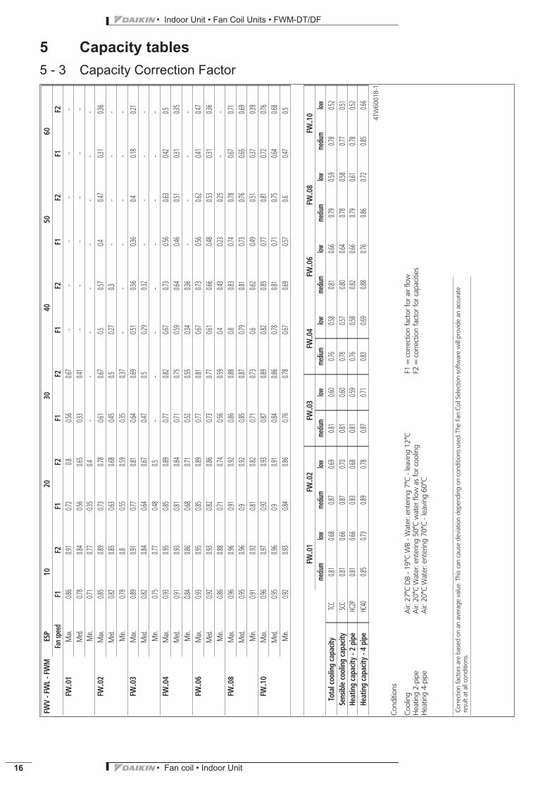
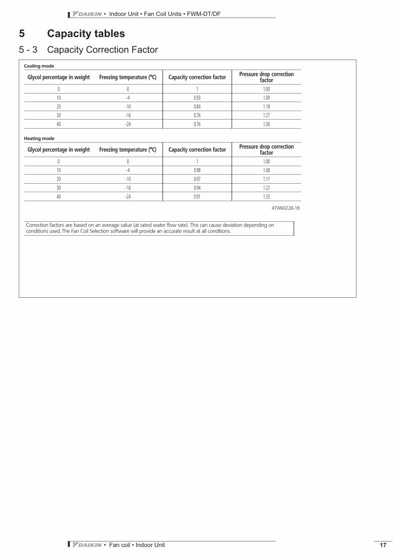
5 Capacity tables5 - 3 Capacity Correction Factor
FWV
-FW
L-F
WM
ESP
1020
3040
5060
Fans
peed
F1F2
F1F2
F1F2
F1F2
F1F2
F1F2
FW..0
1M
ax.0.8
60.9
10.7
20.8
0.56
0.67
--
--
--
Med.
0.78
0.84
0.56
0.65
0.33
0.41
--
--
--
Min.
0.71
0.77
0.35
0.4-
--
--
--
-FW
..02
Max.
0.85
0.89
0.73
0.78
0.61
0.67
0.50.5
70.4
0.47
0.31
0.36
Med.
0.82
0.85
0.63
0.68
0.45
0.50.2
70.3
--
--
Min.
0.78
0.80.5
50.5
90.3
50.3
7-
--
--
-FW
..03
Max.
0.89
0.91
0.77
0.81
0.64
0.69
0.51
0.56
0.36
0.40.1
80.2
1M
ed.
0.82
0.84
0.64
0.67
0.47
0.50.2
90.3
2-
--
-M
in.0.7
50.7
70.4
80.5
--
--
--
--
FW..0
4M
ax.0.9
30.9
50.8
50.8
90.7
70.8
20.6
70.7
30.5
60.6
30.4
20.5
Med.
0.91
0.93
0.81
0.84
0.71
0.75
0.59
0.64
0.46
0.51
0.31
0.35
Min.
0.84
0.86
0.68
0.71
0.52
0.55
0.34
0.36
--
--
FW..0
6M
ax.0.9
30.9
50.8
50.8
90.7
70.8
10.6
70.7
30.5
60.6
20.4
10.4
7M
ed.
0.92
0.93
0.82
0.86
0.73
0.77
0.61
0.66
0.48
0.53
0.31
0.36
Min.
0.86
0.88
0.71
0.74
0.56
0.59
0.40.4
30.2
30.2
5-
-FW
..08
Max.
0.96
0.96
0.91
0.92
0.86
0.88
0.80.8
30.7
40.7
80.6
70.7
1M
ed.
0.95
0.96
0.90.9
20.8
50.8
70.7
90.8
10.7
30.7
60.6
50.6
9M
in.0.9
10.9
20.8
10.8
20.7
10.7
30.6
0.62
0.49
0.51
0.37
0.39
FW..1
0M
ax.0.9
60.9
70.9
20.9
30.8
70.8
90.8
20.8
50.7
70.8
10.7
20.7
6M
ed.
0.95
0.96
0.90.9
10.8
40.8
60.7
80.8
10.7
10.7
50.6
40.6
8M
in.0.9
20.9
30.8
40.8
60.7
60.7
80.6
70.6
90.5
70.6
0.47
0.5
FW..0
1FW
..02
FW..0
3FW
..04
FW..0
6FW
..08
FW..1
0me
dium
lowme
dium
lowme
dium
lowme
dium
lowme
dium
lowme
dium
lowme
dium
lowTo
talc
oolin
gca
pacit
yTCC
0.81
0.68
0.87
0.69
0.81
0.60
0.76
0.58
0.81
0.66
0.79
0.59
0.78
0.52
Sens
ible
cooling
capa
city
SCC
0.81
0.66
0.87
0.70
0.81
0.60
0.78
0.57
0.80
0.64
0.78
0.58
0.77
0.51
Heat
ing
capa
city-2
pipe
HC2P
0.81
0.66
0.83
0.68
0.81
0.59
0.76
0.58
0.82
0.66
0.79
0.61
0.78
0.52
Heat
ing
capa
city-4
pipe
HC40
0.85
0.73
0.89
0.78
0.87
0.71
0.83
0.69
0.88
0.76
0.86
0.72
0.85
0.66
4TW
6001
8-1
Cond
ition
s
Cool
ing
Air:
27°C
DB
-19°
CW
B-W
ater
:ent
erin
g7°
C-l
eaving
12°C
F1=
corre
ctio
nfa
ctor
fora
irflo
wHea
ting
2-pi
peAir:
20°C
Wat
er:e
nter
ing
50°C
wat
erflo
was
forc
oolin
gF2
=co
rrect
ion
fact
orfo
rcap
acities
Hea
ting
4-pi
peAir:
20°C
Wat
er:e
nter
ing
70°C
-lea
ving
60°C
Corre
ctio
nfa
ctor
sar
eba
sed
onan
aver
age
value.
This
can
caus
ede
viat
ion
depe
nding
onco
ndition
sus
ed.T
heFa
nCo
ilSe
lect
ion
softw
are
will
prov
ide
anac
cura
tere
sult
atallc
ondi
tions
.
• Fan coil • Indoor Unit 17
• Indoor Unit • Fan Coil Units • FWM-DT/DF
5 Capacity tables5 - 3 Capacity Correction Factor
Cooling mode
Glycol percentage in weight Freezing temperature (°C) Capacity correction factor Pressure drop correctionfactor
0 0 1 1.00
10 -4 0.93 1.09
20 -10 0.84 1.18
30 -16 0.76 1.27
40 -24 0.76 1.36
Heating mode
Glycol percentage in weight Freezing temperature (°C) Capacity correction factor Pressure drop correctionfactor
0 0 1 1.00
10 -4 0.98 1.08
20 -10 0.97 1.11
30 -16 0.94 1.22
40 -24 0.91 1.33
4TW60228-1B
Correction factors are based on an average value (at rated water flow rate). This can cause deviation depending onconditions used. The Fan Coil Selection software will provide an accurate result at all conditions.
• Indoor Unit • Fan Coil Units • FWM-DT/DF
• Fan coil • Indoor Unit18
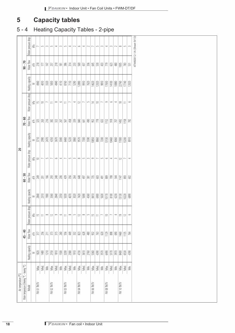
5 Capacity tables5 - 4 Heating Capacity Tables - 2-pipe
Airtem
perature
(°C)
20Wa
tertem
peratu
re(En
tering
°C-le
aving
°C)
45-4
060
-50
70-6
090
-70
Model
Heating
capaci
tyWa
terflow
Water
pressu
redro
pHeating
capaci
tyWa
terflow
Water
pressu
redro
pHeating
capaci
tyWa
terflow
Water
pressu
redro
pHeating
capaci
tyWa
terflow
Water
pressu
redro
pW
!/h
kPa
W!/h
kPa
W!/h
kPa
W!/h
kPa
FW01
TN/TV
Max.
1820
317
152840
249
103710
325
154940
218
7M
ed.
1480
256
112310
201
72990
263
104010
177
5M
in.1210
211
81900
166
52470
216
73320
147
3FW
02TN/TV
Max.
2150
373
123360
293
74350
382
115830
257
5M
ed.
1810
315
92840
248
63670
322
84940
218
4M
in.1500
260
62350
206
43040
267
64110
181
3FW
03TN/TV
Max.
3200
556
115030
439
76460
567
118760
386
5M
ed.
2580
449
84070
356
55220
458
77110
314
4M
in.1910
332
53020
264
33860
339
45290
233
2FW
04TN/TV
Max.
4730
823
127420
648
89570
840
1212890
569
6M
ed.
3610
628
85690
497
57300
641
79910
437
4M
in.2760
480
54360
381
35590
490
57620
336
2FW
06TN/TV
Max.
5360
932
158410
735
910850
952
1414620
645
7M
ed.
4390
763
116900
603
78860
778
1012020
530
5M
in.3570
620
75630
491
57200
632
79810
433
3FW
08TN/TV
Max.
6490
1129
1010170
889
613130
1152
917650
779
4M
ed.
5170
898
78100
708
410460
918
614100
623
3M
in.3970
690
46230
544
38060
707
410880
480
2FW
10TN/TV
Max.
8400
1460
1913130
1147
1217000
1492
1822760
1005
8M
ed.
6530
1135
1210220
893
713200
1158
1117740
783
5M
in.4390
764
66890
602
48910
782
612020
531
3
4TW
6001
2-1A
(She
et9/
13)
• Fan coil • Indoor Unit 19
• Indoor Unit • Fan Coil Units • FWM-DT/DF
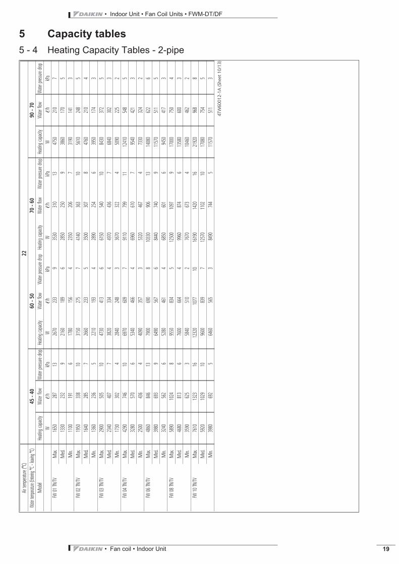
5 Capacity tables5 - 4 Heating Capacity Tables - 2-pipe
Airtem
perature
(°C)
22Wa
tertem
peratu
re(En
tering
°C-le
aving
°C)
45-4
060
-50
70-6
090
-70
Model
Heating
capaci
tyWa
terflow
Water
pressu
redro
pHeating
capaci
tyWa
terflow
Water
pressu
redro
pHeating
capaci
tyWa
terflow
Water
pressu
redro
pHeating
capaci
tyWa
terflow
Water
pressu
redro
pW
!/h
kPa
W!/h
kPa
W!/h
kPa
W!/h
kPa
FW01
TN/TV
Max.
1650
287
132670
233
93530
310
134750
210
7M
ed.
1330
232
92160
189
62850
250
93860
170
5M
in.1100
191
61780
156
42350
206
73190
141
3FW
02TN/TV
Max.
1950
338
103150
275
74140
363
105610
248
5M
ed.
1640
285
72660
233
53500
307
84760
210
4M
in.1360
236
52210
193
42890
254
63950
174
3FW
03TN/TV
Max.
2900
505
104730
413
66150
540
108430
372
5M
ed.
2340
407
73820
334
44970
436
76840
302
3M
in.1730
302
42840
248
33670
322
45090
225
2FW
04TN/TV
Max.
4290
746
106970
609
79110
799
1112410
548
5M
ed.
3280
570
65340
466
46960
610
79540
421
3M
in.2500
436
44090
357
35320
467
47330
324
2FW
06TN/TV
Max.
4860
846
137900
690
810330
906
1314080
622
6M
ed.
3980
693
96490
567
68440
740
911570
511
5M
in.3240
562
65280
461
46850
601
69450
417
3FW
08TN/TV
Max.
5890
1024
89550
834
512500
1097
917000
750
4M
ed.
4680
813
67600
664
49960
874
613580
600
3M
in.3590
625
35840
510
27670
673
410460
462
2FW
10TN/TV
Max.
7610
1323
1612320
1077
1016190
1420
1621920
968
8M
ed.
5920
1029
109600
839
712570
1102
1017080
754
5M
in.3980
692
56460
565
38490
744
511570
511
3
4TW
6001
2-1A
(She
et10
/13)
• Indoor Unit • Fan Coil Units • FWM-DT/DF
• Fan coil • Indoor Unit20
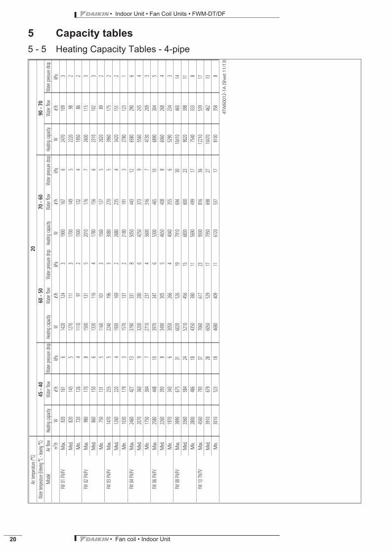
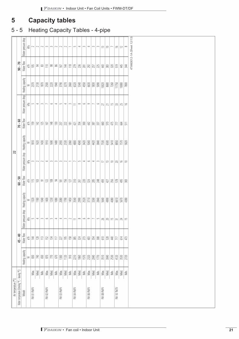
5 Capacity tables5 - 5 Heating Capacity Tables - 4-pipe
Airtem
perature
(°C)
20Wa
tertem
peratu
re(En
tering
°C-le
aving
°C)
45-4
060
-50
70-6
090
-70
Model
Airflow
Heating
capaci
tyWa
terflow
Water
pressu
redro
pHeating
capaci
tyWa
terflow
Water
pressu
redro
pHeating
capaci
tyWa
terflow
Water
pressu
redro
pHeating
capaci
tyWa
terflow
Water
pressu
redro
pm3
/hW
!/h
kPa
W!/h
kPa
W!/h
kPa
W!/h
kPa
FW01
FN/FV
Max.
920
161
61420
124
31900
167
62470
109
3M
ed.
820
143
51270
111
31700
149
52220
982
Min.
720
126
41110
972
1500
132
41950
862
FW02
FN/FV
Max.
980
170
81500
131
52010
176
72600
115
3M
ed.
860
150
61330
116
41780
156
62310
102
3M
in.750
131
51160
101
31560
137
52020
892
FW03
FN/FV
Max.
1470
255
52240
196
33080
270
53960
175
2M
ed.
1260
220
41930
169
22680
235
43420
151
2M
in.1030
179
31570
137
22180
191
32780
123
1FW
04FN/FV
Max.
2460
427
133790
331
85050
443
126580
290
6M
ed.
2070
360
93200
280
64250
373
95560
245
4M
in.1750
304
72710
237
43600
316
74730
209
3FW
06FN/FV
Max.
2580
448
103970
347
65300
465
106890
304
5M
ed.
2260
393
83490
305
54650
408
86060
268
4M
in.1970
343
63050
266
44040
355
65290
234
3FW
08FN/FV
Max.
3890
675
316020
526
197910
694
3010410
460
14M
ed.
3360
584
245210
456
156830
600
239020
398
11M
in.2800
486
184350
380
115690
499
177540
333
8FW
10TN/TV
Max.
4560
793
377060
617
239300
816
3612210
539
17M
ed.
3910
679
286050
529
177950
698
2710470
462
13M
in.3010
523
184680
409
116120
537
178100
358
8
4TW
6001
2-1A
(She
et11
/13)
• Fan coil • Indoor Unit 21
• Indoor Unit • Fan Coil Units • FWM-DT/DF
5 Capacity tables5 - 5 Heating Capacity Tables - 4-pipe
Airtem
perature
(°C)
22Wa
tertem
peratu
re(En
tering
°C-le
aving
°C)
45-4
060
-50
70-6
090
-70
Model
Heating
capaci
tyWa
terflow
Water
pressu
redro
pHeating
capaci
tyWa
terflow
Water
pressu
redro
pHeating
capaci
tyWa
terflow
Water
pressu
redro
pHeating
capaci
tyWa
terflow
Water
pressu
redro
pW
!/h
kPa
W!/h
kPa
W!/h
kPa
W!/h
kPa
FW01
FN/FV
Max.
830
144
51320
115
31810
159
52370
105
2M
ed.
740
128
41180
103
21620
142
42130
942
Min.
650
113
31040
912
1430
125
31870
832
FW02
FN/FV
Max.
870
152
61400
122
41910
167
72500
110
3M
ed.
770
134
51230
108
31690
148
62220
983
Min.
670
117
41080
943
1480
130
41940
862
FW03
FN/FV
Max.
1300
227
42080
181
32930
257
53790
167
2M
ed.
1120
195
31790
156
22530
222
43270
144
2M
in.910
158
21450
127
12060
181
32660
118
1FW
04FN/FV
Max.
2210
385
113540
310
74800
421
116320
279
5M
ed.
1860
324
82990
261
54040
354
85340
236
4M
in.1570
273
62520
220
43420
300
64550
201
3FW
06FN/FV
Max.
2320
403
93710
324
65040
442
96630
292
4M
ed.
2040
354
73260
285
44420
387
75830
257
3M
in.1770
308
52840
248
33840
337
65090
225
3FW
08FN/FV
Max.
3510
610
265640
493
177530
660
2710020
443
13M
ed.
3040
528
204890
427
136500
570
218680
383
10M
in.2530
440
154080
356
105410
475
157260
320
7FW
10TN/TV
Max.
4120
717
316610
578
208850
777
3311750
519
16M
ed.
3530
614
245670
495
167570
664
2510080
445
12M
in.2720
473
154380
383
105820
511
167800
344
8
4TW
6001
2-1A
(She
et12
/13)

• Indoor Unit • Fan Coil Units • FWM-DT/DF
• Fan coil • Indoor Unit22
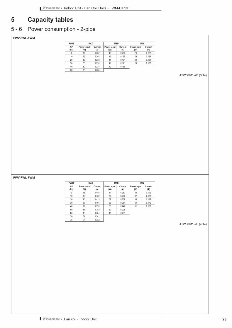
5 Capacity tables5 - 6 Power consumption - 2-pipe
FWV-FWL-FWM
4TW60011-2B (1/14)
FW01 MAX MED MIN
AP
(Pa)
Power input
(W)
Current
(A)
Power input
(W)
Current
(A)
Power input
(W)
Current
(A)
0 37 0.170 28 0.130 21 0.10010 37 0.160 26 0.120 21 0.09020 35 0.150 25 0.110 20 0.08830 35 0.150 24 0.11045 34 0.14050 33 0.140
FWV-FWL-FWM
4TW60011-2B (2/14)
FW02 MAX MED MIN
AP
(Pa)
Power input
(W)
Current
(A)
Power input
(W)
Current
(A)
Power input
(W)
Current
(A)
0 53 0.240 36 0.160 24 0.11010 52 0.235 32 0.142 21 0.09620 48 0.217 31 0.138 21 0.09630 46 0.208 31 0.138 20 0.09240 46 0.208 30 0.133
• Fan coil • Indoor Unit 23
• Indoor Unit • Fan Coil Units • FWM-DT/DF
5 Capacity tables5 - 6 Power consumption - 2-pipe
FWV-FWL-FWM
4TW60011-2B (3/14)
FW03 MAX MED MIN
AP
(Pa)
Power input
(W)
Current
(A)
Power input
(W)
Current
(A)
Power input
(W)
Current
(A)
0 56 0.252 43 0.200 29 0.13810 55 0.248 42 0.195 29 0.13420 53 0.239 41 0.191 29 0.13130 53 0.239 41 0.191 28 0.13040 52 0.234 40 0.18650 51 0.230
FWV-FWL-FWM
4TW60011-2B (4/14)
FW04 MAX MED MIN
AP
(Pa)
Power input
(W)
Current
(A)
Power input
(W)
Current
(A)
Power input
(W)
Current
(A)
0 98 0.440 61 0.287 38 0.19210 94 0.422 59 0.276 37 0.18720 92 0.413 57 0.259 36 0.18230 90 0.404 55 0.254 34 0.17240 88 0.395 53 0.242 31 0.15750 85 0.382 50 0.22860 81 0.364 45 0.21170 76 0.34175 74 0.332
• Indoor Unit • Fan Coil Units • FWM-DT/DF
• Fan coil • Indoor Unit24
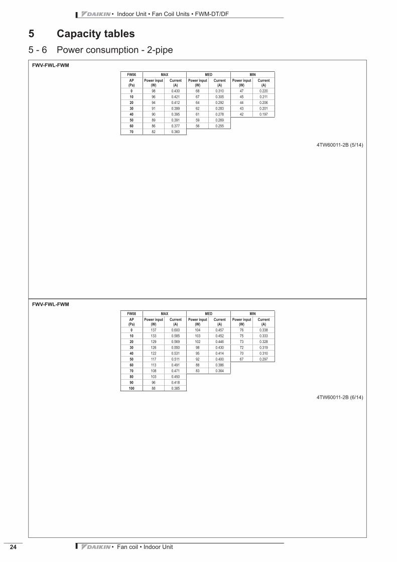
5 Capacity tables5 - 6 Power consumption - 2-pipe
FWV-FWL-FWM
4TW60011-2B (5/14)
FW06 MAX MED MIN
AP
(Pa)
Power input
(W)
Current
(A)
Power input
(W)
Current
(A)
Power input
(W)
Current
(A)
0 98 0.430 68 0.310 47 0.22010 96 0.421 67 0.305 45 0.21120 94 0.412 64 0.292 44 0.20630 91 0.399 62 0.283 43 0.20140 90 0.395 61 0.278 42 0.19750 89 0.391 59 0.26960 86 0.377 56 0.25570 82 0.360
FWV-FWL-FWM
4TW60011-2B (6/14)
FW08 MAX MED MIN
AP
(Pa)
Power input
(W)
Current
(A)
Power input
(W)
Current
(A)
Power input
(W)
Current
(A)
0 137 0.600 104 0.457 76 0.33810 133 0.585 103 0.452 75 0.33320 129 0.569 102 0.446 73 0.32830 126 0.550 98 0.430 72 0.31940 122 0.531 95 0.414 70 0.31050 117 0.511 92 0.400 67 0.29760 113 0.491 88 0.38670 108 0.471 83 0.36480 103 0.45090 96 0.418
100 88 0.385

• Fan coil • Indoor Unit 25
• Indoor Unit • Fan Coil Units • FWM-DT/DF
5 Capacity tables5 - 6 Power consumption - 2-pipe
FWV-FWL-FWM
4TW60011-2B (7/14)
FW10 MAX MED MIN
AP
(Pa)
Power input
(W)
Current
(A)
Power input
(W)
Current
(A)
Power input
(W)
Current
(A)
0 175 0.764 130 0.578 90 0.41410 170 0.742 128 0.567 88 0.40520 165 0.720 125 0.556 86 0.39630 161 0.701 121 0.536 84 0.38640 156 0.681 116 0.516 82 0.37750 150 0.655 112 0.496 79 0.36360 144 0.629 107 0.47670 139 0.605 102 0.45180 133 0.581 9690 127 0.552 92100 120 0.524
• Indoor Unit • Fan Coil Units • FWM-DT/DF
• Fan coil • Indoor Unit26
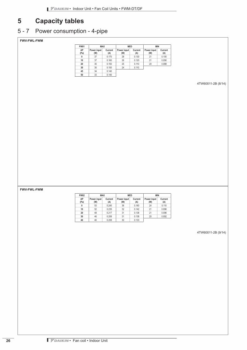
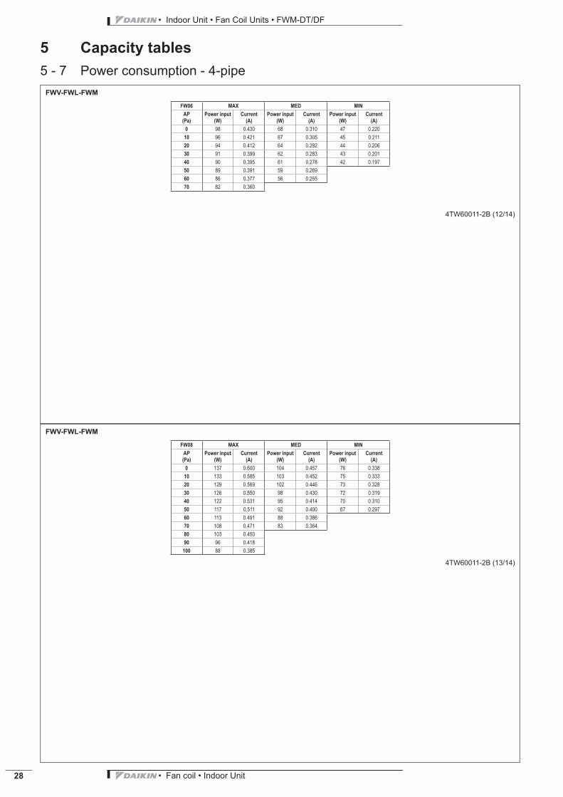
5 Capacity tables5 - 7 Power consumption - 4-pipe
FWV-FWL-FWM
4TW60011-2B (8/14)
FW01 MAX MED MIN
AP
(Pa)
Power input
(W)
Current
(A)
Power input
(W)
Current
(A)
Power input
(W)
Current
(A)
0 37 0.170 28 0.130 21 0.10010 37 0.160 26 0.120 21 0.09020 35 0.150 25 0.110 20 0.08830 35 0.150 24 0.11045 34 0.14050 33 0.140
FWV-FWL-FWM
4TW60011-2B (9/14)
FW02 MAX MED MIN
AP
(Pa)
Power input
(W)
Current
(A)
Power input
(W)
Current
(A)
Power input
(W)
Current
(A)
0 53 0.240 36 0.160 24 0.11010 52 0.235 32 0.142 21 0.09620 48 0.217 31 0.138 21 0.09630 46 0.208 31 0.138 20 0.09240 46 0.208 30 0.133

• Fan coil • Indoor Unit 27
• Indoor Unit • Fan Coil Units • FWM-DT/DF
5 Capacity tables5 - 7 Power consumption - 4-pipe
FWV-FWL-FWM
4TW60011-2B (10/14)
FW03 MAX MED MIN
AP
(Pa)
Power input
(W)
Current
(A)
Power input
(W)
Current
(A)
Power input
(W)
Current
(A)
0 56 0.252 43 0.200 29 0.13810 55 0.248 42 0.195 29 0.13420 53 0.239 41 0.191 29 0.13130 53 0.239 41 0.191 28 0.13040 52 0.234 40 0.18650 51 0.230
FWV-FWL-FWM
4TW60011-2B (11/14)
FW04 MAX MED MIN
AP
(Pa)
Power input
(W)
Current
(A)
Power input
(W)
Current
(A)
Power input
(W)
Current
(A)
0 98 0.440 61 0.287 38 0.19210 94 0.422 59 0.276 37 0.18720 92 0.413 57 0.259 36 0.18230 90 0.404 55 0.254 34 0.17240 88 0.395 53 0.242 31 0.15750 85 0.382 50 0.22860 81 0.364 45 0.21170 76 0.34175 74 0.332
• Indoor Unit • Fan Coil Units • FWM-DT/DF
• Fan coil • Indoor Unit28
5 Capacity tables5 - 7 Power consumption - 4-pipe
FWV-FWL-FWM
4TW60011-2B (12/14)
FW06 MAX MED MIN
AP
(Pa)
Power input
(W)
Current
(A)
Power input
(W)
Current
(A)
Power input
(W)
Current
(A)
0 98 0.430 68 0.310 47 0.22010 96 0.421 67 0.305 45 0.21120 94 0.412 64 0.292 44 0.20630 91 0.399 62 0.283 43 0.20140 90 0.395 61 0.278 42 0.19750 89 0.391 59 0.26960 86 0.377 56 0.25570 82 0.360
FWV-FWL-FWM
4TW60011-2B (13/14)
FW08 MAX MED MIN
AP
(Pa)
Power input
(W)
Current
(A)
Power input
(W)
Current
(A)
Power input
(W)
Current
(A)
0 137 0.600 104 0.457 76 0.33810 133 0.585 103 0.452 75 0.33320 129 0.569 102 0.446 73 0.32830 126 0.550 98 0.430 72 0.31940 122 0.531 95 0.414 70 0.31050 117 0.511 92 0.400 67 0.29760 113 0.491 88 0.38670 108 0.471 83 0.36480 103 0.45090 96 0.418
100 88 0.385
• Fan coil • Indoor Unit 29
• Indoor Unit • Fan Coil Units • FWM-DT/DF
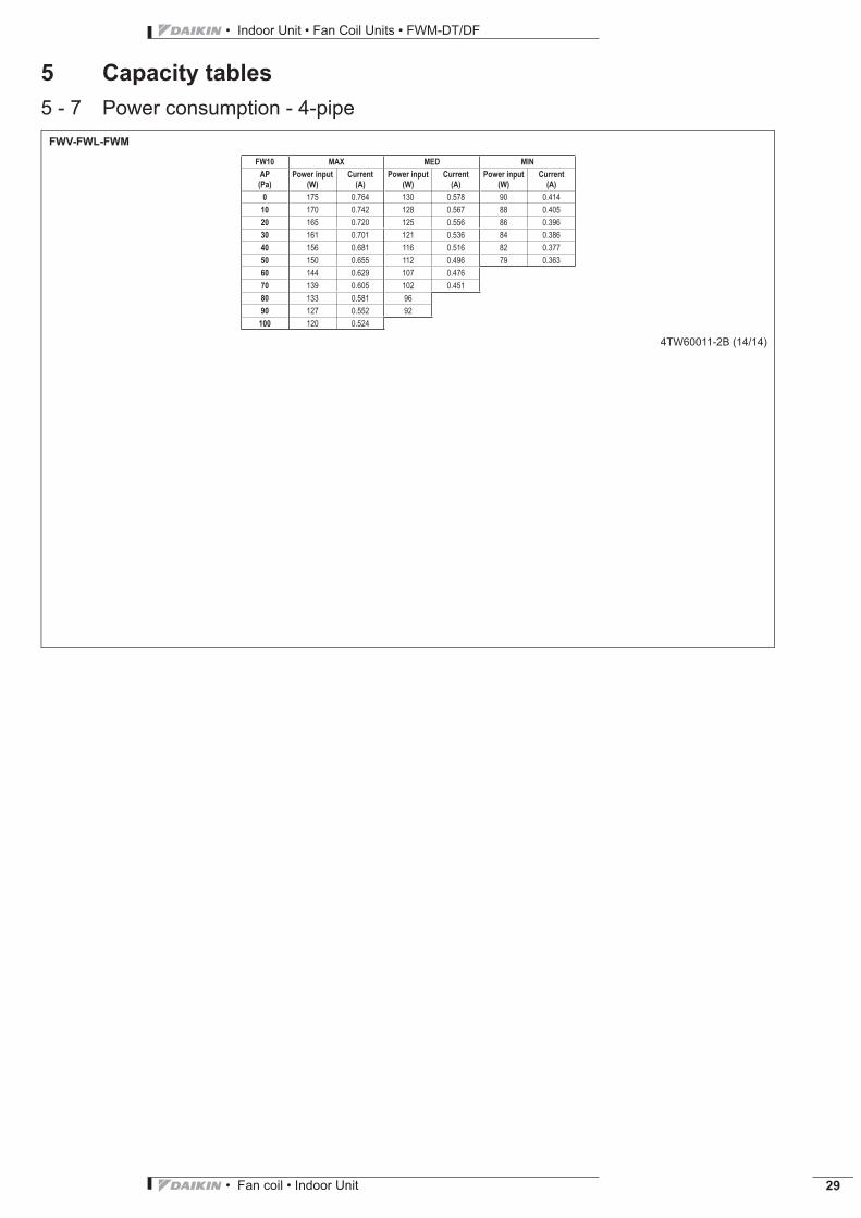
5 Capacity tables5 - 7 Power consumption - 4-pipe
FWV-FWL-FWM
4TW60011-2B (14/14)
FW10 MAX MED MIN
AP
(Pa)
Power input
(W)
Current
(A)
Power input
(W)
Current
(A)
Power input
(W)
Current
(A)
0 175 0.764 130 0.578 90 0.41410 170 0.742 128 0.567 88 0.40520 165 0.720 125 0.556 86 0.39630 161 0.701 121 0.536 84 0.38640 156 0.681 116 0.516 82 0.37750 150 0.655 112 0.496 79 0.36360 144 0.629 107 0.47670 139 0.605 102 0.45180 133 0.581 9690 127 0.552 92100 120 0.524
• Indoor Unit • Fan Coil Units • FWM-DT/DF
• Fan coil • Indoor Unit30
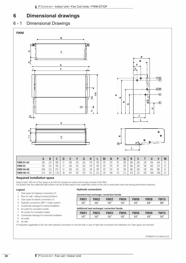
6 Dimensional drawings6 - 1 Dimensional Drawings
4TW60014-1A (Sheet 2/2)
FWM
A B C D E F G H L M N P Q R S T U V WFWM 01+02 584 224 498 51 458 163 263 149 198 187 335 99 189 486 208 198 436 464 61FWM 03 794 224 708 51 458 163 263 149 198 187 335 99 189 486 208 198 646 674 61FWM 04+06 1004 224 918 51 458 163 263 149 198 187 335 99 189 486 208 198 856 884 61FWM 08+10 1214 249 1128 48 497 185 259 155 220 195 348 120 215 478 234 208 1066 1094 67
Required installation spaceKeep at least 100 mm of free space at air inlet for a proper air suction and an easy removal of the filter.For ducted units the outlet/inlet grill surface must be at least equal to the outlet/inlet surface of the unit to avoid extra noise and strong performance reduction.
Legend1 Clear space for hydraulic connections (*)2 Slots for wall / ceiling mounting 9x20mm3 Clear space for electric connections (*)4 Hydraulic connections (4DF = 4 pipe system)5 Condensate drainage for vertical installation6 Air outlet for concealed models7 Air suction for concealed models8 Condensate drainage for horizontal installation9 Air outlet
10 Air inlet(*) Indications applicable to fan coils with hydraulic connections on the left side; in case of right side connections the indications for ’’clear space’’ are reversed.
Hydraulic connections
Standard heat exchanger: connection female
FW01 FW02 FW03 FW04 FW06 FW08 FW101/2″ 1/2″ 1/2″ 1/2″ 1/2″ 3/4″ 3/4″
Additional heat exchanger: connection female
FW01 FW02 FW03 FW04 FW06 FW08 FW101/2″ 1/2″ 1/2″ 1/2″ 1/2″ 1/2″ 1/2″
• Fan coil • Indoor Unit 31
• Indoor Unit • Fan Coil Units • FWM-DT/DF
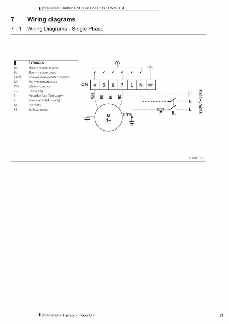
7 Wiring diagrams7 - 1 Wiring Diagrams - Single Phase
4TW60016-1
SYMBOLSBK Black = maximum speed
BU Blue = medium speed
GNYE Yellow/Green = earth connection
RD Red = minimum speed
WH White = common
---- Field wiring
F Protection fuse (field supply)
IL Main switch (field supply)
M Fan motor
PE Earth connection
• Indoor Unit • Fan Coil Units • FWM-DT/DF
• Fan coil • Indoor Unit32
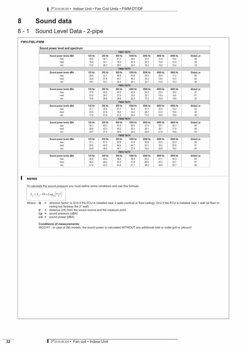
8 Sound data8 - 1 Sound Level Data - 2-pipe
FWV-FWL-FWM
Sound power level and spectrum
FW01 TN/TV
Sound power levels dBA 125 Hz 250 Hz 500 Hz 1000 Hz 2000 Hz 4000 Hz 8000 Hz Global Lw
max 24.8 39.1 41.7 38.4 33.7 21.6 15.6 45med 19.4 34.1 35.9 30.3 24.3 15.8 15.4 39min 13.6 29.7 29.0 22.0 16.2 15.2 15.2 33
FW02 TN/TV
Sound power levels dBA 125 Hz 250 Hz 500 Hz 1000 Hz 2000 Hz 4000 Hz 8000 Hz Global Lw
max 28.8 42.7 45.8 43.6 39.3 29.9 17.2 50med 22.9 37.8 40.7 36.2 30.3 19.6 15.4 44min 18.0 33.1 35.4 29.1 22.7 15.5 15.3 38
FW03 TN/TV
Sound power levels dBA 125 Hz 250 Hz 500 Hz 1000 Hz 2000 Hz 4000 Hz 8000 Hz Global Lw
max 27.8 40.9 43.5 40.4 34.0 23.4 18.0 47med 23.0 36.0 37.9 33.0 25.7 18.4 16.6 41min 15.6 28.8 28.8 22.0 17.2 16.0 15.6 33
FW04 TN/TV
Sound power levels dBA 125 Hz 250 Hz 500 Hz 1000 Hz 2000 Hz 4000 Hz 8000 Hz Global Lw
max 31.7 45.4 47.7 45.4 41.7 32.0 19.2 52med 23.6 37.6 39.8 34.2 28.7 21.6 16.5 43min 17.8 31.8 31.5 24.4 17.2 16.5 15.4 35
FW06 TN/TV
Sound power levels dBA 125 Hz 250 Hz 500 Hz 1000 Hz 2000 Hz 4000 Hz 8000 Hz Global Lw
max 36.1 49.3 51.4 50.6 47.4 39.1 24.7 56med 28.9 43.0 45.2 42.3 36.1 28.1 17.9 49min 23.7 37.4 39.8 34.4 28.6 21.9 16.8 43
FW08 TN/TV
Sound power levels dBA 125 Hz 250 Hz 500 Hz 1000 Hz 2000 Hz 4000 Hz 8000 Hz Global Lw
max 37.1 51.3 52.8 51.6 49.8 43.5 32.3 58med 30.6 44.9 46.4 44.7 42.1 33.2 20.9 51min 24.8 38.8 39.1 37.4 32.6 22.8 18.2 44
FW10 TN/TV
Sound power levels dBA 125 Hz 250 Hz 500 Hz 1000 Hz 2000 Hz 4000 Hz 8000 Hz Global Lw
max 42.6 56.0 58.2 58.4 56.5 51.7 44.4 64med 36.6 49.6 52.9 51.6 49.5 43.2 32.7 57min 27.8 42.3 43.8 41.7 38.3 28.6 20.7 48
NOTES
To calculate the sound pressure you must defi ne some conditions and use this formula
Lp
Lw10 Log
10
4 d ²
Q
Where: Q = direction factor: is Q=4 if the FCU is installed near 2 walls (vertical or fl oor-ceiling). Q=2 if the FCU is installed near 1 wall (at fl oor or
ceiling but faraway the 2° wall)
d = distance (mt) from the sound source and the measure point
Lp = sound pressure (dBA)
Lw = sound power (dBA)
Conditions of measurements:
ISO3741 : In case of (M) models, the sound power is calculated WITHOUT any additional inlet or outlet grill or plenum!
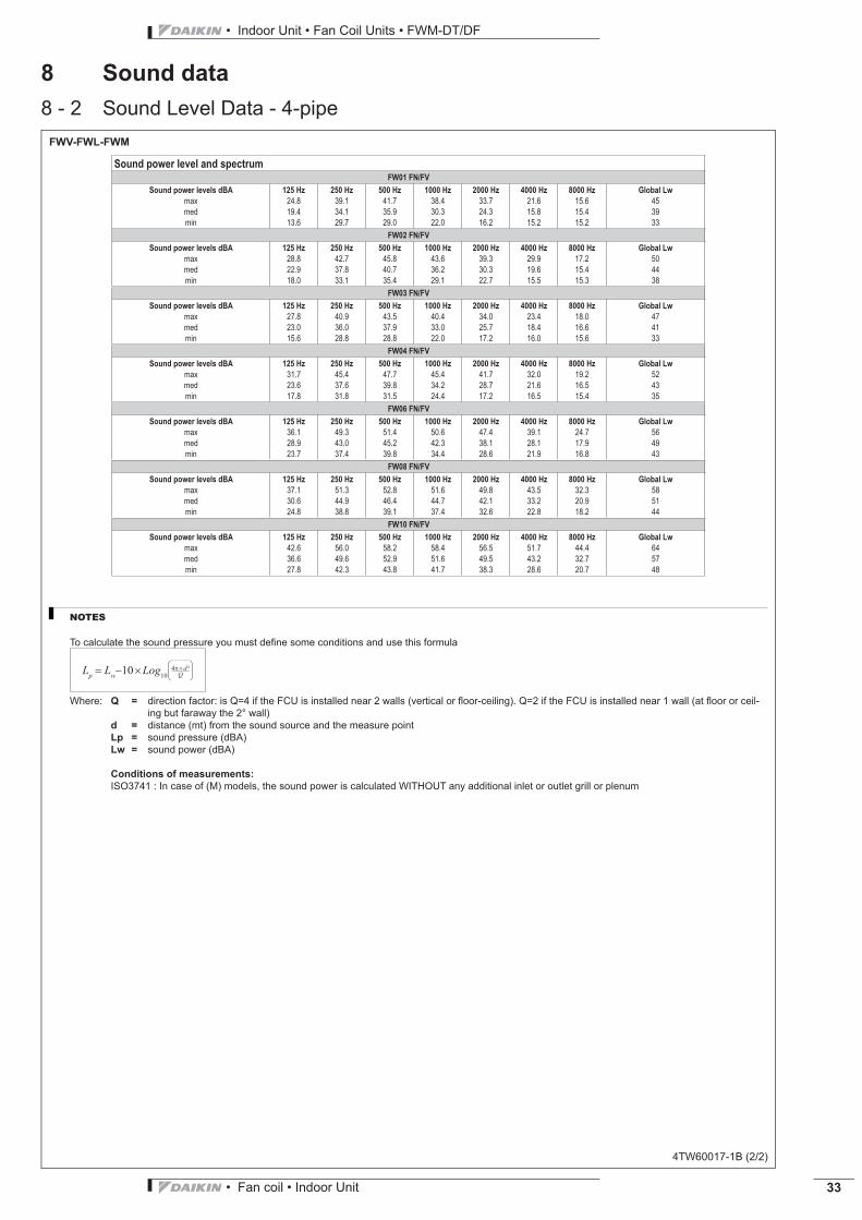
• Fan coil • Indoor Unit 33
• Indoor Unit • Fan Coil Units • FWM-DT/DF
8 Sound data8 - 2 Sound Level Data - 4-pipe
• Indoor Unit • Fan Coil Units • FWM-DT/DF
• Fan coil • Indoor Unit34
9 Installation9 - 1 Installation MethodFan coil units should be installed in a position where they heat and cool the room evenly, on walls or ceilings that can bear their weight.Fit any accessories on the standard unit before installing it. Read the relevant technical sheets for the installation and use of theaccessories. Keep free space around the fan coil to allow proper operation and ordinary and extraordinary maintenance (see the ’’9.Dimensional drawings’’) Provide a panel to reach the unit in case of recessed mounting (Concealed models).Install the remote control panel, if any, in a position that can easily be reached by the user to set the functions and that is suitable for theproper detection of the temperature, if provided.
Therefore avoid:- positions directly exposed to sunlight;- positions exposed to hot or cold draughts;- obstacles preventing the proper temperature detectionIf the system is shut down during the winter months, drain off the water from the system to prevent damage due to freezing; if antifreezesolutions are used, check the freezing point using the table shown on technical manual.
Keep at least 100 mm of free space at air inlet for a proper air suction and an easy removal of the filter.For ducted units the outlet/inlet grill surface must be at least equal to the outlet/inlet surface of the unit to avoid extra noise and strongperformance reduction.
BEFORE THE INSTALLATION
Installation and maintenance should be carried out by technical personnel qualified for this type of machine, in compliance with currentsafety regulations.For installation and use of possible accessories please refer to the pertinent technical sheets.In choosing where to install the unit, comply with the following points:- the heating unit should not be placed immediately under a socket- do not install the unit in rooms where inflammable gases are present- do not let water is sprayed directly on the unit- install the unit on ceilings or walls that bear its weight. Leave enough space all around for proper operation and maintenance of the unit.Keep the unit in its packaging until it is ready to be installed, to prevent dust getting inside it.
INSTALLATION WARNING:
On the fan coil install a switch (IL) and/or all remote controls in a position out of the reach of persons who are in a bathtubor shower.
In case of ceiling-mounted models, check that the installation height does not exceed the maximum height shown in 7. Dimensionaldrawings in order to avoid excessive hot air stratification in the upper part of the room; in case of greater installation heights we suggest toproceed with the back suction from the lower part of the room. The installation heights shown in the figure refer to the maximum runningspeed.Carry out the hydraulic connections to the heat exchanger and in case of cooling operation, to the water drainage system.We suggest toprovide for the water inlet from the bottom side of the heat exchanger and the outlet on the upper side. Bleed the air from the heatexchanger operating on the air-vent valves (10 hexagon wrench) located beside the water connections of the heat exchanger. For a betterwater drainage lean the drain pipe downwards at least 3 cm/m avoiding loops or narrowing on its way.
INSTALLATION FOR THE CONCEALED CEILING MODEL
The air outlets should not be placed immediately under a socket. For the concealed ceiling model, perform the connection between the fancoil and the ducts, and place damping material between the duct and the unit. The ducts, in particular the outlet ones, must be insulated. Inorder to avoid air back suction on the fan coil, keep a minimum distance between the air outlet and recovered air flow as shown ininstallation manual of the unit. The minimum installation height should not be lower than 1.8 metres from floor level. Provide for aninspection port to the unit.
• Fan coil • Indoor Unit 35
• Indoor Unit • Fan Coil Units • FWM-DT/DF
9 Installation9 - 1 Installation MethodELECTRICAL CONNECTIONS
Carry out the electrical wiring after having turned the power off in compliance with the relevant local and national regulations following therelevant wiring diagram.Check that the power supply corresponds to the rated power reported on the unit nameplate.
Each fan coil requires a switch (IL) on the feeder line with a distance of at least 3 mm between the opening contacts, and a suitable safetyfuse (F).
USE
To use the fan coil unit, refer to the instructions of the control panel, available as accessory.Air outlet grids on the cover cabinet (wall mounted and floor/ceiling mounted) can be turned 180° to direct the flow into the room ortowards the wall on which the unit is mounted. The grids and the side doors are snapped into the cabinet. Before removing them in orderto change their position, cut the power off and wear protective gloves.
MAINTENANCE
For safety reasons before carrying out any maintenance or cleaning operation, switch off the unit turning the selection switch to ’’Stop’’ andthe power supply switch on position 0 (OFF).Be careful during any maintenance operation; you could get injured by some metal parts; use protective work gloves. The fan coils do norequire any particular maintenance operation: only the periodical cleaning of the air filter should be carried out. It is necessary to carry out arunning in period of 100 hours in order to eliminate all mechanical friction. The starting up must be carried out at the maximum speed.For good operation of the fan coils follow the instructions below:- keep the air filter clean;- do not pour liquids into the unit;- do not introduce metal parts through the air outlet grid;- keep the air inlet and outlet free at all times.Each time the machine is turned on after being idle for a long period, ensure there is no air in the heat exchanger. Before using the unit forair conditions, check that:- condensate drainage is performed correctly:- the heat exchanger fins are not obstructed by deposits of dirt.If necessary clean the fins with low pressure compressed air or steam without damaging them.
CLEANING
For safety reasons before carrying out any maintenance or cleaning operation switch off the unit turning the selectionswitch to ’’Stop’’ and the power supply switch on 0 (OFF).
Clean the filter at least once a month and in any case before using the unit (before the heating or the air conditioning season).For cleaning the air filter proceed as follows (pictures see manual of units):- Floor models: turn the screws 90°, which secure the filter to the cover cabinet, to 1/4 turn and remove the filter;- Concealed models: reach the fan coil through the inspection panel and remove the filter, turning the locking brackets 90°;- Floor ceiling: remove the air filters that are inside the intake grids located on the front panel of the cover cabinet;- clean the filter with lukewarm water, or in case of dry dust, with compressed air;- reassemble the filter after having dried it upIt is recommended to replace the air filter yearly, and to use original spare parts; the fan coil model is reported on the nameplate located onthe internal part of the side panel of the unit.To clean the unit cabinet proceed as follows- use a soft cloth;- do not pour any liquid on the unit, as this could cause electrical shocks or damage the components inside it;- do not use any aggressive chemical solvents; do not use very hot water to clean the air outlet grid
Note: this is only based text and should be combined with manuals for relative pictures and additional information.

• Indoor Unit • Fan Coil Units • FWM-DT/DF
• Fan coil • Indoor Unit36
10 Operation range10 - 1 Operation Range
Minimum water temperature +5°CMaximum water temperature +95°CMaximum operating pressure 10 barMinimum air inlet temperature 5°CMaximum air inlet temperature +43°CPower supply 230V +-10% / 1∼ / 50Hz
4TW60013-1

• Fan coil • Indoor Unit 37
• Indoor Unit • Fan Coil Units • FWM-DT/DF
11 Hydraulic performance11 - 1 Water Pressure Drop Curve Evaporator - Cooling 2-pipe
11 - 2 Water Pressure Drop Curve Evaporator - Heating 2-pipe
FWV / FWL / FWMWater flow l/h Water pressure drop
FW..01 FW..02 FW..03 FW..04 FW..06 FW..08 FW..10kPa kPa kPa kPa kPa kPa kPa
50 0.71 0.41 0.19 0.11 0.1 0.05 0.05100 2.44 1.42 0.66 0.36 0.35 0.16 0.20200 8.25 4.81 2.25 1.23 1.21 0.56 0.67300 16.84 9.81 4.6 2.51 2.46 1.14 1.37400 27.92 16.27 7.63 4.17 4.09 1.9 2.29500 41.33 24.09 11.3 6.18 6.06 2.82 3.39600 56.93 33.19 15.57 8.51 8.35 3.89 4.68800 94.32 55.02 25.82 14.12 13.84 6.44 7.75
1000 139.51 81.4 38.2 20.9 20.5 9.54 11.481500 - 165.77 77.83 42.61 41.8 19.46 23.422000 - - 128.9 70.59 69.27 32.27 38.852500 - - - 104.41 102.47 47.75 57.503000 - - - 143.74 141.09 65.76 79.224000 - - - - - 108.92 131.285000 - - - - - 161.06 194.20
4TW60019-1A (Sheet 1/3)
FWV / FWL / FWMWater flow l/h Water pressure drop
FW..01 FW..02 FW..03 FW..04 FW..06 FW..08 FW..10kPa kPa kPa kPa kPa kPa kPa
50 0.61 0.36 0.17 0.09 0.09 0.04 0.04100 2.02 1.19 0.56 0.31 0.31 0.14 0.17200 6.72 3.94 1.86 1.02 1.01 0.47 0.58300 13.6 7.97 3.75 2.07 2.04 0.96 1.16400 22.45 13.14 6.18 3.41 3.36 1.57 1.91500 33.14 19.39 9.12 5.02 4.95 2.32 2.81600 45.55 26.64 12.53 6.89 6.79 3.18 3.86800 75.27 44.01 20.69 11.38 11.2 5.24 6.36
1000 111.15 64.97 30.54 16.79 16.52 7.72 9.371500 - - 62.01 34.06 33.49 15.64 18.962000 - - 102.52 56.28 55.34 25.84 31.292500 - - - 83.12 81.71 38.15 46.173000 - - - - 112.36 52.45 63.454000 - - - - - 86.7 104.855000 - - - - - - 154.82
4TW60019-1A (Sheet 2/3)
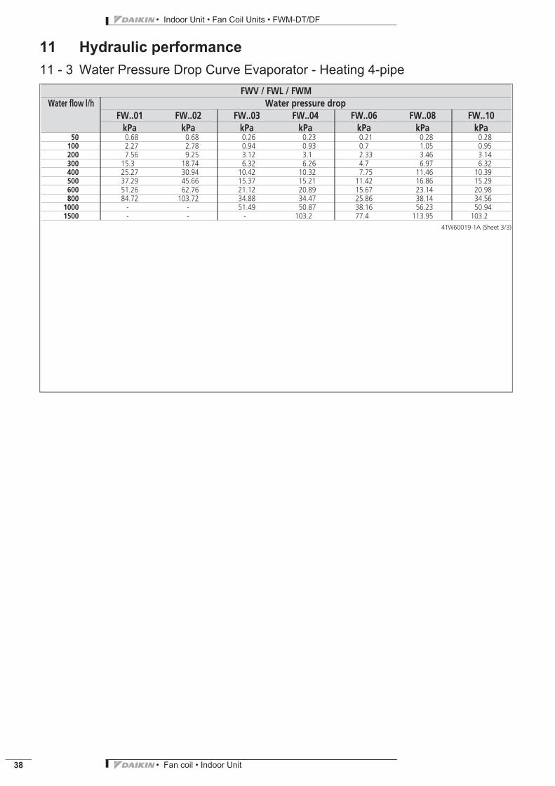
• Indoor Unit • Fan Coil Units • FWM-DT/DF
• Fan coil • Indoor Unit38
11 Hydraulic performance11 - 3 Water Pressure Drop Curve Evaporator - Heating 4-pipe
FWV / FWL / FWMWater flow l/h Water pressure drop
FW..01 FW..02 FW..03 FW..04 FW..06 FW..08 FW..10kPa kPa kPa kPa kPa kPa kPa
50 0.68 0.68 0.26 0.23 0.21 0.28 0.28100 2.27 2.78 0.94 0.93 0.7 1.05 0.95200 7.56 9.25 3.12 3.1 2.33 3.46 3.14300 15.3 18.74 6.32 6.26 4.7 6.97 6.32400 25.27 30.94 10.42 10.32 7.75 11.46 10.39500 37.29 45.66 15.37 15.21 11.42 16.86 15.29600 51.26 62.76 21.12 20.89 15.67 23.14 20.98800 84.72 103.72 34.88 34.47 25.86 38.14 34.56
1000 - - 51.49 50.87 38.16 56.23 50.941500 - - - 103.2 77.4 113.95 103.2
4TW60019-1A (Sheet 3/3)

Naamloze Vennootschap - Zandvoordestraat 300, B-8400 Oostende - Belgium - www.daikin.eu - BE 0412 120 336 - RPR Oostende EC
DE
N1
0-4
00
• C
D •
08
/10
• C
op
yri
gh
t D
aik
in
Th
e p
rese
nt
pu
blic
ati
on
su
pe
rse
de
s E
CD
EN
09
-40
0
Pre
par
ed
in B
elg
ium
by
Lan
no
o (
ww
w.la
nn
oo
pri
nt.
be
), a
com
pan
y w
ho
se c
on
cern
for
the
en
viro
nm
en
t is
se
t in
th
e E
MA
S an
d IS
O 1
40
01
sys
tem
s.
Re
spo
nsi
ble
Ed
ito
r: D
aik
in E
uro
pe
N.V
., Z
an
dv
oo
rde
stra
at
30
0,
B-8
40
0 O
ost
en
de
Daikin products are distributed by:
Daikin’s unique position as a manufacturer of air
conditioning equipment, compressors and refrigerants
has led to its close involvement in environmental issues.
For several years Daikin has had the intention to become
a leader in the provision of products that have limited
impact on the environment. This challenge demands the
eco design and development of a wide range of products
and an energy management system, resulting in energy
conservation and a reduction of waste.
Daikin Europe N.V. is participating in the EUROVENT
Certification Programme. Products are as listed in the
EUROVENT Directory of Certified Products.
The present publication is drawn up by way of information only and does not constitute an offer binding
upon Daikin Europe N.V.. Daikin Europe N.V. has compiled the content of this publication to the best of its
knowledge. No express or implied warranty is given for the completeness, accuracy, reliability or fitness for
particular purpose of its content and the products and services presented therein. Specifications are subject
to change without prior notice. Daikin Europe N.V. explicitly rejects any liability for any direct or indirect
damage, in the broadest sense, arising from or related to the use and/or interpretation of this publication. All
content is copyrighted by Daikin Europe N.V..


