Fan-Air Operations & Maintenance Manual
12
Fan-Air ® Evaporative Cooler O&M Manual 1920 E Broadway Road Tempe, AZ 85282 T: 480.968.9550 F: 480.968.9555 E: [email protected] www.unitedmetal.com Information subject to change without notice. Fan-Air O&M (Rev. Dec. 2014) PART NO. 59284 NOTE! READ AND SAVE THIS MANUAL — IMPORTANT SAFETY INSTRUCTIONS USE AND CARE INFORMATION FOR UNITED METAL PRODUCTS Fan-Air ® EVAPORATIVE COOLERS The selection of evaporative cooling as a method of cooling your building will provide maximum cooling at minimum operating expense. Your evaporative cooler unit is designed and built to provide many years of dependable operation. The following information includes sections on installation, start-up and regular maintenance. NOTE: If any assistance from the factory is needed to check, test, or start-up any UMP equipment, a prevalent rate per day, per person plus travel, lodging, food, etc., will be paid by the buyer/contractor. INSTALLATION AND START-UP SAFETY • An evaporative cooler should only be installed by a qualified and experienced installer in which all work should be in compliance to all local and national building and electrical codes. • Before installation it is important to be certain the mounting surface will bear the operating weight of the unit and is secured to the building structure in accordance with local and national codes. The unit must also be secured to the mounting surface in accordance with local and national codes. • For proper unit operation it is also important that it be operated in a completely level position. • Electrical wiring must be installed a safe distance away from any sharp or moving parts (blower wheels, pulleys, sheaves, belts, etc.) and in accordance with the NEC and local codes. • Either an open drip proof or totally enclosed fan cooled motor may be used. Check the electrical supply to see that it matches the requirements shown on the motor name plate. • Guards must be installed when the rotating fan prop or wheel is operating above an occupied space or within 7ft of working area or whenever deemed advisable for safety reasons. • Evaporative media should be wetted-out, dried and reservoir drained, and then repeat process one more time before running for normal operation. • A bleed-off or flush system is required to reduce scale from formation on the evaporative media; prolonging media life. • Before start-up and after servicing and cleaning, all safety devices and panels must be installed and operating. PRE-START CHECK LIST Complete and fax a copy of the enclosed Pre-Start Checklist to United Metal Products within 30 days of start-up to validate the evaporative cooler warranty. For field support and installation assistance, or to obtain a printed copy of these instructions, please contact Customer Service at: T 480-968-9550 F 480-968-9555 [email protected] For future reference, record Model and Serial Numbers from the outside of your evaporative cooler here: Model No.____________________________________ Serial No.____________________________________ SAFETY Caution: DISCONNECT ALL ELECTRICAL POWER TO THE UNIT BEFORE ATTEMPTING TO INSTALL, OPEN, OR SERVICE YOUR UNIT. IF THE UNIT IS THERMOSTATICALLY CONTROLLED, THE THERMOSTAT IS NOT TO BE USED AS A DISCONNECT AS IT MAY RESET AND START THE UNIT UNEXPECTEDLY. WARNING - TO REDUCE THE RISK OF FIRE, ELECTRIC SHOCK, OR INJURY TO PERSONS, OBSERVE THE FOLLOWING: Installation work and electrical wiring must be done by qualified person(s) in accordance with all applicable codes and stan- dards, including fire-rated construction. When cutting or drilling into wall or ceiling, do not damage elec- trical wiring and other hidden utilities.
Transcript of Fan-Air Operations & Maintenance Manual

Fan-Air® Evaporative Cooler O&M Manual
1920 E Broadway Road Tempe, AZ 85282 T: 480.968.9550 F: 480.968.9555 E: [email protected] www.unitedmetal.com Information subject to change without notice. Fan-Air O&M (Rev. Dec. 2014)
PART NO. 59284
NOTE! READ AND SAVE THIS MANUAL — IMPORTANT SAFETY INSTRUCTIONS
USE AND CARE INFORMATION FOR UNITED METAL PRODUCTS Fan-Air® EVAPORATIVE COOLERS
The selection of evaporative cooling as a method of cooling your building will provide maximum cooling at minimum operating expense. Your evaporative cooler unit is designed and built to provide many years of dependable operation. The following information includes sections on installation, start-up and regular maintenance. NOTE: If any assistance from the factory is needed to check, test, or start-up any UMP equipment, a prevalent rate per day, per person plus travel, lodging, food, etc., will be paid by the buyer/contractor.
INSTALLATION AND START-UP SAFETY• An evaporative cooler should only be installed by a qualified and experienced installer in which all work should be in compliance to all local and national building and electrical codes.• Before installation it is important to be certain the mounting surface will bear the operating weight of the unit and is secured to the building structure in accordance with local and national codes. The unit must also be secured to the mounting surface in accordance with local and national codes.• For proper unit operation it is also important that it be operated in a completely level position.• Electrical wiring must be installed a safe distance away from any sharp or moving parts (blower wheels, pulleys, sheaves, belts, etc.) and in accordance with the NEC and local codes.• Either an open drip proof or totally enclosed fan cooled motor may be used. Check the electrical supply to see that it matches the requirements shown on the motor name plate.• Guards must be installed when the rotating fan prop or wheel is operating above an occupied space or within 7ft of working area or whenever deemed advisable for safety reasons.• Evaporative media should be wetted-out, dried and reservoir drained, and then repeat process one more time before running for normal operation.• A bleed-off or flush system is required to reduce scale from formation on the evaporative media; prolonging media life.• Before start-up and after servicing and cleaning, all safety devices and panels must be installed and operating.
PRE-START CHECK LIST Complete and fax a copy of the enclosed Pre-Start Checklist to United Metal Products within 30 days of start-up to validate the evaporative cooler warranty.
For field support and installation assistance, or to obtain a printed copy of these instructions, please contact Customer Service at:T 480-968-9550 F [email protected]
For future reference, record Model and Serial Numbers from the outside of your evaporative cooler here:
Model No.____________________________________
Serial No.____________________________________
SAFETY Caution: DISCONNECT ALL ELECTRICAL POWER TO THE UNIT BEFORE ATTEMPTING TO INSTALL, OPEN, OR SERVICE YOUR UNIT. IF THE UNIT IS THERMOSTATICALLY CONTROLLED, THE THERMOSTAT IS NOT TO BE USED AS
A DISCONNECT AS IT MAY RESET AND START THE UNIT UNEXPECTEDLY.
WARNING - TO REDUCE THE RISK OF FIRE, ELECTRIC SHOCK, OR INJURY TO PERSONS, OBSERVE THE FOLLOWING:
Installation work and electrical wiring must be done by qualified person(s) in accordance with all applicable codes and stan-dards, including fire-rated construction.
When cutting or drilling into wall or ceiling, do not damage elec-trical wiring and other hidden utilities.
1920 E Broadway Road Tempe, AZ 85282 T: 480.968.9550 F: 480.968.9555 E: [email protected] www.unitedmetal.com Information subject to change without notice. Fan-Air O&M (Rev. Dec. 2014)
START-UP PROCEDURE RECEIVING
Inspect the complete unit for shipping damage. If damage is present, you have the right to either accept or reject the ship-ment. If the receiving contractor or the receiving agent or the contractor elects to receive the equipment in a damaged con-dition, it then becomes the contractor’s responsibility to note the extent of the damage on the delivering freight bill of lading in the presence of the delivering agent (driver) of the deliver-ing freight carrier in accordance with the ICC regulations. It also then becomes the responsibility of the receiving contrac-tor to work with the delivering carrier to have the equipment repaired to the satisfaction of United Metal Products, Inc., so the warranty may remain valid. United Metal Products must also be notified of shipping damage immediately. Be sure to read the warranty for further information. United Metal Products will in no way be responsible for any unauthorized back charges due to events or circumstances out of their control which may cause shipping delays.
INSPECTION OF EQUIPMENT-VISUAL
The equipment type and arrangement should be verified as ordered at once when it arrives at the jobsite. When a discrepancy is found, the local United Metal Products Sales Representative must be notified immediately so that corrective action may be investigated, also verify electrical conformance to specifications. Unauthorized alterations and unauthorized back charges will not be recognized by United Metal Products, Inc.
LONG-TERM STORAGE
There is a time limit of one year from date of shipment that any unit may be kept in long-term storage. At the end of the one year period, the unit must be in operation. Rotate the wheel by hand every two weeks to redistribute grease on internal bearing parts.NOTE: Failure to perform the long-term storage requirements past 60 days from shipment and properly log these required procedures will void the warranty.
When installing the curb, obtain a copy of the approved sub-mittal, as each unit and actual curb installation may not be identical. Do not use this typical curb installation detail (Figure A) to install your curb.
NOTE: The curb may be shipped unassembled. It may be nec-essary to assemble it on the jobsite. Each part of the curb is identified with the proper tags and/or markings. It is important the curb be installed level and square.
NOTE: See section under receiving instructions when receiv-ing curbs and inspecting for freight damage and filing of freight damage claims. Any freight damage is the responsibil-ity of the receiving contractor and/or his authorized receiving agent and the delivering carrier.
NOTE: Should there be any questions as to the number of pieces or curb parts or assembling of the curb, contact United Metal Products at once.
NOTE: Units and curbs must be attached to the building struc-ture in accordance with local and national codes.
INSTALLATION AND START-UP SAFETY• Before installation it is important to be certain the mounting surface will bear the operating weight of the unit. For proper unit operation, it is also important that it be operated in a completely level position.• Electrical wiring must be installed a safe distance away from any sharp or moving parts (blower wheels, pulleys, sheaves, belts, etc.).• All guards and/or interlocks, mechanical or electrical, pro-vided by manufacturer must always remain in place to provide needed protection against moving parts.
• Guards must be installed when the rotating fan prop or wheel is operating above an occupied space or within 7ft of working area or whenever deemed advisable for safety rea-sons.• All safety devices, panels, and doors of the unit must be installed and remounted as previously mounted before start-up, servicing, or cleaning.• Do not start-up blower units with no ductwork attached or motor may over-amp and cause damage.• Check for leaks.• Check belt tension.
FIGURE A.
CURB INSTALLATION (Optional)

1920 E Broadway Road Tempe, AZ 85282 T: 480.968.9550 F: 480.968.9555 E: [email protected] www.unitedmetal.com Information subject to change without notice. Fan-Air O&M (Rev. Dec. 2014)
Y N NA FAN / BLOWER1. o o o bearing blocks tight and aligned2. o o o bearing concentrics tight3. o o o driven pulley and hub tight4. o o o remove shipping blocks5. o o o set screws in blower hub tight and secure (NOTE: after two weeks of operation - retighten) MOTOR(S)6. o o o mounting bolts tight7. o o o electrical connections and cover tight8. o o o pulley and hub tight BELTS9. o o o guard in place and secure10. o o o belts are aligned and correctly tensioned WET SECTION11. o o o media clean & in place. Fluted media has the 45° flutes sloping down towards the air entering side12. o o o Connect site water line to cooler float valve. Size = To match float valve. Line pressure = Min. 50 psi / Max. 125 psi.13. o o o fill water reservoir to a level of 2 ½” to 3” or as necessary and set the float to maintain that maximum level not to exceed standpipe14. o o o flush/bleed tubing secure in overflow15. o o o adjust pump flow rate to deliver the required flow evenly over the media16. o o o fill and drain actuators operate properly17. o o o flush and drain the media and sump a mini-mum of twice before operating the cooler (this prevents water carry-over)
Y N NA ELECTRICAL CONNECTIONS18. o o o all electrical connections tight19. o o oprove out door safety switches (where fitted) CABINET20. o o o remove isolator tie downs if provided21. o o o tighten any bolts or screws that may be loose22. o o o the cooler is level and secured to building23. o o o check for leaks24. o o o all safety devices, panels and doors of unit must be installed before start-up, and rein- stalled after servicing or cleaning. OPERATION25. o o o amps26. o o o fan / blower noise27. o o o rotation correct28. o o o air capacity & external static pressure29. o o o vibration30. o o o all safety devices installed and secure31. o o o thermal overloads set properly
COMMISSIONING RECORDSUPPLY FAN AMPS VOLTS A. L1__________ L2__________ L3__________ L1 - L2 __________ L1 - L3 __________ L3 - L2 ________ B. L1__________ L2__________ L3__________ L1 - L2 __________ L1 - L3 __________ L3 - L2 ________ Final Overload Setting__________ Nameplate: Model #__________ Volts________ Amps________ HP________
PUMPS A. L1__________ L2__________ L3__________ L1 - L2 __________ L1 - L3 __________ L3 - L2 ________ B. L1__________ L2__________ L3__________ L1 - L2 __________ L1 - L3 __________ L3 - L2 ________ Nameplate: Model #__________ Volts________ Amps________ HP________
oVerify all Amp and Volt readings meet nameplate data
Installer’s Acceptance Signature X DateNOTES:
PRE-START CHECKLIST(RESPONSIBILITY OF INSTALLING CONTRACTOR)
NOTE: Please complete & return fax to United Metal Products within 30 days of
start-up for warranty validation.Fax: 480-968-9555
INSTALLER ____________________________ COMPANY _____________________________ DATE _______________MODEL NUMBER ________________________ SERIAL NUMBER ________________________ TAG NUMBER _________
WARNING:If the cooler is not installed on a flat and level surface the fan may become out of alignment. Before applying power to the motor for the first time, rotate the fan/blower by hand and check that the blade tip clearance is the same at all points around the fan discharge. Make any adjustments necessary to ensure that the fan is centered and free to rotate.
For field support and installationassistance please call or Email:
Tel: 480-968-9550Email: [email protected]
1920 E Broadway Road Tempe, AZ 85282 T: 480.968.9550 F: 480.968.9555 E: [email protected] www.unitedmetal.com Information subject to change without notice. Fan-Air O&M (Rev. Dec. 2014)
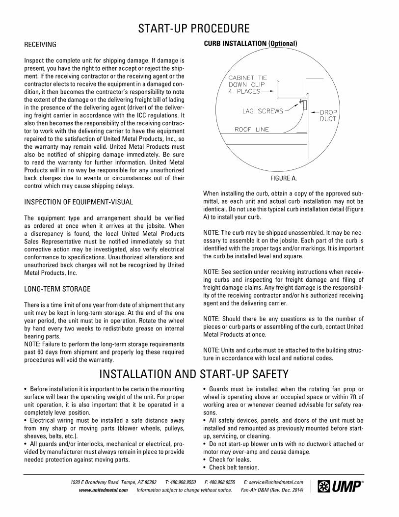
1.0 FLUTED EVAPORATIVE COOLER MEDIA.This section is for evaporative coolers fitted with either 8” or 12” deep cross fluted media. Pads should be checked for salt build-up at beginning and end of season. Scale build-up can occur when heavy salt-laden water is not diluted correctly. If pads scale and are plugged, they should be hosed down to clean away dirt and salt particles.
If the pads become too blocked the cooling efficiency and air delivery will be reduced and the pads should be replaced. The media can be replaced by removing the outer access panels and the internal media cover plate, and then sliding the media along the bottom drain rack. The inlet louver panels may also
be removed to help with this task if necessary. The media can be withdrawn from either side of the cooler. When replacing media, be sure that the 45 degree angled flutes are slanted downward toward the entering air stream (Figure 1.1)
RECOMMENDED FLUTED MEDIA REPLACEMENT SIZES
MODEL SIZE (WxDxH) QUANTITYUMP-639S 12 x 8 x 39 5UMP-644S 12 x 8 x 44 5UMP-639x2S 12 x 8 x 39 9UMP-644x2S 12 x 8 x 44 9UMP-724 12 x 8 x 24 10UMP-730 12 x 8 x 30 10UMP-739 12 x 8 x 39 10UMP-739 XL 12 x 8 x 39 15UMP-751 12 x 8 x 51 10UMP-751 XL 12 x 8 x 51 15UMP-824 U, S or D 12 x 8 x 24 or 12 x 12 x 24 5UMP-839 U, S or D 12 x 8 x 39 or 12 x 12 x 39 5UMP-939 U, S or D 12 x 8 x 39 or 12 x 12 x 39 10UMP-951 U, S or D 12 x 8 x 51 or 12 x 12 x 51 10 NOTE: If unit is supplied with U.L. Class 2 media, remove and replace with same.
REGULAR MAINTENANCE AND ANNUAL START-UPThe commercial / industrial evaporative cooling unit you selected may be either horizontal discharge, down dis-charge or up discharge. The down discharge unit is designed for either flat or pitched roofs. The side discharge unit is designed for either the side of a building or on a flat or pitched roof. The up discharge unit is primarily designed for ground mount application. In all applications, care must be taken that the fan or blower is facing an unoccupied space only. Guards must be installed when the rotating fan prop or wheel is oper-ating above an occupied space or within 7ft of working area or whenever deemed advisable for safety reasons. For units fitted with GFCI, press TEST / RESET buttons to assure proper operation on a monthly basis.
SAFETYCaution: DISCONNECT ALL ELECTRICAL POWER TO THE UNIT BEFORE ATTEMPTING TO INSTALL, OPEN, OR SERVICE YOUR UNIT. IF THE UNIT IS THERMOSTATICALLY CONTROLLED, THE THERMOSTAT IS NOT
TO BE USED AS A DISCONNECT AS IT MAY RESET AND START THE UNIT UNEXPECTEDLY.
For efficient operation it is crucial that your evaporative cool-er be properly maintained each year. The cooling capability of any cooler will be severely limited if regular maintenance is neglected for even one year. Therefore, the following main-tenance information must be applied at the recommended intervals in order to receive maximum benefit from the cooler.
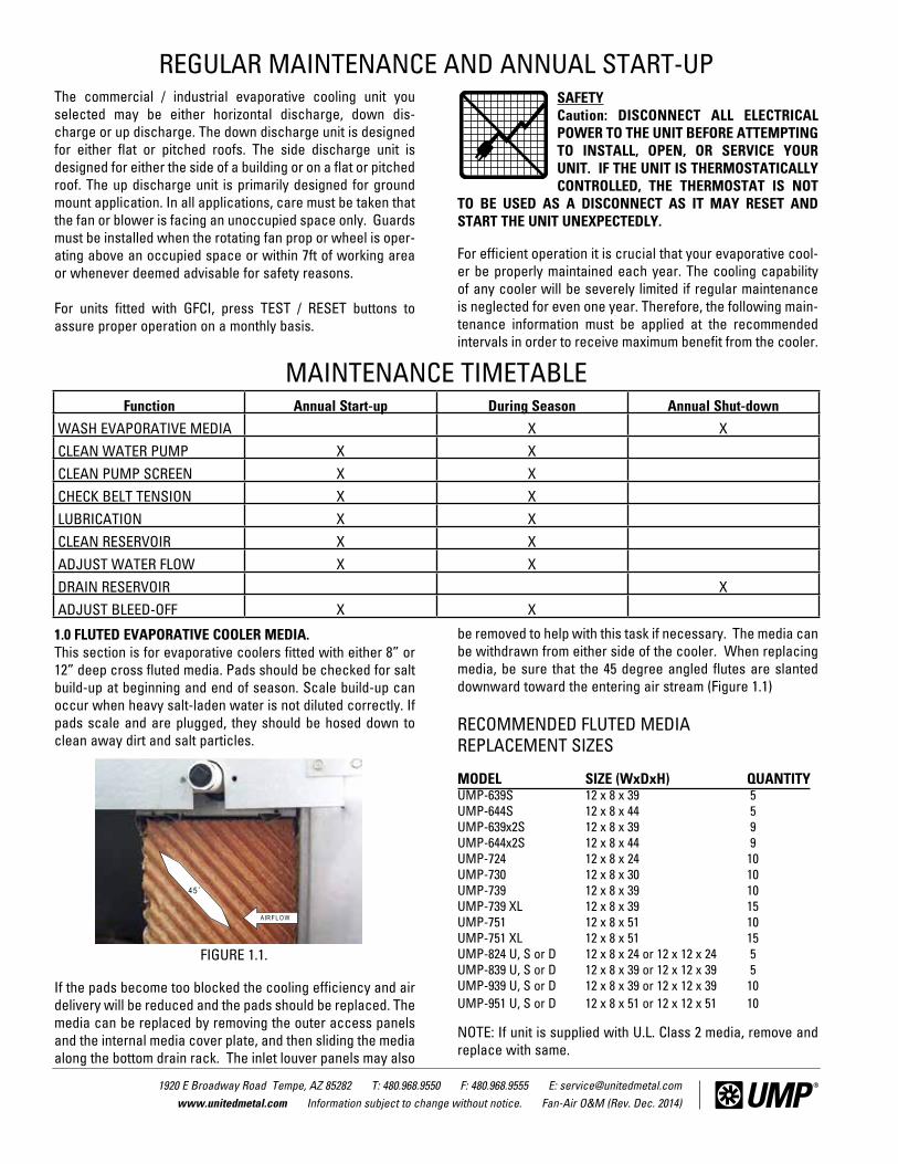
MAINTENANCE TIMETABLEFunction Annual Start-up During Season Annual Shut-down
WASH EVAPORATIVE MEDIA X X CLEAN WATER PUMP X X CLEAN PUMP SCREEN X X CHECK BELT TENSION X X LUBRICATION X X CLEAN RESERVOIR X X ADJUST WATER FLOW X X DRAIN RESERVOIR X ADJUST BLEED-OFF X X
45˚
AIR F L O W
FIGURE 1.1.

1920 E Broadway Road Tempe, AZ 85282 T: 480.968.9550 F: 480.968.9555 E: [email protected] www.unitedmetal.com Information subject to change without notice. Fan-Air O&M (Rev. Dec. 2014)
2.0. INSTALLING OVERFLOW STANDPIPESlide rubber washer over drain bushing, push drain bushing through bottom of cooler, and tighten nut. Screw plastic overflow standpipe into drain bushing and tighten snugly to prevent leakage. On cooler with an auxiliary drain, plug this bushing unless you are utilizing the optional freeze protection or distributor flush system. Connect drain line to drain bushing (standard 3/4”-11.5 Hose coupling threads) or ¾” NPT female connector (where provided) and drain in accordance to local codes.
3.0. WATER BLEED-OFF SYSTEMA water bleed-off or flush system is essential in order to fight scale build-up, prevent excessive salts and corrosion build-up, and prolong the life of the unit. Throughout the life of the evaporative cooler pads, adjust the amount of bleed-off during regular maintenance to maintain the pH of the water between 6 and 8.
For coolers equipped with a manual bleed system, adjust the flow rate while the pump is working and discharge the bleed water directly into the overflow standpipe.
For coolers equipped with an automatic distributor flush system, the timer can be adjusted to increase/decrease the length of time the flush valve is open as well as the period of time between flush cycles. The timer is wired in series with the pump and is only energized when the pump is operating. This allows the cooler to perform the flush cycle based on the number of actual operating hours. The flush valve should be dismantled and cleaned out each season to ensure it does not become blocked.
4.0. WATER DISTRIBUTOR CLEAN-OUTIf distribution pipe or orifice becomes clogged, it should be cleaned out. Evaporative coolers with fluted pad media have a removable plug at the end of each water distributor to allow for proper cleaning of the water distribution pipe (Figure 4.0). Cleaning can generally be achieved by removing the distribu-tor end cap and running the pump. If the contamination is not cleared with this method, high pressure water and/or a dis-
tributor cleaning rod may be used. For a visual inspection and manual cleanout of the water distributor, the whole distributor pipe can be withdrawn from one side of the cooler (Figure 4.1)
Remove the access panel and roof edge cover below the dis-tributor. Remove the inside hose from the end of the distribu-tor pipe and the pipe support that attaches to the cooler roof. To make re-assembly easier, we recommend that both distrib-utor end caps are removed at this point and a 1/2” diameter x 6ft long rod or dowel is pushed into the distributor. Secure the end of the dowel at the end opposite to where the distributor will be removed so that it stays within the cooler when the distributor pipe is removed. Take hold of the distributor pipe where the hose was attached and rotate it down so that it is vertical (this will break the seal at the opposite end of the dis-tributor pipe) and then pull the complete pipe horizontally out of the cooler (without removing the dowel) (Figure 4.2). Clean out the distributor.
Apply a small amount of watertight lubricant (such as AquaShield or AquaLube waterproof lithium based grease) to the first inch of the outside of the distributor pipe and insert it over the dowel and into the cooler (Figure 4.3). The dowel will help to re-locate the “T” fitting at the other end of the distrib-utor assembly. When the distributor pipe is correctly mated
FIGURE 4.0.
FIGURE 4.1.

1920 E Broadway Road Tempe, AZ 85282 T: 480.968.9550 F: 480.968.9555 E: [email protected] www.unitedmetal.com Information subject to change without notice. Fan-Air O&M (Rev. Dec. 2014)
with the “T” fitting the distributor pipe can be rotated back to its original position. Re-attach the distributor pipe support and the flexible hose. Remove the dowel and re-insert the distributor end caps. Note: Distributor pipes in multi-inlet coolers are made right hand and left hand. When re-inserting the distributor pipes make sure the distributor holes will be facing UP when it is rotated to its final position.
5.0. CLEANING THE WATER PUMP AND RESERVOIRALWAYS DISCONNECT POWER BEFORE SERVICING PUMP.Snap the plastic grid off the bottom of the pump and clean. A removable media frame has been provided in fluted pad type coolers (Figure 5.0). Remove old debris from the reservoir. We recommend coating painted galvanized steel reservoirs with high quality sub-sealer after the first year of operation and as needed.
6.0. SETTING THE WATER FLOW RATEAdjust the water flow over the evaporative media pads by the in-line valve (where provided) on each unit. The recommend-ed maximum flow rate is 1.5 GPM per sq. ft. over the top of the pad. (Figure 6.0)
7.0. ASPEN EVAPORATIVE PAD MEDIAThis section is for evaporative coolers fitted with Aspen typecooling media. It is advisable to change the aspen pads twice
during the cooling season-in the beginning of the season andhalf way through it. Only a high quality pad should be installed.A poorly packed pad with air gaps in it will deliver warm airand draw water droplets into the system. On all fan coolers aspun glass air filter must be installed on the inside betweenthe Aspen and wire retainer rack (see Figure 7.2.C).
Replace pads and filter screen as follows:
A. Remove pad frame from cabinet by lifting from the bottomedge and pulling outward and then letting it drop (Figure 7.2.A).B. Remove wire retainer and discard old pad(s) and filter.C. Wash dirt and scale from pad frame with a mild detergentif necessary.D. Lay the new pad in the frame starting at the trough or top end. Tuck pad under trough (toward outside surface of the pad (Figure 7.2.B). Tuck edges inside the frame all the way around, making sure there are no air gaps. It is important to do this step correctly to avoid water spray problems.E. Lay the spun filter on top of the pads. Reinstall the wire rack-apply pressure to push sharp pointsinto the pad (Figure 7.2.C).
FIGURE 5.0.
FIGURE 6.0.
FIGURE 4.2.
FIGURE 4.3.

1920 E Broadway Road Tempe, AZ 85282 T: 480.968.9550 F: 480.968.9555 E: [email protected] www.unitedmetal.com Information subject to change without notice. Fan-Air O&M (Rev. Dec. 2014)
RECOMMENDED ASPEN PAD REPLACEMENT SIZES
MODEL SIZE (W x H) QUANTITYUD2140L, UMP-536 30 x 36 8UD3640L 30 x 36 10US2140, UMP-454S, UMP-554S 28 x 56 6S3680 28 x 56 7UD2140, UMP-454D, UMP-554D 28 x 56 8UD3640, D3680 28 x 56 10 NOTE: If unit is supplied with U.L. Class 2 media, remove and replace with same.
8.0. BELT TENSION AND ALIGNMENTWith each cooler inspection be sure to check for proper belt tension and alignment. Important: When assembling the motor and drive, the sheaves must be aligned to keep the belt straight. This is accom-plished by ensuring that the motor and fan sheave grooves are directly in line with one another.
Proper belt tension is approximately ½” movement of the belt when pressed at mid-span under normal thumb pressure. Do not over tighten belt. However, a new belt should be tighter than a used belt. (FIGURE 8.1)
9.0. BEARING LUBRICATIONBall bearings pillow blocks (Fan) - Suggested initial greasing interval (6 Months). Adjust lubrication frequency depending hours of operation, temperature, and surrounding condition that will affect the relubrication frequency required. Lubricate the bearings prior to extended shutdown or storage and rotate shaft monthly to aid corrosion protection. Caution: Do not over grease. The major cause of premature bearing failure is over greasing. Type of Grease: Lubricate with a high quality NLGI No. 2 or 3 multipurpose ball bearing grease having rust inhibitors and antioxidant additives. Recommended grease: Shell - Alvania No. 2, Gulf - Gulfcrown No. 2, Mobil - Mobilith AW2/Mobilith SHC100 and American - Rykon Premium 2.
Motor bearing grease will lose its lubricating ability over time, not suddenly. Good results can be obtained if the following recommendations are used in your maintenance program. Type of Grease: A high grade ball bearing grease should be used. Recommended grease for standard service conditions is Polyrex EM (Exxon Mobil). Equivalent and compatible greases include: Texaco Polystar, Rykon Premium # 2 and Chevron SRI. Lubrication Intervals: these recommended intervals are based on average use. NEMA Frame size up to 210 - 6000 hours, NEMA Frame 210 to 280 - 4750 hours.
10.0. FAN AND BLOWER ASSEMBLIESWhether the evaporative cooler is fitted with a propeller fan or a blower fan, correct set-up and maintenance is required.
SAFETY NOTE: GUARDS MUST BE INSTALLED WHEN THE ROTATING FAN PROP OR WHEEL IS OPERATING ABOVE AN OCCUPIED SPACE OR WITHIN 7FT OF WORKING AREA OR WHENEVER DEEMED ADVISABLE FOR SAFETY REASONS.
FIGURE 7.2.B.
FIGURE 7.2.C
FIGURE 7.2.A.
FIGURE 8.1 - Belt Tension - Propeller Fan Coolers Shown
1920 E Broadway Road Tempe, AZ 85282 T: 480.968.9550 F: 480.968.9555 E: [email protected] www.unitedmetal.com Information subject to change without notice. Fan-Air O&M (Rev. Dec. 2014)
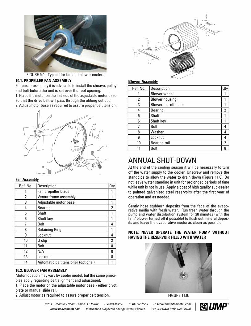
10.1. PROPELLER FAN ASSEMBLYFor easier assembly it is advisable to install the sheave, pulley and belt before the unit is set over the roof opening.1. Place the motor on the flat side of the adjustable motor base so that the drive belt will pass through the oblong cut out. 2. Adjust motor base as required to assure proper belt tension.
Fan Assembly
10.2. BLOWER FAN ASSEMBLYMotor location may vary by cooler model, but the same princi-ples apply regarding belt alignment and adjustment.1. Place the motor on the adjustable motor base - either pivot plate or manual slide rail. 2. Adjust motor as required to assure proper belt tension.
Blower Assembly
ANNUAL SHUT-DOWNAt the end of the cooling season it will be necessary to turn off the water supply to the cooler. Unscrew and remove the standpipe to allow the water to drain down (Figure 11.0). Do not leave water standing in unit for prolonged periods of time while unit is not in use. Apply a coat of high quality sub-sealer to painted galvanized steel reservoirs after the first year of operation and as needed.
Gently hose stubborn deposits from the face of the evapo-rative media with fresh water. Run fresh water through the pump and water distribution system for 30 minutes (with the fan / blower turned off if possible) to flush out mineral depos-its and leave the evaporative media as clean as possible.
NOTE: NEVER OPERATE THE WATER PUMP WITHOUT HAVING THE RESERVOIR FILLED WITH WATER
Ref. No. Description Qty1 Blower wheel 12 Blower housing 13 Blower cut-off plate 14 Bearing 25 Shaft 16 Shaft key 17 Bolt 48 Washer 49 Locknut 410 Bearing rail 211 Bolt 8
FIGURE 9.0 - Typical for fan and blower coolers
Ref. No. Description Qty1 Fan propeller blade 12 Venturiframe assembly 13 Adjustable motor base 14 Bearing 25 Shaft 16 Shaft key 17 Bolt 48 Retaining Ring 19 Locknut 410 U clip 211 Bolt 812 N/A 013 Locknut 814 Automatic belt tensioner (optional) 1
FIGURE 11.0.

1920 E Broadway Road Tempe, AZ 85282 T: 480.968.9550 F: 480.968.9555 E: [email protected] www.unitedmetal.com Information subject to change without notice. Fan-Air O&M (Rev. Dec. 2014)
All units come supplied with pre-wired weather tight electricenclosure mounted on the inside of the unit. When wiring theunit from the factory installed electrical box to the outside of the unit, ALL grounding, wiring and materials must be installedin accordance with all current N.E.C. and local codes, and must be performed by a qualified licensed technician. Consultthe chart below for proper wire, circuit breaker and fuseableswitch. CAUTION: Improper wiring, installation or mainte-nance of equipment may cause electric shock, fire or injury topersons.
SAFETYCaution: DISCONNECT ALL ELECTRICAL POWER TO THE UNIT BEFORE ATTEMPTINGTO INSTALL, OPEN, OR SERVICE YOUR UNIT.IF THE UNIT IS THERMOSTATICALLY CONTROLLED, THE THERMOSTAT IS NOT TO
BE USED AS A DISCONNECT AS IT MAY RESET AND START THE UNIT UNEXPECTEDLY.
Caution: Do not exceed the maximum amperage output as stamped on the motor specification plate or motor can over load. Only qualified persons with proper electrical equip-mentand knowledge should adjust variable pitch sheaves. Do not allow water to get in the motor.
Caution: Disconnect all the electrical power to the unit and insure that belt is not rotating before adjusting belt tension. Do not adjust belt tension by changing diameter of adjustable sheave. Adjust belt tension only by adjusting motor bracket.
Even while routinely inspecting or servicing the inside, the unit can be accidentally started. Keep children and pets away from the unit and electrical supply when you are working on it.
Do not attempt to perform any part of the installation described in this booklet unless you are FULLY QUALIFIED to do so. All electrical work must meet local codes and must beperformed by qualified personnel only.
WIRING INSTRUCTIONS
THREE PHASE MOTOR DATA.P.HROTOM
MPR0081.zH06ROF)EngiseDnon(SROTOMEGACLERRIUQSDRADNATS 51 01 7 5 3 2 1 1
SPMA—)CEN(TNERRUCDAOLLLUF .EZIS–WHHX,NWHT–NHHT,WHT)57(–EZISERIWREPPOCMUMINIM
3.846
2.238
3.5201
5.7121
0.1141
8.741
9.641
8.441
7.341
5.241 ROTOM
METSYS
002)802(
STLOV
TIUCRICREKAERB
.SPMA—GNITARPIRTREKAERBCITENGAM-LAMREHT)ylnorekaerb(.ON.TAC–REKAERBLAIRTSUDNI
0909023LAF
0606023LAF
0505023LAF
5353023LAF
0202023LAF
5151023LAF
5151023LAF
5151023LAF
5151023LAF
5151023LAF
ELBISUFHCTIWS
.ON.TAC–.LCNE1AMEN–HCTIWSYTUDYVAEH.SPMA—ESUFYALEDEMITTNEMELELAUDHTIW
N223H06
N223H05
N223H04
N123H52
N123H5.71
N123H01
N123H01
N123H8
N123H52.6
N123H4
CITENGAMRETRATS
EPYT6358SSALC—.LCNE1AMEN.ON—STINULAMREHTYOLLAGNITLEMEERHTHTIW
1-GES6.47CC
1-GDS65B
3-GCS54B
3-GCS0.82B
2-GBS5.51B
2-GBS5.11B
21-GAS2.01B
21-GAS09.6B
21-GAS58.4B
21-GAS03.3B
.SPMA—)CEN(TNERRUCDAOLLLUFEZIS–WHHX,NWHT–NHHT,WHT)57(–EZISERIWREPPOCMUMINIM
246
8201
2201
2.5141
6.941
8.641
0.641
2.441
2.341
2.241 ROTOM
METSYS
032)042(
STLOV
TIUCRICREKAERB
.SPMA—GNITARPIRTREKAERBCITENGAM-LAMREHT)ylnorekaerb(.ON.TAC–REKAERBLAIRTSUDNI
0808023LAF
0606023LAF
5454023LAF
0303023LAF
0202023LAF
5151023LAF
5151023LAF
5151023LAF
5151023LAF
5151023LAF
ELBISUFHCTIWS
.ON.TAC–.LCNE1AMEN–HCTIWSYTUDYVAEH.SPMA—ESUFYALEDEMITTNEMELELAUDHTIW
N223H06
N223H04
N123H03
N123H52
N123H51
N123H01
N123H01
N123H8
N123H6.5
N123H4
CITENGAMRETRATS
EPYT6358SSALC—.LCNE1AMEN.ON—STINULAMREHTYOLLAGNITLEMEERHTHTIW
1-GDS97B
1-GDS54B
3-GCS63B
3-GCS52B
2-GBS41B
2-GBS2.01B
21-GAS01.9B
21-GAS52.6B
21-GAS51.4B
21-GAS03.3B
SPMA—)CEN(TNERRUCDAOLLLUFEZIS–WHHX,NWHT–NHHT,WHT)57(–EZISERIWREPPOCMUMINIM
1201
4141
1141
6.741
8.441
4.341
0.341
1.241
6.141
1.141 ROTOM
METSYS
064)084(
STLOV
TIUCRICREKAERB
.SPMA—GNITARPIRTREKAERBCITENGAM-LAMREHT)ylnorekaerb(.ON.TAC–REKAERBLAIRTSUDNI
0404043LAF
5252043LAF
0202043LAF
5151043LAF
5151043LAF
5151043LAF
5151043LAF
5151043LAF
5151043LAF
5151043LAF
ELBISUFHCTIWS
.ON.TAC–.LCNE1AMEN–HCTIWSYTUDYVAEH.SPMA—ESUFYALEDEMITTNEMELELAUDHTIW
163H03
163H02
163H02
163H51
163H8
163H52.6
163H6.5
163H4
163H2.3
163H2
CITENGAMRETRATS
EPYT6358SSALC—.LCNE1AMEN.ON—STINULAMREHTYOLLAGNITLEMEERHTHTIW
1-GDS23B
3-GCS52B
3-GCS5.71B
2-GBS5.11B
2-GBS09.6B
21-GAS58.4B
21-GAS51.4B
21-GAS00.3B
21-GAS04.2B
21-GAS54.1B
.SPMA—)CEN(TNERRUCDAOLLLUFEZIS–WHHX,NWHT–NHHT,WHT)57(–EZISERIWREPPOCMUMINIM
7121
1141
0.941
1.641
9.341
7.241
4.241
7.141
3.141
9.041 ROTOM
METSYS
575)006(
STLOV
TIUCRICREKAERB
.SPMA—GNITARPIRTREKAERBCITENGAM-LAMREHT)ylnorekaerb(.ON.TAC–REKAERBLAIRTSUDNI
5353063LAF
0202063LAF
5151063LAF
5151063LAF
5151063LAF
5151063LAF
5151063LAF
5151063LAF
5151063LAF
5151063LAF
ELBISUFHCTIWS
.ON.TAC–.LCNE1AMEN–HCTIWSYTUDYVAEH.SPMA—ESUFYALEDEMITTNEMELELAUDHTIW
163H52
163H02
163H51
163H01
163H52.6
163H5
163H4
163H2.3
163H5.2
163H8.1
CITENGAMRETRATS
EPYT6358SSALC—.LCNE1AMEN.ON—STINULAMREHTYOLLAGNITLEMEERHTHTIW
1-GDS52B
3-GCS5.71B
3-GCS8.21B
2-GBS01.9B
2-GBS58.4B
21-GAS07.3B
21-GAS03.3B
21-GAS04.2B
21-GAS88.1B
21-GAS03.1B
Full load currents. wire sizes, and switch sizes are based on 1990 NEC. Fuse sizes and circuit breaker trip amperesare appropriate selections, suitable for most installations. Thermal unit selections are not based on NEC currents (seeNEC 430-6), but are selected from average full load currents. Thermal units can be more accurately selected usingtable furnished with starter and full load current marked on motor nameplate.

1920 E Broadway Road Tempe, AZ 85282 T: 480.968.9550 F: 480.968.9555 E: [email protected] www.unitedmetal.com Information subject to change without notice. Fan-Air O&M (Rev. Dec. 2014)
1. Avoid unnecessary jarring or rough handling.2. Spreader bars must be used to prevent damage to the unit casing.3. Care must be taken to keep the unit in the upright position during rigging.4. Use lifting eyes provided on top of unit.5. Avoid damage to the curb and curb gasket when rigging onto a curb.6. Only used trained professional riggers when moving equipment.
Proper handling of the equipment is mandatory during unload-ing and setting it into position.
NOTE: If equipment is not set in its permanent position and isstored on the ground or other unlevel area, proper provisionsmust be taken for supporting and protecting the equipmenSee Long-Term Storage section on the Start-Up sheet.
It is mandatory that the proper spreader bars and hoisting straps be used when rigging. It is also mandatory that an experienced and reliable rigger be selected to handle unload-ing and final placement of the equipment. Your rigger must beadvised that the unit contains delicate components and that itbe handled in an upright position. Care must be exercised to avoid twisting the structure.
All units and roof curbs must be secured to the building struc-ture in accordance with local and national codes.
When the equipment has been set in final placement, the following must be done:1. Remove any internal shipping blocks.2. Tighten any bolts or screws that may have worked loose during shipment.
RIGGING INSTRUCTIONS
CLEVIS
(4) LIFTING EYES
OPTIONAL FACTORYSUPPLIED CURB
CURB GASKET
SPREADER BAR MUST BELONG ENOUGH TO HOLDHOISTING STRAPS AWAYFROM THE UNIT TO PREVENTDAMAGE TO CABINET

1920 E Broadway Road Tempe, AZ 85282 T: 480.968.9550 F: 480.968.9555 E: [email protected] www.unitedmetal.com Information subject to change without notice. Fan-Air O&M (Rev. Dec. 2014)
SYMPTOM POSSIBLE CAUSES CORRECTIVE ACTION .spag ria esolc ot snoitces sdap evitaropave tsujdA .1 .sdap neewteb spag riA .1 OTNI REVOYRRAC RETAW
drawot detnals setulf delgna °54 htiw aidem llatsnier dna evomeR .2 .sdrawkcab dellatsni aideM .2 MAERTS RIAentering air.
.evaehs rotom elbatsujda ta MPR naf tsujdA .3 .MPR naf evissecxE .3 .lauqe ro aidem EO ytilauq hgih htiw ecalpeR .4 .aidem tnemecalper ytilauq rooP .4
5. Incorrectly sized replacement media. 5. Replace with correct size of media. MPG 5.1 deecxe ton dluohs wolF .tinu no dedivorp evlav enilni tsujdA .6 .wolf retaw evissecxE .6
per sq. ft. of top pad area. .dap ecalper ro esniR .7 .aidem evitaropave deggulP .7
.etar deelb tneiciffus a yfirev dna ,riovreser llif dna niard ,aidem hsaW .8 .retaw nedal tlas yvaeH .8
.ecalpeR .1 .gniraeb evitcefeD .1 ESION EVISSECXE .wercs nethgiT .2 .tfahs no esool ralloc gnikcoL .2 NOITARBIV RO/DNA
3. Foreign material inside sealed bearing. 3. Replace. 4. Sheave not tightened on shaft: (motor or fan / blower). 4. Tighten set screw and check alignment.
.swercs / stlob nethgiT .5 .rewolb / naf esooL .5 .noisnet tsujdA .6 .tleb esooL .6
.ecalper ro naelC .7 .ytrid ro ,ylio ,nrow era stleB .7 .noitceles evird tcerroc rof etalp eman relooc eeS .8 .noitceles evird reporpmI .8
.ngilaeR .9 .sevaehs dengilasiM .9 .ecalper ro nethgiartS .01 .ecnalab fo tuo rewolb / naF .01
11. Motor or motor base not securely anchored. 11. Secure properly. .ecalpeR .21 .tfahs rewolb / naf tneB .21
.sgniraeb rewolb / naf etacirbuL .31 .yrd sgniraeB .3114. Fan / blower wheel rubbing on housing 14. Inspect fan / blower shaft collars, belt, pulley alignment, and motor
mounting. .rekaerb tiucric teser ro esuf ecalpeR .1 .rekaerb tiucric nepo ro esuf nwolB .1 REWOLB / NAF
.ecalpeR .2 .tleb nekorB .2 EVITAREPONI .tnemngila kcehc dna nethgiT .3 .sevaehs esooL .3 .ynapmoc rewop lacol tcatnoC .4 .ffo denrut yticirtcelE .4
.ecalper ro riapeR .5 .rotom evitcefeD .5 .noitalitnev esaercni ot srood ro wodniw nepO .1 .tsuahxe ria tneiciffus fo kcaL .1 TNEICIFFUSNI
.noitanibmoc evird reporp rof kcehC .2 .)MPR( wols oot deeps rewolb / naF .2 WOLF RIA .tnemngila kcehc dna nethgiT .3 .egappils tleB .3
.dap ecalper ro esniR .4 .deggulp aidem gnilooc evitaropavE .4 .revuol naelC .5 .deggulp lenap revuol telnI .5
INADEQUATE COOLING 1. Insufficient water flow to pads, i.e. pads are dry. 1. Check water distribution system. .aidem ecalper ro esniR .2 .elacs htiw deggulp sdaP .2
.wolf erom wolla ot evlav llab enilni nepO .3 .sdap aidem yrD .3 .gnisuoh rellepmi naelC .pmup gulpnU .4 .evitareponi pmuP .4
5. Evaporative media installed backward. 5. Reinstall media pads as shown above .metsys rotubirtsid ecalper ro seloh raelC .6 .deggulp rotubirtsiD .6" ."½ 2 dna 2 neewteb ot level retaw tsujdA .7 .riovreser ni wol oot level retaW .7
.level retaw no nruT .8 .ylppus retaw oN .8 .i.s.p 05 fo muminim ot esaercnI .9 .erusserp retaw woL .9
.noisnet tleb tsujdA .1 .noisnet tleb evissecxE .1 DNA NO SELCYC ROTOM .sgniraeb rewolb / naf etacirbuL .2 .nezorf ro thgit tfahs rewolb / naF .2 FFO
.spma etalp eman ot rotom tsujdA .3 .dedaolrevo rotoM .3 .sezis reporp rof etalp eman gnilooc ot refeR .4 .tinu naf no gnizis yellup reporpmI .4
.taolf tsujdA .1.detsujda ylreporpmi mra taolF .1 MORF GNIPPIRD RETAW.evlav taolf ecalpeR .2.gnikael evlav taolF .2FO EPIPDNATS WOLFREVO
.bruc foor ro dnats eht no tinu eht leveL .3 .gnitnuom levelnU .3 TINU FO RENROCDISAGREEABLE ODOR 1. Evaporative media not completely saturated. 1. Saturate evaporative media before starting unit.
.riovreser naelc dna ,hsulf ,niarD .2.riovreser ni retaw elats ro tnangatS .23. Evaporative media mildewed or clogged. 3. Replace evaporative media.
TROUBLESHOOTING GUIDE

1920 E Broadway Road Tempe, AZ 85282 T: 480.968.9550 F: 480.968.9555 E: [email protected] www.unitedmetal.com Information subject to change without notice. Fan-Air O&M (Rev. Dec. 2014)
WARNINGOur products are designed and manufactured to provide
performance, but they are not guaranteed to be 100% free of defects. Even reliable products will experience occasional failure, and this possibility should be recognized by the user. If these products are used in a life support ventilation system where failure could result in loss or injury, the use should provide adequate back-up ventilation, supplementary natural ventilation or failure alarm system, or acknowledge willingness to accept the risk of such loss or injury.
DO NOT USE IN HAZARDOUS ENVIRONMENTS where fan’s electrical system could provide ignition to combustible or flammable materials.
NOTEIf any assistance from the factory is needed to check,
test, or start-up any UMP equipment, a prevalent rate per day,
per person plus travel, lodging, food, etc., will be paid by the buyer/contractor.
CAUTIONGuards must be installed when fan is within reach of per-
sonnel or within seven (7) feet of working level or when deemed advisable for safety.
DISCLAIMERUnited Metal Products, Inc. had made a diligent effort to
illustrate and describe the products in this literature accurately; however, such illustrations and descriptions are for the sole purpose of identification, and do not express or imply a war-ranty that the products are merchantable, or fit for a particular purpose, or that the products will necessarily conform to the illustrations or descriptions or dimension.
All information in this literature is subject to change without notice.
LIMITED WARRANTYUNITED METAL PRODUCTS, INCORPORATED extends
this limited warranty to the original buyer and warrants that products manufactured by United Metal Products shall be free from original defects in workmanship and materials for 12 months from start-up or 18 months from date of shipment (whichever is sooner), provided same have been properly stored, installed, serviced, maintained and operated with bleed-off system properly installed. This warranty shall not apply to products which have been altered or repaired without United Metal Products’ express authorization, or altered or repaired in any way so as, in United Metal Products’ judgment, to affect its performance or reliability, nor which have been improper-ly installed or subjected to misuse, negligence, or accident, or incorrectly used in combination with other substances. Warranties on purchased parts, such as electric motors, pumps and pads, are limited to the terms of warranty extended by our supplier (usually one year duration).
LIMITATION OF REMEDY AND DAMAGES: All claims under this warranty must be made in writing and delivered to United Metal Products, Inc., 1920 East Broadway Road, Tempe, Arizona 85282, within 15 days after the date of shipment by United Metal Products of the product claimed defective, and buyer shall be barred from any remedy if buyer fails to make such claim within such period.
Within 30 days after receipt of a timely claim, United Metal Products shall have the option either to inspect the prod-uct while in buyer’s possession or to request buyer to return the product to United Metal Products at buyer’s expense for inspection by United Metal Products. United Metal Products shall replace, or at its option repair, free of charge, any product it determines to be defective, and it shall ship the repaired or replacement product to buyer FOB. point of shipment; provid-ed, however, if circumstances are such as in United Metal Products’ judgment to prohibit repair or replacement to remedy the warranted defects, the buyer’s sole and exclusive remedy shall be a refund to the buyer of any part of the invoice price, paid to United Metal Products, for the defective product or part.
United Metal Products is not responsible for the cost of removal of the defective product or part, damages due to remov-al, or any expenses incurred in shipping the product or part to or from United Metal Products plant, or the installation of the repaired or replaced product or part.
Implied warranties, when applicable, shall commence upon the same date as the express warranty provided above, and shall, except for warranties of title, extend only for the duration of the express warranty. Some states do not allow limitations on how long an implied warranty lasts, so the above limitation may not apply to you. The only remedy provided to you under an applicable implied warranty and the express warranty shall be the remedy provided under the express warranty, sub-ject to the terms and conditions contained therein, United Metal Products shall not be liable for incidental and consequential losses and damages under the express warranty, any applicable implied warranty, or claims for negligence, except to the extent that this limitation is found to be unenforceable under applicable state law. Some states do not allow the exclusion or limitation of incidental or consequential damages, so the above limitation or exclusion may not apply to you. This warranty gives you specific legal rights, and you may also have other rights which vary from state to state.
No employee, agent, dealer, or other person is authorized to give any warranties on behalf of United Metal Products or to assume for United Metal Products any other liability in con-nection with any of its products except in writing and signed by an officer of United Metal Products. Liability shall in no case exceed the unit price of the defect product or part.
TECHNICAL ADVICE AND RECOMMENDATIONS, DISCLAIMER: Notwithstanding any past practice or dealings or any custom of the trade, sales shall not include the furnishing of technical advice or assistance or system design. Any such assistance shall be at United Metal Products’ sole option.