
FAMILY SERVICES CENTERS - wbdg.org · users as part of the Services’ responsibility for providing...
60
UFC 4-730-01 7 April 2006 including change 1, 20 June 2006 UNIFIED FACILITIES CRITERIA (UFC) FAMILY SERVICES CENTERS APPROVED FOR PUBLIC RELEASE; DISTRIBUTION IS UNLIMITED
-
Upload
phungthien -
Category
Documents
-
view
213 -
download
0
Transcript of FAMILY SERVICES CENTERS - wbdg.org · users as part of the Services’ responsibility for providing...

UFC 4-730-01 7 April 2006
including change 1, 20 June 2006
UNIFIED FACILITIES CRITERIA (UFC)
FAMILY SERVICES CENTERS
APPROVED FOR PUBLIC RELEASE; DISTRIBUTION IS UNLIMITED

UFC 4-730-01 7 April 2006
including change 1, 20 June 2006
UNIFIED FACILITIES CRITERIA
DESIGN: FAMILY SERVICE CENTER Any copyrighted material included in this UFC is identified at its point of use. Use of the copyrighted material apart from this UFC must have the permission of the copyright holder. U.S. ARMY CORPS OF ENGINEERS NAVAL FACILITIES ENGINEERING COMMAND (Preparing Activity) AIR FORCE CIVIL ENGINEER SUPPORT AGENCY Record of Changes (changes are indicated by \1\ ... /1/) Change No. Date Location 1 20 June 2006 Page 2-2; paragraph 2-2

UFC 4-730-01 7 April 2006
including change 1, 20 June 2006 FOREWORD
The Unified Facilities Criteria (UFC) system is prescribed by MIL-STD 3007 and provides planning, design, construction, sustainment, restoration, and modernization criteria, and applies to the Military Departments, the Defense Agencies, and the DoD Field Activities in accordance with USD(AT&L) Memorandum dated 29 May 2002. UFC will be used for all DoD projects and work for other customers where appropriate. All construction outside of the United States is also governed by Status of forces Agreements (SOFA), Host Nation Funded Construction Agreements (HNFA), and in some instances, Bilateral Infrastructure Agreements (BIA.) Therefore, the acquisition team must ensure compliance with the more stringent of the UFC, the SOFA, the HNFA, and the BIA, as applicable. UFC are living documents and will be periodically reviewed, updated, and made available to users as part of the Services’ responsibility for providing technical criteria for military construction. Headquarters, U.S. Army Corps of Engineers (HQUSACE), Naval Facilities Engineering Command (NAVFAC), and Air Force Civil Engineer Support Agency (AFCESA) are responsible for administration of the UFC system. Defense agencies should contact the preparing service for document interpretation and improvements. Technical content of UFC is the responsibility of the cognizant DoD working group. Recommended changes with supporting rationale should be sent to the respective service proponent office by the following electronic form: Criteria Change Request (CCR). The form is also accessible from the Internet sites listed below.
UFC are effective upon issuance and are distributed only in electronic media from the following source: • Whole Building Design Guide web site http://dod.wbdg.org/. Hard copies of UFC printed from electronic media should be checked against the current electronic version prior to use to ensure that they are current. AUTHORIZED BY: ______________________________________ DONALD L. BASHAM, P.E. Chief, Engineering and Construction Division U.S. Army Corps of Engineers
______________________________________DR. JAMES W WRIGHT, P.E. Chief Engineer Naval Facilities Engineering Command
______________________________________ KATHLEEN I. FERGUSON, P.E. The Deputy Civil Engineer DCS/Installations & Logistics Department of the Air Force
______________________________________Dr. GET W. MOY, P.E. Director, Installations Requirements and Management Office of the Deputy Under Secretary of Defense (Installations and Environment)

UFC 4-730-01 7 April 2006
including change 1, 20 June 2006 Unified Facilities Criteria (UFC)
Revision Summary Sheet Description of Changes: This update to UFC 4-730-01N expands on the Navy-only UFC and was developed with the input of all four Services—unifying the criteria for the design and construction of Family Services Centers (FSC). Further, UFC 4-730-01N essentially reprinted DESIGN MANUAL 37.5. This update conforms to the UFC 1-300-01, Criteria Format Standard. In addition to unifying the criteria, the new UFC provides the following new features:
A comprehensive table of all the various programs that the four Services provide within the FSC facility.
Provides a design approach that accommodates the new, optional Community Readiness Consultant operational approach.
Updated references to current UFC documents.
Reasons for Update: The existing guidance was inadequate for the following reasons: It was limited to Navy. It did not reflect current FSC programming. For the first time, a unified definition of an FSC facility has been developed, providing
justification for construction funds for new facilities. It did not contain current references to the appropriate UFC documents.
Impact:
Multiple design and construction criteria documents for each Service will not need to be maintained
Creation of a single source reference for FSC design criteria will provide clear and consistent guidance for the design of DoD facilities:
o Unification of criteria will lead to shorter learning curves for the A/E community,
o Eliminates interpretation and ambiguity that could lead to design and construction conflicts, and
o Facilitates update and revision as better information becomes available. Potential cost savings:
o By providing an optional design approach that accommodates the new, alternate operational approach, construction funds will be saved by developing smaller, more efficient facilities. While difficult to quantify construction funds, it is reasonable to assume that the alternate operational approach should reduce the facility by at least 5 to 10% in office area.
o The new UFC references the new Lighting UFC. With the incorporation of this updated lighting design criteria, operational savings should result from reduced energy costs.

UFC 4-730-01 7 April 2006
including change 1, 20 June 2006
FAMILY SERVICES CENTER
TABLE OF CONTENTS CHAPTER 1. INTRODUCTION Paragraph 1-1 Scope ........................................................................................ 1-1 1-2 Audience ................................................................................... 1-1 1-2.1 Genera ...................................................................................... 1-1 1-2.1.1 Architects and Engineers........................................................... 1-1 1-2.1.2 Planning Personnel ................................................................... 1-1 1-2.2 Service-specific Users and Distribution of Responsibilities ....... 1-1 1-2.2.1 Army.......................................................................................... 1-1 1-2.2.2 Navy .......................................................................................... 1-1 1-2.2.3 Air Force.................................................................................... 1-1 1-2.2.4 Marine Corps............................................................................. 1-1 1-3 Scope of Facility ........................................................................ 1-1 1-3.1 Federally-mandated Programs .................................................. 1-2 1-3.2 Additional Programs .................................................................. 1-2 1-3.3 Crisis/Action Response Room................................................... 1-5 1-3.4 Additional Functional Areas....................................................... 1-5 1-4 Users of Facility ......................................................................... 1-5 1-4.1 Facility Customers..................................................................... 1-5 1-4.2 Facility Staff/Support ................................................................. 1-5 CHAPTER 2. PLANNING AND LAYOUT Paragraph 2-1 Size Determinants ..................................................................... 2-1 2-1.1 Population Served ..................................................................... 2-1 2-1.2 Facility Size Classifications ....................................................... 2-1 2-1.3 Optional Spaces ........................................................................ 2-2 2-2 Space Programs........................................................................ 2-2 2-2.1 Space Program Tables.............................................................. 2-2 2-2.2 Space Allocation Standard ........................................................ 2-3 2-3 Estimated Staffing ..................................................................... 2-3 2-4 Location Determinants............................................................... 2-3 2-4.1 Site Size .................................................................................... 2-3 2-4.2 Customer Access ...................................................................... 2-3 2-5 Cost ........................................................................................... 2-4 2-6 Layout and Adjacencies ............................................................ 2-4 2-6.1 General...................................................................................... 2-4 2-6.2 Functional Relationship Bubble Diagram................................... 2-5 2-6.3 Illustrative Diagrams.................................................................. 2-5 2-6.4 Space Assessment.................................................................... 2-7 2-7 Alterations to Existing Facilities ................................................. 2-7 2-7.1 General...................................................................................... 2-7
i

UFC 4-730-01 7 April 2006
including change 1, 20 June 2006 2-7.2 Regulatory Authorities ............................................................... 2-8 CHAPTER 3. GENERAL DESIGN CRITERIA Paragraph 3-1 General...................................................................................... 3-1 3-2 Structure.................................................................................... 3-1 3-2.1 Foundation ................................................................................ 3-1 3-2.2 Superstructure........................................................................... 3-1 3-2.3 Materials.................................................................................... 3-1 3-3 Exterior Design.......................................................................... 3-1 3-3.1 Entrance .................................................................................... 3-1 3-3.2 Exterior Finishes........................................................................ 3-2 3-3.3 Exterior Signage........................................................................ 3-2 3-4 Interior Design ........................................................................... 3-2 3-4.1 Interior Construction .................................................................. 3-2 3-4.2 Finishes ..................................................................................... 3-2 3-5 Services..................................................................................... 3-3 3-5.1 Plumbing ................................................................................... 3-3 3-5.2 Heating, Ventilating, and Air Conditioning ................................. 3-3 3-5.3 Fire Protection ........................................................................... 3-4 3-5.4 Electrical.................................................................................... 3-4 3-6 Sitework..................................................................................... 3-5 3-6.1 Landscaping .............................................................................. 3-5 3-6.2 Parking and Access Drives........................................................ 3-5 3-6.3 General Site Lighting ................................................................. 3-5 3-7 Barrier-Free Design Requirements............................................ 3-5 3-8 Antiterrorism/Force Protection................................................... 3-6 3-9 Sustainable Design ................................................................... 3-6 3-9.1 Service Specific ......................................................................... 3-6 3-9.2 Other Sustainable Design Criteria ............................................. 3-7 3-9.3 DoD Energy Budget................................................................... 3-7 CHAPTER 4. SPECIFIC DESIGN CRITERIA Paragraph 4-1 Introduction................................................................................ 4-1 4-2 Lobby......................................................................................... 4-1 4-3 Lobby Waiting Area ................................................................... 4-1 4-4 Short-Term Alternative Child Care ............................................ 4-2 4-5 Information & Referral ............................................................... 4-2 4-6 Classrooms ............................................................................... 4-2 4-7 Teaching Kitchen....................................................................... 4-3 4-8 Computer Resource and Information Lab.................................. 4-4 4-9 Program Office Space ............................................................... 4-5 4-9.1 Interview Rooms........................................................................ 4-5 4-9.2 Semipublic Office Space ........................................................... 4-6 4-9.3 Private Office Space.................................................................. 4-7 4-10 Lending Locker.......................................................................... 4-9
ii

UFC 4-730-01 7 April 2006
including change 1, 20 June 2006 4-11 Group Treatment Room........................................................... 4-10 4-12 Waiting/Decompression Room ................................................ 4-11 4-13 Central Secure File Storage Room.......................................... 4-11 4-14 Director/Administration ............................................................ 4-11 4-15 Copy/Graphics Room .............................................................. 4-12 4-16 Staff Breakroom ...................................................................... 4-12 4-17 Storage.................................................................................... 4-13 APPENDIX A. REFERENCES Paragraph A-1 References ................................................................................A-1 APPENDIX B. GLOSSARY Paragraph B-1 Glossary ....................................................................................B-1 APPENDIX C. SPACE PROGRAMS Paragraph C-1 Space Programs....................................................................... C-1
iii

UFC 4-730-01 7 April 2006
including change 1, 20 June 2006
FIGURES Figure Title 2-1 Functional Relationship Bubble Diagram................................................ 2-5 2-2 Traditional Layout Illustrative Diagram.................................................... 2-6 2-3 Alternate Layout Illustrative Diagram ...................................................... 2-7 4-1 Interview Room....................................................................................... 4-5 4-2 Semipublic Office.................................................................................... 4-7 4-3 Private Program Office (Individual Office)............................................... 4-8 4-4 Lending Locker Space Unit................................................................... 4-10
TABLES Table Title 1-1 FSC Program Names by Service............................................................ 1-3 1-2 Functional Space Requirements by Service ........................................... 1-4 2-1 Size Classifications................................................................................. 2-1 3-1 Finish Schedule ...................................................................................... 3-3 C-1.1 Small Space Program for Complete Army FSC ..................................... C-2 C-1.2 Medium Space Program for Complete Army FSC ................................. C-3 C-1.3 Large Space Program for Complete Army FSC..................................... C-4 C-1.4 Extra Large Space Program for Complete Army FSC............................ C-5 C-2 Space Program for Unified Navy and Marine Corps FSC...................... C-6 C-3 Space Program for Navy-only FSC Components .................................. C-7 C-4 Space Program for Marine Corps-only FSC Components ..................... C-8 C-5 Air Force Additional Spaces................................................................... C-9
iv

UFC 4-730-01 7 April 2006
including change 1, 20 June 2006
CHAPTER 1
INTRODUCTION
1-1 SCOPE. This UFC provides guidelines for evaluating, planning, and designing Family Services Centers (FSCs). The information in this UFC applies to the design of all new construction projects, to include additions, alterations, and renovation projects. Alteration and renovation projects should update existing facilities to meet the guidance and criteria within budgetary constraints. This UFC is not intended as a substitution for thorough review during design by individual Program Managers and Operations Staff in the appropriate Service.
1-2 AUDIENCE. This UFC is intended to be a source of basic architectural and engineering information for all individuals involved in the planning, design, or evaluation of FSCs. Users should also refer to UFC 1-200-01 for basic building requirements.
1-2.1 General. In general, users of this UFC comprise the following:
1-2.1.1 Architects and Engineers. Architects and engineers (A/Es) and interior designers who will provide design services under the direction of the individual design agencies.
1-2.1.2 Planning Personnel. Planning personnel will use this UFC for pre-design planning or to assess the extent of improvements required in an existing FSC in order to achieve the standard established herein.
1-2.2 Service-Specific Users and Distribution of Responsibilities. Note: where one Service's criteria vary from the other Services' criteria, it is noted in the text as a “Service Exception.” The parties responsible for this UFC include the following program offices and/or governing documents:
1-2.2.1 Army. Headquarters, U.S. Army Corps of Engineers and Headquarters Community and Family Support Center, Attn: Director, Family Programs.
1-2.2.2 Navy. SECNAVIST 1754.1A (23 February 1999) and Fleet and Family Support Branch (PERS 660).
1-2.2.3 Air Force. Air Force Family Matters (AFFAM/DPPFF) and AFI 36-3009.
1-2.2.4 Marine Corps. SECNAVIST 1754.1A (23 February 1999) and HQ, USMC; Manpower and Reserve Affairs, Code MR.
1-3 SCOPE OF FACILITY. The FSC supports the programs that provide the information and family services necessary to support qualified single and married Department of Defense (DoD) personnel and their family members in meeting the
1-1

UFC 4-730-01 7 April 2006
including change 1, 20 June 2006 unique demands of the military lifestyle, as defined by DoD Instruction 1342.22. The programs and services provide information to DoD personnel and their family members, improve life skills by fostering competencies and coping skills, encourage self-sufficiency, and offer short-term support and assistance when necessary.
Specifically, there are numerous programs intended to satisfy these needs. However, these specific programs vary among the Services. Each Service names their programs differently and may provide some of the programs through facilities other than FSCs. Table 1-1 addresses the different names for the various programs provided by each Service and categorizes them under a generic program name. Throughout this UFC, the generic program category name is used for simplicity. Table 1-2 lists the functional spaces in an FSC and indicates whether they are required or optional for each Service.
While the variation among the Services is significant, the programs provided and functions accommodated by the FSC generally fall into four categories:
• Federally-mandated programs,
• Additional programs,
• Crisis action/response function, and
• Other administrative or support functions.
1-3.1 Federally-Mandated Programs. Federally-mandated programs that each Service must provide (but not necessarily in an FSC) include the following:
• Relocation assistance program,
• Transition assistance program,
• Family advocacy program, and
• Exceptional family member program.
1-3.2 Additional Programs. Additional programs that are generally (but not necessarily) provided through an FSC include the following. Note that while different Services may use different program names, most of these programs are similar in function. Table 1-1 notes the Services’ various program names.
• Aide/Emergency support,
• Deployment support,
• Employment support,
• Financial management,
1-2

UFC 4-730-01 7 April 2006
including change 1, 20 June 2006 • Volunteer programs, and
• Other support programs (includes programs such as New Parent Support and the Preventative Education Section).
TABLE 1-1. FSC PROGRAM NAMES BY SERVICE
Service-specific Program Acronym Program Category Name Army Navy Air Force Marine Corps Relocation Assistance RRP RAP RAP, FSP RAP Transition Assistance RRP TAMP TAMP TAMP Family Advocacy Program FAP FAP Not in FSC Not in FSC Exceptional Family Member Program
EFMP Not in FSC EFMP* EFMP
Aide/Emergency Support AER NMCRS AFAS, AA*, FP*
NMCRS*
Deployment Support Deployment/ MOB, SSO
RUS RUS, FRNCO RUS, FRNCO*
Employment Support ERP FMEAP CFP FMEAP Financial Management FRP PFM PFM FRO Volunteer Programs AFTB, AFAP,
AVC RAO*, VC RAO*, VRP* RAO, VC
Other Support Programs VAP, NPS PES, SAVI, FLE, NPS
PES, FLE PES, FLE, DDR, NPS
* Optional program/space Acronym Key:
AA = Airman’s Attic AER = Army Emergency Relief AFAP = Army Family Action Plan AFAS = Air Force Aid Society AFTB = Army Family Team Building AVC = Army Volunteer Coordinator CFP = Career Focus Program DDR = Drug Demand Reduction EFMP = Exceptional Family Member Program ERP = Employment Readiness Program FAP = Family Advocacy Program FLE = Family Life Education FMEAP = Family Member Employment FP = Food Pantry Assistance Program FRNCO = Family Readiness Noncommissioned FRO = Financial Readiness Office Officer FRP = Financial Readiness Program FSP = Family Services Program MOB = Mobilization and Deployment NMCRS = Navy and Marine Corps Relief Society NPS = New Parent Support PES = Preventive Education Section PFM = Personal Financial Management RAO = Retired Activities Office RAP = Relocation Assistance Program RRP = Relocation Readiness Program RUS = Deployment Support/Rear Unit Support SAVI = Sexual Assault Victim Intervention SSO = Stability and Support Operations TAMP = Transition Assistance Management Progm. VAP = Victim Advocacy Program VC = Volunteer Coordinator VRP = Volunteer Resource Program
1-3

UFC 4-730-01 7 April 2006
including change 1, 20 June 2006
TABLE 1-2. FUNCTIONAL SPACE REQUIREMENTS BY SERVICE
Service Space Army Navy Air Force Marine Corps Administrative/General Building Support
Lobby/Waiting Area Y Y Y Y Reception/Information/Referral Y Y Y Y Child play area O O O O
Director’s Office Y Y Y Y Superintendent’s Office (a military position)
N N Y N
Administrative Assistant Y Y Y Y Copy/Graphics Room Y Y Y Y Staff Break Room Y Y Y O Conference Room (may be combined with Staff Break Room)
O Y Y N
General Offices O O Y O Shower Facilities N O O O Vending O Y Y Y
Program Support Spaces (see Table 1-1 for the program requirements by Service) Information/Referral Specialist Y O Y O Computer Lab Y Y Y Y Classroom(s) Y Y Y Y Teaching Kitchen Y N Y O Lending Locker Y Y Y Y
Utility/cleaning area O O O O Relocation Assistance Storage Y Y Y Y Airman’s Attic N N O N Food Pantry N N O N
Clinical Support Spaces General Clinical 1
Counseling Office O Y N N Group Treatment Room O Y N N Waiting/Decompression Room O Y N N Central File Storage O Y N N Counseling Supervisor O Y N N
FAP Counseling Office Y Y N N Group Treatment Room Y Y N N Waiting/Decompression Room Y Y N N Central File Storage Y Y N N FAP Supervisor Y Y N N CRC Meeting Room O Y N N
Exterior/Site Staff Parking Y Y Y Y
1-4

UFC 4-730-01 7 April 2006
including change 1, 20 June 2006 TABLE 1-2. FUNCTIONAL SPACE REQUIREMENTS BY SERVICE
Service Space Army Navy Air Force Marine Corps
Customer Parking Y Y Y Y Pick-up/Drop-off Lane Y Y Y Y Service Drive Y Y Y Y Patio/Deck O O O O
Key: Y = yes, this space is provided in an FSC N = no, this space or program is not provided or is provided in another facility O = option, this space is provided when space and/or funding are available 1 Army provides General Clinical space only in very unusual circumstances when medical space is not available or outsourcing is not possible.
1-3.3 Crisis Action/Response Room. All the Services require the capability to use a space within the FSC facility as a Crisis Action/Response Room in times of emergency. This will generally take the form of optional communications specifications and configurations for a classroom or other large space within the FSC.
1-3.4 Additional Functional Areas. Additional functional areas include the administrative spaces and building support functions.
1-4 USERS OF FACILITY. The primary facility users are as follows:
1-4.1 Facility Customers. In general, facility customers comprise the following. For definitive customer eligibility, refer to the Service-specific governing policies.
• Active duty and retired military personnel and their family members,
• Military reserve and guard components (multi-components), and
• DoD civilians (DoD civilian use varies by Service).
1-4.2 Facility Staff/Support.
• Facility staff,
• Volunteers, and
• Program partners.
1-5
UFC 4-730-01 7 April 2006
including change 1, 20 June 2006
CHAPTER 2
PLANNING AND LAYOUT
2-1 SIZE DETERMINANTS.
2-1.1 Population Served. The population served by the FSC is determined by adding a multiplier to the active duty population. This multiplier varies depending on the location of the proposed FSC:
• CONUS. FSC population equals active duty (AD) population times 1.6;
• OCONUS. FSC population equals AD population times 2.4; and
• Service Exception: For Navy Fleet Concentration Areas: FSC population equals AD population times 2.4.
• Service Exception: For Air Force facilities, refer to AFMS 16F1, to determine population served.
2-1.2 Facility Size Classifications. Once the size of the FSC population has been determined, classify the size of the facility according to Table 2-1. Within each size classification, other factors that affect the facility size include the variations among the Services and the optional program areas (see paragraph 2-1.3 for more information on optional spaces). Service Exception: For Air Force facilities, refer to AFMS 16F1 to determine facility size classifications.
2-1.2.1 When the total population is broken down into distinctive geographic locations, consider providing multiple facilities sized individually for the geographic populations. This is particularly important since accessibility to the facility is a key issue for FSCs (see paragraph 2-4.2 for more information on accessibility and locating the FSC).
In these cases, each facility should be size classified for the population to be served and the functions to be provided. Efficiencies may be gained by consolidating management and administrative functions.
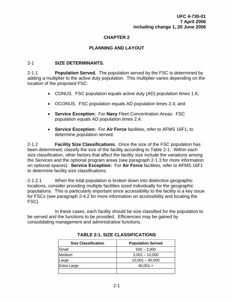
TABLE 2-1. SIZE CLASSIFICATIONS
Size Classification Population Served Small 500 – 3,000 Medium 3,001 – 10,000 Large 10,001 – 40,000 Extra Large 40,001 +
2-1

UFC 4-730-01 7 April 2006
including change 1, 20 June 2006 2-1.2.2 For populations less than 500, accommodate the FSC functions in other, non-dedicated facilities. Consider multiple facilities for very large or geographically dispersed populations.
2-1.3 Optional Spaces. Once the size classification has been determined, select the desired optional spaces (see paragraph 1-3 for more information on optional spaces). The Base/Installation/Station representatives, in conjunction with the project manager, must decide which optional spaces to provide.
2-2 SPACE PROGRAMS. Once the size classification has been determined and the optional spaces selected, the facility space program is determined by using Tables C-1 through C-4 in Appendix C. These tables show the basic functional spaces and the appropriate area for those spaces organized by size classification. Service Exception: For Air Force facilities, refer to Air Force Handbook (AFH) 32-1084, for FSC space requirements. Some spaces not included in AFH 32-1084 may be required for FSCs. The minimum space requirements for those spaces are included in Table C-5. \1\ Interactive spreadsheet available from WBDG DoD page, http://dod.wbdg.org./1/
The space programs illustrated in Tables C-1 through C-4 serve as guidelines for the FSC planning team. The final space requirements for elements such as toilets, mechanical spaces, parking, etc. are governed by codes and must be determined by qualified designers. Additionally, the final space requirements for the FSC programmed spaces will also need to be carefully determined by Installation representatives and the appropriate Service program office guided by the criteria in this UFC.
2-2.1 Space Program Tables.
2-2.1.1 Tables C-1.1 through C-1.4 illustrate the complete Army space program and include both the required and optional spaces. Develop the space program for an Army FSC using these tables independent of the other Services.
2-2.1.2 Table C-2 illustrates the size program for the elements of an FSC that are “unified” among the Navy and Marine Corps. These are the spaces that both of these Services include in their FSC facilities.
2-2.1.3 Table C-3 illustrates the Navy-specific spaces and includes both the required and optional spaces. The total Navy FSC space program is generated by combining the total of the unified spaces in Table C-2, the total of the required Navy-specific spaces, and the total of the selected optional Navy-specific spaces.
2-2.1.4 Table C-4 illustrates the Marine Corps-specific spaces and includes both the required and optional spaces. The total Marine Corps FSC space program is generated by combining the total of the unified spaces in Table C-2, the total of the required Marine Corps-specific spaces, and the total of the selected optional Marine Corps-specific spaces.
2-2

UFC 4-730-01 7 April 2006
including change 1, 20 June 2006 2-2.1.5 As noted above, the space program for Air Force FSCs is provided in AFH 32-1084. Table C-5 illustrates the space criteria for some potential additional spaces that are not included in AFH 32-1084.
2-2.2 Space Allocation Standard. The tables calculate the estimated area for each functional space based on a Space Allocation Standard. This standard provides the space required for the smallest possible unit of the functional space in question. For example, the Space Allocation Standard for a Classroom provides the space needed to seat 15 people—since it is understood that the Services would not plan a Classroom for fewer than 15 people. The space standard is then multiplied to accommodate additional classroom space as needed. Note that the space programs do not dictate how this space is to be used. If the program suggests that space is needed for 60 people (four groups of 15), it could be configured as either one large partitionable room or multiple smaller rooms as best serves. See paragraph 4-6 for more information on Classrooms.
2-3 ESTIMATED STAFFING. The space program tables also include estimated facility staffing by size classification. This is provided as an additional tool for planning personnel to judge facility requirements. Note that in smaller facilities, staff positions may be shared so that the total number of “positions” accommodated by the facility may not equal the total number of staff. Further, staff positions may not be shared consistently from facility to facility. Therefore, final staffing must be carefully determined by the appropriate installation and program office personnel. The numbers provided in this UFC serve as a rough guideline only.
Service Exception: For Air Force staffing, refer to AFMS 16F1.
2-4 LOCATION DETERMINANTS. Several factors determine the most appropriate and cost-effective location for an FSC.
2-4.1 Site Size. Ensure adequate site space for the following elements when selecting the FSC site:
• Parking space for customers and staff,
• Space and access for the Lending Locker loading dock/exterior access,
• Service drive, and
• Antiterrorism (AT) setback criteria. See paragraph 3-8 for more information on antiterrorism requirements.
2-4.2 Customer Access. Design the FSC to be easily accessible by all potential facility customers. The importance of access by spouses, dependants, or non-active duty personnel that may be coming from off Installation must not be overlooked.
Consider locations such as near the Installation gate or other high activity or population centers such as the commissary, retail exchange, medical facilities, or “one-stop shopping” areas. As an alternative, consider locating the FSC off-installation
2-3

UFC 4-730-01 7 April 2006
including change 1, 20 June 2006 at sites like the Installation visitor’s center or local high-traffic commercial/retail centers. If the FSC is located off-base, consider the antiterrorism impacts in the design of the facility (see paragraph 3-8 for more information on antiterrorism requirements).
Also consider that while the primary FSC facility may need to be located on base, additional remote, off-base facilities can be used to serve the non-active-duty customers.
2-5 COST. Design FSCs with the objective of achieving a low life cycle cost. To do so, the project’s design program must adequately define the scope and performance requirements and match those needs against a budget. Conversely, the budget must adequately support an appropriate and high-quality program and the performance and technical requirements (such as sustainable design and antiterrorism criteria) identified in this UFC.
2-6 LAYOUT AND ADJACENCIES.
2-6.1 General. The spatial relationships in the FSC are best described in terms of the transition from public spaces to private spaces.
2-6.1.1 Public Spaces. These are spaces that the customers need ready access to and may be able to enter unattended. Locate public spaces near the main entrance. The public spaces comprise the following:
• Lobby/Waiting Area,
• Reception/Information/Referral Area,
• Computer Lab,
• Toilets, and
• Classrooms.
2-6.1.2 Semipublic Spaces. These are spaces that customers need access to, but will usually enter accompanied by a staff member. The semipublic spaces comprise the following:
• Relocation assistance (including Lending Locker),
• Transition assistance, and
• Employment support.
2-6.1.3 Private Spaces. These are spaces that customers will not normally enter, or that customers will enter only with a staff member. They require a high degree of privacy (such as a counseling office). The private spaces comprise the following:
2-4

UFC 4-730-01 7 April 2006
including change 1, 20 June 2006 • Program offices requiring privacy, such as those under financial
management or EFMP,
• Counseling offices,
• Decompression/waiting room,
• File storage, and
• Staff offices and work areas.
2-6.2 Functional Relationship Bubble Diagram. This bubble diagram indicates acceptable relative adjacencies of the key functional spaces.
FIGURE 2-1. FUNCTIONAL RELATIONSHIP BUBBLE DIAGRAM
1 Only Army and Navy provide counseling in their FSCs. 2 A separate, exterior entrance is strongly desired for the Lending Locker. But if a separate, exterior entrance is not possible, provide a direct connection between the Lending Locker and the Lobby.
2-6.3 Illustrative Diagrams. Figures 2-2 and 2-3 are illustrative diagrams of the FSC. These diagrams are not intended to represent mandatory or even suggested
2-5

UFC 4-730-01 7 April 2006
including change 1, 20 June 2006 layouts but are provided to expand on Figure 2-1 and illustrate the relative sizes of the functional spaces along with the acceptable adjacencies. By including the relative sizes of the spaces, these diagrams convey a possible means to accommodate the needed adjacencies. Of the two diagrams provided, one accommodates a traditional operational approach and one accommodates an alternate operational approach. These two operational approaches vary in terms of space usage and operational flexibility. When planning an FSC, consider these issues along with mission requirements.
2-6.3.1 Traditional Layout. Figure 2-2 illustrates a facility that uses a traditional operational approach. In this approach, staff members meet with customers in dedicated offices. Service Note: The Army supports and maintains the traditional operational approach.
FIGURE 2-2. TRADITIONAL LAYOUT ILLUSTRATIVE DIAGRAM
1 Only Army and Navy provide counseling in their FSCs.
RA = relocation assistance, EA = employment assistance, TA = transition assistance
2-6.3.2 Alternate Operational Approach Layout. Figure 2-3 illustrates a facility that uses an alternate operational approach. In this approach, program staff members do not normally meet with customers in their own offices or workspaces, but they use Interview Rooms that are shared by all programs. The net effect of this approach is that the Administrative/Office area grows in size to accommodate cubicles for program staff, but that growth is more than offset by the reduction in the number of dedicated program
2-6

UFC 4-730-01 7 April 2006
including change 1, 20 June 2006 offices. Service Note: The alternate operational approach is optional for the Navy, Air Force, and Marine Corps. For Air Force, particularly consider using the alternate operational approach for Air Force Reserve Unit FSCs.
In some cases, programs that do not use the alternate operational approach will also use Interview Rooms to meet other functions and have a similar building configuration.
FIGURE 2-3. ALTERNATE LAYOUT ILLUSTRATIVE DIAGRAM
2-6.4 Space Assessment. See Chapter 4 for additional information on the space types and their relationships to each other.
2-7 ALTERATIONS TO EXISTING FACILITIES.
2-7.1 General. FSCs are frequently placed in existing facilities, and therefore, need special attention when selecting the appropriate existing facility for adaptation to FSC functions. Only consider permanent facilities for conversion to an FSC.
2-7

UFC 4-730-01 7 April 2006
including change 1, 20 June 2006 Exceptions may be made for other buildings that are in excellent condition, subject to the location determinants in paragraph 2-4.
Consider adaptability to the intent of the building program. For instance, can the building/site accommodate the vehicular access desired for the Lending Locker? Will the building be able to service a need during an emergency crisis response time? Does the existing building allow for easy access by non-active duty personnel or family members?
Whether planning a conversion, alteration, addition, or new construction, barrier-free design requirements and antiterrorism requirements must be taken into account (see paragraphs 3-7 and 3-8).
2-7.2 Regulatory Authorities. Refer to the following for the appropriate Service-specific authorities:
• Army. U.S. Army Technical Instruction (TI) 800-1, and Army Regulation (AR) 608-1.
• Navy and Marine Corps. Authorities are contained in OPNAVINST 11010.20F and NAVFACINST 11010.45. When planning alterations to an existing facility to convert it to an FSC, for Navy, consult with Fleet and Family Support Branch (PERS 660), and for Marine Corps, consult with HQ USMC, Manpower and Reserve Affairs, Code MR.
• Air Force. HQ AFCEE for architectural, landscape, interior design, and publication coordination; HQ Air Force Civil Engineering Support Agency (AFCESA) for technical issues relating to fire, life safety, and certification; Air Force Family Matters (AFFAM/DPPFF) for functional requirements and policies.
2-8
UFC 4-730-01 7 April 2006
including change 1, 20 June 2006
CHAPTER 3
GENERAL DESIGN CRITERIA
3-1 GENERAL. Use UFC 1-200-01 for guidance on the use of model building codes for design and construction of DoD facilities. See paragraph 3-5 for the appropriate governing codes for building services.
3-2 STRUCTURE. Refer to UFC 3-310-01.
3-2.1 Foundation. The foundation is site specific and must be designed upon known geotechnical considerations by a professional engineer knowledgeable of the local conditions.
3-2.2 Superstructure. Use pre-engineered components for superstructure framing, where feasible.
3-2.3 Materials. Consider climate conditions, high humidity, industrial atmosphere, salt water exposure, or other adverse conditions when selecting the following:
• The type of cement and admixtures used in concrete,
• The concrete cover on reinforcing steel in the concrete membrane,
• The coatings on structural members,
• Expansion joints,
• The level of corrosion protection, and
• The structural systems.
3-3 EXTERIOR DESIGN. In general, the building’s image, theme, and fixtures must be consistent with the programs offered. Design the building to reflect the local geographical and cultural environment and to comply with the appropriate Service architectural standards (i.e. Base Exterior Architecture Plan or other Installation standards). The building and site should provide a visually attractive and welcoming appearance with ample parking and signs providing directions to the site.
3-3.1 Entrance. The main entrance should incorporate a clearly identifiable point of reference or landmark that serves as a welcome and a transition. A transition such as a covered entry is very desirable at the main entry. In cold climates, provide a canopy (or a recess) at required egress doors to ensure that doors can open completely without obstruction from snow and ice.
3-1

UFC 4-730-01 7 April 2006
including change 1, 20 June 2006 3-3.2 Exterior Finishes. The color, texture, and design should be consistent with the building material available to the area and therefore be appropriate for the building type and comply with any applicable Installation design standards. The design intent and character of the FSC should provide the appearance and environmental setting of a professional business office. The FSC should always present an expression of informality, comfort, and clear organization. The design should invite relaxed conversation, suggest discretion, and above all, promote confidence in the professional services offered. Coordinate the exterior finishes with the Service-specific design standards noted below in paragraph 3-4.2 for interior finishes.
3-3.3 Exterior Signage. Equip the main entrance with an attractive, clearly located sign that provides the program hours of operation. Ensure that signage complies with Installation requirements. Sign placement and type are site-specific, but signs must be strategically located, adequately lit, and of sufficient size to permit proper viewing by individuals approaching the facility.
Service Exception: For Air Force projects, comply with UFC 3-120-01.
3-4 INTERIOR DESIGN. Construction and finishes (walls, floor, and ceiling) should support the image and theme of the facility and be consistent with the programs offered. The interior design should offer interest, excitement, and professionalism. In general, use warm, welcoming colors and textures—avoid “institutional” colors and appearance.
Provide professional interior design services in the same manner as standard A/E services. Coordination and planning among the architectural and interior designers are critical.
3-4.1 Interior Construction. Provide counters, casework, and cabinets of high-quality and durable construction. Specify Architectural Woodwork Institute (AWI) Premium or Custom for finishes per AWI Quality Standards Illustrated. Provide casework, cabinet doors, and drawer faces as veneer panel core. Doors, drawers, and casework faces should be plastic laminate at a minimum. Where no water source is present, countertops should be plastic laminate as a minimum with hardwood or solid surface edging. Where a water source is present, provide countertops of solid surface/solid composite plastics only. Specify 20-mm (.75-in.) minimum thickness for plywood, plywood backing, and solid wood panels.
All interior glass must be tempered safety glass and mirrors must be made of break-resistant materials. Also consider the use of glass block as an interior construction material to add visual interest and permit more light.
Provide window treatments to control light levels within all offices and classrooms (occupied spaces).
3-4.2 Finishes. Finishes should take into account the intended uses and be appropriately durable. They must meet the requirements listed in NFPA 101. Service
3-2

UFC 4-730-01 7 April 2006
including change 1, 20 June 2006 Exception: Also coordinate the interior (and exterior) design with the following Service-specific standards or agencies:
• Army. DG 1110-3-122, and Installation Design Guide Standards;
• Navy and Marine Corps. UFC 3-100-10N,; and
• Air Force. USAF Interior Design Guide, applicable Major Command and Installation design standards.
In moist climates, do not cover the inside of exterior walls with impervious materials such as mirrors or vinyl wall coverings. This will help prevent mold development in the wall.
Table 3.1 provides a finish schedule for FSCs.
TABLE 3-1. FINISH SCHEDULE
Recommended Finishes
General Space Floor Base Walls Ceiling Notes Lobby and Waiting CPT/QT/CT CT/QT/VB Note 1 ACP/GWB Note 2 Classroom CPT/VCT VB GWB ACP Office/Clinical CPT VB GWB ACP Lending Locker SCF None/VB CMU/GWB None/ACP Kitchen VCT VB CT/GWB ACP/GWB Note 3 Toilets CT CT CT/GWB GWB
Key: ACP – Acoustic Ceiling Panel GSU – Glazed Structural Wall SCF – Sealed Concrete Floor CMU – Concrete Masonry Unit GWB – Gypsum Wall Board SV – Sheet Vinyl, slip resistant CPT – Carpet GWC – Glazed Wall Coating VB – Vinyl or Rubber Wall Base CT – Ceramic Tile QT – Quarry or Stone Tile VCT – Vinyl Composition Tile
Notes: Note 1 – Walls in public areas may be made of a variety of durable materials such as brick or split block Note 2 – Child Play area should be CPT, VCT, and/or SV Note 3 – Moisture-resistant Ceiling Panel system
3-5 SERVICES. Also see paragraph 3-9 for information on sustainable design and energy consumption.
3-5.1 Plumbing. Design domestic hot and cold water, sanitary and storm drainage, propane, fuel oil, or natural gas systems to meet the requirements of local Installation standards and UFC 3-420-01.
3-5.2 Heating, Ventilating, and Air Conditioning (HVAC). Design the HVAC system to meet the requirements of the most current edition of the International Mechanical Code (IMC); UFC 3-410-01FA, Design: Heating, Ventilating, and Air Conditioning; and UFC 3-410-02A, Design: Heating, Ventilating, and Air Conditioning
3-3

UFC 4-730-01 7 April 2006
including change 1, 20 June 2006 (HVAC) Control Systems. Comply with antiterrorism requirements in the design of the HVAC system (See paragraph 3-9).
Consider climate conditions, high humidity, industrial atmosphere, saltwater exposure, or other adverse conditions to ensure durability when selecting exterior HVAC components.
3-5.3 Fire Protection. Design fire protection and life safety to comply with UFC 3-600-01.
3-5.4 Electrical. Provide electric service and distribution equipment, wiring receptacles and grounding, interior and exterior lighting and control, emergency lighting, telephone and communication systems, fire alarm, and intrusion systems in accordance with NFPA 70; UFC 3-520-01; and the latest Installation design requirements. See the latest edition of Electric Current Abroad, to determine voltages and cycles in overseas locations. Service grounding system and all wiring methods must meet the current NFPA 70 requirements. All service equipment must be Underwriters Laboratories (UL) listed. Alternately, published proof from an approved independent testing laboratory may be provided.
3-5.4.1 Lighting. Provide lighting and control systems throughout the facility in accordance with UFC 3-530-01.
3-5.4.2 Communications and Data. Telephone and data outlets may be independent of each other or combined into a single junction box. If these connections can be combined into a single junction box, the cover plate to that junction box must allow for multiple connections. In some unique situations, the cable television (CATV)/internal video connection can be combined into a single junction box with the appropriate cover plate.
Confirm the preference for individual or combined telephone/data/video outlets with the following Service-specific contacts:
• The Installation Manager for Army and Air Force projects and
• HQ Program Managers for Navy and Marine Corps projects.
Service Exception: For Air Force projects, also refer to Engineering Technical Letter (ETL) 02-12, Communications and Information System Criteria for Air Force Facilities.
3-5.4.3 Security Alarm System. Consider providing an alarm system for intrusion detection to protect equipment and assets. Provisions for an alarm system must be justified during the planning/programming process. Service Exception: The Navy does not fund security alarm systems. If desired, the individual Navy Installation must provide the funding for an alarm system.
3-4

UFC 4-730-01 7 April 2006
including change 1, 20 June 2006 3-5.4.4 Duress Alarm System. If clinical counseling services are provided, an internal, silent duress alarm system may be required. This system usually includes activation buttons at the I&R area and in the counseling offices. When pressed, the button activates an alarm at the I&R and management areas. This allows the counselor or staff member to signal for help if necessary. See paragraphs 4-5 and 4-9.3.2 for more information.
3-6 SITE WORK.
3-6.1 Landscaping. Landscaping should be appropriate to the professional nature of the facility and reflect the local geographical environment. The plant selection should be easy to maintain and enhance the visual quality of the facility in all seasons. Indigenous species are preferred. Comply with UFC 3-210-05FA and the local Installation landscape standards. Service Exception: For Air Force, also refer to the USAF Landscape Guide and any Major Command standards.
Provide professional landscape architecture design services in the same manner as standard A/E services. Coordination and planning among the architectural and landscape designers are critical.
3-6.2 Parking and Access Drives. Provide adequate parking for both staff and patrons with the appropriate access drives. Consider location of bicycle racks near the facility entrance in a secure location. Comply with UFC 3-210-02. See the following Service-specific documents to determine the required number of parking spaces:
• Army and Air Force. Work with the program manager and applicable codes and regulations to determine the appropriate number of parking spaces; and
• Navy and Marine Corps. NAVFAC P-80.
3-6.3 General Site Lighting. Ensure that parking areas and the facility have adequate lighting for safety, evacuation, and security measures. Comply with UFC 3-530-01.
3-7 BARRIER-FREE DESIGN REQUIREMENTS. Design FSCs to be barrier-free and accessible in compliance with the Architectural Barriers Act (Public Law 90-480) of 1968, http://www.access-board.gov/ufas/ufas-html/ufas.htm - ABA. Provide barrier-free design requirements in accordance with the Uniform Federal Accessibility Standards (UFAS), published as Federal Standard (FED-STD)-795, http://www.access-board.gov/ufas/ufas-html/ufas.htm, and 28 CFR Part 36, the Americans With Disabilities Act Accessibility Guidelines for Buildings and Facilities (ADAAG), http://www.access-board.gov/adaag/html/adaag.htm.
The ADA and ABA Accessibility Guidelines for Buildings and Facilities, http://www.access-board.gov/ada-aba.htm, was published in July 2004. These updated guidelines will supersede the Uniform Federal Accessibility Standards (UFAS), published as Federal Standard 795 and Americans With Disabilities Act Accessibility
3-5

UFC 4-730-01 7 April 2006
including change 1, 20 June 2006 Guidelines (ADAAG) when adopted by the Department of Defense. Until then these updated guidelines are not enforceable and UFAS and ADAAG still apply. When the new guidelines are adopted, they will be referenced in this section and the criteria outlined in this section modified as necessary.
3-8 ANTITERRORISM REQUIREMENTS. Design the facility to comply with UFC 4-010-01, and UFC 4-021-01.
3-9 SUSTAINABLE DESIGN. Use an integrated approach to the planning and design of FSCs that minimizes energy consumption and optimizes life cycle cost renewable energy possibilities. Use a practical combination of site selection and siting, energy conserving building envelope technologies, energy efficient lighting, occupant sensing controls, variable frequency drives for motors and exhaust fans, and high efficiency HVAC systems to achieve this goal. Incorporate renewable energy principles such as day-lighting, passive and active solar heating, natural ventilation, and photo-voltaics where they are life cycle cost effective.
Follow the guidance in UFC 3-400-01.
A new UFC addressing sustainable design is in draft form. When it is released, it will be referenced in this section and the criteria outlined in this section modified as necessary.
3-9.1 Service Specific. See the following Service-specific requirements:
3-9.1.1 Army. Design FSC projects with consideration for sustainable ratings in eight facility categories: Sustainable Sites, Water Efficiency, Energy and Atmosphere, Materials and Resources, Indoor Environmental Quality, Facility Delivery Process, Current Mission, and Future Missions. The minimum rating for the Army’s Sustainability Project Rating Tool (SPiRiT) must be in accordance with the current rating. Most projects can reach the sustainability rating without increasing costs, while improving Installation sustainability and balancing available resources with customer requirements. Understanding and applying the principles of Sustainable Design and Development and using the SPiRiT rating process improve day-to-day decisions and project quality.
3-9.1.2 Navy and Marine Corps. Use the United States Green Building Council (USGBC) LEED™ Green Building Rating System to measure the sustainability of the completed project. It can also be used during planning and design as a source of green building strategies. LEED™ addresses sustainable sites, water efficiency, energy and atmosphere, materials and resources, and indoor environmental quality. The minimum LEED™ rating of “Certified” should be met within budgetary constraints. Actual certification is encouraged, but not required.
3-9.1.3 Air Force. It is Air Force policy to apply sustainable development concepts in the planning, design, construction, environmental management, operation, maintenance, and disposal of facilities and infrastructure projects, consistent with
3-6

UFC 4-730-01 7 April 2006
including change 1, 20 June 2006 budget and mission requirements. Refer to HQ USAF/ILE Memo, Sustainable Development Policy and the Air Force Sustainable Facilities Guide.
3-9.2 Other Sustainable Design Criteria. The following general references provide more information:
3-9.2.1 When specifying products that are included in EPA’s list of affirmative procurement guideline items, include the requirement for these products to meet or exceed the recycled material content standards established by EPA. The list of products and their corresponding recycled content requirements are found at www.epa.gov/cpg/products. Listed products likely to be used in FSCs include building insulation, carpet and cushion, cement and concrete, latex paint, floor tiles, patio blocks, restroom dividers, and structural fiberboard.
3-9.2.2 The “Whole Building Design Guide” www.wbdg.org further explains the environmental issues related to building materials and provides technical guidance on green building material selection.
3-9.3 DoD Energy Budget. Design of new facilities must ensure that building energy consumption does not exceed the DoD energy budget figures.
3-7

UFC 4-730-01 7 April 2006
including change 1, 20 June 2006
CHAPTER 4
SPECIFIC DESIGN CRITERIA
4-1 INTRODUCTION. This chapter identifies the specific needs for each functional area as outlined in the space program.
4-2 LOBBY. The Lobby is the entry point for staff and customers. It should be a warm and relaxing space that is simple and straightforward in its design. It should convey a sense of privacy and should not be designed to intimidate or overly impress sensitive customers. The Lobby should allow for easy circulation to and between the many public functions within the facility.
4-2.1 Lobby ceiling height must be a minimum of 2.74 m (9 ft.).
4-2.2 Provide an airlock at the main entrance. Provide additional data and electrical outlets (beyond code minimum) for flexibility should the Lobby be used for alternate activities.
4-2.3 Beyond standard ambient lighting, consider providing decorative lighting. This will make the Lobby, and in turn the whole facility, feel more welcoming and inviting. Also consider free standing or built-in display cases and elements such as a pay phone, integral/recessed walk-off grate, and an umbrella rack.
4-2.4 Note that a separate exterior entrance to the Lending Locker is required for new construction and strongly preferred for refit projects (see Paragraph 4-10). However, if a separate exterior entrance to the Lending Locker is not provided, consider providing a power-operating door from the Lobby to the Lending Locker to ease moving equipment in and out.
4-3 LOBBY WAITING AREA. Directly accessible from the Lobby, the Lobby Waiting Area acts as a public waiting room for customers of the center. The space should be warm, comfortable, and secure. The seating arrangements should be intimate and allow for a sense of privacy. There should be distractions such as a TV or magazines to allow each customer an opportunity to focus his or her attention away from other customers.
4-3.1 Provide ADAAG-accessible toilet facilities and water fountain that are conveniently located near the Lobby/Lobby Waiting Area. Accommodate a TV set; consider wall or ceiling mounting or a recessed set. Accommodate a wall-mounted clock. As with the Lobby, provide additional data and electrical outlets for flexibility if Lobby is used for alternate activities. Provide furniture such as upholstered armchairs, side tables, bookshelves, and magazine racks.
4-3.2 Consider providing a space within the Lobby Waiting Area where children might sit and play quietly under parental supervision (also see Paragraph 4-4). This
4-1

UFC 4-730-01 7 April 2006
including change 1, 20 June 2006 sub-space may be partitioned off from the rest of the Lobby Waiting Area. As with the Lobby, consider providing decorative lighting such as table and/or floor lamps.
4-4 SHORT-TERM ALTERNATIVE CHILD CARE (STACC). This Army-only option provides childcare services for parents attending classes. Refer to Army Regulation (AR) 608-10, for more detailed information on this space.
4-5 INFORMATION AND REFERRAL (I&R). Locate this space within the Lobby; it acts as the welcome desk for the center. It should also function as the entry security point, but it should not be intimidating or overwhelming. Staff should sit comfortably at the desk and perform office functions as well as interact with customers, assisting them with directions and information. The I&R desk should have direct visibility to the many public functions accessible from the Lobby. There may be an office component to the I&R in larger facilities. Service Exception: The Air Force refers to this as the Reception area.
4-5.1 Provide the following design elements:
• An I&R welcome desk consisting of a dual height counter with built-in storage and a 610-mm-deep (24-in.) work surface;
• Additional lockable wall and base cabinets for storage of equipment and supplies. Use durable materials for the counter top and front surface;
• A gate between the desk and surrounding area;
• Special decorative lighting above the desk and task lighting above the work surface;
• Power and data outlets for telephones, fax machines, computers, and printers; and
• Adjustable office chairs for behind the counter.
4-5.2 Consider providing a coiling door or a metal pull-down grille at the desk as a security screen.
4-5.3 For facilities that provide clinical counseling, a duress alarm system may be provided (see paragraph 3-5.4.3). If this is the case, provide both an alarm activation point and an alarm indicator in a discrete location under the counter.
4-6 CLASSROOM(S). Much of the center’s mission focuses on information and education as a means of prevention. The classroom(s) is/are central to the mission and their importance to the facility should not be underestimated. Locate classrooms near the entrance and design to be easily accessible from the Lobby. They should be configured to allow flexibility in size and configuration and be designed with the infrastructure to allow for a wide variety of media presentations. When required, design one of the classrooms to easily transform into the Crisis Action/Response Room.
4-2

UFC 4-730-01 7 April 2006
including change 1, 20 June 2006 4-6.1 If there is only one classroom in the facility, provide a sound-rated, movable partition. And even if the facility contains multiple classrooms, consider providing movable partitions to increase programmatic and scheduling flexibility.
4-6.2 Ensure adequate power and data connections. If the classroom space will be used for alternate activities, such as a Crisis Action/Response Room, provide additional data and electrical outlets. Accommodate audio-visual equipment in the infrastructure. Locate audio-visual outlets throughout the classroom to accommodate all the room configurations possible with the partitions.
4-6.3 Provide the following additional design elements:
• A wall-mounted clock in each classroom or in each classroom section in rooms with partitions,
• Movable or fixed dry-erase boards,
• Tackable surfaces throughout the classroom, and
• Casework in every classroom for storage of supplies and equipment. Casework should consist of base and wall cabinets with a 610-mm-deep (24-in.) work surface.
4-6.4 Consider providing the following design elements:
• A small sink within the casework. If a sink is provided comply with all codes and use a solid-surface counter at the sink;
• An exterior door to at least one classroom. This will allow after-hours programs to be conducted without keeping the rest of the facility open; and
• A movable stage and auditorium-style seating for very large presentations, such as deployment briefings. This should only be considered if there is a classroom large enough to hold enough people to make it worthwhile.
4-6.5 Furniture will consist of chairs, tables, and possibly small area rugs. The tables and chairs should be stackable and easily stored.
4-7 TEACHING KITCHEN. This optional space accommodates instructional programs where military personnel and/or their families can learn cooking and serving techniques for family meals. Consider adjacency to the Classrooms and the Staff Break-room (see paragraph 4-17) as there may be opportunities to accommodate dual functions in this space.
The layout and appliances should be residential type. locate the microwave oven, baking oven, dishwasher, four-burner cook top with hood, and
4-3

UFC 4-730-01 7 April 2006
including change 1, 20 June 2006 refrigerator with ice-maker within close proximity to ensure efficient and comfortable use.
Plan viewing angles for all workspaces to ensure that students can see the activities. Consider creating an island work area for ease of demonstration. This work area should include cook top, sink, and preparation area. Consider providing an adjustable mirror over the preparation area to allow students to view the activities.
4-7.1 Provide the following design elements. All fixtures must comply with all relevant codes:
• Appropriate plumbing fixtures to support cooking and cleaning in the teaching kitchen. Provide a hand sink in addition to the pot sink for sanitation;
• Garbage disposals at the sinks;
• An exhaust system over the cooking area;
• Durable cabinetry and work surfaces. A 610-mm-deep (24-in) solid surface counter top is recommended; and
• Task lighting at work areas.
4-7.2 If the Kitchen is located separately from the Staff Break-room, consider accommodating an eat-in area with tables and chairs.
4-8 COMPUTER RESOURCE AND INFORMATION LAB. Like the classrooms, the Computer Resource and Information Lab is central to the FSC’s mission and consolidates all the center’s information for use in a more individualized and independent manner. Directly accessible from the Lobby, this Lab should be well organized and allow for information displays, computer kiosks, research carrels, and general workspace. The room should be friendly, comfortable, and inviting. Staff workspaces adjacent to the Lab should also be inviting and open to encourage questions.
4-8.1 Provide the following design elements:
• An adequate number of data and power outlets to accommodate all computer work stations and additional equipment, such as printers, scanners, etc.;
• Display cases or kiosks designed as either free standing furniture or built-in;
• Lockable base and wall cabinets for storage of supplies and equipment. Provide a 610-mm-deep (24-in.) counter work area with power and data outlets at counter height; and
4-4
UFC 4-730-01 7 April 2006
including change 1, 20 June 2006 • Tackable surfaces and movable or fixed dry-erase boards.
4-8.2 Accommodate an adjustable office chair at each workstation. Consider providing storage space for additional adjustable office chairs to support multiple users at a workstation.
4-8.3 Consider providing some upholstered furniture like armchairs and sofas, arranged to support private conversations.
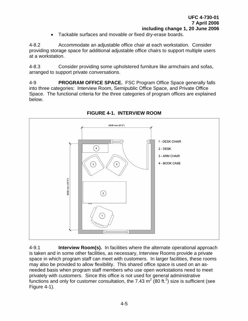
4-9 PROGRAM OFFICE SPACE. FSC Program Office Space generally falls into three categories: Interview Room, Semipublic Office Space, and Private Office Space. The functional criteria for the three categories of program offices are explained below.
FIGURE 4-1. INTERVIEW ROOM
4-9.1 Interview Room(s). In facilities where the alternate operational approach is taken and in some other facilities, as necessary, Interview Rooms provide a private space in which program staff can meet with customers. In larger facilities, these rooms may also be provided to allow flexibility. This shared office space is used on an as-needed basis when program staff members who use open workstations need to meet privately with customers. Since this office is not used for general administrative functions and only for customer consultation, the 7.43 m2 (80 ft.2) size is sufficient (see Figure 4-1).
4-5

UFC 4-730-01 7 April 2006
including change 1, 20 June 2006 4-9.1.1 Design to convey a strong sense of privacy through the use of full-height partitions extending to the underside of structure with sound insulation. Provide a Sound Transmission Coefficient (STC) rating of 50 to 55.
4-9.1.2 Provide a quad power/data/telephone outlet on at least three walls of the office. Furniture will consist of a desk or a table, an adjustable office chair, and desk chairs. Provide vision panel doors or sidelights.
4-9.1.3 Consider providing residential type accents and task lighting such as table and floor lamps.
4-9.2 Semipublic Office Space. These areas of the FSC house the office space for relocation assistance, transition assistance, and employment support programs/services. They are distinguished as semipublic for two reasons: One, they are directly adjacent to public spaces such as the Lobby or the Computer Resource and Information Lab, and two, the programs offered out of these offices require a more casual and impromptu interaction with customers than in the Private Program Office Space. Design these offices to accommodate general staff office functions as well as customer interaction and personalized discussions. These office spaces may act in support of the Computer Resource and Information Lab.
4-9.2.1 The office will typically be configured as in Figure 4-2. Furniture will include modular office furniture consisting of a desk or workstation, credenza with overhead storage, file cabinet, desk chair, and an additional two chairs. The furniture configuration allows the staff member to hold working consultations with customers and for both parties to use the desk as work-space.
4-9.2.2 Provide a quad power/data/telephone outlet on at least three walls of the office, or at least one per staff member. Provide additional outlets as needed to operate additional equipment. Provide vision panel doors or sidelights.
4-9.2.3 Consider providing residential task and accent lighting such as desk and floor lamps.
4-6

UFC 4-730-01 7 April 2006
including change 1, 20 June 2006
FIGURE 4-2. SEMIPUBLIC OFFICE
4-9.3 Private Office Space. Private offices fall into two categories: One, they are less likely to accommodate direct customer interaction in the office (workstations), or two, the direct customer interaction requires a high degree of privacy (individual offices).
4-9.3.1 Workstations. Staff members who use this type of office space tend to interact directly with their customers in the Classroom or Computer Lab settings or they are encouraged to counsel outside of the office and often travel to remote locations. Their office space will consist of open and collaborative workstations. When they need to meet with customers on an individual, private basis they will use the Interview Rooms (see paragraph 4-9.1). Since these staff members will often engage customers in large groups and seminars, their office space should allow them adequate space and resources to put these presentations together.
4-9.3.1.1 Provide the following design elements:
• Open-space modular workstation furniture;
4-7

UFC 4-730-01 7 April 2006
including change 1, 20 June 2006 • A layout area with supply storage in conjunction with the modular
workstations. Accommodate adjustable height office chairs in the layout area;
• The appropriate power, phone, and data requirements;
• At least one quad power/data/telephone outlet per staff member; and
• Task lighting in each workstation.
4-9.3.1.2 Consider providing other equipment such as printers, fax machines, scanners, etc. and the supporting power and data outlets.
4-9.3.2 Individual Offices. Staff members who use this type of office space provide more intimate counseling functions, such as EFMP or clinical counseling. This office space will consist of extremely private, individual offices. Design to comfortably seat at least three adults in a quiet, non-threatening setting. Between sessions, the office should allow staff to work on files, read, and research cases.
4-9.3.2.1 The office will typically be configured as in Figure 4-3. Furniture will include modular office furniture consisting of a desk or workstation, credenza with overhead storage, file cabinet, and desk chair. Provide additional furniture such as an upholstered love seat, an upholstered armchair, and a side table. The furniture configuration allows the staff member to meet with customers in a more intimate, less threatening setting. The desk should not divide the staff member from the customer.
FIGURE 4-3. PRIVATE PROGRAM OFFICE (INDIVIDUAL OFFICE)
4-8

UFC 4-730-01 7 April 2006
including change 1, 20 June 2006
4-9.3.3 Design to convey a strong sense of privacy through the use of full-height partitions extending to underside of structure with sound insulation. Provide a Sound Transmission Coefficient (STC) rating of 50 to 55. Provide a quad power/data/telephone outlet on at least three walls of the office. Provide additional outlets as needed to operate additional equipment.
4-9.3.3.1 Consider providing task lighting in each office. For clinical counseling offices or other offices where sensitive discussions with customers may take place, consider providing a duress alarm activation point in a discrete location within easy access for the staff member. This activation point will activate a silent alarm at the reception and management areas so that the counselor or staff member can signal for help.
4-10 LENDING LOCKER. This subset of the relocation assistance program is a storage room for items such as pots, pans, and irons that may be loaned to recently relocated military personnel and their families. Design with adequate and varied shelving to accommodate the many different types of items in the locker’s inventory. As many of the items may be bulky or heavy (such as a futon), provide direct access to an exterior loading area for easy customer loading and unloading. If a separate exterior entrance is not possible for a refit project, locate the Lending Locker adjacent to the Lobby and with direct access to the front entrance. See Figure 4-4 for an illustration of the basic space unit of the Lending Locker. The space illustrated corresponds to the
4-9

UFC 4-730-01 7 April 2006
including change 1, 20 June 2006 space allocation standard “room unit” in the space programs in Appendix C. This self-contained unit can be expanded for larger facilities if more space is required.
4-10.1 Provide the following design elements:
• Lockable interior and exterior doors;
• A commercial-grade dishwasher and a deep, utility-style sink with adjacent drying area for cleaning returned items (Service Exception: dishwasher and sink are optional for the Army.); and
• Heavy-duty metal storage shelving units.
4-10.2 Consider providing the following design elements:
• A keyless entry system on the exterior doors,
• A high-density storage system,
• A table or layout area that would be used for inventory during check-in and check-out,
• Industrial-style fluorescent lighting, and
• Additional lockable storage or a security system for high-value items (e.g. televisions).
FIGURE 4-4. LENDING LOCKER SPACE UNIT
4-10

UFC 4-730-01 7 April 2006
including change 1, 20 June 2006
1 Service Exception: Dishwasher and sink are optional for the Army.
4-10.3 Service Exception: The Air Force includes the following optional spaces: Airman’s Attic and Food Pantry. The Airman’s Attic is similar to the Lending Locker and has similar criteria. When provided in Air Force facilities, collocate with the Lending Locker to efficiently accommodate the loading and unloading functions that both these spaces must provide. The Food Pantry is a smaller space for the storage and distribution of donated dry and canned food goods. It will also benefit from an adjacency to the Lending Locker.
4-11 GROUP TREATMENT ROOM. This optional space is only provided when clinical counseling is offered in the FSC. It should accommodate five to 10 people in a comfortable group setting for treatment activities or group counseling sessions.
4-11.1 Design to convey a strong sense of privacy through the use of full-height partitions extending to the underside of structure with sound insulation. Provide a Sound Transmission Coefficient (STC) rating of 50 to 55.
4-11

UFC 4-730-01 7 April 2006
including change 1, 20 June 2006 4-11.2 Furniture will consist of upholstered items such as armchairs and sofas arranged to support group therapy. Consider side tables and coffee tables with residential-type accent and task lighting such as table and floor lamps.
4-11.3 Consider providing a one-way mirror to allow visual access to this room from the Clinical Supervisor’s office (a Private Office). This is to facilitate training and to provide additional security.
4-12 WAITING/DECOMPRESSION ROOM. This optional space is generally only provided when clinical counseling is offered in the FSC. In some large facilities, it may be provided in support of other programs. It must have two access points: one directly from the counseling offices and one that leads to public space within the FSC. This room provides space for distraught customers waiting to see a counselor or allows the customer to compose him or herself after an emotionally difficult session prior to reencountering the public. It requires a high degree of privacy.
4-12.1 Use full-height partitions extending to the underside of structure with sound insulation. Provide a Sound Transmission Coefficient (STC) rating of 50 to 55.
4-12.2 Accommodate upholstered furniture such as armchairs and sofas. Consider residential type accent and task lighting such as table and floor lamps.
4-13 CENTRAL SECURE FILE STORAGE ROOM. This space is required for facilities providing clinical services to store customer files containing personal information. Program staff members do not store sensitive customer information in their offices. Locate this space in a relatively central location that is not in a public area of the facility. It must have a high degree of security and should have a space for file storage and a workstation. Service Exception: For Army facilities, consider locating the Secure File Storage Room within close proximity of the Information & Referral desk.
4-13.1 As computer security improves and the reliance on paper files diminishes, some Services may drop the requirement for a Central Secure File Storage Room.
4-13.2 Provide lockable filing cabinets and a room security system.
4-13.3 Consider providing a keyless entry system. In larger facilities consider using a high-density storage system.
4-14 DIRECTOR/ADMINISTRATION. This is the operational component of the facility and is dedicated to its management. The offices should allow for personalized workspace and private discussions. The area should be directly accessible to the I&R. It should be designed to feel as though it is a part of the facility and not a separate function. This area typically includes the following spaces:
• Director’s office,
• Service Exception: The Air Force also provides a Superintendent’s office,
4-12

UFC 4-730-01 7 April 2006
including change 1, 20 June 2006 • Administrative assistant (if provided), and
• General copy and support area.
4-14.1 Use furniture consisting of a desk or workstation, credenza with overhead storage, file cabinet, two office armchairs, and desk chair.
4-14.2 Provide quad power/data/telephone outlets on at least three walls of the office, or one per staff member. Provide additional outlets as needed to operate additional equipment and task lighting in each office or workstation.
4-15 COPY/GRAPHICS ROOM. This optional space is generally only included in larger facilities. Service Exception: The Army and Air Force require the Copy/Graphics Room in every facility. It provides room for staff to design and produce the numerous brochures and pamphlets generated for the FSC programs. It should be located away from programmatic distractions, be conducive to computer-based design work, and have space for document production such as worktables and photocopiers.
4-15.1 Provide the following design elements:
• Casework for storage of supplies and equipment. Casework should consist of base and wall cabinets with minimum 610-mm-deep (24-in.) counter top;
• Dedicated power and data outlets for computers, network printers, scanners, and copiers;
• Additional data outlets as needed to operate additional equipment such as a light table, poster/banner maker, etc.
4-15.2 Consider providing a work/layout table for collating printed documents and laying out graphics. If a door is provided consider including a vision panel or a sidelight.
4-16 STAFF BREAK-ROOM. This staff-only space is used for staff training, meetings, breaks, and lunches. If a Teaching Kitchen is provided (see paragraph 4-7), consider locating the staff break-room immediately adjacent to the kitchen or designing the kitchen in such a way that it can be used as the staff break-room when it is not used programmatically.
4-16.1 Provide the following design elements:
• Base cabinetry and counter surfaces with sink. A 610-mm-deep (24-in.) counter top is recommended. Base cabinets should be lockable;
• Additional outlets at counter top height for convenience;
• A tackable bulletin board and/or a dry-erase board;
4-13

UFC 4-730-01 7 April 2006
including change 1, 20 June 2006 • Accommodate either a large table or multiple tables with chairs; and
• If located separately from the Teaching Kitchen, provide a residential-style refrigerator with ice-maker, dishwasher, and microwave oven.
4-16.2 If a door is provided, consider including a vision panel or a sidelight.
4-17 STORAGE. Generally two types of storage are required. One area provides for storage of brochures, program materials, and general office supplies. Another secure storage area is required in support of the Computer Lab and Classrooms for audio/visual equipment, computers, etc. The secure storage room must have a lockable door.
4-14

UFC 4-730-01 7 April 2006
including change 1, 20 June 2006
APPENDIX A
REFERENCES GOVERNMENT PUBLICATIONS: 1. Department of Defense (DOD) http://www.dtic.mil/whs/directives/ DoD Instruction 1342.22, Family
Centers http://65.204.17.188//report/doc_ufc.html UFC 1-200-01, Design: General Building
Requirements UFC 3-100-10N, Design: General
Architectural and Interior Design Requirements
UFC 3-120-01, Air Force Sign Standard UFC 3-210-02, Design: POV Site
Circulation and Parking UFC 3-210-05FA, Design: Landscape
Design and Planting Criteria UFC 3-310-01, Design: Load
Assumptions for Buildings UFC 3-400-01, Design: Energy
Conservation UFC 3-410-01FA, Design: Heating,
Ventilating, and Air Conditioning UFC 3-410-02A, Design: Heating,
Ventilating, and Air Conditioning (HVAC) Control Systems
UFC 3-420-01FA, Plumbing UFC 3-520-01, Interior Electrical
Systems
A-1
UFC 4-730-01 7 April 2006
including change 1, 20 June 2006 UFC 3-530-01, Lighting Design and
Controls UFC 3-600-01 Design: Fire Protection
Engineering for Facilities UFC 4-010-01, DoD Minimum
Antiterrorism Standards for Buildings UFC 4-021-01, Design and O&M: Mass
Notification Systems 2. U.S. Department of the Army Army Publishing Directorate AR 608-1, Community Service Program http://www.army.mil/usapa/ AR 608-10, Child Development Services 3. U.S. Army Corps of Engineers USACE Publication Depot DG 1110-3-122, Interior Design Guide ATTN: CEIM-IM-PD 2803 52nd Ave. Sustainability Project Rating Tool Hyattsville, MD 20781-1102 (SPiRiT) http://www.usace.army.mil/usace-docs/ U.S. Army Technical Instruction (TI)
800-1, Design Criteria 4. Naval Facilities Engineering Command Engineering Innovation and Criteria NAVFAC P-80, Facility Planning Criteria Office for Navy and Marine Corps Shore 1510 Gilbert Street Installations Norfolk, VA 23511 NAVFACINST 11010.45D, http://navfacilitator.navfac.navy.mil/ Comprehensive Regional Planning cheng/eico.htm Instruction 5. SECNAV/OPNAV Directives Control Office N09B15 OPNAVINST 11010.20F, Facilities Washington Navy yard, Bldg. 36 Projects Manual 720 Kennon Street, SE Rm 203 Washington Navy Yard, DC 20374 SECNAVIST 1754.1A http://neds.nebt.daps.mil/usndirs.htm
A-2

UFC 4-730-01 7 April 2006
including change 1, 20 June 2006 6. U.S. Department of the Air Force http://www.e-publishing.af.mil/ AFI 36, 3009, Family Support Center
Program https://www.afma.randolph.af.mil/ AFMS 16F1, Family Support Center afms/afind.htm Manpower Standard 7. U.S. Air Force Center for Environmental Excellence HQ AFCEE USAF Interior Design Guide 3300 Sidney Brooks Brooks City-Base TX 78235-5112 USAF Landscape Guide www.afcee.brooks.af.mil/ Air Force Sustainable Facilities Guide HQ USAF/ILE Memo, Sustainable
Development Policy 8. Air Force Civil Engineer Support Agency HQ AFCESA/CC Air Force Handbook (AFH) 32-1084, 139 Barnes Drive Suite 1 Facility Requirements Tyndall AFB, FL 32403-5319 (850) 283-6432 ETL 02-12, Communications and Information System Criteria for Air Force http://www.afcesa.af.mil/ Facilities 9. U.S. Department of Commerce International Trade Administration Electric Current Abroad 14th & Constitution Ave, NW Washington, DC 20230 (202) 482-3917 www.ita.doc.gov 10. U.S. Environmental Protection Agency Office of Solid Waste (5305W) Comprehensive Procurement 1200 Pennsylvania Avenue, NW Guidelines Washington, DC 20460 (800) 424-9346 http://www.epa.gov/epaoswer/non-hw/procure/index.htm
A-3

UFC 4-730-01 7 April 2006
including change 1, 20 June 2006 11. National Institute of Building Sciences 1090 Vermont Avenue, NW Whole Building Design Guide Suite 700 www.wbdg.org Washington, DC 20005-4905 (202) 289-7800 www.nibs.org 12. National Archives and Records Administration 700 Pennsylvania Avenue, NW Washington, DC 20408 (866) 325-7208 http://www.access-board.gov/ufas/ Architectural Barriers Act (Public Law ufas-html/ufas.htm – ABA 90-480) of 1968, http://www.access-board.gov/ufas/ Uniform Federal Accessibility Standards ufas-html/ufas.htm (UFAS), published as Federal Standard
(FED-STD)-795, http://www.access-board.gov/adaag/ 28 CFR Part 36, the Americans With html/adaag.htm Disabilities Act Accessibility Guidelines
for Buildings and Facilities (ADAAG), http://www.access-board.gov/ada-aba.htm ADA and ABA Accessibility Guidelines
for Buildings and Facilities, July 2004
A-4

UFC 4-730-01 7 April 2006
including change 1, 20 June 2006 NON-GOVERNMENT PUBLICATIONS: 1. Architectural Woodwork Institute 1952 Isaac Newton Square West AWI Quality Standards Illustrated, Reston, VA 20190 Current Edition (703) 733-0600 www.awinet.org 2. International Code Council Headquarters International Mechanical Code 5203 Leesburg Pike Suite 600 Falls Church, VA 22041 www.iccsafe.org 3. National Fire Protection Association 1 Batterymarch Park NFPA 70 National Electric Code Quincy, Massachusetts 02169-7471 (617) 770-3000 NFPA 101 Life Safety Code www.nfpa.org 4. The United States Green Building Council US Green Building Council LEED™ Green Building Rating System 1015 18th Street, NW, Suite 805 Washington, DC 20036 www.usgbc.org
A-5

UFC 4-730-01 7 April 2006
including change 1, 20 June 2006
APPENDIX B
GLOSSARY
ACRONYMS AND ABBREVIATIONS AA. Airman’s Attic AD. Active Duty ADAAG. Americans with Disabilities Act Accessibility Guidelines for Buildings and Facilities AER. Army Emergency Relief AFAP. Army Family Action Plan AFAS. Air Force Aid Society AFCEE. Air Force Center for Environmental Excellence AFCESA. Air Force Civil Engineering Support Agency AFTB. Army Family Team Building AT. Antiterrorism AVC. Army Volunteer Coordinator CCB. Construction Criteria Base CCR. Criteria Change Request CFP. Career Focus Program CRC. Case Review Committee CONUS. Continental United States DDR. Drug Demand Reduction DoD. Department of Defense EFMP. Exceptional Family Member Program EPA. Environmental Protection Agency ERP. Employment Readiness Program ETL. Engineering Technical Letter FAP. Family Advocacy Program FERP. Family Employment Readiness Program FLE. Family Life Education FMEAP. Family Member Employment Assistance Program
B-1

UFC 4-730-01 7 April 2006
including change 1, 20 June 2006 FP. Food Pantry. FRNCO. Family Readiness Noncommissioned Officer FRO. Financial Readiness Office FRP. Financial Readiness Program FSC. Family Services Center FSP. Family Services Program HQUSACE. Headquarters, U.S. Army Corps of Engineers HVAC. Heating, Ventilating, and Air Conditioning I&R. Information and Referral IMC. International Mechanical Code MOB. Mobilization and Deployment NAVFAC. Naval Facilities Engineering Command NCO. Non-commissioned Officer NEC. National Electric Code NFPA. National Fire Protection Association NMCRS. Navy and Marine Corps Relief Society NPS. New Parent Support OCONUS. Outside the Continental United States PES. Preventative Education Section PFM. Personal Financial Management PFR. Personal Financial Readiness RAO. Retired Activities Office RAP. Relocation Assistance Program RRP. Relocation Readiness Program RUS. Rear Unit Support SAVI. Sexual Assault Victim Intervention SPiRiT. Sustainability Project Rating Tool (Army) SOFA. Status of Forces Agreement SSO. Stability and Support Operations TAMP. Transition Assistance Management Program UFAS. Uniform Federal Accessibility Standards UFC. Unified Facilities Criteria UL. Underwriters Laboratories
B-2

UFC 4-730-01 7 April 2006
including change 1, 20 June 2006 USGBC. United States Green Building Council VAP. Victim Advocacy Program VC. Volunteer Coordinator VRP. Volunteer Resource Program TERMS Fleet Concentration Area: Navy term to describe an area where the active duty population is greater than 62,500 within a 50 radius.
B-3

UFC 4-730-01 7 April 2006
including change 1, 20 June 2006
APPENDIX C
SPACE PROGRAMS
C-1 GENERAL. The space program illustrated in these tables serves as a guideline for the FSC planning team. The final space requirements for elements such as toilets, mechanical spaces, parking, etc. are governed by codes and must be determined by qualified designers. See paragraph 2-2 for more information on FSC space programs.
The shaded space-quantity blocks indicate spaces with staffing associated with them. These are used to generate the estimated staffing number at the bottom of the table. Note that final staffing must be carefully determined by the appropriate Installation and program office personnel. The numbers provided in this UFC serve as a rough guideline only.
C-1

UFC 4-730-01 7 April 2006
including change 1, 20 June 2006 C-2 SMALL ARMY FSC. Table C-1.1 illustrates the complete space program for small Army FSC facilities, including all Army FSC required and optional components.
TABLE C-1.1. SMALL SPACE PROGRAM FOR COMPLETE ARMY FSC
m2 ft.2 Standar No m 2 ft.2Lobby (incl. security desk) 11.15 120 per lobby 1 11.15 120Lobby Waiting 2.23 24 per person 4 8.92 96Class Room 27.87 300 per 15 seats 2 55.74 600Reception I&R Specialist 7.43 80 per office 1 7.43 80Interview Room 1 7.43 80 per room 1 7.43 80Director Office 13.01 140 per office 1 13.01 140Administrative Assistant 7.43 80 per office 0 0.00 0Director's copy and support 1.86 20 per room 1 1.86 20Other Staff Offices 7.43 80 per office 1 7.43 80Copy/Graphics 5.95 64 per room 1 5.95 64Storage 3.90 42 per storage room 1 3.90 42Secure Storage 2.97 32 per storage room 1 2.97 32Computer Resource + Display 4.65 50 per person 4 18.58 200ERP 13.01 140 per office 1 13.01 140RRP 10.03 108 per office 2 20.07 216Lending Locker/Cleaning Area 15.61 168 per room 1 15.61 168FRP 13.01 140 per office 1 13.01 140Volunteer Office 7.43 80 per office 1 7.43 80AVC 7.43 80 per office 1 7.43 80Toilets 3.34 36 per fixture 2 6.69 72Janitor's Closet 1.49 16 per closet 1 1.49 16Kitchen/Teaching Kitchen 8.92 96 per kitchen unit 1 8.92 96Break Room 5.95 64 per break room 1 5.95 64EFMP Office 13.01 140 per office 1 13.01 140
Additional EFMP File Area 2 1.67 18 per room 1 1.67 18EFMP Common Area 7.43 80 per office 1 7.43 80
Army Emergency Relief 13.01 140 per office 1 13.01 140AFTB/AFAP 13.01 140 per office 2 26.01 280Deployment/MOB/SSO 14.86 160 per office 1 0.00 0NPS 7.43 80 per office 1 0.00 0FAP Office 13.01 140 per office 1 13.01 140
Additional Counseling File Area 2 1.67 18 per room 1 1.67 18Group Treatment Room 22.30 240 per group of 8 0 0.00 0Decompression/Waiting Room 7.43 80 per room 0 0.00 0
SUBTOTAL Required Army FSC Building Net Area 319.76 3,442 Circulation and Mechanical Building Factor @ 20% 63.95 688
SUBTOTAL Required Army FSC Building Gross A
383.71 4,130Lobby Child Play Area 4.01 43 per play unit 1 4.01 43.2Vending (staff and public) 1.86 20 per machine 1 1.86 20RSO Office 7.43 80 per office 0 0.00 0Short-term Alternative Child Care (STACC) 3.25 35 per child (25% of capacity) 7 22.76 245CRC Meeting Room 2.68 29 per person 10 26.76 288
* Optional spaces include 20% building factorEstimated Staffing (note, final facility staffing may vary): 14
Space Allocation Smal
Opt
ion
Spac
es*
Req
uire
d Sp
aces
Functional 0.092
1 The Interview Room is optional as a separate room. However, if a separate room is not provided, the area is redistributed among the program offices, as determined by the Installation representatives. The Army supports and maintains the traditional operational approach.
C-2

UFC 4-730-01 7 April 2006
including change 1, 20 June 2006 2 The additional file area may be centralized, accommodated in the individual offices, or some combination of the two.
C-3 MEDIUM ARMY FSC. Table C-1.2 illustrates the complete space program for medium Army FSC facilities, including all Army FSC required and optional components.
TABLE C-1.2. MEDIUM SPACE PROGRAM FOR COMPLETE ARMY FSC
m2 ft.2 Standard No. m2 ft.2Lobby (incl. security desk) 11.15 120 per lobby 2 22.30 240Lobby Waiting 2.23 24 per person 12 26.76 288Class Room 27.87 300 per 15 seats 8 222.96 2400Reception I&R Specialist 7.43 80 per office 2 14.86 160Interview Room 1 7.43 80 per room 4 29.73 320Director Office 13.01 140 per office 1 13.01 140Administrative Assistant 7.43 80 per office 1 7.43 80Director's copy and support 1.86 20 per room 1 1.86 20Other Staff Offices 7.43 80 per office 2 14.86 160Copy/Graphics 5.95 64 per room 3 17.84 192Storage 3.90 42 per storage room 3 11.71 126Secure Storage 2.97 32 per storage room 2 5.95 64Computer Resource + Display 4.65 50 per person 12 55.74 600ERP 13.01 140 per office 2 26.01 280RRP 10.03 108 per office 2 20.07 216Lending Locker/Cleaning Area 15.61 168 per room 3 46.82 504FRP 13.01 140 per office 2 26.01 280Volunteer Office 7.43 80 per office 2 14.86 160AVC 7.43 80 per office 1 7.43 80Toilets 3.34 36 per fixture 8 26.76 288Janitor's Closet 1.49 16 per closet 1 1.49 16Kitchen/Teaching Kitchen 8.92 96 per kitchen unit 2 17.84 192Break Room 5.95 64 per break room 4 23.78 256EFMP Office 13.01 140 per office 2 26.01 280
Additional EFMP File Area 2 1.67 18 per room 2 3.34 36EFMP Common Area 7.43 80 per office 1 7.43 80
Army Emergency Relief 13.01 140 per office 2 26.01 280AFTB/AFAP 13.01 140 per office 2 26.01 280Deployment/MOB/SSO 27.87 300 per office 1 27.87 300NPS 10.03 108 per office 1 10.03 108FAP Office 13.01 140 per office 2 26.01 280
Additional Counseling File Area 2 1.67 18 per room 3 5.02 54Group Treatment Room 22.30 240 per group of 8 1 22.30 240Decompression/Waiting Room 7.43 80 per room 1 7.43 80
SUBTOTAL Required Army FSC Building Net Area 843.53 9,080 Circulation and Mechanical Building Factor @ 20% 168.71 1,816
SUBTOTAL Required Army FSC Building Gross Area 1,012.24 10,896Lobby Child Play Area 4.01 43 per play unit 2 8.03 86Vending (staff and public) 1.86 20 per machine 6 11.15 120RSO Office 7.43 80 per office 1 7.43 80Short-term Alternative Child Care (STACC) 3.25 35 per child (25% of capacity) 30 97.55 1050CRC Meeting Room 2.68 29 per person 18 48.16 518
* Optional spaces include 20% building factorEstimated Staffing (note, final facility staffing may vary): 24
Space Allocation Standard Medium
Opt
ion
Spac
es*
Req
uire
d Sp
aces
Functional Component0.0929
C-3

UFC 4-730-01 7 April 2006
including change 1, 20 June 2006 1 The Interview Room is optional as a separate room. However, if a separate room is not provided, the area is redistributed among the program offices, as determined by the Installation representatives. The Army supports and maintains the traditional operational approach. 2 The additional file area may be centralized, accommodated in the individual offices, or some combination of the two.
C-4 LARGE ARMY FSC. Table C-1.3 illustrates the complete space program for large Army FSC facilities, including all Army FSC required and optional components.
TABLE C-1.3. LARGE SPACE PROGRAM FOR COMPLETE ARMY FSC
C-4

UFC 4-730-01 7 April 2006
including change 1, 20 June 2006
m2 ft.2 Standard No. m2 ft.2Lobby (incl. security desk) 11.15 120 per lobby 3 33.44 360Lobby Waiting 2.23 24 per person 18 40.13 432Class Room 27.87 300 per 15 seats 12 334.44 3600Reception I&R Specialist 7.43 80 per office 3 22.30 240Interview Room 1 7.43 80 per room 7 52.02 560Director Office 13.01 140 per office 1 13.01 140Administrative Assistant 7.43 80 per office 2 14.86 160Director's copy and support 1.86 20 per room 2 3.72 40Other Staff Offices 7.43 80 per office 2 14.86 160Copy/Graphics 5.95 64 per room 5 29.73 320Storage 3.90 42 per storage room 5 19.51 210Secure Storage 2.97 32 per storage room 3 8.92 96Computer Resource + Display 4.65 50 per person 18 83.61 900ERP 13.01 140 per office 3 39.02 420RRP 10.03 108 per office 2 20.07 216Lending Locker/Cleaning Area 15.61 168 per room 5 78.04 840FRP 13.01 140 per office 2 26.01 280Volunteer Office 7.43 80 per office 2 14.86 160AVC 7.43 80 per office 1 7.43 80Toilets 3.34 36 per fixture 14 46.82 504Janitor's Closet 1.49 16 per closet 2 2.97 32Kitchen/Teaching Kitchen 8.92 96 per kitchen unit 3 26.76 288Break Room 5.95 64 per break room 7 41.62 448EFMP Office 13.01 140 per office 2 26.01 280
Additional EFMP File Area 2 1.67 18 per room 3 5.02 54EFMP Common Area 7.43 80 per office 2 14.86 160
Army Emergency Relief 13.01 140 per office 3 39.02 420AFTB/AFAP 13.01 140 per office 6 78.04 840Deployment/MOB/SSO 27.87 300 per office 2 55.74 600NPS 10.03 108 per office 2 20.07 216FAP Office 13.01 140 per office 4 52.02 560
Additional Counseling File Area 2 1.67 18 per room 5 8.36 90Group Treatment Room 22.30 240 per group of 8 2 44.59 480Decompression/Waiting Room 7.43 80 per room 2 14.86 160
SUBTOTAL Required Army FSC Building Net Area 1,332.74 14,346 Circulation and Mechanical Building Factor @ 20% 266.55 2,869
SUBTOTAL Required Army FSC Building Gross Area 1,599.29 17,215Lobby Child Play Area 4.01 43 per play unit 3 12.04 130Vending (staff and public) 1.86 20 per machine 9 16.72 180RSO Office 7.43 80 per office 2 14.86 160Short-term Alternative Child Care (STACC) 3.25 35 per child (25% of capacity) 45 146.32 1575CRC Meeting Room 2.68 29 per person 26 69.56 749
* Optional spaces include 20% building factorEstimated Staffing (note, final facility staffing may vary): 36
Space Allocation Standard LargeO
ptio
n Sp
aces
*R
equi
red
Spac
es
Functional Component0.0929
1 The Interview Room is optional as a separate room. However, if a separate room is not provided, the area is redistributed among the program offices, as determined by the Installation representatives. The Army supports and maintains the traditional operational approach. 2 The additional file area may be centralized, accommodated in the individual offices, or some combination of the two.
C-5

UFC 4-730-01 7 April 2006
including change 1, 20 June 2006
C-6
C-5 EXTRA LARGE ARMY FSC. Table C-1.4 illustrates the complete space program for extra large Army FSC facilities, including all Army FSC required and optional components.
TABLE C-1.4. EXTRA LARGE SPACE PROGRAM FOR COMPLETE ARMY FSC
m2 ft.2 Standard No. m2 ft.2Lobby (incl. security desk) 11.15 120 per lobby 4 44.59 480Lobby Waiting 2.23 24 per person 24 53.51 576Class Room 27.87 300 per 15 seats 16 445.92 4800Reception I&R Specialist 7.43 80 per office 4 29.73 320Interview Room 1 7.43 80 per room 10 74.32 800Director Office 13.01 140 per office 2 26.01 280Administrative Assistant 7.43 80 per office 2 14.86 160Director's copy and support 1.86 20 per room 4 7.43 80Other Staff OCopy/GraphicsStorageSecure StorComputer ReERPRRPLending LockFRPVolunteer OffAVCToiletsJanitor's CloseKitchen/TeachBreak RoomEFMP Office
Additional EEFMP Co
Army EmergeAFTB/AFAPDeployment/MNPSFAP Office
Additional C
ffices 7.43 80 per office 3 22.30 2405.95 64 per room 7 41.62 4483.90 42 per storage room 7 27.31 294
age 2.97 32 per storage room 4 11.89 128source + Display 4.65 50 per person 18 83.61 900
13.01 140 per office 4 52.02 56010.03 108 per office 2 20.07 216
er/Cleaning Area 15.61 168 per room 7 109.25 117613.01 140 per office 3 39.02 420
ice 7.43 80 per office 3 22.30 2407.43 80 per office 2 14.86 1603.34 36 per fixture 20 66.89 720
t 1.49 16 per closet 2 2.97 32ing Kitchen 8.92 96 per kitchen unit 4 35.67 384
5.95 64 per break room 10 59.46 64013.01 140 per office 3 39.02 420
FMP File Area 2 1.67 18 per room 4 6.69 72mmon Area 7.43 80 per office 2 14.86 160
ncy Relief 13.01 140 per office 4 52.02 56013.01 140 per office 4 52.02 560
OB/SSO 27.87 300 per office 3 83.61 90010.03 108 per office 3 30.10 32413.01 140 per office 7 91.04 980
ounseling File Area 2 1.67 18 per room 7 11.71 126ment Room 22.30 240 per group of 8 3 66.89 720
ssion/Waiting Room 7.43 80 per room 3 22.30 240SUBTOTAL Required Army FSC Building Net Area 1,775.88 19,116
Circulation and Mechanical Building Factor @ 20% 355.18 3,823SUBTOTAL Required Army FSC Building Gross Area 2,131.05 22,939
lay Area 4.01 43 per play unit 4 16.05 173f and public) 1.86 20 per machine 12 22.30 240
7.43 80 per office 3 22.30 240rnative Child Care (STACC) 3.25 35 per child (25% of capacity) 60 195.09 2100 Room 2.68 29 per person 34 90.97 979
aces include 20% building factorEstimated Staffing (note, final facility staffing may vary): 48
Group TreatDecompre
Lobby Child PVending (stafRSO OfficeShort-term AlteCRC Meeting
* Optional sp
Space Allocation Standard Extra Large
Opt
ion
Spac
es*
Req
uire
d Sp
aces
Functional Component0.0929
1 The Interview Room is optional as a separate room. However, if a separate room is not provided, the area is redistributed among the program offices, as determined by the Installation representatives. The Army supports and maintains the traditional operational approach. 2 The additional file area may be centralized, accommodated in the individual offices, or some combination of the two.

UFC 4-730-01 7 April 2006
including change 1, 20 June 2006
C-6 UNIFIED NAVY AND MARINE CORPS FSC COMPONENTS. Table C-2 illustrates the space program for the unified Navy and Marine Corps FSC components. These components are spaces that both Services provide in their FSC facilities. Use this table in conjunction with the appropriate Service-specific tables that illustrate the space criteria for the Navy- and Marine Corps-only spaces (respectively, Tables C-3 and C-4).
TABLE C-2. SPACE PROGRAM FOR UNIFIED NAVY AND MARINE CORPS FSC 0.0929
Functional Component m2 ft.2 Standard No. m2 ft.2 No. m2 ft.2 No. m2 ft.2 No. m2 ft.2Lobby (incl. security desk) 11.15 120 per lobby 1 11.15 120 1 11.15 120 2 22.30 240 3 33.44 360Lobby Waiting 2.23 24 per person 4 8.92 96 8 17.84 192 12 26.76 288 18 40.13 432Vending (staff and public) 1.86 20 per machine 1 1.86 20 2 3.72 40 6 11.15 120 9 16.72 180Class Room 27.87 300 per 15 seats 2 55.74 600 4 111.48 1200 8 222.96 2400 12 334.44 3600Reception I&R Specialist 5.95 64 per desk 1 5.95 64 1 5.95 64 2 11.89 128 3 17.84 192Interview Room 7.43 80 per room 1 7.43 80 2 14.86 160 4 29.73 320 7 52.02 560Director Office 13.01 140 per office 1 13.01 140 1 13.01 140 1 13.01 140 1 13.01 140Administrative Assistant 5.95 64 per workstation 0 0.00 0 1 5.95 64 1 5.95 64 2 11.89 128Copy and support 1.86 20 per room 1 1.86 20 1 1.86 20 1 1.86 20 2 3.72 40Copy/Graphics 5.95 64 per room 1 5.95 64 1 5.95 64 3 17.84 192 5 29.73 320Storage 3.90 42 per storage room 1 3.90 42 2 7.80 84 3 11.71 126 5 19.51 210Secure Storage 2.97 32 per storage room 1 2.97 32 1 2.97 32 2 5.95 64 3 8.92 96Computer Resource + Display 4.65 50 per person 4 18.58 200 8 37.16 400 12 55.74 600 18 83.61 900RAP/TAMP/FMEAP Staff 5.95 64 per workstation 2 11.89 128 4 23.78 256 6 35.67 384 10 59.46 640Lending Locker/Cleaning Area 15.61 168 per room unit 1 15.61 168 1 15.61 168 3 46.82 504 5 78.04 840PFM/FRO Office 13.01 140 per office 1 13.01 140 2 26.01 280 4 52.02 560 7 91.04 980PES/FLE/Life Skills 5.95 64 per workstation 1 5.95 64 2 11.89 128 3 17.84 192 5 29.73 320Volunteer Coord. 5.95 64 per workstation 1 5.95 64 1 5.95 64 2 11.89 128 3 17.84 192Toilets 3.34 36 per fixture 2 6.69 72 4 13.38 144 8 26.76 288 14 46.82 504Janitor's Closet 1.49 16 per closet 1 1.49 16 1 1.49 16 1 1.49 16 2 2.97 32
SUBTOTAL UNIFIED FSC Building Net Area 197.88 2,130 337.78 3,636 629.30 6,774 990.87 10,666 Circulation and Mechanical Building Factor @ 20% 39.58 426 20% 67.56 727 20% 125.86 1,355 20% 198.17 2,133SUBTOTAL UNIFIED FSC Building Gross Area 237.45 2,556 405.34 4,363 755.17 8,129 1,189.05 12,799
Estimated Staffing (note, final facility staffing may vary): 8 13 19 31
Extra LargeLargeSmallSpace Allocation Standard Medium
C-6

UFC 4-730-01 7 April 2006
including change 1, 20 June 2006
C-7 NAVY-ONLY FSC COMPONENTS. Table C-3 illustrates the space program for the Navy-only FSC components. These components are spaces that are specific to the Navy or have Navy-specific size criteria. Use this table in conjunction with Table C-2 (unified table) that illustrates the space criteria that are common to both the Navy and Marine Corps.
TABLE C-3. SPACE PROGRAM FOR NAVY-ONLY FSC COMPONENTS 0.0929
Functional Component m2 ft.2 Standard No. m2 ft.2 No. m2 ft.2 No. m2 ft.2 No. m2 ft.2Staff Break/Conference Room 7.43 80 per break room 1 7.43 80 2 14.86 160 4 29.73 320 6 44.59 480Chief of Programs workstation 5.95 64 per workstation 1 5.95 64 1 5.95 64 1 5.95 64 1 5.95 64RUS 5.95 64 per workstation 1 5.95 64 2 11.89 128 3 17.84 192 4 23.78 256NPS ("kid friendly") 13.01 140 per workstation 0 0.00 0 1 13.01 140 2 26.01 280 3 39.02 420Clinical Counseling Office 13.01 140 per office 2 26.01 280 10 130.06 1400 16 208.10 2240 20 260.12 2800
Additional Counseling File Area 1 1.67 18 per room 1 1.67 18 2 3.34 36 3 5.02 54 6 10.03 108Group Treatment Room 22.30 240 per room (grp of 8) 0 0.00 0 1 22.30 240 1 22.30 240 2 44.59 480Decompression/Waiting Room 7.43 80 per room 0 0.00 0 0 0.00 0 1 7.43 80 2 14.86 160
FAP Office 13.01 140 per office 1 13.01 140 1 13.01 140 2 26.01 280 4 52.02 560CRC Meeting Room 2.23 24 per person 10 22.30 240 14 31.21 336 18 40.13 432 24 53.51 576SAVI 5.95 64 per workstation 0 0.00 0 1 5.95 64 1 5.95 64 2 11.89 128
SUBTOTAL - NAVY REQUIRED NET SPACES 82 886 252 2,708 394 4,246 560 6,032 Circulation and Mechanical Building Factor @ 20% 16.46 177 20% 50.31 542 20% 78.89 849 20% 112.07 1,206
SUBTOTAL - NAVY REQUIRED GROSS SPACES 98.77 1,063 301.89 3,250 473.34 5,095 672.45 7,238
336 3,619 707 7,613 1,229 13,224 1,861 20,038
Child Play Area 4.01 43 per play unit 1 4.01 43.2 1 4.01 43.2 2 8.03 86.4 2 8.03 86.4RAO 8.92 96 per office 1 8.92 96 1 8.92 96 1 8.92 96 2 17.84 192Shower/changing/locker 6.69 72 per ADA shower/cha 1 6.69 72 1 6.69 72 2 13.38 144 3 20.07 216
1 additional file area may be centralized, accommodated in the individual offices, or some combination of the two.
Estimated Staffing (note, final facility staffing may vary): 6 17 26 36
TOTAL NAVY FSC (Add Subtotal Navy FSC + Selected Options)
* Optional spaces include 20% building factorOpt
ions
Extra LargeLarge
Req
uire
d N
avy
Spac
es
SUBTOTAL NAVY FSC (Unified FSC Subtotal + Navy Required Subtotal)
SmallSpace Allocation Standard Medium
C-7
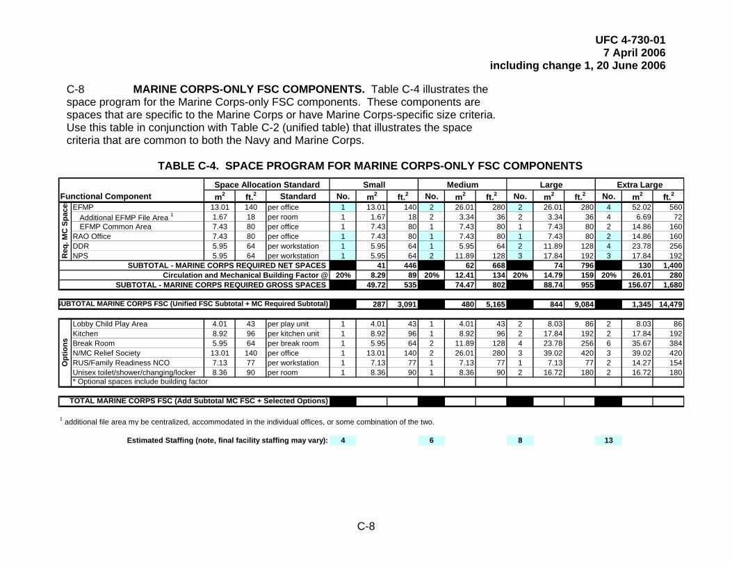
UFC 4-730-01 7 April 2006
including change 1, 20 June 2006
C-8
0.0929nctional Component m2 ft.2 Standard No. m2 ft.2 No. m2 ft.2 No. m2 ft.2 No. m2 ftEFMP 13.01 140 per office 1 13.01 140 2 26.01 280 2 26.01 280 4 52.02
Additional EFMP File Area 1 1.67 18 per room 1 1.67 18 2 3.34 36 2 3.34 36 4 6.69EFMP Common Area 7.43 80 per office 1 7.43 80 1 7.43 80 1 7.43 80 2 14.86
RAO Office 7.43 80 per office 1 7.43 80 1 7.43 80 1 7.43 80 2 14.86DDR 5.95 64 per workstation 1 5.95 64 1 5.95 64 2 11.89 128 4 23.78NPS 5.95 64 per workstation 1 5.95 64 2 11.89 128 3 17.84 192 3 17.84
SUBTOTAL - MARINE CORPS REQUIRED NET SPACES 41 446 62 668 74 796 130 1,4 Circulation and Mechanical Building Factor @ 20% 8.29 89 20% 12.41 134 20% 14.79 159 20% 26.01
SUBTOTAL - MARINE CORPS REQUIRED GROSS SPACES 49.72 535 74.47 802 88.74 955 156.07 1,6
287 3,091 480 5,165 844 9,084 1,345 14,4
Lobby Child Play Area 4.01 43 per play unit 1 4.01 43 1 4.01 43 2 8.03 86 2 8.03Kitchen 8.92 96 per kitchen unit 1 8.92 96 1 8.92 96 2 17.84 192 2 17.84Break Room 5.95 64 per break room 1 5.95 64 2 11.89 128 4 23.78 256 6 35.67N/MC Relief Society 13.01 140 per office 1 13.01 140 2 26.01 280 3 39.02 420 3 39.02RUS/Family Readiness NCO 7.13 77 per workstation 1 7.13 77 1 7.13 77 1 7.13 77 2 14.27Unisex toilet/shower/changing/locker 8.36 90 per room 1 8.36 90 1 8.36 90 2 16.72 180 2 16.72
ea m
Fu .2560
72160160256192
00280
80
79
86192384420154180
1 additional file ar y be centralized, accommodated in the individual offices, or some combination of the two.
Estimated Staffing (note, final facility staffing may vary): 4 6 8 13
C-8 MARINE CORPS-ONLY FSC COMPONENTS. Table C-4 illustrates the space program for the Marine Corps-only FSC components. These components are spaces that are specific to the Marine Corps or have Marine Corps-specific size criteria. Use this table in conjunction with Table C-2 (unified table) that illustrates the space criteria that are common to both the Navy and Marine Corps.
TABLE C-4. SPACE PROGRAM FOR MARINE CORPS-ONLY FSC COMPONENTS
Req
. MC
Spa
ces
TOTAL MARINE CORPS FSC (Add Subtotal MC FSC + Selected Options)
SUB
Opt
ions
TOTAL MARINE CORPS FSC (Unified FSC Subtotal + MC Required Subtotal)
* Optional spaces include building factor
Extra LargeLargeSmallSpace Allocation Standard Medium

UFC 4-730-01 7 April 2006
including change 1, 20 June 2006
C-9 AIR FORCE SPACE CRITERIA. The space criteria for Air Force FSCs are provided in AFH 32-1084. Table C-5 illustrates the space criteria for some potential additional spaces that are not included in AFH 32-1084 and includes the potential quantity range of the spaces.
TABLE C-5. AIR FORCE ADDITIONAL SPACES 0.0929
Functional Component m2 ft.2 StandardInterview Room 13.94 150 per room 1 to 7Copy/Graphics 5.95 64 per room 1 to 5Air Force Aid Society 13.94 150 per office 1RUS/Family Readiness NCO 13.94 150 per workstation 1 to 2Shower/changing/locker area 5.57 60 per ADA shower/changing 0 to 5
Quantity RangeSpace Allocation Standard
C-9


