Familiarization with PC Components - NSC Network · PDF fileFamiliarization with PC Components...
93
COMPUTER HARDWARE AND NETWORKING LAB ( R707) Dept of CSE 1 SNGCE KADAIRIPPU Familiarization with PC Components 1Diagnostic S/Ws, Cards, Design & Programming of add-on cards familiarization with Device drivers, Micro controllers etc. 2Experiments for communication with peripheral devices using C and MASM. 3Experiments for serial and parallel port communication using C and MASM. 4Familiarizing with network configuration (routing, DNS, File Servers etc…). 5LAN trouble shooting, Network problems and recovery, Network diagnostics softwares. References 1Upgrading & Repairing PC’ s - Scott Muller (PHI) 2Red hat Linux Bible- Cristofer Negas (IDG Books) 3TCP/IP Bible –Rob Scringer (IDG Books)
Transcript of Familiarization with PC Components - NSC Network · PDF fileFamiliarization with PC Components...

COMPUTER HARDWARE AND NETWORKING LAB ( R707)
Dept of CSE 1 SNGCE KADAIRIPPU
Familiarization with PC Components
1Diagnostic S/Ws, Cards, Design & Programming of add-on cards familiarization with
Device drivers, Micro controllers etc.
2Experiments for communication with peripheral devices using C and MASM.
3Experiments for serial and parallel port communication using C and MASM.
4Familiarizing with network configuration (routing, DNS, File Servers etc…).
5LAN trouble shooting, Network problems and recovery, Network diagnostics
softwares.
References 1Upgrading & Repairing PC’ s - Scott Muller (PHI)
2Red hat Linux Bible- Cristofer Negas (IDG Books)
3TCP/IP Bible –Rob Scringer (IDG Books)

COMPUTER HARDWARE AND NETWORKING LAB ( R707)
Dept of CSE 2 SNGCE KADAIRIPPU
Cycle 1: PC – Assembling, Installation and Troubleshooting.
1Familiarization of Hardware components.
2Assembling of a PC.
3Familiarization of DOS Commands.
4Familiarization of Unix/ Linux Commands.
5Partitioning of Hard disk using FDISK.
6Installation of different OS (Windows, Linux,) and Configuration of Hardware
Devices.
Cycle 2: Device Controlling using interrupts through C
1. Display ASCII and SCAN code.
2. Read and Set a FILE attribute.
3. Print a String in the specified location.
4. Check whether the mouse driver is installed are not.
5. Hide and Show the Mouse pointer.
6. Get and Set the position of a mouse pointer.
7. Display the status of mouse buttons.
8. Initialize serial port for communication.
9. Read the partition table of a Hard disk.
Cycle 3: 1Configuration of Windows based File and Printer Server.
2Configuration of DNS Server.
COMPUTER HARDWARE AND NETWORKING LAB ( R707)
Dept of CSE 3 SNGCE KADAIRIPPU
Ex 01
:
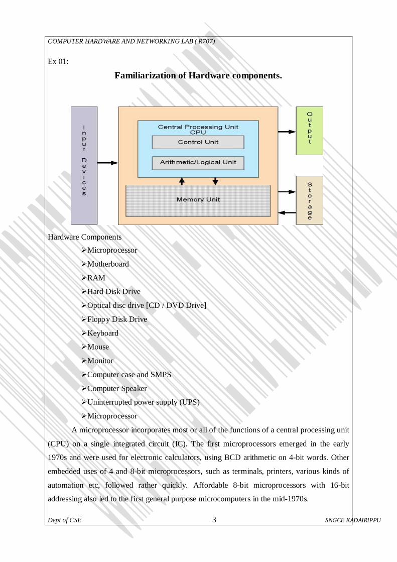
Familiarization of Hardware components.
Hardware Components
Microprocessor
Motherboard
RAM
Hard Disk Drive
Optical disc drive [CD / DVD Drive]
Floppy Disk Drive
Keyboard
Mouse
Monitor
Computer case and SMPS
Computer Speaker
Uninterrupted power supply (UPS)
Microprocessor
A microprocessor incorporates most or all of the functions of a central processing unit
(CPU) on a single integrated circuit (IC). The first microprocessors emerged in the early
1970s and were used for electronic calculators, using BCD arithmetic on 4-bit words. Other
embedded uses of 4 and 8-bit microprocessors, such as terminals, printers, various kinds of
automation etc, followed rather quickly. Affordable 8-bit microprocessors with 16-bit
addressing also led to the first general purpose microcomputers in the mid-1970s.
COMPUTER HARDWARE AND NETWORKING LAB ( R707)
Dept of CSE 4 SNGCE KADAIRIPPU
Processors were for a long period constructed out of small and medium-scale ICs
containing the equivalent of a few to a few hundred transistors. The integration of the whole
CPU onto a single VLSI chip therefore greatly reduced the cost of processing capacity. From
their humble beginnings, continued increases in microprocessor capacity have rendered other
forms of computers almost completely obsolete (see history of computing hardware), with
one or more microprocessor as processing element in everything from the smallest embedded
systems and handheld devices to the largest mainframes and supercomputers.
Since the early 1970s, the increase in processing capacity of evolving microprocessors
has been known to generally follow Moore's Law. It suggests that the complexity of an
integrated circuit, with respect to minimum component cost, doubles every 18 months.
8-bit designs
The 4004 was later followed in 1972 by the 8008, the world's first 8-bit
microprocessor. These processors are the precursors to the very successful Intel 8080 (1974),
Zilog Z80 (1976), and derivative Intel 8-bit processors. The competing Motorola 6800 was
released August 1974. Its architecture was cloned and improved in the MOS Technology
6502 in 1975, rivaling the Z80 in popularity during the 1980s.
16-bit designs
The first multi-chip 16-bit microprocessor was the National Semiconductor IMP-16,
introduced in early 1973. An 8-bit version of the chipset was introduced in 1974 as the IMP-
8. During the same year, National introduced the first 16-bit single-chip microprocessor, the
National Semiconductor PACE, which was later followed by an NMOS version, the
INS8900.
Other early multi-chip 16-bit microprocessors include one used by Digital Equipment
Corporation (DEC) in the LSI-11 OEM board set and the packaged PDP 11/03 minicomputer,
and the Fairchild Semiconductor Micro Flame 9440, both of which were introduced in the
1975 to 1976 time frame.
The first single-chip 16-bit microprocessor was TI's TMS 9900, which was also
compatible with their TI-990 line of minicomputers. The 9900 was used in the TI 990/4
minicomputer, the TI-99/4A home computer, and the TM990 line of OEM microcomputer
boards. The chip was packaged in a large ceramic 64-pin DIP package, while most 8-bit
microprocessors such as the Intel 8080 used the more common, smaller, and less expensive
plastic 40-pin DIP. A follow-on chip, the TMS 9980, was designed to compete with the Intel
8080, had the full TI 990 16-bit instruction set, used a plastic 40-pin package, moved data 8
bits at a time, but could only address 16 KB. A third chip, the TMS 9995, was a new design.

COMPUTER HARDWARE AND NETWORKING LAB ( R707)
Dept of CSE 5 SNGCE KADAIRIPPU
The family later expanded to include the 99105 and 99110.
32-bit designs
16-bit designs were in the markets only briefly when full 32-bit implementations
started to appear.
The most significant of the 32-bit designs is the MC68000, introduced in 1979. The
68K, as it was widely known, had 32-bit registers but used 16-bit internal data paths, and a
16-bit external data bus to reduce pin count, and supported only 24-bit addresses. Motorola
generally described it as a 16-bit processor, though it clearly has 32-bit architecture. The
combination of high speed, large (16 megabytes (2^24)) memory space and fairly low costs
made it the most popular CPU design of its class. The Apple Lisa and Macintosh designs
made use of the 68000, as did a host of other designs in the mid-1980s, including the Atari
ST and Commodore Amiga.
The world's first single-chip fully-32-bit microprocessor, with 32-bit data paths, 32-bit
buses, and 32-bit addresses, was the AT&T Bell Labs BELLMAC-32A, with first samples in
1980, and general production in 1982 (See this bibliographic reference and this general
reference). After the divestiture of AT&T in 1984, it was renamed the WE 32000 (WE for
Western Electric), and had two follow-on generations, the WE 32100 and WE 32200. These
microprocessors were used in the AT&T 3B5 and 3B15 minicomputers; in the 3B2, the
world's first desktop super microcomputer; in the "Companion", the world's first 32-bit laptop
computer; and in "Alexander", the world's first book-sized super microcomputer, featuring
ROM-pack memory cartridges similar to today's gaming consoles. All these systems ran the
UNIX System V operating system.
Intel's first 32-bit microprocessor was the iAPX 432, which was introduced in 1981
but was not a commercial success. It had an advanced capability-based object-oriented
architecture, but poor performance compared to other competing architectures such as the
Motorola 68000.
64-bit designs in personal computers
While 64-bit microprocessor designs have been in use in several markets since the
early 1990s, the early 2000s saw the introduction of 64-bit microchips targeted at the PC
market.
With AMD's introduction of a 64-bit architecture backwards-compatible with x86,
x86-64 (now called AMD64), in September 2003, followed by Intel's fully compatible 64-bit
extensions (first called IA-32e or EM64T, later renamed Intel 64), the 64-bit desktop era
began. Both versions can run 32-bit legacy applications without any speed penalty as well as
COMPUTER HARDWARE AND NETWORKING LAB ( R707)
Dept of CSE 6 SNGCE KADAIRIPPU
new 64-bit software. With operating systems Windows XP x64, Windows Vista x64, Linux,
BSD and Mac OS X that run 64-bit native, the software too is geared to utilize the full power
of such processors. The move to 64 bits is more than just an increase in register size from the
IA-32 as it also doubles the number of general-purpose registers.
The move to 64 bits by PowerPC processors had been intended since the processors'
design in the early 90s and was not a major cause of incompatibility. Existing integer
registers are extended as are all related data pathways, but, as was the case with IA-32, both
floating point and vector units had been operating at or above 64 bits for several years. Unlike
what happened with IA-32 was extended to x86-64, no new general purpose registers were
added in 64-bit PowerPC, so any performance gained when using the 64-bit mode for
applications making no use of the larger address space is minimal.
Multicore designs
A different approach to improving a computer's performance is to add extra
processors, as in symmetric multiprocessing designs which have been popular in servers and
workstations since the early 1990s. Keeping up with Moore's Law is becoming increasingly
challenging as chip-making technologies approach the physical limits of the technology.
In response, the microprocessor manufacturers look for other ways to improve
performance, in order to hold on to the momentum of constant upgrades in the market. A
multi-core processor is simply a single chip containing more than one microprocessor core,
effectively multiplying the potential performance with the number of cores (as long as the
operating system and software is designed to take advantage of more than one processor).
Some components, such as bus interface and second level cache, may be shared between
cores. Because the cores are physically very close they interface at much faster clock speeds
compared to discrete multiprocessor systems, improving overall system performance.
In 2005, the first mass-market dual-core processors were announced and as of 2007
dual-core processors are widely used in servers, workstations and PCs while quad-core
processors are now available for high-end applications in both the home and professional
environments.
Sun Microsystems has released the Niagara and Niagara 2 chips, both of which
feature an eight-core design. The Niagara 2 supports more threads and operates at 1.6 GHz.
High-end Intel Xeon processors that are on the LGA771 socket are DP (dual
processor) capable, as well as the new Intel Core 2 Extreme QX9775 also used in the Mac
Pro by Apple and the Intel Skull trail motherboard.
COMPUTER HARDWARE AND NETWORKING LAB ( R707)
Dept of CSE 7 SNGCE KADAIRIPPU
➢ Motherboard
A motherboard is the central or primary printed circuit board (PCB) making up a
complex electronic system, such as a modern computer. It is also known as a mainboard,
baseboard, system board, planar board, or, on Apple computers, a logic board, and is
sometimes abbreviated casually as mobo.
Most motherboards produced today are designed for so-called IBM-compatible
computers, which held over 96% of the global personal computer market in
2005.Motherboards for IBM-compatible computers are specifically covered in the PC
motherboard article.
A motherboard, like a backplane, provides the electrical connections by which the
other components of the system communicate, but unlike a backplane also contains the
central processing unit and other subsystems such as real time clock, and some peripheral
interfaces.
A typical desktop computer is built with the microprocessor, main memory, and other
essential components on the motherboard. Other components such as external storage,
controllers for video display and sound, and peripheral devices are typically attached to the
motherboard via edge connectors and cables, although in modern computers it is increasingly
common to integrate these "peripherals" into the motherboard.
Components and functions
The 2004 K7VT4A Pro motherboard by ASRock. The chipset on this board consists
of northbridge and southbridge chips.
The motherboard of a typical desktop consists of a large printed circuit board. It holds
electronic components and interconnects, as well as physical connectors (sockets, slots, and
headers) into which other computer components may be inserted or attached.
Most motherboards include, at a minimum:
←sockets (or slots) in which one or more microprocessors (CPUs) are installed
←slots into which the system's main memory is installed (typically in the form of DIMM
modules containing DRAM chips)
←a chipset which forms an interface between the CPU's front-side bus, main memory, and
peripheral buses
←non-volatile memory chips (usually Flash ROM in modern motherboards) containing the
system's firmware or BIOS
←a clock generator which produces the system clock signal to synchronize the various

COMPUTER HARDWARE AND NETWORKING LAB ( R707)
Dept of CSE 8 SNGCE KADAIRIPPU
components
←slots for expansion cards (these interface to the system via the buses supported by the
chipset)
←power connectors and circuits, which receive electrical power from the computer power
supply and distribute it to the CPU, chipset, main memory, and expansion cards.
Additionally, nearly all motherboards include logic and connectors to support
commonly-used input devices, such as PS/2 connectors for a mouse and keyboard. Early
personal computers such as the Apple II or IBM PC included only this minimal peripheral
support on the motherboard. Occasionally video interface hardware was also integrated into
the motherboard; for example on the Apple II, and rarely on IBM-compatible computers such
as the IBM PC Jr. Additional peripherals such as disk controllers and serial ports were
provided as expansion cards.
Given the high thermal design power of high-speed computer CPUs and components,
modern motherboards nearly always include heat sinks and mounting points for fans to
dissipate excess heat.
Integrated peripherals
With the steadily declining costs and size of integrated circuits, it is now possible
to include support for many peripherals on the motherboard. By combining many
functions on one PCB, the physical size and total cost of the system may be reduced;
highly-integrated motherboards are thus especially popular in small form factor and
budget computers.
For example, the ECS RS485M-M,a typical modern budget motherboard for
computers based on AMD processors, has on-board support for a very large range of
peripherals:
←disk controllers for a floppy disk drive, up to 2 PATA drives, and up to 6 SATA drives
(including RAID 0/1 support)
←integrated ATI Radeon graphics controller supporting 2D and 3D graphics, with VGA and
TV output
←integrated sound card supporting 8-channel (7.1) audio and S/PDIF output
←fast Ethernet network controller for 10/100 Mbit networking
←USB 2.0 controller supporting up to 12 USB ports
←IrDA controller for infrared data communication (e.g. with an IrDA enabled Cellular Phone

COMPUTER HARDWARE AND NETWORKING LAB ( R707)
Dept of CSE 9 SNGCE KADAIRIPPU
or Printer) temperature, voltage, and fan-speed sensors that allow software to monitor the
health of computer components.
←
←➢ RAM [ Random access memory]
←Random access memory (usually known by its acronym, RAM) is a type of
computer data storage. Today it takes the form of integrated circuits that allow the
stored data to be accessed in any order, i.e. at random. The word random thus refers to
the fact that any piece of data can be returned in a constant time, regardless of its
physical location and whether or not it is related to the previous piece of data.
←This contrasts with storage mechanisms such as tapes, magnetic discs and optical
discs, which rely on the physical movement of the recording medium or a reading
head. In these devices, the movement takes longer than the data transfer, and the
retrieval time varies depending on the physical location of the next item.
←The word RAM is mostly associated with volatile types of memory (such as
DRAM memory modules), where the information is lost after the power is switched
off. However, many other types of memory are RAM as well (i.e. Random Access
Memory), including most types of ROM and a kind of flash memory called NOR-
Flash.
Types of RAM
SRAM (Static RAM)
DRAM (Dynamic RAM)
FPM (Fast Page Mode DRAM)
EDO RAM (Extended Data Out DRAM)
BEDO RAM (Burst Extended Data Out DRAM)
SDRAM (Synchronous DRAM)
o DDR SDRAM (Double Data Rate SDRAM)
o DDR2 SDRAM
o DDR3 SDRAM
o Rambus DRAM
XDR DRAM
➢ Hard Disk Drive
A hard disk drive (HDD), commonly referred to as a hard drive, hard disk, or fixed
disk drive, is a non-volatile storage device which stores digitally encoded data on rapidly

COMPUTER HARDWARE AND NETWORKING LAB ( R707)
Dept of CSE 10 SNGCE KADAIRIPPU
rotating platters with magnetic surfaces. Strictly speaking, "drive" refers to a device distinct
from its medium, such as a tape drive and its tape, or a floppy disk drive and its floppy disk.
Early HDDs had removable media; however, an HDD today is typically a sealed unit (except
for a filtered vent hole to equalize air pressure) with fixed media.
Technology
HDDs record data by magnetizing ferromagnetic material directionally, to represent
either a 0 or a 1 binary digit. They read the data back by detecting the magnetization of the
material. A typical HDD design consists of a spindle which holds one or more flat circular
disks called platters, onto which the data are recorded. The platters are made from a non-
magnetic material, usually aluminum alloy or glass, and are coated with a thin layer of
magnetic material. Older disks used iron(III) oxide as the magnetic material, but current disks

COMPUTER HARDWARE AND NETWORKING LAB ( R707)
Dept of CSE 11 SNGCE KADAIRIPPU
use a cobalt-based alloy.
The platters are spun at very high speeds. Information is written to a platter as it
rotates past devices called read-and-write heads that operate very close (tens of nanometers in
new drives) over the magnetic surface. The read-and-write head is used to detect and modify
the magnetization of the material immediately under it. There is one head for each magnetic
platter surface on the spindle, mounted on a common arm. An actuator arm (or access arm)
moves the heads on an arc (roughly radially) across the platters as they spin, allowing each
head to access almost the entire surface of the platter as it spins. The arm is moved using a
voice coil actuator or (in older designs) a stepper motor. Stepper motors were outside the
head-disk chamber, and preceded voice-coil drives. The latter, for a while, had a structure
similar to that of a loudspeaker; the coil and heads moved in a straight line, along a radius of
the platters. The present-day structure differs in several respects from that of the earlier voice-
coil drives, but the same interaction between the coil and magnetic field still applies, and the
term is still used.
Older drives read the data on the platter by sensing the rate of change of the
magnetism in the head; these heads had small coils, and worked (in principle) much like
magnetic-tape playback heads, although not in contact with the recording surface. As data
density increased, read heads using magnetoresistance (MR) came into use; the electrical
resistance of the head changed according to the strength of the magnetism from the platter.
Later development made use of spintronics; in these heads, the magnetoresistive effect was
much greater that in earlier types, and was dubbed "giant" magnetoresistance (GMR). This
refers to the degree of effect, not the physical size, of the head — the heads themselves are
extremely tiny, and are too small to be seen without a microscope. GMR read heads are now
commonplace.[citation needed]
HD heads are kept from contacting the platter surface by the air that is extremely close
to the platter; that air moves at, or close to, the platter speed.[citation needed] The record and
playback head are mounted on a block called a slider, and the surface next to the platter is
shaped to keep it just barely out of contact. It's a type of air bearing.
The magnetic surface of each platter is conceptually divided into many small sub-
micrometre-sized magnetic regions, each of which is used to encode a single binary unit of
information. In today's HDDs, each of these magnetic regions is composed of a few hundred
magnetic grains. Each magnetic region forms a magnetic dipole which generates a highly
localized magnetic field nearby. The write head magnetizes a region by generating a strong
local magnetic field. Early HDDs used an electromagnet both to generate this field and to

COMPUTER HARDWARE AND NETWORKING LAB ( R707)
Dept of CSE 12 SNGCE KADAIRIPPU
read the data by using electromagnetic induction. Later versions of inductive heads included
metal in Gap (MIG) heads and thin film heads. In today's heads, the read and write elements
are separate, but in close proximity, on the head portion of an actuator arm. The read element
is typically magneto-resistive while the write element is typically thin-film inductive.
In modern drives, the small size of the magnetic regions creates the danger that their
magnetic state might be lost because of thermal effects. To counter this, the platters are
coated with two parallel magnetic layers, separated by a 3-atom-thick layer of the non-
magnetic element ruthenium, and the two layers are magnetized in opposite orientation, thus
reinforcing each other. Another technology used to overcome thermal effects to allow greater
recording densities is perpendicular recording, first shipped in 2005, as of 2007 the
technology was used in many HDDs.
➢ Optical disc drive
An optical disc drive (ODD) is a disk drive that uses laser light or electromagnetic
waves near the light spectrum as part of the process of reading and writing data. It is a
computer's peripheral device, that stores data on optical discs. Some drives can only read
from discs, but commonly drives are both readers and recorders. Recorders are sometimes
called burners or writers.
Common media and technology families include CD, DVD, and Blu-ray Disc.
Standalone, non-computer, optical storage devices also exist, for example popular CD
players, DVD players, and some DVD recorders, but those are not covered in this article.
Optical disc drives are generally used for small-scale archival or data exchange, being slower
and more materially expensive per unit than the moulding process used to mass-manufacture
pressed discs. But they—along with flash memory—have displaced floppy disk drives and
magnetic tape drives in most cases because of the low cost of optical media and the near-
ubiquity of optical drives in computers and consumer entertainment hardware.
Laser and optics
The most important part of an optical disc drive is an optical path, placed in a pickup
head (PUH), usually consisting of semiconductor laser, a lense for guiding the laser beam,
and photodiodes detecting the light reflection from disc's surface.
Initially, CD lasers with a wavelength of 780 nm were used, being within infrared
range. For DVDs, the wavelength was reduced to 650 nm (red color), and the wavelength for
Blu-Ray Disc was reduced to 405 nm (blue color).
Two main servomechanisms are used, the first one to maintain a correct distance

COMPUTER HARDWARE AND NETWORKING LAB ( R707)
Dept of CSE 13 SNGCE KADAIRIPPU
between lens and disc, and ensure the laser beam is focused on a small laser spot on the disc.
The second servo moves a head along the disc's radius, keeping the beam on a groove, a
continuous spiral data path.
On read only media (ROM), during the manufacturing process the groove, made of
pits, is pressed on a flat surface, called land. Because the depth of the pits is approximately
one-quarter to one-sixth of the laser's wavelength, the reflected beam's phase is shifted in
relation to the incoming reading beam, causing mutual destructive interference and reducing
the reflected beam's intensity. This is detected by photodiodes that output electrical signals.
A recorder encodes (or burns) data onto a recordable CD-R, DVD-R, DVD+R, or BD-
R disc (called a blank) by selectively heating parts of an organic dye layer with a
laser[citation needed]. This changes the reflectivity of the dye, thereby creating marks that
can be read like the pits and lands on pressed discs. For recordable discs, the process is
permanent and the media can be written to only once. While the reading laser is usually not
stronger than 5 mW, the writing laser is considerably more powerful. The higher writing
speed, the less time a laser has to heat a point on the media, thus its power has to increase
proportionally.[citation needed] DVD burner's laser often peaks at about 100 mW in
continuous wave, and 225 mW pulsed.
For rewriteable CD-RW, DVD-RW, DVD+RW, DVD-RAM, or BD-RE media, the
laser is used to melt a crystalline metal alloy in the recording layer of the disc. Depending on
the amount of power applied, the substance may be allowed to melt back (change the phase
back) into crystalline form or left in an amorphous form, enabling marks of varying
reflectivity to be created.
Double-sided media may be used, but they are not easily accessed with a standard
drive, as they require to be physically reverted to access the data on the other side.
Double layer (DL) media have two independent data layers separated by a semi-
reflective layer. Both layers are accessible from the same side, but require the optics to
change the laser's focus. Traditional single layer (SL) writable media are produced with a
spiral groove molded in the protective polycarbonate layer (not in the data recording layer), to
lead and synchronize the speed of recording head. Double-layered writable media have: a
first polycarbonate layer with a (shallow) groove, a first data layer, a semi-reflective layer, a
second (spacer) polycarbonate layer with another (deep) groove, and a second data layer. The
first groove spiral usually starts on the inner edge and extends outerwards, while the second
groove starts on the outer edge and extends inwards.

COMPUTER HARDWARE AND NETWORKING LAB ( R707)
Dept of CSE 14 SNGCE KADAIRIPPU
➢ Floppy Disk Drive
A floppy disk is a data storage medium that is composed of a disk of thin, flexible
("floppy") magnetic storage medium encased in a square or rectangular plastic shell. Floppy
disks are read and written by a floppy disk drive or FDD, the initials of which should not be
confused with "fixed disk drive", which is another term for an hard disk drive. Invented by
IBM, floppy disks in 8-inch (200 mm), 5¼-inch (133⅓ mm), and the newest and most
common 3½-inch (90 mm) formats enjoyed many years as a popular and ubiquitous form of
data storage and exchange, from the mid-1970s to the late 1990s.
➢ Keyboard
A keyboard is an arrangement of buttons, or keys. A keyboard typically has characters
engraved or printed on the keys; in most cases, each press of a key corresponds to a single
written symbol. However, to produce some symbols requires pressing and holding several
keys simultaneously or in sequence; other keys do not produce any symbol, but instead affect
the operation of the computer or the keyboard itself.
A majority of all keyboard keys produce letters, numbers or signs (characters) that are
appropriate for the operator's language. Other keys can produce actions when pressed, and
other actions are available by the simultaneous pressing of more than one action key.
Keyboards with extra keys Multimedia keyboards
Multimedia keyboards offer special keys for accessing music, web, and other oft-used
programs. They also usually have other convenient controls, such as a mute button, volume
buttons or knob, and standby (sleep) button. Gaming keyboards
Some gaming keyboards offer extra function keys which can be programmed with
keystroke macros. For example, ctrl+shift+y could be a keystroke that is frequently used in a
certain computer game. But it is a physically awkward (or, at least, annoying) combination
for the hands to reach for repeatedly. It may be very useful to assign that keystroke
combination to one function key. Some keyboards (Such as the Logitech G11 or G15) have a
keypad full of "G keys" to the left of the QWERTY keyboard for this purpose. The keystroke
macros can be reprogrammed at will.
The development of these keyboards was spurred by gaming, but the concept can also
be very convenient in non-gaming applications, such as office work. Any keystroke
combination that is awkward or annoying but frequently needed can be replaced with a "G
key". The meaning of the "G key" press can automatically change depending on which

COMPUTER HARDWARE AND NETWORKING LAB ( R707)
Dept of CSE 15 SNGCE KADAIRIPPU
application has focus, thus extending the number of macros available given a certain limited
number of G keys.
Virtual keyboards
A relatively new type of keyboard, the I-Tech Virtual Laser Keyboard, works by
projecting an image of a full-size keyboard onto a surface. Sensors in the projection unit
identify which key is being "pressed" and relay the signals to a computer or personal digital
assistant. There is also a virtual keyboard, the On-Screen Keyboard, for use on Windows, and
possibly on Mac; although the one on Mac is not confirmed. To access the On-Screen
Keyboard...
Win '95 to 2000 Go to the Start menu, or hit the Windows key; and go to Programs, then
Accessories, then Accessibility; then to On-Screen Keyboard.
Windows XP and Vista Go to the Start menu, and click On-Screen Keyboard only if
you've recently used it. If you did not use it recently, press the Windows key or click "Start"
(Vista replaces this with a circular Windows logo) and choose "All Programs", then
Accessories, then Accessibility; and then On-Screen Keyboard. Touchscreen keyboards
One can use a computer screen with touchscreen functionality as a keyboard, such as
with the iPhone and OLPC laptop. (The OLPC initiative's second computer will be
effectively two tablet touchscreens hinged together like a book. It can be used as a
convertible tablet PC where the keyboard is one half-screen (one side of the book) which
turns into a touchscreen virtual keyboard.) Such keyboards may result in a slower typing rate
(WPM) for fast typists, but there is insufficient research to tell how typing would be
hampered for average versus fast typers.
➢ Mouse
A mouse (plural mice, mouse devices, or mouses) is a pointing device that functions by
detecting two-dimensional motion relative to its supporting surface. Physically, a mouse
consists of a small case, held under one of the user's hands, with one or more buttons. It
sometimes features other elements, such as "wheels", which allow the user to perform various
system-dependent operations, or extra buttons or features can add more control or
dimensional input. The mouse's motion typically translates into the motion of a pointer on a
display, which allows for fine control of a Graphical User Interface.
The name mouse, originated at the Stanford Research Institute, derives from the resemblance
of early models (which had a cord attached to the rear part of the device, suggesting the idea
of a tail) to the common mouse.

COMPUTER HARDWARE AND NETWORKING LAB ( R707)
Dept of CSE 16 SNGCE KADAIRIPPU
The first marketed integrated mouse — shipped as a part of a computer and intended for
personal computer navigation — came with the Xerox 8010 Star Information System in 1981.
Technologies
Mechanical mice
Bill English, builder of Engelbart's original mouse, invented the so-called ball mouse in 1972
while working for Xerox PARC. The ball-mouse replaced the external wheels with a single
ball that could rotate in any direction. It came as part of the hardware package of the Xerox
Alto computer. Perpendicular chopper wheels housed inside the mouse's body chopped
beams of light on the way to light sensors, thus detecting in their turn the motion of the ball.
This variant of the mouse resembled an inverted trackball and became the predominant form
used with personal computers throughout the 1980s and 1990s. The Xerox PARC group also
settled on the modern technique of using both hands to type on a full-size keyboard and
grabbing the mouse when required.
The ball mouse utilizes two rollers rolling against two sides of the ball. One roller detects the
horizontal motion of the mouse and other the vertical motion. The motion of these two rollers
causes two disc-like encoder wheels to rotate, interrupting optical beams to generate electrical
signals. The mouse sends these signals to the computer system by means of connecting wires.
The driver software in the system converts the signals into motion of the mouse pointer along
X and Y axes on the screen.
Mechanical or opto-mechanical
A mouse described as simply "mechanical" has a contact-based incremental rotary
encoder, [citation needed] a system prone to drag and unreliability of contact. Opto-
mechanical mice still use a ball or crossed wheels, but detect shaft rotation using an optical
encoder with lower friction and more certain performance.
Optical mice
An optical mouse uses a light-emitting diode and photodiodes to detect movement
relative to the underlying surface, rather than moving some of its parts — as in a
mechanical mouse.
➢ Computer case with Power supply
A computer case is the enclosure that contains the main components of a computer.
Cases are usually constructed from steel, aluminium, or plastic, although other materials such
as wood, plexiglas or fans have also been used in case designs. Cases can come in many
different sizes, or form factors. The size and shape of a computer case is usually determined
COMPUTER HARDWARE AND NETWORKING LAB ( R707)
Dept of CSE 17 SNGCE KADAIRIPPU
by the form factor of the motherboard that it is designed to accommodate, since this is the
largest and most central component of most computers. Consequently, personal computer
form factors typically specify only the internal dimensions and layout of the case. Form
factors for rack-mounted and blade servers may include precise external dimensions as well,
since these cases must themselves fit in specific enclosures.
Currently, the most popular form factor for desktop computers is ATX, although
microATX and small form factors have become very popular for a variety of uses.
Companies like Shuttle Inc. and AOpen have popularized small cases, for which FlexATX is
the most common motherboard size. Apple Computer has also produced the Mac Mini
computer, which is similar in size to a standard CD-ROM drive.
A switched-mode power supply, switching-mode power supply or SMPS, is an
electronic power supply unit (PSU) that incorporates a switching regulator. While a linear
regulator maintains the desired output voltage by dissipating excess power in a "pass" power
transistor, the SMPS rapidly switches a power transistor between saturation (full on) and
cutoff (completely off) with a variable duty cycle whose average is the desired output
voltage. The resulting rectangular waveform is low-pass filtered with an inductor and
capacitor. The main advantage of this method is greater efficiency because the switching
transistor dissipates little power in the saturated state and the off state compared to the
semiconducting state (active region). Other advantages include smaller size and lighter
weight (from the elimination of low frequency transformers which have a high weight) and
lower heat generation from the higher efficiency. Disadvantages include greater complexity,
the generation of high amplitude, high frequency energy that the low-pass filter must block to
avoid electromagnetic interference (EMI), and a ripple voltage at the switching frequency and
the harmonic frequencies thereof.
➢ Computer Speaker
Computer speakers, or multimedia speakers, are external speakers, commonly
equipped with a low-power internal amplifier. The standard audio connection is a 3.5mm (1/8
inch) stereo jack plug often colour-coded lime green (following the PC 99 standard) for
computer sound cards.A plug and socket for a two-wire (signal and ground) coaxial cable that
is widely used to connect analog audio and video components. Also called a "phono
connector," rows of RCA sockets are found on the backs of stereo amplifiers and numerous
A/V products. The prong is 1/8" thick by 5/16" long. A few use an RCA connector for input.
There are also USB speakers which are powered from the 5 volts at 200 milliamps provided

COMPUTER HARDWARE AND NETWORKING LAB ( R707)
Dept of CSE 18 SNGCE KADAIRIPPU
by the USB port, allowing about half a watt of output power.
Computer speakers range widely in quality and in price. The computer speakers
typically packaged with computer systems are small plastic boxes with mediocre sound
quality. Some of the slightly better computer speakers have equalization features such as bass
and treble controls, improving their sound quality somewhat.
The internal amplifiers require an external power source, known as a 'wall-wart'. More
sophisticated computer speakers may have a 'subwoofer' unit, to enhance bass output, and
these units usually include the power amplifiers both for the bass speaker, and the small
'satellite' speakers.
➢ Uninterruptible power supply (UPS)
An uninterruptible power supply (UPS), also known as a continuous power supply
(CPS) or a battery backup is a device which maintains a continuous supply of electric power
to connected equipment by supplying power from a separate source when utility power is
not available. It differs from an auxiliary power supply or standby generator, which does not
provide instant protection from a momentary power interruption, however could be used to
provide uninterrupted power to equipment for 1 - 20 minutes until a generator can be turned
on. Integrated systems that have UPS and standby generator components are often referred
to as emergency power systems.
There are three distinct UPS types :
• off-line : remains idle until a power failure occurs, and then switches from utility power to
its own power source, almost instantaneously.
• line-interactive.
• on-line : continuously powers the protected load from its energy reserves stored in a lead-
acid battery or flywheel, while simultaneously replenishing the reserves from the AC
power. It also provides protection against all common power problems, and for this reason
it is also known as a power conditioner and a line conditioner.
COMPUTER HARDWARE AND NETWORKING LAB ( R707)
Dept of CSE 19 SNGCE KADAIRIPPU
Ex No 2
If you have purchased all the necessary hardware your are ready assemble your PC.
Assembling of a PC.
Motherboard Installation.
The first thing you should do is unpack your ATX case. Take off the cover of your
case so that you can access the inside. Place the case on a desk so that you are looking down
towards the open case. Your case should come with motherboard mounting screws. If your
ATX back plate it not already fitted you can fit it by placing your plate near the ATX back
plate cut out and pushing the plate outwards, it should clip on.
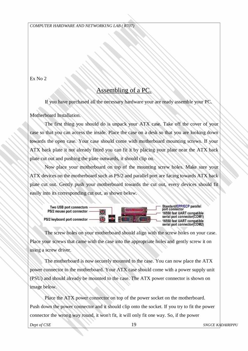
Now place your motherboard on top of the mounting screw holes. Make sure your
ATX devices on the motherboard such as PS/2 and parallel port are facing towards ATX back
plate cut out. Gently push your motherboard towards the cut out, every devices should fit
easily into its corresponding cut out, as shown below.
The screw holes on your motherboard should align with the screw holes on your case.
Place your screws that came with the case into the appropriate holes and gently screw it on
using a screw driver.
The motherboard is now securely mounted to the case. You can now place the ATX
power connector to the motherboard. Your ATX case should come with a power supply unit
(PSU) and should already be mounted to the case. The ATX power connector is shown on
image below.
Place the ATX power connector on top of the power socket on the motherboard.
Push down the power connector and it should clip onto the socket. If you try to fit the power
connector the wrong way round, it won't fit, it will only fit one way. So, if the power

COMPUTER HARDWARE AND NETWORKING LAB ( R707)
Dept of CSE 20 SNGCE KADAIRIPPU
connector does not go in, it should go in the other way round.
Processor (CPU) Installation
Locate the processor socket on your motherboard. I am installing an Intel PIII 866
processor on a socket 370 as shown on the following image. The installation would be
slightly different if you have a different processor i.e. Slot1 PIII CPU, P4 Socket 478, Core 2
Duo Socket 775, AMD Slot A / Socket A, Socket AM2 CPU etc.
Raise the brown lever on the socket and slowly put the processor in place. You have
to make sure the pin 1 of your CPU goes into the pin 1 of your CPU socket otherwise the
CPU would not get into the socket, so don't try to force it in. It will go in gently if you fit it
correctly. Now close the brown lever which will securely hold the CPU in place. If you
bought a retail boxed CPU it would include a heatsink + fan. If you bought an OEM CPU
make sure you got a fan that is correct for the speed of your CPU, otherwise your CPU will
overheat and behave abnormally or could be damaged. Take off the plastic cover from the
bottom of the CPU fan that covers the heat transfer pad. Now place the CPU fan on top the
CPU and push down the metal clips on the fan so that it clips onto the CPU socket. CPU fan
has a power connector which needs to be connected to CPU fan power socket on your
motherboard as shown on the image above.
Finally, you have to specify what frequency (speed) your CPU is running at. This can be done
using jumper settings, or on some modern motherboard it can be done in the BIOS, or your
motherboard may have automatic detection for your CPU frequency. Please refer to your
motherboard manual for more details. The motherboard I am using (Abit BX133) has a dip-
stick jumper setting and it can be setup in the BIOS. I have left the jumper setting to default
as I will use the BIOS to specify the CPU frequency. The CPU runs at the bus speed of
133Mhz therefore I will use the settings 133 * 6.5(multiplier) under the BIOS, which will the
run the CPU at 866Mhz.
Memory Installation
Installing memory is quite simple. Find the RAM banks on your motherboard, they
should look similar to the banks below. Notice the memory banks has a white clip on each
side. Make sure you release the clips so it bends to each side.
Hold each corner of the RAM placing it on top of the bank 1. You will notice that the
RAM has a cut at the bottom side, it is there to prevent the memory going in the wrong way
round. If you are holding the RAM the incorrect way you will not be able insert it. Gently
COMPUTER HARDWARE AND NETWORKING LAB ( R707)
Dept of CSE 21 SNGCE KADAIRIPPU
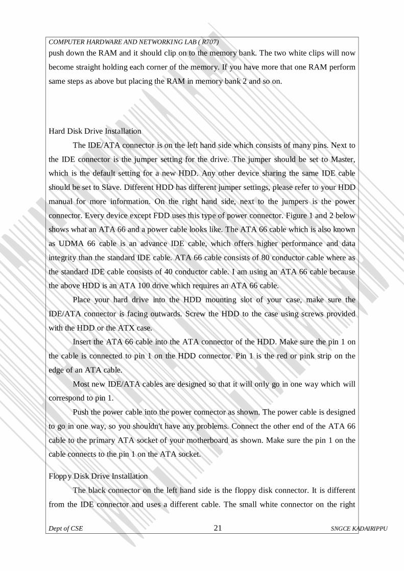
push down the RAM and it should clip on to the memory bank. The two white clips will now
become straight holding each corner of the memory. If you have more that one RAM perform
same steps as above but placing the RAM in memory bank 2 and so on.
Hard Disk Drive Installation
The IDE/ATA connector is on the left hand side which consists of many pins. Next to
the IDE connector is the jumper setting for the drive. The jumper should be set to Master,
which is the default setting for a new HDD. Any other device sharing the same IDE cable
should be set to Slave. Different HDD has different jumper settings, please refer to your HDD
manual for more information. On the right hand side, next to the jumpers is the power
connector. Every device except FDD uses this type of power connector. Figure 1 and 2 below
shows what an ATA 66 and a power cable looks like. The ATA 66 cable which is also known
as UDMA 66 cable is an advance IDE cable, which offers higher performance and data
integrity than the standard IDE cable. ATA 66 cable consists of 80 conductor cable where as
the standard IDE cable consists of 40 conductor cable. I am using an ATA 66 cable because
the above HDD is an ATA 100 drive which requires an ATA 66 cable.
Place your hard drive into the HDD mounting slot of your case, make sure the
IDE/ATA connector is facing outwards. Screw the HDD to the case using screws provided
with the HDD or the ATX case.
Insert the ATA 66 cable into the ATA connector of the HDD. Make sure the pin 1 on
the cable is connected to pin 1 on the HDD connector. Pin 1 is the red or pink strip on the
edge of an ATA cable.
Most new IDE/ATA cables are designed so that it will only go in one way which will
correspond to pin 1.
Push the power cable into the power connector as shown. The power cable is designed
to go in one way, so you shouldn't have any problems. Connect the other end of the ATA 66
cable to the primary ATA socket of your motherboard as shown. Make sure the pin 1 on the
cable connects to the pin 1 on the ATA socket.
Floppy Disk Drive Installation
The black connector on the left hand side is the floppy disk connector. It is different
from the IDE connector and uses a different cable. The small white connector on the right

COMPUTER HARDWARE AND NETWORKING LAB ( R707)
Dept of CSE 22 SNGCE KADAIRIPPU
hand side is the power connector for the floppy drive. Figure 1 and 2 below shows what a
floppy drive cable and floppy drive power connector looks like.Place the floppy drive into the
FDD mounting slot as shown. Screw the drive securely into place.
Insert the floppy drive cable into the floppy drive connector. Make sure the pin 1 on
the cable connects to the pin 1 on the floppy drive connector. As you already know by now
that pin 1 is the red or
pink strip on the edge of the floppy drive cable. Most floppy drive cables are designed so that
it willonly go in on way, so you can not connect it incorrectly.Push the floppy drive power
cable to the power connector. This will only go in on way.
CD-ROM/DVD-ROM Installation
On the right hand side you have the power connector. Next to power connector you
have the IDE connector. On the left hand side near the IDE connector you have the jumper
settings for the DVD-ROM. The jumper is set to Master by default. I am connecting the
DVD-ROM on a separate IDE cable therefore I will leave the jumper setting to Master.
However if you are sharing an IDE cable with another device like HDD, then you would have
to set jumper to Slave, as your HDD would be set to Master. Next to the jumpers you have
the CD Audio-Out socket. One side of your audio cable connects to this socket and other side
connects to the sound card cd-in socket. This would allow you to listen to Audio CD's on
your computer. Mount your CD/DVD-ROM drive into its mounting slot. Use the supplied
screws to screw the drive into position.
Connect the IDE cable to the drives IDE connector. Make sure the pin 1 on the cable
is connected to pin 1 on the drives IDE connector. Pin 1 is the red or pink strip on the edge of
an IDE cable. Connect the other end of the IDE cable to the IDE socket on your motherboard
as shown in figure 4. Again, make sure you conncet the cable to pin 1. The IDE socket could
be your primary or secondary socket depending which socket you choose. If your HDD is on
the primary IDE socket and your secondary IDE socket is free, then it is better to use your
secondary IDE socket for the CD/DVD-ROM.
Graphics card installation
Most modern graphics cards are AGP based and connects to the AGP bus of the
motherboard. An AGP bus (slot) looks like the following image. The brown slot is where you
connect your AGP graphics card.
Place your AGP card on top of the slot and gently push it down. The card should

COMPUTER HARDWARE AND NETWORKING LAB ( R707)
Dept of CSE 23 SNGCE KADAIRIPPU
firmly sit into position. All you need to do now is to screw the metal plate on the front of the
card to the ATX case. Use the screws supplied with case and screw the card to the case.
Sound card Installation
Most modern sound cards are designed with the PCI interface and connects to the PCI
slot of your motherboard.
Place your sound card on top of a chosen slot. Gently push down the card so it sits
into position. Once the card is seated correctly into position, screw the card on to the case.
Finally insert the audio cable into the CD-IN socket. The other end of the cable should
be connected to Audio-out socket on your CD/DVD-ROM drive.
Modem Installation
Find a free PCI slot on your motherboard (assuming your modem is a PCI modem).
Place your modem card on top of the slot and gently push it down into position.
Once the card has seated correctly into position, screw the card to the case using the
screws supplied with the case.
Now you have installed all the prerequisite hardware devices. You can either proceed
to the finalizing stage, or you may want to install optional devices like a ZIP drive, CD-RW
drive or a TV-Card. If you do not want to install these devices you can now proceed to the
finalizing stage.
Finalizing stage
Now that you have installed all the necessary hardware there are still few more things
you need to do before switching on your PC for the first time. Your ATX case has a power
switch which turns the PC on, a reset switch for resetting the system, a power LED which
comes on when the PC is switched on and a hard drive LED which flashes when data is being
written or read from your hard drive. You also have an internal speaker.
The switches and LED's need to be connected to its corresponding connectors on the
motherboard. Please refer to your motherboard manual to locate where the connectors are.
Different motherboards place the connectors in different locations. The connectors for the
switches and LED's are normally grouped together. They should look similar to the image
below. Every cable is normally labeled, they are normally named as follows, but could be
slightly different on your system.

COMPUTER HARDWARE AND NETWORKING LAB ( R707)
Dept of CSE 24 SNGCE KADAIRIPPU
The connectors on the motherboard are also labeled but may be too small to see.
Instead refer to your motherboard manual which would provide details on which pins you
should connect the cables to. The image below shows how the pins may be organized on your
motherboard.
Once you have connected all the cables to the correct pins on the motherboard, you
are ready to switch the PC on. At this point you can close the cover of your ATX case but
don't screw it on just yet as you might have possible problems that needs rectifying. Connect
all the cables to back of ATX case. These include the main power cable that connects to the
power supply. PS/2 mouse and keyboard that connects to the PS/2 ports. Monitor cable that
connects to the graphics card port, etc. Finally the moment has arrived. Switch on your
monitor first. Your ATX power supply might have a main power switch at the back so make
sure that is switched on. Now switch the PC on by pressing the power switch on the front of
the ATX case. If you have performed all the tasks without any mistakes and providing that
none of the main components are faulty, the PC should boot. When the PC boots you should
see the name of the BIOS manufacturer, such as AWARD BIOS displayed on your monitor.
Your CPU type, speed and the amount of memory should be displayed.
If your motherboard has a plug and play BIOS and is set to automatic device detection by
default, then you would see your IDE devices being detected followed by a prompt
complaining about missing operating system. If your motherboard does not detect the
hardware, then you need to proceed to the BIOS setup screen by pressing DEL or F1 or F2
depending on your motherboard. Congratulations you have completed building your own PC.
You now need to proceed to the software section which explains how to setup the BIOS,
Hard disk and install an operating system.

COMPUTER HARDWARE AND NETWORKING LAB ( R707)
Dept of CSE 25 SNGCE KADAIRIPPU
If things did not go smoothly and your PC does not switch on then go to the
troubleshooting section for possible solutions.
Ex No:3
Familiarization of Disk Operating System (DOS) Comments
Microsoft DOS is a command line user interface first introduced in 1981 for IBM
computer and was last updated in 1994 when MS-DOS 6.22 was released. Although MS-DOS
is not commonly used today, the command shell used through Microsoft Windows is.
DOS is a tool which allows you to control the operation of the IBM PC. DOS is
software which was written to control hardware. The major function of the DOS is to provide
User Entry level Commands. The User Entry Level Commands can be given to the system by
the command name directory from the keyboard.
The User Entry Level Commands again classified into three types.
1. Internal DOS commands
2. External DOS commands
3. TSR commands
Internal DOS commands (in COMMAND.COM)
The internal commands are which resides in the COMMAND.COM file itself. These
can be accessed from the system after DOS has been loaded.
Internal DOS commands are : BREAK, CALL, CD, CHCP, CHDIR, CLS, COPY,
CTTY, DATE, DEL, DIR, ECHO, ERASE, EXIT, FOR, GOTO, IF, MD, MKDIRr, PATH,
PAUSE, PROMPT, RD, REM,REN, RENAME, RMDIR, SET, SHIFT, TIME, TYPE, VER,
VERIFY, VOL.
dir - Lists the contents of a directory. The dir command typed by itself, displays the disk's volume label and serial number;
one directory or filename per line, including the filename extension, the file size in bytes, and
the date and time the file was last modified; and the total number of files listed, their

COMPUTER HARDWARE AND NETWORKING LAB ( R707)
Dept of CSE 26 SNGCE KADAIRIPPU
cumulative size, and the free space (in bytes) remaining on the disk. The command is one of
the few commands that exist from the first versions of DOS.
Syntax dir [drive:][path][filename] [parameters]
Most commonly used parameters of dir include: • /W : Displays the listing in wide format, with as many as five filenames or directory names on
each line.
• /P : Pause at every page
• /S : Also look in subdirectories
• > [drive:][path][filename] : To Store Result in a text file;(c:\dir > c:\fileList.txt)
cls - Clears the screen. Syntax
c:\cls
time and date - Display and set the time and date time
date
When these commands are called from the command line or a batch script, they will display
the time or date and wait for the user to type a new time or date and press RETURN. The
command 'time /t' will bypass asking the user to reset the time.
Syntax
C:\time
C:\date
Changing the Drive – The current drive can be changed by just entering the
drive name followed by colon Syntax
C:\ Drive Name
eg: C:\ d:
md or mkdir - Makes a new directory. The parent of the directory specified will
be created if it does not already exist. md directory

COMPUTER HARDWARE AND NETWORKING LAB ( R707)
Dept of CSE 27 SNGCE KADAIRIPPU
cd or chdir - Change current directory. Displays the current working directory
when used without parameters cd
cd directory
rd or rmdir - Remove a directory, which by default must be empty of files for
the command to succeed (the /s flag removes this restriction). rd directory
move - Moves files or renames directories. move filename newname
move driveletter:\olddir driveletter:\newdir
Example: move c:\old c:\new
ren or RENAME - Renames a file. Unlike the move command, this command
cannot be used to rename subdirectories, or rename files across drives. ren filename newname
RENAME (REN) [d:][path]filename [d:][path]filename .
A more useful function of this command is to mass rename files by the use of wildcards. For
example, the following command will change the extension of all files in the current directory
which currently have the extension htm to html: ren *.htm *.html
del or erase del filename
erase filename
type Display a file. The more command is frequently used in conjunction with this command,
e.g. type long-text-file | more. type filename
BREAK
BREAK =on|off

COMPUTER HARDWARE AND NETWORKING LAB ( R707)
Dept of CSE 28 SNGCE KADAIRIPPU
Used from the DOS prompt or in a batch file or in the CONFIG.SYS file to set (or display)
whether or not DOS should check for a Ctrl + Break key combination.
BUFFERS BUFFERS=(number),(read-ahead number)
Used in the CONFIG.SYS file to set the number of disk buffers (number) that will be
available for use during data input. Also used to set a value for the number of sectors to be
read in advance (readahead) during data input operations.
CALL - Calls another batch file and then returns to current batch file to continue. CALL [d:][path]batchfilename [options]
CHDIR - Displays working (current) directory and/or changes to a different directory. CHDIR (CD) [d:]path
CHDIR (CD)[..]
copy - Copies files from one location to another. The destination defaults to the
current directory. If multiple source files are indicated, the destination must be a
directory, or an error will result. copy filespec [destination]
DEVICE - Used in the CONFIG.SYS file to tell DOS which device driver to load. DEVICE=(driver name)
ECHO - Displays messages or turns on or off the display of commands in a batch file. ECHO on|off
ECHO (message)
FILES - Used in the CONFIG.Sys file to specify the maximum number of files that can be
open at the same time. FILES=(number)
FOR - Performs repeated execution of commands (for both batch processing and interactive
processing).

COMPUTER HARDWARE AND NETWORKING LAB ( R707)
Dept of CSE 29 SNGCE KADAIRIPPU
FOR %%(variable) IN (set) DO (command)
or (for interactive processing)
FOR %(variable) IN (set) DO (command)
GOTO - Causes unconditional branch to the specified label.
GOTO (label)
IF - Allows for conditional operations in batch processing. IF [NOT] EXIST filename (command) [parameters]
IF [NOT] (string1)==(string2) (command) [parameters]
IF [NOT] ERRORLEVEL (number) (command) [parameters]
INCLUDE - Used in the CONFIG.SYS file to allow you to use the commands from one
CONFIG.SYS block within another. INCLUDE= blockname
INSTALL - Used in the CONFIG.SYS file to load memory-resident programs into
conventional memory. INSTALL=[d: ][\path]filename [parameters]
LASTDRIVE - Used in the CONFIG.SYS file to set the maximum number of drives that can
be accessed. LASTDRIVE=(drive letter)
External Commands External commands can be accessed from the floppy disk or hard disk which would
have the command of file inside the unit
chkdsk - Verifies a hard disk or a floppy disk for file system integrity. Options:
• /F : Fixes errors on the disk
• /V : Displays the full path and name of every file on the disk
• /P : Forces a full disk verification
• /R : Searches for defective sectors and recovers legible information (applies /F)
chkdsk drive [[path]filename] [/F] [/V]

COMPUTER HARDWARE AND NETWORKING LAB ( R707)
Dept of CSE 30 SNGCE KADAIRIPPU
fc or comp - Compares two files or sets of files and displays the differences
between them. FC [/A] [/C] [/L] [/LBn] [/N] [/T] [/W] [/nnnn] [drive1:][path1]filename1
[drive2:][path2]filename2
FC /B [drive1:][path1]filename1 [drive2:][path2]filename2
/A Displays only first and last lines for each set of differences.
/B Performs a binary comparison.
/C Disregards the case of letters.
/L Compares files as ASCII text.
/LBn Sets the maximum consecutive mismatches to the specified number of lines.
/N Displays the line numbers on an ASCII comparison.
/T Does not expand tabs to spaces.
/W Compresses white space (tabs and spaces) for comparison.
/nnnn Specifies the number of consecutive lines that must match after a mismatch.
[drive1:][path1]filename1 Specifies the first file or set of files to compare.
[drive2:][path2]filename2 Specifies the second file or set of files to compare.[citation needed]
DISKCOPY - Makes an exact copy of a diskette. DISKCOPY [d:] [d:][/1][/V][/M]
format - Delete all the files on the disk and reformat it for MS-DOS In most cases, this should only be used on floppy drives or other removable media.
This command can potentially erase everything on a computer's hard disk.
/autotest and /backup are undocumented features. Both will format the drive without a
confirmation prompt.
format [options] drive FORMAT drive: [/V[:label]] [/Q] [/F:size] [/B | /S] [/C]
FORMAT drive: [/V[:label]] [/Q] [/T:tracks /N:sectors] [/B | /S] [/C]
FORMAT drive: [/V[:label]] [/Q] [/1] [/4] [/B | /S] [/C]
FORMAT drive: [/Q] [/1] [/4] [/8] [/B | /S] [/C]
/V[:label] Specifies the volume label.
/Q Performs a quick format.
/F:size Specifies the size of the floppy disk to format (such
as 160, 180, 320, 360, 720, 1.2, 1.44, 2.88).
/B Allocates space on the formatted disk for system files.

COMPUTER HARDWARE AND NETWORKING LAB ( R707)
Dept of CSE 31 SNGCE KADAIRIPPU
/S Copies system files to the formatted disk.
/T:tracks Specifies the number of tracks per disk side.
/N:sectors Specifies the number of sectors per track.
/1 Formats a single side of a floppy disk.
/4 Formats a 5.25-inch 360K floppy disk in a high-density drive.
/8 Formats eight sectors per track.
/C Tests clusters that are currently marked "bad."
fdisk - Manipulates hard disk partition tables. The name derives from IBM's habit of calling hard drives fixed disks. When run from
the command line, it displays a menu of various partitioning operations:
sys - A utility to make a volume bootable.
Scandisk - Disk diagnostic utility Scandisk is a replacement for the chkdsk utility. Its primary advantages over chkdsk is
that it is more reliable and has the ability to run a surface scan which finds and marks bad
clusters on the disk. It is present on 16/32-bit MS-DOS-based versions of Windows like
Windows 95, 98, 98SE, and Me. chkdsk has surface scan and bad cluster detection
functionality built in on Windows NT based operating systems.
Xcopy - Copy entire directory trees. xcopy directory [destination-directory]
TSR (Terminate & Stay Resident) command TSR (Terminate and Stay Resident) program loads (resident) code into RAM memory
– and terminates the loader part of the program.These commands has to br invocked from the
hard disk or floppy disk first time , after execution it stays or remains in the main memory
itself till the system is switched off.
append Display or sets the search path for data files. DOS will search the specified path(s) if
the file is not found in the current path. This had some creative uses, such as allowing non-
CD based games to be run from the CD, with configuration/save files stored on the HD. append;

COMPUTER HARDWARE AND NETWORKING LAB ( R707)
Dept of CSE 32 SNGCE KADAIRIPPU
append [d:]path[;][d:]path[...]
append [/X:on|off][/E]
MODE - Sets mode of operation for devices or communications. MODE n
MODE LPT#[:][n][,][m][,][P][retry]
MODE [n],m[,T]
MODE (displaytype,linetotal)
MODE COMn[:]baud[,][parity][,][databits][,][stopbits][,][retry]
MODE LPT#[:]=COMn [retry]
MODE CON[RATE=(number)][DELAY=(number)]
MODE (device) CODEPAGE PREPARE=(codepage) [d:][path]filename
MODE (device) CODEPAGE PREPARE=(codepage list) [d:][path]filename
MODE (device) CODEPAGE SELECT=(codepage)
MODE (device) CODEPAGE [/STATUS]
MODE (device) CODEPAGE REFRESH
SHARE - Installs support for file sharing and file locking. SHARE [/F:space] [/L:locks]
DOSKEY - Loads the Doskey program into memory which can be used to recall DOS
commands so that you can edit them. DOSKEY [reinstall] [/bufsize=size][/macros][/history][/insert|/overstrike][macroname=[text]]
COMPUTER HARDWARE AND NETWORKING LAB ( R707)
Dept of CSE 33 SNGCE KADAIRIPPU
Ex No 4
Familiarization of Linux Commands
1. cat - Display the contents of a file (concatenate)
SYNTAX
cat [Options] [File]...
Concatenate FILE(s), or standard input, to standard output.
-A, --show-all equivalent to -vET
-b, --number-nonblank number nonblank output lines
-e equivalent to -vE
-E, --show-ends display $ at end of each line
-n, --number number all output lines
-s, --squeeze-blank never more than one single blank line
-t equivalent to -vT
-T, --show-tabs display TAB characters as ^I
-u (ignored)
-v, --show-nonprinting use ^ and M- notation, except for LFD and TAB
--help display this help and exit
--version output version information and exit
With no FILE, or when FILE is -, read standard input.
Examples:
Display a file
$ cat myfile
Concatenate two files:
$ cat file1 file2 >> file3.dat
2. cd - Change Directory - change the current working directory to a specific Folder.

COMPUTER HARDWARE AND NETWORKING LAB ( R707)
Dept of CSE 34 SNGCE KADAIRIPPU
SYNTAX
cd [-LP] [directory]
OPTIONS
-P : Do not follow symbolic links
-L : Follow symbolic links (default)
If directory is not given, the value of the HOME shell variable is used.
If the shell variable CDPATH exists, it is used as a search path.
If directory begins with a slash, CDPATH is not used.
If directory is `-', this will change to the previous directory location (equivalent to $OLDPWD
).
The return status is zero if the directory is successfully changed, non-zero otherwise. Examples
move to the sybase folder
$ cd /usr/local/sybase
$ pwd
/usr/local/sybase
Change to another folder
$ cd /var/log
$ pwd
/var/log
Quickly get back
$ cd –
$ pwd
/usr/local/sybase
move up one folder
$cd ..
$ pwd
/usr/local/
3. cal - Display a calendar
Syntax
cal [-mjy] [[month] year] options:
-m Display monday as the first day of the week.
-j Display julian dates (days one-based, numbered from January 1).
-y Display a calendar for the current year.
A single parameter specifies the 4 digit year (1 - 9999) to be displayed.
Two parameters denote the Month (1 - 12) and Year (1 - 9999).
If arguments are not specified, the current month is displayed.
A year starts on 01 Jan.

COMPUTER HARDWARE AND NETWORKING LAB ( R707)
Dept of CSE 35 SNGCE KADAIRIPPU
3. chmod - Change access permissions, change mode.
Syntax:
chmod [Options]... MODE [,MODE]... File...
chmod [Options]... NUMERIC_MODE File...
chmod [Options]... --reference=RFILE File...
options:
-f, --silent, --quiet suppress most error messages
-v, --verbose output a diagnostic for every file processed
-c, --changes like verbose but report only when a change is made
--reference=RFILE use RFILE's mode instead of MODE values
-R, --recursive change files and directories recursively
--help display help and exit
--version output version information and exit
chmod changes the permissions of each given file according to MODE, which can be
either an octal number representing the bit pattern for the new permissions or a symbolic
representation of changes to make, (+-= rwxXstugoa)
4. comm - Common - compare two sorted files line by line and write to standard output:
the lines that are common, plus the lines that are unique. SYNTAX
comm [options]... File1 File2
OPTIONS
-1 suppress lines unique to file1
-2 suppress lines unique to file2
-3 suppress lines that appear in both files
A file name of `-' means standard input.
Before `comm' can be used, the input files must be sorted using the collating sequence
specified by the `LC_COLLATE' locale, with trailing newlines significant. If an input file
ends in a non-newline character, a newline is silently appended. The `sort' command with no
options always outputs a file that is suitable input to `comm'. With no options, `comm'
produces three column output. Column one contains lines unique to FILE1, column two
contains lines unique to FILE2, and column three contains lines common to both
files. Columns are separated by a single TAB character.
The options `-1', `-2', and `-3' suppress printing of the corresponding columns. Unlike some
other comparison utilities, `comm' has an exit status that does not depend on the result of the

COMPUTER HARDWARE AND NETWORKING LAB ( R707)
Dept of CSE 36 SNGCE KADAIRIPPU
comparison. Upon normal completion `comm' produces an exit code of zero. If there is an
error it exits with nonzero status.
5. cp - Copy one or more files to another location
Copy SOURCE to DEST, or multiple SOURCE(s) to DIRECTORY. Syntax
cp [options]... Source Dest
cp [options]... Source... Directory Key
-a, --archive same as -dpR
-b, --backup make backup before removal
-d, --no-dereference preserve links
-f, --force remove existing destinations, never prompt
-i, --interactive prompt before overwrite
-l, --link link files instead of copying
-p, --preserve preserve file attributes if possible
-P, --parents append source path to DIRECTORY
-r copy recursively, non-directories as files
--sparse=WHEN control creation of sparse files
-R, --recursive copy directories recursively
-s, --symbolic-link make symbolic links instead of copying
-S, --suffix=SUFFIX override the usual backup suffix
-u, --update copy only when the SOURCE file is newer
than the destination file or when the
destination file is missing
-v, --verbose explain what is being done
-V, --version-control=WORD override the usual version control
-x, --one-file-system stay on this file system
--help display this help and exit
--version output version information and exit.
Example - copy home directory to floppy $ cp -f /mnt/floppy/* /home/simon
6. grep - Search file(s) for specific text.
SYNTAX
grep <options> "Search String" [filename]
grep <options> [-e pattern] [file...]
grep <options> [-f file] [file...]
COMPUTER HARDWARE AND NETWORKING LAB ( R707)
Dept of CSE 37 SNGCE KADAIRIPPU
A simple example:
$grep “Needle in a Haystack” /etc/*
-C NUM
--context=[NUM] (GNU Extension) Print NUM lines (default 2) of output context.
OPTIONS
`-c' `--count'
`-i' Suppress normal output; instead print a count of matching lines for each input file. With the `-v', `--
invert-match' option, count non-matching lines.
`--ignore-case' Ignore case distinctions in both the pattern and the input files.
-L --files-without-match (GNU Extension) Suppress normal output; instead print the name of each
input file
from which no output would normally have been printed. The scanning of every file will stop on the
first match.
`-l' `--files-with-matches' Suppress normal output; instead print the name of each input file from which
output would normally have been printed. The scanning of every file will stop on the first match.
`-n' `--line-number'
Prefix each line of output with the line number within its input file.
`-v' `--invert-match'
Invert the sense of matching, to select non-matching lines.
-V –version (GNU Extension) Print the version number of `grep' to the standard output stream. This
version number should be included in all bug reports.
7. head - Output the first part of files, prints the first part (10 lines by default) of each file.
SYNTAX
head [options]... [file]...
head -NUMBER [options]... [file]...
man / info / help
Display helpful information about commands. Syntax
man [-k] [command]
man intro
man bash
info [command]
help [-s] [command] Options
-s Short usage synopsis, restricts the information displayed.
-k Search by command description rather than command name. intro An overview of basic commands
Press <Space bar> to view the next page
Press <return> to view next line

COMPUTER HARDWARE AND NETWORKING LAB ( R707)
Dept of CSE 38 SNGCE KADAIRIPPU
Press <ctrl-C> to exit
8. ls - List information about FILEs, by default the current directory.
SYNTAX
ls [Options]... [File]...
KEY
-a, --all Do not hide entries starting with .
-c Sort by change time; with -l: show ctime
-C List entries by columns
--color[=WHEN] Control whether color is used to distinguish file types. WHEN may be `never',
`always', or `auto'
-l Use a long listing format
-L, --dereference List entries pointed to by symbolic links
-r, --reverse Reverse order while sorting
-R, --recursive List subdirectories recursively
-t sort by modification time
Examples ls -al
ls -lAXh --color=always|less –Rmkdir
Create new folder(s), if they do not already exist. SYNTAX
mkdir [Options] folder...
mkdir "Name with spaces"
OPTIONS
-m, --mode=MODE set permission mode (as in chmod), not rwxrwxrwx - umask
-p, --parents no error if existing, make parent directories as needed
--verbose print a message for each created directory
Display output one screen at a time, less provides more emulation and extensive
enhancements. SYNTAX
more [-dlfpcsu] [-num] [+/ pattern] [+ linenum] [file ...] OPTIONS
Command line options are described below. Options are also taken from the environment variable
MORE (make sure to precede them with a dash (``-'')) but command line options will override them.
-num This option specifies an integer which is the screen size (in lines).
-d more will prompt the user with the message "[Press space to continue, 'q' to quit.]" and will display
"[Press 'h' for instructions.]" instead of ringing the bell when an illegal key is pressed.

COMPUTER HARDWARE AND NETWORKING LAB ( R707)
Dept of CSE 39 SNGCE KADAIRIPPU
-l more usually treats ^L (form feed) as a special character, and will pause after any line that contains a
form feed. The -l option will prevent this behavior.
-f Causes more to count logical, rather than screen lines (i.e., long lines are not folded).
-p Do not scroll. Instead, clear the whole screen and then display the text.
-c Do not scroll. Instead, paint each screen from the top, clearing the remainder of each line as it is
displayed.
-s Squeeze multiple blank lines into one.
-u Suppress underlining.
+/ The +/ option specifies a string that will be searched for before
each file is displayed.
+num Start at line number num.
9. mv - Move or rename files or directories.
SYNTAX
mv [options]... Source Dest
mv [options]... Source... Directory
If the last argument names an existing directory, `mv' moves each other given file into
a file with the same name in that directory. Otherwise, if only two files are given, it renames
the first as the second. It is an error if the last argument is not a directory and more than two
files are given. OPTIONS
-b --backup
Make a backup of each file that would otherwise be overwritten or removed.
-f –force Remove existing destination files and never prompt the user.
-I –interactive Prompt whether to overwrite each existing destination file, regardless of its permissions.
If the response does not begin with `y' or `Y', the file is skipped.
-S SUFFIX --suffix=SUFFIX Append SUFFIX to each backup file made with `-b'. The backup suffix is
~, unless set with SIMPLE_BACKUP_SUFFIX.
-u –update Do not move a nondirectory that has an existing destination with
the same or newer modification time.
-v –verbose Print the name of each file before moving it.
-V METHOD
--version-control=METHOD' Change the type of backups made with `-b'. METHOD can be:
t, numbered make numbered backups nil, existing numbered if numbered backups exist, simple
otherwise
never, simple always make simple backups
--help display help and exit
--version output version information and exit
Examples
Rename the file apple as orange.doc:

COMPUTER HARDWARE AND NETWORKING LAB ( R707)
Dept of CSE 40 SNGCE KADAIRIPPU
mv apple orange.doc
Move orange.doc to the Documents folder:
mv orange.doc ~/Documents/orange.doc
Rename a bunch of file extensions
e.g. change *.txt into *.htm
for f in *.txt; do mv ./"$f" "${f%txt}htm"; done
10. pwd - Print Working Directory
SYNTAX
pwd [-LP] OPTIONS (shell builtin)
-P : The pathname printed will not contain symbolic links.
-L : The pathname printed may contain symbolic links
11 . rm - Remove files (delete/unlink) SYNTAX
rm [options]... file... OPTIONS
-d, --directory unlink directory, even if non-empty (super-user only)
-f, --force ignore nonexistent files, never prompt
-i, --interactive prompt before any removal
-r, -R, --recursive remove the contents of directories recursively
-v, --verbose explain what is being done
--help display this help and exit
--version output version information and exit
To remove a file you must have write permission on the file and the folder where it is
stored. rm -rf will recursively remove folders and their contents
12. rmdir - Remove directory, this command will only work if the folders are empty. Syntax
rmdir [options]... folder(s)... Options
--ignore-fail-on-non-empty Ignore each failure that is solely because the directory is non-empty.
-p, --parents Remove explicit parent directories if being emptied --verbose Output a diagnostic for
every directory processed
--help Display help and exit
--version Output version information and exit
Example
Before deleting with a wildcard, it's wise to echo the files first:

COMPUTER HARDWARE AND NETWORKING LAB ( R707)
Dept of CSE 41 SNGCE KADAIRIPPU
$ echo elvis?costello*.mp3
$ rm elvis?costello*.mp3
13. shutdown - Shutdown or restart linux
SYNTAX
shutdown [options] when [message]
OPTIONS
-c Cancel a shutdown that is in progress.
-f Reboot fast, by suppressing the normal call to fsck
when rebooting.
-h Halt the system when shutdown is complete.
-k Print the warning message, but suppress actual shutdown.
-n Perform shutdown without a call to init.
-r Reboot the system when shutdown is complete.
-t sec Ensure a sec-second delay between killing processes and changing the runlevel.
Examples
Shutdown immediately:
shutdown -h now
Reboot immediately:
shutdown -r now
Shutdown at 8 pm:
shutdown -h 20:00
Shutdown in 10 minutes:
shutdown -h +10
14. sudo, sudoedit - execute a command as another user
sudo allows a permitted user to execute a command as the superuser or another user,
as specified in the sudoers file. Syntax
sudo -K | -L | -V | -h | -k | -l | -v
sudo [-HPSb] [-a auth_type] [-c class|-] [-p prompt]
[-u username|#uid] {-e file [...] | -i | -s | command}
sudoedit [-S] [-a auth_type] [-p prompt] [-u username|#uid] file [...]
15. su - Substitute user identity
Run a command with substitute user and group id, allow one user to temporarily
become another user. It runs a command (often an interactive shell) with the real and effective
user id, group id, and supplemental groups of a given user.

COMPUTER HARDWARE AND NETWORKING LAB ( R707)
Dept of CSE 42 SNGCE KADAIRIPPU
SYNTAX
su [options]... [user [arg]...]
16. time - Measure the running time of a program.
The `time' command will run another program, and record the elapsed time or CPU
Resource Used time used by that program.
The information mmay be displayed on screen or saved in a file. Syntax
time [option...] command [arg...]
17 .who - Print who is currently logged in
SYNTAX
who [options] [file] [am i]
17. mail - send and receive mail
Syntax mail [-iInv ] [-s subject ] [-c cc-addr ] [-b bcc-addr ] to-addr...
mail [-iInNv -f ] [name ]
mail [-iInNv [-u user ] ]
EXAMPLES
Mail is an intelligent mail processing system, which has a command syntax reminiscent of
ed1 with lines replaced by messages.
-v Verbose mode. The details of delivery are displayed on the user's terminal.
-I Ignore tty interrupt signals. This is particularly useful when using mail on noisy
phone lines.
-I Forces mail to run in interactive mode even when input isn't a terminal. In
particular, the `~ 'special character when sending mail is only active in interactive
mode.
-n Inhibits reading /etc/mail.rc upon startup.
-N Inhibits the initial display of message headers when reading mail or editing a mail
folder.
-s Specify subject on command line (only the first argument after the -s flag is used as
a subject; be careful to quote subjects containing spaces.)
-c Send carbon copies to list of users.
-b Send blind carbon copies to list List should be a comma-separated list of names.

COMPUTER HARDWARE AND NETWORKING LAB ( R707)
Dept of CSE 43 SNGCE KADAIRIPPU
-f Read in the contents of your mbox (or the specified file) for processing; when you
quit mail writes undeleted messages back to this file.
-u Is equivalent to:
mail -f /var/spool/mail/user
Ex No 5
Partitioning of Hard disk using FDISK and DM
This procedure explains how to setup a new hard disk. Warning -if you are setting up
a hard disk which contains data, the following procedure would completely erase your hard
disk and the data would be unrecoverable.
Before a new hard disk can be used it needs to be setup. This involves partitioning and
formatting the hard disk. Windows 98 or ME boot disk contains the required software to
perform this procedure. FDISK.EXE and FORMAT.COM are the files required in your
bootable floppy disk. Start the partition and format procedure by booting your PC using a
Windows boot disk. Make sure you set the BIOS so that the boot sequence is set to detect the
floppy disk first. If your system has no problems booting you will be presented with a
Windows boot disk menu. This gives you the option to start the system with or without CD-
ROM support. At this stage you do not need the CD-ROM support, so choose the option to
boot without CD-ROM support. You should end up in the MS DOS prompt A: (A drive).
From A: command prompt type fdisk. You will be presented with following message:
Choose "Y" to enable large disk support.You will now be presented with the FDISK main
menu as shown below.

COMPUTER HARDWARE AND NETWORKING LAB ( R707)
Dept of CSE 44 SNGCE KADAIRIPPU
From the menu, choose option 1 -Create DOS partition or Logical DOS drive. Another menu
Choose option 1 -Create primary DOS Partition. FDISK verifies the integrity of your
drive and will ask you if want to use the maximum available size of your hard disk to create
the primary partition and set it active. To keep things simple we will create one large
partition. Choose "Y" to use maximum available space. When the partition has been created
successfully you will be notified by the system. Your drive is now known as C: (C drive).
Press "Esc" to return to the menu. Press "Esc" again to exit FDISK. You need to restart your
system for the changes to take affect. Leave boot disk in the drive.When the system reboots,
choose start without CD-ROM from the boot disk menu. While booting from floppy disk you
might get error message like "Invalid media type reading drive C" this is OK for this stage as
the hard disk is not formatted. From A: command prompt type format c:

COMPUTER HARDWARE AND NETWORKING LAB ( R707)
Dept of CSE 45 SNGCE KADAIRIPPU
You will get a message saying "WARNING, ALL DATA ON NON-REMOVABLE DISK
DRIVE C: WILL BE LOST. Proceed with Format (Y/N)?".
Don't worry about the message as you do not have any data in the new hard disk.
Choose "Y". The format will proceed and would show you a progress indicator. The time it
takes to format a hard disk depends on the size and speed of the drive. This could be around
5-30 minutes. Once the format is complete you need to reset your system. You are now ready
to install an operating system.

COMPUTER HARDWARE AND NETWORKING LAB ( R707)
Dept of CSE 46 SNGCE KADAIRIPPU
Ex No: 6
Installation of different OS (Windows, Linux) and Configuration of Hardware Devices.
The procedure to install Windows XP home edition is very similar to the professional
edition. Since Windows XP Pro is more advanced operating system, it will be used to
demonstrate the installation procedure.
The best way install Windows XP is to do a clean install. It is not difficult to perform
a clean installation. Before you perform the installation I recommend that you check
Windows XP Compatibility List to ensure that your hardware is supported by XP. If your
hardware is not on the compatibility list you can check your hardware manufactures website
to download the drivers for Windows XP. Save all the necessary drivers onto floppy disks or
CD before you start the installation.
All versions of Windows XP CD are bootable. In order to boot from CD/DVD-ROM
you need to set the boot sequence. Look for the boot sequence under your BIOS setup and
make sure that the first boot device is set to CD/DVD-ROM.
Now you can perform the following steps to install Windows XP:
Step 1 -Start your PC and place your Windows XP CD in your CD/DVD-ROM drive. Your
PC should automatically detect the CD and you will get a message saying "Press any key to
boot from CD". Soon as computer starts booting from the CD your will get the following
screen:
Step 2 -At this stage it will ask you to press F6 if you want to install a third party Raid or
SCSI driver. If you are using a an IDE Hard Drive then you do not need to press F6. If you
are using a SCSI or SATA Hard drive then you must press F6 otherwise Windows will not
detect your Hard Drive during the installation. Please make sure you have the Raid drivers on
a floppy disk. Normally the drivers are supplied on a CD which you can copy to a floppy disk
ready to be installed. If you are not sure how to do this then please read your motherboard
manuals for more information.
Step 3 - Press S to Specify that you want to install additional device.
Step 4 -You will be asked to insert the floppy disk with the Raid or SCSI drivers. Press enter
after you have inserted the disk.
Step 5 -You will see a list of Raid drivers for your HDD. Select the correct driver for your
COMPUTER HARDWARE AND NETWORKING LAB ( R707)
Dept of CSE 47 SNGCE KADAIRIPPU
device and press enter.
Step 6 -You will then get a Windows XP Professional Setup screen. You have the option to
do a new Windows install, Repair previous install or quit. Since we are doing a new install
we just press Enter to continue.
Step 7 -You will be presented with the End User Licensing Agreement. Press F8 to accept
and continue
Step 8 -This step is very important. Here we will create the partition where Windows will be
installed. If you have a brand new unformatted drive you will get a screen similar to below. In
our case the drive size is 8190MB. We can choose to install Windows in this drive without
creating a partition, hence use the entire size of the drive. If you wish to do this you can just
press enter and Windows will automatically partition and format the drive as one large drive.
However for this demonstration I will create two partition. The first partition will be 6000MB
(C: drive) and second partition would be 2180MB (E: drive). By creating two partition we
can have one which stores Windows and Applications and the other which stores our data. So
in the future if anything goes wrong with our Windows install such as virus or spyware we
can re-install Windows on
C: drive and our data on E: drive will not be touched. Please note you can choose whatever
size partition your like. For example if you have 500GB hard drive you can have two
partition of 250GB each.
Press C to create a partition.
Step 8 - Windows will show the total size of the hard drive and ask you how much you want
to allocate for the partition you are about to create. I will choose 6000MB. You will then get
the screen below. Notice it shows C: Partition 1 followed by the size 6000 MB. This indicates
the partition has been created. We still have an unpartitioned space of 2189MB. Next
heighlight the unpartitioned space by pressing down the arrow key. Then press C to create
another partition. You will see the total space available for the new partition. Just choose all
the space left over, in our case 2180MB.
Step 9 -Now you will see both partition listed. Partition 1 (C: Drive) 6000MB and Partition 2
(E:Drive) 2180MB. You will also have 8MB of unpartitioned space. Don't worry about that.
Just leave ithow its is. Windows normally has some unpartitioned space. You might wonder
what happened to D:drive. Windows has automatically allocated D: drive to CD/DVD-
ROM.Select Partition 1 (C: Drive) and press Enter.

COMPUTER HARDWARE AND NETWORKING LAB ( R707)
Dept of CSE 48 SNGCE KADAIRIPPU
Step 10 -Choose format the partition using NTFS file system.This is the recommended file
system. If the hard drive has been formatted before then you can choose quick NTFS format.
We chose NTFS because it offers many security features, supports larger drive size, and
bigger size files.
Windows will now start formatting drive C: and start copying setup files.
Step 11 -After the setup has completed copying the files the computer will restart. Leave the
XP CD in the drive but this time DO NOT press any key when the message "Press any key to
boot from CD" is displayed. In few seconds setup will continue. Windows XP Setup wizard
will guide you through the setup process of gathering information about your computer.
Step 12 - Choose your region and language.
Step 13 -Type in your name and organization.
Step 14- Enter your product key.
Step 15 -Name the computer, and enter an Administrator password. Don't forget to write
down your Administrator password .
Step 16 - Enter the correct date, time and choose your time zone.
Step 17 - For the network setting choose typical and press next.
Step 18 -Choose workgroup or domain name. If you are not a member of a domain then leave
the default settings and press next. Windows will restart again and adjust the display.
Step 19 - Finally Windows will start and present you with a Welcome screen. Click next to
continue.
Step 20 - Choose 'help protect my PC by turning on automatic updates now' and press next.
Step 21 -Will this computer connect to the internet directly, or through a network? If you are
connected to a router or LAN then choose: 'Yes, this computer will connect through a local
area network or home network'. If you have dial up modem choose: 'No, this computer will
connect directly to the internet'. Then click Next.
Step 22 -Ready to activate Windows? Choose yes if you wish to active Windows over the
internet now. Choose no if you want to activate Windows at a later stage.
Step 23 -Add users that will sign on to this computer and click next.
Step 24 - You will get a Thank you screen to confirm setup is complete. Click finish.

COMPUTER HARDWARE AND NETWORKING LAB ( R707)
Dept of CSE 49 SNGCE KADAIRIPPU
Step 25. Log in, to your PC for the first time.
Step 26 -You now need to check the device manager to confirm that all the drivers has been
loaded or if there are any conflicts. From the start menu select Start -> Settings -> Control
Panel. Click on the System icon and then from the System Properties window select the
Hardware tab, then click on Device Manager.
If there are any yellow exclamation mark "!" next to any of the listed device, it means that no
drivers orincorrect drivers has been loaded for that device. In our case we have a Video
Controller (VGA card)which has no drivers installed. Your hardware should come with
manufacturer supplied drivers. You need to install these drivers usingthe automatic setup
program provided by the manufacturer or you need to manually install thesedrivers. If you do
not have the drivers, check the manufacturers website to download them.
To install a driver manually use the following procedure:
1(a) From the device manager double click on the device containing the exclamation mark.
2(b) This would open a device properties window.
3(c) Click on the Driver tab.
4(d) Click Update Driver button.
You now get two options. The first option provides an automatic search for the
required driver. The second option allows you to specify the location of the driver. If you
don't know the location of the driver choose the automatic search which would find the
required driver from the manufacturer supplied CD or Floppy disk. Windows would install
the required driver and may ask you to restart the system for the changes to take affect. Use
this procedure to install drivers for all the devices that contain an exclamation mark.
Windows is completely setup when there are no more exclamation marks in the device
manager.
Installation & Device Configuration in Linux
dbootstrap is the name of the program that is run after you have booted into the
installation system. It is responsible for initial system configuration and the installation of the
``base system.''
The main job of dbootstrap and the main purpose of your initial system configuration
is to configure certain core elements of your system. For instance, this includes your IP

COMPUTER HARDWARE AND NETWORKING LAB ( R707)
Dept of CSE 50 SNGCE KADAIRIPPU
address, host name, and other aspects of your networking setup, if any. This also includes the
configuration of ``kernel modules,'' which are drivers that are loaded into the kernel. These
modules include storage hardware drivers, network drivers, special language support, and
support for other peripherals. Configuring these fundamental things is done first, because it is
often necessary for the system to function properly for the next steps of installation.
dbootstrap is a simple, character-based application. It is very easy to use; generally, it
will guide you through each step of the installation process in a linear fashion. You can also
go back and repeat steps if you made a mistake. Navigation within dbootstrap is
accomplished with the arrow keys, Enter, and Tab.
Select Color or Monochrome Display
Once the system has finished booting, dbootstrap is invoked. The first thing that dbootstrap
asks about is your display. You should see the ``Select Color or Monochrome display'' dialog
box. If your monitor is capable of displaying color, press Enter. The display should change
from black-and-white to color. Then press Enter again, on the ``Next'' item, to continue
with the installation.
If your monitor can display only black and white, use the arrow keys to move the cursor to
the ``Next'' menu item, and then press Enter to continue with the installation.
Debian GNU/Linux Installation Main Menu
You may see a dialog box that says ``The installation program is determining the current state
of your system and the next installation step that should be performed.'' This is a phase in
which the installation program automatically figures out what you probably need to do next.
In some cases, you may not even see this box.
During the entire installation process, you will be presented with the main menu, titled
``Debian GNU/ Linux Installation Main Menu.'' The choices at the top of the menu will
change to indicate your progress in installing the system. Phil Hughes wrote in the Linux
Journal that you could teach a chicken to install Debian! He meant that the installation
process was mostly just pecking at the Enter key. The first choice on the installation menu is
the next action that you should perform according to what the system detects you have
already done. It should say ``Next,'' and at this point the next step in installing the system will
be taken.
Configure the Keyboard

COMPUTER HARDWARE AND NETWORKING LAB ( R707)
Dept of CSE 51 SNGCE KADAIRIPPU
Make sure the highlight is on the ``Next'' item and press Enter to go to the keyboard
configuration menu.
Move the highlight to the keyboard selection you desire and press Enter. Use the
arrow keys to move the highlight. In most cases, you can just use the default U.S. layout.
Partition a Hard Disk
Whatever the ``Next'' menu selection is, you can use the down-arrow key to select
``Partition a Hard Disk.'' Go ahead and do this now, then press Enter.
The ``Partition a Hard Disk'' menu item presents you with a list of disk drives you can
partition and runs a partitioning application called cfdisk. You must create at least one
``Linux native'' (type 83) disk partition, and you probably want at least one ``Linux swap''
(type 82) partition, as explained in later in this section.
You will now create the partitions that you need to install Debian. For this example,
the assumption is that you are partitioning an empty hard disk.
The boot partition must reside within the first 1,024 of cylinders of your hard disk .
Keeping that in mind, use the right-arrow key to highlight the ``New'' menu selection, and
then press Enter. You will be presented with the choice of creating a primary partition or a
logical partition. To help ensure that the partition containing the boot information is within
the first 1,024 cylinders, create a primary partition first. This primary partition will be your
``Linux native'' partition.
Highlight the ``Primary'' menu selection and press Enter. Next you will need to enter
how large you want that partition to be. Enter the parition size you want and then press Enter.
Next you will be asked if you want to place the partition at the beginning of free space or at
the end. Place it at the beginning to help ensure that it lies within the first 1,024 cylinders.
Highlight ``Beginning'' and press Enter. At this point you will be brought back to the main
screen. Notice that the partition you created is listed. By default, a Linux native partition was
created. This partition must now be made bootable. Make sure that the ``Bootable'' menu
selection is highlighted and press Enter. The partition should now have the word ``Boot''
listed under the ``Flags'' column.
With the remaining space, create another primary partition. Using the down-arrow
key, highlight the free space entry in the partition list. Now highlight the ``New'' menu
selection and proceed just as you did when you created the first primary partition. Notice that

COMPUTER HARDWARE AND NETWORKING LAB ( R707)
Dept of CSE 52 SNGCE KADAIRIPPU
the partition is listed as a Linux native partition. Because this partition will be your swap
partition, it must be denoted as such. Make sure the partition you just created (your swap
partition) is highlighted and then press the left-arrow key until the ``Type'' menu selection is
highlighted, then press Enter. You will be presented with a list of supported partition types.
The Linux swap partition type should already be selected. If it is not, enter the number from
the list that corresponds to the Linux swap partition (82), and then press Enter. Your swap
partition should now be listed as a Linux swap partition under the ``FS Type'' column in the
main screen.
Until now, nothing on your disk has been altered. If you are satisfied that the partition
scheme you created is what you want, press the left-arrow key until ``Write'' is highlighted,
and press Enter. Your hard disk has now been partitioned. Quit the cfdisk application by
selecting the ``Quit'' menu selection. Once you have left cfdisk, you should be back in
Debian's dbootstrap installation application.
Initialize and Activate a Swap Partition
This will be the ``Next'' menu item once you have created one disk partition. You
have the choice of initializing and activating a new swap partition, activating a previously-
initialized one, or doing without a swap partition.
A swap partition is strongly recommended, but you can do without one if you insist
and if your system has more than 4MB RAM. If you wish to do this, select the ``Do Without
a Swap Partition'' item from the menu and move on to the next section.
It's always permissible to reinitialize a swap partition, so select ``Initialize and
Activate a Swap Partition'' unless you are sure you know what you are doing. This menu
choice will first present you with a dialog box reading ``Please select the partition to activate
as a swap device.'' The default device presented should be the swap partition you've already
set up; if so, just press Enter.
Next you have the option to scan the entire partition for unreadable disk blocks caused
by defects on the surface of the hard disk platters. This is useful if you have MFM, RLL, or
older SCSI disks, and it never hurts (although it can be time-consuming). Properly working
disks in most modern systems don't require this step, because they have their own internal
mechanisms for mapping out bad disk blocks.
Finally, there is a confirmation message because initialization will destroy any data
previously on the partition. If all is well, select ``Yes.'' The screen will flash as the
COMPUTER HARDWARE AND NETWORKING LAB ( R707)
Dept of CSE 53 SNGCE KADAIRIPPU
initialization program runs.
Initialize a Linux Partition
At this point, the next menu item presented should be ``Initialize a Linux Partition.'' If
it isn't, either you haven't completed the disk partitioning process, or you haven't made one of
the menu choices dealing with your swap partition.
You can initialize a Linux partition, or alternately you can mount a previously
initialized one. Note that dbootstrap will not upgrade an old system without destroying it. If
you're upgrading, Debian can usually upgrade itself, and you won't need to use dbootstrap.
The Debian 2.1 release notes contain upgrade instructions.
If you are using old disk partitions that are not empty, i.e., if you want to just throw
away what is on them, you should initialize them (which erases all files). Moreover, you must
initialize any partitions that you created in the disk partitioning step. About the only reason to
mount a partition without initializing it at this point would be to mount a partition upon which
you have already performed some part of the installation process using this same set of
installation floppies.
Select the ``Next'' menu item to initialize and mount the / disk partition. The first
partition that you mount or initialize will be the one mounted as / (pronounced ``root''). You
will be offered the choice to scan the disk partition for bad blocks, as you were when you
initialized the swap partition. It never hurts to scan for bad blocks, but it could take 10
minutes or more to do so if you have a large disk.
Once you've mounted the / partition, the ``Next'' menu item will be ``Install Operating
System Kernel and Modules'' unless you've already performed some of the installation steps.
You can use the arrow keys to select the menu items to initialize or to mount disk partitions if
you have any more partitions to set up. If you have created separate partitions for /var, /usr, or
other filesystems, you should initialize or mount them now.
Mount a Previously-Initialized Partition
An alternative to the ``Initialize a Partition'' step is the ``Mount a Previously-
Initialized Partition'' step. Use this if you are resuming an installation that was interrupted or
if you want to mount partitions that have already been initialized.

COMPUTER HARDWARE AND NETWORKING LAB ( R707)
Dept of CSE 54 SNGCE KADAIRIPPU
Install Operating System Kernel and Modules
This should be the next menu step after you've mounted your root partition, unless
you've already performed this step in a previous run of dbootstrap. First, you will be asked to
confirm that the device you have mounted on root is the proper one. Next, you will be offered
a menu of devices from which you can install the kernel. Choose the appropriate device from
which to install the kernel and modules; this will either be a CD-ROM device or the first
floppy device.
If you're installing from floppies, you'll need to feed in the Rescue Floppy (which is
probably already in the drive), followed by the Drivers Floppy.
Configure Device Driver Modules
Select the ``Configure Device Driver Modules'' menu item and look for devices that
are on your system. Configure those device drivers, and they will be loaded whenever your
system boots.
You don't have to configure all your devices at this point; what is crucial is that any
device configuration required for the installation of the base system is done here.
At any point after the system is installed, you can reconfigure your modules with the
modconf program.
Configure the Network
You'll have to configure the network even if you don't have a network, but you'll only
have to answer the first two questions -``Choose the Host name,'' and ``Is your system
connected to a network?''
If you are connected to a network, you'll need the information you collected from
2.2.1. However, if your primary connection to the network will be PPP, you should choose
NOT to configure the network.
dbootstrap will ask you a number of questions about your network; fill in the answers
from
2.2.1. The system will also summarize your network information and ask you for
confirmation. Next, you need to specify the network device that your primary network
connection uses. Usually, this will be eth0 (the first Ethernet device). On a laptop, it's more
likely that your primary network device is pcmcia.
COMPUTER HARDWARE AND NETWORKING LAB ( R707)
Dept of CSE 55 SNGCE KADAIRIPPU
Here are some technical details you may find handy: The program assumes the
network IP address is the bitwise AND of your system's IP address and your netmask. It will
guess the broadcast address is the bitwise OR of your system's IP address with the bitwise
negation of the netmask. It will guess that your gateway system is also your DNS server. If
you can't find any of these answers, use the system's guesses. You can change them once the
system has been installed, if necessary, by editing /etc/ init.d/network. (On a Debian system,
daemons are started by scripts in the directory /etc/init.d/.)
Install the Base System
During the ``Install the Base System'' step, you'll be offered a menu of devices from
which you may install the base system. Here, you need to select your CD-ROM device.
You will be prompted to specify the path to the base2_1.tgz file. If you have official
Debian media, the default value should be correct. Otherwise, enter the path where the base
system can be found, relative to the media's mount point. As with the ``Install Operating
System Kernel and Modules'' step, you can either let dbootstrap find the file itself or type in
the path at the prompt.
Configure the Base System
At this point you've read in all of the files that make up a minimal Debian system, but
you must perform some configuration before the system will run.
You'll be asked to select your time zone. There are many ways to specify your time
zone; we suggest you go to the ``Directories:'' pane and select your country (or continent).
That will change the available time zones, so go ahead and select your geographic locality
(i.e., country, province, state, or city) in the ``Timezones:'' pane.
Next, you'll be asked if your system clock is to be set to GMT or local time. Select
GMT (i.e., ``Yes'') if you will only be running Linux on your computer; select local time (i.e.,
``No'') if you will be running another operating system as well as Debian. Unix (and Linux is
no exception) generally keeps GMT time on the system clock and converts visible time to the
local time zone. This allows the system to keep track of daylight savings time and leap years,
and even allows a user who is logged in from another time zone to individually set the time
zone used on his or her terminal.

COMPUTER HARDWARE AND NETWORKING LAB ( R707)
Dept of CSE 56 SNGCE KADAIRIPPU
Make Linux Bootable Directly from the Hard Disk
If you elect to make the hard disk boot directly to Linux, you will be asked to install a
master boot record. If you aren't using a boot manager (and this is probably the case if you
don't know what a boot manager is) and you don't have another different operating system on
the same machine, answer ``Yes'' to this question. Note that if you answer ``Yes,'' you won't
be able to boot into DOS normally on your machine, for instance. Be careful. If you answer
``Yes,'' the next question will be whether you want to boot Linux automatically from the hard
disk when you turn on your system. This sets Linux to be the bootable partition - the one that
will be loaded from the hard disk.
Note that multiple operating system booting on a single machine is still something of
a black art. This book does not even attempt to document the various boot managers, which
vary by architecture and even by sub-architecture. You should see your boot manager's
documentation for more information. Remember: When working with the boot manager, you
can never be too careful.
The standard i386 boot loader is called ``LILO.'' It is a complex program that offers
lots of functionality, including DOS, NT, and OS/2 boot management. To find out more
about this functionality, you can read the documentation in /usr/doc/lilo after your system is
set up.
Set the Root Password
The root account is also called the superuser; it is a login that bypasses all security
protection on your system. The root account should be used only to perform system
administration and for as short a time as possible.
Any password you create should contain from six to eight characters, and it should
contain both uppercase and lowercase characters, as well as punctuation characters. Take
extra care when setting your root password, since it is such a powerful account. Avoid
dictionary words or use of any personal information that could be guessed.
If anyone ever tells you he needs your root password, be extremely wary. You should
normally never give out your root account, unless you are administering a machine with more
than one system administrator.
Create an Ordinary User
The system will ask you to create an ordinary user account. This account should be
your main personal login. You should not use the root account for daily use or as your

COMPUTER HARDWARE AND NETWORKING LAB ( R707)
Dept of CSE 57 SNGCE KADAIRIPPU
personal login.
Why not? It's a lot harder to do damage to the system as an ordinary user than as root;
system files are protected. Another reason is that you might be tricked into running a Trojan
horse program -that is, a program that takes advantage of your superuser powers to
compromise the security of your system behind your back. Any good book on Unix system
administration will cover this topic in more detail. Consider reading one if this topic is new to
you.
Name the user account anything you like. If your name is John Smith, you might use
``smith,'' ``john,'' ``jsmith,'' or ``js.''
Shadow Password Support
Next, the system will ask whether you want to enable shadow passwords. This is an
authentication system that makes your Linux system a bit more secure. Therefore, we
recommend that you enable shadow passwords. Reconfiguration of the shadow password
system can also be done later with the shadowconfig program.
Select and Install Profiles
The system will now ask you if you want to use the pre-rolled software configurations
offered by Debian. You can always choose package-by-package what you want to install on
your new machine. This is the purpose of the dselect program, described below. But this can
be a long task with the thousands of packages available in Debian!
So, you have the ability to choose tasks or profiles instead. A task is work you will do
with the machine, such as ``Perl programming'' or ``HTML authoring'' or ``Chinese word
processing.'' You can choose several tasks. A profile is a category your machine will be a
member of, such as ``Network server'' or ``Personal workstation.'' Unlike with tasks, you can
choose only one profile.
To summarize, if you are in a hurry, choose one profile. If you have more time,
choose the Custom profile and select a set of tasks. If you have plenty of time and want very
precise control on what is or is not installed, skip this step and use the full power of dselect.
Soon, you will enter into dselect. If you selected tasks or profiles, remember to skip
the ``Select'' step of dselect, because the selections have already been made.
A word of warning about the size of the tasks as they are displayed: The size shown
for each task is the sum of the sizes of its packages. If you choose two tasks that share some

COMPUTER HARDWARE AND NETWORKING LAB ( R707)
Dept of CSE 58 SNGCE KADAIRIPPU
packages, the actual disk requirement will be less than the sum of the sizes for the two tasks.
Once you've added both logins (root and personal), you'll be dropped into the dselect
program. dselect allows you to select packages to be installed on your system. If you have a
CD-ROM or hard disk containing the additional Debian packages that you want to install on
your system, or if you are connected to the Internet, this will be useful to you right away.
Otherwise, you may want to quit dselect and start it later after you have transported the
Debian package files to your system. You must be the superuser (root) when you run dselect.
Information on how to use dselect is given in section 3.20.
Package Installation with dselect
It is now time to install the software packages of your choice on your Debian system.
This is done using Debian's package management tool, dselect.
This section documents dselect for first-time users. It makes no attempt to explain
everything, so when you first meet dselect, work through the help screens.
dselect is used to select which packages you wish to install (there are currently about
2,250 packages in Debian 2.1). It will be run for you during the installation. It is a very
powerful and somewhat complex tool. As such, having some knowledge of it beforehand is
highly recommended. Careless use of dselect can wreak havoc on your system.
dselect will step you through the package installation process outlined here:
1Choose the access method to use.
2Update list of available packages, if possible.
3Select the packages you want on your system.
4Install and upgrade wanted packages.
5Configure any packages that are un configured.
6Remove unwanted software.
As each step is completed successfully, dselect will lead you on to the next. Go
through them in order without skipping any steps.
Here and there in this document we talk of starting another shell. Linux has six
console sessions or shells available at any one time. You switch between them by pressing
Left-Alt-F1 through Left- Alt-F6, after which you log in on your new shell and go ahead. The
console used by the install process is the first one, a.k.a. tty1, so press Left -Alt-F1 when you
want to return to that process.

COMPUTER HARDWARE AND NETWORKING LAB ( R707)
Dept of CSE 59 SNGCE KADAIRIPPU
Once dselect Is Launched
Once in dselect, you will get this screen:
Debian Linux`dselect' package handling frontend.
1[A]ccess Choose the access method to use.
2[U]pdate Update list of available packages, if possible.
3[S]elect Request which packages you want on your system.
4 [I]nstall Install and upgrade wanted packages.
5 [C]onfig Configure any packages that are unconfigured.
6 [R]emove Remove unwanted software.
7[Q]uit Quit dselect. Let's look at these one by one.
Logging In
Your system is now installed! Pat yourself on the back for a job well done! Now it's
time to start using the system. In this chapter, we introduce you to the Debian command line,
some security principles, and how to exit the system. In later chapters, we'll go into more
detail on these topics and introduce you to the Debian graphical interface, X11.

COMPUTER HARDWARE AND NETWORKING LAB ( R707)
Dept of CSE 60 SNGCE KADAIRIPPU
Cycle 2

COMPUTER HARDWARE AND NETWORKING LAB ( R707)
Dept of CSE 61 SNGCE KADAIRIPPU
Ex No: 1
Display ASCII and SCAN code
AIM
Write a program to identify and display ASCII and SCAN codes of keys pressed.
DESCRIPTION
Int86 is a software interrupt interface, which executes as 8086 software interrupts
specified by argument interrupt no called the int86 with 22.Then the ASCII code will be
displayed as found in the ‘al’ register.
ALGORITHM
Step1: Start.
Step2: Set initial value of ah to zero.
Step 3: Call int86 function with keyboard interrupt number 22.
Step 4: al will contain the ASCII value of the key pressed. Print the ASCII value.
Step 5: Stop.

COMPUTER HARDWARE AND NETWORKING LAB ( R707)
Dept of CSE 62 SNGCE KADAIRIPPU
PROGRAM /* ASCII and SCAN*/
#include<conio.h>
#include<stdio.h>
#include<dos.h>
void main()
{
clrscr();
union REGS i,o;
printf(“Press any key:\n”);
i.h.ah=0x00;
int86(0x16,&i,&o);
printf(“\nASCII: %d”,o.h.al);
printf(“\n\nSCAN: %d”,o.h.ah);
getch();
}
OUTPUT
Press any key: a
ASCII: 97
SCAN: 30
RESULT
Program run successfully and required output obtained.

COMPUTER HARDWARE AND NETWORKING LAB ( R707)
Dept of CSE 63 SNGCE KADAIRIPPU
Ex NO:2
CREATE, RENAME AND DELETE A FILE
AIM:
Write a program to create ,rename and delete a file
DESCRIPTION
For creating a file service number used 0x3c.Interupt used is dos interrupt.
General purpose register ah and dx used to hold the service number and file name.FP_OFF()
macro is used for get or set the offset of far pointer.
For rename a file service number used 0x56.Interupt used is dos interrupt.
General purpose register ah,di and dx used to hold the service number and file
name.FP_OFF() macro is used for get or set the offset of far pointer.C flag is used to check
the file is renamed(Cflag=0)or not.
For delete a file server number used 0x41. Interrupt used is dos interrupt.
General purpose register ah and dx used to hold the service number and file name. FP_OFF()
macro is used for get or set the offset of far pointer. C flag is used to check the file is delete
(Cflag=0) or not.
ALGORITHM
Step 1: Start. Step 2: Declare input and output registers Step 3: Display the menu and read the choice into c. Step 4: Read the path file and store it in dx register Step 5: Check the value c=2 then do the following a. Read the new path and assign it to register dx b. Set values i.h.ah=0x56 Step 6: Else if value c=1 then set i.h.ah=0x3c Step 7: Else if value c=3 then set i.h.ah=0x41 Step 8: Call the interrupt function indos() with values &i,&o Step 9: Check the values 0xc flag=0 then print the action performed else print the
action not performed. Step 10: Stop.

COMPUTER HARDWARE AND NETWORKING LAB ( R707)
Dept of CSE 64 SNGCE KADAIRIPPU
PROGRAM
#include<stdio.h>
#include<conio.h>
#include<dos.h>
void main()
{
Char name[25];
Union REGS i,o;
Clrscr();
do
{
printf(“1.CREATE\n 2.RENAME\n 3.DELETE\n 4.QUIT\n Select your choice\n”);
scanf(“%d”,&c);
if(c==1){
Printf(“\nEnter the file name:”);
Scanf(“%s”,name);
i.x.dx=FP_OFF(name);
i.h.ah=0x3c;
intdos(&I,&o);
printf(“\nFile created\n”);
}
else if(c==2)
{
i.h.ah=0x56;
Printf(“\nEnter the file name:”);
Scanf(“%s”,name1);
i.x.dx=FP_OFF(name1);
Printf(“\nEnter the new file name:”);
Scanf(“%s”,name2);
i.x.di=FP_OFF(name2);
intdos(&I,&o);
if(o.x.cflag==0)
printf(“\nRenamed\n”);
else
printf(“\n Not renamed”);

COMPUTER HARDWARE AND NETWORKING LAB ( R707)
Dept of CSE 65 SNGCE KADAIRIPPU
}
else if(c==3)
{
i.h.ah=0x41;
Printf(“\nEnter the file name:”);
Scanf(“%s”,name);
i.x.dx=FP_OFF(name);
intdos(&I,&o);
if(o.x.cflag==0);
printf(“\nFile is deleted\n”);
else
printf(“\nFile is not deleted!”);
}
}
while(c!=4)
getch();}
OUTPUT
1CREATE 2RENAME 3DELETE 4 Select your choice 1
Enter the file name: d:\dip File created
RESULT Program runs successfully and required output obtained.
COMPUTER HARDWARE AND NETWORKING LAB ( R707)
Dept of CSE 66 SNGCE KADAIRIPPU
Ex NO: 3
READ AND SET A FILE ATTRIBUTE
AIM:
Write a program to read and set the file attributes.
DESCRIPTION
For setting a file attribute service number used is 0x43.Interrupt used is dos interrupt.
General-purpose registers ah, dx and cl used to hold the service number, file name and the
service numbers for attribute setting respectively. FP_OFF() macro is used for get or set the
offset of far pointer. In cl register 32h for Archive, 16h for directory,08 for volume label,04
for system file,01 for read only and 02 for Hidden. al register set to 1.
IN this program, to set the file attribute we uses the service function number
0x43. This value is passed to the AH register .Here we make use of the DOS interrupt. The
name of the file whose attribute to be set is entered into the register dx. As dx stores only
integer values the offset address of the name of the file is obtained using a macro FP_OFF
()(far pointer offset). For the file to be archive 32H, for read only 01H and for hidden 02H are
used. This value is get into the register cl.
ALGORITHM
TO READ THE FILE ATTRIBUTE
Step 1: Start.
Step 2: Set initial value of ah to 0x43.
Step 3: Set value of al as0x00
Step 4: Read the name of the file and save to the dx register by FP_OFF () macro.
Step 5: Show menu
Step 6: Select the specific operation.
Step 7: Case 1 print Archive.
Step 8: Case 2 print Read Only.
Step 9: Case 3 print Hidden.
Step 10: Case 4 print System file.

COMPUTER HARDWARE AND NETWORKING LAB ( R707)
Dept of CSE 67 SNGCE KADAIRIPPU
Step 11: Case 3 print Directory.
Step 12: Case 3 print Volume label.
Step 13: Call interrupt.
Step 14: Stop.
TO SET THE FILE ATTRIBUTE
Step 1: Start
Step 2: Declare the union variables i,o.
Step 3: Declare an array for storing the name of the file.
Step 4: For setting the attribute of a file service function used is 0x43 and stored in the
ah register.
Step 5: Get the name of the file into dx register.
Step 6: Set the al register as 01.
Step 7: Get the choice into the variable a
7.1 If the value in a is 32 file is archive.
7.2 If the value in a is 02 file is hidden.
7.3 If the value of a is 01 file is read only.
Step 8: Call the DOS interrupt.
Step 9: Stop.

COMPUTER HARDWARE AND NETWORKING LAB ( R707)
Dept of CSE 68 SNGCE KADAIRIPPU
PROGRAM
/*TO READ THE FILE ATTRIBUTE*/
#include<conio.h> #include<stdio.h> #include<dos.h> void main() { union REGS i.o; char name[25]; clrscr(); int status,mask=1; i.h.ah=0x43; i.a.al=0x00; printf(“Enter the file name:\n”); scanf(“%s”,name); i.x.dx=FP_OFF(name); intdos(&i.&o); while(mask<=32) { status=mask&o.h.cl; switch(status) { case 32: printf(“Archive\n”); break ; case 16: printf(“Directory\n”); break; case 8: printf(“Volume label\n”); break; case 4: printf(“System file\n”); break; case 2: printf(“Hidden\n”); break; case1: printf(“Read Only\n”); break; } mask=mask*2; } getch(); }

COMPUTER HARDWARE AND NETWORKING LAB ( R707)
Dept of CSE 69 SNGCE KADAIRIPPU
/*TO SET THE FILE ATTRIBUTE*/
#include<conio.h> #include<stdio.h> #include<dos.h> void main() {
unionREGS i,o; char name [50]; int a; clrscr(); i.h.ah=0x43; printf(“Enter the name of the file:”); scanf(“%s”,name); i.x.dx=FP_OFF(name); i.h.al=0x01; printf(“Enter the choice:\n32. Archive,\n1. Read Only,\n2. Hidden”); scanf (%d”,&a); i.h.cl=a; intdos(&I,&o); printf(“Attribute set successfully\n”); getch(); }
OUTPUT
Enter the name: D:\sdf Read Only Hidden Directory
Enter the name of the file:d:\dma
Enter the choice:
32. Archive,
1. Read Only,
2. Hidden
Attribute set successfully RESULT
Program run successfully and required output obtained.

COMPUTER HARDWARE AND NETWORKING LAB ( R707)
Dept of CSE 70 SNGCE KADAIRIPPU
Ex No:4
PRINT A STRING IN THE SPECIFIED LOCATION AIM:
To display the string in a specified location in the screen
DESCRIPTION
In dos we have certain interrupts that will seen routines to automatic certain
features. We can use the register to send parameters. We invokes interrupts by using
int86(10,&i,&o), where 10 is the interrupt nuber,it represent the register value being sent to
ROMBIOS function 0 is used. Here we call int86() to get the position that is specified so as
to display the string in that position.
ALGORITHM
Step 1: Start
Step 2: Declare output register set.
Step 3: Read the string to be displayed.
Step 4: Enter the row and column position to be displayed to dl and dh register.
Step 5: Call the int86 function with interrupt number 10H
Step 6: Print the string.
Step 7: Stop.
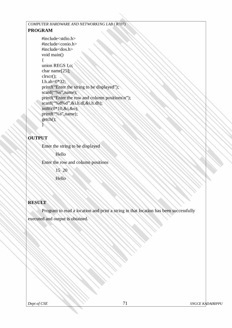
COMPUTER HARDWARE AND NETWORKING LAB ( R707)
Dept of CSE 71 SNGCE KADAIRIPPU
PROGRAM
#include<stdio.h> #include<conio.h> #include<dos.h> void main() { union REGS I,o; char name[25]; clrscr(); I.h.ah=0*32; printf(“Enter the string to be displayed”); scanf(“%s”,name); printf(“Enter the row and column positions\n”); scanf(“%d%d”,&i.h.dl,&i.h.dh); int86(0*10,&i,&o); printf(“%s”,name); getch(); }
OUTPUT
Enter the string to be displayed
Hello
Enter the row and column positions
15 20
Hello
RESULT
Program to read a location and print a string in that location has been successfully
executed and output is obtained.
COMPUTER HARDWARE AND NETWORKING LAB ( R707)
Dept of CSE 72 SNGCE KADAIRIPPU
Ex No:5
CHECK WHETHER THE MOUSE DRIVER IS INSTALLED OR NOT AIM
Write a program to check whether the mouse driver is installed or not.
DESCRIPTION
DOS does not support mouse, provided a mouse and a suitable driver program
that senses the presence of mouse. Programming mouse under DOS involves invoking
interrupts. When invoking an interrupt we also need to pass some parameters which are
simply numbers. These parameters are passed in CPU registers and known as sub functions.
We pass sub-functions to tell which specific functionality of the interrupt we want to use.
Mouse driver is a program that senses the presence of the mouse and
understands signals coming from the mouse port before it translates these signals int relevant
actions. By placing 0 (sub-function) in ax register and invoking mouse interrupt(33H),we can
check whether mouse driver is installed or not. We used int86()
Function to invoke the interrupt.int86() takes 3 arguments: interrupt no and two union REGS
type variables. If mouse driver I not loaded, it returns 0 in ax register.
ALGORITHM
Step 1: Start
Step 2: Declare the variables i,o
Step 3: Initialize the ax register as 0.
Step 4: Call the interrupt int86 with interrupt number 33H.
Step 5: Check the value returned by the interrupt function in ax register in zero or not
5.1 if zero print mouse driver is not loaded
5.2 else output mouse driver is loaded
Step 6: Stop

COMPUTER HARDWARE AND NETWORKING LAB ( R707)
Dept of CSE 73 SNGCE KADAIRIPPU
PROGRAME
/*Check mouse driver loaded or not*/ #include<conio.h> #include<stdio.h> #include<dos.h> void main() { union REGS i,o; clrscr(); i.x.ax=0; int86(0x33,&I,&o); if(o.x.ax==0) printf(“Mouse driver is not loaded”); else printf(“Mouse driver is loaded”); getch(); }
OUTPUT
Mouse driver is loaded
RESULT Program runs successfully and required output is obtained.
COMPUTER HARDWARE AND NETWORKING LAB ( R707)
Dept of CSE 74 SNGCE KADAIRIPPU
Ex No :6
HIDE AND SHOW THE MOUSE POINTER
AIM
Write a program to hide and show the mouse pointer
DESCRIPTION
In this program by placing 0 (sub-function) in ax register and invoking mouse
interrupt(33H),we can check whether the mouse driver is loaded or not. Even if driver is
available, we have no signs of the mouse pointer. To view mouse pointer we have to use sub-
mode, our pointer is a rectangular box. We can observe an arrow if we switch to graphics
mode.
In this program by placing 0 (sub-function) in ax register and invoking mouse
interrupt(33H),we can check whether the mouse driver is loaded or not. Even if driver is
available, we have no signs of the mouse pointer. To view mouse pointer we have to use sub-
mode, our pointer is a rectangular box. We can observe an arrow if we switch to graphics
mode. We use the sub-function 2 and invoke mouse interrupt to hide the mouse pointer. When
writing programs to erase what we draw hence we hide the pointer.
ALGORITHM - Hide mouse pointer
Step 1: Start
Step 2: Declare the variable i,o
Step 3: Initialize the ax register as 0.
Step 4: Call the interrupt interrupt int86 with interrupt number 33H.
Step 5: Check the value returned by the interrupt function in ax register in zero or not
5.1 if zero print mouse driver is not loaded
5.2 else output mouse driver is loaded
5.2.1 Set the input register ax as 01 to show the mouse pointer.
5.2.2 Call the interrupt with interrupt no 33H.
Step 6: Stop

COMPUTER HARDWARE AND NETWORKING LAB ( R707)
Dept of CSE 75 SNGCE KADAIRIPPU
Show mouse pointer
Step 1: Start
Step 2: Declare the variable i,o
Step 3: Initialize the ax register as 0.
Step 4: Call the interrupt int86 with interrupt number 33H.
Step 5: Check the value returned by the interrupt function in ax register in zero or not
5.1 if zero print mouse driver is not loaded
5.2 else output mouse driver is loaded
5.2.1. Set the input register ax as 01 to show the mouse pointer.
5.2.2. Call the interrupt with interrupt no 33H.
5.2.3. Make a delay.
5.2.4. Initialize the output register ax as 02 to hide the mouse pointer.
5.2.5. Call the interrupt with interrupt no 33H.
Step 6: Stop.

COMPUTER HARDWARE AND NETWORKING LAB ( R707)
Dept of CSE 76 SNGCE KADAIRIPPU
PROGRAM
/*show the mouse pointer*/
#include<conio.h> #include<stdio.h> #include<dos.h> #include<process.h> void main() { union REGS i,o; clrscr(); i.x.ax=0; int86(0x33,&I,&o); if(o.x.ax==0) { printf(“Mouse driver is not loaded”); exit(0); } else { printf(“Mouse driver is loaded”); i.x.ax=0x01; int86(0x33,&i,&o); } getch();} /*hide the mouse pointer*/
#include<conio.h> #include<stdio.h> #include<dos.h> #include<process.h> void main() { union REGS i,o; clrscr(); i.x.ax=0; int86(0x33,&I,&o); if(o.x.ax==0) { printf(“Mouse driver is not loaded”); exit(0); } else { printf(“Mouse driver is loaded”); i.x.ax=0x01; int86(0x33,&i,&o); gotoxy(23,24); printf(“\nPress any key:”); getch();

COMPUTER HARDWARE AND NETWORKING LAB ( R707)
Dept of CSE 77 SNGCE KADAIRIPPU
i.x.ax=2; int86(0x33,&i,&o); gotoxy(35,35); printf(“\nMouse pointer is Hidden”); } getch(); }
OUTPUT
Mouse pointer shown.
RESULT
Program runs successfully and required output is obtained.

COMPUTER HARDWARE AND NETWORKING LAB ( R707)
Dept of CSE 78 SNGCE KADAIRIPPU
Ex No:7 GET AND SET THE POSITION OF A MOUSE POINTER
AIM
Write a program to get and set the position of the mouse pointer.
DESCRIPTION
In this program, by placing 0(sub-function) in ax register and invoking mouse
interrupt(33H),we can check whether mouse driver is loaded or not. To view the mouse
pointer, we have to use sub-function 1 in ax register and invoked mouse interrupt to see the
pointer. Since we are in text mode, our pointer is rectangular box. We can observe an arrow if
we switch to graphics mode.
If we need to know the (x,y) co-ordinates of the mouse position we uses the sub-
function 3 and invoked mouse interrupt. Sub-function 3 returns X->co-ordinate in cx register
and Y->co-ordinate in dx register. The program uses a while loop that contiues until a key is
hit and prints x and y co-ordinates. Maximum screen resolution for mouse in text mode is 640
x 200 and in graphics mode is 640x480.
Used register are ax cx and dx. Service no stored in tn ax register x y values
hold by cx and dx respectively. Service no used is 0x00 for driver checking, 0x03 for show
the current position of the mouse pointer and 0x04 used for new location sensing, Interrupt
used is int86() with interrupt no 0x33. For smooth visualization of output delay () function is
use
ALGORITHM
GET THE POSITION
Step 1:Start
Step 2:Declare the variable i,o
Step 3: Initialize the ax register as 0.
Step 4: Call the interrupt int86 with interrupt number 33H.
Step 5: Check the value returned by the interrupt function in ax register is zero or not
5.1 if zero mouse driver is not loaded,exit.
5.2 else output mouse driver is loaded
5.2.1. Set the input register ax as 01 to show the mouse pointer.
5.2.2. Call the interrupt with interrupt no 33H.

COMPUTER HARDWARE AND NETWORKING LAB ( R707)
Dept of CSE 79 SNGCE KADAIRIPPU
5.2.3. Make a delay.
5.2.4. Initialize the output register ax as 02 to hide the mouse pointer.
5.2.5. Call the interrupt with interrupt no 33H.
Step 6: In a while loop until a key is pressed do the following
6.1 Initialize the input register ax as 03 to retrieve the position of the mouse
pointer.
6.2 Call the interrupt with interrupts no 33H.
6.3 Output the position of the mouse pointer in the output registers cx dx.
Step 7: Stop.
SET THE POSITION
Step 1: Start
Step 2: Set initial value of ax 0x00.
Step 3: Call the interrupt int86()with interrupt no 0x33.
Step 4: Check the driver presence if present do the following steps else print driver
absent.
Step 5: Set value of ax is 0x01.
Step 6: call the interrupt int86() with interrupt no 0x33.
Step 7: Set value of ax is 0x03..
Step 8: Call the interrupt int86() with interrupt no 0x33.
Step 9: Show the current position.
Step 10: Set value of ax is 0x04.
Step 11: Enter the new values to the cx and dx registers.
Step 12: Call the interrupt int86() with interrupt no 0x33
Step 13: Stop

COMPUTER HARDWARE AND NETWORKING LAB ( R707)
Dept of CSE 80 SNGCE KADAIRIPPU
PROGRAM
/*get the position of mouse pointer*/
#include<conio.h> #include<stdio.h> #include<dos.h> #include<process.h> void main() { union REGS i,o; clrscr(); i.x.ax=0; int86(0x33,&I,&o); if(o.x.ax==0) { printf(“Mouse driver is not loaded”); exit(0); } else { printf(“Mouse driver is loaded”); i.x.ax=0x01; int86(0x33,&i,&o); gotoxy(5,5); printf(“\nPress any key:”); while(!kbhit()) { i.x.ax=3; int86(0x33,&I,&o); gotoxy(5,5); printf(“x->%d,y->%d”,o.x.cx,o.x.dx); } } getch(); }
/*set the position of the mouse pointer*/
#include<conio.h> #include<stdio.h> #include<dos.h> #include<process.h> void main() { union REGS i,o; int x,y: clrscr(); i.x.ax=0; int86(0x33,&i,&o); if(o.x.ax==0) {

COMPUTER HARDWARE AND NETWORKING LAB ( R707)
Dept of CSE 81 SNGCE KADAIRIPPU
printf(“Mouse driver is not available”); exit(0); } i.x.ax=1; int86(0x33,&i,&o); gotoxy(5,5); i.x.ax=3; int86(0x33,&i,&o); gotoxy(1,1); printf(“x->%d,y->%d”,o.x.cx,o.x.dx); i.x.ax=4; printf(“\nEnter the row and column values:”); scanf(“%d%d”.&x,&y); i.x.cx=x; i.x.dx=y; int86(0x33,&i,&o); i.x.ax=2; int86(0x33,&i,&o); i.x.ax=1; int86(0x33,&i,&o); getch(); }
OUTPUT
x->319,y->99
Enter the row and column values 350 350
Press any key to exit
RESULT
Program run successfully and required output obtained.

COMPUTER HARDWARE AND NETWORKING LAB ( R707)
Dept of CSE 82 SNGCE KADAIRIPPU
Ex No: 8
DISPLAY THE STATUS OF THE MOUSE BUTTONS
AIM
Write a program to display which button of the mouse is pressed
DESCRIPTION
Used register are ax and bx.Service no used is 0x00 for driver checking and 0x03 for
show the mouse pointer current location. Interrupt used is int86() with interrupt no 0x33. For
smooth visualization of output delay() function is used.
ALGORITHM
Step 1: Start
Step 2: Set initial value of ax 0x00.
Step 3: Call the interrupt int86()with interrupt no 0x33.
Step 4: Check the driver presence if present do the following steps else print driver
absent
Step 5: Go to specified screen position.
Step 6: Wait for a key press.
Step 7:While not a keyboard hit then do till step 7.11 until a key pressed.
7.1: Set value of ax register 0x03
7.2: Call the interrupt int86() with interrupt no 0x33.
7.3: do AND operation with content of bx and 07H save the result to x
7.4: Compare the value of x with various possibilities.
7.1: Case 1 print left button pressed.
7.5: Case 2 print right button pressed.
7.6: Case 3 print left and right button pressed.
7.7: Case 4 print middle button pressed.
7.8: Case 5 print left and middle button pressed.
7.9: Case 6 print right and middle button pressed.
7.10: Case 7 print all the three button pressed.
7.11: Default print no button pressed.
Step 8: Stop.

COMPUTER HARDWARE AND NETWORKING LAB ( R707)
Dept of CSE 83 SNGCE KADAIRIPPU
PROGRAME
#include<conio.h> #include<stdio.h> #include<dos.h> #include<process.h> void main() { union REGS i,o; int x,y: clrscr(); i.x.ax=0; int86(0x33,&i,&o); if(o.x.ax==0) { printf(“Mouse driver is not available”); exit(0); } i.x.ax=1; int86(0x33,&i,&o); gotoxy(23,24); printf(“Press any key”); while(!khbit()) { delay(500); i.x.ax=3; int86(0x33,&i,&o); x=o.x.bx &7; clrscr(); switch(x) { case 1: printf(“Left mouse button is pressed”); break; case 2: printf(“Right mouse button is pressed”); break; case 3: printf(“Left & Right mouse button are pressed”); break; case 4: printf(“Middle button is pressed”); break; case 5: printf(“Left & Middle button are pressed”); break; case 6: printf(“Right & Middle mouse button are pressed”); break; case 7: printf(“All the three mouse button are pressed”); break; default: printf(“No button is pressed”);
} }
getch();
}
COMPUTER HARDWARE AND NETWORKING LAB ( R707)
Dept of CSE 84 SNGCE KADAIRIPPU
RESULT
Program runs successfully and required output is obtained.

COMPUTER HARDWARE AND NETWORKING LAB ( R707)
Dept of CSE 85 SNGCE KADAIRIPPU
Ex No: 9 INITIALIZE SERIAL PORT FOR COMMUNICATION AIM
Write a program to initialize serial port
DESCRIPTION
Serial port is a connection or interface on the computer used to connect a serial
device to the computer. In serial port communication, the read data is written to the port.
int86 is a software interrupt interface which executes an 8086 software interrupt by argument
interrupt numbers set ah with 0x00 and 0x00. Thus call the interrupt 86 with argument 0x1
and set the value that o.h.ah and mask. Then select the status according to the value of r and
mask.
ALGORITHM Step1: Start. Step 2: Declare r and initialize mask as1. Step 3: set i.h.ah=0x00, i.h.al=0x05,i.x.dx=0x00. Step 4: call int86 with argument 0x04 Step 5: while(mask<=128) 5.1: 1r=(o.h.ah)&mask. 5.2: switch(r) Case 128: print “time out” Case 64: print “shift register empty” Case 32: print “hold register empty” Case 16: print “break detected” Case 8: print “Framing error” Case 4: print “parity error”Case 64: Case 2: print “Overrun Error” Case 1: print “Data Valid” 5.3: mask=mask82 Step 6: Stop.
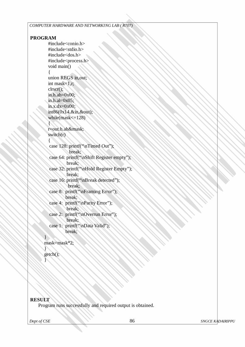
COMPUTER HARDWARE AND NETWORKING LAB ( R707)
Dept of CSE 86 SNGCE KADAIRIPPU
PROGRAM
#include<conio.h> #include<stdio.h> #include<dos.h> #include<process.h> void main() { union REGS in,out; int mask=1,r; clrscr(); in.h.ah=0x00; in.h.al=0x05; in.x.dx=0x00; int86(0x14,&in,&out); while(mask<=128) { r=out.h.ah&mask; switch(r) { case 128: printf(“\nTimed Out”); break; case 64: printf(“\nShift Register empty”); break; case 32: printf(“\nHold Register Empty”); break; case 16: printf(“\nBreak detected”); break; case 8: printf(“\nFraming Error”); break; case 4: printf(“\nParity Error”); break; case 2: printf(“\nOverrun Error”); break; case 1: printf(“\nData Valid”); break; } mask=mask*2; } getch(); }
RESULT
Program runs successfully and required output is obtained.

COMPUTER HARDWARE AND NETWORKING LAB ( R707)
Dept of CSE 87 SNGCE KADAIRIPPU
Ex No: 10 READ THE PARTITION TABLE OF A HARD DISK
AIM
Write a program for partition table of a hard disk.
DESCRIPTION
The term hard is used to distinguish it from a soft, or floppy, disk. Hard disks hold more
data and are aster than floppy disks. Function used to retrieve the partition table is bios disk.
The very first sector of hard disk contains the master boot record. After executing bios disk if
the function returns 0 then reading is success. A structure is used to hold the partition table
values.
ALGORITHM
Step 1: Start
Step 2: Create a structure say partition to hold the values
Step 3: Create another structure details.
Step 4: Call biosdisk function.
Step 5: If return is zero then error in reading else reading successful.
Step 6: Print the values in the structures.
Step 7: Stop.

COMPUTER HARDWARE AND NETWORKING LAB ( R707)
Dept of CSE 88 SNGCE KADAIRIPPU
PROGRAM
#include<stdio.h> #include<alloc.h> #include<conio.h> #include<bios.h> struct partition { char boot_code[0x1be]; unsigned char bootflag; unsigned char begin_hdnum; unsigned int begin_seccy1: unsigned char sys_code; unsigned char end_seccy1; unsigned int end_seccy1; long br_secnum; unsigned long total_sectors; }part[4]; struct details { struct partition part[4]; int sign; }buffer; main() { int i; char temp; clrscr(); if(biosdisk(_DISK_READ,0x80,0,0,1,1,&buffer)==0) { for(i=0;i<4;i++) { printf(“\nPARTITION TABLE%d ENTRY:\n,i+1); if(buffer.part[i].bootflag!=0) printf(“\n BOOT Flag:Active”); else printf(“\n BOOT Flag Inactive”); printf(“Begins HEAD Number:%x”,buffer.part[i].begin_hdnum); printf(“\n Begins Sector and Cylinder:%x”,buffer.part[i].begin_seccy1); printf(“\n System Code”); switch(buffer.part[i].sys_code) { case 0: printf(“unknwn”); break; case 1: printf(“DOS 12-bit FAT”); break;

COMPUTER HARDWARE AND NETWORKING LAB ( R707)
Dept of CSE 89 SNGCE KADAIRIPPU
case 4: printf(“DOS 16-bit FAT”); break: default:printf(“EXTENDED DOS partition”); break; } printf(“\n END Head Number:%x”,buffer.part[i].begin_hdnum); printf(“\n Sector and Cylinder of last sector:%x”,buffer.part[i].begin_seccy1); printf(“\n Beginning relative sector Number:%x”, buffer.part[i].br_secnum); printf(“\n Total Sectors:%ld”,buffer.part[i].total_sectors); getch(); } } else { printf(“\n SOME Error in Reading the partition table”); getch(); } return 0; }
RESULT
Program runs successfully and required output is obtained.

COMPUTER HARDWARE AND NETWORKING LAB ( R707)
Dept of CSE 90 SNGCE KADAIRIPPU
NO:11 TOGGLE KEYS
AIM:
To write a program to read the status of CAPS,NUM and SCROLL locks on
akeybord and toggle it.
DESCRIPTION
The toggling of the keybord is between 2 modes.The most common is the
CAPS lock key which causes all letters to appear as capitalswhen it is activated. Other
common toggle keys include Numlock that alternates between the numeric keypad used for
numeric entry and using it for cursor movement and scroll lock which is used to stop a
sceerful of information from scrolling past ,which is not a common problem with modern
interfaces.The bits of the byte on the location 0x417 keep track of the toggle key ,whereas the
bytes in the location 0x418 monitor whether these keys are pressed or not.
ALGORITHM
1. Start 2. Initialize a pointer that points to location 417h
3. Read the status of CAPS,NUM and SCROLL LOCK. 4. Toggle the status
5. End.
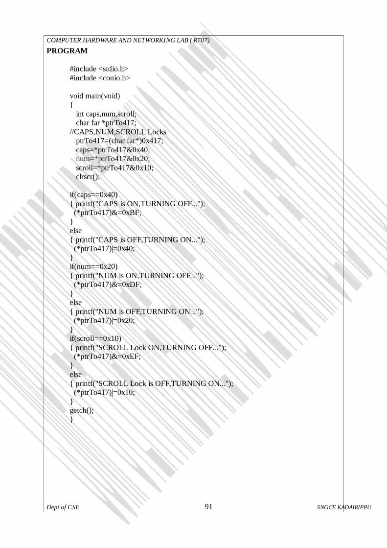
COMPUTER HARDWARE AND NETWORKING LAB ( R707)
Dept of CSE 91 SNGCE KADAIRIPPU
PROGRAM
#include <stdio.h> #include <conio.h> void main(void) { int caps,num,scroll; char far *ptrTo417; //CAPS,NUM,SCROLL Locks ptrTo417=(char far*)0x417; caps=*ptrTo417&0x40; num=*ptrTo417&0x20; scroll=*ptrTo417&0x10; clrscr(); if(caps==0x40) { printf("CAPS is ON,TURNING OFF..."); (*ptrTo417)&=0xBF; } else { printf("CAPS is OFF,TURNING ON..."); (*ptrTo417)|=0x40; } if(num==0x20) { printf("NUM is ON,TURNING OFF..."); (*ptrTo417)&=0xDF; } else { printf("NUM is OFF,TURNING ON..."); (*ptrTo417)|=0x20; } if(scroll==0x10) { printf("SCROLL Lock ON,TURNING OFF..."); (*ptrTo417)&=0xEF; } else { printf("SCROLL Lock is OFF,TURNING ON..."); (*ptrTo417)|=0x10; } getch(); }

COMPUTER HARDWARE AND NETWORKING LAB ( R707)
Dept of CSE 92 SNGCE KADAIRIPPU
TESTING STRATEGY
CASE 1: CAPS:OFF NUM: ON SCROLL:ON
CASE 2: CAPS:ON NUM:OFF SCROLL:ON
CASE 3: CAPS:ON NUM:ON SCROLL:OFF
SUMMARY OF RESULTS
CASE1 : Caps lock is OFF,turning ON Num lock is on,turning off
scroll lock is on, turning off CASE2 : Caps lock is On,turning OFF
Num lock is OFF,turning ON scroll lock is on, turning off
CASE3 : Caps lock is ON,turning OFF Num lock is on,turning off
scroll lock is OFF, turning ON RESULT
Program runs successfully and required output is obtained.

COMPUTER HARDWARE AND NETWORKING LAB ( R707)
Dept of CSE 93 SNGCE KADAIRIPPU
Cycle 3