FALSE CLAIMS ACT COMPLAINT “QUI TAM”dig.abclocal.go.com/kgo/PDF/Harman_whistleblower.pdfThe...
130
1 IN THE UNITED STATES DISTRICT COURT FOR THE EASTERN DISTRICT OF TEXAS MARSHALL DIVISION JOSHUA HARMAN, on behalf of § The UNITED STATES OF AMERICA, § § PLAINTIFF/Relator, § CIVIL ACTION NO. ____________ § V. § FILED UNDER SEAL § 31 U.S.C. §§ 3729-32 TRINITY INDUSTRIES, INC, § JURY TRIAL DEMANDED § DEFENDANT § FALSE CLAIMS ACT COMPLAINT “QUI TAM” TO THE HONORABLE JUDGE OF SAID COURT: The United States of America, by and through qui tam Relator, Joshua Harman, brings this action under 31 U.S.C. §§ 3729-32 (The “False Claims Act”) to recover from Trinity Industries, Inc. (“Trinity”) for all damages, penalties, and other remedies available under the False Claims Act on behalf of the United States and himself and would show unto the Court the following: PARTIES 1. Relator, Joshua Harman (“Harman”), is an individual and citizen of the United States of America residing in Swords Creek, Virginia. 2. Defendant Trinity Industries, Inc. is a Delaware corporation authorized to do business in Texas with its principal place of business located at 2525 Stemmons Freeway, Dallas, Texas 75207. Trinity’s Texas agent for service of process is CT Corp System, 350 N. St. Paul St., Suite 2900, Dallas, Texas 75201-4234. Case 2:12-cv-00089-JRG Document 1 Filed 03/06/12 Page 1 of 10 PageID #: 1
Transcript of FALSE CLAIMS ACT COMPLAINT “QUI TAM”dig.abclocal.go.com/kgo/PDF/Harman_whistleblower.pdfThe...
1
IN THE UNITED STATES DISTRICT COURT
FOR THE EASTERN DISTRICT OF TEXAS
MARSHALL DIVISION
JOSHUA HARMAN, on behalf of §
The UNITED STATES OF AMERICA, §
§
PLAINTIFF/Relator, § CIVIL ACTION NO. ____________
§
V. § FILED UNDER SEAL
§ 31 U.S.C. §§ 3729-32
TRINITY INDUSTRIES, INC, § JURY TRIAL DEMANDED
§
DEFENDANT §
FALSE CLAIMS ACT COMPLAINT
“QUI TAM”
TO THE HONORABLE JUDGE OF SAID COURT:
The United States of America, by and through qui tam Relator, Joshua Harman, brings
this action under 31 U.S.C. §§ 3729-32 (The “False Claims Act”) to recover from Trinity
Industries, Inc. (“Trinity”) for all damages, penalties, and other remedies available under the
False Claims Act on behalf of the United States and himself and would show unto the Court the
following:
PARTIES
1. Relator, Joshua Harman (“Harman”), is an individual and citizen of the United States of
America residing in Swords Creek, Virginia.
2. Defendant Trinity Industries, Inc. is a Delaware corporation authorized to do business in
Texas with its principal place of business located at 2525 Stemmons Freeway, Dallas, Texas
75207. Trinity’s Texas agent for service of process is CT Corp System, 350 N. St. Paul St., Suite
2900, Dallas, Texas 75201-4234.
Case 2:12-cv-00089-JRG Document 1 Filed 03/06/12 Page 1 of 10 PageID #: 1
2
JURISDICTION AND VENUE
3. This Court maintains subject matter jurisdiction over this action pursuant to 31 U.S.C.
§3732(a) (False Claims Act) and 28 U.S.C. § 1331 (Federal Question).
4. Venue is proper in this Court under 31 U.S.C. § 3732(a) because Trinity manufactures
and sells guardrail systems throughout the Eastern District of Texas as well as throughout the
United States.
5. Harman is the original source of and has direct and independent knowledge of all
publicly disclosed information that the allegations herein are based upon. Harman has personally
gathered all the documentation and photographs substantiating the allegations herein.
Additionally, he has voluntarily provided all such information to the Government prior to the
filing of this action.
FACTS
6. Trinity is in the business of manufacturing various highway safety and construction
products for use across the United States. In particular, Trinity manufactures the ET-Plus
guardrail end terminal (“ET-Plus”) under an exclusive license agreement from Texas A & M
University.1 The ET-Plus is commonly referred to as a “head” and when used in conjunction
with the standard “W” style guardrail seen throughout the roads and highways of America is
designed to absorb and dissipate the energy of a vehicular impact. Upon impact the guardrail is
extruded through the head and flattened out into a ribbon, thus absorbing the majority of the
collision energy. The following picture illustrates an early model ET-Plus performing correctly:
1 See http://highwayguardrail.com/products/etplus.html
Case 2:12-cv-00089-JRG Document 1 Filed 03/06/12 Page 2 of 10 PageID #: 2

3
7. The ET-Plus is actually a modified version of what was originally designed and marketed
as the ET-2000. See Exhibit A (Presentation which includes history of the ET modifications).
This newly redesigned head being approximately 100 pounds lighter than the ET-2000 was
submitted to the Federal Government and approved for use in January of 2000. The original
production of the ET-Plus, built to the approved specifications, was overall very successful. Not
only did it work for an initial impact, it continued to work if struck again in a separate incident
but before maintenance crews were able to repair it. Shown below is a top view drawing of the
head itself:
Case 2:12-cv-00089-JRG Document 1 Filed 03/06/12 Page 3 of 10 PageID #: 3

4
8. The ET-Plus, along with each and every other product used on the National Highway
System, must undergo rigorous testing to determine and validate crashworthiness before the
product may be placed on the National Highway System. The Federal Highway Administration,
a division of government under the U.S. Department of Transportation, along with other state
and federal organizations, are charged with establishing the crashworthiness criteria for products
such as the ET-Plus. Once a product is approved for use along the National Highway System its
design specifications cannot be altered. If altered, the product must undergo additional testing
and approval prior to placement on the National Highway System.
9. Beginning in early 2005, a different ET-Plus started appearing along the National
Highway System. In particular, this head was manufactured with a four inch feeder chute and a
shorter overall height.
In addition, due to the shortened height, the feeder rails are actually inserted into the head .75
Case 2:12-cv-00089-JRG Document 1 Filed 03/06/12 Page 4 of 10 PageID #: 4

5
inches rather than being welded flush to it. This drastically reduced the overall space of the
feeder chute.
10. Trinity twice petitioned the FHWA for modifications to other components of the overall
ET-Plus system, once in September of 2005 and then again in August of 2007. See Exhibit B
(CC-94 and CC94a). These modifications, however, primarily dealt with the breakaway post
system that upholds the guardrail near the ET-Plus head. Nowhere in these design changes does
Trinity mention the reduced feeder chute size changes. In fact, to date Harman has been unable
to locate any documentary proof that Trinity ever officially petitioned the Government for
approval to the feeder chute changes outlined above. The reason is simple, the documentation
does not exist. As explained more fully in ¶ 14 below, Trinity failed to submit the modifications
for approval.
11. The problem with the ET-Plus as modified in 2005 is that the guardrail does not feed
properly through the chute due to the reduced area of the feeder chute itself. This causes the
guardrail to “throat lock” in the head during impact. Once throat locked, the energy of the crash
is diverted elsewhere usually causing the guardrail to double over on itself or protrude through
the crashing vehicle. If the guardrail and head assembly protrude like a spear through the
vehicle, the inevitable result is usually death or serious bodily injury to the persons in the
vehicle. The following pictures illustrate the front and back of a vehicle striking a guardrail after
it had been hit previously but before maintenance crews could repair the head and rail:
Case 2:12-cv-00089-JRG Document 1 Filed 03/06/12 Page 5 of 10 PageID #: 5

6
On the other hand, if the guardrail doubles over on itself after throat lock, it creates a new hazard
for other approaching vehicles that may encounter the head before a maintenance crew can repair
it. A doubled over guardrail after throat lock is shown below:
12. It is believed that there literally hundreds of thousands of these defective heads on the
National Highway System as well as state and local roadways. The potential for danger is
obvious and inevitable. Harman is personally aware of fatalities involving the modified ET-Plus
in Tennessee, Virginia, Kentucky, and possibly Texas. In over 100 accidents involving the
modified ET-Plus, Harman has not seen the head function properly.
13. The only logical conclusion as to why Trinity would modify the ET-Plus is to save
manufacturing costs. It is believed that the 4” inch C channel used to construct the feeder chute
is substantially cheaper than 5” inch C channel. Trinity, by and through local highway
Case 2:12-cv-00089-JRG Document 1 Filed 03/06/12 Page 6 of 10 PageID #: 6
7
contractors and the individual States implementing federally funded highway projects, literally
made millions in revenue off of this defective product at the expense of the United States
Government and the American taxpayer. Improvements made to the National Highway System
are typically made by the individual States that bid out and pay for the projects and then seek
reimbursement from the federal government. Individual highway contractors would bid on
projects that contained quotes for material supplied by Trinity that was alleged to conform to the
federal standards for crashworthiness. Once awarded the contract, the highway contractor would
purchase the defective ET-Plus head from Trinity and install it along the specified roadway. In
the end, federal dollars were and continue to be paid to Trinity to purchase the faulty ET-Plus
heads based on Trinity’s false statements and conduct. This constitutes a false claim under the
FCA. See U.S. v. Mackby, 339 F.3d 1013, 1018 (9th
Cir. 2003), cert. denied, 541 U.S. 936
(2004).
14. Harman has made a conscious effort to bring awareness to this issue. Specifically, over
the past month Harman has had numerous contacts with Mr. Nick Artimovich, II regarding the
complaints made against Defendant herein. Mr. Artimovich is a highway engineer for the
Federal Highway Administration, Office of Safety Technologies.2 Additionally, he is the
program director for crashworthiness testing of roadside hardware used on the National Highway
System. Mr. Artimovich admitted to Harman that the ET-Plus as modified has never been
officially submitted or approved for use on the National Highway System by the FHWA. Lastly,
2 Nicholas Artimovich, II, Highway Engineer, Office of Safety Technologies, Federal Highway
Administration HSST, 1200 New Jersey Avenue SE, Room E71-322, Washington, DC 20590.
email: [email protected], phone: 202-366-1331, fax: 202-366-3222, web:
http://safety.fhwa.dot.gov
Case 2:12-cv-00089-JRG Document 1 Filed 03/06/12 Page 7 of 10 PageID #: 7
8
as recently as three weeks ago at the American Traffic Safety Services Association3 annual Expo
in Florida, Harman provided a summary presentation of the facts herein to the following state
highway officials: New Hampshire DOT, CalTrans, Florida DOT, Oklahoma DOT, North
Carolina DOT, Pennsylvania DOT, and Mississippi DOT.
15. Harman is also the owner and author of a website entitled www.failingheads.com which
contains most of the information found in this complaint. This website explains the history of
the ET head product line and the current failures that are being seen every day. The website just
came on live in late January of 2012 and has restricted access. Harman is also the owner and
author of a website entitled www.make-a-way.phrop.com which contains over 5000 photographs
of accidents involving the modified ET-Plus throughout the United States.
CAUSE OF ACTION
Violations of the False Claims Act
16. Harman incorporates and re-alleges all of the foregoing allegations herein.
17. Based upon the acts described above, Defendant knowingly violated on or more of the
following:
a. Knowingly presented, or caused to be presented, a false or fraudulent claim for
payment or approval;
b. Knowingly made, used, or caused to be made or used, a false record or statement
to get a false or fraudulent claim paid or approved by the Government.
18. The United States, unaware of the falsity of these claims, records, and statements made
by the Defendant, and in reliance on the accuracy thereof, paid money to Defendant and/or
3 ATSSA is a highway product industry trade group. See www.atssa.com.
Case 2:12-cv-00089-JRG Document 1 Filed 03/06/12 Page 8 of 10 PageID #: 8

9
various highway contractors for the fraudulent claims. These payments were most likely made
to the various States under the Federal Aid Highway Program.4
19. The United States and the general public have been damaged as a result of Defendant’s
violations of the False Claims Act.
PRAYER
20. For the reasons set forth above, Harman, on behalf of the United States, respectfully
requests this Court to find that Defendant has damaged the United States Government as a result
of its conduct under the False Claims Act. Harman prays that judgment enter against Defendant
for all applicable damages, including but not limited to the following:
a. Actual damages in an amount sufficient to cover the cost to recall and replace
every defective guardrail product of Defendant placed on the public roadways of
the United States.
b. Civil Penalties in an amount of three times the actual damages suffered by the
Government.
c. Relator seeks a fair and reasonable amount of any award for his contribution to
the Government’s investigation and recovery pursuant to 31 U.S.C. §§ 3730(b)
and (d) of the False Claims Act.
d. Attorney’s fees and costs awarded to Relator.
e. Pre-judgment and post judgment interest.
f. All other relief on behalf of the Relator and/or United States Government to
which they may be entitled at law or equity.
4 http://www.fhwa.dot.gov/reports/financingfederalaid/limit.htm
Case 2:12-cv-00089-JRG Document 1 Filed 03/06/12 Page 9 of 10 PageID #: 9

10
Respectfully Submitted,
By:______/s/ JBM_____________
Josh B. Maness
Texas Bar No. 24046340
P.O. Box 1785
Marshall, Texas 75671
Tel. (903) 407-8455
Fax. (877)320-5751
Attorney for Relator
CERTIFICATE OF SERVICE
I, Josh Maness, certify that a true and correct copy of the foregoing has been served on
counsel for all parties via the Court’s CM/ECF system this the 6th
day of March 2012.
Additionally, the following parties were served via CMRRR:
Hon. Eric Holder
Attorney General of the United States
U.S. Dept. of Justice
950 Pennsylvania Avenue NW
Washington, DC 20530-0001
Hon. Jim Middleton and/or Hon. Randi Rusell
AUSA for the Eastern Dist. of Texas
110 N. College, Suite 700
Tyler, Texas 75702
Hon. Randy Ramseyer
AUSA for the Western Dist. of Virginia
180 W. Main Street
Abingdon, Virginia 24210
______/s/ JBM_____________
Josh B. Maness
Case 2:12-cv-00089-JRG Document 1 Filed 03/06/12 Page 10 of 10 PageID #: 10

SPIG ET-2000 and ET-Plus are
trademarks of Trinity Industries
Failure Assessment Of
Guardrail Extruder Terminals
January 14, 2012
Case 2:12-cv-00089-JRG Document 1-1 Filed 03/06/12 Page 1 of 109 PageID #: 11
SPIG ET-2000 and ET-Plus are
trademarks of Trinity Industries
Failure Assessment Of
Guardrail Extruder Terminals
January 14, 2012
This presentation is the sole opinion of SPIG
Industries based on an empirical analysis of
guardrail terminal impacts throughout a number
of states.
Case 2:12-cv-00089-JRG Document 1-1 Filed 03/06/12 Page 2 of 109 PageID #: 12

SPIG ET-2000 and ET-Plus are
trademarks of Trinity Industries
ET-Plus Background
The ET-2000 is the first extruding type guardrail end
terminal and was accepted by FHWA in August 1995.
Case 2:12-cv-00089-JRG Document 1-1 Filed 03/06/12 Page 3 of 109 PageID #: 13

SPIG ET-2000 and ET-Plus are
trademarks of Trinity Industries
ET-Plus Background
The ET-2000 is the first extruding type guardrail end
terminal and was accepted by FHWA in August 1995.
Case 2:12-cv-00089-JRG Document 1-1 Filed 03/06/12 Page 4 of 109 PageID #: 14

SPIG ET-2000 and ET-Plus are
trademarks of Trinity Industries
ET-Plus Background
The ET-2000 is the first extruding type guardrail end
terminal and was accepted by FHWA in August 1995.
Case 2:12-cv-00089-JRG Document 1-1 Filed 03/06/12 Page 5 of 109 PageID #: 15

SPIG ET-2000 and ET-Plus are
trademarks of Trinity Industries
ET-Plus Background
The early production model ET-PLUS was a redesign based
on the ET-2000 that eliminated 93 pounds of weight and
reduced the number of parts.
Case 2:12-cv-00089-JRG Document 1-1 Filed 03/06/12 Page 6 of 109 PageID #: 16
SPIG ET-2000 and ET-Plus are
trademarks of Trinity Industries
ET-Plus Background
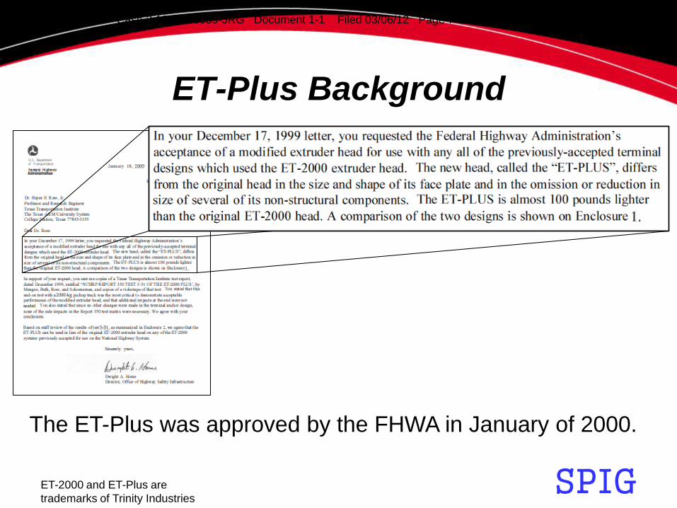
The ET-Plus was approved by the FHWA in January of 2000.
Case 2:12-cv-00089-JRG Document 1-1 Filed 03/06/12 Page 7 of 109 PageID #: 17

SPIG ET-2000 and ET-Plus are
trademarks of Trinity Industries
ET-Plus Background
The early production model of ET-Plus was produced from
about 1999 to 2005 and had a change in the post breaker
shape from square to triangular sometime in 2001.
Case 2:12-cv-00089-JRG Document 1-1 Filed 03/06/12 Page 8 of 109 PageID #: 18

SPIG ET-2000 and ET-Plus are
trademarks of Trinity Industries
ET-Plus Background
The early production model of ET-Plus was produced from
about 1999 to 2005 and had a change in the post breaker
shape from square to triangular sometime in 2001.
Case 2:12-cv-00089-JRG Document 1-1 Filed 03/06/12 Page 9 of 109 PageID #: 19

SPIG ET-2000 and ET-Plus are
trademarks of Trinity Industries
ET-Plus Background
The top drawing is a
plan view of an early
production ET-Plus
with a square post
breaker.
The bottom drawing is
a side view of the
same early production
ET-Plus.
PLAN
SIDE
POST BREAKER
Case 2:12-cv-00089-JRG Document 1-1 Filed 03/06/12 Page 10 of 109 PageID #: 20

SPIG ET-2000 and ET-Plus are
trademarks of Trinity Industries
ET-Plus Background
The top drawing is a
plan view of an early
production ET-Plus
with a triangular
post breaker.
The bottom drawing
is a side view of the
same ET-Plus.
PLAN
SIDE
POST BREAKER
Case 2:12-cv-00089-JRG Document 1-1 Filed 03/06/12 Page 11 of 109 PageID #: 21
SPIG ET-2000 and ET-Plus are
trademarks of Trinity Industries
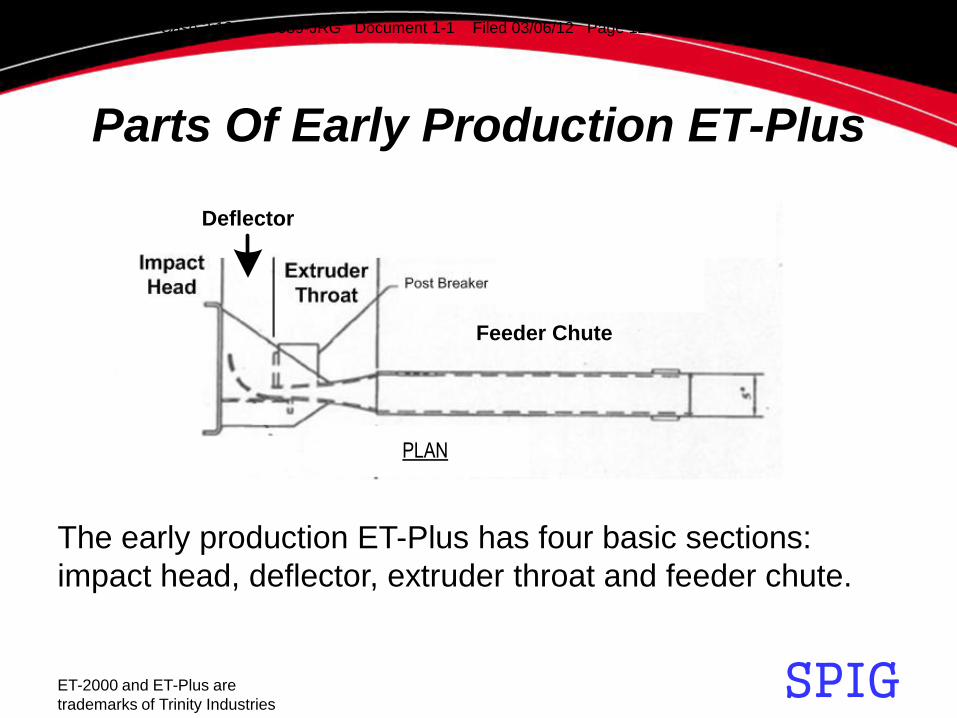
Parts Of Early Production ET-Plus
The early production ET-Plus has four basic sections:
impact head, deflector, extruder throat and feeder chute.
Deflector
Feeder Chute
PLAN
Case 2:12-cv-00089-JRG Document 1-1 Filed 03/06/12 Page 12 of 109 PageID #: 22

SPIG ET-2000 and ET-Plus are
trademarks of Trinity Industries
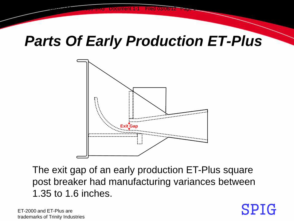
The end of the extruder throat has an exit gap.
Deflector
Feeder Chute
Parts Of Early Production ET-Plus
Case 2:12-cv-00089-JRG Document 1-1 Filed 03/06/12 Page 13 of 109 PageID #: 23
SPIG ET-2000 and ET-Plus are
trademarks of Trinity Industries
The exit gap of an early production ET-Plus square
post breaker had manufacturing variances between
1.35 to 1.6 inches.
Exit Gap
Parts Of Early Production ET-Plus
Case 2:12-cv-00089-JRG Document 1-1 Filed 03/06/12 Page 14 of 109 PageID #: 24

SPIG ET-2000 and ET-Plus are
trademarks of Trinity Industries
The exit gap of an early production ET-Plus triangle
post breaker had manufacturing variances between
1.1 to 1.5 inches.
Exit Gap
Parts Of Early Production ET-Plus
Case 2:12-cv-00089-JRG Document 1-1 Filed 03/06/12 Page 15 of 109 PageID #: 25

SPIG ET-2000 and ET-Plus are
trademarks of Trinity Industries
This is a side view of the ET-Plus showing the top feeder rail
and the bottom feeder rail of the feeder chute.
Bottom Feeder Rail
Top Feeder Rail
Parts Of Early Production ET-Plus
Case 2:12-cv-00089-JRG Document 1-1 Filed 03/06/12 Page 16 of 109 PageID #: 26

SPIG ET-2000 and ET-Plus are
trademarks of Trinity Industries
This is a plan view of an early production ET-Plus showing
the feeder chute had a width of 5 inches and a length of 37
inches with either the triangular post breaker or the square
post breaker.
5 [127]
37 [940]
Parts Of Early Production ET-Plus
Case 2:12-cv-00089-JRG Document 1-1 Filed 03/06/12 Page 17 of 109 PageID #: 27
SPIG ET-2000 and ET-Plus are
trademarks of Trinity Industries
Early Production ET-Plus
Performance
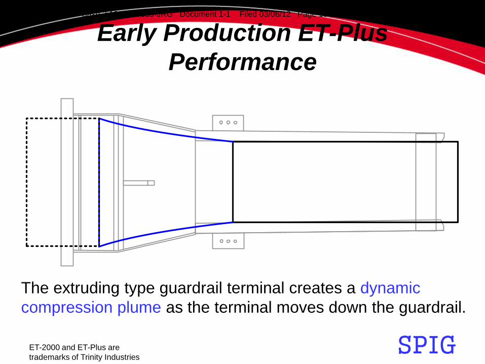
The extruding type guardrail terminal creates a dynamic
compression plume as the terminal moves down the guardrail.
Case 2:12-cv-00089-JRG Document 1-1 Filed 03/06/12 Page 18 of 109 PageID #: 28

SPIG ET-2000 and ET-Plus are
trademarks of Trinity Industries
Early Production ET-Plus
Performance
12
3
The extruding type guardrail terminal 1) plumes the guardrail, 2)
flattens the guardrail, and then 3) deflects the flattened
guardrail.
Case 2:12-cv-00089-JRG Document 1-1 Filed 03/06/12 Page 19 of 109 PageID #: 29

SPIG ET-2000 and ET-Plus are
trademarks of Trinity Industries
Early Production ET-Plus
Performance
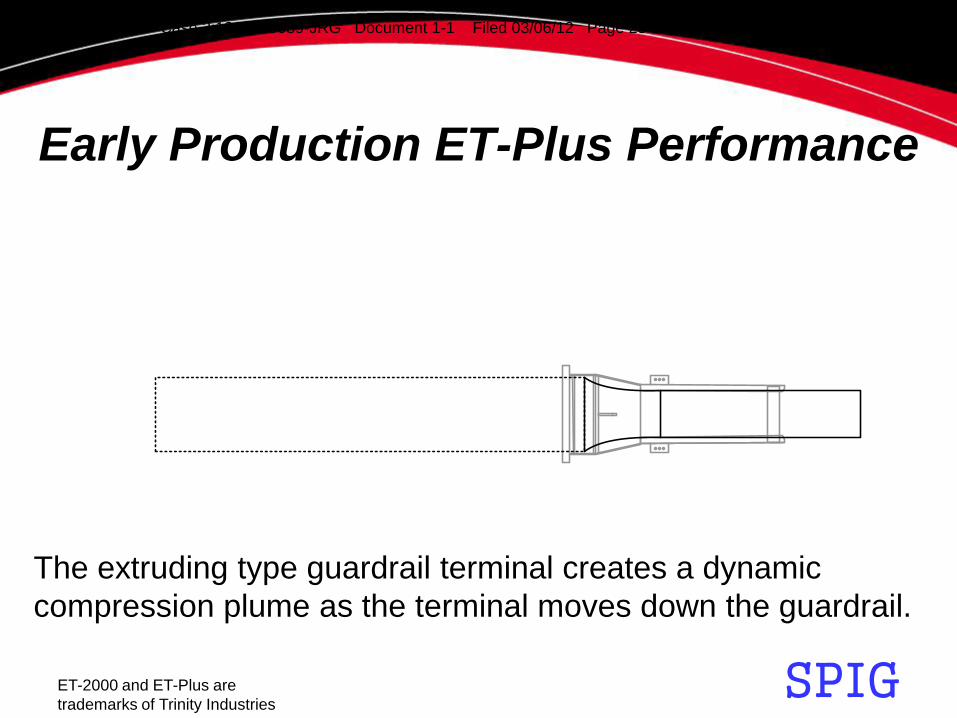
The extruding type guardrail terminal creates a dynamic
compression plume as the terminal moves down the guardrail.
Case 2:12-cv-00089-JRG Document 1-1 Filed 03/06/12 Page 20 of 109 PageID #: 30

SPIG ET-2000 and ET-Plus are
trademarks of Trinity Industries
Early Production ET-Plus Performance
The extruding type guardrail terminal creates a dynamic
compression plume as the terminal moves down the guardrail.
Case 2:12-cv-00089-JRG Document 1-1 Filed 03/06/12 Page 21 of 109 PageID #: 31

SPIG ET-2000 and ET-Plus are
trademarks of Trinity Industries
Early Production ET-Plus Performance
The extruding type guardrail terminal creates a dynamic
compression plume as the terminal moves down the guardrail.
Case 2:12-cv-00089-JRG Document 1-1 Filed 03/06/12 Page 22 of 109 PageID #: 32
SPIG ET-2000 and ET-Plus are
trademarks of Trinity Industries
Early Production ET-Plus Performance
The extruding type guardrail terminal creates a dynamic
compression plume as the terminal moves down the guardrail.
Case 2:12-cv-00089-JRG Document 1-1 Filed 03/06/12 Page 23 of 109 PageID #: 33

SPIG ET-2000 and ET-Plus are
trademarks of Trinity Industries
Early Production ET-Plus
Performance
The guardrail is compressed by horizontal forces from
the extruder throat and subsequently flattened by the
deflector into a ribbon.
Force
ForcePLAN
Case 2:12-cv-00089-JRG Document 1-1 Filed 03/06/12 Page 24 of 109 PageID #: 34

SPIG ET-2000 and ET-Plus are
trademarks of Trinity Industries
Early Production ET-Plus
Performance
Most of the horizontal compressing forces are adjacent
to the exit gap of the extruder throat that create the
dynamic compression plume.
Force
ForcePLAN
Case 2:12-cv-00089-JRG Document 1-1 Filed 03/06/12 Page 25 of 109 PageID #: 35

SPIG ET-2000 and ET-Plus are
trademarks of Trinity Industries
Early Production ET-Plus
Performance
UNALTERED W-BEAM
DYNAMIC
COMPRESSION
PLUME
FLATTENED
GUARDRAIL
(RIBBON)
FLAT LINE
CHANGE LINE
The dynamic compression plume is located between
the change line and the flat line as the terminal moves
along the guardrail during an impact.
Case 2:12-cv-00089-JRG Document 1-1 Filed 03/06/12 Page 26 of 109 PageID #: 36
SPIG ET-2000 and ET-Plus are
trademarks of Trinity Industries
Early Production ET-Plus
Performance
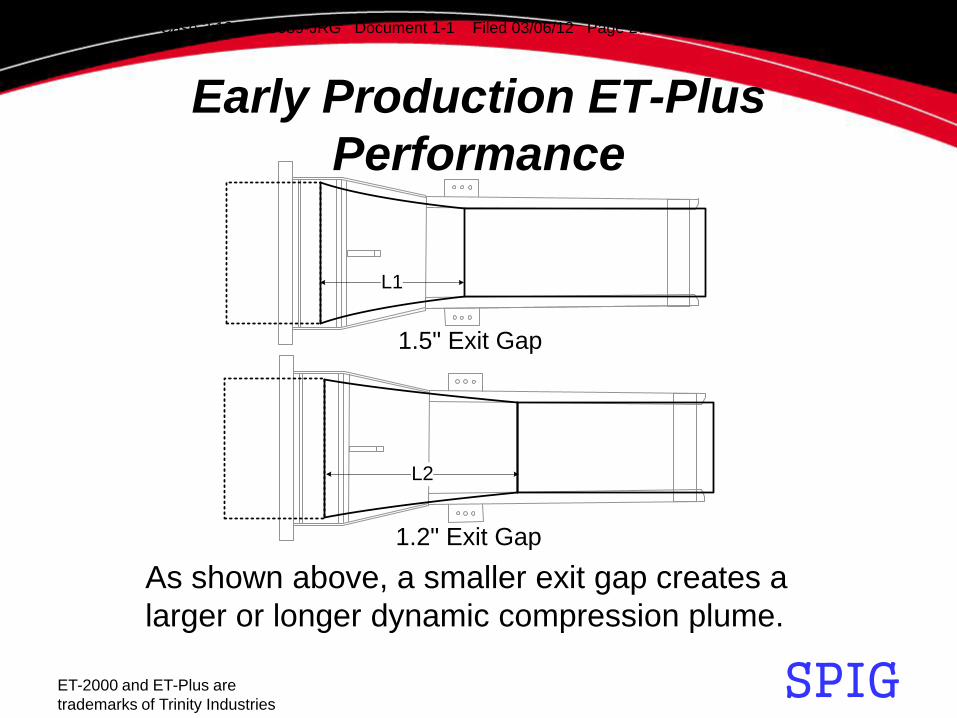
1.5" Exit Gap
L1
L2
1.2" Exit Gap
As shown above, a smaller exit gap creates a
larger or longer dynamic compression plume.
Case 2:12-cv-00089-JRG Document 1-1 Filed 03/06/12 Page 27 of 109 PageID #: 37

SPIG ET-2000 and ET-Plus are
trademarks of Trinity Industries
Early Production ET-Plus
Performance
1.5" Exit Gap
L1
L2
1.2" Exit Gap
The early production ET-Plus could easily handle a dynamic
compression plume from a 1.5 inch exit gap as well as a larger
dynamic compression plume from a 1.2 inch exit gap.
Case 2:12-cv-00089-JRG Document 1-1 Filed 03/06/12 Page 28 of 109 PageID #: 38

SPIG ET-2000 and ET-Plus are
trademarks of Trinity Industries
*Those with exit gaps less than 1.35 inches may fail at a guardrail splice since guardrail bolts have an overall length of 1.5 inches.
The early production ET-Plus work.*
Early Production ET-Plus Performance
Case 2:12-cv-00089-JRG Document 1-1 Filed 03/06/12 Page 29 of 109 PageID #: 39

SPIG ET-2000 and ET-Plus are
trademarks of Trinity Industries
Early Production ET-Plus
Performance
*Those with exit gaps less than 1.35 inches may fail at a guardrail splice since guardrail bolts have an overall length of 1.5 inches.
The early production ET-Plus work.*
Case 2:12-cv-00089-JRG Document 1-1 Filed 03/06/12 Page 30 of 109 PageID #: 40

SPIG ET-2000 and ET-Plus are
trademarks of Trinity Industries
Early Production ET-Plus
Performance
*Those with exit gaps less than 1.35 inches may fail at a guardrail splice since guardrail bolts have an overall length of 1.5 inches.
The early production ET-Plus work.*
Case 2:12-cv-00089-JRG Document 1-1 Filed 03/06/12 Page 31 of 109 PageID #: 41

SPIG ET-2000 and ET-Plus are
trademarks of Trinity Industries
Early Production ET-Plus
Performance
A glancing blow on an early production ET-Plus and it worked.
Case 2:12-cv-00089-JRG Document 1-1 Filed 03/06/12 Page 32 of 109 PageID #: 42

SPIG ET-2000 and ET-Plus are
trademarks of Trinity Industries
Early Production ET-Plus
Performance
An early production ET-Plus that worked until the guardrail splice.
Case 2:12-cv-00089-JRG Document 1-1 Filed 03/06/12 Page 33 of 109 PageID #: 43

SPIG ET-2000 and ET-Plus are
trademarks of Trinity Industries
Early Production ET-Plus
Performance
The rest of the debris.
Case 2:12-cv-00089-JRG Document 1-1 Filed 03/06/12 Page 34 of 109 PageID #: 44
SPIG ET-2000 and ET-Plus are
trademarks of Trinity Industries
Early Production ET-Plus
Performance
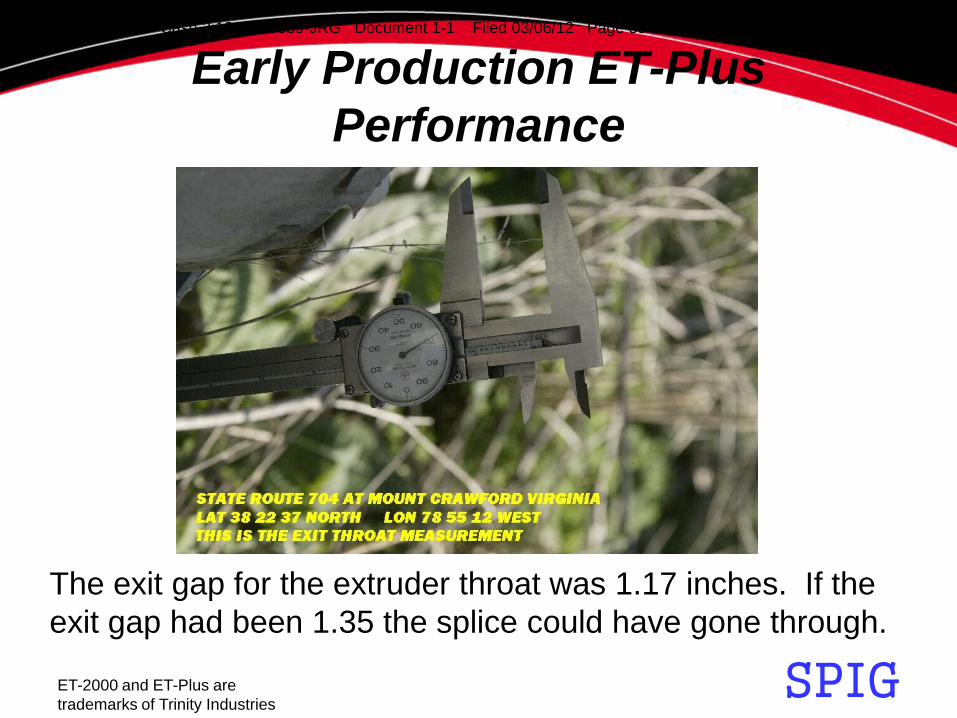
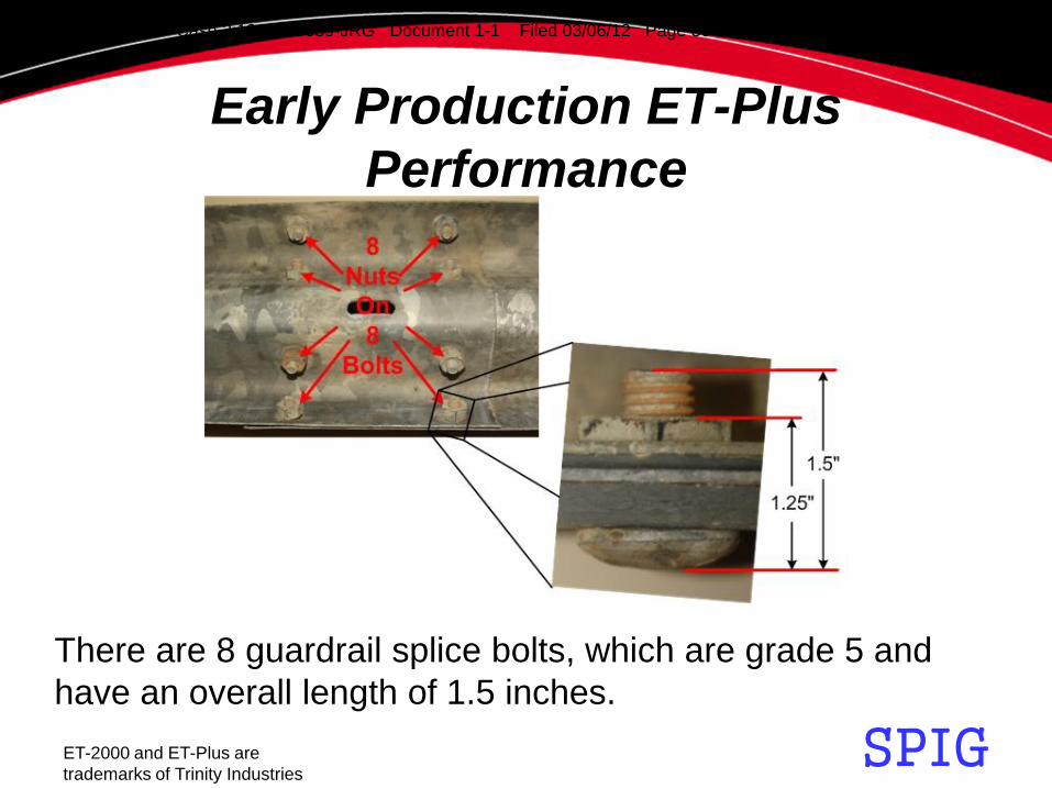
The exit gap for the extruder throat was 1.17 inches. If the
exit gap had been 1.35 the splice could have gone through.
Case 2:12-cv-00089-JRG Document 1-1 Filed 03/06/12 Page 35 of 109 PageID #: 45
SPIG ET-2000 and ET-Plus are
trademarks of Trinity Industries
Early Production ET-Plus
Performance
There are 8 guardrail splice bolts, which are grade 5 and
have an overall length of 1.5 inches.
Case 2:12-cv-00089-JRG Document 1-1 Filed 03/06/12 Page 36 of 109 PageID #: 46
SPIG ET-2000 and ET-Plus are
trademarks of Trinity Industries
Early Production ET-Plus
Performance
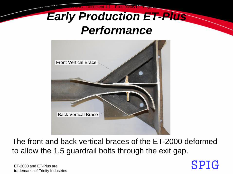
The front and back vertical braces of the ET-2000 deformed
to allow the 1.5 guardrail bolts through the exit gap.
Back Vertical Brace
Front Vertical Brace
Case 2:12-cv-00089-JRG Document 1-1 Filed 03/06/12 Page 37 of 109 PageID #: 47

SPIG ET-2000 and ET-Plus are
trademarks of Trinity Industries
Early Production ET-Plus
Performance
A 1.5 inch bolt has hard time getting through a 1.17 inch gap
and bending the 4 inch wide ½ inch thick steel back vertical
brace of the ET-Plus.
Case 2:12-cv-00089-JRG Document 1-1 Filed 03/06/12 Page 38 of 109 PageID #: 48

SPIG ET-2000 and ET-Plus are
trademarks of Trinity Industries
Redesign Into Current Production
The current production ET-Plus with a feeder chute having
4 inch wide rails started to appear in 2005.
Case 2:12-cv-00089-JRG Document 1-1 Filed 03/06/12 Page 39 of 109 PageID #: 49

SPIG ET-2000 and ET-Plus are
trademarks of Trinity Industries
Redesign Into Current Production
5 [127]
37 [940]15
.375
[391
]
4 [102]
36 [914]
14.8
75 [3
78]
The following explains how a 2005 redesign changed an
early production ET-Plus into a current production ET-Plus.
Case 2:12-cv-00089-JRG Document 1-1 Filed 03/06/12 Page 40 of 109 PageID #: 50
SPIG ET-2000 and ET-Plus are
trademarks of Trinity Industries
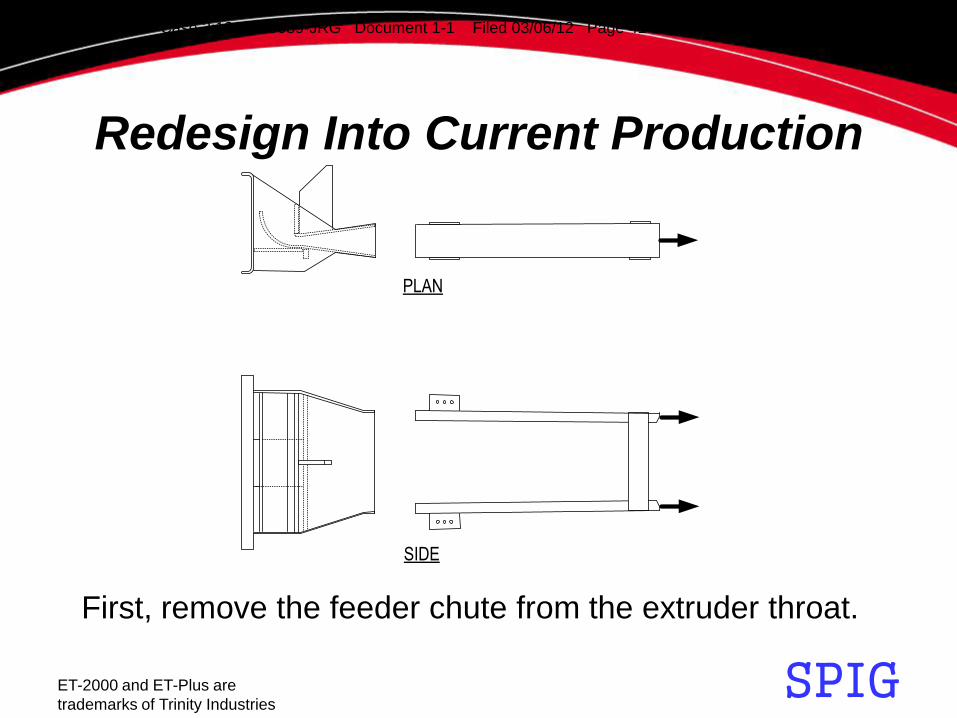
PLAN
SIDE
Redesign Into Current Production
First, remove the feeder chute from the extruder throat.
Case 2:12-cv-00089-JRG Document 1-1 Filed 03/06/12 Page 41 of 109 PageID #: 51

SPIG ET-2000 and ET-Plus are
trademarks of Trinity Industries
PLAN
SIDE
Redesign Into Current Production
Reduce feeder chute width and height between rails.
Case 2:12-cv-00089-JRG Document 1-1 Filed 03/06/12 Page 42 of 109 PageID #: 52
SPIG ET-2000 and ET-Plus are
trademarks of Trinity Industries
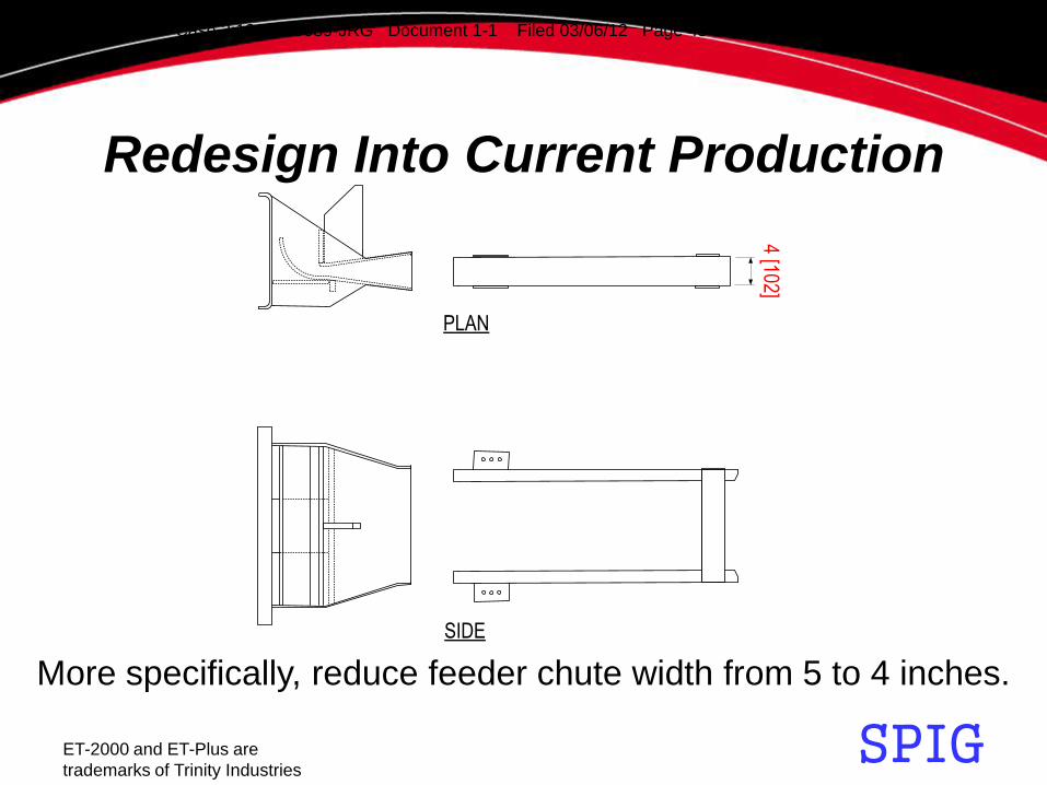
PLAN
SIDE
4 [102]
Redesign Into Current Production
More specifically, reduce feeder chute width from 5 to 4 inches.
Case 2:12-cv-00089-JRG Document 1-1 Filed 03/06/12 Page 43 of 109 PageID #: 53

SPIG ET-2000 and ET-Plus are
trademarks of Trinity Industries
PLAN
SIDE
14.8
75 [3
78]
Redesign Into Current Production
Reduce rail height from 15.375 to 14.875 inches.
Case 2:12-cv-00089-JRG Document 1-1 Filed 03/06/12 Page 44 of 109 PageID #: 54

SPIG ET-2000 and ET-Plus are
trademarks of Trinity Industries
Redesign Into Current Production
PLAN
SIDE
Insert rails .75 inches deep into extruder throat.
Case 2:12-cv-00089-JRG Document 1-1 Filed 03/06/12 Page 45 of 109 PageID #: 55
SPIG ET-2000 and ET-Plus are
trademarks of Trinity Industries
Redesign Into Current Production
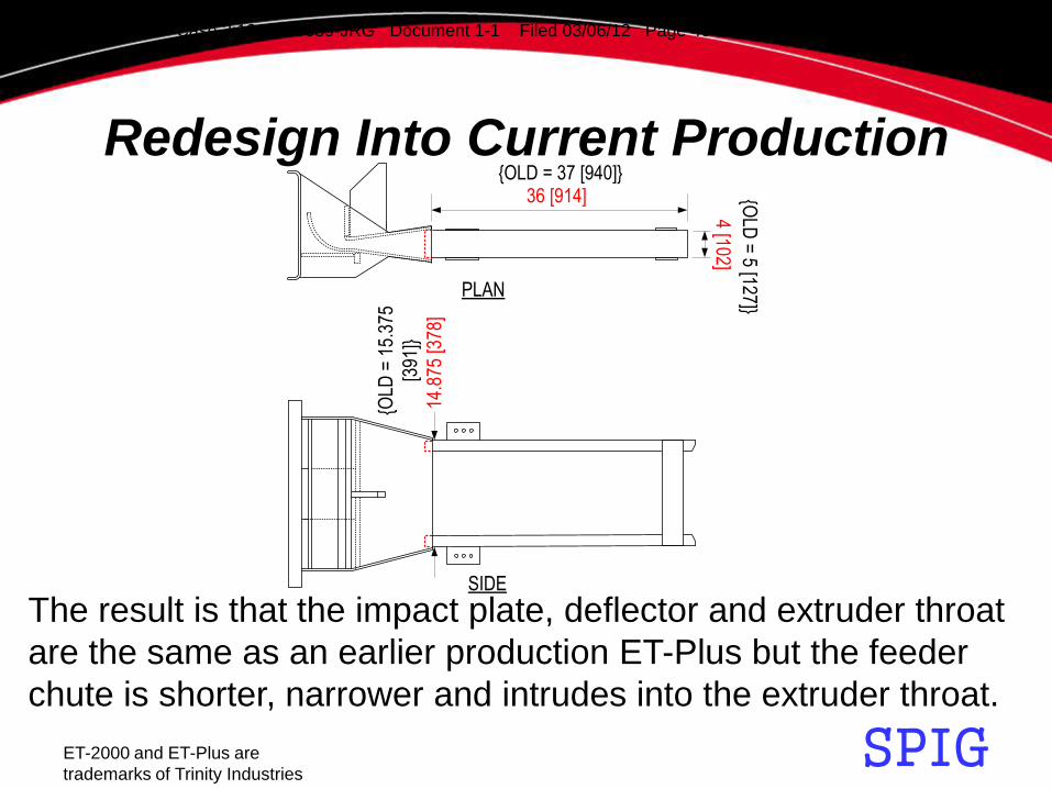
The result is that the impact plate, deflector and extruder throat
are the same as an earlier production ET-Plus but the feeder
chute is shorter, narrower and intrudes into the extruder throat.
PLAN
4 [102]
36 [914]
SIDE
14.8
75 [3
78]
{OLD = 37 [940]}
{OLD
= 5 [127]}
{OLD
= 1
5.37
5
[391
]}
Case 2:12-cv-00089-JRG Document 1-1 Filed 03/06/12 Page 46 of 109 PageID #: 56

SPIG ET-2000 and ET-Plus are
trademarks of Trinity Industries
Redesign Into Current Production
A design approval request sent to FHWA in October 2009 for
a system having 31 inch high guardrail showed the ET-Plus
as having a feeder chute with 5 inch wide feeder rails.
Case 2:12-cv-00089-JRG Document 1-1 Filed 03/06/12 Page 47 of 109 PageID #: 57

SPIG ET-2000 and ET-Plus are
trademarks of Trinity Industries
Differences Between Productions
Differences of dimensions of feeder chute between productions.
PLAN4 [102]
36 [914]
SIDE
14.8
75 [3
78]
{OLD = 37 [940]}
{OLD
= 5 [127]}
{OLD
= 1
5.37
5
[391
]}
Case 2:12-cv-00089-JRG Document 1-1 Filed 03/06/12 Page 48 of 109 PageID #: 58

SPIG ET-2000 and ET-Plus are
trademarks of Trinity Industries
Differences Between Productions
The insertion of the feeder
chute into the extruder throat
has caused changes to
critical dimensions within the
extruder throat that adversely
effect performance.
Note positions for following
cross-sections at .75 inches
into the extruder throat from
feeder chute for both.
EARLY PRODUCTION ET-Plus
CURRENT PRODUCTION ET-Plus
Case 2:12-cv-00089-JRG Document 1-1 Filed 03/06/12 Page 49 of 109 PageID #: 59

SPIG ET-2000 and ET-Plus are
trademarks of Trinity Industries
Differences Between Productions
Less area for guardrail in the extruder throat where
the feeder chute ends in the extruder throat.
EARLY PRODUCTION
ET-Plus
CURRENT PRODUCTION
ET-Plus
Case 2:12-cv-00089-JRG Document 1-1 Filed 03/06/12 Page 50 of 109 PageID #: 60

SPIG ET-2000 and ET-Plus are
trademarks of Trinity Industries
Differences Between Productions
Dimensions at .75 inches within extruder throat are different.
14.4
75
[36
8]
3.125 [79]
EARLY PRODUCTION
ET-Plus
CURRENT PRODUCTION
ET-Plus
15.6
75
[39
8]
4.25 [108]
Case 2:12-cv-00089-JRG Document 1-1 Filed 03/06/12 Page 51 of 109 PageID #: 61

SPIG ET-2000 and ET-Plus are
trademarks of Trinity Industries
Differences Between Productions EARLY PRODUCTION ET-Plus
CURRENT PRODUCTION ET-Plus
Note positions of the cross-sections again.
Case 2:12-cv-00089-JRG Document 1-1 Filed 03/06/12 Page 52 of 109 PageID #: 62
SPIG ET-2000 and ET-Plus are
trademarks of Trinity Industries
Differences Between Productions
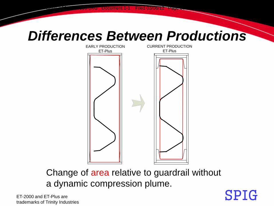
Change of area relative to guardrail without
a dynamic compression plume.
EARLY PRODUCTION
ET-Plus
CURRENT PRODUCTION
ET-Plus
Case 2:12-cv-00089-JRG Document 1-1 Filed 03/06/12 Page 53 of 109 PageID #: 63

SPIG ET-2000 and ET-Plus are
trademarks of Trinity Industries
Differences Between Productions
4.25" to 3.125" = ~26% WIDTH REDUCTION
15.675" to 14.475" = ~7.6% HEIGHT REDUCTION
67" to 45" = ~33% REDUCTION IN AREA
The ~7.6% height reduction at .75 inches inside of the extruder
throat from the feeder chute can drastically impact performance.
14.4
75
[36
8]
3.125 [79]
EARLY PRODUCTION
ET-Plus
CURRENT PRODUCTION
ET-Plus
15.6
75
[39
8]
4.25 [108]
Case 2:12-cv-00089-JRG Document 1-1 Filed 03/06/12 Page 54 of 109 PageID #: 64

SPIG ET-2000 and ET-Plus are
trademarks of Trinity Industries
Differences Between Productions
Some current production ET-Plus out on the highways now show
a ~8.5% height reduction at .75 inches inside of the extruder
throat from the feeder chute.
14.3
5 [3
65]
3.125 [79]
CURRENT PRODUCTION
ET-Plus
15.675" to 14.35" = ~8.5% HEIGHT REDUCTION
Case 2:12-cv-00089-JRG Document 1-1 Filed 03/06/12 Page 55 of 109 PageID #: 65

SPIG ET-2000 and ET-Plus are
trademarks of Trinity Industries
Differences Between Productions
The shorter height of the current production ET-Plus limits
the expansion of the dynamic compression plume.
EARLY PRODUCTION
ET-Plus
CURRENT PRODUCTION
ET-Plus
Case 2:12-cv-00089-JRG Document 1-1 Filed 03/06/12 Page 56 of 109 PageID #: 66

SPIG ET-2000 and ET-Plus are
trademarks of Trinity Industries
Differences Between Productions
There are ~.35 inch ledges near the top and bottom of the
extruder throat at .75 inches inside of the extruder throat from
due to the feeder chute intrusion that can drastically impact
performance.
.35
.35
CURRENT
PRODUCTION
ET-Plus
Case 2:12-cv-00089-JRG Document 1-1 Filed 03/06/12 Page 57 of 109 PageID #: 67

SPIG ET-2000 and ET-Plus are
trademarks of Trinity Industries
The exit gap of current production ET-PLUS now has
manufacturing variances between 1 to 1.2 inches.
Differences Between Productions
Exit Gap
Case 2:12-cv-00089-JRG Document 1-1 Filed 03/06/12 Page 58 of 109 PageID #: 68

SPIG ET-2000 and ET-Plus are
trademarks of Trinity Industries
Current Production Fails To Feed
The current production ET-Plus started to appear in 2005.
Case 2:12-cv-00089-JRG Document 1-1 Filed 03/06/12 Page 59 of 109 PageID #: 69

SPIG ET-2000 and ET-Plus are
trademarks of Trinity Industries
Current Production Fails To Feed
The height reduction of at least 1.2 inches at .75 inches within
the extruder throat coupled with reduction in the exit gap of
the extruder throat to below 1.3 inches cause the guardrail to
“Throat Lock” in the extruder throat during an impact.
Case 2:12-cv-00089-JRG Document 1-1 Filed 03/06/12 Page 60 of 109 PageID #: 70

SPIG ET-2000 and ET-Plus are
trademarks of Trinity Industries
Current Production Fails To Feed
When the exit gap of the extruder throat is 1.5 inches, the
resultant dynamic compression plume is well within the top
and bottom feed rails within the extruder throat.
1.5" Exit Gap
3/8 to 1/2 less
3/8 to 1/2 less
CURRENT
PRODUCTION
ET-Plus
Case 2:12-cv-00089-JRG Document 1-1 Filed 03/06/12 Page 61 of 109 PageID #: 71

SPIG ET-2000 and ET-Plus are
trademarks of Trinity Industries
Current Production Fails To Feed
1.2" Exit Gap
3/8 to 5/8 0VER
3/8 to 5/8 0VER
CURRENT
PRODUCTION
ET-Plus
When the exit gap of the extruder throat is 1.2 inches, the
resultant dynamic compression plume is beyond the top and
bottom feed rails within the extruder throat by ¾ to 1.25 inches.
Case 2:12-cv-00089-JRG Document 1-1 Filed 03/06/12 Page 62 of 109 PageID #: 72

SPIG ET-2000 and ET-Plus are
trademarks of Trinity Industries
Current Production Fails To Feed
Thus, in addition to the horizontal compressing forces from the
extruder throat that create the dynamic compression plume,…
Force
Force PLAN
Case 2:12-cv-00089-JRG Document 1-1 Filed 03/06/12 Page 63 of 109 PageID #: 73
SPIG ET-2000 and ET-Plus are
trademarks of Trinity Industries
Current Production Fails To Feed Force
ForceSIDE
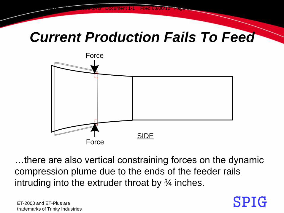
…there are also vertical constraining forces on the dynamic
compression plume due to the ends of the feeder rails
intruding into the extruder throat by ¾ inches.
Case 2:12-cv-00089-JRG Document 1-1 Filed 03/06/12 Page 64 of 109 PageID #: 74

SPIG ET-2000 and ET-Plus are
trademarks of Trinity Industries
Current Production Fails To Feed
The vertical constraining forces from the ends of the feeder
rails deforms the natural shape of the dynamic compression
plume resulting from the horizontal compressing forces.
Force
Force
Force
Force
PLAN
SIDE
Case 2:12-cv-00089-JRG Document 1-1 Filed 03/06/12 Page 65 of 109 PageID #: 75

SPIG ET-2000 and ET-Plus are
trademarks of Trinity Industries
Current Production Fails To Feed
The deformation of the natural dynamic compression
plume creates a contortion zone in the guardrail
within the extruder throat.
1.3" Exit Gap
Case 2:12-cv-00089-JRG Document 1-1 Filed 03/06/12 Page 66 of 109 PageID #: 76

SPIG ET-2000 and ET-Plus are
trademarks of Trinity Industries
Current Production Fails To Feed
The contortion zone of a current production ET-Plus with 1.2
inch exit gap will span across the distance between ends of
the feeder rails in the extruder throat so as to cause the
guardrail to lock up in the extruder throat during an impact.
1.2" Exit Gap
Case 2:12-cv-00089-JRG Document 1-1 Filed 03/06/12 Page 67 of 109 PageID #: 77

SPIG ET-2000 and ET-Plus are
trademarks of Trinity Industries
Current Production Fails To Feed
This is an example of throat lock that occurred in a current
production ET-Plus with 1.2 inch exit gap during an impact.
Case 2:12-cv-00089-JRG Document 1-1 Filed 03/06/12 Page 68 of 109 PageID #: 78

SPIG ET-2000 and ET-Plus are
trademarks of Trinity Industries
Current Production Fails To Feed
This is an example of a current production ET-Plus with 1.2
inch exit gap that did not throat lock because…
Case 2:12-cv-00089-JRG Document 1-1 Filed 03/06/12 Page 69 of 109 PageID #: 79

SPIG ET-2000 and ET-Plus are
trademarks of Trinity Industries
Current Production Fails To Feed
…the rail bent over at the top of the guardrail.
Case 2:12-cv-00089-JRG Document 1-1 Filed 03/06/12 Page 70 of 109 PageID #: 80

SPIG ET-2000 and ET-Plus are
trademarks of Trinity Industries
Current Production Fails To Feed
Then, this current production ET-Plus failed at the guardrail splice.
Case 2:12-cv-00089-JRG Document 1-1 Filed 03/06/12 Page 71 of 109 PageID #: 81

SPIG ET-2000 and ET-Plus are
trademarks of Trinity Industries
Current Production Fails To Feed
This guardrail bent over at the bottom, fed through the
extruder throat some distance, and then throat locked.
Case 2:12-cv-00089-JRG Document 1-1 Filed 03/06/12 Page 72 of 109 PageID #: 82

SPIG ET-2000 and ET-Plus are
trademarks of Trinity Industries
Current Production Fails To Feed
1.1" Exit Gap
The contortion zone of a current production ET-Plus with 1.1
inch exit gap is even larger and thus is more likely to throat
lock quicker during an impact.
Case 2:12-cv-00089-JRG Document 1-1 Filed 03/06/12 Page 73 of 109 PageID #: 83

SPIG ET-2000 and ET-Plus are
trademarks of Trinity Industries
Current Production Fails To Feed
This is an example of throat lock that occurred in a current
production ET-Plus with 1.1 inch exit gap during an impact.
Case 2:12-cv-00089-JRG Document 1-1 Filed 03/06/12 Page 74 of 109 PageID #: 84

SPIG ET-2000 and ET-Plus are
trademarks of Trinity Industries
Current Production Fails To Feed
This is an example of throat lock that occurred in a current
production ET-Plus with 1.1 inch exit gap during an impact.
Case 2:12-cv-00089-JRG Document 1-1 Filed 03/06/12 Page 75 of 109 PageID #: 85
SPIG ET-2000 and ET-Plus are
trademarks of Trinity Industries
Current Production Fails To Feed
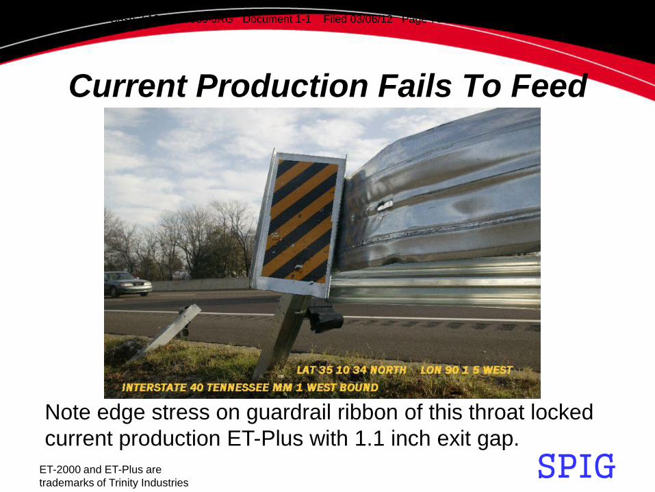
Note edge stress on guardrail ribbon of this throat locked
current production ET-Plus with 1.1 inch exit gap.
Case 2:12-cv-00089-JRG Document 1-1 Filed 03/06/12 Page 76 of 109 PageID #: 86

SPIG ET-2000 and ET-Plus are
trademarks of Trinity Industries
Current Production Fails To Feed
1.0" Exit Gap
The contortion zone of a current production ET-Plus with 1.0
inch exit gap is the largest.
Case 2:12-cv-00089-JRG Document 1-1 Filed 03/06/12 Page 77 of 109 PageID #: 87

SPIG ET-2000 and ET-Plus are
trademarks of Trinity Industries
Current Production Fails To Feed
This is a current production ET-Plus that has been cut apart
to show throat locked guardrail in the extruder throat.
Throatlock
Cut Line
Cut Line
Case 2:12-cv-00089-JRG Document 1-1 Filed 03/06/12 Page 78 of 109 PageID #: 88

SPIG ET-2000 and ET-Plus are
trademarks of Trinity Industries
Other Thoughts
The blockout’s lack of resilience may further contribute to
throat lock in that the guardrail is allowed to flex.
Case 2:12-cv-00089-JRG Document 1-1 Filed 03/06/12 Page 79 of 109 PageID #: 89
SPIG ET-2000 and ET-Plus are
trademarks of Trinity Industries
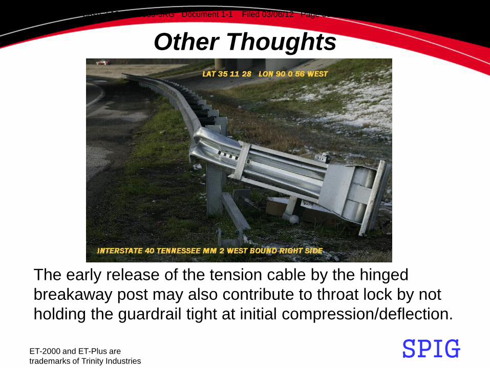
Other Thoughts
The early release of the tension cable by the hinged
breakaway post may also contribute to throat lock by not
holding the guardrail tight at initial compression/deflection.
Case 2:12-cv-00089-JRG Document 1-1 Filed 03/06/12 Page 80 of 109 PageID #: 90

SPIG ET-2000 and ET-Plus are
trademarks of Trinity Industries
Conclusion
• A current production ET-Plus having an exit
gap of less than 1.3 inches will have the
guardrail throat lock in the extruder throat
when impacted.
Case 2:12-cv-00089-JRG Document 1-1 Filed 03/06/12 Page 81 of 109 PageID #: 91

SPIG ET-2000 and ET-Plus are
trademarks of Trinity Industries
Overview • ET-Plus Background
• Parts of Early Production ET-Plus
• Early Production ET-Plus Performance
• Redesign Into Current Production
• Differences Between Productions
• Current Production Fails To Feed
• Other Thoughts
• Conclusion
• Addendum
• Photo Appendix
Case 2:12-cv-00089-JRG Document 1-1 Filed 03/06/12 Page 82 of 109 PageID #: 92
SPIG ET-2000 and ET-Plus are
trademarks of Trinity Industries
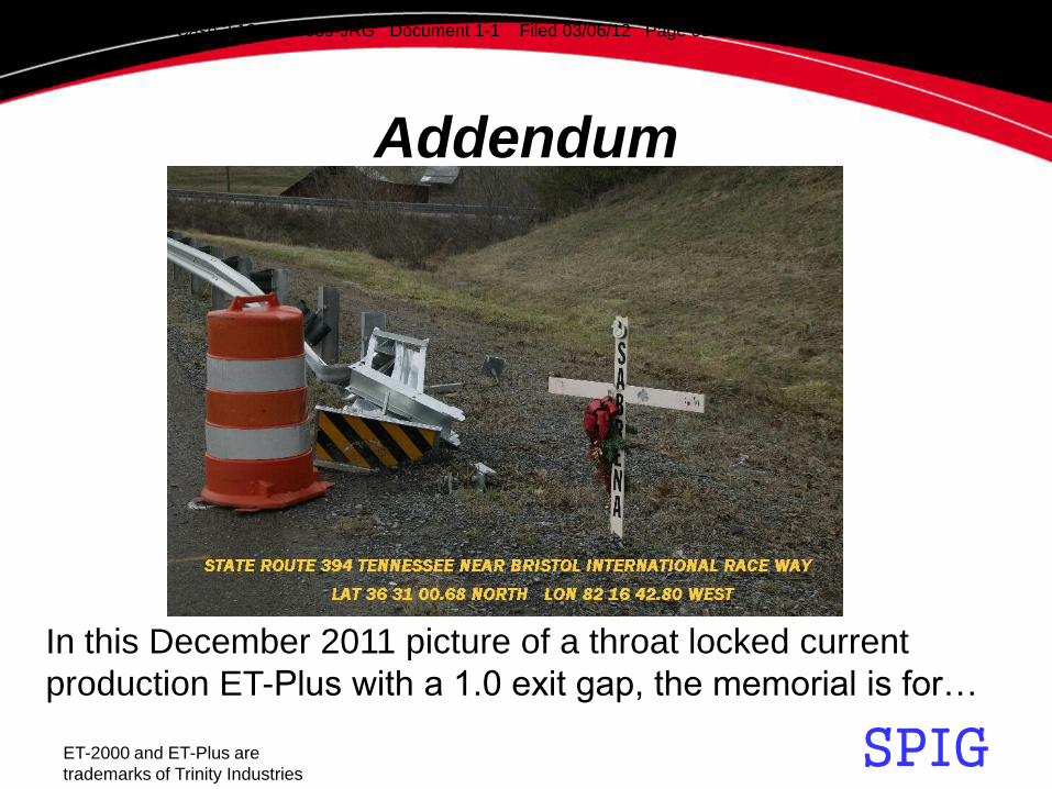
Addendum
In this December 2011 picture of a throat locked current
production ET-Plus with a 1.0 exit gap, the memorial is for…
Case 2:12-cv-00089-JRG Document 1-1 Filed 03/06/12 Page 83 of 109 PageID #: 93

SPIG ET-2000 and ET-Plus are
trademarks of Trinity Industries
Addendum
… young lady killed in a 2008 accident involving another
current production ET-Plus with 1.0 inch exit gap.
Case 2:12-cv-00089-JRG Document 1-1 Filed 03/06/12 Page 84 of 109 PageID #: 94

SPIG ET-2000 and ET-Plus are
trademarks of Trinity Industries
Addendum
This current production ET-Plus had an exit gap of
1.1 inch and the guardrail is throat locked in the
extruder head.
Case 2:12-cv-00089-JRG Document 1-1 Filed 03/06/12 Page 85 of 109 PageID #: 95
SPIG ET-2000 and ET-Plus are
trademarks of Trinity Industries
Thank you
Questions ?
Case 2:12-cv-00089-JRG Document 1-1 Filed 03/06/12 Page 86 of 109 PageID #: 96
SPIG ET-2000 and ET-Plus are
trademarks of Trinity Industries
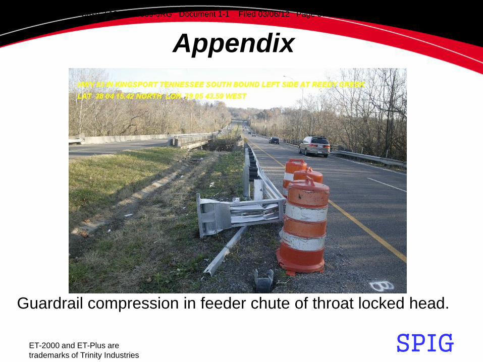
Appendix
Guardrail compression in feeder chute of throat locked head.
Case 2:12-cv-00089-JRG Document 1-1 Filed 03/06/12 Page 87 of 109 PageID #: 97

SPIG ET-2000 and ET-Plus are
trademarks of Trinity Industries
Appendix
Guardrail bulge in feeder chute of throat locked head.
Case 2:12-cv-00089-JRG Document 1-1 Filed 03/06/12 Page 88 of 109 PageID #: 98

SPIG ET-2000 and ET-Plus are
trademarks of Trinity Industries
Appendix
Kinking guardrail at splice because of throat locked head.
Case 2:12-cv-00089-JRG Document 1-1 Filed 03/06/12 Page 89 of 109 PageID #: 99

SPIG ET-2000 and ET-Plus are
trademarks of Trinity Industries
Appendix
Guardrail compression in feeder chute of throat locked head.
Case 2:12-cv-00089-JRG Document 1-1 Filed 03/06/12 Page 90 of 109 PageID #: 100

SPIG ET-2000 and ET-Plus are
trademarks of Trinity Industries
Appendix
Case 2:12-cv-00089-JRG Document 1-1 Filed 03/06/12 Page 91 of 109 PageID #: 101

SPIG ET-2000 and ET-Plus are
trademarks of Trinity Industries
Appendix
Case 2:12-cv-00089-JRG Document 1-1 Filed 03/06/12 Page 92 of 109 PageID #: 102

SPIG ET-2000 and ET-Plus are
trademarks of Trinity Industries
Appendix
Case 2:12-cv-00089-JRG Document 1-1 Filed 03/06/12 Page 93 of 109 PageID #: 103

SPIG ET-2000 and ET-Plus are
trademarks of Trinity Industries
Appendix
Remnants of plume outside in the feeder chute.
Case 2:12-cv-00089-JRG Document 1-1 Filed 03/06/12 Page 94 of 109 PageID #: 104

SPIG ET-2000 and ET-Plus are
trademarks of Trinity Industries
Appendix
Remnants of plume outside in the feeder chute.
Case 2:12-cv-00089-JRG Document 1-1 Filed 03/06/12 Page 95 of 109 PageID #: 105
SPIG ET-2000 and ET-Plus are
trademarks of Trinity Industries
Appendix
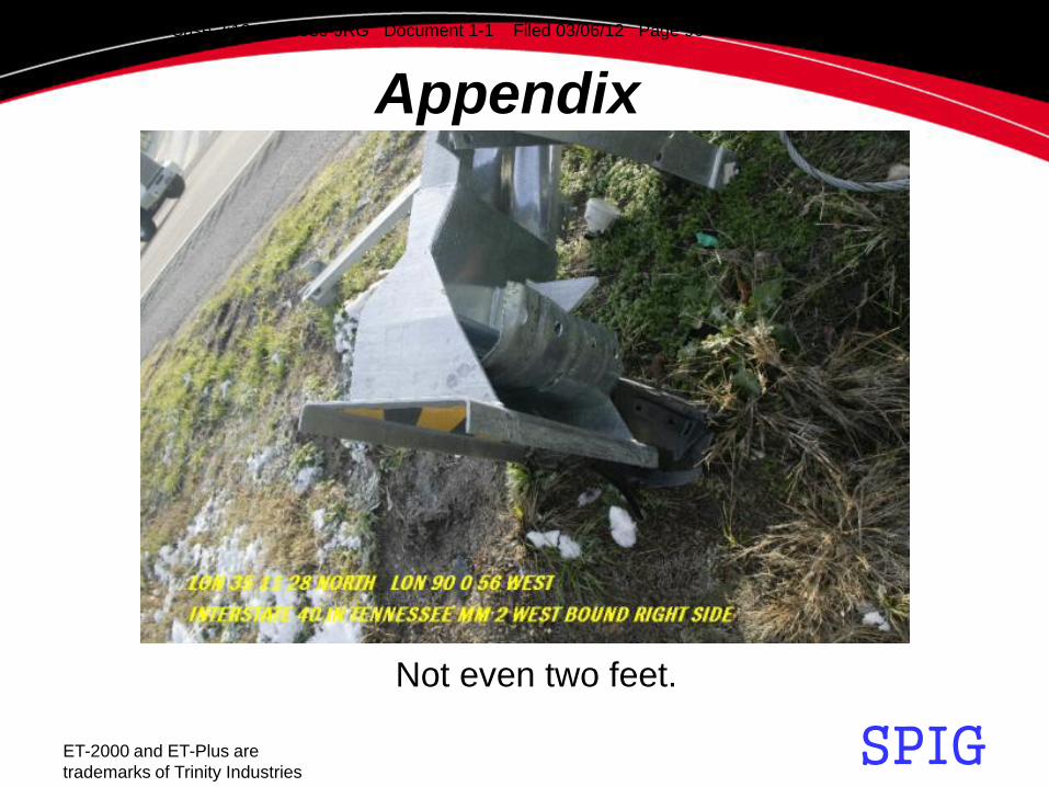
Not even two feet.
Case 2:12-cv-00089-JRG Document 1-1 Filed 03/06/12 Page 96 of 109 PageID #: 106

SPIG ET-2000 and ET-Plus are
trademarks of Trinity Industries
Appendix
Ran a good bit but…
Case 2:12-cv-00089-JRG Document 1-1 Filed 03/06/12 Page 97 of 109 PageID #: 107

SPIG ET-2000 and ET-Plus are
trademarks of Trinity Industries
Appendix
…it had to fold the beam on itself and . . . .
Case 2:12-cv-00089-JRG Document 1-1 Filed 03/06/12 Page 98 of 109 PageID #: 108

SPIG ET-2000 and ET-Plus are
trademarks of Trinity Industries
Appendix
…guardrail still throat locked in the extruder throat.
Case 2:12-cv-00089-JRG Document 1-1 Filed 03/06/12 Page 99 of 109 PageID #: 109

SPIG ET-2000 and ET-Plus are
trademarks of Trinity Industries
Appendix
Case 2:12-cv-00089-JRG Document 1-1 Filed 03/06/12 Page 100 of 109 PageID #: 110

SPIG ET-2000 and ET-Plus are
trademarks of Trinity Industries
Appendix
Case 2:12-cv-00089-JRG Document 1-1 Filed 03/06/12 Page 101 of 109 PageID #: 111

SPIG ET-2000 and ET-Plus are
trademarks of Trinity Industries
Appendix
Case 2:12-cv-00089-JRG Document 1-1 Filed 03/06/12 Page 102 of 109 PageID #: 112

SPIG ET-2000 and ET-Plus are
trademarks of Trinity Industries
Appendix
Case 2:12-cv-00089-JRG Document 1-1 Filed 03/06/12 Page 103 of 109 PageID #: 113

SPIG ET-2000 and ET-Plus are
trademarks of Trinity Industries
Appendix
Case 2:12-cv-00089-JRG Document 1-1 Filed 03/06/12 Page 104 of 109 PageID #: 114

SPIG ET-2000 and ET-Plus are
trademarks of Trinity Industries
Appendix
Case 2:12-cv-00089-JRG Document 1-1 Filed 03/06/12 Page 105 of 109 PageID #: 115

SPIG ET-2000 and ET-Plus are
trademarks of Trinity Industries
Appendix
Case 2:12-cv-00089-JRG Document 1-1 Filed 03/06/12 Page 106 of 109 PageID #: 116

SPIG ET-2000 and ET-Plus are
trademarks of Trinity Industries
Appendix
Case 2:12-cv-00089-JRG Document 1-1 Filed 03/06/12 Page 107 of 109 PageID #: 117

SPIG ET-2000 and ET-Plus are
trademarks of Trinity Industries
Appendix
Case 2:12-cv-00089-JRG Document 1-1 Filed 03/06/12 Page 108 of 109 PageID #: 118

SPIG ET-2000 and ET-Plus are
trademarks of Trinity Industries
Appendix
Case 2:12-cv-00089-JRG Document 1-1 Filed 03/06/12 Page 109 of 109 PageID #: 119

Mr. Steve L. Brown President Trinity Highway Safety Products Division P.O. Box 568887 Dallas, Texas 75356-8887
Dear Mr. Brown: In his August 10, 2005, letter to Mr. Richard Powers, Mr. Don Johnson requested Federal Highway Administration (FHWA) acceptance of a modified version of your ET-Plus guardrail terminal named the ET-Plus 31. The modifications noted below were needed to match the ET-Plus terminal, which was originally tested with standard W-beam guardrail, to the Midwest Guardrail System (MGS). The MGS barrier was formally accepted as an National Cooperative Highway Research Program (NCHRP) Report 350 test level 3 (TL-3) barrier on March 1, 2005, (acceptance letter B-133). To verify the crashworthiness of the modified ET-Plus, the Texas Transportation Institute conducted the following two tests, which are described in that agency’s July 2005 report, “NCHRP Report 350 Testing of the ET-Plus for 30-inch High W-Beam Guardrail”:
• Report 350 test 3-30 (TTI Test 220601-2) • Report 350 test 3-35 (TTI Test 220601-1)
To match the MGS barrier design, the following modifications, shown in Enclosure 1, were made to the original ET-Plus terminal:
1. The guardrail height was raised to 787 mm (31 inches) throughout the terminal
length. 2. The depth of each offset block (beginning at post 3) was increased to 305 mm
(12 inches). 3. The upper section of the Hinged Breakaway Anchor post was modified to
accommodate the increased guardrail height. 4. A 3.8-m (12.5-ft) long W-beam rail, with anchor bracket holes, was used between
posts 1 and 3. A special 2.86-m (9.375-ft) W-beam section begins at post 3 and results in a splice located midway between posts 4 and 5. Standard W-beam
400 Seventh St., S.W. Washington, D.C. 20590
In Reply Refer To: HSA-10/CC-94
September 2, 2005
Case 2:12-cv-00089-JRG Document 1-2 Filed 03/06/12 Page 1 of 10 PageID #: 120

2 sections with holes punched on 0.95 m (3.125 ft) centers are then used from mid-span of posts 4 and 5 and beyond. The terminal proper ends at post 7 (the first standard line post) making its total length 11.43 m (37.5 ft).
5. Ground-line weakening holes in the SYTP are located 810 mm (31.875 inches) from the top of each post. Since the overall post length is unchanged, each SYTP post is embedded approximately 1020 mm in the ground.
6. Modified SYTP posts are used for post positions 2 through 6. 7. Standard W6 x 8.5 line posts are used at post 7 and beyond.
The NCHRP Report 350 requires up to seven crash tests to determine the adequacy of a traffic barrier terminal at TL-3. However, since the original designs for attachment to standard W-beam guardrail have proven to be crashworthy, only those tests that are likely to be affected by the design changes noted above are considered necessary. You successfully completed test 3-30 (head-on test with the 820-kg car) and test 3-35 (20-degree impact with the pickup truck at post 3). Summary sheets for each of these tests are shown in Enclosure 2 to this letter.
The modifications described above are acceptable and the ET-Plus 31 may be considered a TL-3 design that can be used on the National Highway System (NHS) when connected to the MGS barrier. While the barrier itself is non-proprietary, your terminal is proprietary and remains subject to the conditions stated in Title 23, Code of Federal Regulations, Section 635.411 when used on Federal-aid highway projects, except exempt, non-NHS projects.
Sincerely yours,
/original signed by/
John R. Baxter, P.E. Director, Office of Safety Design Office of Safety
2 Enclosures
Case 2:12-cv-00089-JRG Document 1-2 Filed 03/06/12 Page 2 of 10 PageID #: 121
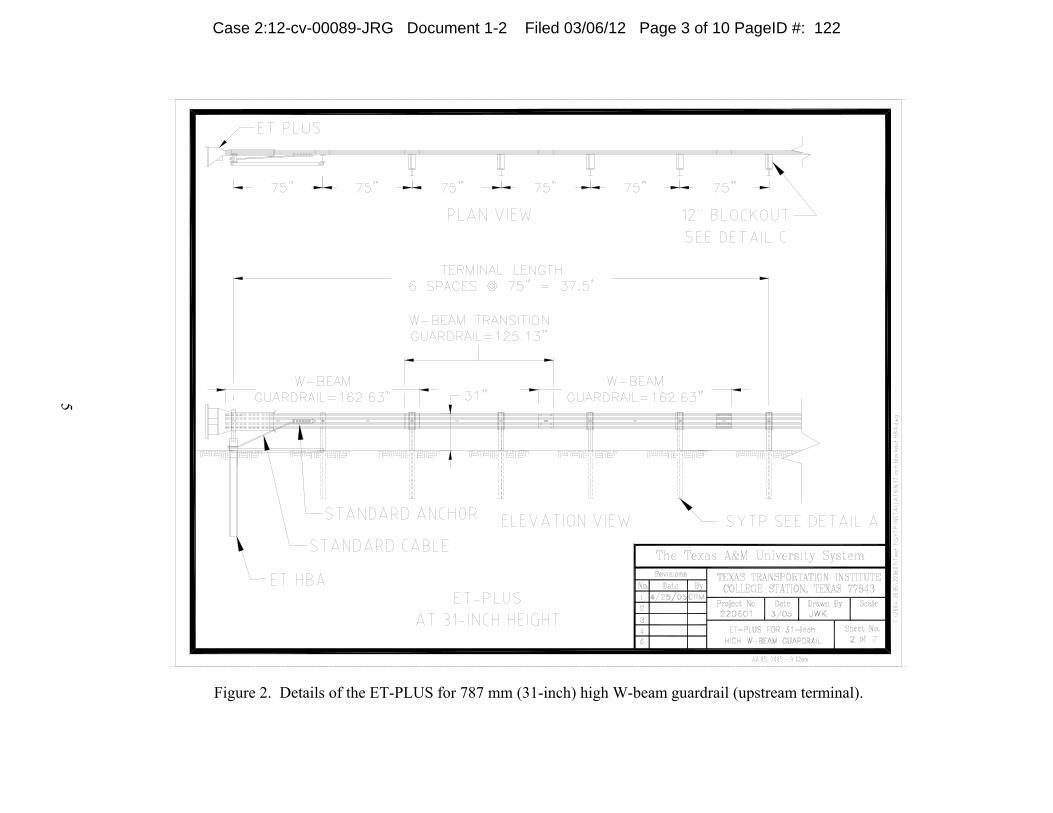
5
Figure 2. Details of the ET-PLUS for 787 mm (31-inch) high W-beam guardrail (upstream terminal).
Case 2:12-cv-00089-JRG Document 1-2 Filed 03/06/12 Page 3 of 10 PageID #: 122

Case 2:12-cv-00089-JRG Document 1-2 Filed 03/06/12 Page 4 of 10 PageID #: 123

Figure 4. Details of the ET-PLUS for 787 mm (31-inch) high W-beam guardrail (SYTP post).
7
Case 2:12-cv-00089-JRG Document 1-2 Filed 03/06/12 Page 5 of 10 PageID #: 124

35
0.000 s 0.226 s 0.451 s 0.679 s
General Information Test Agency............................... Test No. .................................... Date ........................................... Test Article Type........................................... Name ......................................... Installation Length (m) ............... Material or Key Elements .......... Soil Type and Condition............. Test Vehicle Type........................................... Designation................................ Model ......................................... Mass (kg) Curb........................................ Test Inertial............................. Dummy ................................... Gross Static............................
Texas Transportation Institute 220601-2 05-27-2005 Terminal ET-31 70.5 ET-PLUS Head on HBA Posts with SYTP Posts and 787 mm high W-beam Standard Soil, Dry Production 2000P 1998 Geo Metro 810 820 77 897
Impact Conditions Speed (km/h) ............................. Angle (deg) ................................ Exit Conditions Speed (km/h) ............................. Angle (deg) ................................ Occupant Risk Values Impact Velocity (m/s) Longitudinal ............................ Lateral .................................... THIV (km/h) ............................... Ridedown Accelerations (g’s) Longitudinal ............................ Lateral .................................... PHD (g’s) ................................... ASI ............................................ Max. 0.050-s Average (g’s) Longitudinal ............................ Lateral .................................... Vertical ...................................
101.8 0.5 N/A N/A 8.3 0.3 30.1 -14.0 4.3 14.3 0.92 -10.7 3.3 2.4
Test Article Deflections (m) Dynamic ........................................... Permanent........................................ Working Width .................................. Vehicle Damage Exterior VDS............................................... CDC .............................................. Max. Exterior Vehicle Crush (mm) ................... Interior OCDI ............................................. Max. Occupant Compartment Deformation (mm) ...................... Post-Impact Behavior (during 1.0 sec after impact) Max. Yaw Angle (deg)................... Max. Pitch Angle (deg).................. Max. Roll Angle (deg) ...................
5.44 5.40 0.36 12FD3 12FDEW3 420 FS0000000 0 140 7 -15
Figure 22. Summary of results for NCHRP Report 350 test 3-30 on the ET-PLUS for 787 mm (31-inch) high W-beam guardrail.
Case 2:12-cv-00089-JRG Document 1-2 Filed 03/06/12 Page 6 of 10 PageID #: 125

23
0.000 s 0.144 s 0.400 s 0.645 s
General Information Test Agency............................... Test No. .................................... Date ........................................... Test Article Type........................................... Name ......................................... Installation Length (m) ............... Material or Key Elements .......... Soil Type and Condition............. Test Vehicle Type........................................... Designation................................ Model ......................................... Mass (kg) Curb........................................ Test Inertial............................. Dummy ................................... Gross Static............................
Texas Transportation Institute 220601-1 05-05-2005 Terminal ET-31 70.5 ET-PLUS Head on HBA Posts with SYTP Posts and 787 mm high W-beam Standard Soil, Dry Production 2000P 1992 Chevrolet 2500 Pickup Truck 1912 2031 No dummy 2031
Impact Conditions Speed (km/h) ............................. Angle (deg) ................................ Exit Conditions Speed (km/h) ............................. Angle (deg) ................................ Occupant Risk Values Impact Velocity (m/s) Longitudinal ............................ Lateral .................................... THIV (km/h) ............................... Ridedown Accelerations (g’s) Longitudinal ............................ Lateral .................................... PHD (g’s) ................................... ASI ............................................ Max. 0.050-s Average (g’s) Longitudinal ............................ Lateral .................................... Vertical ...................................
100.5 19.2 N/A N/A 8.7 4.6 31.1 -11.5 -6.5 11.9 0.83 -7.7 -4.6 -3.6
Test Article Deflections (m) Dynamic ........................................... Permanent........................................ Working Width .................................. Vehicle Damage Exterior VDS............................................... CDC .............................................. Max. Exterior Vehicle Crush (mm) ................... Interior OCDI ............................................. Max. Occupant Compartment Deformation (mm) ...................... Post-Impact Behavior (during 1.0 sec after impact) Max. Yaw Angle (deg)................... Max. Pitch Angle (deg).................. Max. Roll Angle (deg) ...................
0.94 0.26 0.68 01RFQ3 01RFEW3 530 FS0000000 0 -16 21 -16
Figure 15. Summary of results for NCHRP Report 350 test 3-35 on the ET-PLUS for 787 mm (31-inch) high W-beam guardrail.
Case 2:12-cv-00089-JRG Document 1-2 Filed 03/06/12 Page 7 of 10 PageID #: 126
1200 New Jersey Avenue, SE. Washington, DC 20590
August 30, 2007
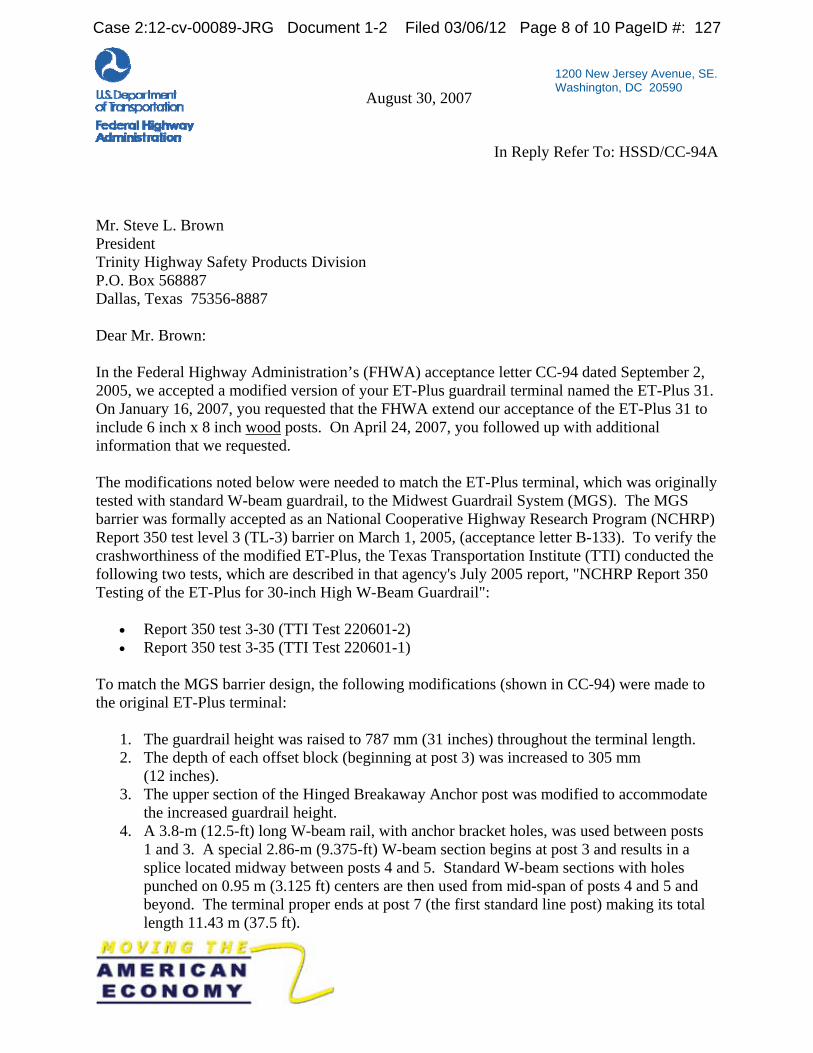
In Reply Refer To: HSSD/CC-94A
Mr. Steve L. Brown President Trinity Highway Safety Products Division P.O. Box 568887 Dallas, Texas 75356-8887 Dear Mr. Brown: In the Federal Highway Administration’s (FHWA) acceptance letter CC-94 dated September 2, 2005, we accepted a modified version of your ET-Plus guardrail terminal named the ET-Plus 31. On January 16, 2007, you requested that the FHWA extend our acceptance of the ET-Plus 31 to include 6 inch x 8 inch wood posts. On April 24, 2007, you followed up with additional information that we requested. The modifications noted below were needed to match the ET-Plus terminal, which was originally tested with standard W-beam guardrail, to the Midwest Guardrail System (MGS). The MGS barrier was formally accepted as an National Cooperative Highway Research Program (NCHRP) Report 350 test level 3 (TL-3) barrier on March 1, 2005, (acceptance letter B-133). To verify the crashworthiness of the modified ET-Plus, the Texas Transportation Institute (TTI) conducted the following two tests, which are described in that agency's July 2005 report, "NCHRP Report 350 Testing of the ET-Plus for 30-inch High W-Beam Guardrail":
• Report 350 test 3-30 (TTI Test 220601-2) • Report 350 test 3-35 (TTI Test 220601-1)
To match the MGS barrier design, the following modifications (shown in CC-94) were made to the original ET-Plus terminal:
1. The guardrail height was raised to 787 mm (31 inches) throughout the terminal length. 2. The depth of each offset block (beginning at post 3) was increased to 305 mm
(12 inches). 3. The upper section of the Hinged Breakaway Anchor post was modified to accommodate
the increased guardrail height. 4. A 3.8-m (12.5-ft) long W-beam rail, with anchor bracket holes, was used between posts
1 and 3. A special 2.86-m (9.375-ft) W-beam section begins at post 3 and results in a splice located midway between posts 4 and 5. Standard W-beam sections with holes punched on 0.95 m (3.125 ft) centers are then used from mid-span of posts 4 and 5 and beyond. The terminal proper ends at post 7 (the first standard line post) making its total length 11.43 m (37.5 ft).
Case 2:12-cv-00089-JRG Document 1-2 Filed 03/06/12 Page 8 of 10 PageID #: 127

2
5. Ground-line weakening holes in the Steel Yielding Terminal Posts (SYTP) are located 810 mm (31.875 inches) from the top of each post. Since the overall post length is unchanged, each SYTP post is embedded approximately 1020 mm in the ground.
6. Modified SYTP posts are used for post positions 2 through 6. 7. Standard W6 x 8.5 line posts are used at post 7 and beyond. The NCHRP Report 350
requires up to seven crash tests to determine the adequacy of a traffic barrier terminal at TL-3. However, since the original designs for attachment to standard W-beam guardrail have proven to be crashworthy, only those tests that are likely to be affected by the design changes noted above are considered necessary. You successfully completed test 3-30 (head-on test with the 820-kg car) and test 3-35 (20-degree impact with the pickup truck at post 3).
Your present request is to allow either the SYTP or 6 inch x 8 inch wood posts in the ET-Plus 31 as shown in the enclosed drawing. Because the 6x8 wood posts have been shown to perform in a similar manner to steel posts (including the SYTP) the wood post ET-Plus 31 may be considered a TL-3 design that can be used on the National Highway System when connected to the MGS barrier. While the barrier itself is non-proprietary, your terminal is proprietary and remains subject to the conditions stated in Title 23, Code of Federal Regulations, Section 635.411 when used on Federal-aid highway projects. All other conditions in the FHWA acceptance letter CC-94 continue to apply.
Sincerely yours, George E. Rice, Jr. Acting Director, Office of Safety Design Office of Safety
Enclosure FHWA:HSSD:NArtimovich:tb:x61331:8/28/07 File: s://directory folder/nartimovich/CC94A-ET31WoodFIN.doc cc: HSSD (Reader, HSA; Chron File, HSSD; N.Artimovich, HSSD; MMcDonough, HSSD)
Case 2:12-cv-00089-JRG Document 1-2 Filed 03/06/12 Page 9 of 10 PageID #: 128
Case 2:12-cv-00089-JRG Document 1-2 Filed 03/06/12 Page 10 of 10 PageID #: 129

Case 2:12-cv-00089-JRG Document 1-3 Filed 03/06/12 Page 1 of 1 PageID #: 130