
Fall 2010 Design Report - Biosystems and Agricultural ... · Fall 2010 Design Report ... Figure 2:...
57
Fall 2010 Design Report 15 November 2010 Team Members: Gary Gray – Team Leader, Engineer Evan Foster – Engineer Jeremy McCasland – Economics Laura Merriman – Engineer Alice White – Communications Client: Brad Lahman Boxel Manufacuring Caney, OK
Transcript of Fall 2010 Design Report - Biosystems and Agricultural ... · Fall 2010 Design Report ... Figure 2:...

Fall 2010 Design Report
15 November 2010
Team Members:
Gary Gray – Team Leader, Engineer
Evan Foster – Engineer
Jeremy McCasland – Economics
Laura Merriman – Engineer
Alice White – Communications
Client:
Brad Lahman
Boxel Manufacuring
Caney, OK

Page 2 of 57
TABLE OF CONTENTS
Problem Statement.......................................................................................................... 6
Mission Statement ........................................................................................................... 6
Statement of Work........................................................................................................... 6
Background .................................................................................................................. 6
Scope of Work ............................................................................................................. 6
Physical Location ......................................................................................................... 7
Period of Performance ................................................................................................. 7
Delivery Requirements ................................................................................................. 7
Table 1: Design Requirements: ................................................................................ 7
Detailed Work .............................................................................................................. 8
Payment Schedule ....................................................................................................... 8
Acceptance of Criteria .................................................................................................. 8
Special Requirements .................................................................................................. 9
Work Breakdown Schedule ............................................................................................. 9
Competitive Analysis ..................................................................................................... 13
Industry Analysis ........................................................................................................... 13
Customers/Buyers ......................................................................................................... 14
Boxel Manufacturing and Its Resources ........................................................................ 15
Competitors and Their Resources ................................................................................. 16
Figure 1: Bale Baron .............................................................................................. 16
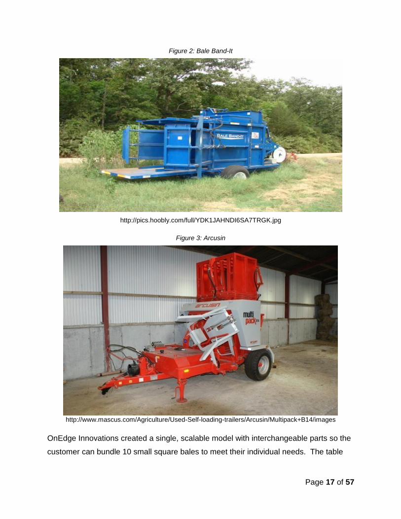
Figure 2: Bale Band-It ............................................................................................ 17
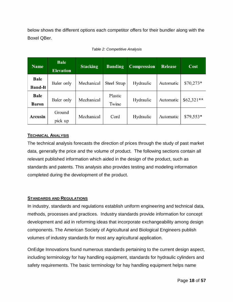
Figure 3: Arcusin .................................................................................................... 17
Table 2: Competitive Analysis ................................................................................ 18
Technical Analysis......................................................................................................... 18

Page 3 of 57
Standards and Regulations ........................................................................................... 18
Patents .......................................................................................................................... 19
Field/Physical Testing and Data .................................................................................... 20
Simulation and Modeling ............................................................................................... 21
Environmental and Global Impacts................................................................................ 21
Design Criteria .............................................................................................................. 22
Concept Development ................................................................................................... 22
Potential Solutions......................................................................................................... 22
Trailer Framework ...................................................................................................... 22
Figure 4: Trailer Framework ................................................................................... 23
Figure 5: Trailer Framework with Tires ................................................................... 24
Figure 6: Complete Trailer Framework ................................................................... 24
Telescoping/Pivoting Tongue Function ...................................................................... 24
Figure 7: Trailer Frame and Telescoping, Pivoting Tongue ................................... 25
Hay Bale Elevation ..................................................................................................... 25
Figure 8: Lifting Mechanism ................................................................................... 26
Hay Bale Stacking ...................................................................................................... 26
Figure 9: Bale Stacking Scheme ............................................................................ 27
Hay Compression ...................................................................................................... 27
Figure 11: Compression Walls on the Tracks (Dynamic – Right, Stationary – Left)28
Figure 12: Track, Trailer Framework, and Hydraulic Cylinder ................................ 29
Figure 13: Compression Assembly Mounted on the Trailer Frame ........................ 29
Bundle Banding .......................................................................................................... 30
Table 3: Bander Comparision ................................................................................ 30
Figure 15: Banding System .................................................................................... 31

Page 4 of 57
Bundle Release .......................................................................................................... 32
Figure 16: Releasing System – Resting Position ................................................... 32
Figure 17: Releasing System – Releasing Position ................................................ 33
Final Design ............................................................................................................... 33
Figure 18: Final Model Design ............................................................................... 33
Potential Issues ............................................................................................................. 33
Solution Analysis ........................................................................................................... 34
Tractor Requirements .................................................................................................... 34
Hydraulic Components / Calculations............................................................................ 34
Proposed Media / Communications Plan ...................................................................... 35
Proposed Business Plan / Financial Analysis ................................................................ 35
Project Schedule ........................................................................................................... 36
Cost Analysis ................................................................................................................ 36
Table 4: Price Comparison of Bales ....................................................................... 37
Table 5a: Cost of Manufacturing - Steel ................................................................. 37
Table 5b: Cost of Manufacturing – Hydraulics ....................................................... 37
Table 5c: Cost of Manufacturing – Banding ........................................................... 38
Table 5d: Cost of Manufacturing – Miscellaneous.................................................. 39
Table 5e: Manufacturing Costs – Estimated Total.................................................. 39
Conclusion .................................................................................................................... 39
Source Cited ................................................................................................................. 41

Page 5 of 57
APPENDICES
Appendix A – Work Breakdown Schedule
Appendix B – Testimonials
Appendix C – Standards and Regulations
Appendix D – Patents
Appendix E – Purchased Products Information
Appendix F – Hydraulic Components Information
Appendix G – Design Constraints
Appendix H – Hydraulic Equations
Appendix I – Prototype Pictures
Appendix J – Outside Company Consulting

Page 6 of 57
PROBLEM STATEMENT
In order to provide excellent hay products at a minimal production cost, Boxel
Manufacturing needs a safe, efficient, and accurate hay bale collection and banding
system. In addition to designing such a product, OnEdge Innovations will create a
business and marketing plan for Boxel regarding the promotion and sale of the hay bale
collection and banding system.
MISSION STATEMENT
OnEdge Innovations works closely with their customers to make ideas become more
than just a design, a prototype, or an unused patent. We convey our customer’s ideas
from the drawing board to production and into consumers’ hands. With combined
efforts, OnEdge Innovations strives to maintain pristine relationships with our customers
and to provide quality, safe products for consumers.
STATEMENT OF WORK
Background
OnEdge Innovations built a hay bale bundler for Boxel Manufacturing. Boxel wished to
produce and sell a machine capable of compressing small, square hay or straw bales
and banding the “bundle” together to increase ease and efficiency of storing,
transporting and loading/unloading bales. This machine fits the needs of smaller hay
producers and consumers who want convenience. From the proposed idea, OnEdge
Innovations created the Boxel QBer.
Scope of Work
The engineers of OnEdge Innovations collaborated to create a pull-along trailer
mounted on a swinging tongue. The steel trailer has a bale elevator attached to the left
side of the trailer that picks small, square bales out of the field and conveys them back
to a laborer. In addition to the trailer and the bale elevator, OnEdge Innovations
constructed a compression system capable of compressing ten small, square bales,
and a strapping system using plastic that tightens around the bundle. A hand-held

Page 7 of 57
sealer seals the bands. In order to remove the bundle of bales from the trailer, OnEdge
Innovations designed a releasing mechanism to distribute the bundle to the ground
without damaging it.
Physical Location
The construction of this project occurred in Oklahoma State University’s Biosystems
and Agricultural Engineering Laboratory and Boxel Manufacturing in Caney, Okla.
OnEdge Innovations and Boxel communicated designs through SolidWorks drawings
and distributed the construction according to the components needed at the time.
Period of Performance
The engineers of OnEdge Innovations began designing in SolidWorks in the fall
semester. Concept design models were sent to Boxel on November 8th, 2010. By the
end of the fall semester, December 5th, 2010, OnEdge Innovation had a small-scale
model constructed for final design concept review. The design was sent to Boxel March
7, 2011. with projected completion in March 2011.
Delivery Requirements
Table 1: Design Requirements:
Date Item Due
02 Oct 2010 Competitive Analysis Report
28 Oct 2010 Statement of Work
05 Nov 2010 Work Breakdown Structure
08 Nov 2010 Task List
15 Nov 2010 Design Proposal Report Draft
9-10 Dec 2010 Design Proposal Report
Design Proposal Presentation
13 Dec 2010 Team Website
13 Dec 2010 Project Notebooks
Self and Peer Evaluations
13-17 Dec 2010 Team Leader Interviews

Page 8 of 57
Detailed Work
OnEdge Innovations began designing the bale bundling mechanism in the fall semester.
The trailer is 8 feet wide, feet high and 12 to 14 feet long. OnEdge Innovations
designed all components of the bale bundler before setting exact and final dimensions
of the trailer. The trailer has enough space available for three bales waiting for stacking,
a laborer to move about the trailer in order to stack the bales, and for the compression
system, which will hold 10 bales.
The bale elevator resembles a conveyor belt system which will pick the bales from the
field or a hay baler and move them to the stacking area. This part of the machine
reduces the manual labor require to place bales on the trailer. Dimensions and workings
are currently unknown.
A tractor pulling the trailer will power the compression mechanism with hydraulics. It will
hold 10 bales, making the approximate dimensions 46” x 54” x 40”. One side of the
compression mechanism will hold a drum containing plastic strapping. The other will
have a mechanism to hold the strap ends while the bales are stacked. The compression
will either occur from one side or both sides. ***Add magnet shenanigans***
Payment Schedule
Boxel Manufacturing will purchase the majority of supplies, including metals, hydraulics,
cylinders and bearings. Oklahoma State University will provide various small parts
necessary for construction, such as nuts, bolts and equipment for testing. OnEdge
Innovations requires no payment for the work done on the bale bundler project.
Acceptance of Criteria
Boxel demanded the creation of a single-laborer machine capable of bundling a
minimum of 1200 bales per 10 hour work day. Boxel also required a durable, easily
operated machine which complies with needs of a small hay producer. A 45 hp tractor
must be able to pull the machine. Additionally, shade has been provided for the laborer
in the form of a removable canopy. Boxel budgeted the building expenses to not exceed

Page 9 of 57
$8,000 in production costs and will sell the machine for $16,000. Currently, Boxel does
not know if they will market directly to consumers or market through another company.
Special Requirements
Due to the distance between Stillwater, Okla., and Caney, Okla., the OnEdge
Innovations team and Boxel alternated travel between locations. During the project,
both entities traveled between locations, once meeting Ada, Okla.
WORK BREAKDOWN SCHEDULE
Complete Work Breakdown Schedule and Task List can be found in Appendix A.
------------------------------------------------- Fall 2010 Semester ---------------------------------------
1. Initial Research 9/14/10
1.1. Research Boxel Manufacturing
Determine Boxel’s resources, products, suppliers and employees. OnEdge
Innovations must design a product that Boxel will have the capabilities to
manufacture in the future.
1.2. Research Industry
Determine the economic conditions affecting the industry, key industry
gatherings (trade shows, conferences, and meetings), industry size and growth,
and relevant trade publications. Develop knowledge of the potential market from
industry growth.
1.3. Research Competitors
Determine competitors by researching their resources and products to define
what is unique (good and bad) about their products and the price of their
products
1.4. Research Customers

Page 10 of 57
Identify customers’ needs – learn what they like and do not like about existing
hay bundlers.
1.5. Research Technical Sources
Identify relevant standards and regulations (American Society of Agricultural and
Biological Engineers, Oklahoma Department of Transportation, Department of
Public Safety) that will drive the direction of the prototype design. Research
relevant patents and evaluate their importance in the project.
2. Develop Rough Budget 9/27/10
Review initial research and consult with Boxel to develop a rough, projected budget
for the prototype design and build.
3. Develop Design 10/1/10
The design development will be divided into four different areas: hay elevation, hay
compression, bundle banding, and bundle releasing.
3.1. Develop an hay elevation concept
Review initial research to determine the customer requirements and requests for
picking the hay out of the field to the operator working on the platform. Draw final
concepts in SolidWorks.
3.2. Develop a hay compression concept
Review initial research to determine the customer requirements and requests for
compressing the 10 square bales into one bundle. Review hay bale and bundle
dimensions to decide on the compression specifications. Draw final concepts in
SolidWorks.
3.3. Develop a bale banding concept
Research different types of banding material (plastic, metal, net wrap) and hand-
held banders to form a banding concept feasible for bundling hay. Review initial
research to determine the customer requirements and requests for banding the
bundle. Review hay bundle dimensions to determine the length of material per

Page 11 of 57
bale. This required length will aid in economic analysis and prototype design.
Draw final concepts in SolidWorks.
3.4. Develop a bundle release mechanism
Review initial research to determine the customer requirements and requests for
releasing the hay back to the original field for later transportation. Draw final
concepts in SolidWorks.
3.5. Calculations/Testing
Calculate the force required to compress the hay to desired dimensions. Test
the hand-held bander’s seal integrity. Calculate hydraulic flow requirements
needed for each hydraulic component (four cylinders and two motors). Geometry
calculations will determine placement of cylinders for optimal performance.
3.6. Finalize Design
Decide on a final concept each component of the design: hay elevation, hay
compression, banding the bundle, and bundle release. Create a full assembly of
all parts and a presentation of all work completed. Present to Boxel, faculty and
peers for design review.
---------------------------------------------- Spring 2011 Semester ------------------------------------
4. Build Prototype
4.1. Create Construction Drawings for each part
Create drawings in SolidWorks including all initial dimensions and assembly
specifications (welds, bolts, threads).
4.2. Decide where to build machine
The trailer frame and larger fabrication will be completed at Boxel. Small,
detailed fabrication will be completed at the OSU BAE Laboratory and Machine
Shop.
4.3. Order parts through Boxel purchasing

Page 12 of 57
4.4. Construct Prototype
Cut steel bars, rods, angles, sheet metal to desired sizes for framework and
other parts. Drill holes in steel for various functions. Join/weld the framework.
Attach via fasten or weld the other components (compression, elevation,
banding, and release mechanisms) to the framework. Attach axles/wheels.
Construct and attach the hitch system. Attach hydraulic components: cylinders,
directional stack valve, hoses and motors.
5. Prototype Testing
5.1. Run tests on all components
Dr. Dan Storm (BAE) has loaned OnEdge Innovations 10 hay bales for testing.
Hook implement to the tractor and run the implement as would in field
conditions: laying 10 bales out in a row and testing all mechanisms and
components.
5.2. Review Prototype Design
Make any necessary changes to design that arise from testing.
5.3. Review Construction Drawings
Make any necessary changes to dimensions that arise from testing.
5.4. Repeat Testing
6. Market Product
Develop business and marketing plan. Create a brochure for the product and add
the product information to the Boxel website. Create a video of the machine in
action.
7. Present Final Design with Prototype and Marketing Materials to Boxel
Manufacturing
Create a presentation illustrating the prototype, marketing materials and business
plan to Boxel, faculty and peers for product review.
Page 13 of 57
COMPETITIVE ANALYSIS
OnEdge Innovations prepared the following report as an aid for the development of a 10
hay bale bundler for Boxel Manufacturing, a local fabrication and hay supplier company.
The following material presents an industry, customer, competitor and technical
analysis. This allowed OnEdge Innovations to develop a functioning design in
SolidWorks ready for production by of December 5, 2010. The building of the bale
bundler will commence in the early spring 2011.
INDUSTRY ANALYSIS
Breeders and producers must have a food source for their livestock and large round
bales are not feasible for producers with less than 30 head of livestock. These livestock
producers must utilize small square bales (14” x 18” x 40”) to feed their stock. Some hay
producers currently bundle small square bales into larger bales ranging from 16 small
bales to 60 small bales to ease transportation and storage. Customers for small square
bales are the equine industry and show livestock industry.
The equine industry demands small square bales of alfalfa and grass hay for feed.
According to IBISWorld, the equine industry created $1.6 billion in revenue in 20094.
Oklahoma alone hosts 15 national and world equine competitions every year5. In 2009,
1,100 competitors entered classes at the Grand National and World Championship
Morgan Horse show. The horse show spanned eight days7. Most competitions run one
to two weeks, and competitors haul from all parts of the United States and sometimes
out of the country. Transporting horses, equipment and feed creates high costs and
hassle. Trainers often times ship their horses and equipment and rely on the hosting
facility to provide small square bales to feed their equines.
According to Stephen Boyles, a show steer should consume 4 -5 lbs. of hay daily. At
shows, show steers should receive one to two flakes of hay per feeding9. Oklahoma
hosts 13 livestock shows across the state in January and February10. These shows
require small square bales of both hay and straw on site for the exhibitors to purchase.
The Oklahoma State Fair runs for 10 days and holds 12 divisions with multiple

Page 14 of 57
classes11. Hundreds of animals reside at the Fair, requiring hay and straw for maximum
performance. The combination of cattle and equine competitions creates a demand for
easily transported and stored small square bales in Oklahoma.
According to USDA, the Oklahoma hay market has maintained steady prices throughout
the weakening economy. Small square alfalfa bales sold at $150 to $210 per ton and
small square grass hay bales sold at $85 to $140 per ton, depending on quality1. These
prices demonstrate a constant demand for small square bales in the market, which
strongly supports the need for haying equipment for production. Since the market for
hay producers appears to remain strong, producers will find the most efficient
production and marketing methods to increase their profit margin. Possessing a means
to easily transport and store small square bales will increase their profit margin.
The hay bale bundling company Bale Band-it began making bundlers in 1999 and has
already doubled its production twice in recent years2. Hay bale bundlers are marketed
several ways, including trade show exhibits and magazine advertisements. Trade
shows are commonly held in conjunction with large horse shows, farm shows and
agricultural expos. Trade shows such as KNID Agrifest in Enid, Okla., and the Fort
Worth Stock Show and Rodeo in Fort Worth, Texas, could promote Boxel’s bale
bundler6.
CUSTOMERS/BUYERS
To research Boxel’s target consumers, OnEdge Innovations read testimonials on
competitors websites given by their clients. Based on the testimonials found in Appendix
B, OnEdge Innovations has gathered specific aspects of a bale bundling machine that
customers expect.
Boxel’s target customers want quality machines capable of increasing their profit
margin. They want to load more hay on trailers to reduce transportation and labor cost.
By eliminating the need to load and unload small square bales by hand, input labor and
labor costs would greatly reduce. Customers must be able to operate the equipment
easily and without formal training. Therefore, Boxel’s product must be simple to operate.

Page 15 of 57
As stated in Appendix B, producers are looking for “simplicity, with minimal moving
parts…” Additionally, customers expect a machine to be safe to operate. Many of
Boxel’s target customers rely on family labor to manage and operate farm equipment.
Customers not only want safe equipment for themselves, but also for the benefit of their
family members and/or hired labor. Producers, such as Stephen T. Baltz, need to know
their products “will travel safely down the interstate” once placed on a flatbed. For more
of customer testimonial, see Appendix B.
Boxel will market Boxel’s bale bundler to the hay or wheat producer haying from 100 to
300 acres. With the smaller operations of Boxel’s target customers, the need for fully
automatic, high priced machinery is nonexistent. Boxel customers need a machine
costing no more than $16,000. Customers are willing to partake in minimal manual
labor.
BOXEL MANUFACTURING AND ITS RESOURCES
Boxel Manufacturing, Inc., is a 25-year-old metal fabrication company based in Caney,
Okla. Brad Lahman owns and manages Boxel. Boxel currently produces livestock show
supply boxes, grooming supply boxes and small cake feeders, as well as custom hay
baling of round and small square hay bales.
The operation is housed on Brad Lahman’s 2,000 acre ranch in a custom metal
fabrication shop. The manufacturing shop consists of welding stations, a machine shop,
press brakes and a plasma table. All Boxel products are made mostly of steel with
certain non-steel components. These components, such as tires and wheels, are
outsourced.
Boxel has developed four prototypes of a bale bundler. His first designs bundled 18, 15,
and 12 bales. Each of his machines required two laborers; one to toss the hay on to the
trailer and one to stack, band and shove the hay off of the trailer. The finished hay
bundles lacked integrity and stable stacking ability.

Page 16 of 57
COMPETITORS AND THEIR RESOURCES
The following machines are the current competition in the bale bundling market. Bale
bundling competitors of Boxel in the bale bundling area are located throughout the
United States. Potential competitors include Bale Baron, Bale Band-It and Arcusin.
Figure 1: Bale Baron
http://www.kleine-balen.nl/en/machines/balen-bundelaars.html
Page 17 of 57
Figure 2: Bale Band-It
http://pics.hoobly.com/full/YDK1JAHNDI6SA7TRGK.jpg
Figure 3: Arcusin
http://www.mascus.com/Agriculture/Used-Self-loading-trailers/Arcusin/Multipack+B14/images
OnEdge Innovations created a single, scalable model with interchangeable parts so the
customer can bundle 10 small square bales to meet their individual needs. The table
Page 18 of 57
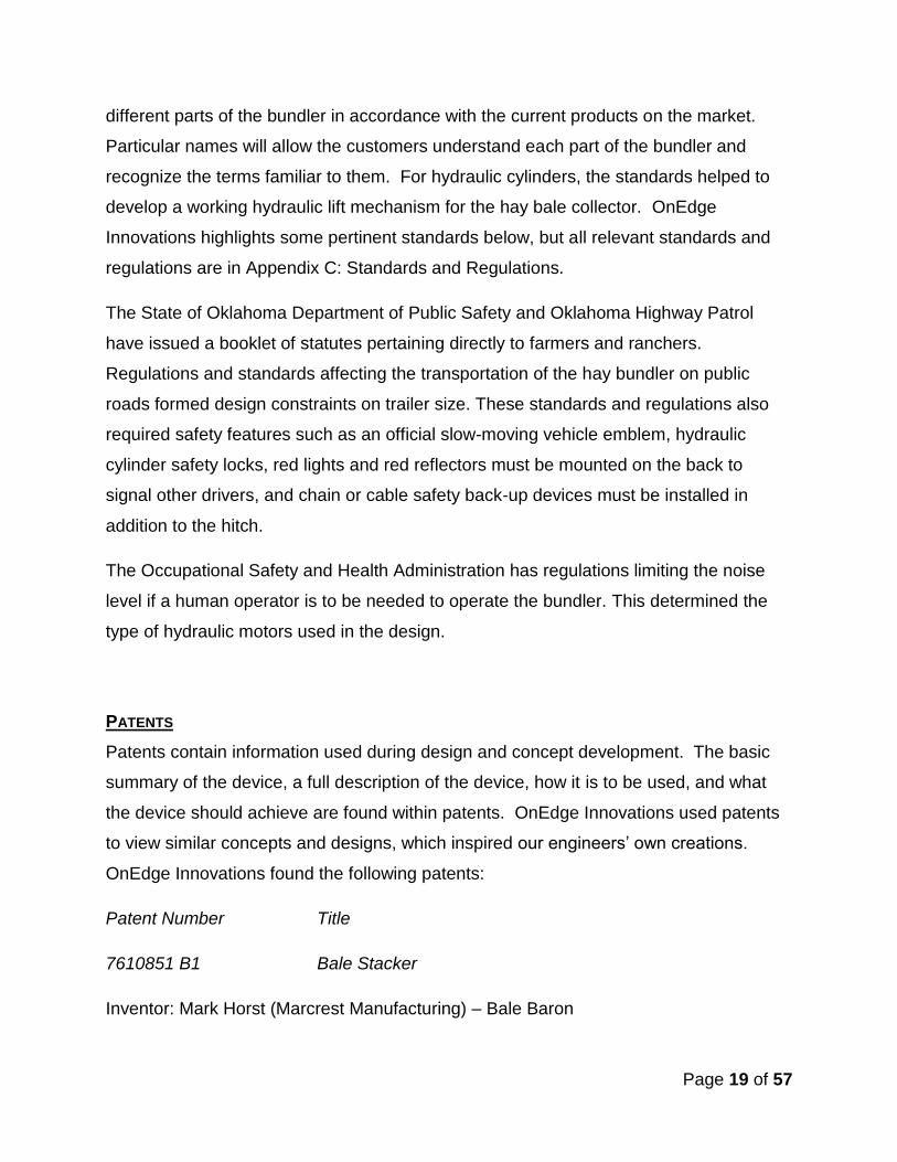
below shows the different options each competitor offers for their bundler along with the
Boxel QBer.
Table 2: Competitive Analysis
TECHNICAL ANALYSIS
The technical analysis forecasts the direction of prices through the study of past market
data, generally the price and the volume of product. The following sections contain all
relevant published information which aided in the design of the product, such as
standards and patents. This analysis also provides testing and modeling information
completed during the development of the product.
STANDARDS AND REGULATIONS
In industry, standards and regulations establish uniform engineering and technical data,
methods, processes and practices. Industry standards provide information for concept
development and aid in reforming ideas that incorporate exchangeability among design
components. The American Society of Agricultural and Biological Engineers publish
volumes of industry standards for most any agricultural application.
OnEdge Innovations found numerous standards pertaining to the current design aspect,
including terminology for hay handling equipment, standards for hydraulic cylinders and
safety requirements. The basic terminology for hay handling equipment helps name
Page 19 of 57
different parts of the bundler in accordance with the current products on the market.
Particular names will allow the customers understand each part of the bundler and
recognize the terms familiar to them. For hydraulic cylinders, the standards helped to
develop a working hydraulic lift mechanism for the hay bale collector. OnEdge
Innovations highlights some pertinent standards below, but all relevant standards and
regulations are in Appendix C: Standards and Regulations.
The State of Oklahoma Department of Public Safety and Oklahoma Highway Patrol
have issued a booklet of statutes pertaining directly to farmers and ranchers.
Regulations and standards affecting the transportation of the hay bundler on public
roads formed design constraints on trailer size. These standards and regulations also
required safety features such as an official slow-moving vehicle emblem, hydraulic
cylinder safety locks, red lights and red reflectors must be mounted on the back to
signal other drivers, and chain or cable safety back-up devices must be installed in
addition to the hitch.
The Occupational Safety and Health Administration has regulations limiting the noise
level if a human operator is to be needed to operate the bundler. This determined the
type of hydraulic motors used in the design.
PATENTS
Patents contain information used during design and concept development. The basic
summary of the device, a full description of the device, how it is to be used, and what
the device should achieve are found within patents. OnEdge Innovations used patents
to view similar concepts and designs, which inspired our engineers’ own creations.
OnEdge Innovations found the following patents:
Patent Number Title
7610851 B1 Bale Stacker
Inventor: Mark Horst (Marcrest Manufacturing) – Bale Baron

Page 20 of 57
This patent involves a method for consolidating a plurality of bales into a bale bundle.
An upstream opening brings the bales in a compression chamber. The bales are
compressed from the bottom and the front. After compression the bundle is released to
the downstream opening. This opening releases the bale back to the field13.
6397738 B1 Hay Bale Stacking and Bundling Method
Inventor: Owen J. Brown, Jr. – Bale Band-It
This patent involves a method to form a bundle of twenty-one square bales. The
apparatus will elevate the hay bale from the field, mechanically stack the hay into a
bundle, compress the hay from one side, band the hay with two metal bands, then
release the hay back into the field. The machine is computer controlled from the tractor
operator and fully automated13.
These patents were used to analyze the process used by patent holders when they
developed their products. Complete patents can be found in Appendix C: Patents.
FIELD/PHYSICAL TESTING AND DATA
Boxel Manufacturing has tested the integrity of a 10 hay bale bundle. The hay bundle
can be stacked at least three bundles high in a barn without losing integrity. A forklift
can easily move a bundle without pallets, and the bundle can be transported on a trailer.
By using testing and calculations completed with a hydraulic flow test machine (Power
Pack), supplied by the BAE Laboratory, OnEdge Innovations determined the required
hydraulic capacity. Required flow rate, pressure, hydraulic cylinder retraction and
extension speeds, as well as hydraulic motor speeds, will all be tested to find the
optimum system. **Give Results?**
Orientations of compression were tested on the 10 bale bundle to determine if 2 -
directional compression is needed or optional. Degree of compression testing coincides
with the testing of the hydraulic system.

Page 21 of 57
Different stacking and banding systems have been tested on a 10 bale bundle. OnEdge
Innovations found the best stacking method to maintain bale integrity is to stack all
bales on edge with the three in the bottom row, four in the middle and three on top. See
Figure 9 in the Hay Bale Stacking segment of this report for further stacking information.
OnEdge Innovations researched banding machines to bind the 10 bale stack. We were
interested in a bander that would automatically seal plastic strap bands. Originally, we
looked at banders that would tighten the bands automatically or have need for manually
tightening. OnEdge Innovations and Brad Lahman met with representatives of Omni-
Packaging November 19, 2010. After testing the Zapak ZP36 and the Strapex BXT-80,
OnEdge Innovations and Lahman chose to use the Zapak ZP36. More information
regarding the Zapak ZP36 can be found on in the Bundle Banding segment of this
report.
The entire machine will be field tested for timing of processes, speed and the quality of
bundle produced when the prototype is complete.
SIMULATION AND MODELING
OnEdge Innovations modeled preliminary ideas to help visualize concepts and
communicate with client fabrication specifications. We used SolidWorks to model
components and generate computer assemblies. ***Add More***
ENVIRONMENTAL AND GLOBAL IMPACTS
OnEdge Innovations took into consideration the environmental and global impacts a hay
bundler might have. Beginning with the production stage, it is important to understand
where the materials will come from and how they are manufactured.
Factors that could affect the environment consist of chemical runoff from manufacturing,
maintenance materials like oil and grease, and disposal of no-longer-useful parts or
units.

Page 22 of 57
DESIGN CRITERIA
Boxel Manufacturing required the final hay bundle design to incorporate the following
components:
1. Mobile – move through a field, not a stationary unit
2. Hay Compression
3. Banding
4. Release of the bundle back to the field
5. Use of a human operator – to keep cost low relative to fully automated systems
6. Manufacturability
7. Shade for operator comfort
CONCEPT DEVELOPMENT
OnEdge Innovations decided to divide the project into six major categories:
1. Hay bale elevation from the field
2. Hay bale stacking
3. Hay compression on the trailer
4. Automated bundle banding system
5. Bundle release to the original field location
6. Trailer framework
This allowed the design of each component to meet requirements and requests of
customers along with industry standards. A design concept was developed for each of
the categories. OnEdge Innovations adjusted these concepts to meet the design
criteria, as discussed in the following sections. **How did we adjust? (if we did)**
POTENTIAL SOLUTIONS
Trailer Framework

Page 23 of 57
The trailer framework was designed to function in the field and for safe travel down a
public road. OnEdge Innovation constrained the trailer to only be 8 feet wide to avoid
the need for “wide load” signs or signals.
The length of the trailer will be 12 feet, but could change depending on the required
dimensions of the other components of the bale bundler (i.e. compression, banding, and
releasing mechanisms).
The trailer will be made of 4” x 4” x ¼” square tubing. Bracing will be placed across the
trailer for support of the compression mechanism and the releasing apparatus.
Figure 4: Trailer Framework
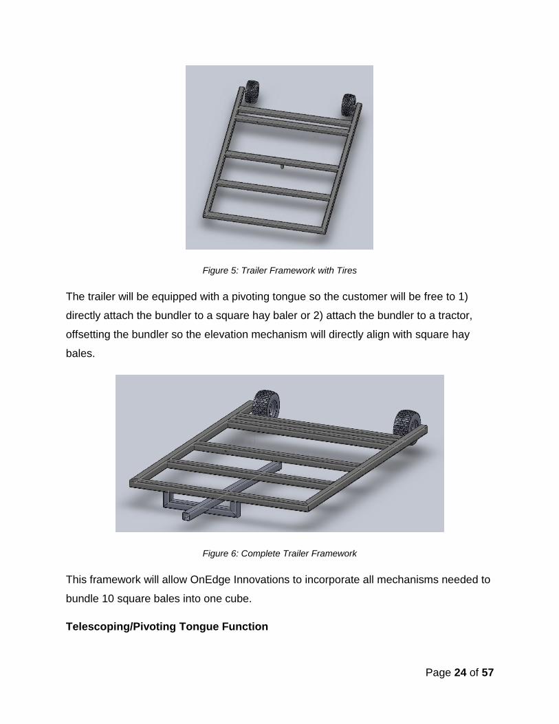
Two tires will be attached on the inside of the back of the trailer. Trailer tires will be
used. The specifications for these tires are approximately 15” x 5” white spoke 4” - 4.5”
bolt circle with 1,820 tire capacity.
Page 24 of 57
Figure 5: Trailer Framework with Tires
The trailer will be equipped with a pivoting tongue so the customer will be free to 1)
directly attach the bundler to a square hay baler or 2) attach the bundler to a tractor,
offsetting the bundler so the elevation mechanism will directly align with square hay
bales.
Figure 6: Complete Trailer Framework
This framework will allow OnEdge Innovations to incorporate all mechanisms needed to
bundle 10 square bales into one cube.
Telescoping/Pivoting Tongue Function

Page 25 of 57
OnEdge Innovations decided to incorporate a telescoping function into the pull tongue
design. This will allow the trailer to attach to any baler or trator. As seen from the
included picture, the tongue will have the ability to pivot left and right a limited amount of
degrees as well as telescope in and out a limited amount of distance. Ultimately, the
design will allow an infinite number of positions available to the bundler within the given
boundaries. The operator can set the location of the bundler behind both the tractor
and the hay baler. The swinging function is critical to the elevating portion of the design
because it allows the bundler to swing from behind the tractor to an offset position
allowing elevating table to be let down and operated. The telescoping function of the
tongue will allow the bundler to hook to the back of the hay baler in the correct location
for the elevating table to be hooked directly to the bale exit chamber of the hay baler.
Figure 7: Trailer Frame and Telescoping, Pivoting Tongue
Hay Bale Elevation
Page 26 of 57
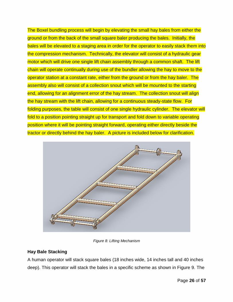
The Boxel bundling process will begin by elevating the small hay bales from either the
ground or from the back of the small square baler producing the bales. Initially, the
bales will be elevated to a staging area in order for the operator to easily stack them into
the compression mechanism. Technically, the elevator will consist of a hydraulic gear
motor which will drive one single lift chain assembly through a common shaft. The lift
chain will operate continually during use of the bundler allowing the hay to move to the
operator station at a constant rate, either from the ground or from the hay baler. The
assembly also will consist of a collection snout which will be mounted to the starting
end, allowing for an alignment error of the hay stream. The collection snout will align
the hay stream with the lift chain, allowing for a continuous steady-state flow. For
folding purposes, the table will consist of one single hydraulic cylinder. The elevator will
fold to a position pointing straight up for transport and fold down to variable operating
position where it will be pointing straight forward, operating either directly beside the
tractor or directly behind the hay baler. A picture is included below for clarification.
Figure 8: Lifting Mechanism
Hay Bale Stacking
A human operator will stack square bales (18 inches wide, 14 inches tall and 40 inches
deep). This operator will stack the bales in a specific scheme as shown in Figure 9. The

Page 27 of 57
starting bundle dimensions are approximately 50 inches tall, 54-58 inches wide, and 40
inches deep. After compression, the approximate dimensions are 46 inches tall, 48
inches wide and 40 inches deep. These dimensions were provided by Boxel after
testing design concepts with a prototype. **Field Testing Data**
Figure 9: Bale Stacking Scheme
This stacking scheme creates optimum storing or transporting of the bundle in a
standard semi-truck trailer (100 inches) (14), a standard pallet (4 feet by 4 feet) (15) and
setting the cube in the back of a customer’s full size truck (62.4 inches) (16) after
purchase. This stacking scheme makes the bundles ideal for stacking on top of each
other in a hay storing facility. The staggered edges in the middle increase the integrity of
the bale after banding.
Hay Compression
The compression system will be formed from two walls: one stationary and one
dynamic. The walls will be made of 2” x 2” x ¼” square tubing and 16 gauge sheet
metal. Both walls are 42 inches wide, 62 inches tall, and 8 inches deep. The dimensions
were determined from the dimensions of the 10 hay bale bundle.
Page 28 of 57
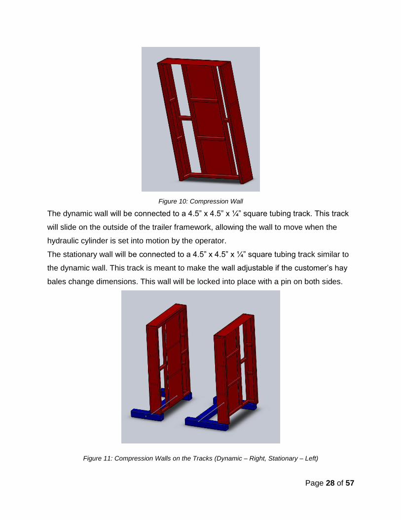
Figure 10: Compression Wall
The dynamic wall will be connected to a 4.5” x 4.5” x ¼” square tubing track. This track
will slide on the outside of the trailer framework, allowing the wall to move when the
hydraulic cylinder is set into motion by the operator.
The stationary wall will be connected to a 4.5” x 4.5” x ¼” square tubing track similar to
the dynamic wall. This track is meant to make the wall adjustable if the customer’s hay
bales change dimensions. This wall will be locked into place with a pin on both sides.
Figure 11: Compression Walls on the Tracks (Dynamic – Right, Stationary – Left)
Page 29 of 57
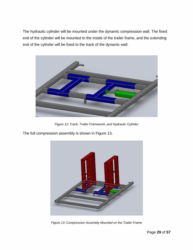
The hydraulic cylinder will be mounted under the dynamic compression wall. The fixed
end of the cylinder will be mounted to the inside of the trailer frame, and the extending
end of the cylinder will be fixed to the track of the dynamic wall.
Figure 12: Track, Trailer Framework, and Hydraulic Cylinder
The full compression assembly is shown in Figure 13.
Figure 13: Compression Assembly Mounted on the Trailer Frame
Page 30 of 57
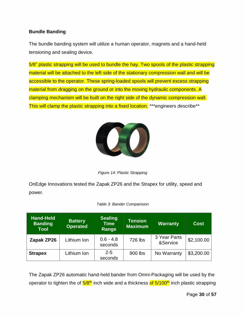
Bundle Banding
The bundle banding system will utilize a human operator, magnets and a hand-held
tensioning and sealing device.
5/8” plastic strapping will be used to bundle the hay. Two spools of the plastic strapping
material will be attached to the left side of the stationary compression wall and will be
accessible to the operator. These spring-loaded spools will prevent excess strapping
material from dragging on the ground or into the moving hydraulic components. A
clamping mechanism will be built on the right side of the dynamic compression wall.
This will clamp the plastic strapping into a fixed location. ***engineers describe**
Figure 14: Plastic Strapping
OnEdge Innovations tested the Zapak ZP26 and the Strapex for utility, speed and
power.
Table 3: Bander Comparision
Hand-Held Banding
Tool
Battery Operated
Sealing Time
Range
Tension Maximum
Warranty Cost
Zapak ZP26 Lithium Ion 0.6 - 4.8 seconds
726 lbs 3 Year Parts
&Service $2,100.00
Strapex Lithium Ion 2-5 seconds
900 lbs No Warranty $3,200.00
The Zapak ZP26 automatic hand-held bander from Omni-Packaging will be used by the
operator to tighten the of 5/8th inch wide and a thickness of 5/100th inch plastic strapping

Page 31 of 57
around the hay bundle and seal the straps together. The sealing time of the Zapak
ZP26 is two seconds. This ZP26 is battery operated so cords will not be a safety issue.
Zapak ZP26
In order to get the plastic bands completely around the entire hay bundle, the machine
utilizes a vertical rack and pinion system with protruding bars. A hydraulic motor
controlled by the operator will operate the system.
Figure 15: Banding System
Before the operator stacks the hay into the specific hay scheme, he/she will pull both
bands from the spools on the left, under both of the protruding bars, then clamp the
ends into the clamping mechanism on the right side. The operator will then engage the
hydraulic motor, moving the straps down to the bottom of the hay stacking platform.
Since the spools of plastic are spring-loaded, they will not recoil; therefore, the banding

Page 32 of 57
system can be moved back up into its resting position. The operator will begin stacking
the individual square bales into the machine, on top of the two bands. After stacking and
compression is complete, the operator will cut the left side of the straps. The ends of the
straps will then be tightened and sealed by the operator with the hand-held bander.
Compression will be released, and the banding of the bundle is complete.
Bundle Release
The bundle release apparatus will relocate the hay bundle from the trailer to the field.
This mechanism will also act as the hay stacking platform.
The frame will be made of 2” x 2” x ¼” square tubing and 16 gauge sheet metal. The
dimensions are 68 inches tall, 39 inches wide, and the bottom platform extends 36
inches from the back support. The supports for the releasing system are the same
supports for the banding system which will save space and materials. This support is
made of 4” x 4” x ¼” square tubing and stands at 65 inches tall.
Figure 16: Releasing System – Resting Position
A hydraulic cylinder will be used to flip the platform approximately 120°, sliding the
bundle of hay into the field. The extending end of the cylinder will be attached just below
the pivot point of the platform, and the fixed point will be attached to a framework on the
back of the trailer.
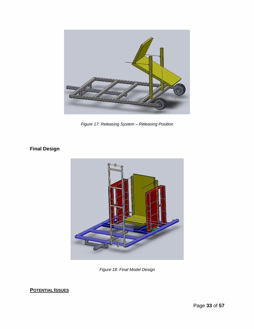
Page 33 of 57
Figure 17: Releasing System – Releasing Position
Final Design
Figure 18: Final Model Design
POTENTIAL ISSUES

Page 34 of 57
The design has many different hydraulic functions, some continuous. Depending on the
size of the tractor hydraulic fluid reservoir, heat could build up in the hydraulic
components. The excess heat will affect both safety and performance of the equipment.
If heat does become an issue, OnEdge Innovations will utilize a satellite reservoir and/or
an air to oil cooler designed into the bundler itself. It will not be an add-on to the tractor.
With the amount of force required to compress the hay bales, and the force required to
flip the hay into the field by the releasing mechanism, structural integrity was a potential
issue. OnEdge Innovations planned to reinforce the framework of said components if
needed.
Debris could affect the performance of the hydraulic components if not properly
cleaned. OnEdge Innovations recommends blowing out the components with an air
compressor after every use.
SOLUTION ANALYSIS
Hydraulics will be modeled using Hydraulic Automation Studio software. This software
simulates cylinder movement, flow lines, heat dissipated and motor movements. It was
instrumental in modeling different hydraulic functions and issues.
Engineering calculations and stress analysis models aided in resolving structural
integrity issues. This analysis will determine the best component combinations while
meeting all specifications and requirements.
TRACTOR REQUIREMENTS
See Appendix G
HYDRAULIC COMPONENTS / CALCULATIONS
See Appendix H

Page 35 of 57
PROPOSED MEDIA / COMMUNICATIONS PLAN
OnEdge Innovations will promote the final product created through means of paper
publications, Internet sites and trade shows prominent in Oklahoma and northern
Texas.
OnEdge Innovations created a video of the QBer in action. A link to the video can be
found on Boxel’s website www.varguardstoragemodules.com. This allows potential
customers to view the QBer and its actions at a low cost for Boxel. Additionally, OnEdge
Innovations has designed advertisements for Boxel to place in magazines circulating to
hay producers. Hay and Forage Grower, Fastline and High Plains Journal are potential
magazines to contact about advertising space. The High Plains Journal produces a
monthly publication strictly for new products. OnEdge Innovations has also created
brochures exemplifying the characteristics of the QBer. While attending many of the
trade shows in Oklahoma and northern Texas, brochures can be distributed to hay
producers.
*insert cost table*
PROPOSED BUSINESS PLAN / FINANCIAL ANALYSIS
In the current stages of the economy, individuals must find methods of production that
can satisfy needs, maximizes profits and produce at a price level meeting firms’ budget
capabilities. Our client Brad Lahman, owner and operator of Boxel Manufacturing,
currently makes show boxes and feeders for today’s youth and agriculturists. As a
professional custom hay harvest, Lahman envisions an innovative bale bundler with the
ability to bale 10 small square bales into one bundle. Hay producers will experience a
cheaper, well-made bale compressing accumulator 80% cheaper than the accumulator
models currently in the market. A 10 bale bundle will be easily moved, decreasing
transportation time from the field to the barn. This decrease will lower the high labor
inputs of loading, transporting and stacking square bales, making relocation and
unloading easier than that of the 21 bale bundle.
Boxel Manufacturing’s QBer is suited for individuals entering into custom hay harvesting
markets who might not have the cash flow to meet prices of other bale bundlers in the

Page 36 of 57
market place. This product’s price falls under a smaller farm’s budget constraint,
including hobby farms.
OnEdge Innovations created a safe, dependable product available to small farmers.
Boxel originally set a maximum manufacturing cost of $6000. The final production cost
of the QBer is $*****. The original expected retail price of the QBer was $16,000. Boxel
will set an asking price of $****
PROJECT SCHEDULE
Complete Work Breakdown Schedule and Tasks can be found in Appendix A
The following seven pages include the Gantt Chart for the project.
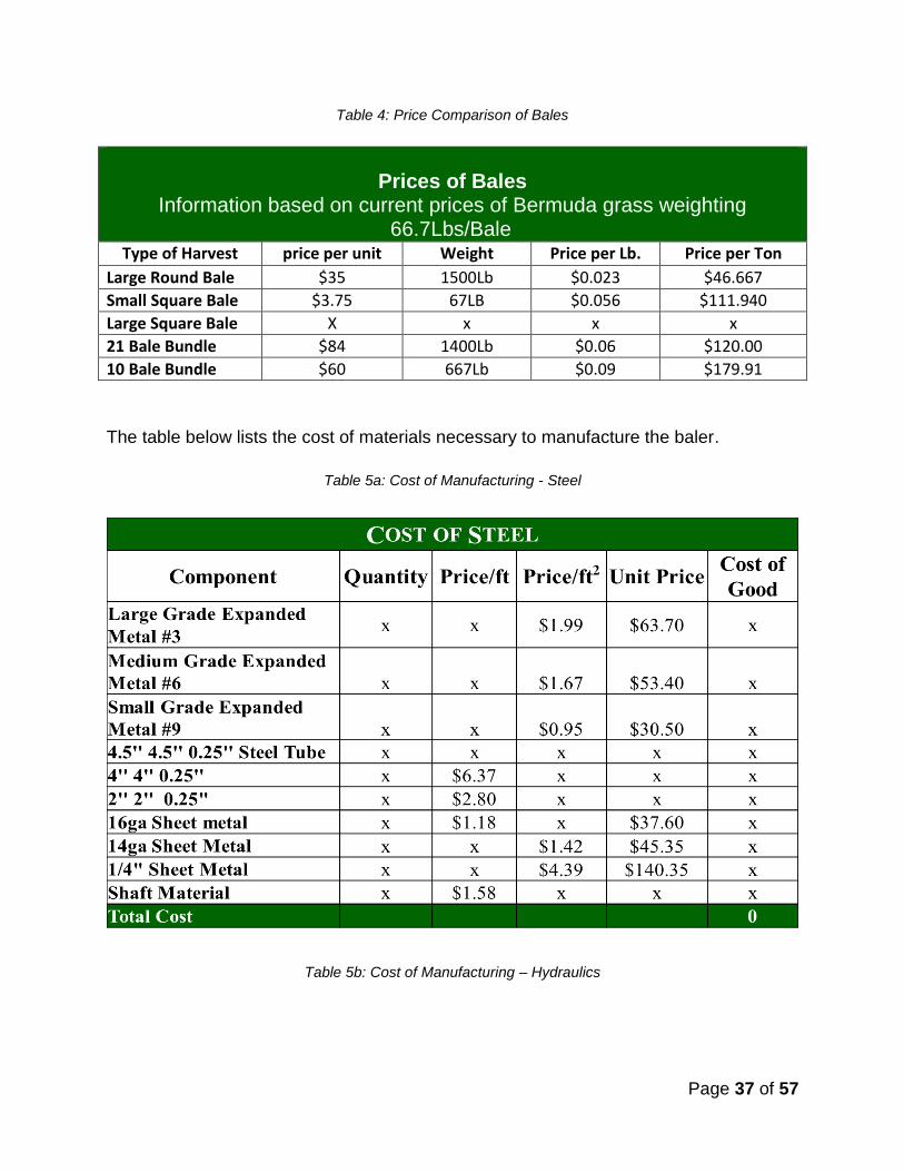
COST ANALYSIS
The graph below demonstrates the different ways to bale Bermuda grass and the price
that relates to the method12.
Page 37 of 57
Table 4: Price Comparison of Bales
Prices of Bales Information based on current prices of Bermuda grass weighting
66.7Lbs/Bale
Type of Harvest price per unit Weight Price per Lb. Price per Ton
Large Round Bale $35 1500Lb $0.023 $46.667
Small Square Bale $3.75 67LB $0.056 $111.940
Large Square Bale X x x x
21 Bale Bundle $84 1400Lb $0.06 $120.00
10 Bale Bundle $60 667Lb $0.09 $179.91
The table below lists the cost of materials necessary to manufacture the baler.
Table 5a: Cost of Manufacturing - Steel
Table 5b: Cost of Manufacturing – Hydraulics
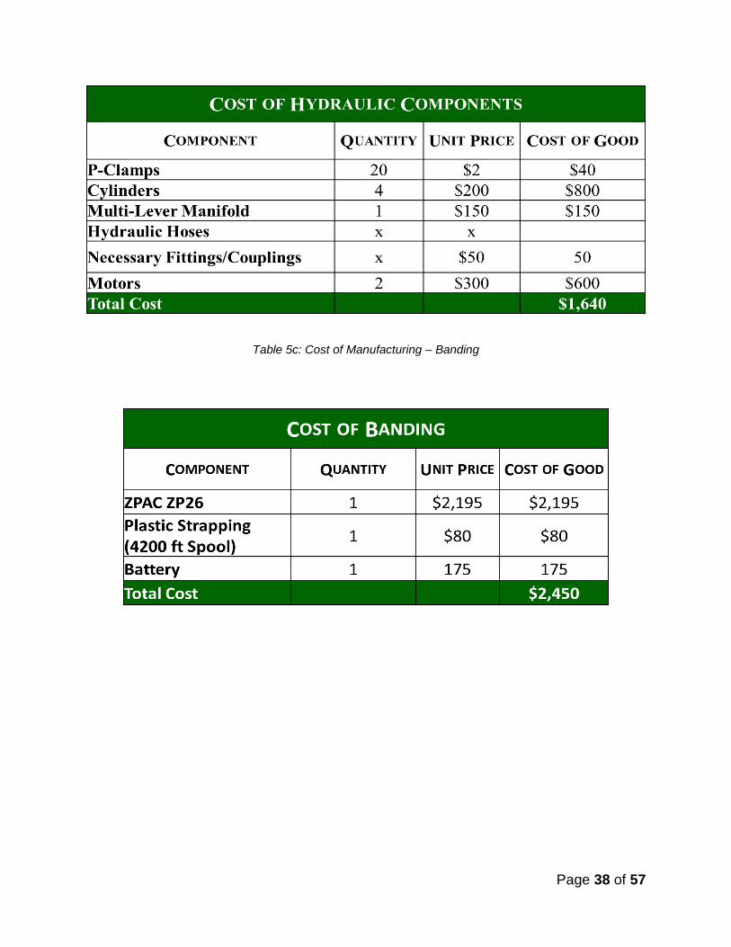
Page 38 of 57
Table 5c: Cost of Manufacturing – Banding

Page 39 of 57
Table 5d: Cost of Manufacturing – Miscellaneous
Table 5e: Manufacturing Costs – Estimated Total
Estimated Total Cost
Component Subtotals
Steel ~$2,500
Hydraulics $1,640
Banding $2,450
Miscellaneous $778.12
Total Cost $7,448.12
CONCLUSION

Page 40 of 57
OnEdge Innovations created a new product for Boxel Manufacturing to help expand its
business in the hay implement market. The QBer will be competitive in the market,
scalable and functional. OnEdge Innovations used the information gathered in the Fall
Report, including market research, patent search, industry standards and our own
ideas, to develop a design meeting all goals. Our final product passed field testing and,
as shown in our economic research, will increase hay producers’ profits.

Page 41 of 57
SOURCE CITED
1) Cusato-Wood, Robin, Sanders, Greg, Smotherman, Kinley, Whitney, Lisa. National
Hay, Feed & Seed Weekly Summary. USDA. Vol. 13, No. 11-01. Nov. 5, 2010.
Accessed Nov. 7, 2010.
2) God, Family, & Country. Bale Bandit. www.balebandit.com/BanditInfo.htm. Accessed
Oct. 16, 2010.
3) Marcrest Manufacturing Inc. Bale Baron. http://www.balebaron.com/Specifications.html
Accessed Oct. 16, 2010.
4) IBISWorld. Horse and Other Equine Production in US. Report 11292. Aug. 2010.
Accessed Nov. 10, 2010.
5) Brus, Brian. Super Barn to defend Okla.’s equine industry. The Oklahoma City
Journal Record. June 20, 2007. Accessed Nov. 10, 2010.
6) Agri Marketing. Ag/Rural Show Guide. Farm Progress Magazine Group. Accessed
Nov. 13, 2010.
7) Oklahoma State Fair. October Signaled the Beginning of the Fall Horse Show
Season. Oklahoma State Fair News Release. Nov. 16, 2009. Accessed Nov. 11,
2010.
9) Boyles, Stephen. Feeding the Show Steer. Date published unavailable. Accessed
Nov. 13, 2010.
10) Oklahoma Show Scene. Show Calendar. 2010. Accessed Nov. 13, 2010.
11) Oklahoma State Fair. Livestock information 2010. Accessed Nov. 13, 2010.
12) Personal Communication. Brad Lahman. 14 November 2010.
13) Brown, Owen J., “Hay Bale Stacking and Bundling Method.” Patent 6397738 B1.
04 June 2002.

Page 42 of 57
14) National Semi Corporation. 2010. http://www.nationalsemi.com/semi-
trailers/53ARN2.pdf. Accessed 14
15) Allied Pallet Company. 2007. http://www.alliedpallet.net/Information.htm. Accessed
14 November 2010.
16) General Motors Company. 2010.
http://www.gmc.com/sierra/1500/specsDimension.jsp. Accessed 14 November 2010
17) Omni Packing. 2010. http://omnipackaging.shoppkg.com/shop/C1951.aspx.
Accessed 14 November 2010

Page 43 of 57
APPENDIX A: WORK BREAKDOWN SCHEDULE
Initial Research 7.1. Research Boxel Manufacturing
7.1.1. Determine who they are
7.1.2. Determine what they do
7.1.3. Determine what their resources are
7.1.3.1. Determine Boxel’s supplier(s)
7.2. Research Industry
7.2.1. Determine industry size
7.2.2. Determine market size
7.3. Research Competitors
7.3.1. Research Competitor Resources
7.3.2. Research Competitor Products
7.3.2.1. Determine their products
7.3.2.2. Identify what is unique to their product
7.3.2.2.1. Determine what is good about the competitors’ products
7.3.2.2.2. Determine what is bad about the competitors’ products
7.3.2.3. Determine competitors prices
7.4. Research Dealers
7.5. Research Customers
7.5.1. Identify customers’ need
7.5.2. Learn what they like about existing hay bundlers
7.5.3. Learn what they don’t like about existing hay bundlers
7.6. Research Technical Sources
7.6.1. Research Standards
7.6.1.1. Research ASABE standards
Page 44 of 57
7.6.2. Research Patents
8. Develop Rough Budget
8.1. Review Initial Research
8.2. Created Budget
8.3. Submit to senior design professors for review
9. Develop Design
9.1. Develop an hay pick-up concept
9.1.1. Review Initial Research
9.1.1.1. Look at previous patents
9.1.1.2. Look at previous standards
9.1.1.3. Look at competitor products
9.1.2. Draw final concepts in SolidWorks
9.2. Develop a hay compression concept
9.2.1. Review Initial Research
9.2.1.1. Look at previous patents
9.2.1.2. Look at previous standards
9.2.1.3. Look at competitor products
9.2.2. Look at hay bundle dimensions to decide on compression specifications
9.2.3. Drew final concepts in SolidWorks
9.3. Develop a bale banding concept
9.3.1. Research different types of banding material
9.3.2. Research different types of hand-held banders
9.3.3. Review Initial Research
9.3.3.1. Look at previous patents
9.3.3.2. Look at previous standards
9.3.3.3. Look at competitor products

Page 45 of 57
9.3.4. Looked at geometry of bundle to find length of material per bale to design mechanism to get band around the bale
9.3.5. Drew final concepts in SolidWorks
9.4. Develop a bundle release mechanism
9.4.1. Research different types of release systems
9.4.2. Review Initial Research
9.4.2.1. Look at previous patents
9.4.2.2. Look at previous standards
9.4.2.3. Look at competitor products
9.4.3. Drew up final concepts in SolidWorks
9.5. Calculations/Testing
9.5.1. Calculate hay compression force requirements
9.5.2. Calculate hydraulic flow requirements needed for each (3 total) hydraulic cylinder and the hydraulic motor.
9.5.3. Test the hand-held bander’s seal integrity
9.5.4. Miscellaneous calculations (on all other necessary components)
9.6. Finalize Design
9.6.1. Decide on final hay pick-up concept
9.6.2. Decide on final hay compression concept
9.6.3. Decide on final bale banding concept
9.6.4. Decide on final bundle release system
9.6.5. Create a full assembly of all parts
9.6.6. Create a presentation of all work completed
9.6.7. Present to Boxel, Faculty and Peers

Page 46 of 57
---------------------------------------------- Spring 2011 Semester -----------------------------------
10. Build Prototype
10.1. Create Construction Drawings for each part
10.1.1. Create drawings in SolidWorks
10.1.2. Include all initial dimensions
10.2. Decide where to build machine
10.2.1. Frame and larger fabrication – Boxel
10.2.2. Small, detailed fabrication – OSU BAE Lab and Shop
10.3. Order parts through Boxel purchasing
10.4. Construct Prototype
10.4.1. Cut steel bars, rods, angles, etc. to desired sizes for framework and other parts
10.4.2. Drill holes in steel for various parts
10.4.3. Join/Weld the framework together
10.4.4. Attach (fasten or weld) the other components (compression, pick-up, banding, release mechanisms)
10.4.5. Attach the axles/wheels
10.4.6. Construct and attach the hitch system
10.4.7. Attach hydraulic components: cylinders, values, manifold, hoses, motor
11. Prototype Testing
11.1. Run tests on all components
11.1.1. Dr. Dan Storm loan 10 bales of hay for testing
11.1.2. Hook implement to tractor
11.1.3. Run implement as would in field conditions – laying 10 bales out in a row and testing all mechanisms and components

Page 47 of 57
11.2. Review Prototype Design
11.2.1. Make any necessary changes to design that come up in testing
11.3. Review Construction Drawings
11.3.1. Make any necessary changes to dimensions that come up in testing
11.4. Repeat
12. Market Product
12.1. Develop a Business Plan
12.2. Develop Marketing Ideas
12.2.1. Create brochure for product
12.2.2. Add product information to Boxel Web site
13. Present Final Design with Prototype and Marketing Materials to Boxel Manufacturing
13.1. Create a Presentation
13.2. Present prototype, marketing materials, and business plan to Boxel, Faculty, and Peers
Page 48 of 57
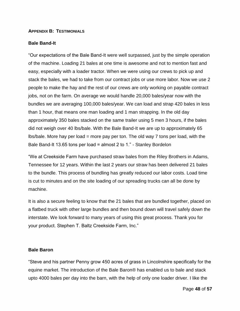
APPENDIX B: TESTIMONIALS
Bale Band-It
“Our expectations of the Bale Band-It were well surpassed, just by the simple operation
of the machine. Loading 21 bales at one time is awesome and not to mention fast and
easy, especially with a loader tractor. When we were using our crews to pick up and
stack the bales, we had to take from our contract jobs or use more labor. Now we use 2
people to make the hay and the rest of our crews are only working on payable contract
jobs, not on the farm. On average we would handle 20,000 bales/year now with the
bundles we are averaging 100,000 bales/year. We can load and strap 420 bales in less
than 1 hour, that means one man loading and 1 man strapping. In the old day
approximately 350 bales stacked on the same trailer using 5 men 3 hours, if the bales
did not weigh over 40 lbs/bale. With the Bale Band-It we are up to approximately 65
lbs/bale. More hay per load = more pay per ton. The old way 7 tons per load, with the
Bale Band-It 13.65 tons per load = almost 2 to 1.” - Stanley Bordelon
“We at Creekside Farm have purchased straw bales from the Riley Brothers in Adams,
Tennessee for 12 years. Within the last 2 years our straw has been delivered 21 bales
to the bundle. This process of bundling has greatly reduced our labor costs. Load time
is cut to minutes and on the site loading of our spreading trucks can all be done by
machine.
It is also a secure feeling to know that the 21 bales that are bundled together, placed on
a flatbed truck with other large bundles and then bound down will travel safely down the
interstate. We look forward to many years of using this great process. Thank you for
your product. Stephen T. Baltz Creekside Farm, Inc.”
Bale Baron
“Steve and his partner Penny grow 450 acres of grass in Lincolnshire specifically for the
equine market. The introduction of the Bale Baron® has enabled us to bale and stack
upto 4000 bales per day into the barn, with the help of only one loader driver. I like the

Page 49 of 57
Bale Baron® for it's simplicity, with minimal moving parts and the proven double knot
system of the Hesston knotters, identical to our own big baler. The Bale Baron® works
quickly and does not hinder our Welger 830 baler. Moving bales from the field is always
a slow process, not with the Bale Baron®, trailers are loaded with 500/600 bales in
approx half an hour. With a slight modification The Bale Baron® will tie packs of twelve,
this is a great advantage to our small bale haylage business as we can wrap packs of
twelve quickly and then wrap them as individuals when time allows. This season we
baled 35,000 hay bales and approx 8000 straw, in 2011 we aim to bale 60/70,000 hay
and 10,000 straw. Lorries were previously loaded by hand, not any more, packs are
loaded easily by teleporter, the only time we handle the bales is when we deliver to
customers unless of course they have a machine!!!”
“Convinced I needed to tap into the premium small bale equine market I was converted
to small bale packing 5 years ago. I ran a Bale Bandit in the first year but could not
achieve the capacity I required and therefore purchased a second Bale Bandit.
I continued for two years and eventually purchased an Arcusin Bale Packer to try to
solve the problem of putting through the desired quantity of bales. I still found myself
struggling and in desperation started to convert my customers over to big bales until I
was introduced to the Bale Baron. Bale Baron UK convinced me that the Bale Baron®
would meet the capacity and reliability that I needed.
In the first year I have baled over 42,000 bales and couldn't have been more impressed
with the Bale Baron and I am convinced that in a normal yielding year I could have
easily baled the 60,000-70,000 bales that I am looking for. On top of all the other
benefits of the Bale Baron® I have been able to use up my big bale twine left over from
last year!”
Arcusin Multipack B-14
No Testimonials found
Page 50 of 57
APPENDIX C: STANDARDS AND REGULATIONS

Page 51 of 57
APPENDIX D: PATENTS

Page 52 of 57
APPENDIX E: PURCHASED PRODUCTS INFORMATION

Page 53 of 57
APPENDIX F: HYDRAULIC COMPONENTS INFORMATION

Page 54 of 57
APPENDIX G: DESIGN CONSTRAINTS
Page 55 of 57
APPENDIX H: HYDRAULIC EQUATIONS

Page 56 of 57
APPENDIX I: PROTOTYPE PICTURES
Page 57 of 57
APPENDIX J: OUTSIDE COMPANY CONSULTING


![Christopher Kelly Senior Thesis Design Proposal · 2010-12-10 · Christopher Kelly Senior Thesis Design Proposal Final Report [Fall 2010] Analysis SALK HALL ADDITION The University](https://static.fdocuments.us/doc/165x107/5e9114fda9311f30b05dc2b1/christopher-kelly-senior-thesis-design-2010-12-10-christopher-kelly-senior-thesis.jpg)


