Fall 2007 L15: Combinational Circuits Lecture 15: Combinational Circuits Complete logic functions...
34
Fall 2007 L15: Combinational Circuits Lecture 15: Combinational Circuits • Complete logic functions • Some combinational logic functions – Half adders – Adders – Multiplexers – Decoders – Parity generators • Signal propagation in combinational logic • ALUs
-
date post
20-Dec-2015 -
Category
Documents
-
view
239 -
download
3
Transcript of Fall 2007 L15: Combinational Circuits Lecture 15: Combinational Circuits Complete logic functions...
Fall 2007L15: Combinational Circuits
Lecture 15: Combinational Circuits
• Complete logic functions
• Some combinational logic functions– Half adders– Adders– Multiplexers– Decoders– Parity generators
• Signal propagation in combinational logic• ALUs
Fall 2007L15: Combinational Circuits
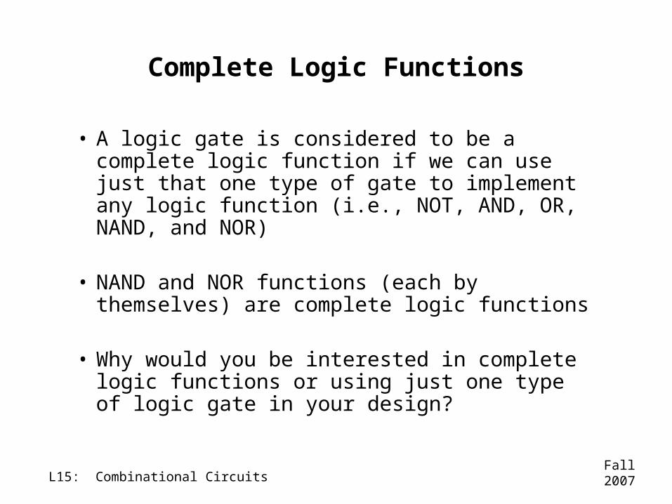
Complete Logic Functions
• A logic gate is considered to be a complete logic function if we can use just that one type of gate to implement any logic function (i.e., NOT, AND, OR, NAND, and NOR)
• NAND and NOR functions (each by themselves) are complete logic functions
• Why would you be interested in complete logic functions or using just one type of logic gate in your design?
Fall 2007L15: Combinational Circuits
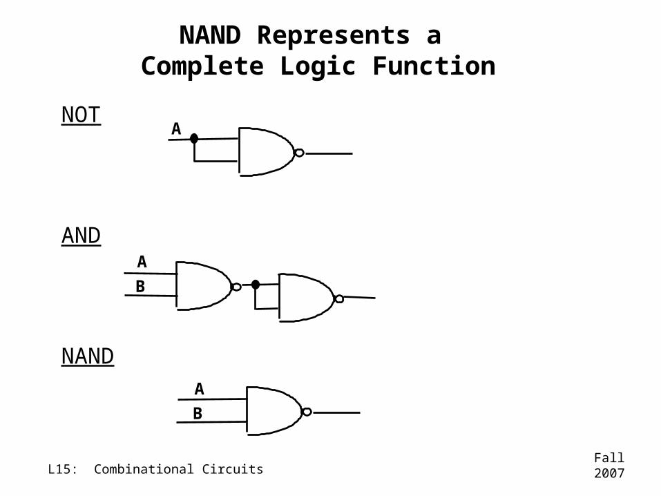
NOT
AND
NAND
NAND Represents a Complete Logic Function
A
A
B
A
B
Fall 2007L15: Combinational Circuits
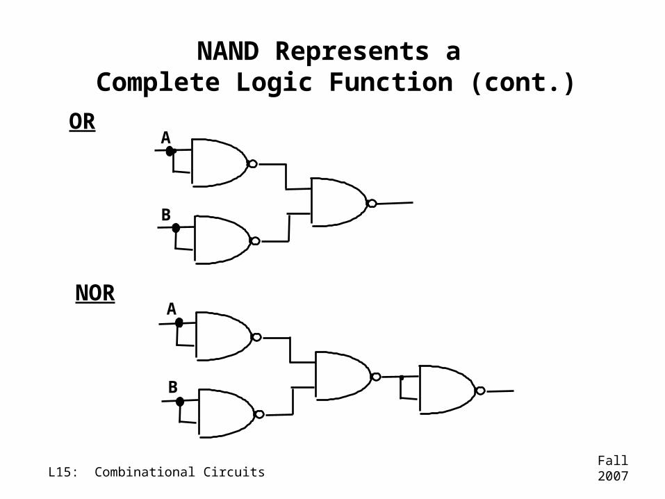
NAND Represents a Complete Logic Function (cont.)
OR
NOR
A
B
A
B
Fall 2007L15: Combinational Circuits
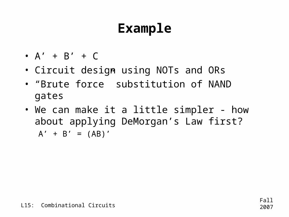
Example
• A’ + B’ + C• Circuit design using NOTs and ORs• “Brute force” substitution of NAND gates
• We can make it a little simpler - how about applying DeMorgan’s Law first? A’ + B’ = (AB)’
Fall 2007L15: Combinational Circuits
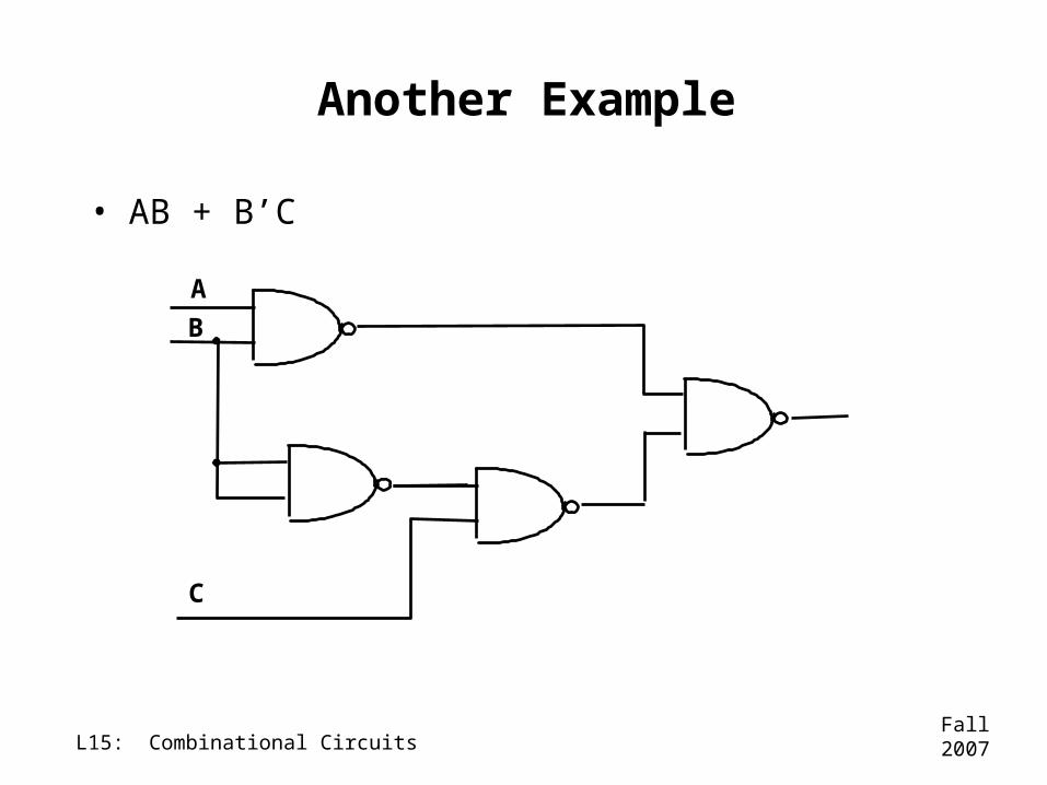
Another Example
• AB + B’C
A
B
C
Fall 2007L15: Combinational Circuits
Combinational Logic and Digital Devices
• Now that we’ve learned how to implement a logic expression in a logic-gate-level design, we can start putting those functions together to form more complex (and useful!) functions
• Digital logic that is designed so that the outputs are dependent only upon the current set of inputs is called COMBINATIONAL LOGIC
Fall 2007L15: Combinational Circuits
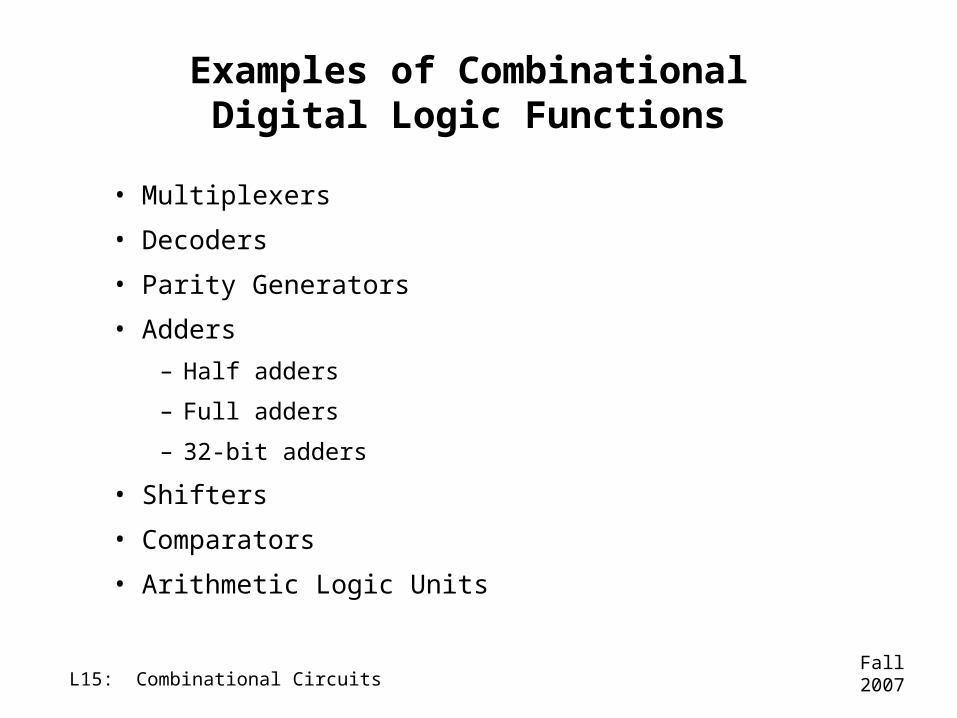
Examples of Combinational Digital Logic Functions
• Multiplexers
• Decoders
• Parity Generators
• Adders
– Half adders
– Full adders
– 32-bit adders
• Shifters
• Comparators
• Arithmetic Logic Units
Fall 2007L15: Combinational Circuits
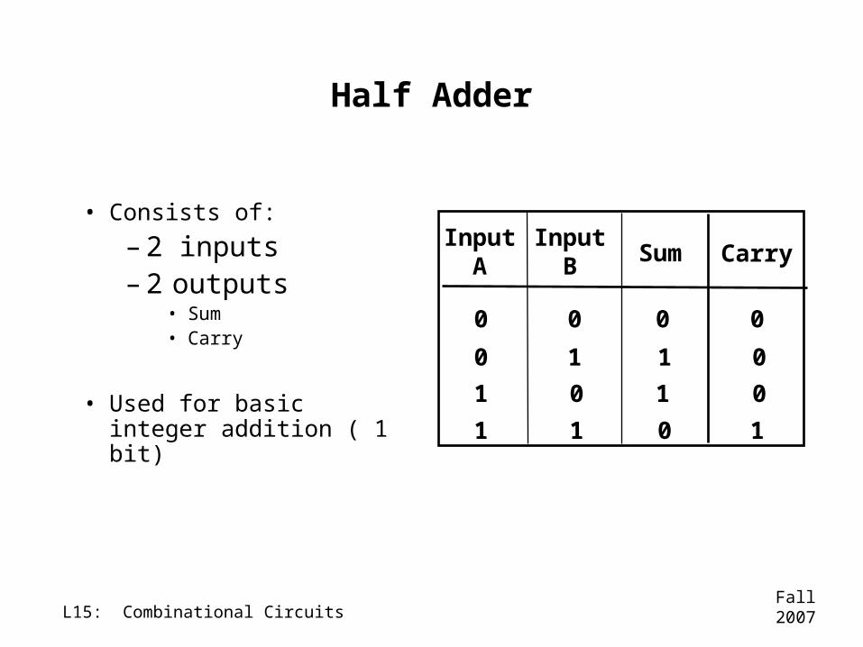
Half Adder
• Consists of:
–2 inputs–2 outputs
• Sum• Carry
• Used for basic integer addition ( 1 bit)
InputA Carry
0 0
1
1
InputB
0
0
0
0
10
01
Sum
0
1
1
1
Fall 2007L15: Combinational Circuits
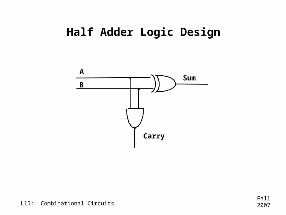
Half Adder Logic Design
A
BSum
Carry
Fall 2007L15: Combinational Circuits
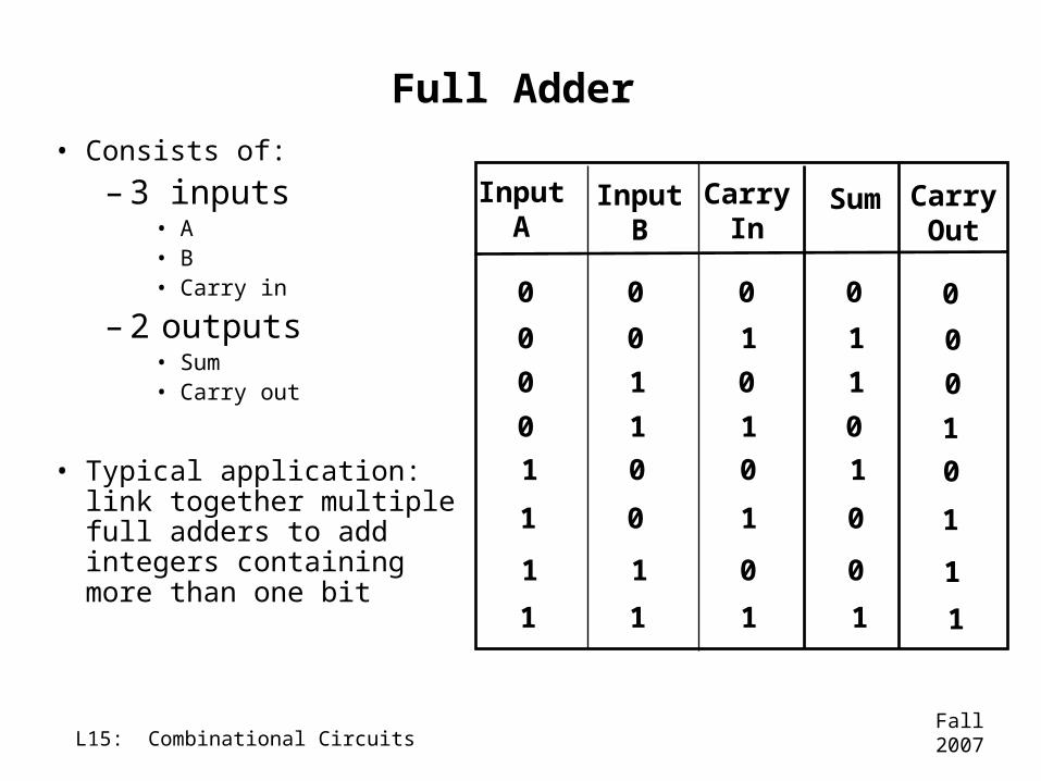
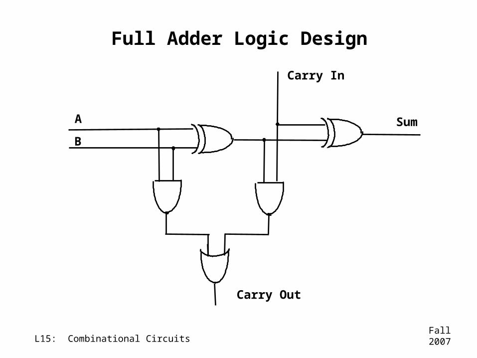
Full Adder• Consists of:
–3 inputs• A• B• Carry in
–2 outputs • Sum• Carry out
• Typical application: link together multiple full adders to add integers containing more than one bit
InputA
Sum
0 0
0
1
InputB
0
1
1
0
01
11
CarryIn
0
0
0
0
1
1
1
1
1
1
1 1
0 0
0
0
0
0
1
1
CarryOut
0
0
0
1
1
1
0
1
Fall 2007L15: Combinational Circuits
Full Adder Logic Design
A
B
Sum
Carry Out
Carry In
Fall 2007L15: Combinational Circuits
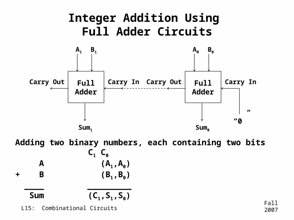
Integer Addition Using Full Adder Circuits
FullAdder
A1 B1
Sum1
Carry Out Carry In FullAdder
A0 B0
Sum0
Carry Out Carry In
“0”
Adding two binary numbers, each containing two bits C1 C0
A (A1,A0)+ B (B1,B0)____ _________Sum (C1,S1,S0)
Fall 2007L15: Combinational Circuits
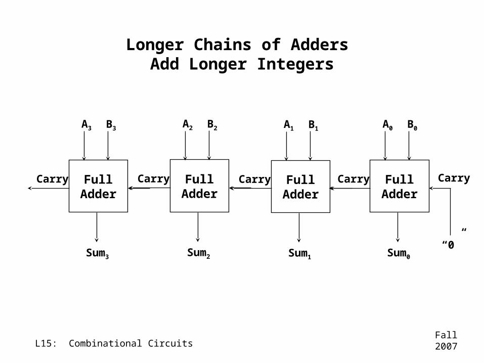
Longer Chains of Adders Add Longer Integers
FullAdder
A3 B3
Sum3
Carry FullAdder
A2 B2
Sum2
Carry FullAdder
A1 B1
Sum1
Carry FullAdder
A0 B0
Sum0
Carry Carry
“0”
Fall 2007L15: Combinational Circuits
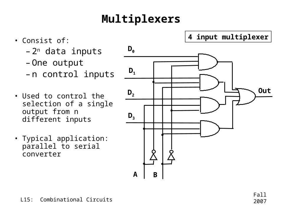
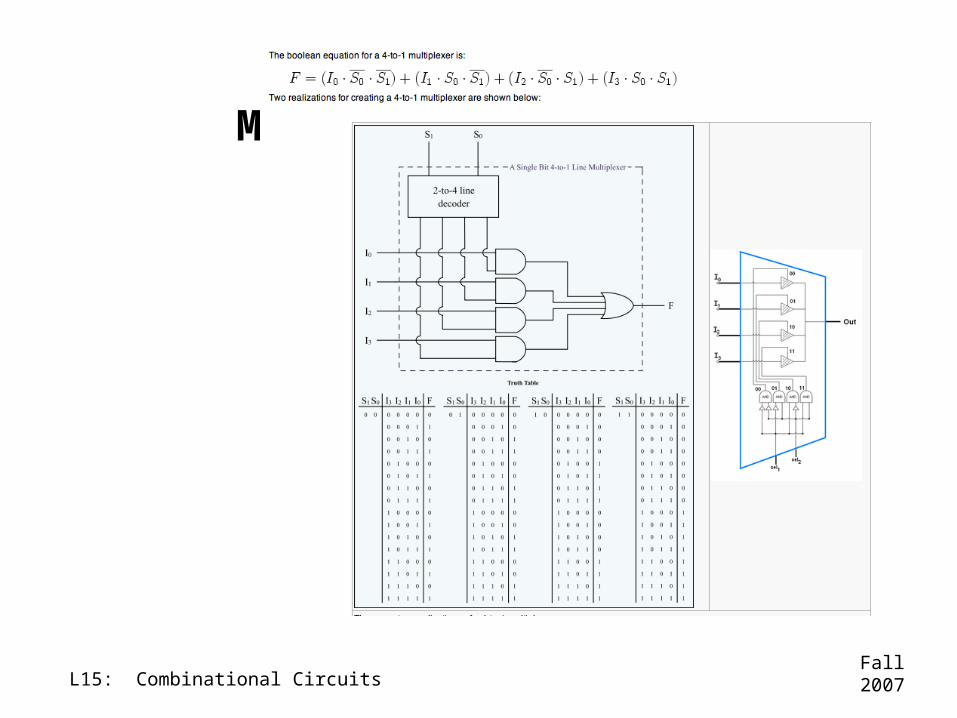
Multiplexers
• Consist of:
–2n data inputs–One output–n control inputs
• Used to control the selection of a single output from n different inputs
• Typical application: parallel to serial converter
D0
D1
D2
D3
A B
Out
4 input multiplexer
Fall 2007L15: Combinational Circuits
Multiplexor Details
Fall 2007L15: Combinational Circuits
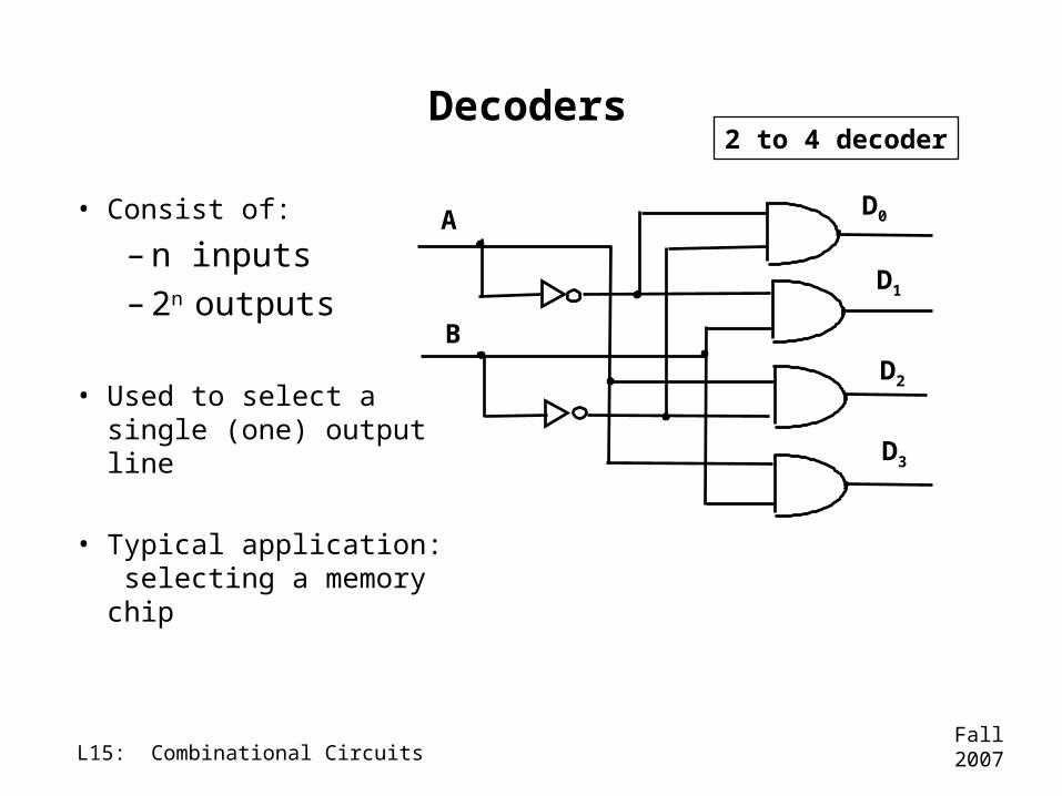
Decoders
• Consist of:
–n inputs–2n outputs
• Used to select a single (one) output line
• Typical application: selecting a memory chip
D0
D1
D2
D3
A
B
2 to 4 decoder
Fall 2007L15: Combinational Circuits
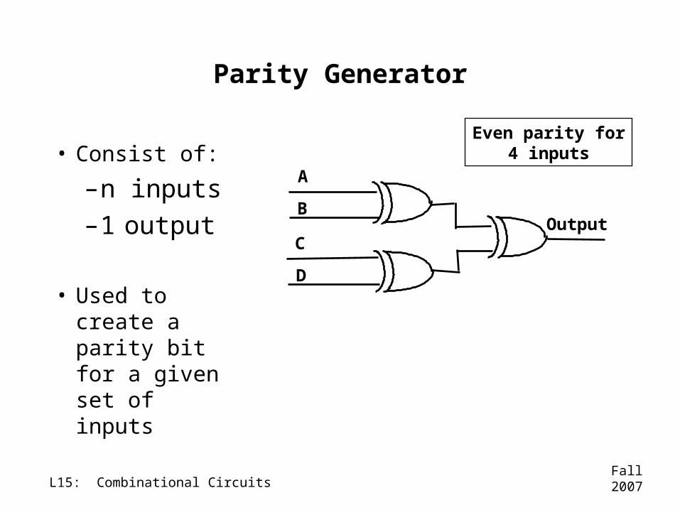
Parity Generator
• Consist of:
–n inputs–1 output
• Used to create a parity bit for a given set of inputs
A
BOutput
C
D
Even parity for4 inputs
Fall 2007L15: Combinational Circuits
Arithmetic Logic Units (ALUs)
• The ALU is the math engine for modern digital computers
Fall 2007L15: Combinational Circuits
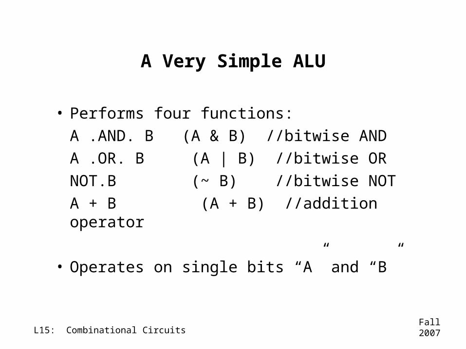
A Very Simple ALU
• Performs four functions:A .AND. B (A & B) //bitwise ANDA .OR. B (A | B) //bitwise ORNOT.B (~ B) //bitwise NOTA + B (A + B) //addition operator
• Operates on single bits “A” and “B”
Fall 2007L15: Combinational Circuits
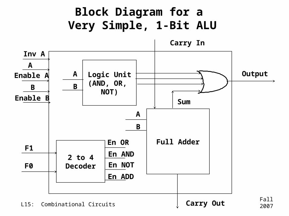
Block Diagram for a Very Simple, 1-Bit ALU
Logic Unit(AND, OR,
NOT)
A
B
Full Adder
2 to 4Decoder
Output
Carry Out
Carry In
Enable A
Enable B
Inv A
F1
F0
Sum
A
B
En OR
En AND
En NOT
En ADD
A
B
Fall 2007L15: Combinational Circuits
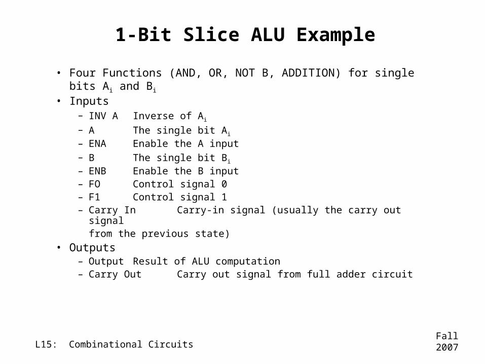
1-Bit Slice ALU Example
• Four Functions (AND, OR, NOT B, ADDITION) for single bits Ai and Bi
• Inputs– INV A Inverse of Ai
– A The single bit Ai
– ENA Enable the A input– B The single bit Bi
– ENB Enable the B input– FO Control signal 0– F1 Control signal 1– Carry In Carry-in signal (usually the carry out signal
from the previous state)• Outputs
– Output Result of ALU computation– Carry Out Carry out signal from full adder circuit
Fall 2007L15: Combinational Circuits
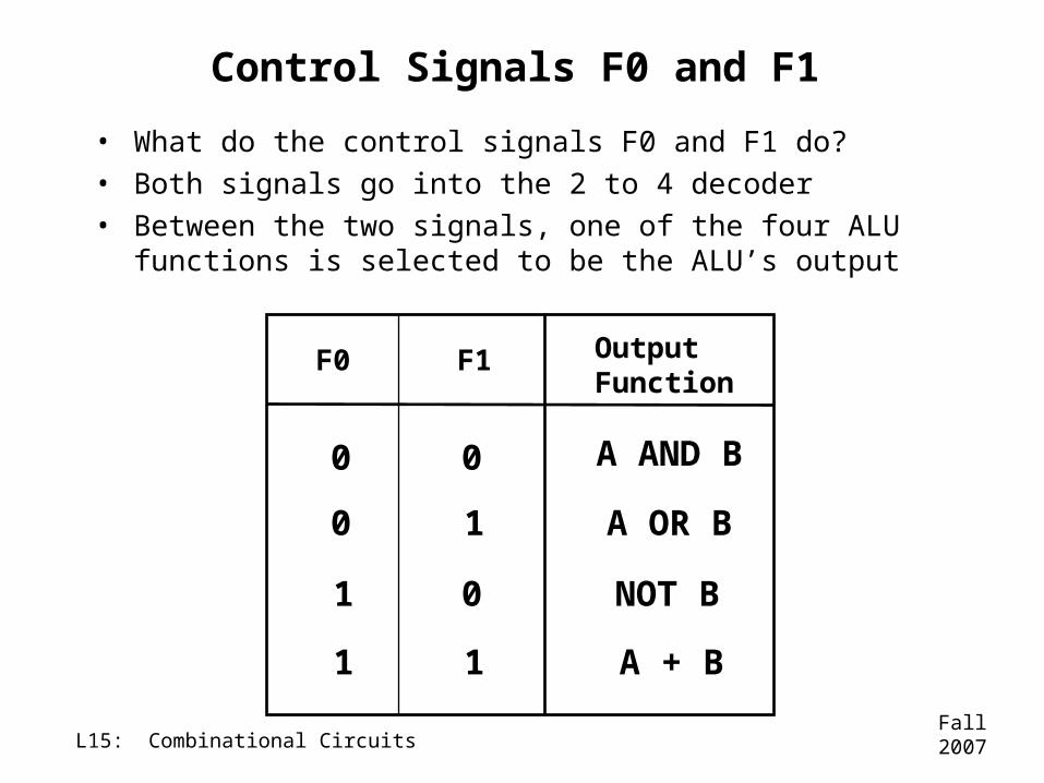
Control Signals F0 and F1
• What do the control signals F0 and F1 do?• Both signals go into the 2 to 4 decoder• Between the two signals, one of the four ALU
functions is selected to be the ALU’s output
F0 OutputFunction
0 A AND B
A + B
1
F1
0
A OR B
NOT B
0
01
1 1
Fall 2007L15: Combinational Circuits
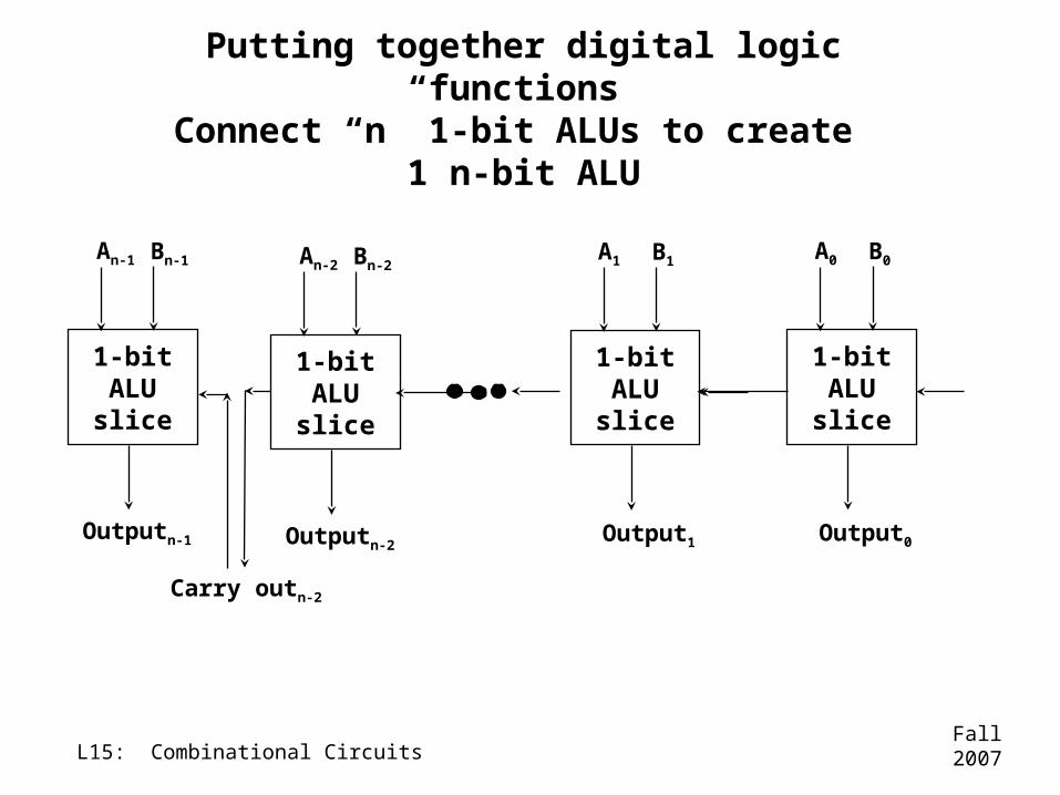
Putting together digital logic functions
Connect “n” 1-bit ALUs to create 1 n-bit ALU
1-bitALUslice
An-1 Bn-1
Outputn-1
1-bitALUslice
A1 B1
Output1
1-bitALUslice
A0 B0
Output0
1-bitALUslice
An-2 Bn-2
Outputn-2
Carry outn-2
Fall 2007L15: Combinational Circuits
More Complex ALUs
• ALUs in modern CPUs can include more functions than the four we just put together
• For example, other functions that might be useful:
–multiply–shift–compare
Fall 2007L15: Combinational Circuits
How would you get the ALU to subtract two integers?
• A – B
• Think about the two’s complement procedure1. NOT B (take the complement of B)2. NOTB + 1 (add one to the result of
step 1)3. (NOTB + 1) + A (add A to the result of step
2)4. Ignore any carry out signals
Fall 2007L15: Combinational Circuits
What additional function would we need to be able to multiply and
divide integers?
• Shifters (left shift and right shift)
• Multiplication and division can be thought of as “shift and add” or “shift and subtract” procedures
We don’t have time to build a multiplier, but this should give you the intuition for how it could be done.
Fall 2007L15: Combinational Circuits
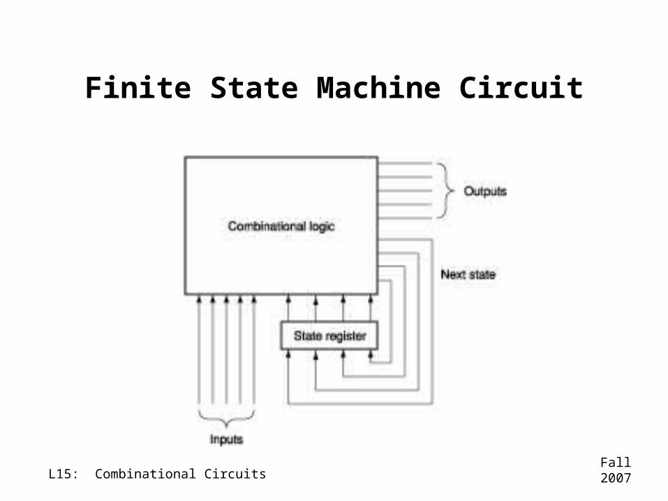
Finite State Machines
A formal model used to design sequential circuits to perform tasks that only require a finite number of distinct states of the
flip flops
Fall 2007L15: Combinational Circuits
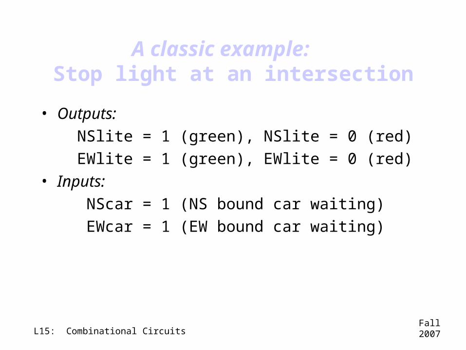
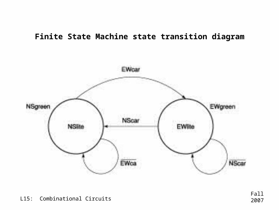
A classic example: Stop light at an intersection
• Outputs: NSlite = 1 (green), NSlite = 0 (red) EWlite = 1 (green), EWlite = 0 (red)• Inputs: NScar = 1 (NS bound car waiting) EWcar = 1 (EW bound car waiting)
Fall 2007L15: Combinational Circuits
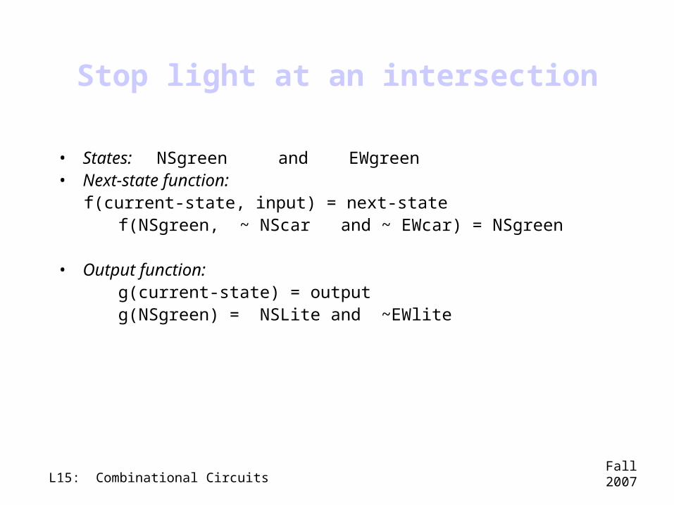
Stop light at an intersection
• States: NSgreen and EWgreen• Next-state function: f(current-state, input) = next-state f(NSgreen, ~ NScar and ~ EWcar) = NSgreen • Output function: g(current-state) = output g(NSgreen) = NSLite and ~EWlite
Fall 2007L15: Combinational Circuits
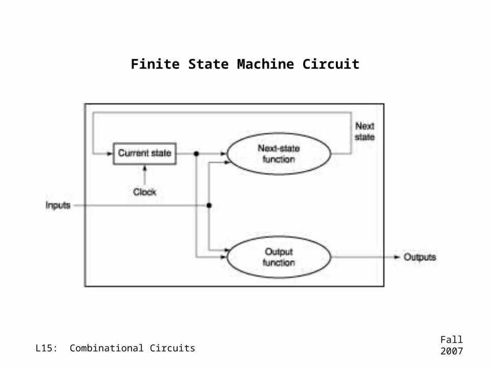
Finite State Machine Circuit
Fall 2007L15: Combinational Circuits
Finite State Machine state transition diagram
Fall 2007L15: Combinational Circuits
Finite State Machine Circuit
Fall 2007L15: Combinational Circuits
Other common finite state machines in the processor
• Counters• Shift registers