Failure Modes, Effects and Diagnostic Analysisus.magnetrol.com/Literature/1/FMEDA E3...
21
The document was prepared using best effort. The authors make no warranty of any kind and shall not be liable in any event for incidental or consequential damages in connection with the application of the document. © All rights reserved. Failure Modes, Effects and Diagnostic Analysis Project: E3 Modulevel Level Displacer Transmitter Company: Magnetrol Downers Grove, IL USA Contract Number: Q08/03-66r1 Report No.: MAG 08/03-66 R001 Version V1, Revision R1, September 22, 2008 John Grebe
Transcript of Failure Modes, Effects and Diagnostic Analysisus.magnetrol.com/Literature/1/FMEDA E3...

The document was prepared using best effort. The authors make no warranty of any kind and shall not be liable in any event for incidental or consequential damages in connection with the application of the document.
© All rights reserved.
Failure Modes, Effects and Diagnostic Analysis
Project:
E3 Modulevel Level Displacer Transmitter
Company: Magnetrol
Downers Grove, IL USA
Contract Number: Q08/03-66r1 Report No.: MAG 08/03-66 R001
Version V1, Revision R1, September 22, 2008 John Grebe

© exida Consulting LLC MAG 08-03-66r1 R001 V0 R1 FMEDA E3 Modulevel.doc John Grebe Page 2 of 21
Management Summary This report summarizes the results of the hardware assessment in the form of a Failure Modes, Effects, and Diagnostic Analysis (FMEDA) of the E3 Modulevel Level Displacer Transmitter. A Failure Modes, Effects, and Diagnostic Analysis is one of the steps to be taken to achieve functional safety certification per IEC 61508 of a device. From the FMEDA, failure rates and Safe Failure Fraction are determined. The FMEDA that is described in this report concerns only the hardware of the E3 Modulevel Level Displacer Transmitter. For full functional safety certification purposes all requirements of IEC 61508 will be considered.
The E3 Modulevel Level Displacer Transmitter is a digital process transmitter. Its current output signal is intended to provide the primary process variable which is the level or interface or density measurement value. The device has internal self diagnostics which upon detection of a failure, sends the analog output to a predefined out of range analog current. The logic solver must be programmed to measure these out of range currents and interpret them as a failure.
The Safety Function of the E3 Modulevel Level Displacer Transmitter shall be to monitor the level or interface of a liquid or its density and transmit a 4-20mA analog signal within the measurement safety accuracy.
Figure 1 E3 Modulevel Level Displacer Transmitter and Displacer
For safety instrumented systems usage it is assumed that the 4 – 20 mA output is used as the safety variable for level or density measurement.
Table 1 gives an overview of the different versions that were considered in the FMEDA of the E3 Modulevel Level Displacer Transmitter.
Table 1 Version Overview

© exida Consulting LLC MAG 08-03-66r1 R001 V0 R1 FMEDA E3 Modulevel.doc John Grebe Page 3 of 21
Integral Mount E3 Modulevel
E3 Modulevel Level Displacer Transmitter with local mounting of the transmitter at the process sensor
Remote Mount E3 Modulevel
E3 Modulevel Level Displacer Transmitter with optional remote mounting of the transmitter
The E3 Modulevel Level Displacer Transmitter is classified as a Type B1 device according to IEC 61508, having a hardware fault tolerance of 0.
The analysis shows that the device has a Safe Failure Fraction between 90% and 99% (assuming that the logic solver is programmed to detect over-scale and under-scale currents) and therefore meets architecture constraints of IEC 61508 for up to SIL 2 as a single device.
The failure rates for the E3 Modulevel Level Displacer Transmitter are listed in Table 2.
Table 2 Failure rates Integral Mount E3 Modulevel Level Displacer Transmitter
Failure Category Failure Rate (FIT) Fail Safe Undetected 21
Fail Dangerous Detected 540
Fail Detected (detected by internal diagnostics) 472
Fail High (detected by logic solver) 25
Fail Low (detected by logic solver) 43
Fail Dangerous Undetected 59
Residual Effect 138
Annunciation Undetected 11
The failure rates for a Remote Mount E3 Modulevel Level Displacer Transmitter are listed in Table 3.
1 Type B device: “Complex” component (using micro controllers or programmable logic); for details see 7.4.3.1.3 of IEC 61508-2.
© exida Consulting LLC MAG 08-03-66r1 R001 V0 R1 FMEDA E3 Modulevel.doc John Grebe Page 4 of 21
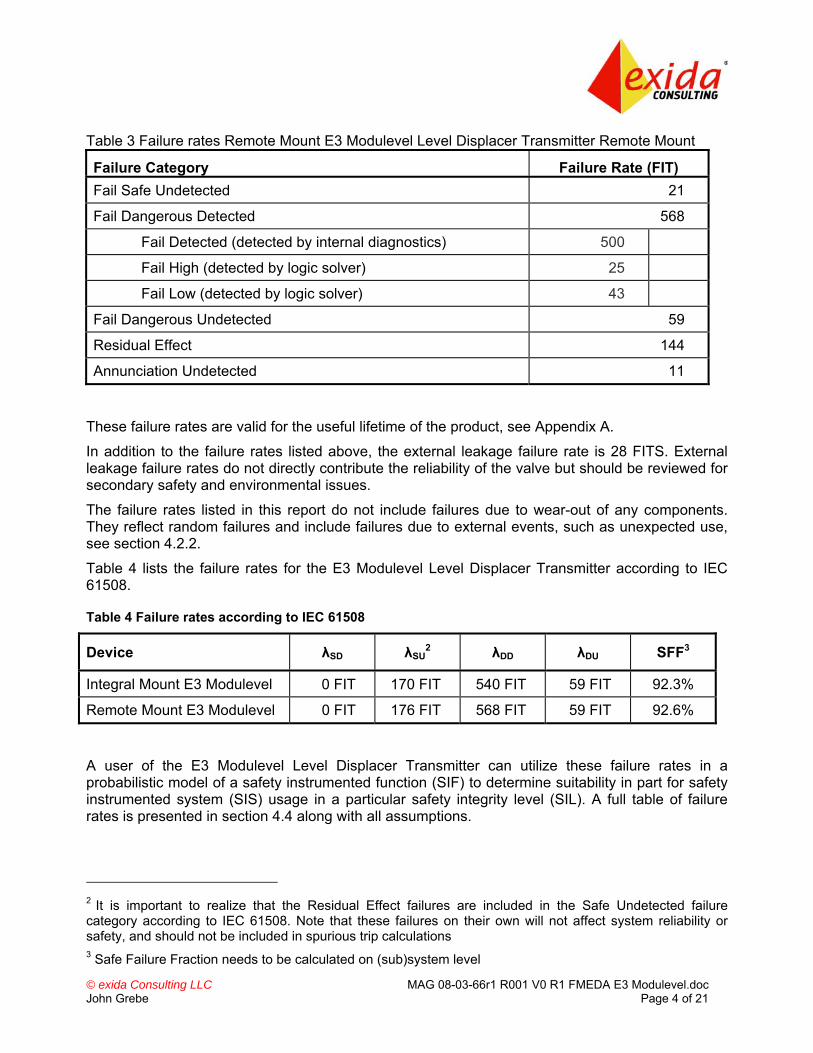
Table 3 Failure rates Remote Mount E3 Modulevel Level Displacer Transmitter Remote Mount
Failure Category Failure Rate (FIT) Fail Safe Undetected 21
Fail Dangerous Detected 568
Fail Detected (detected by internal diagnostics) 500
Fail High (detected by logic solver) 25
Fail Low (detected by logic solver) 43
Fail Dangerous Undetected 59
Residual Effect 144
Annunciation Undetected 11
These failure rates are valid for the useful lifetime of the product, see Appendix A.
In addition to the failure rates listed above, the external leakage failure rate is 28 FITS. External leakage failure rates do not directly contribute the reliability of the valve but should be reviewed for secondary safety and environmental issues.
The failure rates listed in this report do not include failures due to wear-out of any components. They reflect random failures and include failures due to external events, such as unexpected use, see section 4.2.2.
Table 4 lists the failure rates for the E3 Modulevel Level Displacer Transmitter according to IEC 61508.
Table 4 Failure rates according to IEC 61508
Device λSD λSU2 λDD λDU SFF3
Integral Mount E3 Modulevel 0 FIT 170 FIT 540 FIT 59 FIT 92.3%
Remote Mount E3 Modulevel 0 FIT 176 FIT 568 FIT 59 FIT 92.6%
A user of the E3 Modulevel Level Displacer Transmitter can utilize these failure rates in a probabilistic model of a safety instrumented function (SIF) to determine suitability in part for safety instrumented system (SIS) usage in a particular safety integrity level (SIL). A full table of failure rates is presented in section 4.4 along with all assumptions.
2 It is important to realize that the Residual Effect failures are included in the Safe Undetected failure category according to IEC 61508. Note that these failures on their own will not affect system reliability or safety, and should not be included in spurious trip calculations 3 Safe Failure Fraction needs to be calculated on (sub)system level

© exida Consulting LLC MAG 08-03-66r1 R001 V0 R1 FMEDA E3 Modulevel.doc John Grebe Page 5 of 21
Table of Contents Management Summary ....................................................................................................... 2
1 Purpose and Scope...................................................................................................... 6
2 Project Management .................................................................................................... 7 2.1 exida .................................................................................................................................. 7 2.2 Roles of the parties involved.............................................................................................. 7 2.3 Standards and Literature used .......................................................................................... 7 2.4 Reference documents ....................................................................................................... 8
2.4.1 Documentation provided by Magnetrol ...................................................................... 8 2.4.2 Documentation generated by exida .......................................................................... 8
3 Product Description ...................................................................................................... 9
4 Failure Modes, Effects, and Diagnostic Analysis........................................................ 11 4.1 Failure Categories description......................................................................................... 11 4.2 Methodology – FMEDA, Failure Rates ............................................................................ 12
4.2.1 FMEDA .................................................................................................................... 12 4.2.2 Failure Rates ........................................................................................................... 12
4.3 Assumptions .................................................................................................................... 13 4.4 Results............................................................................................................................. 14
5 Using the FMEDA Results.......................................................................................... 16 5.1 PFDAVG Calculation E3 Modulevel Level Displacer Transmitter ...................................... 16
6 Terms and Definitions ................................................................................................ 17
7 Status of the Document.............................................................................................. 18 7.1 Liability............................................................................................................................. 18 7.2 Releases.......................................................................................................................... 18 7.3 Future Enhancements ..................................................................................................... 18 7.4 Release Signatures ......................................................................................................... 19
Appendix A Lifetime of Critical Components................................................................ 20
Appendix B Proof tests to reveal dangerous undetected faults ................................... 21 B.1 Suggested Proof Test...................................................................................................... 21

© exida Consulting LLC MAG 08-03-66r1 R001 V0 R1 FMEDA E3 Modulevel.doc John Grebe Page 6 of 21
1 Purpose and Scope Generally three options exist when doing an assessment of sensors, interfaces and/or final elements.
Option 1: Hardware assessment according to IEC 61508
Option 1 is a hardware assessment by exida according to the relevant functional safety standard(s) like IEC 61508 or EN 954-1. The hardware assessment consists of a FMEDA to determine the fault behavior and the failure rates of the device, which are then used to calculate the Safe Failure Fraction (SFF) and the average Probability of Failure on Demand (PFDAVG). When appropriate, fault injection testing will be used to confirm the effectiveness of any self-diagnostics.
This option provides the safety instrumentation engineer with the required failure data as per IEC 61508 / IEC 61511. This option does not include an assessment of the development process and therefore prior use justification must be done per IEC 61511 to use the product in a safety instrumented function.
Option 2: Hardware assessment with proven-in-use consideration per IEC 61508 / IEC 61511
Option 2 extends Option 1 with an assessment of the proven-in-use documentation of the device including the modification process.
This option for pre-existing programmable electronic devices provides the safety instrumentation engineer with the required failure data as per IEC 61508 / IEC 61511. When combined with plant specific proven-in-use records, it may help with prior-use justification per IEC 61511 for sensors, final elements and other PE field devices.
Option 3: Full assessment according to IEC 61508
Option 3 is a full assessment by exida according to the relevant application standard(s) like IEC 61511 or EN 298 and the necessary functional safety standard(s) like IEC 61508 or EN 954-1. The full assessment extends Option 1 by an assessment of all fault avoidance and fault control measures during hardware and software development.
This option provides the safety instrumentation engineer with the required failure data as per IEC 61508 / IEC 61511 and confidence that sufficient attention has been given to systematic failures during the development process of the device.
This assessment shall be done according to option 1. This document shall describe the results of the hardware assessment in the form of the Failure Modes, Effects and Diagnostic Analysis carried out on the E3 Modulevel Level Displacer Transmitter. From this, failure rates, Safe Failure Fraction (SFF) and example PFDAVG values are calculated.
The information in this report can be used to evaluate whether a sensor subsystem meets the average Probability of Failure on Demand (PFDAVG) requirements and the architectural constraints / minimum hardware fault tolerance requirements per IEC 61508 / IEC 61511.
© exida Consulting LLC MAG 08-03-66r1 R001 V0 R1 FMEDA E3 Modulevel.doc John Grebe Page 7 of 21
2 Project Management
2.1 exida exida is one of the world’s leading knowledge companies specializing in automation system safety and availability with over 300 years of cumulative experience in functional safety. Founded by several of the world’s top reliability and safety experts from assessment organizations and manufacturers, exida is a partnership with offices around the world. exida offers training, coaching, project oriented consulting services, safety lifecycle engineering tools, detailed product assurance and certification analysis and a collection of on-line safety and reliability resources. exida maintains a comprehensive failure rate and failure mode database on process equipment.
2.2 Roles of the parties involved Magnetrol Manufacturer of the E3 Modulevel Level Displacer Transmitter
exida Performed the hardware assessment according to Option 1 (see Section 1)
Magnetrol contracted exida in August 2008 with the hardware assessment of the above-mentioned device.
2.3 Standards and Literature used The services delivered by exida were performed based on the following standards / literature.
[N1] IEC 61508-2: 2000 Functional Safety of Electrical/Electronic/Programmable
Electronic Safety-Related Systems
[N2] Electrical & Mechanical Component Reliability Handbook, 2006
exida L.L.C, Electrical & Mechanical Component Reliability Handbook, 2006, ISBN 0-9727234-2-0
[N3] Safety Equipment Reliability Handbook, 2nd Edition, 2005
exida L.L.C, Safety Equipment Reliability Handbook, Second Edition, 2005, ISBN 0-9727234-1-2
[N4] Goble, W.M. 1998 Control Systems Safety Evaluation and Reliability, ISA, ISBN #1-55617-636-8. Reference on FMEDA methods
[N5] IEC 60654-1:1993-02, second edition
Industrial-process measurement and control equipment – Operating conditions – Part 1: Climatic condition

© exida Consulting LLC MAG 08-03-66r1 R001 V0 R1 FMEDA E3 Modulevel.doc John Grebe Page 8 of 21
2.4 Reference documents
2.4.1 Documentation provided by Magnetrol [D1] 099-6537, Rev A, 5/23/07 MODULEVEL III, Assembly Drawings [D2] Bullentin 48-640 E3,
Modulevel Displacer Level Transmitter, May 2008
E3 Modulevel® Installation and Operating Manual
[D3] 094-1844-A March 26 2008.pdf
Modulevel III Remote PC Board Schematic
[D4] 094-5062-A Jan 09 2008 Hart Wiring PCB.pdf
HART Wiring Board Schematic Drawing
[D5] 094-605-F Feb 18 2008.pdf Enhanced 705 Digital PC Board Schematic [D6] 094-6060-A March 21
2008.pdf Schematic Modulevel III Analog Board
2.4.2 Documentation generated by exida [R1] Magnetrol E3 Level
Transmitter Mechanical 091708.efm
Failure Modes, Effects, and Diagnostic Analysis – E3 Modulevel Level Displacer Transmitter Electronics (Internal Document)
[R2] Magnetrol E3 Level Transmitter Wiring Bd 091709.efm
Failure Modes, Effects, and Diagnostic Analysis – E3 Modulevel Level Displacer Transmitter Mechanical and Summary (Internal Document)
[R3] Magnetrol E3 Level Transmitter Digital Board 091608.efm
Detailed FMEDA for Digital PC Board
[R4] Magnetrol E3 Level Transmitter Analog Board.efm
Detailed FMEDA for Analog PC Board
[R5] Magnetrol E3 Level Transmitter Remote Board.efm
Detailed FMEDA for Remote PC Board
[R6] Modulevel E3 FMEDA Summary 091708.xls
FMEDA Summary for E3 Modulevel
[R7] MAG 08-03-66r1 R001 V0 R1 FMEDA E3 Modulevel.doc, 09/21/2008
FMEDA report, E3 Modulevel Level Displacer Transmitter (this report)

© exida Consulting LLC MAG 08-03-66r1 R001 V0 R1 FMEDA E3 Modulevel.doc John Grebe Page 9 of 21
3 Product Description The E3 Modulevel Level Displacer Transmitter is a 2 wire, loop-powered Level Transmitter with HART Communication that operates according to the fully proven liquid displacement and range spring principles. A change in liquid level varies the net weight of the displacer, increasing or decreasing the load on the range spring by an amount directly proportional to the change in liquid or interface level or density. The movement of a rod attached to the displacer is sensed by a precision LVDT sensor, producing dual analog signals ratio metric proportional to the process variable being monitored in the vessel. These analog signals are converted to a digital signal that is processed by the on-board micro-controller. After processing, the digital result is converted to a 4-20 mA analog output signal.
The E3 Modulevel Level Displacer Transmitter is a digital full featured process transmitter. It is comprised of three main parts, the Transmitter body, LVDT Sensor Assembly, and the Displacer and Range Spring Assembly. Together they can measure the liquid level, the level of the interface between two liquids, or the density of a liquid. Changes in level or specific gravity exert a buoyant force on the displacer which is translated into a precision linear movement of a moveable core for LVDT sensing by the range spring. The position of the core is then sensed by the instruments electronics and then converted to a 4-20mA output signal. The device has internal self diagnostics which upon detection of a failure sends the analog output to an out of range analog current. The logic solver must be programmed to measure these out of range currents and interpret them as a failure.
The E3 Modulevel Level Displacer Transmitter is a digital full featured process transmitter. Its current output signal is intended to provide the primary process variable which is the level or interface or density measurement value. The device has internal self diagnostics which upon detection of a failure, sends the analog output to a predefined out of range analog current. The logic solver must be programmed to measure these out of range currents and interpret them as a failure.
The Safety Function of the E3 Modulevel Level Displacer Transmitter shall be to monitor the level or interface of a liquid or its density and transmit a 4-20mA analog signal within the measurement safety accuracy.
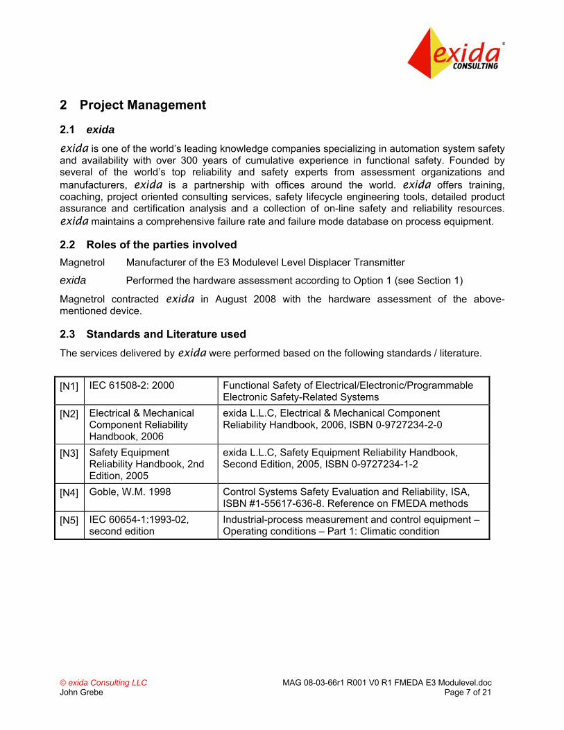
The FMEDA analysis results include the entire transmitter including the electronics and the displacer as shown in Figure 2. The displacer is included but the end user’s tank not part of this evaluation.
© exida Consulting LLC MAG 08-03-66r1 R001 V0 R1 FMEDA E3 Modulevel.doc John Grebe Page 10 of 21
Figure 2 E3 Modulevel Level Displacer Transmitter, Parts included in the FMEDA
Table 5 gives an overview of the different versions that were considered in the FMEDA of the E3 Modulevel Level Displacer Transmitter.
Table 5 Version Overview
Integral Mount E3 Modulevel
E3 Modulevel Level Displacer Transmitter with local mounting of the transmitter at the process sensor
Remote Mount E3 Modulevel
E3 Modulevel Level Displacer Transmitter with optional remote mounting of the transmitter
The E3 Modulevel Level Displacer Transmitter is classified as a Type B6 device according to IEC 61508, having a hardware fault tolerance of 0.
6 Type B device: “Complex” component (using micro controllers or programmable logic); for details see 7.4.3.1.3 of IEC 61508-2.
Transmitter Compartment
Electronic Assemblies
Sensor Signal
Processing A/D
EEPROM
Microprocessor D/A Proportional 4 to 20 mA PV output
Process
FMEDA
LVDT Compartment
Mechanical Assembly
Displacer and Range Spring
LVDT Sensor
Assembly
© exida Consulting LLC MAG 08-03-66r1 R001 V0 R1 FMEDA E3 Modulevel.doc John Grebe Page 11 of 21
4 Failure Modes, Effects, and Diagnostic Analysis The Failure Modes, Effects, and Diagnostic Analysis was performed based on the documentation obtained from Magnetrol and is documented in [D1] to [D6].
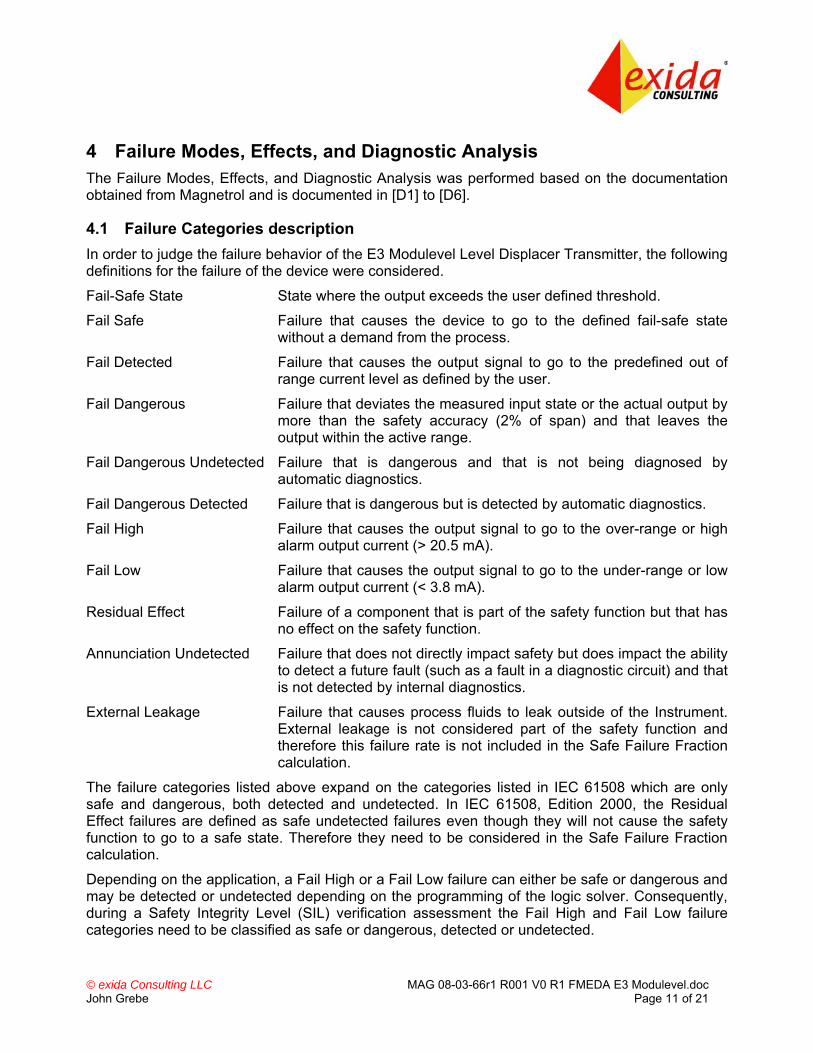
4.1 Failure Categories description In order to judge the failure behavior of the E3 Modulevel Level Displacer Transmitter, the following definitions for the failure of the device were considered.
Fail-Safe State State where the output exceeds the user defined threshold.
Fail Safe Failure that causes the device to go to the defined fail-safe state without a demand from the process.
Fail Detected Failure that causes the output signal to go to the predefined out of range current level as defined by the user.
Fail Dangerous Failure that deviates the measured input state or the actual output by more than the safety accuracy (2% of span) and that leaves the output within the active range.
Fail Dangerous Undetected Failure that is dangerous and that is not being diagnosed by automatic diagnostics.
Fail Dangerous Detected Failure that is dangerous but is detected by automatic diagnostics.
Fail High Failure that causes the output signal to go to the over-range or high alarm output current (> 20.5 mA).
Fail Low Failure that causes the output signal to go to the under-range or low alarm output current (< 3.8 mA).
Residual Effect Failure of a component that is part of the safety function but that has no effect on the safety function.
Annunciation Undetected Failure that does not directly impact safety but does impact the ability to detect a future fault (such as a fault in a diagnostic circuit) and that is not detected by internal diagnostics.
External Leakage Failure that causes process fluids to leak outside of the Instrument. External leakage is not considered part of the safety function and therefore this failure rate is not included in the Safe Failure Fraction calculation.
The failure categories listed above expand on the categories listed in IEC 61508 which are only safe and dangerous, both detected and undetected. In IEC 61508, Edition 2000, the Residual Effect failures are defined as safe undetected failures even though they will not cause the safety function to go to a safe state. Therefore they need to be considered in the Safe Failure Fraction calculation.
Depending on the application, a Fail High or a Fail Low failure can either be safe or dangerous and may be detected or undetected depending on the programming of the logic solver. Consequently, during a Safety Integrity Level (SIL) verification assessment the Fail High and Fail Low failure categories need to be classified as safe or dangerous, detected or undetected.

© exida Consulting LLC MAG 08-03-66r1 R001 V0 R1 FMEDA E3 Modulevel.doc John Grebe Page 12 of 21
The Annunciation failures are provided for those who wish to do reliability modeling more detailed than required by IEC61508. It is assumed that the probability model will correctly account for the Annunciation failures. Otherwise the Annunciation Undetected failures have to be classified as Dangerous Undetected failures according to IEC 61508 (worst-case assumption).
External leakage failure rates do not directly contribute to the reliability of the Transmitter but should be reviewed for secondary safety and environmental issues.
4.2 Methodology – FMEDA, Failure Rates
4.2.1 FMEDA A Failure Modes and Effects Analysis (FMEA) is a systematic way to identify and evaluate the effects of different component failure modes, to determine what could eliminate or reduce the chance of failure, and to document the system in consideration.
A FMEDA (Failure Mode Effect and Diagnostic Analysis) is an FMEA extension. It combines standard FMEA techniques with the extension to identify online diagnostics techniques and the failure modes relevant to safety instrumented system design. It is a technique recommended to generate failure rates for each important category (safe detected, safe undetected, dangerous detected, dangerous undetected, fail high, fail low, etc.) in the safety models. The format for the FMEDA is an extension of the standard FMEA format from MIL STD 1629A, Failure Modes and Effects Analysis.
4.2.2 Failure Rates The failure rate data used by exida in this FMEDA is from the Electrical and Mechanical Component Reliability Handbook which was derived using field failure data from multiple sources and failure data from various databases. The rates were chosen in a way that is appropriate for safety integrity level verification calculations. The rates were chosen to match operating stress conditions typical of an industrial field environment similar to IEC 60654-1, Class D (Outdoor Locations). It is expected that the actual number of field failures due to random events will be less than the number predicted by these failure rates.
For hardware assessment according to IEC 61508 only random equipment failures are of interest. It is assumed that the equipment has been properly selected for the application and is adequately commissioned such that early life failures (infant mortality) may be excluded from the analysis.
Failures caused by external events however should be considered as random failures. Examples of such failures are loss of power, physical abuse, or problems due to intermittent instrument air quality.
The assumption is also made that the equipment is maintained per the requirements of IEC 61508 or IEC 61511 and therefore a preventative maintenance program is in place to replace equipment before the end of its “useful life”. Corrosion, erosion, coil burnout etc. are considered age related (late life) or systematic failures, provided that materials and technologies applied are indeed suitable for the application, in all modes of operation.
The user of these numbers is responsible for determining their applicability to any particular environment. Accurate plant specific data may be used for this purpose. If a user has data collected from a good proof test reporting system that indicates higher failure rates, the higher numbers shall be used. Some industrial plant sites have high levels of stress. Under those conditions the failure rate data is adjusted to a higher value to account for the specific conditions of the plant.
© exida Consulting LLC MAG 08-03-66r1 R001 V0 R1 FMEDA E3 Modulevel.doc John Grebe Page 13 of 21
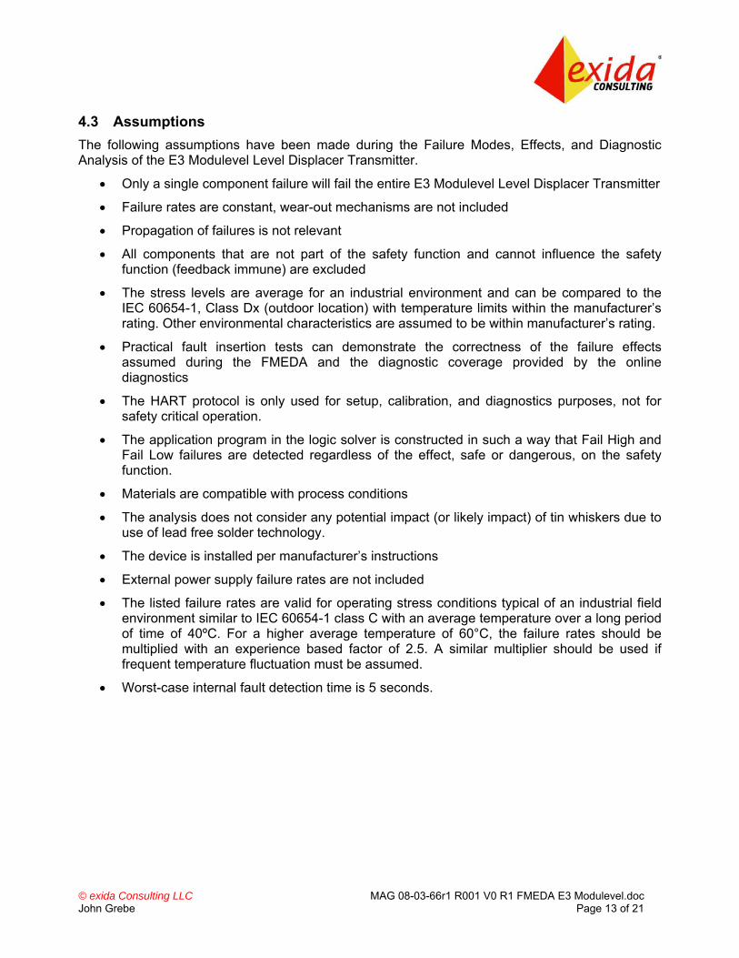
4.3 Assumptions The following assumptions have been made during the Failure Modes, Effects, and Diagnostic Analysis of the E3 Modulevel Level Displacer Transmitter.
• Only a single component failure will fail the entire E3 Modulevel Level Displacer Transmitter
• Failure rates are constant, wear-out mechanisms are not included
• Propagation of failures is not relevant
• All components that are not part of the safety function and cannot influence the safety function (feedback immune) are excluded
• The stress levels are average for an industrial environment and can be compared to the IEC 60654-1, Class Dx (outdoor location) with temperature limits within the manufacturer’s rating. Other environmental characteristics are assumed to be within manufacturer’s rating.
• Practical fault insertion tests can demonstrate the correctness of the failure effects assumed during the FMEDA and the diagnostic coverage provided by the online diagnostics
• The HART protocol is only used for setup, calibration, and diagnostics purposes, not for safety critical operation.
• The application program in the logic solver is constructed in such a way that Fail High and Fail Low failures are detected regardless of the effect, safe or dangerous, on the safety function.
• Materials are compatible with process conditions
• The analysis does not consider any potential impact (or likely impact) of tin whiskers due to use of lead free solder technology.
• The device is installed per manufacturer’s instructions
• External power supply failure rates are not included
• The listed failure rates are valid for operating stress conditions typical of an industrial field environment similar to IEC 60654-1 class C with an average temperature over a long period of time of 40ºC. For a higher average temperature of 60°C, the failure rates should be multiplied with an experience based factor of 2.5. A similar multiplier should be used if frequent temperature fluctuation must be assumed.
• Worst-case internal fault detection time is 5 seconds.
© exida Consulting LLC MAG 08-03-66r1 R001 V0 R1 FMEDA E3 Modulevel.doc John Grebe Page 14 of 21
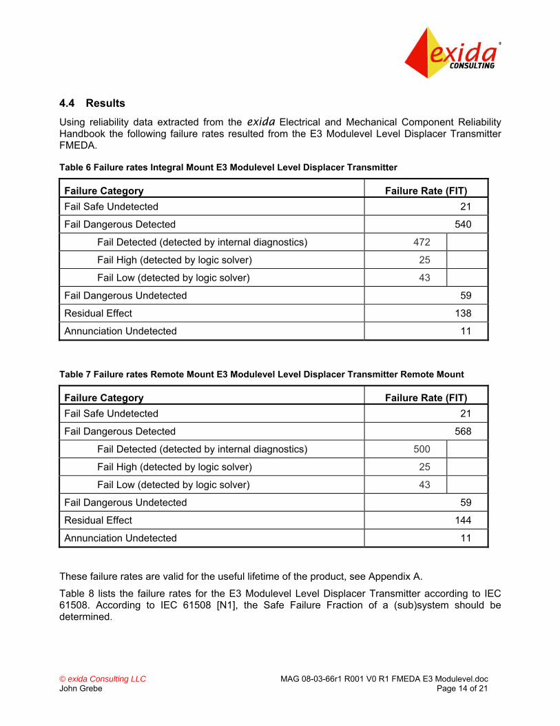
4.4 Results Using reliability data extracted from the exida Electrical and Mechanical Component Reliability Handbook the following failure rates resulted from the E3 Modulevel Level Displacer Transmitter FMEDA.
Table 6 Failure rates Integral Mount E3 Modulevel Level Displacer Transmitter
Failure Category Failure Rate (FIT) Fail Safe Undetected 21
Fail Dangerous Detected 540
Fail Detected (detected by internal diagnostics) 472
Fail High (detected by logic solver) 25
Fail Low (detected by logic solver) 43
Fail Dangerous Undetected 59
Residual Effect 138
Annunciation Undetected 11
Table 7 Failure rates Remote Mount E3 Modulevel Level Displacer Transmitter Remote Mount
Failure Category Failure Rate (FIT) Fail Safe Undetected 21
Fail Dangerous Detected 568
Fail Detected (detected by internal diagnostics) 500
Fail High (detected by logic solver) 25
Fail Low (detected by logic solver) 43
Fail Dangerous Undetected 59
Residual Effect 144
Annunciation Undetected 11
These failure rates are valid for the useful lifetime of the product, see Appendix A.
Table 8 lists the failure rates for the E3 Modulevel Level Displacer Transmitter according to IEC 61508. According to IEC 61508 [N1], the Safe Failure Fraction of a (sub)system should be determined.

© exida Consulting LLC MAG 08-03-66r1 R001 V0 R1 FMEDA E3 Modulevel.doc John Grebe Page 15 of 21
However if the E3 Modulevel Level Displacer Transmitter is only one part of a (sub)system, the SFF should be calculated for the entire sensor combination. The Safe Failure Fraction is the fraction of the overall failure rate of a device that results in either a safe fault or a diagnosed unsafe fault. This is reflected in the following formula for SFF: SFF = 1 - λDU / λTOTAL
Table 8 Failure rates according to IEC 61508
Device λSD λSU7 λDD λDU SFF8
Integral Mount E3 Modulevel 0 FIT 170 FIT 540 FIT 59 FIT 92.3%
Remote Mount E3 Modulevel 0 FIT 176 FIT 568 FIT 59 FIT 92.6% The architectural constraint type for the E3 Modulevel Level Displacer Transmitter is B. The hardware fault tolerance of the device is 0. The SFF and required SIL determine the level of hardware fault tolerance that is required per requirements of IEC 61508 [N1] or IEC 61511. The SIS designer is responsible for meeting other requirements of applicable standards for any given SIL as well.
7 It is important to realize that the Residual Effect failures are included in the Safe Undetected failure category according to IEC 61508. Note that these failures on their own will not affect system reliability or safety, and should not be included in spurious trip calculations 8 Safe Failure Fraction needs to be calculated on (sub)system level
© exida Consulting LLC MAG 08-03-66r1 R001 V0 R1 FMEDA E3 Modulevel.doc John Grebe Page 16 of 21
5 Using the FMEDA Results The following section(s) describe how to apply the results of the FMEDA.
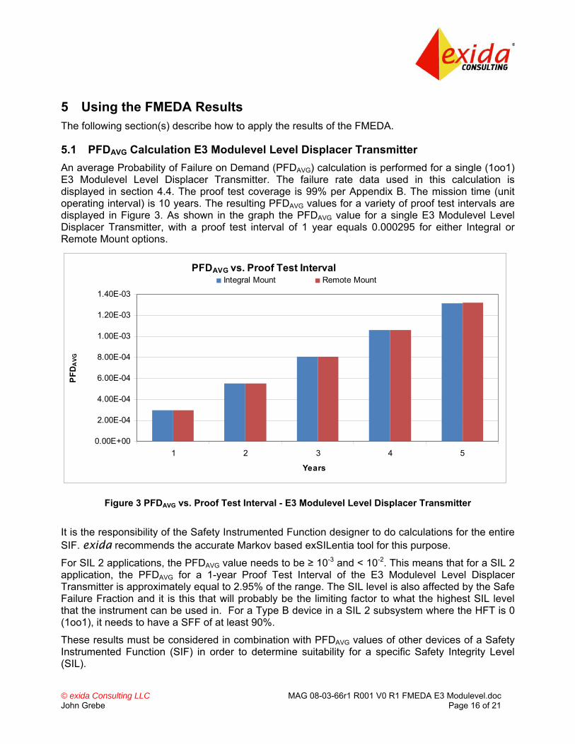
5.1 PFDAVG Calculation E3 Modulevel Level Displacer Transmitter An average Probability of Failure on Demand (PFDAVG) calculation is performed for a single (1oo1) E3 Modulevel Level Displacer Transmitter. The failure rate data used in this calculation is displayed in section 4.4. The proof test coverage is 99% per Appendix B. The mission time (unit operating interval) is 10 years. The resulting PFDAVG values for a variety of proof test intervals are displayed in Figure 3. As shown in the graph the PFDAVG value for a single E3 Modulevel Level Displacer Transmitter, with a proof test interval of 1 year equals 0.000295 for either Integral or Remote Mount options.
PFDAVG vs. Proof Test Interval
0.00E+00
2.00E-04
4.00E-04
6.00E-04
8.00E-04
1.00E-03
1.20E-03
1.40E-03
1 2 3 4 5
Years
PFD
AVG
Integral Mount Remote Mount
Figure 3 PFDAVG vs. Proof Test Interval - E3 Modulevel Level Displacer Transmitter
It is the responsibility of the Safety Instrumented Function designer to do calculations for the entire SIF. exida recommends the accurate Markov based exSILentia tool for this purpose.
For SIL 2 applications, the PFDAVG value needs to be ≥ 10-3 and < 10-2. This means that for a SIL 2 application, the PFDAVG for a 1-year Proof Test Interval of the E3 Modulevel Level Displacer Transmitter is approximately equal to 2.95% of the range. The SIL level is also affected by the Safe Failure Fraction and it is this that will probably be the limiting factor to what the highest SIL level that the instrument can be used in. For a Type B device in a SIL 2 subsystem where the HFT is 0 (1oo1), it needs to have a SFF of at least 90%.
These results must be considered in combination with PFDAVG values of other devices of a Safety Instrumented Function (SIF) in order to determine suitability for a specific Safety Integrity Level (SIL).
© exida Consulting LLC MAG 08-03-66r1 R001 V0 R1 FMEDA E3 Modulevel.doc John Grebe Page 17 of 21
6 Terms and Definitions FIT Failure In Time (1x10⁻⁹ failures per hour)
FMEDA Failure Mode Effect and Diagnostic Analysis
HFT Hardware Fault Tolerance
Low demand mode Mode, where the frequency of demands for operation made on a safety-related system is no greater than twice the proof test frequency.
PFDAVG Average Probability of Failure on Demand
Safety Accuracy The worse case measurement error between the reported value and actual process conditions that is not considered to be dangerous if not detected by self diagnostics.
SFF Safe Failure Fraction, summarizes the fraction of failures, which lead to a safe state and the fraction of failures which will be detected by diagnostic measures and lead to a defined safety action.
SIF Safety Instrumented Function
SIL Safety Integrity Level
SIS Safety Instrumented System – Implementation of one or more Safety Instrumented Functions. A SIS is composed of any combination of sensor(s), logic solver(s), and final element(s).
Type A component “Non-Complex” component (using discrete elements); for details see 7.4.3.1.2 of IEC 61508-2
Type B component “Complex” component (using micro controllers or programmable logic); for details see 7.4.3.1.3 of IEC 61508-2

© exida Consulting LLC MAG 08-03-66r1 R001 V0 R1 FMEDA E3 Modulevel.doc John Grebe Page 18 of 21
7 Status of the Document
7.1 Liability exida prepares FMEDA reports based on methods advocated in International standards. Failure rates are obtained from a collection of industrial databases. exida accepts no liability whatsoever for the use of these numbers or for the correctness of the standards on which the general calculation methods are based.
Due to future potential changes in the standards, best available information and best practices, the current FMEDA results presented in this report may not be fully consistent with results that would be presented for the identical product at some future time. As a leader in the functional safety market place, exida is actively involved in evolving best practices prior to official release of updated standards so that our reports effectively anticipate any known changes. In addition, most changes are anticipated to be incremental in nature and results reported within the previous three year period should be sufficient for current usage without significant question.
Most products also tend to undergo incremental changes over time. If an exida FMEDA has not been updated within the last three years and the exact results are critical to the SIL verification you may wish to contact the product vendor to verify the current validity of the results.
7.2 Releases Version: V1
Revision: R1
Version History: V1, R1: Released; September 22, 2008
V0, R1: Draft; September 17, 2008
Author(s): John Grebe
Review: V0, R1: William Goble
Release Status: Released
7.3 Future Enhancements At request of client.

© exida Consulting LLC MAG 08-03-66r1 R001 V0 R1 FMEDA E3 Modulevel.doc John Grebe Page 19 of 21
7.4 Release Signatures
Dr. William M. Goble, Principal Partner
John C. Grebe Jr., Principal Engineer

© exida Consulting LLC MAG 08-03-66r1 R001 V0 R1 FMEDA E3 Modulevel.doc John Grebe Page 20 of 21
Appendix A Lifetime of Critical Components According to section 7.4.7.4 of IEC 61508-2, a useful lifetime, based on experience, should be assumed.
Although a constant failure rate is assumed by the probabilistic estimation method (see section 4.2.2) this only applies provided that the useful lifetime9 of components is not exceeded. Beyond their useful lifetime the result of the probabilistic calculation method is therefore meaningless, as the probability of failure significantly increases with time. The useful lifetime is highly dependent on the subsystem itself and its operating conditions.
This assumption of a constant failure rate is based on the bathtub curve. Therefore it is obvious that the PFDAVG calculation is only valid for components that have this constant domain and that the validity of the calculation is limited to the useful lifetime of each component.
It is the responsibility of the end user to maintain and operate the E3 Modulevel Level Displacer Transmitter per manufacturer’s instructions. Furthermore regular inspection should show that all components are clean and free from damage.
As there are no aluminum electrolytic or tantalum electrolytic capacitors used, there are no electrical components that limit the useful lifetime of the system.
Based on general field failure data a useful life period of approximately 15 years is expected for the E3 Modulevel Level Displacer Transmitter.
When plant experience indicates a shorter useful lifetime than indicated in this appendix, the number based on plant experience should be used.
9 Useful lifetime is a reliability engineering term that describes the operational time interval where the failure rate of a device is relatively constant. It is not a term which covers product obsolescence, warranty, or other commercial issues.

© exida Consulting LLC MAG 08-03-66r1 R001 V0 R1 FMEDA E3 Modulevel.doc John Grebe Page 21 of 21
Appendix B Proof tests to reveal dangerous undetected faults According to section 7.4.3.2.2 f) of IEC 61508-2 proof tests shall be undertaken to reveal dangerous faults which are undetected by diagnostic tests. This means that it is necessary to specify how dangerous undetected faults which have been noted during the Failure Modes, Effects, and Diagnostic Analysis can be detected during proof testing.
B.1 Suggested Proof Test The suggested proof test is shown in Table 9 and consists of both a full mechanical range excursion and an analog output test. This test will detect approximately 99% of the possible Dangerous Undetected failures in the device.
Table 9 Suggested Proof Test – E3 Modulevel Transmitter and Displacer
Step Action
1. Bypass the safety function and take appropriate action to avoid a false trip
2. Use HART communications to retrieve any diagnostics and take appropriate action.
3. Send a HART command to the transmitter to go to the high alarm current output and verify that the analog current reaches that value10.
4. Send a HART command to the transmitter to go to the low alarm current output and verify that the analog current reaches that value11.
5. Perform a five-point calibration12 check of the displacer and transmitter over the full working range using process fluids.
6. Remove the bypass and otherwise restore normal operation
10 This tests for compliance voltage problems such as a low loop power supply voltage or increased wiring resistance. This also tests for other possible failures. 11 This tests for possible quiescent current related failures. 12 If the calibration check is performed by any means other than fluids acting on the displacer, this proof test will not detect any failures of the displacer.


![Failure Modes, Effects, and Diagnostic Analysis · 5.1 Impulse line clogging ... edition, ISA, ISBN 97B-1-934394-80-9. Reference on FMEDA methods [N6] IEC 60654 -1:1993-02, second](https://static.fdocuments.us/doc/165x107/5ae736d37f8b9a29048e7c74/failure-modes-effects-and-diagnostic-impulse-line-clogging-edition-isa-isbn.jpg)


![Comparing FMEDA Predicted Failure Rates to OREDA …...companies [3, 4].” OREDA has published six editions of its reliability data handbook in 1984, 1992, 1997, 2002, 2009, and 2015.](https://static.fdocuments.us/doc/165x107/60b89026cb663663f265e7b2/comparing-fmeda-predicted-failure-rates-to-oreda-companies-3-4a-oreda.jpg)

![Failure Modes, Effects and Diagnostic Analysis · 2020. 4. 16. · [N13] Using a Failure Modes, Effects and Diagnostic Analysis (FMEDA) to Measure Diagnostic Coverage in Programmable](https://static.fdocuments.us/doc/165x107/60e2651580b5c87529333b66/failure-modes-effects-and-diagnostic-analysis-2020-4-16-n13-using-a-failure.jpg)