
Failure Investigations on Electrical Motors and...
43
© ERA Technology Limited Failure Analysis 1 Failure Investigations on Electrical Motors and Transformers Dr Morris Lockwood – Technical Manager, Power systems, ERA Technology Ltd
Transcript of Failure Investigations on Electrical Motors and...

© ERA Technology Limited Failure Analysis 1
Failure Investigations on Electrical Motors and
Transformers Dr Morris Lockwood – Technical Manager, Power systems, ERA Technology Ltd

© ERA Technology Limited Failure Analysis 2 2
Summary
• Intended audience
• What is a failure and the consequences of failure
• The time element :
• Early life failures
• Mid life failures
• End of life failures
• The evolution of arcing failures
• Investigating failures

© ERA Technology Limited Failure Analysis 3 3
Intended audience
• The talk is aimed at :
• Brokers
• Underwriters
• Claims personnel from Insurers
• I have been told that the audience will be particularly
interested in the Energy sector and offshore equipment
• Most of the examples are land based but similar equipment is
used offshore
• I have assumed that at least some of the audience are not
familiar with the engineering aspects of electrical equipment
• The talk will contain a minimum of technical details.
• I will be happy to expand on any particular points you wish to
raise

© ERA Technology Limited Failure Analysis 4 4
What is a failure and the
consequences of failure
• In the context of this talk a failure is an equipment
malfunction which may give rise to an insurance claim.
• The malfunction might be due to an inherent defect due
to poor materials, design or workmanship, or due to
wear and tear etc
• The consequences of the failure often far outweigh the
value of the failed element.
• The talk will look at electrical failures with an emphasis
on transformers and rotating machinery (motors and
generators)
• An example of chiller motor problem ….

© ERA Technology Limited Failure Analysis 5 5
Chiller motor problem- Part 1
• Case history – multiple “Motor Soft Start” failures.
• Used for starting 415V, 250 kW chiller motors in a prestige building
complex in S.E. London.
• LOTS of failures – about to become a legal dispute.
• Epidemiology indicated a problem with a newly redesigned
electronics board – opto-isolators were failing on over-voltage
indicating voltages in excess of 1 kV

© ERA Technology Limited Failure Analysis 6 6
Chiller motor problem- Part 2
• The chiller motors were refrigerant immersed.
• There had not been any change in design of the motor nor the
refrigerant.
• Build-up of static charge was suspected.
• This was confirmed using a vane type electrostatic voltmeter.
• Detailed examination of the circuit diagrams for the old and new
circuit boards revealed that 3 resistors which gave an earth
reference had been omitted!

© ERA Technology Limited Failure Analysis 7 7
Chiller motor problem- Part 3
• Conclusions
• All first failures should be investigated
• Two similar failures is almost a guarantee of further failures.
• Multiple failures can destroy business confidence.

© ERA Technology Limited Failure Analysis 8 8
The time element
• Early life failures:
• Manufacturing failures – non-EU manufactured
transformers examples.
• Materials defects – East European steel example.
• Design failures – hospital generator example.
• Commissioning failures – Dutch CT example
• System issues – Emirates transformer example
• Mid life failures – fewer but still important :
• Manufacturing failures – Voltage transformer
examples.
• End of life failures:
• Long term degradation – transformer insulation aging
etc.
• Motors and generators – end winding failure due to
multiple starts / load transients

© ERA Technology Limited Failure Analysis 9 9
Early life failure –
transformer example
• Manufacture of transformers relocated to Turkey and other countries
• ABB, Alstom, Siemens have all done this
• The result is a very high rate of failure.

© ERA Technology Limited Failure Analysis 10 10
Mid life failure – 27.5 kV voltage
transformer example
• Manufacturing defect allowed moisture to enter bushing – led to very
explosive failure

© ERA Technology Limited Failure Analysis 11 11
Mid life failure – 27.5 kV voltage
transformer example - continued

© ERA Technology Limited Failure Analysis 12 12
End of life failure –
overheated reactor

© ERA Technology Limited Failure Analysis 13 13
End of life failure –
overheated reactor – site of arcing

© ERA Technology Limited Failure Analysis 14 14
Offshore example –
Angola sunrise FPSO

© ERA Technology Limited Failure Analysis 15 15
Emergency Power
battery room fire
• Large array of NiCad cells.
• Each a metal can in a plastic
pouch.
• One leak detectable and not a
major problem.
• Two leaks creates a short circuit
and fire.
• The monitor alarms were
ignored
• TWICE – two fires!

© ERA Technology Limited Failure Analysis 16 16
Arcing failures
• Most power electrical failures result in arcing
• Arcs are lightweight tubes of incandescent atoms.
• Very high currents can flow.
• Currents produce magnetic fields
• A current in a magnetic filed produces a force
• Arc forces are proportional to the square of current
• Therefore the direction of force is independent from the
polarity of the current flow.
• The forces are always away from the energy source.

© ERA Technology Limited Failure Analysis 17 17
Arcing along switch
panel busbars

© ERA Technology Limited Failure Analysis 18 18
Arcing along switch
panel busbars - continued

© ERA Technology Limited Failure Analysis 19 19
Arcing along switch
panel busbars - continued

© ERA Technology Limited Failure Analysis 20 20
Investigating failures –
preservation of evidence
• Most companies do not have procedures in place to handle failures.
• Critical evidence can be lost.
• Suppliers or manufacturers have a vested interest and should not be
allowed near the failed equipment unaccompanied.

© ERA Technology Limited Failure Analysis 21 21
Investigating failures –
preservation of evidence

© ERA Technology Limited Failure Analysis 22 22
Investigating failures –
preservation of evidence

© ERA Technology Limited Failure Analysis 23 23
Investigating failures –
preservation of evidence
• Witness statements, both written and verbal can be critical.
• Cultural differences can make things difficult in overseas
investigations.
• Loss adjusters should prevent disturbance of the failure site as
much as practical.
• An example :

© ERA Technology Limited Failure Analysis 24 24
Case History – Failed super-grid
transformer

© ERA Technology Limited Failure Analysis 25 25
Case History – Failed super-grid
transformer

© ERA Technology Limited Failure Analysis 26 26
Bailing out !

© ERA Technology Limited Failure Analysis 27 27
Bailing out !

© ERA Technology Limited Failure Analysis 28 28
Bailing out !

© ERA Technology Limited Failure Analysis 29 29
Investigating failures –
The process
• Before looking at any physical evidence get a clear briefing on the
circumstances leading up to the failure.
• In particular, had there been any changes or odd things happening?
• Look for evidence from protective devices in the system.
• Look at the failure without preconceptions.
• Get a feel for the equipment structure and power flows.
• Identify hypothetical failure mechanisms.
• Look for confirmatory evidence.
• REPORTING !

© ERA Technology Limited Failure Analysis 30 30
Partial discharge – tracking trees
and worm holes - Part 1
• Electrical stress in mixed dielectric systems is in the inverse
ratio of the relative permittivities
• The relative permittivity of air is 1
• The relative permittivity of insulation is of the order of 5
• Therefore voids in insulation material concentrate stress
• If the dielectric strength of the void is exceeded, there is a tiny
spark – a “partial discharge”

© ERA Technology Limited Failure Analysis 31 31
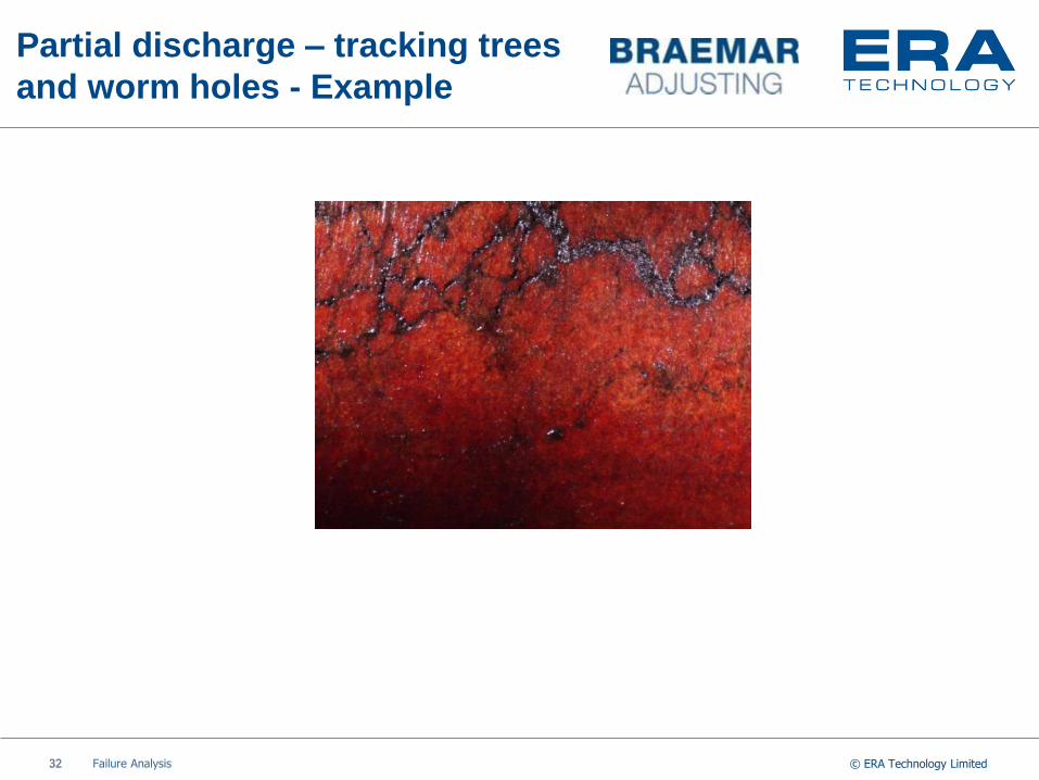
Partial discharge – tracking trees
and worm holes - Part 2
• The partial discharge relieves the excess stress but carbonises
the material near the void.
• This tends to add to the stress concentration and the process
repeats.
• The carbonisation grows in trees and wormholes until a
catastrophic failure occurs.
© ERA Technology Limited Failure Analysis 32 32
Partial discharge – tracking trees
and worm holes - Example

© ERA Technology Limited Failure Analysis 33 33
Contacts – Hot stuff
• Electrical contacts depend on plastic deformation of the contact
materials.
• Actual conduction area is tiny.
• Pressure is required to penetrate the surface contamination –
oxides, sulphates etc.
• Lack of pressure or excessive contamination lead to small area of
contact followed by over-heating, oxidation, relaxation, arcing and
failure. See example .

© ERA Technology Limited Failure Analysis 34 34
Contacts – Example
Hydrogen Sulphide contamination

© ERA Technology Limited Failure Analysis 35 35
Contacts – Example Hydrogen
Sulphide contamination

© ERA Technology Limited Failure Analysis 36 36
Blowing in the wind –
a case of poor house keeping.
• A prestigious bank had dual redundant UPS back-to-back.
• The UPS company were carrying out a routine maintenance check.
• The technician opened the door to one of the two UPS.
• The other UPS suffered a serious arcing failure.
• The two UPS shared a common under-cabinet void.
• Inspection of the void revealed :
• Cleanliness is next to godliness …
© ERA Technology Limited Failure Analysis 37 37
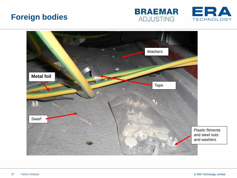
Foreign bodies
Plastic fitments
and steel nuts
and washers
Tape
Washers
Metal foil
Swarf

© ERA Technology Limited Failure Analysis 38 38
The smoking gun

© ERA Technology Limited Failure Analysis 39 39
Blowing in the wind – a case of
poor house keeping - continued.
• Around a quarter of failures in electrical equipment are due to
foreign bodies or other visually obvious causes like water ingress,
chemical contamination, biological contamination.
• Cleanliness is next to
godliness …

© ERA Technology Limited Failure Analysis 40 40
Evolution of a transformer failure –
photograph taken some time after
the explosion (or whoosh)

© ERA Technology Limited Failure Analysis 41 41
Evolution of a
transformer failure
• This was a 140 kVA, 33 kV to 400 V three phase oil-filled
transformer.
• The manufacturers had had a series of failures – mainly associated
with poor quality high voltage windings.
• The fault was so severe the
tank was split along two edge
seams.
• The reaction force of the
expelled oil moved the unit
• about 0.5 metre.

© ERA Technology Limited Failure Analysis 42 42
Evolution of a transformer
failure – Current traces
0
100
200
300
400
500
600
700
800
900
1000
1 1.5 2 2.5 3 3.5 4 4.5 5 5.5 6
IA
IB

© ERA Technology Limited Failure Analysis 43 43
The time element
• Early life failures:
• Manufacturing failures – non-EU manufactured
transformers examples.
• Materials defects – East European steel example.
• Design failures – hospital generator example.
• Commissioning failures – Dutch CT example
• System issues – Emirates transformer example
• Mid life failures – fewer but still important :
• Manufacturing failures – Voltage transformer
examples.
• End of life failures:
• Long term degradation – transformer insulation aging
etc.
• Motors and generators – end winding failure due to
multiple starts / load transients


![Investigations on Transient Behavior of an Energy ... · publications analyzing different kind of speed control techniques for various applications of DC Series motors [37, 39, 41].](https://static.fdocuments.us/doc/165x107/5e69a6e5b6b4f7034015a3e2/investigations-on-transient-behavior-of-an-energy-publications-analyzing-different.jpg)


