17221545 Farhan Ali Internship Report NBP Repaired) Repaired)
Upload
naderbahramiCategory
view
233download
0
7/24/2019 Failure Analysis of Weld-repaired B-1900 Turbine Blade Shrouds
http://slidepdf.com/reader/full/failure-analysis-of-weld-repaired-b-1900-turbine-blade-shrouds 1/9
FAILURE ANALYSIS OF WELD-REPAIRED B-1900 TURBINE BLADE SHROUDS
Erik M. Mueller 1, Luis Carney1, Sun Tai Ngin1, John L Yadon1 1 NAVAIR, ISSC Code 4341, Building 793, NAS JAX, Jacksonville, FL 32212-0016
Keywords: Failure analysis, Welding, Hardface, Turbine blade
Abstract
Four turbine blades having a nominal B-1900 composition weresubmitted for failure analysis after cracks were detected or Z-notch failure had occurred at the shroud. The blades were weldrepaired at the shroud edges and returned to service, only to fail
after several hours. The blade repairs involved machining awaythe original material, and then inert gas tungsten arc weldrepairing with a Co-base hardface and B-1900 filler alloy.Analysis of the broken blades found that they had failed from
fatigue. This fatigue was the result of cracks in the heat-affectedzones of the blades created from liquation at the grain boundariesand residual stresses that could not be relieved through the low-ductility weldments. Cracks also developed from precipitation of
brittle secondary phases at the coating-weldment interdiffusion
zone.
Introduction
Nickel-base superalloys are used throughout the aerospaceindustry because they meet the high-temperature mechanical
requirements of the turbine section of modern aircraft engines. Inorder to maximize performance, the blades and vanes used in theturbine section have complex geometrical designs and casting
procedures—precipitation-hardened nickel superalloy components
cannot be forged. The rising costs of new turbine components dueto processing and raw material expenses have created a desire torepair turbine blades and vanes already in service.
Wear and abrasion stemming from vibrations and high-temperature loads are experienced by the blades in the turbinesection during operation. Of their many designed properties, hightemperature wear resistance of Ni superalloys is usually
overlooked. Hardfacing of the blade sections experiencing themost wear has been employed to prolong service life or repairdamaged blades [1]. A hardface is commonly applied by inert gaswelding the coating to the superalloy substrate or a plasma
transferred arc overlay process [1-3]. Cobalt alloys, such asStellite 694, are commonly used to impart wear resistance to the
applied blade surfaces and can be hardened through solid-solutionstrengthening and carbide formation [1, 3-4].
Previous studies have documented the difficulty in welding
precipitation-hardened Ni-based superalloys [5-7]. The
weldability has been directly correlated to the Ti and Alconcentrations [5] as well as the amount of boron, zirconium, andcarbon present [7-8]. A Ti composition above 6 wt% and/or and
Al composition above 3 wt% will make the alloy susceptible tointergranular cracking in the heat-affected zone (HAZ). Themajor cause of cracking is from constitutional liquation at thegrain boundaries [9]. Liquation occurs when elements comprising
second phases go into solution with the γ-Ni phase, forming lower
melting eutectics at the grain boundaries. This most readily
occurs when large amounts of γ’, carbides, and/or borides are present at the grain boundaries [10-11]. In addition, excess
precipitation of these secondary phases following weld repair canreduce the solid solution strength near the grain boundaries [12]
and can create large shrinkage stresses during cooling [13],making them more susceptible to cracking. Other causes, such ashigh lattice mismatch between precipitate and matrix, and lowductility of the filler metal (in this study the hardface and filler),
have been found to contribute to intergranular cracking [14].
Studies have been performed using stress-distribution models andX-ray diffraction [15] or neutron diffraction [16] that determined
the maximum magnitude of residual stress is located in the heat-affected zone less than 5 mm from the weld line. Post-weld heattreatments (PWHT) are often performed in order to relieve thesestresses. However, these heat-treatments often initiate grain
boundary microcracking due to the excess precipitation and
liquation [8-11, 17]. This has also been linked to low ductilityweld fillers that cannot yield to relieve residual stresses in the
substrate HAZ [14, 18]. Careful control of the weld power andspeed can reduce susceptibility to liquation, microporosity, andsolidification cracking [19]. Careful control of grain orientationand grain geometry can also reduce crack propagation [20].
Overaging pre-weld heat treatments have also been found to beeffective in reducing microcrack susceptibility in the HAZ [21].
In this study, turbine blades that had failed were repaired using a
Stellite 694 hardface gas-tungsten arc weld (GTAW) repair.Some of the repaired blades had fractured after only a short timein service. The purpose of this study was to examine the repairedturbine blades to determine the root cause of failure of crack
indications at the weld.
Methods and Materials
Materials Received
Four J52 1st stage turbine blades were submitted for inspection inthis study. Three blades from one engine (labeled A, B, and C)
while the fourth blade from another engine was labeled M720 (seeFigures 1 and 2). Blades C and M720 had failed in service from a
through crack on the convex side of the blade shroud near the Z-notch. The locations of the crack indications found as describedlater are identified in Figures 1 and 2.
The base material for the blades is nominal B-1900 whose
composition is Ni-8Cr-10Co-6Mo-6Al-4.3Ta-1.0Ti-0.015B-0.08Zr (weight %). The blades were cast from a vacuum-induction melted (VIM) master heat, which was vacuum-arc
remelted (VAR) before conventional casting. The castings werethen heat-treated at 1080°C (1975°F) for 4 hr in an inertatmosphere and then cooled.
Before the final heat treatment, the Z-notch tips were hardfaced
by GTAW with Stellite 694 (Co-28Cr-5Ni-19.5W-1V) in thelocations illustrated in Figure 3. After machining, the entire bladewas then coated with a Cr-based vapor deposition to a minimum
469
Superalloys 2008 Roger C. Reed, Kenneth A. Green, Pierre Caron, Timothy P. Gabb, Michael G. Fahrmann, Eric S. Huron and Shiela A. Woodard
TMS (The Minerals, Metals & Materials Society), 2008

7/24/2019 Failure Analysis of Weld-repaired B-1900 Turbine Blade Shrouds
http://slidepdf.com/reader/full/failure-analysis-of-weld-repaired-b-1900-turbine-blade-shrouds 2/9
20 wt% Cr in the coated area, between 0.015 mm and 0.033 mmthick. Excluding the hardface, the rest of the shroud and part ofthe blade were coated with a pack-aluminization diffusioncoating. Lastly, the casting undergoes the final heat treatment at
898°C (1650°F) for 10 hr in an inert atmosphere, and is then aircooled.
In servicing the worn turbine parts, the blades were repaired by a
welding new shroud tips and notches if cracks were detected between 0.5 and 0.9 mm. This repair involved first machiningaway the coated areas and the cracked regions of the shroud
edges. The tip adjacent to the Z-notch was then hardfaced with aStellite 694 using manual shielded argon gas tungsten-arcwelding. The conditions specified include preheating the blade to
“the melting point of base metal,” welding with a 15 to 28 Acurrent, and a 1.25 mm gap between the surface and electrode tip.After, the remaining shroud area was to be built up with B-1900filler using GTAW. The excess material was electrochemically
ground to the dimensions required for the part. Finally, thematerial was recoated as described above before PWHT (898°Cfor 10 hr in inert atmosphere).
Experimental Procedure
The blades submitted were first non-destructively inspected forcracks using fluorescent penetrant inspection (FPI) and
radiography. The FPI was performed using IAW Type 1, MethodD, Level 4 penetrant as detailed in ASTM E1417. Theradiography was performed using a Tronics Pantak ConventionalX-Ray Unit. The radiographs were obtained digitally using a 120
kV, 4 mA, 1 min exposure.
After non-destructive inspection, the blades were sectioned and
analyzed. Several sections were mounted and polished to 0.3 μm
using a Struers Tegraforce-5 autopolisher. Mounted andunmounted specimens were analyzed using a variety of opticalcameras, as well as a Zeiss Axiovert 200 MAT for opticalmetallography. Specimens were examined at higher
magnification using a Camscan Maxim 2040 SL LaB6 SEM at 20kV. The SEM was equipped with an Oxford Link Pentafet
energy-dispersive X-Ray spectrometer (EDS) and an OxfordMicrospec WDX 600 wavelength-dispersive X-Ray spectrometer(WDS).
Non-Destructive Inspection
Non-destructive inspection using FPI revealed the followinglinear crack indications:
• Blade A: Underneath shroud at concave side
• Blade B: At center of Z-notch on both the convex andconcave sides
• Blade C: Above the far right corner on the convex side
•
Blade M720: On top of the shroud at weld joint near thefractured Z-notch (see Figure 3)
There was concern that sub-surface cracks could also be present.The blades were inspected using radiography. The radiographs(see Figure 4) revealed no cracks other than those previouslydetermined by FPI. Due to the small size and complex geometry
of the blade shrouds, other non-destructive techniques such asultrasound and eddy-current were not successful.
Figure 1. Image of the convex side of the turbine blades withshowing the cracks observed through FPI.
Figure 2. Image of the concave side of the turbine blades with
showing the cracks observed through FPI.
Figure 3. Illustration of the hardface locations of the turbine blade
shrouds (dark grey). Other dimensional definitions are alsoidentified for checking compliance with geometrical
specifications.
470

7/24/2019 Failure Analysis of Weld-repaired B-1900 Turbine Blade Shrouds
http://slidepdf.com/reader/full/failure-analysis-of-weld-repaired-b-1900-turbine-blade-shrouds 3/9
Figure 4. Photograph of the Z-Notch cracks on Blade B on theconvex side. The crack was later found to have penetrated into
the weld material.
Figure 5. Photograph of the Z-notch fracture surface of the M720 blade. The origin is shown on the lower right corner (solid
arrow), and propagates radially (dashed arrows).
Failure Analysis Results
Visual Inspection
Figure 5 illustrates the fracture surface of blade M720 that had
failed near the Z-notch. This surface, and the one from blade C(not pictured), ran parallel to the Z-notch tip tangent. The M720fracture surface exhibited beach marks and fracture lines that ran
back to the lower right corner of Figure 5. The fracture surface of
the C blade was too damaged to make any conclusive
observations at this level.
Metallographic Inspection
Metallographic inspection of the blades revealed cracks thatappeared to emanate on the surface and interior of the blade
perpendicular to the top shroud surface. These flaws were foundin the weld material as well as the substrate. Figure 6 shows an
example one of the cracks identified from FPI. These surface
1 mm
1 mm
Figure 6. Image of Z-notch surface crack in Blade B (25X).
(a)2 mm
20 mμ
(b)
20 μm
Figure 7. Images of cracks in blade B (a) along the interdendritic
regions of the hardface and (b) along the grain boundaries in thefiller material (1000X).
cracks were found to penetrate through the filler material as wellas into the casting substrate. The cracks appeared to preferentially
propagate along the grain boundaries in the base alloy, and alongthe interdendritic regions in the hardface welds (see Figure 7).
471
7/24/2019 Failure Analysis of Weld-repaired B-1900 Turbine Blade Shrouds
http://slidepdf.com/reader/full/failure-analysis-of-weld-repaired-b-1900-turbine-blade-shrouds 4/9
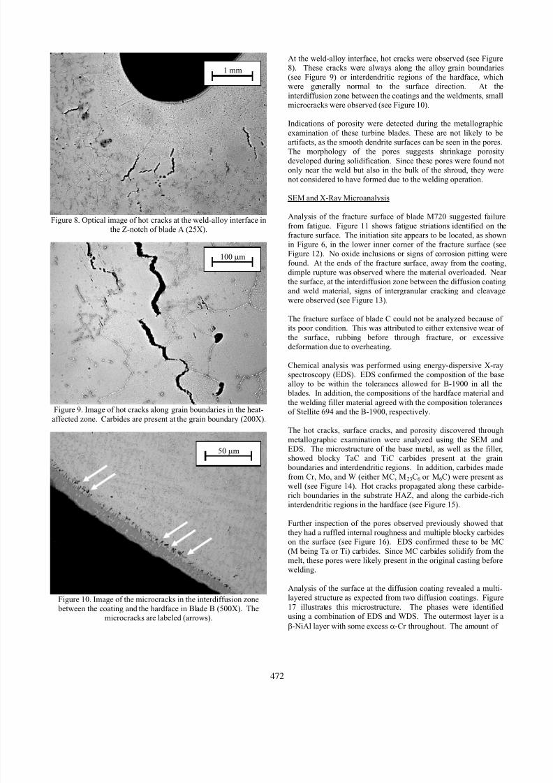
Figure 8. Optical image of hot cracks at the weld-alloy interface in
the Z-notch of blade A (25X).
Figure 9. Image of hot cracks along grain boundaries in the heat-affected zone. Carbides are present at the grain boundary (200X).
Figure 10. Image of the microcracks in the interdiffusion zone between the coating and the hardface in Blade B (500X). The
microcracks are labeled (arrows).
At the weld-alloy interface, hot cracks were observed (see Figure8). These cracks were always along the alloy grain boundaries(see Figure 9) or interdendritic regions of the hardface, whichwere generally normal to the surface direction. At the
interdiffusion zone between the coatings and the weldments, smallmicrocracks were observed (see Figure 10).
1 mm
Indications of porosity were detected during the metallographic
examination of these turbine blades. These are not likely to beartifacts, as the smooth dendrite surfaces can be seen in the pores.The morphology of the pores suggests shrinkage porosity
developed during solidification. Since these pores were found notonly near the weld but also in the bulk of the shroud, they werenot considered to have formed due to the welding operation.
SEM and X-Ray Microanalysis
Analysis of the fracture surface of blade M720 suggested failure
from fatigue. Figure 11 shows fatigue striations identified on thefracture surface. The initiation site appears to be located, as shownin Figure 6, in the lower inner corner of the fracture surface (seeFigure 12). No oxide inclusions or signs of corrosion pitting were
found. At the ends of the fracture surface, away from the coating,
dimple rupture was observed where the material overloaded. Nearthe surface, at the interdiffusion zone between the diffusion coatingand weld material, signs of intergranular cracking and cleavage
were observed (see Figure 13).
100 μm
The fracture surface of blade C could not be analyzed because ofits poor condition. This was attributed to either extensive wear of
the surface, rubbing before through fracture, or excessivedeformation due to overheating.
Chemical analysis was performed using energy-dispersive X-rayspectroscopy (EDS). EDS confirmed the composition of the basealloy to be within the tolerances allowed for B-1900 in all the
blades. In addition, the compositions of the hardface material and
the welding filler material agreed with the composition tolerances
of Stellite 694 and the B-1900, respectively.
The hot cracks, surface cracks, and porosity discovered through
metallographic examination were analyzed using the SEM andEDS. The microstructure of the base metal, as well as the filler,showed blocky TaC and TiC carbides present at the grain
boundaries and interdendritic regions. In addition, carbides made
from Cr, Mo, and W (either MC, M23C6 or M6C) were present aswell (see Figure 14). Hot cracks propagated along these carbide-rich boundaries in the substrate HAZ, and along the carbide-richinterdendritic regions in the hardface (see Figure 15).
50 μm
Further inspection of the pores observed previously showed thatthey had a ruffled internal roughness and multiple blocky carbideson the surface (see Figure 16). EDS confirmed these to be MC
(M being Ta or Ti) carbides. Since MC carbides solidify from themelt, these pores were likely present in the original casting beforewelding.
Analysis of the surface at the diffusion coating revealed a multi-layered structure as expected from two diffusion coatings. Figure
17 illustrates this microstructure. The phases were identifiedusing a combination of EDS and WDS. The outermost layer is a
β-NiAl layer with some excess α-Cr throughout. The amount of
472

7/24/2019 Failure Analysis of Weld-repaired B-1900 Turbine Blade Shrouds
http://slidepdf.com/reader/full/failure-analysis-of-weld-repaired-b-1900-turbine-blade-shrouds 5/9
Figure 11. Secondary electron (SE) micrograph of the fracture
surface of blade M720. The surface shows fatigue striations that propagate from lower right to upper left (arrow).
Figure 12. Backscattered electron (BE) micrograph of the fatiguecrack initiation site on blade M720 (see arrow).
Figure 13. SE micrograph of the fracture surface of blade M720 atthe interdiffusion zone between the weldment and coating.
Figure 14. BE micrograph of a blade A hot crack in the HAZ
below the weld-alloy interface (upper right). The hot crack proceeds along a grain boundary containing a blocky MC carbide
(light phase) and other carbides.
Figure 15. BE micrograph of a blade B surface crack that
propagated into the hardface along the carbide-rich boundaries.
Figure 16. BE micrograph of a pore in blade A.Light phases are carbides present inside the pore.
473

7/24/2019 Failure Analysis of Weld-repaired B-1900 Turbine Blade Shrouds
http://slidepdf.com/reader/full/failure-analysis-of-weld-repaired-b-1900-turbine-blade-shrouds 6/9
α-Cr decreases with increasing distance from the surface. Themiddle layer is an interdiffusion zone between the Cr and Al
diffusion coatings with a variety of phases, including γ’ (Ni3Al) as
well as a large percentage of Cr and Cr-Mo-Nb phases. These phases may or may not be carbides. The compositions suggestthat some chromium carbides, either Cr 23C6 or Cr 6C, are present(with other metals substituting for Cr in varying amounts).
Additionally, a topologically-close packed (TCP) σ phase, with an(Ni,Mo),Cr composition, was detected. No carbon or aluminumwas detected in this phase. Multiple pores and cracks were found
in this middle layer as well (Figure 18). The innermost layer is a
Cr-rich area of the γ-Ni matrix. The Cr content decreases awayfrom the interdiffusion zone until it is the same as the base alloy.
Wavelength-dispersive X-ray spectroscopy (WDS) showed nosigns of S, P, or other impurities commonly associated with hotcracking [7-8]. This includes scans of the diffusion coating, weld-
alloy interface, crack tips, and grain boundaries. Figure 17. BE micrograph of the interdiffusion zone layers between the diffusion coatings and the hardface in blade A.
Blade Geometry and Material Properties Verification
The dimensions of the shroud were compared against the drawing
design specifications. The results are listed in Table I and refer tothe dimensions shown in Figure 3. While generally conforming tospecification, the cross notch is larger than called for, while the
step dimension is less. The M720 blade appeared to deviatefurthest from specification.
Microhardness tests were performed on the hardface weld area
according to ASTM E384. The specimen hardface revealed anaverage hardness of 48 HRC (510 HK 500g). This meets theminimum required hardness of 48 HRC.
Microhardness tests determined that the shroud material in theHAZ was softer than the remainder of the shroud. The hardnessof the shroud adjacent to the weld filler was 30 HRC (310 HK 500g)
whereas the shroud hardness away from the weld, as well as the
blade roots, was 35 HRC (349 HK 500g). The B-1900 fillerexhibited a hardness of 29 HRC (304 HK 500g). There were no
stated mechanical property requirements for these materials or blade areas.
Figure 18. BE micrograph one of the interdiffusion zone cracks
(arrow) is found in the σ phase (light grey phase near arrow).
Analysis and Discussion
Figure 19. Weldability assessment diagram for various nickel- based superalloys [5, 22].
The turbine blades shrouds that failed did so through fatigue propagation of cracks that initiated at or close to the surface insidethe Z-notch. The physically intact, but cracked, blades exhibitedlinear defects on the surface inside the shroud Z-notch, as well as
on the surface near the welds. Internal cracks were also observedoften as hot cracks adjacent to the weld-alloy interface.
A number of issues led to the fatigue failure. It was difficult to
determine which specific causes initiated crack formation, ormerely aided propagation. The primary problem, as has beenreported, appeared to be the low weldability of the B-1900 castingalloy. As shown in Figure 19, the Ti and Al content of the B-1900
compositions places it in the “difficult to weld” region [5, 22].
The low weldability of the substrate alloy is what led to the
formation of hot cracks in the heat-affected zone. Cracks in theHAZ were primarily observed at the grain boundaries. Grain
boundary cracking in Ni-base superalloys has been most
474

7/24/2019 Failure Analysis of Weld-repaired B-1900 Turbine Blade Shrouds
http://slidepdf.com/reader/full/failure-analysis-of-weld-repaired-b-1900-turbine-blade-shrouds 7/9
Table I. Critical dimensions measured on the turbine blade shrouds.
Drawing Requirements Blade A Blade B Blade C Blade M720
Cross Shroud (mm) 26.90 ± 0.05 26.77 26.84 26.88 27.85
Cross Notch (mm) 6.57 ± 0.04 6.985 7.018 6.820 5.883*
Step Dimension (mm) 7.42 ± 0.05” 6.678 6.985 6.683 6.668
Notch Pitch Angle 30° ± 1° 28° 30° 30° 36°
*Measurement of this notch is approximate due to most of the material missing from shroud.
commonly attributed to constitutional liquation [9-11]. The EDSsystem used in this study was unable to detect if there was an
appreciable difference in B or Zr content near and away from thegrain boundaries. However, the grain boundaries did contain alarge amount of MC carbides, which can cause liquation [10-11].
Uncontrolled contraction during cooling of the weldment alloyswas another major source of HAZ cracking. The filler alloy hadthe same composition as the of the cast shroud. Microhardnesstests revealed that the weld filler and adjacent HAZ had similar
hardness. The HAZ was softer than the rest of the casting, likelyfrom improper PWHT and precipitation strengthening.Additionally, the hardface, which was designed to resistdeformation, had a higher hardness than the HAZ or ‘virgin’
material. Welding precipitation-hardened Ni alloys that havelower ductility than the substrate are likely to crack [14, 18]. Inthis case, cracking occurred at the weakest parts of the material:
grain boundaries in the substrate HAZ and filler, andinterdendritic regions in the hardface. These areas were repletewith carbides that, while hard, are also brittle.
According to the drawing supplied, the hardface material was to be applied at the notch tip to impart increased wear resistance.However, the Co-based hardface was also observed inside the Z-notch itself, and the hardface material may lack the toughness to
protect against fatigue crack formation and propagation. Themicrostructure and composition of the hardface matched thatexpected from the design requirements and a previous study.There appeared to be little mixing of the hardface and substrate at
the weld interface. This has been known to lead to TCP formationand cracking [3].
Of particular note is the impact the diffusion coatings had on
crack initiation. SEM analysis revealed microscopic cracks,called leaders, at both the surface and the interdiffusion zone.Leaders are columnar voids between coating grains [23]. Theoutermost layer, as created from the pack aluminization, is mainly
NiAl. While this intermetallic has excellent oxidation resistance,it cannot plastically deform under an applied stress and willfracture [24]. At the Z-notch where the highest stress
concentration is located, NiAl would be unable to relieve stressesin the HAZ or weldment.
In addition, TCP phase (in this case, σ) was detected at theinterdiffusion zone between the coatings and substrate. Often
present in stainless steels and superalloys, σ usually forms inservice from M23C6 carbides in alloys high in Cr, Ta, Nb, W, andMo. The base alloy, filler weld, and hardface were all enriched in
these elements that appeared in highest concentrations at theinterdiffusion zones. The formation of TCP could be enhanced by
the Cr coating deposition. TCP phases such as σ do not plastically deform and will fracture, especially at the grain or
phase boundaries [25].
All these material defects, combined with the geometry of theshroud Z-notch, reduced the mechanical properties of the weld-
repaired blades. This made the blades more susceptible to loadsfrom any bending, twisting, or vibrating. Even if the materialrequirements are acceptable in other areas of the blade, thedecreased performance the notch became the limiting factor.
All of these material and processing factors led to crack initiationand propagation that caused premature failure of these blades.For this engine, these blades are designed to operate at or around
1000 hours. All the blades inspected in this study failed twoorders of magnitude lower than this.
There is a multitude of suggestions that could have extended the
service life of these blades. First, tolerances should have beenrigidly controlled in the weld repair with respect to preheating,cooling, and areas welded. The hardface welds should only have
been performed on the notch tips and not on the inner radius ofthe notch itself. Proper substrate cleaning, pure filler materials,and low-impurity inert gases must be employed during the weld
procedure. The composition of these blades put them in a range
that is “difficult to weld” due to strain-age cracking. Therefore,all blades shrouds geometries needed to be inspected thoroughly
before and after machining make sure they conformed tospecification. None of the blades presented here conformed to all
dimension tolerances investigated. A shroud that is too large ortoo small in one direction can cause undo stresses, vibration, andwear on it and the surrounding blades. An overaging pre-weldheat treatment, as has been previously employed [21], may have
made the casting more weldable at the expense of somemechanical properties.
The application of the diffusion coatings was also considered to
have been a contributing factor. The hardface was supposed to bemasked during the coating process, but often had been coated.The phases formed from the coating appear to be opportune sitesfor crack initiation. In the future, the necessity of high-
temperature corrosion resistance in these shroud sections should be carefully weighed against the lost fatigue life of the blade.
Conclusions
• Fracture of two of the submitted blades (M720, and
likely blade C) occurred by fatigue that initiated at thesurface inside the Z-notch. The sharp corner in the
respective areas as well as weld defects and improperdiffusion coatings are considered to have beencontributing factors.
• The heat-affected zones and weld areas exhibited hot
cracking that was attributed to constitutional liquationand constrained shrinkage. No impurity elements werediscovered in or near the welds. The grain boundariescontained carbides that are a commonly associated with
liquation in the heat-affected zone.
475
7/24/2019 Failure Analysis of Weld-repaired B-1900 Turbine Blade Shrouds
http://slidepdf.com/reader/full/failure-analysis-of-weld-repaired-b-1900-turbine-blade-shrouds 8/9
• The observed cracks were perpendicular to the surfaceand propagated internally along grain boundaries andinterdendritic regions—the weakest areas of thesubstrate/filler and hardface, respectively.
• Cracks were observed at the surface and in theinterdiffusion zone of the diffusion coatings, in the formof leaders and other microcracks. These were additionalinitiation sites for the fatigue failure.
•
TCP phase was discovered in the interdiffusion zone between the diffusion coating and weld materials.
• Not all of the dimensional tolerances were met in the
repair of these blades. This made the blades moresusceptible to unexpected loads.
• Weld repairs of turbine blades with B-1900 or similarcomposition require very delicate and tightly controlled
conditions. Failure to meet one or more requirementswill create a predisposition for premature failure.Failure to meet one or more of these processing or
quality control issues led to blade failure.
Acknowledgements
The authors would like to thank Warren Hansen and Ian Hawkins
for performing the non-destructive inspections, as well as StephenBinard for his assistance. The authors would also like to thank
NAVAIR, United States Navy, and the Department of Defense forfinancial and facilities support.
References
1.
E.F. Nippes, W.H. Cubberly, R.L. Stedfeld, K. Mills,
J.R. Davis, and B.R. Sanders., eds., Metals Handbook
Ninth Edition, Vol 6 (Metals Park, OH: AmericanSociety for Metals, 1983), 771-788
2. A.K. Jha, B.K. Prasad, R. Dasgupta, O.P. Modi,“Influence of Material Characteristics on the AbrasiveWear Response of Some Hardfacing Alloys,” Journal of
Materials Engineering and Performance, 8 (1999), 190-196
3.
J. Day, X. Huang, M. Yao, “Study on Composition-
Induced Microstructural Variation in the InterfaceBetween Co-Based Hardfacing Alloys and IN738 N-Based Superalloy,” Journal of Materials Engineering
and Performance, 13 (2004), 158-166
4.
J.M. Drapier, A. Davin, A. Magnee, D. Coutsouradis,and L. Habraken, “Abrasion and Corrosion ResistantCobalt Base Alloys for Hardfacing,” Wear , 33 (1975),
313-325
5. Metals Handbook (Desk Edition), (Metals Park, OH:
American Society for Metals, 1985), 16-15–16-17.
6.
D.S. Duvall, W.A. Owczarski, and C.P. Sullivan, “AModel for Heat-Affected Zone Cracking in Nickel BaseSuperalloys,” Welding Journal, 45 (1966) 145s-155s
7.
D.S. Duvall and W.A. Owczarski, “Further Heat-Affected-Zone Studies in Heat-Resistant Nickel
Alloys,” Welding Journal, 46 (1967) 423-432
8.
R. Thamburaj, W. Wallace, and J.A. Goldak, “Post-weld heat-treatment cracking in superalloys,”
International Materials Reviews, 28 (1983), 1-22
9. J.J. Pepe and W.F. Savage, “Effects of ConstitutionalLiquation in 18Ni Maraging Steel Weldments,” Welding
Journal, 46 (1967) 411s-422s
10. W.A. Owczarski, D.S. Duvall, and C.P. Sullivan, “AModel for Heat Affected Zone Cracking in Nickel-BaseSuperalloys,” Welding Journal, 45 (1966) 145s-155s
11.
O.A. Ojo, N.L. Richards, and M.C. Chaturvedi,
“Microstrucutral Study of Weld Fusion Zone of TIGWelded IN 783LC Nickel-Based Superalloy,” Scripta
Materialia, 51 (2004), 683-688
12.
M.J. Strum, L.T. Summers, and J.W. Morris Jr., “TheAging Response of a Welded Iron-Based Superalloy”
Welding Journal, 62 (1983) 235s-242s
13.
M.H. Haafkens and G.H. Matthey, “A new approach tothe weldability of nickel-base as-cast and powdermetallurgy superalloys,” Welding Journal, 61 (1982),
25-30.
14.
K. Banerjee, N.L. Richards, and M.C. Chaturvedi,
“Effect of Filler Alloys on Heat-Affected ZoneCracking in Preweld Heat-Treated IN-738 LC Gas-
Tungsten Arc Welds,” Metallurgical and MaterialsTransactions A, 36A (2005), 1881-1890
15.
M.V.R.S. Jensen, D. Dye, K.E. James, A.M. Korsunsky,S.M. Roberts, and R.C. Reed, “Residual Stresses in a
Welded Superalloy Disc: Characterization usingSynchrotron Diffraction and Numerical ProcessModeling,” Metallurgical and Materials Transactions
A., 33A (2002), 2921-2931
16.
R.C. Reed, S.M. Roberts, P.J. Withers, and D. Dye,“Determination of the residual strains and stresses in atungsten inert gas welded sheet of IN718 superalloyusing neutron diffraction” Journal of Strain Analysis, 35
(2000), 247-259
17.
G.W. Meetham, “High temperature materials in gasturbine engines” Materials and Design, 9 (1988), 213-219.
18.
O.A. Ojo, N.L. Richards, M.C. Chaturvedi, “Study of
the Fusion Zone and Heat-Affected ZoneMicrostructures in Tungsten Inert Gas–WeldedINCONEL 738LC Superalloy,” Metallurgical and
Materials Transactions A., 37A (2006), 421-433
19.
D. Dye, O. Hunziker, and R.C. Reed, “NumericalAnalysis of the Weldability of Superalloys,” Acta
Materialia, 49 (2001), 683-697
20. E.M. Lehockey, G. Palumbo, and P. Lin, “Improvingthe Weldability and Service Performance of Nickel and
Iron-Based Superalloys by Grain BoundaryEngineering,” Metallurgical and Materials
Transactions A, 29A (1998), 3069-3079
21.
A. Thakur, N.L. Richards, and M.C. Chaturvedi, “On
Crack-Free Welding of Cast Inconel 738” Inernational
Journal of Joining Materials, 15 (2003), 21-25.
22.
M.B. Henderson, D. Arrell, M. Heobel, R. Larsson, G.
Marchant, “Nickel-Based Superalloy Welding Practicesfor Industrial Gas Turbine Applications,” Science and
Technology of Welding and Joining, 9 (2004), 13-21
476

7/24/2019 Failure Analysis of Weld-repaired B-1900 Turbine Blade Shrouds
http://slidepdf.com/reader/full/failure-analysis-of-weld-repaired-b-1900-turbine-blade-shrouds 9/9
23. C.T. Sims, N.S. Stoloff, and W.C. Hagel, Superalloys II ,(New York: John Wiley & Sons, 1987), 364
24. K.H. Hahn and K. Vedula, “Room temperature tensileductility in polycrystalline B2 NiAl,” Scripta
Materialia, 23 (1989), 7-12
25.
C.T. Sims, N.S. Stoloff, and W.C. Hagel, Superalloys II ,
(New York: John Wiley & Sons, 1987), 217-226
477